EP4538448A1 - Clothing processing device - Google Patents
Clothing processing device Download PDFInfo
- Publication number
- EP4538448A1 EP4538448A1 EP23827437.7A EP23827437A EP4538448A1 EP 4538448 A1 EP4538448 A1 EP 4538448A1 EP 23827437 A EP23827437 A EP 23827437A EP 4538448 A1 EP4538448 A1 EP 4538448A1
- Authority
- EP
- European Patent Office
- Prior art keywords
- light emitting
- filter
- inner case
- clothes
- sensor
- Prior art date
- Legal status (The legal status is an assumption and is not a legal conclusion. Google has not performed a legal analysis and makes no representation as to the accuracy of the status listed.)
- Pending
Links
Images
















Classifications
-
- D—TEXTILES; PAPER
- D06—TREATMENT OF TEXTILES OR THE LIKE; LAUNDERING; FLEXIBLE MATERIALS NOT OTHERWISE PROVIDED FOR
- D06F—LAUNDERING, DRYING, IRONING, PRESSING OR FOLDING TEXTILE ARTICLES
- D06F58/00—Domestic laundry dryers
- D06F58/32—Control of operations performed in domestic laundry dryers
- D06F58/34—Control of operations performed in domestic laundry dryers characterised by the purpose or target of the control
-
- D—TEXTILES; PAPER
- D06—TREATMENT OF TEXTILES OR THE LIKE; LAUNDERING; FLEXIBLE MATERIALS NOT OTHERWISE PROVIDED FOR
- D06F—LAUNDERING, DRYING, IRONING, PRESSING OR FOLDING TEXTILE ARTICLES
- D06F58/00—Domestic laundry dryers
- D06F58/10—Drying cabinets or drying chambers having heating or ventilating means
-
- D—TEXTILES; PAPER
- D06—TREATMENT OF TEXTILES OR THE LIKE; LAUNDERING; FLEXIBLE MATERIALS NOT OTHERWISE PROVIDED FOR
- D06F—LAUNDERING, DRYING, IRONING, PRESSING OR FOLDING TEXTILE ARTICLES
- D06F34/00—Details of control systems for washing machines, washer-dryers or laundry dryers
- D06F34/14—Arrangements for detecting or measuring specific parameters
- D06F34/20—Parameters relating to constructional components, e.g. door sensors
-
- D—TEXTILES; PAPER
- D06—TREATMENT OF TEXTILES OR THE LIKE; LAUNDERING; FLEXIBLE MATERIALS NOT OTHERWISE PROVIDED FOR
- D06F—LAUNDERING, DRYING, IRONING, PRESSING OR FOLDING TEXTILE ARTICLES
- D06F58/00—Domestic laundry dryers
- D06F58/20—General details of domestic laundry dryers
- D06F58/24—Condensing arrangements
-
- D—TEXTILES; PAPER
- D06—TREATMENT OF TEXTILES OR THE LIKE; LAUNDERING; FLEXIBLE MATERIALS NOT OTHERWISE PROVIDED FOR
- D06F—LAUNDERING, DRYING, IRONING, PRESSING OR FOLDING TEXTILE ARTICLES
- D06F73/00—Apparatus for smoothing or removing creases from garments or other textile articles by formers, cores, stretchers, or internal frames, with the application of heat or steam
- D06F73/02—Apparatus for smoothing or removing creases from garments or other textile articles by formers, cores, stretchers, or internal frames, with the application of heat or steam having one or more treatment chambers
-
- D—TEXTILES; PAPER
- D06—TREATMENT OF TEXTILES OR THE LIKE; LAUNDERING; FLEXIBLE MATERIALS NOT OTHERWISE PROVIDED FOR
- D06F—LAUNDERING, DRYING, IRONING, PRESSING OR FOLDING TEXTILE ARTICLES
- D06F2103/00—Parameters monitored or detected for the control of domestic laundry washing machines, washer-dryers or laundry dryers
- D06F2103/42—Parameters monitored or detected for the control of domestic laundry washing machines, washer-dryers or laundry dryers related to filters or pumps
-
- D—TEXTILES; PAPER
- D06—TREATMENT OF TEXTILES OR THE LIKE; LAUNDERING; FLEXIBLE MATERIALS NOT OTHERWISE PROVIDED FOR
- D06F—LAUNDERING, DRYING, IRONING, PRESSING OR FOLDING TEXTILE ARTICLES
- D06F58/00—Domestic laundry dryers
- D06F58/20—General details of domestic laundry dryers
- D06F58/22—Lint collecting arrangements
Definitions
- the present disclosure relates to a clothing treatment apparatus and a control method thereof. More particularly, the present disclosure relates to a clothing treatment apparatus capable of determining whether clothes have fallen or whether a filter is attached or detached through an illuminance sensor.
- clothing treatment apparatuses conceptually include a washer that wets clothes in water to make it wet and then removes foreign substances through chemical action of detergent and physical action, such as drum rotation, and a dryer that dries the wet clothes using hot air and steam.
- This clothing care system may perform a refreshing cycle of removing odors from the clothes and drying or sterilizing the clothes by supplying steam or hot air to the clothes in a state in which the clothes are held.
- This clothing care system may selectively add fragrance to the clothes, and has recently taken up an important role in clothing treatment apparatuses along with the washer and dryer.
- FIG. 1 illustrates a conventional clothing treatment apparatus provided with a steam supply.
- a conventional clothing treatment apparatus includes a cabinet 1 forming the appearance of the apparatus, and an inner case 2 provided in the cabinet 1 to accommodate clothes .
- the clothing treatment apparatus may have a circulation duct 13 provided under the inner case 2 to circulate air of the inner case 2, a heat exchanger 15 provided in the circulation duct 13 to exchange heat with the air, and a compressor 14 configured to supply a high-temperature refrigerant to the heat exchanger 15.
- a hanger part configured to hold clothes may be provided in the inner case 2.
- Korean Patent Laid-open Publication No. 10-2020-0065886 a clothing treatment apparatus that measures the material of clothes, the load of the clothes, etc. inside an inner case using an optical sensor is provided.
- the conventional clothing treatment apparatus had advantages of efficiently performing clothing management and reducing a time required for the management by determining control parameters applied to a blower or a steam generator based on the estimated load of clothes.
- a clothing treatment apparatus that directly detects whether clothes have fallen by installing a load sensor on a hanger or the like has appeared.
- the load sensor may not properly detect whether clothes have fallen due to vibration occurring during the clothing treatment process and the light weight (1 kg or less) of the clothes.
- the above clothing treatment apparatus includes a filter in the upper portion of a machine compartment to prevent dust from entering the inside of the circulation duct 13.
- the reed switch is greatly affected by shock and vibration due to the mechanical characteristics thereof, causes separation of a contact part of the reed switch, and reduces stability of the corresponding part, and is thus limited in accuracy.
- the conventional clothing treatment apparatus has a problem in that it had to have a device configured to detect whether clothes have fallen and a device configured to detect whether a filter is attached or detached.
- the conventional clothing treatment apparatus required a plurality of parts and had inconvenience of having to separately determine falling of the clothes and removal of the filter and control both devices by a controller.
- One technical task of the present disclosure is to provide a clothing treatment apparatus for detecting whether clothes have fallen during clothing treatment using an illuminance sensor.
- Another technical task of the present disclosure is to provide a clothing treatment apparatus for detecting whether a filter is attached or detached using an illuminance sensor.
- Another technical task of the present disclosure is to provide a clothing treatment apparatus for detecting whether clothes have fallen and whether a filter is attached or detached using an illuminance sensor.
- Another technical task of the present disclosure is to provide a clothing treatment apparatus that may determine whether clothes have fallen using an illuminance sensor that is less affected by shock and vibration and has no limit to the lifespan of a light source as long as power is supplied.
- Another technical task of the present disclosure is to provide a clothing treatment apparatus that may indirectly and quickly determine whether clothes have fallen by detecting a change in the illuminance of light without direct contact of a sensor with the clothes.
- Another technical task of the present disclosure is to provide a clothing treatment apparatus that may determine whether clothes have fallen by detecting a change in illuminance by a sensor part as long as light emitted from a light emitting part reaches the sensor part regardless of where the light emitting part and the sensor part are provided.
- Another technical task of the present disclosure is to provide a clothing treatment apparatus for detecting an abnormal change in illuminance during clothing treatment and stops a cycle to prevent damage to clothes.
- a clothing treatment apparatus including a cabinet having an opening formed in a front portion thereof, an inner case provided in the cabinet to provide a space configured to accommodate clothes, a door coupled to the cabinet to open and close the opening, a hanger part provided in an upper portion of the inner case to hold the clothes, a machine compartment provided below a bottom surface of the inner case, and including an inflow body configured to allow air to be introduced thereinto from the inner case, and an exhaust duct configured to discharge air to the inner case therethrough, a filter part mounted on the inflow body to filter out dust introduced into the inflow body, a light emitting part provided in at least one of the inner case, the door, the inflow body, and the exhaust duct and configured to emit light toward the filter part and an inside of the inner case, and a sensor part provided in the inner case or the door to detect the light emitted from the light emitting part and having passed through the filter part, and further including a controller configured to determine whether the clothes have fallen and whether the filter part
- the sensor part may be provided as a single part so as to be capable of determining both whether the clothes have fallen and whether the filter part is attached or detached.
- the inflow body may be disposed in front of the exhaust duct, the light emitting part may be disposed in the inflow body, and the sensor part may be provided on a rear inner surface of the inner case or the door.
- the sensor part may be provided on the inner case or the door and disposed closer to the filter part than the hanger part.
- the clothing treatment apparatus may further include a reflection part disposed above the filter part and provided to guide the light emitted from the light emitting part to the sensor part.
- the filter part may include a body filter mounted on the inflow body, and a filter cover disposed above the body filter, and the reflection part may be disposed between the filter cover and the body filter.
- the controller may be provided to further determine a contamination level of the filter part through the light emitted from the light emitting part.
- the controller may be provided to sterilize the filter part through the light emitted from the light emitting part.
- the sensor part may detect a first value when the filter part is installed on the inflow body and the clothes do not fall, and the controller may determine that the clothes have fallen if the sensor part detects a value smaller than the first value, and may determine that the filter part is not installed on the inflow body if the sensor part detects a value greater than the first value.
- the sensor part may detect a second value when the filter part is not contaminated, the second value may be smaller than the first value, and the controller may determine that the filter part is contaminated if the sensor part detects a value smaller than the second value.
- the inflow body may be disposed in front of the exhaust duct, the light emitting part may be provided in the inflow body and disposed below the filter part, and the sensor part may be provided in the inner case and disposed closer to the filter part than the hanger part.
- the clothing treatment apparatus may further include a reflection part provided between the filter part and a bottom surface of the inner case to guide the light emitted from the light emitting part to the sensor part.
- the controller may be provided to shut down operation of at least one of the heater or the compressor upon detecting at least one of falling of the clothes or non-installation of the filter part.
- the clothing treatment apparatus may further include a display provided on the cabinet or the door to display information transmitted from the controller, and the controller may display one of a fallen state of the clothes and an uninstalled state of the filter part on the display.
- the controller may shut down the operation of the at least one of the heater or the compressor even if it is determined that the clothes do not fall.
- the controller may allow operation of the compressor even if it is determined that the clothes have fallen.
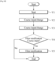
- the controller may determine whether the filter is attached or detached by detecting an increase in the amount of the light emitted from the light emitting part by the sensor part, and may determine whether the clothes have fallen by detecting a decrease in the amount of the light emitted from the light emitting part by the sensor part.
- the controller may be provided to shut down the operation of the least one of the heater or the compressor and put the least one of the heater or the compressor on standby, if the light emitted from the light emitting part is blocked and does not reach the sensor part prior to the operation of the at least one of the heater or the compressor.
- the present disclosure has the effect of being capable of accurately detecting whether clothes have fallen using an illuminance sensor.
- the present disclosure has the effect of being capable of accurately detecting whether a filter is attached or detached using an illuminance sensor.
- the present disclosure has the effect of being capable of determining whether clothes have fallen or whether a filter is attached or detached using an illuminance sensor that is less affected by shock and vibration and has no limit to the lifespan of a light source as long as power is supplied.
- the present disclosure has the effect of being capable of indirectly and quickly determining whether clothes have fallen or whether a filter is attached or detached by detecting a change in the illuminance of light without direct contact of a sensor with the filter.
- the present disclosure has the effect of being capable of determining whether clothes have fallen or whether a filter is attached or detached by detecting a change in the illuminance of light by a sensor part as long as light emitted from a light emitting part reaches the sensor part regardless of where the light emitting part and the sensor part are provided.
- the present disclosure has the effect of being capable of stopping a cycle and controlling whether to proceed with the cycle thereafter, upon detecting that clothes have fallen during clothing treatment or that a filter is not installed.
- FIG. 2 illustrates the appearance of a clothing treatment apparatus 1 of the present disclosure.
- the clothing treatment apparatus of the present disclosure may include a cabinet 100 forming the appearance of the clothing treatment apparatus, and a door 40 rotatably coupled to the cabinet 100.
- the door 40 may include a main body 410 forming the front surface of the cabinet 100, and an installation body 420 extending from one side of the main body 410 so that a display part configured to display information of the clothing treatment apparatus may be installed thereon.
- the installation body 420 may be provided to form a step 43 toward the rear of the cabinet 100 from the main body 410.
- the installation body 20 may be disposed to overlap the main body 410 in the forward and rearward directions at the rear of the main body 410.
- the step 43 may function as a handle.
- the installation body 420 may be formed of a different material or in a different color from the main body 410.
- the installation body 420 may be formed of a translucent material that transmits light emitted from the display.
- an inner case 200 having an accommodation space 220 to accommodate clothes may be provided within the cabinet 100.
- the inner case 200 may be provided with an opening 210 formed at the front portion thereof so that the clothes enter and exit the inner case 200 therethrough, and the opening 210 may be shielded by the door 40.
- the inner case 200 may be formed of a plastic resin-based material, and may be formed of a reinforced plastic resin-based material that is not deformed even by air of a higher temperature than room temperature, heated air (hereinafter, hot air), steam, or moisture.
- hot air heated air
- the inner case 200 may be provided such that the length thereof is longer than the width thereof. Accordingly, the clothes may be accommodated in the accommodation space 220 without being folded and wrinkled.
- the clothing treatment apparatus 1 of the present disclosure may include a holding part 500 that may hold the clothes in the accommodation space 220 of the inner case 200.
- the holding part 500 may include a hanger part 510 provided on the upper surface of the inner case 200 to hold the clothes.
- the clothes When the clothes are held on the hanger part 510, the clothes may be disposed in a state of floating in the air within the accommodation space 220.
- the holding part 500 may further include a pressing part 520 coupled to the inner surface of the door 40 to fix the clothes.
- the hanger part 510 may be provided in a bar shape arranged in the width direction of the inner case 200 to support hangers on which clothes are held. Further, as illustrated, the hanger part 510 may be provided in a hanger shape to allow clothes to be directly held thereon.
- the clothing treatment apparatus of the present disclosure may further include a vibration part that vibrates the hanger part 510 to remove foreign substances, such as fine dust, attached to the clothes.
- the holding part 500 may include the pressing part 520 provided on the door 40 to press and fix the clothes.
- the pressing part 520 may include a support 522 fixed to the inner surface of the door 40 to one surface of the clothes, and a presser 521 configured to press the clothes supported by the support 522.
- the presser 521 may be provided to move toward the support 522 or away from the support 522.
- the presser 521 may be rotatably provided on the inner surface of the support 522 or the door 40.
- the presser 521 and the support 522 may press both sides of the clothes to remove wrinkles from the clothes and create intended creases.
- the clothing treatment apparatus of the present disclosure may have a machine compartment 300 equipped with various devices that may supply at least one of hot air or steam to the accommodation space 220 or purify or dehumidify external air of the cabinet 100.
- the machine compartment 300 may be disposed to be separated or partitioned from the inner case 200, but may be provided to communicate with the inner case 200.
- the machine compartment 300 may be disposed below the inner case 200. Accordingly, when hot air and steam with low specific gravity are supplied to the inner case 200, the hot air and steam may be naturally supplied to the clothes.
- the machine compartment 300 may include a heat supply 340 that may supply hot air to the inside of the inner case 200.
- the heat supply 340 may be provided as a heat pump system, or may be provided as a heater that directly heats air with electric energy.
- the heat supply 340 may be provided to dehumidify and heat air discharged from the inner case 200 again and supply the air to the inner case 200.
- the detailed structure of the heat supply 340 will be described later.
- the machine compartment 300 may include a steam supply 800 that may supply steam to the inside of the inner case 200.
- the steam supply 800 may be provided to directly supply steam to the inside of the inner case 200. The detailed structure of the steam supply 800 will be described later.
- the inner case 200 may have a plurality of through holes 230 formed through one surface of the inner case 200 to communicate with the machine compartment 300.
- air inside the accommodation space 220 may be supplied to the machine compartment 300, and at least one of hot air or steam generated in the machine compartment 300 may be supplied to the accommodation space 200.
- the through holes 230 may include an inflow hole 231 formed through the lower surface of the inner case 200 so that the air inside the inner case 200 is suctioned or discharged to the machine compartment 300 therethrough, and a discharge hole 232 formed through the lower surface of the inner case 200 so that the hot air generated in the machine compartment 300 is discharged therethrough.
- the discharge hole 232 may be disposed in a portion of the lower surface of the inner case 200 close to the rear surface thereof.
- the discharge hole 232 may be disposed to be inclined from the ground between the lower surface and the rear inner surface of the inner case 200 to face the hanger part 510.
- the inflow hole 231 may be disposed in a portion of the lower surface of the inner case 200 close to the front thereof. Accordingly, the inflow hole 231 may be disposed to be spaced apart from the discharge hole 232.
- the through holes 230 may include a steam hole 233 through which steam generated in the steam supply 800 is supplied.
- the steam hole 233 may be disposed on one side of the discharge hole 232.
- a water supply tank 3 capable of supplying water to the steam supply 800 and a drain tank 4 that collects condensed water from the heat supply 340 may be provided in a front portion of the machine compartment 300.
- the water supply tank 3 and the drain tank 4 may be detachably provided in the front portion of the machine compartment 300. Accordingly, the clothing treatment apparatus 1 of the present disclosure may be freely installed without being restricted by a water supply source or a drain source.
- a drawer 5 that is withdrawn from and inserted into the front portion of the machine chamber 300 and has a separate storage space may be further provided in the front portion of the machine chamber 300.
- a steam generator or an iron may be stored in the drawer 5.
- FIG. 3 illustrates the structure of the upper portion of the inner case.
- the hanger part 510 of the clothing treatment apparatus of the present disclosure may include power transmission parts 513 disposed in the upper portion of the inner case 200 and provided to shake the hangers 511.
- a hook 512 on which the hanger 511 is placed or held may be provided at the lower portion of the power transmission part 513.
- the power transmission parts 513 may be provided in plural, and the hooks 512 coupled to the power transmission parts 513 may be provided in plural. Accordingly, a large number of pieces of clothes corresponding to the number of the power transmission parts 513 may be held in the inner case 200 to be refreshed.
- FIG. 3 illustrates that the hanger part 510 and the power transmission parts 513 are arranged in the width direction of the inner case 200.
- the hanger part 510 and the power transmission parts 513 may be arranged in a direction in which the clothes are arranged in the accommodation space. Accordingly, if the clothes are arranged in the forward and rearward directions in the inner case 200, the hanger part 510 and the power transmission parts 513 may be arranged in the forward and rearward directions of the inner case 200.
- the hanger part 510, the plurality of power transmission parts 513, and the plurality of hooks 512 will be described as being arranged in the width direction of the inner case 200, but this is only an example, and the hanger part 510, the plurality of power transmission parts 513, and the plurality of hooks 512 may be arranged in a direction designed so that a plurality of pieces of clothes are held or arranged in the accommodation space.
- the hanger part 510 may further include a driver 514 that provides power to move the power transmission parts 513.
- the driver 514 may be provided to be exposed to the inside of the inner case 200 as long as the driver 514 is capable of transmitting power to the power transmission parts 513. However, because the driver 514 is provided to be operated by receiving electric energy, exposure of the driver 514 to steam or hot air is preferably prevented.
- the driver 514 may be disposed between the upper surface of the inner case 200 and the cabinet 100 so that exposure of the driver 514 to the accommodation space 210 may be prevented.
- the power transmission parts 513 may penetrate the upper surface of the inner case 200 to receive power from the driver 514.
- the power transmission parts 513 penetrate the upper surface of the inner case 200 and extend downward so that the lower ends of the power transmission parts 513 may be exposed to the accommodation space 210.
- the power transmission parts 513 may be provided in a rod shape, a tube shape, a plate shape, or the like in which the length thereof is longer than the thickness thereof.
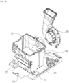
- FIG. 4 illustrates the structure of the machine compartment of the clothing treatment apparatus of the present disclosure.
- FIG. 4(a) is a front view of the machine compartment 300
- FIG. 4(b) is a rear view of the machine compartment 300.
- Components configured to supply hot air to a clothing treatment space, circulate air inside the clothing treatment space, supply steam to the clothing treatment space, or purify air outside the cabinet may be disposed within the machine compartment 300.
- the machine compartment 300 may include a base part 310 configured such that various devices are supported thereby or installed thereon.
- the base part 310 may provide an area where the various devices are installed.
- a circulation duct 320 through which air introduced from the inner case 200 or the outside of the cabinet 100 moves may be installed on the base part 310.
- the circulation duct 320 may be provided in a case shape with an open upper surface, and some of the components of the heat supply 340 may be installed in the circulation duct 320.
- the heat supply 340 may include heat exchangers 341 and 343, which will be described later, and a compressor 342 that supplies a high-temperature and high-pressure refrigerant to the heat exchangers in the circulation duct 320.
- the heat exchangers 341 and 343 may be accommodated in the circulation duct 320 to cool and dehumidify the air flowing through the circulation duct 320 or heat the air to generate hot air.
- an external air duct 370 configured to draw in external air may be installed in front of the circulation duct 320.
- the circulation duct 320 may be provided to communicate with the external air duct 370 to selectively draw in external air.
- the water supply tank and the drain tank may be detachably connected to the front of the circulation duct 320.
- the water supply tank 3 and the drain tank 4 may be disposed to be placed above the external air duct 370.
- the circulation duct 320 may be provided to be coupled to the base part 310, or may be provided integrally with the base part 310.
- the base part 310 and the circulation duct 320 may be manufactured by injection molding.
- the machine compartment 300 may include a base cover 360 provided to allow the circulation duct 320 to communicate with the inflow hole 231.
- the base cover 360 may be provided to be coupled to the upper portion of the circulation duct 320 so as to guide air suctioned through the inflow hole 231 into the inside of the circulation duct 320.
- the base cover 360 may shield the upper surface of the circulation duct 320 to prevent discharge of air inside the circulation duct 320 to the outside.
- the lower portion of the base cover 360 and the upper surface of the circulation duct 20 may form one surface of the flow path of the circulation duct 320.
- the base cover 360 may include an inflow part 362 that connects the inflow hole 231 and the circulation duct 320.
- the inflow part 362 may be provided in a duct shape and serve as an intake duct that delivers air inside the inner case 200 to the circulation duct 320.
- the steam supply 800 connected to the water supply tank 3 to receive water, generate steam, and supply the generated steam to the inner case 200 may be installed in the machine compartment 300.
- the steam supply 800 may be disposed to be placed on the base cover 360.
- the steam supply 800 may be disposed at the rear of the inflow part 362.
- the machine compartment 300 may include a fan installation part 350 provided to allow the circulation duct 320 to communicate with the inner case 200.
- the fan installation part 350 may include a blower fan 353 that provides power to move air inside the circulation duct 320 in one direction, and a fan housing 351 that accommodates the blower fan 353 and is coupled to or extends toward the circulation duct 320.
- the fan installation part 350 may further include an exhaust duct 352 provided to allow the circulation duct 320 to communicate with the discharge hole 232.
- the exhaust duct 352 may be provided to extend from lower portion of the fan housing 351 toward the discharge hole 232 to have a cross-sectional shape and a cross-sectional area corresponding to the discharge hole 232.
- the air inside the inner case 200 may be introduced through the base cover 360, pass through the circulation duct 320, and then be supplied back to the inside of the inner case 200 through the fan installation part 350.
- FIG. 5 illustrates the structure of the base of the machine compartment of the clothing treatment apparatus of the present disclosure.
- the base part 310 may be provided with a compressor installation part 312 in which the compressor 342 configured to supply the refrigerant to the heat exchangers 341 and 342 is installed.
- the compressor installation part 313 may be disposed outside the circulation duct 320.
- a controller or a control panel C that controls the clothing treatment apparatus of the present disclosure may be installed on the base part 310.
- the base part 310 may be provided with a controller installation part 313 that forms a space into which the controller C is inserted below the circulation duct 320.
- the controller C may be provided to control all electronically controlled components, such as the compressor 342, the steam supply 800, and the blower fan 353.
- controller C is inserted into the base part 310 to be supported thereby, and vibration or shock applied to the controller C may be buffered.
- controller C is disposed close to all electronic components, occurrence of control errors, such as noise, may be minimized.
- the steam supply is disposed above the circulation duct 320, and the controller C is disposed below the circulation duct 320. Therefore, the circulation duct 320 may be provided in a straight duct shape between the steam supply 800 and the controller C. Accordingly, the flow resistance of air passing through the circulation duct 320 may be minimized.
- the circulation duct 320, the external air duct 370, the steal supply 800, the controller C, and the steam supply 340 may be provided in a module format on the base part 310.
- the base part 310 may be easily installed and maintained while being withdrawn from or inserted into the machine compartment 300 forwards or rearwards.
- FIG. 5(a) is a perspective view of the base part 310 viewed from the front
- FIGs. 5(b) and 5(c) are perspective views of the base part 310 viewed from the rear.
- the base part 310 may be installed on a base plate forming the lower surface of the clothing treatment apparatus.
- the base part 310 may itself form the lower surface of the clothing treatment apparatus.
- the base part 310 may include a base bottom 311 forming a support surface.
- the base bottom 311 may form the lower surface of the clothing treatment apparatus. Further, the base bottom 311 may be installed on the upper surface of the bottom surface of the cabinet 100 forming the lower surface of the clothing treatment apparatus.
- the base part 310 may be provided integrally with the circulation duct 320 forming at least a portion of a flow path in which air flows.
- the circulation duct 320 may be formed to extend upward from the base bottom 311.
- the circulation duct 320 may include a duct body 321 that extends from the base bottom 311 to form the flow path, a heat exchanger installation part 3212 that provides a space in which an evaporator 341 or a condenser 343 is installed in the duct body 321, and an air discharge part 323 that is provided at the rear of the duct body 321 and through which air inside the duct body 321 is discharged.
- the air discharge part 323 may be provided in a pipe shape that extends rearward from the duct body 321.
- the diameter of the air discharge part 323 may be smaller than the width of the duct body 321.
- the air discharge part 323 may be connected to the fan housing 350. The air discharged from the air discharge part 323 may be guided into the inner case 200 through the fan housing 350.
- the circulation duct 320 may include an external air intake part 322 formed to penetrate the front surface of the duct body 321.
- the external air intake part 322 may be provided to communicate with the external air duct 370.
- the external air duct 370 may be placed in front of the external air intake part 322 to be supported.
- the circulation duct 320 may be provided with a damper that opens and closes the external air intake part 322. Inflow of external air into the circulation duct 320 may be allowed or blocked by opening and closing the damper.
- the base part 310 may include a compressor installation part 312 that provides a space in which the compressor 342 is installed.
- the compressor installation part 312 may be formed on one side of the base bottom 311, and may be formed integrally with the base bottom 311.
- the compressor installation part 312 may have a protrusion that supports the compressor 342.
- the compressor installation part 312 may be disposed on the rear portion of the base part 310.
- the compressor installation part 312 may be disposed such that at least a portion thereof overlaps the air discharge part 323 in the width direction.
- a buffer member that reduces vibration transmitted from the compressor 342 may be installed in the compressor installation part 312.
- the buffer member may be fixed to the protrusion.
- the base part 310 may include the controller installation part 313 in which the controller C is installed.
- the controller installation part 313 may be formed between the base bottom 311 and the circulation duct 320.
- the controller installation part 313 may be formed between the base bottom 311 and the bottom surface of the circulation duct 320.
- the controller installation part 313 may be provided in a duct shape configured such that one of the front portion and the rear portion thereof is open below the circulation duct 320.
- controller installation part 313 The structure of the controller installation part 313 will be described later.
- FIG. 6 illustrates the structure of the circulation duct of the clothing treatment apparatus.
- the circulation duct 320 may extend upward from the base bottom to form the flow path in which air flows.
- the circulation duct 320 may include the heat exchanger installation part 3212 that provides the space in which the evaporator 341 and the condenser 3432 are installed.
- the heat exchanger installation part 3212 may be provided within the duct body 321.
- the duct body 321 may be provided with an open upper surface.
- the condenser 343 and the evaporator 341 may be inserted through the opening of the duct body 321 to be installed.
- the opening of the duct body 321 may be shielded by the base cover 360, and the base cover 360 and the duct body 321 may form the flow path of the circulation duct 320.
- the front surface of the duct body 321 may disposed to be spaced apart rearward from the front end of the base bottom 311.
- the base bottom 311 may secure a support surface 3111 on which one or more of the above-described water supply tank 3 or drain tank 4 and the external air duct 370 are installed and supported.
- the heat supply 340 may include the evaporator 341 provided as a heat exchanger installed in the circulation duct 320 to cool and dehumidify the air introduced into the circulation duct 320, the condenser 343 provided as a heat exchanger configured to heat the air having passed through the evaporator 341 to generate hot air, the compressor 342 configured to supply the refrigerant that exchanges heat with the air to the condenser 343 and disposed outside the circulation duct 320, and an expansion valve 344 configured to expand and cool the refrigerant having passed through the condenser 343.
- the evaporator 341 provided as a heat exchanger installed in the circulation duct 320 to cool and dehumidify the air introduced into the circulation duct 320
- the condenser 343 provided as a heat exchanger configured to heat the air having passed through the evaporator 341 to generate hot air
- the compressor 342 configured to supply the refrigerant that exchanges heat with the air to the condenser 343 and
- the heat exchanger installation part 3212 may secure a great height, and the heights of the condenser 343 and the evaporator 341 may be increased.
- the widths of the condenser 343 and the evaporator 341 in the forward and rearward directions may be reduced, and thus the number of refrigerant pipes passing through the condenser and the evaporator may be reduced. Accordingly, an effect of reducing the flow loss of air passing through the condenser and evaporator may be exhibited.
- the sum of the length of the evaporator 341 and the length of the condenser 343 may be smaller than the length of the heat exchanger installation part 3212. Accordingly, the length of the heat exchanger installation part 3212 in the forward and rearward directions may be equal to or smaller than half the length of the duct body 321.
- the heat exchanger installation part 3212 may be sufficiently separated from the external air intake part 322, a sufficient space into which external air and the air inside the inner case 200 are introduced may be secured in the circulation duct 320.
- the inside of the duct body 321 may include an installation partition 3211 that separates the heat exchanger installation part 3212 from the outside of the heat exchanger installation part 3212.
- the installation partition 3211 may be provided to protrude from the side surface of the duct body 321 to support the front portion of the evaporator 341.
- the duct body 321 may be expanded in width based on the installation partition 3211, and extend rearward.
- the width of the heat exchanger installation part 3212 may be greater than half the width of the base part 310.
- the width of the circulation duct 320 may be greater than half the width of the base part 310.
- the width of the condenser 343 and the width of the evaporator 341 may also be greater than half the entire width of the base part 310.
- the fan housing 350 may be disposed to overlap the condenser 343 or the evaporator 341 in the forward and rearward directions. Accordingly, air having passed through the condenser 343 and the evaporator 341 may be introduced into the fan housing 350 without bending the flow path. That is, the air introduced into the circulation duct 320 has an effect of minimizing flow loss because the flow path is not bent during the process of moving the air to the fan housing.
- FIG. 7 illustrates the shape of the circulation duct of the clothing treatment apparatus of the present disclosure.
- the base bottom 310 and the circulation duct 320 of the base part 310 may be formed as a single body by injection molding.
- a mold configured to form the inner surface of the duct body 321 may be withdrawn upward from the inside of the duct body 21 to be removed.
- the wall surface of the duct body 321 may be inclined at a predetermined angle with respect to the removal direction of the mold.
- the width of a lower surface 321a of the duct body 321 may be longer than the width of an upper surface 321b of the duct body 321.
- a distance between the wall surfaces of the duct body 321 facing each other may increase as the duct body gets farther from the base bottom 311.
- a distance between the left and right surfaces of the circulation duct facing each other may increase in the withdrawal direction of the mold. Accordingly, the mold may be easily removed.
- the discharge part 323 may include an air extension pipe 3231 that extend from the rear portion of the duct body 321 to have a reduced diameter or width, and an air discharge pipe 3232 that extends from the air extension pipe 3231 in a pipe shape having a uniform diameter to form a hollow 3233 formed therein.
- the air extension pipe 3231 may function as a nozzle and thus increase the rate of discharged air.
- a mold for forming the air discharge part 323 may be removed a shown in the figure above.
- the mold may be withdrawn forward from the inside of the air discharge part 323 toward the inside of the circulation duct 320, and then be removed toward the open upper surface of the circulation duct 320.
- the air discharge part 323 may be formed in a structure that facilitates withdrawal of the mold.
- FIG. 8 is a cross-sectional view of the circulation duct.
- the installation partition 3211 may protrude inward from the inner wall of the duct body 321, or be formed by indenting the outer wall of the circulation duct inward.
- the heat exchanger installation part 3212 may be formed between the heat exchanger installation partition 3211 and the air discharge part 323.
- the mold for forming the air discharge part 323 may be withdrawn forward from the air discharge part 323 and then withdrawn upward to be removed. It is necessary to prevent the mold for forming the air discharge part 323 from interfering with the heat exchanger installation partition when the mold is withdrawn forward from the inside of the air discharge part 323. For this purpose, the design values of the air discharge part 323 may be adjusted.
- a mold for forming the front portion of the air discharge part 323 and a mold for forming the rear portion of the air discharge part 323 based on a parting line 3233 of the air discharge part 323 of this figure may be separately provided. Accordingly, the removal directions of the molds may be different from each other.
- the mold for forming the front portion of the air discharge part 323 based on the parting line of the air discharge part 323 may be withdrawn forward, and the mold for forming the rear portion of the air discharge part 323 based on the parting line of the air discharge part 323 may be withdrawn rearward.
- a distance 1 321a may be smaller than a distance 2 321c in the figure.
- the distance 1 321a may mean a distance between the parting line of the air discharge part 323 and the front end of the air discharge part 323.
- the distance 1 321a may mean a distance between the parting line of the air discharge part 323 and the rear opening of the circulation duct.
- the distance 2 321c may mean a distance between the front end of the air discharge part 323 and the heat exchanger installation partition.
- the distance 2 323c may mean a distance between the rear opening of the circulation duct and the heat exchanger installation partition 3211.
- FIG. 9 illustrates the structure of the controller installation part provided on the base part of the clothing treatment apparatus of the present disclosure.
- FIG. 9(a) illustrates an embodiment in which the controller C is installed in the controller installation part 313.
- the controller C may be provided so that the clothing treatment apparatus of the present disclosure is capable of controlling all devices necessary to perform an arbitrary course for performing the refreshing cycle on clothes.
- the controller C may be provided as a PCB substrate, but is not limited thereto, and may be provided as various devices for control.
- the controller C may be inserted into the controller installation part 313 to be placed therein.
- the controller installation part 313 may be disposed below the circulation duct 320.
- the bottom surface of the circulation duct 320 may form the upper surface of the controller installation part 313.
- the controller installation part 313 may be disposed below the air discharge part 323.
- the controller installation part 313 may be formed integrally with the base bottom 311.
- the controller installation part 313 may be formed as a sunken space under the circulation duct during a process of molding the circulation duct 320 in the base part 310.
- the controller C may be introduced into the controller installation part 313 forward from the rear in a sliding manner.
- Brackets 3131 provided to surround the controller may be provided on the surface of the controller C.
- the brackets 3131 may be disposed on the upper and lower portions of the controller to prevent foreign substances from entering the controller.
- brackets 3131 may prevent damage to a circuit board in the controller C due to heat or vibration transmitted to the controller C.
- the brackets 3131 may be formed of a metal material.
- FIG. 9(b) illustrates a state in which the controller is installed in the controller installation part.
- the controller C may be installed at a predetermined angle with the base bottom 311.
- the controller C may be disposed to be inclined toward a water reservoir 326. Accordingly, if water leaks to the upper portion of the controller C, the water may quickly escape the controller C, and the bottom surface of the circulation duct 320 may be molded to be inclined toward the water reservoir 326.
- the controller C may include supporters 3132 that are formed to protrude from the side surface of the controller C.
- the controller installation part 313 may include ribs 3134 that protrude from both side surfaces of the installation part.
- the supporters 3132 of the controller may be held on the upper portions of the ribs 3134.
- the supporters 3132 of the controller may support the entire load of the controller C.
- the controller C may be spaced apart from the base bottom 311 by a predetermined distance.
- the ribs 3134 may be formed integrally with the base part 310.
- the ribs 3134 may be formed together with the base part 310 when the base part 310 is injection-molded, and may be provided integrally with the base bottom 311, the circulation duct 320, etc.
- a protrusion 3133 formed to protrude may be provided on the front surface of the controller C.
- a guide that protrudes rearward may be provided on the inner surface of the controller installation part 313.
- the protrusion may be coupled to the guide.
- the protrusion may be inserted into the guide. When the controller is inserted into the controller installation part, the controller may be aligned in the correct position by coupling the protrusion to the guide.
- the positions of both side surfaces of the controller may be determined in the above-described manner in which the supporters are placed on the ribs.
- the controller may be coupled to the correct position of the controller installation part without a separate fastening member using the above coupling process.
- FIG. 10 illustrates the structure of the air discharge part 323 of the clothing treatment apparatus of the present disclosure.
- the base part 310 may include the air discharge part 323 that discharges treated air toward the fan housing.
- the air discharge part 323 may be provided to allow the fan housing 350 to communicate with the inside of the circulation duct 320 or the duct body 321.
- the air discharge part 323 may be provided in a bell mouth shape.
- the air discharge part 323 provided in the bell mouth shape may reduce air flow loss and improve air circulation efficiency.
- the air discharge pipe 3232 of the air discharge part 323 may be provided in a pipe shape, and during the mold removal process based on the parting line 3233, the mold disposed in front of the parting line 3233 may be withdrawn forward and the mold disposed at the rear of the parting line 3233 may be withdrawn rearward.
- the fan installation part 350 may be coupled to the air discharge pipe 3232 to be supported thereby.
- the fan housing 351 may have a coupling hole coupled to the outer circumferential surface of the air discharge pipe 3232, and the blower fan 353 may be disposed in the coupling hole.
- the fan housing 351 may include the exhaust duct 352 that extends from the outer circumferential surface of the blower fan 353 or the outside to the discharge hole 232.
- the fan housing 351 and the exhaust duct 352 may form a flow path in which the blower fan 353 is accommodated and air moves.
- a motor that rotates the blower fan 353 may be coupled to the outside of the fan housing 351 to be supported thereby.
- FIG. 11 illustrates the structure of the base cover of the clothing treatment apparatus of the present disclosure.
- the base cover 360 may be provided to be coupled to the upper surface of the circulation duct 320 so as to prevent the inside of the circulation duct 320 from being exposed.
- the base cover 360 may include an inflow body 361 coupled to the upper surface of the circulation duct 320 to allow the inner case 200 to communicate with the circulation duct 320, and a shielding body 363 extending from the inflow body 361 to shield the circulation duct 320.
- the inflow body 361 may be provided in a duct shape to allow the inflow hole 231 of the inner case to communicate with the inside of the circulation duct 320.
- the inflow body 361 may be provided to protrude farther upward than the shielding body 363.
- the inflow body 361 may be disposed in front of the evaporator 341 so as not to face the evaporator 341 and the condenser 343, and may be disposed in front of the partition 3211.
- the inflow body 361 may serve as an inflow duct that moves air of the inner case 200 to the circulation duct 320.
- the inflow body 361 may be provided with the inflow part 362 through which the air of the inner case 200 may pass.
- the base cover 360 may include a first rib 362a extending in the width direction of the inflow body 361, and a second rib 362b spaced apart rearward from the first rib 362a and extending in the width direction of the inflow body 361.
- the first rib 362a and the second rib 362b may be provided in parallel.
- the first rib 362a and the second rib 362b may be provided in a plate shape extending in the vertical direction, and the height thereof may correspond to the height of the inflow body 361.
- the front surface of the inflow body 361 and the first rib 362a may form a first inlet 3621
- the first rib 362a and the second rib 362b may form a second inlet 3623
- the second rib 362b and the rear surface of the inflow body 361 may form a third inlet 3622.
- the first inlet 3621 and the third inlet 3622 may be provided with the same area, and the second inlet 36222 may be provided with a smaller area than the first inlet 3621 and the third inlet 3622.
- the base cover 360 may include a damper part 364 provided to open and close the inflow part 362, and a driver 365 coupled to the damper part 364 to control opening and closing of the damper part 364.
- the damper part 364 may include a first damper 3641 provided to open and close the first inlet 3621, and a second damper 3642 provided to open and close the third inlet 3622.
- the first damper 3641 may be provided in a plate shape with an area corresponding to the first inlet 3621, and may be rotatably coupled to both side surfaces of the inflow body 361 within the first inlet 3621.
- the second damper 3642 may be provided in a plate shape with an area corresponding to the third inlet 3622, and may be rotatably coupled to both side surfaces of the inflow body 361 within the third inlet 3622.
- the second inlet 3623 may be provided with a cut-off filter 366 that allows air to pass therethrough but may filter out foreign substances, such as fine dust and lint.
- the cut-off filter 366 may be provided to be inserted into the second inlet 3623 to divide the first inlet 3621 and the third inlet 3622.
- the cut-off filter 366 may be disposed to extend from the second inlet 3623 to come into contact with the bottom surface of the circulation duct 320.
- the cut-off filter 366 may be provided as a filter capable of filtering moisture.
- the cut-off filter 366 may be provided as a HEPA filter, or the like.
- a shielding member that shields the second inlet 3623 when the cut-off filter 366 is inserted thereinto may be further coupled to the second inlet 3623.
- the driver 365 may include a motor that provides power to selectively rotate the first damper 364 and the second damper 365, and a plurality of gear members that is engaged with the motor and rotates to selectively rotate the first damper 364 and the second damper 365.
- the first inlet 3611 and the third inlet 3622 may be selectively opened due to the driver 365.
- air accommodated in the inner case 200 may be introduced into the circulation duct 320 along the first inlet 3621, or may be introduced into the circulation duct 320 along the third inlet 3622.
- the driver 365 may control the first damper 3641 and the second damper 3642 to open both the first inlet 3611 and the third inlet 3622, and may control the first damper 3641 and the second damper 3642 to shield both the first inlet 3611 and the third inlet 3622.
- the driver 365 may be provided in any structure as long as it may be provided to rotate the first damper 3641 and the second damper 3642.
- the driver 365 may be provided as a combination of a motor, a driving gear rotated by the motor, and driven gears coupled to the first damper and the second damper and rotated due to rotation of the driving gear.
- the base cover 360 may include the shielding body 363 that extends from the inflow body 361 and is capable of shield the evaporator 341 and the condenser 343.
- the shielding body 363 may be provided in a plate shape.
- the base cover 360 may be detachably coupled to the upper surface of the circulation duct 320 through an inflow hook 3612 extending from the lower surface of the inflow body 361.
- the circulation duct 320 may be provided with a coupling part detachably coupled to the inflow hook 3612.
- FIG. 12 illustrates the structure of the external air duct.
- the external air duct 370 may be coupled to the base part 310.
- the external air duct 370 may be provided to communicate with the external air intake part 322.
- the external air duct 370 may include an external air damper 373 that opens and closes the external air intake part 322, and an external air driver 374 that rotates the external air damper 373 to selectively open the external air intake part 322.
- the external air damper 373 may be provided in a plate shape that may seal the external air intake part 322, and may be rotatably coupled to both side surfaces of the external air intake part 322.
- the external air driver 374 may be provided as an actuator coupled to the external air duct 370 or the circulation duct 320 to rotate the external air damper 373.
- the outdoor air duct 370 may include an extension duct 372 that extends forward from the external air intake part 322 in front of the external air intake part 322, and an intake duct 371 that extends forward from the extension duct 372 and allows external air to be introduced.
- the intake duct 371 may be provided to extend from the lower portion of the extension duct 372, and the water supply tank 3 and the drain tank 4 may be disposed on the upper portion of the intake duct 371.
- the water supply tank 3 and the drain tank 4 may be coupled to or placed on the intake duct 371.
- the intake duct 371 may include an external air hole 3711 formed at one end or a free end thereof so that external air is suctioned through the external air hole 3711, and a partition rib 3712 provided to partition the external air hole 3711.
- the external air hole 3711 may be provided to be disposed below the door 40 so as not to be shielded by the door 40.
- the partition rib 3712 may be provided to partition the inside of the external air hole 3711 so as to prevent foreign substances or a user's body from being inserted into the external air hole 3711.
- the intake duct 371 and the circulation duct 320 may communicate with each other.
- the door 40 may further include a discharge hole through which air inside the inner case 200 is discharged to the outside, and a discharge damper that selectively opens and closes the discharge hole.
- the discharge hole may be provided to face the accommodation space of the inner case 200.
- the dehumidified air may be discharged through the discharge hole.
- the external air may be filtered while passing through the cut-off filter 366, and be discharged again to the outside of the cabinet 100.
- FIG. 13 illustrates the flow of air flowing through the circulation duct.
- the external air damper 373 may be controlled to shield the external air intake part 322, the first damper 3641 may be controlled to open the first inlet 3621, and the second damper 3642 may be controlled to shield the third inlet 3622.
- the air inside the inner case 200 may be introduced into the first inlet 3621 to be filtered while passing through the cut-off filter 366.
- the air having passed through the cut-off filter 366 may be dehumidified and heated while passing through the evaporator 341 and the condenser 343.
- the air having passed through the heat exchangers may pass through the fan installation part 350 and be supplied to the inside of the inner case 200.
- This state may be a state in which steam is not supplied to the inner case 200. This is because, if steam is supplied to the inner case 200, the moisture wets the cut-off filter 366, and the performance of the cut-off filter 366 may not be guaranteed.
- the air inside the inner case 200 may pass through the first inlet 3641 and the cut-off filter 366 to filter out foreign substances, such as lint.
- the external air damper 373 may be controlled to shield the external air intake part 322, the first damper 3641 may be controlled to shield the first inlet 3621, and the second damper 3642 may be controlled to open the third inlet 3622.
- the air inside the inner case 200 may be introduced into the third inlet 3622. Because the third inlet 3622 is provided downstream from the cut-off filter 366, the air introduced into the third inlet 3622 may not pass through the cut-off filter 366.
- the air having passed through the cut-off filter 366 may be dehumidified and heated while passing through the evaporator 341 and the condenser 343.
- the air having passed through the heat exchangers may pass through the fan installation part 350 and be supplied to the inside of the inner case 200.
- the air inside the inner case 200 may be introduced into the third inlet 3622, and be prevented from being introduced into the first inlet 3621, thereby preventing the cut-off filter 366 from being exposed to moisture.
- the external air damper 373 may be controlled to open the external air intake part 322, the first damper 3641 may be controlled to shield the first inlet 3621, and the second damper 3642 may be controlled to shield the third inlet 3622.
- the air inside the inner case 200 may be prevented from being introduced into the inflow part 362, and only the air outside the cabinet 100 may be introduced into the circulation duct 320 and pass through the cut-off filter 366. Thereby, foreign substances, such as fine dust, contained in the external air may be filtered out by the cut-off filter 366.
- the air having passed through the cut-off filter 366 may be dehumidified and heated while passing through the evaporator 341 and the condenser 343.
- the air having passed through the heat exchangers may pass through the fan installation part 350 and be supplied to the inside of the inner case 200, thereby supplying fresh hot air to clothes.
- the air outside the cabinet may be discharged in a purified and dehumidified state while passing through the cut-off filter 366 and the heat supply 340.
- the clothing treatment apparatus of the present disclosure may determine the flow directions of the air inside the inner case 200 and the air outside the cabinet by controlling the external air driver 374 and the inflow drier 365 through the controller C.
- FIG. 14 illustrates the installation structure of the steam supply.
- the steam supply 800 may be placed on the base cover 360 to be supported thereby.
- the steam supply 800 may include a steam case 810 that is placed on the base cover 360 and stores water to generate steam.
- the steam supply 800 may further include an installation bracket 870 that may fix the steam case 810 to the base cover 360.
- the installation bracket 870 may be coupled to the base cover 360 to fix the steam case 810.
- the installation bracket 870 may include a lower panel 871 that supports the lower surface of the steam case 810, and side panels 872 that support both side surfaces of the steam case 810 on the lower panel 871.
- the installation bracket 870 may further include one or more fixing clips 873 that extend from the side panels 872 to prevent the steam case 810 from being detached.
- the fixing clips 873 may be detachably provided on the upper portion or the side surfaces of the steam case 810.
- the compressor 342 may be disposed below the steam supply 800.
- the installation bracket 870 may be provided to block transfer of heat generated from the compressor or heat generated from the refrigerant compressed by the compressor to the steam supply 800.
- the installation bracket 870 may also block transfer of fire to the steam supply 800 in the event of a fire occurring in the compressor 342.
- the base cover 360 may include a fastener 3631 that is provided on the shielding body 360 and detachably coupled to the steam supply 800.
- the fastener 3631 may be provided in a structure that is detachably coupled to a protrusion protruding from the lower portion of the steam case 810.
- the steam case 810 may be stably placed on the base cover 360.
- the steam case 810 is disposed above the circulation duct 320 and a distance from the inner case 200 is shorter, condensation of steam generated in the steam case 810 before reaching the inner case 200 may be minimized.
- FIG. 15 illustrates the detailed structure of the steam supply.
- the steam supply 800 may include the steam case 810 that may receive and store water to generate steam, and a heater part 840 accommodated in the steam case 810 to heat water to generate steam.
- the steam case 810 may be provided in the form of a case with an open upper portion to accommodate the heater part 840.
- the steam supply 800 may further include a case cover 820 coupled to the steam case 810 to prevent the heater part 840 from being exposed to the outside and prevent the water from leaking.
- a water level sensor 850 that detects the water level of the steam case 810 and a steam sensor 60 that detects the temperature inside the steam case 810 or detects whether steam is generated in the steam case 810 may be installed on the case cover 820.
- the steam case 810 may include a case body 811 that provides a space configured to store the water and accommodate the heater part 840.
- the case body 811 is provided with an open upper portion so that various parts may be easily installed in the case body 811.
- the case body 811 may include a heater insertion hole 8111 formed through one side thereof so that the heater part 840 may be inserted into or withdrawn from the heat insertion hole 8111.
- the case body 811 may include a recovery pipe 814 configured to discharge water accommodated in the case body 811 to the outside.
- the recovery pipe 814 may be kept closed by a shielding plug 8141 so as to be opened only when removing residual water in the steam case 810, and may include a shielding clip 8142 that maintains the coupled state of the shielding plug 8141 to the recovery pipe 814 to prevent the shielding plug 8141 from being separated arbitrarily.
- water inside the steam case 800 may be discharged through the recovery pipe 814.
- a heater fixing part 830 that may support or fix the heater part 840 may be installed in the case body 811.
- the heater fixing part 830 may include a fixing clip 831 that fixes the heater part 840, and a clip fastening member 833 that fixes the fixing clip 831 to the case body 811.
- the fixing clip 831 may be provided to accommodate or surround at least a portion of the heater part 840.
- the steam supply 800 may be provided with a water supply pipe 815 that supplies water.
- the water supply pipe 815 may be provided to communicate with the water supply tank 30 to receive water therefrom.
- the water supply pipe 815 may be provided on the case cover 820, or may be disposed on the upper portion of the steam case 810. Accordingly, counterflow of water through the water supply pipe 815 may be prevented.
- the steam supply 800 may be provided with a steam pipe 813 that discharges steam generated by operation of the heater part 840 to the outside.
- the steam pipe 813 may be provided on the upper portion of the case cover 820 to prevent water from being discharge into the steam pipe 813.
- the steam pipe 813 may communicate with the steam hole 233 of the inner case 200.
- the case cover 820 may be provided with a water level sensor hole 854 in which the water level sensor may be installed.
- the water level sensor 850 may include one or more contact protrusions 852 that are inserted into the water level sensor hole 854 and immersed in water to detect the water level, and a sensor body 851 that is coupled to the water level sensor hole 854 or supported by the case cover 820 to maintain the contact protrusions 852 in a floating state within the steam case 810.
- the sensor body 851 may be coupled to the case cover 820 through a sensor fastening member 853.
- the case cover 820 may be provided with an insertion hole 64 in which the steam sensor 860 may be installed.
- the steam sensor 860 may include a detection device 861 inserted into the insertion hole 864 to detect whether steam is generated in the steam case 810, a support 863 that fixes the detection device 861 to the case cover 20, and a coupling member 862 that couples the support 863 to the case cover 820.
- the detection device 861 may be provided as a humidity sensor or a temperature sensor to detect whether steam is generated in the steam case 810.
- case cover 820 may be provided with cover hooks 821 that may extend forward and be coupled to the base cover 860.
- fixing protrusions 822 that may fix the lower portion of the inner case 200 or a separate discharge part 900 may be provided at the rear portion of the case cover 820.
- the heater part 840 may be inserted into the heater insertion hole 8111 to be accommodated in the steam case 810, and be provided to receive power to heat water.
- the heater part 840 may be provided as a sheath heater, etc., and may be controlled by a controller C to be repeatedly operated and stopped.
- the heater part 840 may include a first heater 841 that receives first power to heat water, and a second heater 842 that receives power greater than the first power to heat water.
- the second heater 842 may be provided to heat a larger amount of water than the first heater 841 to generate a larger amount of steam.
- the first heater 841 and the second heater 842 may be provided to consume respective power amounts divided from the maximum heater power amount allowed for the heater part 840. That is, if the first heater 841 is provided to consume a portion of the maximum heater power amount, the second heater 842 may be provided to consume the remainder of the maximum heater power amount.
- the first heater 841 may be provided to consume 600 W
- the second heater 842 may be provided to consume 880 W. 20 W may be left considering errors, etc.
- the heater part 840 may include three or more heaters.
- the heater part 840 may include the first heater 841, the second heater 842, and a third heater 843, and the first heater 841, the second heater 842, and the third heater 843 may be provided to consume respective power amounts divided from the maximum heater power amount.
- the heater part 340 will be described as including the first heater 841 and the second heater 842.
- the first heater 841 and the second heater 842 may be formed as a U-shaped metal pipe.
- the heater part 840 may include a heater sealer 843 that may fix the first heater 841 and the second heater 842 and seal the heater insertion hole 8111, and may include a terminal part 844 that supplies current to the first heater 841 and the second heater 842.
- the terminal part 844 may include a first terminal 844a that supplies current to the first heater 841, and a second terminal 844b that supplies current to the second heater 842.
- the first heater 841 and the second heater 842 may be disposed at the same height. Therefore, the first heater 841 and the second heater 842 may be provided to heat water of the same water level to generate steam.
- the controller C may control a steam amount generated using both or selectively the first heater 841 and the second heater 842, and a power amount consumed.
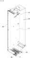
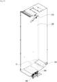
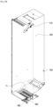
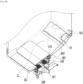
- FIG. 16 illustrates the clothing treatment apparatus of the present disclosure in which a light emitting part and a sensor part are installed.
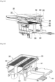
- the present disclosure may provide the clothing treatment apparatus including the cabinet 100 having the opening in the front portion thereof, the inner case 200 provided in the cabinet 100 to provide the space configured to accommodate clothes, the door 40 coupled to the cabinet to open and close the opening, the hanger part 510 provided in the upper portion of the inner case to hold the clothes, the machine compartment 300 provided below the bottom surface of the inner case 200 to supply at least one of hot air or steam to the inside of the inner case 200, a light emitting part 600 provided in one of the inner case 200, the door 40, and the machine compartment 300 to emit light to the inside of the inner case 200, and a sensor part 700 provided in one of the inner case 200, the door, and the machine compartment to detect whether the clothes having fallen off of the hanger part 510 block at least a portion of the light emitted from the light emitting part 600.
- the clothing treatment apparatus of the present disclosure may determine whether the clothes have fallen by utilizing the sensor part 700 detecting a change in illuminance as long as the light emitted from the light emitting part 600 reaches the sensor part 700 regardless of where the light emitting part 600 and the sensor part 700 are provided.
- the clothing treatment apparatus may include the light emitting part 600 provided to emit light toward the inside of the inner case 200.
- the light emitting part 600 may emit any wavelength of light as long as the sensor part 700 can detect the same.
- the wavelength of the light emitted from the light emitting part 600 may be in the ultraviolet spectrum, the visible spectrum, or the like.
- the wavelength of the light emitted from the light emitting part 600 is most preferably in the visible spectrum rather than the infrared spectrum, the ultraviolet spectrum, etc. Infrared light may penetrate objects, and thus pass through clothes even if the clothes have fallen, whereas visible light is electromagnetic waves that are visible to the human eye, and is not capable of penetrating objects. In addition, use of visible light is more appropriate for detecting clothes having fallen using blocking of light, and may protect user eyesight.
- the light source of the light emitting part 600 may be provided as any device that emits light, such as an LED or a light bulb.
- the clothing treatment apparatus may include the sensor part 700 that receives the light emitted from the light emitting part 600.
- the sensor part 700 may be provided as an illuminance sensor that detects a change in the illuminance of the light emitted from the light emitting part 600.
- Illuminance is a measure of brightness, and when a large amount of light is incident, the illuminance increases, and conversely, when a small amount of light is incident, the illuminance decreases.
- the sensor part 700 may detect at least one of whether the light emitted from the light emitting part 600 is received or the intensity of the light.
- the sensor part 700 may be provided at a position where it is capable of completely receiving the light emitted from the light emitting part 600.
- the detailed installation positions of the light emitting part 600 and the sensor part 700 will be described later.
- At least one light emitting part 600 and at least one sensor part 700 may be provided.
- the amount of light received by the sensor part 700 increases, and thus, it is possible to more accurately determine whether clothes have fallen.
- the clothing treatment apparatus of the present disclosure may determine whether clothes have fallen from a change in the illuminance of light detected by the sensor part 700 when the clothes have fallen during the clothing treatment process.
- the sensor part 700 is disposed closer to the bottom surface of the inner case 200 than the hanger part, the sensor part 700 detects a first value when the clothes do not fall, and the controller C may determine that the clothes have fallen when the sensor part 700 detects a value smaller than the first value.
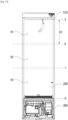
- FIG. 17 illustrates division of spatial areas of the inner case of the clothing treatment apparatus of the present disclosure.
- the inner case 200 may include a first spatial area V1, a second spatial area V2, and a third spatial area V3 that are divided depending on height.
- the first spatial area V1 may be defined as a space between a first position a and a second position b.
- the second position b may be spaced apart downward from the first position a by a first height h1.
- the second position b may be spaced apart downward from the first position a by 1/3 of a length from the first position a to a fourth position d.
- the height of the first spatial area V1 may be a first height h1.
- the first height h1 may be greater than or equal to the length of the hanger in the height direction.
- the first height h1 may be 1/3 of the length from the first position a to the fourth position d.
- the hanger part 510 may be installed in the first spatial area V1.
- Clothes that have a shorter length than the first height and are small, such as a top, baby's clothes, or a skirt, may be provided in the first spatial area V1.
- the second spatial area V2 may be disposed below the first spatial area V1 and may be defined as a space between the second position b and a third position c provided below the second position b.
- the second spatial area V2 may include the central portion of the inner case 200 in the height direction.
- Clothes having a relatively normal length such as a shirt or a jacket, may be provided in the second spatial area V2.
- the third spatial area V3 may be disposed below the second spatial area V2 and may be defined as a space between the third position c and the fourth position d.
- Clothes having a long length such as a coat or pants, may be provided in the third spatial area V3.
- Fallen clothes may be provided in the lower portion of the third spatial area V3.
- the light emitting part 600 and the sensor part 700 may be provided in at least one of the first spatial area V1, the second spatial area V2, or the third spatial area V3.
- the sensor part 700 may be provided below the first position a.
- the sensor part 700 may be provided above the fourth position d.
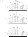
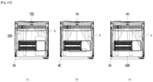
- FIG. 18 illustrates one embodiment of the positions of the light emitting part and the sensor part of the clothing treatment apparatus of the present disclosure.
- the clothing treatment apparatus or the controller C of the present disclosure may determine whether clothes have fallen by detecting an increase in illuminance by the sensor part 700.
- the clothing treatment apparatus or the controller C may determine whether the clothes have fallen by detecting an increase in illuminance.
- One light emitting part 600 and one sensor part 700 may be provided.
- the light emitting part 600 and the sensor part 700 may be provided in the same spatial area.
- the light emitting part 600 and the sensor part 700 are provided below a fifth position e, the light emitted from the light emitting part 600 is not blocked from the beginning and reaches the sensor part 700, and therefore the sensor part 700 may not detect a change in illuminance.
- the sensor part 700 may not detect an increase in illuminance if the light emitting part 600 and the sensor part 700 are disposed in the second spatial area V2 or the third spatial area V3, short and small clothes are provided only in the first spatial area V1, and even if the clothes have fallen, the sensor part 700 may not detect an increase in illuminance.
- the light emitting part 600 and the sensor part 700 are preferably provided at least above the fifth position e.
- the fifth position e is provided in at least one of the first spatial area V1, the second spatial area V2, or the third spatial area V3. Even if the fifth position e is in the first spatial area V1, the light emitting part 600 and the sensor part 700 are preferably provided in the upper portion of the first spatial area V1 in order to detect falling of clothes.
- the light emitting part 600 and the sensor part 700 are preferably provided below the hanger part 510. Accordingly, the sensor part 700 may detect a change in the illuminance of light using the fact that when clothes block the light emitted from the light emitting part 600 while minimizing influence of the hanger part 510.
- FIG. 19 illustrates another embodiment of the positions of the light emitting part and the sensor part of the clothing treatment apparatus of the present disclosure.
- the sensor part 700 and the light emitting part 600 may be provided in different spatial areas.
- the light emitting part 600 may be provided in the second spatial area V2
- the sensor part 700 may be provided in the first spatial area V1.
- the light emitting part 600 may be provided to face the sensor part 700 so that the sensor part 700 may detect the light.
- the light emitting part 600 may be provided to emit light into an area where the sensor part 700 may detect the light.
- the light emitting part 600 and the sensor part 700 may be provided on the surfaces of the inner case 200 that face each other.
- the light emitting part 600 may be provided so that the light emitted from the light emitting part 600 may pass through the first spatial area V1. Accordingly, even if short clothes are hung, the sensor part 700 may detect an increase in the illuminance of light using the fact that clothes block the light emitted from the light emitting part 600.
- a reflection part 400, etc. may be additionally installed to guide the light emitted from the light emitting part 600 to the sensor part 700 provided in a different spatial area.
- FIG. 20 illustrates another embodiment of the positions of the light emitting part and the sensor part of the clothing treatment apparatus of the present disclosure.
- At least one light emitting part 600 and at least one sensor part 700 may be provided.
- the number of the light emitting parts 600 and the number of the sensor parts 700 may not be the same, and if two or more light emitting parts 600 are provided, two or more sensor parts 700 may be also provided.
- the two or more light emitting parts 60 may be provided in different spatial areas.
- the light emitting parts 600 may include a first light emitting part 610 provided in the first spatial area V1 and a second light emitting part 620 provided in the second spatial area V2.
- the first light emitting part 610 and the second light emitting part 620 may be provided on one surface of the inner case 200.
- the first light emitting part 610 and the second light emitting part 620 may be provided in parallel in the height direction of one surface of the inner case 200.
- the sensor part 700 may be provided on a surface facing the surface on which the light emitting parts 600 are provided so as to face at least one of the first light emitting part 610 or the second light emitting part 620.
- the first light emitting part 610 may be provided so that light emitted from the first light emitting part 610 passes through the first spatial area V1 and the second spatial area V2 and reaches the sensor part 700.
- the second light emitting part 620 may be provided so that light emitted from the second light emitting part 620 passes through the second spatial area V2 and reaches the sensor part 700.
- the clothing treatment apparatus or the controller C may detect falling of clothes provided in the first spatial area V1 using blocking of light emitted from the first light emitting part 610, and may detect falling of clothes provided in the second spatial area V2 using blocking of light emitted from the second light emitting part 620.
- the sensor part 700 may determine whether clothes have fallen by detecting a change in the illuminance of light.
- the clothing treatment apparatus or the controller C may easily control the sensor part 700 at once.
- FIG. 21 illustrates another embodiment of the positions of the light emitting part and the sensor part of the clothing treatment apparatus of the present disclosure.
- clothes may be hung on the hanger parts 510 provided in the first spatial area V1 in a direction from one side surface of the inner case 200 toward the other side surface facing the side surface.
- the light emitting parts 600 and the sensor parts 700 may be provided on both side surfaces of the inner case 200, respectively. However, in the case in which a plurality of pieces of clothes is provided, even if clothes fall, the light emitted from the light emitting parts 600 may be blocked by other clothes provided in front of the fallen clothes, and the sensor parts 700 may not detect a change in illuminance.
- the light emitting parts 600 and the sensor parts 700 may be provided on at least one of the rear inner surface of the inner case 200 or the door.
- the light emitting parts 600 may be provided on the door so that light emitted from the light emitting parts 600 is directed toward the inside of the inner case 200.
- the sensor parts 700 may be provided on the rear inner surface of the inner case 200 so as to face the light emitting parts 600.
- the light emitting parts 600 may be provided on the rear inner surface of the inner case 200, and the sensor parts 700 may be provided on the door.
- the light emitting parts 600 and the sensor parts 700 may be provided on the same line as the width direction of the clothes hanging on hanger parts 510.
- the light emitting parts 600 may be provided to emit light toward the sides of the clothes hanging on the hanger parts 510. Therefore, if the clothes do not fall, the clothes hanging on the hanger parts 510 may block the light emitted from the light emitting parts 600.
- the light emitting parts 600 and the sensor parts 700 may be provided as many as the hanger parts 510. For example, if the number of the hanger parts 510 is five, five light emitting parts 600 and five sensor parts 700 may be provided.
- the light emitting parts 600 may include a first light emitting part 610, a second light emitting part 620, a third light emitting part 630, a fourth light emitting part 640, and a fifth light emitting part 650.
- the first light emitting part 610, the second light emitting part 620, the third light emitting part 630, the fourth light emitting part 640, and the fifth light emitting part 650 may be provided in a line such that the interval therebetween is the same as the interval between the hanger parts 510.
- the sensor parts 700 may further include a first sensor part 710, a second sensor part 720, a third sensor part 730, a fourth sensor part 740, and a fifth sensor part 750.
- the first sensor part 710, the second sensor part 720, the third sensor part 730, the fourth sensor part 740, and the fifth sensor part 750 may be provided such that the interval therebetween is the same as the interval between the hanger parts 510.
- the first sensor part 710, the second sensor part 720, the third sensor part 730, the fourth sensor part 740, and the fifth sensor part 750 may be provided in a line such that the interval therebetween is the same as the interval between the first light emitting part 610, the second light emitting part 620, the third light emitting part 630, the fourth light emitting part 640, and the fifth light emitting part 650.
- the first sensor part 710, the second sensor part 720, the third sensor part 730, the fourth sensor part 740, and the fifth sensor part 750 may be provided to face the first light emitting part 610, the second light emitting part 620, the third light emitting part 630, the fourth light emitting part 640, and the fifth light emitting part 650, respectively.
- first light emitting part 610 If clothes between the first light emitting part 610 and the first sensor part 710 have fallen, light emitted from the first light emitting part 610 may reach the first sensor part 710 due to the falling of the clothes, and the first sensor part 710 may detect an increase in illuminance of light.
- the light emitting parts 600 and the sensor parts 700 may be provided in one of the first spatial area V1, the second spatial area V2, and the third spatial area V3.
- the light emitting parts 600 and the sensor parts 700 are most preferably provided in the first spatial area V1.
- the sensor parts 700 detect light emitted from the light emitting part 600 provided on the same line as the fallen clothes.
- the clothing treatment apparatus or the controller C may detect an increase in the illuminance of the light emitted from the light emitting part 600.
- the clothing treatment apparatus may determine not only whether clothes have fallen but also which clothes have fallen by detecting an increase in the illuminance of light by the sensor parts 700.
- FIG. 22 illustrates another embodiment of the positions of the light emitting part and the sensor part of the clothing treatment apparatus of the present disclosure.
- the clothing treatment apparatus or the controller C may determine whether clothes have fallen by detecting a decrease in illuminance by the sensor part 700. If clothes have fallen, the fallen clothes block light emitted from the light emitting part 600. Therefore, the light emitted from the light emitting part 600 does not reach the sensor part 700, and thus the sensor part 700 may detect an abnormal decrease in illuminance.
- the sensor part 700 may be disposed closer to the bottom surface of the inner case 200 than the hanger part, and the sensor part 700 may detect the first value when the clothes do not fall, and if the sensor part 700 detects a value smaller than the first value, the controller C may determine that the clothes have fallen.
- the light emitting part 600 and the sensor part 700 may be arranged in the width direction or the forward and rearward directions based on the bottom surface of the inner case 200. Accordingly, a portion of the light emitted from the light emitting part 600 may be blocked by the clothes fallen on the bottom surface of the inner case 200.
- the sensor part 700 may be disposed on the rear inner surface of the inner case 200 and the light emitting part 600 may be disposed in front of the sensor part 700, or the sensor part 700 may be disposed on one side surface of the inner case 200 and the light emitting part 600 may be disposed on one side surface of the sensor part 700.
- the sensor part 700 and the light emitting part 600 may be provided on different surfaces of the inner case 200.
- the sensor part 700 may be provided on a surface facing the surface on which the light emitting part 600 is provided.
- the light emitting part 600 and the sensor part 700 are preferably provided to face each other.
- the light emitting part 600 and the sensor part 700 may be provided on both side surfaces of the inner case 200 to face each other.
- each of the light emitting part 600 and the sensor part 700 may be provided on at least one of the rear inner surface of the inner case 200 or the door so as to face each other.
- the light emitting part 600 may be disposed in the middle of the door in the width direction. Accordingly, a non-detectable area may be reduced as much as possible regardless of the position of the sensor part 700, and thus the sensor part may detect the fallen clothes regardless of the position of the fallen clothes, and may receive more light emitted from the light emitting part 600.
- the light emitting part 600 and the sensor part 700 may be provided in the same spatial area.
- the light emitting part 600 and the sensor part 700 may be provided in the third spatial area V3. Because clothes are located in the third spatial area V3 when the clothes have fallen, the light emitting part 600 and the sensor part 700 are preferably provided in the third spatial area V3.
- the light emitting part 600 and the sensor part 700 may be disposed below the hanger part 510. Further, the light emitting part 600 and the sensor part 700 may be provided below the height e of the lowest end of the clothes. That is, the light emitting part 600 and the sensor part 700 may be disposed closer to the bottom surface of the inner case 200 than the hanger part 510. Accordingly, the clothing treatment apparatus or the controller C may determine whether clothes have fallen while minimizing influence of clothes hanging above.
- the sensor part 700 may determine whether clothes have fallen by detecting a decrease in the illuminance of light due to the fallen clothes, it is possible to determine whether the clothes have fallen using only the decrease of the illuminance of the light blocked by the fallen clothes without being affected by the length of the clothes, etc.
- the sensor part 700 determines whether clothes have fallen by detecting a decrease in the illuminance of light due to the fallen clothes, it is possible to determine whether the clothes have fallen more easily and accurately even when a plurality of pieces of clothes is provided.
- usage of the light emitting part 600 and the sensor part 700 may be minimized, thereby being capable of reducing material costs, etc.
- FIG. 23 illustrates another embodiment of the positions of the light emitting part and the sensor part of the clothing treatment apparatus of the present disclosure.
- Each of the light emitting part 600 and the sensor part 700 may be provided on at least one of the upper portion or the lower portion of the inner case 200 so as to face each other.
- the light emitting part 600 may be provided on the upper surface of the inner case 200.
- the light emitting part 600 may be provided below the hanger part 510.
- the sensor part 700 may be provided on the bottom surface of the inner case 200 so as to be shielded by clothes when the clothes have fallen.
- the sensor part 700 may be provided in the machine compartment or on the inflow body. This may be advantageous in repair and power supply.
- the light emitting part 600 may be provided below the inner case 200, and the sensor part 700 may be provided in the upper portion of the inner case 200.
- the light emitting part 600 may be provided in the machine compartment, or may be provided in the inflow body.
- the light emitting part 600 and the sensor part 700 may be provided in a straight line to face each other.
- the clothing treatment apparatus or the controller C may determine whether clothes have fallen by detecting a decrease in the illuminance of light by the sensor part 700.
- At least one light emitting part 600 and at least one sensor part 700 may be provided. Particularly, the more sensor parts 700 there are, the more preferable it is. In most cases, because, when clothes have fallen, they have fallen around an area where they were hung due to gravity, a plurality of sensor parts 700 may be provided to more accurately determine whether the clothes have fallen.
- the sensor parts 700 may include a first sensor part 710, a second sensor part 720, and a third sensor part 730.
- the first sensor part 710, the second sensor part 720, and the third sensor part 730 may be provided in a line.
- At least one of the first sensor part 710, the second sensor part 720, or the third sensor part 730 may be provided to face the light emitting part 600.
- the clothes When clothes have fallen, the clothes may have fallen on at least one of the first sensor part 710, the second sensor part 720, or the third sensor part 730 and thus shield the at least one of the first sensor part 710, the second sensor part 720, or the third sensor part 730.
- the clothing treatment apparatus or the controller C may determine whether clothes have fallen by detecting a decrease in the illuminance of light by at least one of the first sensor part 710, the second sensor part 720, or the third sensor part 730.
- FIG. 24 illustrates one embodiment of the reflection part of the clothing treatment apparatus of the present disclosure.
- the sensor part 700 may not detect a change in illuminance because the light is not blocked by the clothes.
- the clothing treatment apparatus may include a first fall area S1 provided between the light emitting part 600 and the sensor part 700, and a non-detectable area X defined as an area other than the first fall area S1.
- the fallen clothes block the light emitted from the light emitting part 600 and the sensor part 700 may detect a decrease in illuminance, but if the clothes have fallen into the non-detectable area, the fallen clothes do not block the light emitted from the light emitting part 600 and the sensor part 700 may not detect a decrease in illuminance.
- the light emitted from the light emitting part 600 is blocked by the portion of the clothes and the sensor 700 may detect a decrease in illuminance.
- the clothing treatment apparatus may further include the reflection part 400.
- the reflection part 400 may be provided as at least one reflector.
- the reflector may be provided on a surface other than the surfaces on which the light emitting part 600 and the sensor part 700 are provided among the inner surfaces of the inner case 200.
- the reflection part 400 may include a first reflector 410 provided on one side surface of the inner case 200, and a second reflector 420 provided on a surface facing the surface on which the first reflector 410 is provided.
- Each of the first reflector 410 and the second reflector 420 may be provided on the center of one surface of the inner case 200 in the width direction. Accordingly, a second fall area S2 and a third fall area S3 may be expanded to reduce the non-detectable area.
- the first reflector 410 and the second reflector 420 may be provided to face each other.
- Each of the first reflector 410 and the second reflector 420 may be provided on the center of one surface of the inner case 200 in the width direction.
- the clothing treatment apparatus may further include the second fall area S2 formed by light reflected by the first reflector 410, and the third fall area S3 formed by light reflected by the second reflector 420.
- the non-detectable area is reduced compared to if the reflection part 400 is not provided. If clothes have fallen and a portion of the clothes is located in one of the first fall area S1, the second fall area S2, and the third fall area S3, the light emitted from the light emitting part 600 may be blocked by the fallen clothes and the sensor part 700 may detect a decrease in illuminance.
- the clothing treatment apparatus may determine whether clothes have fallen even if the clothes have fallen into any area of the bottom surface of the inner case 200 by minimizing the non-detectable area X.
- FIG. 25 illustrates a filter part of the clothing treatment apparatus of the present disclosure.
- the clothing treatment apparatus 1 may further include a filter part 380 in the upper portion of the machine compartment 300 to prevent dust from entering the inside of the circulation duct 320.
- the filter part 380 may be mounted on the inflow body 361 to filter out dust introduced into the inflow body 361.
- the filter part 380 may include a body filter 386 mounted on the upper portion of the inflow body 361 of the base cover 360 to shield a portion of the upper surface of the inflow body 361.
- the body filter 386 may be formed of a mesh material that may block large dust particles and allow light to pass therethrough.
- the filter part 380 may further include a body cover 385 on which the body filter 386 is placed.
- the body cover 385 may be mounted on the upper portion of the inflow body.
- the body cover 385 may shield one surface of each of the upper portions of the first inlet 3621 and the third inlet 3622. Portions of the body cover 385 that shield the upper surfaces of the first inlet 3621 and the third inlet 3622 may be provided through perforation.
- the body cover 385 may block large dust particles when the body filter 386 is not installed, thereby being capable of preventing dust from entering the inside of the circulation duct 320.
- the filter part 380 may further include a filter fixing part 384 to fix the body cover 385 and the body filter 386.
- the filter fixing part 384 may be provided on the upper portion of the base cover 360.
- the circumferential surface of the body cover 385 may be coupled to the filter fixing part 384, and may be attached to or detached from the filter fixing part 384.
- the clothing treatment apparatus may further include a filter cover 382 on the upper portion of the body cover 385.
- the filter cover 382 may be provided to have a larger width than the width of the body cover 385.
- the filter cover 382 may shield one surface of the body filter 386.
- the lower surface of the filter cover 382 may be formed as a lattice-shaped injection molded product.
- the filter cover 382 may be provided to be spaced apart from the bottom surface of the inner case 200 so that air inside the inner case 200 may be introduced into the circulation duct 320.
- a blocking cover 381 may be provided on the upper portion of the filter cover 382.
- the blocking cover 381 may completely shield the open upper surface of the machine compartment 300.
- FIG. 26 illustrates position and area division of the clothing treatment apparatus of the present disclosure.
- the clothing treatment apparatus 1 may include a first area V1 provided on one side of the filter part 380 and a second area V2 provided on the other side of the filter part 380.
- the first area V1 and the second area V2 may be divided by the body filter 386 interposed therebetween.
- the light emitting part 600 and the sensor part 700 may be provided in at least one of the first area V1 or the second area V2.
- the first area V1 may be defined as an area including the inner case 200, the upper portion of the machine compartment 300, the upper portion of the body cover 385, etc.
- the second area V2 may be defined as an area including the lower portion of the inner case 200, the lower portion of the machine compartment 300, the lower portion of the body cover 385, the inflow body 361, the circulation duct 320, etc.
- the first area V1 and the second area V2 may not be divided into upper and lower parts, left and right parts, or the like based on the body filter 386, and it is sufficient to provide the body filter 386 between the first area V1 and the second area V2.
- the light emitting part 600 and the sensor part 700 may be provided at at least one of positions A, B, C, D, and E.
- the parts shown in this figure are an example of each position, and the light emitting part 600 and the sensor part 700 may be provided at positions not shown in this figure.
- the positions A, B, C, and D may be provided in the first area.
- the position A may include an area corresponding to the upper portion of the inner case 200.
- the position A may be the upper surface of the inner case 200, the lower portion of the hanger part 510, the hanger part 510, or the like.
- the position B may include several side surfaces excluding the upper surface and the lower surface of the inner case 200 or the inner surface area of the door 40.
- the position B may be provided at the center of one surface of the inner case 200 in the width direction.
- the position C may include the lower surface of the inner case 200 and an area adjacent to the lower portion of the inner case 200.
- the position C may correspond to an area including one of areas adjacent the lower ends of the side surfaces of the inner case 200 close to the lower surface of the inner case 200.
- the position C may be provided at the lower portion of the door 40 close to the lower surface of the inner case 200.
- the position C may be the lower surface of the inner case 200.
- the position D may include an area that is located below the lower surface of the inner case 200 or the upper surface of the filter part 380 and above the body filter 386.
- the position D may include the lower surface of the filter cover 382.
- the position D may correspond to the center of the lower surface of the filter cover 382 in the width direction.
- the position D may be provided at the exact center of the filter cover 382.
- the position D may be provided on one surface of the upper portion of the body cover 385.
- the position D may be provided on the front surface or the rear surface of the body cover 385.
- the position E may include an area below the body filter 386.
- the position E may be disposed on the inflow duct of the circulation duct 320.
- the position E may be provided on one surface of the inflow body 361.
- the position E may be provided in at least one of the first inlet 3621, the second inlet 3622, or the third inlet 3623.
- the position E may be provided on the front surface or the rear surface of the inflow body 361.
- the position E may be provided on one surface of the inflow body 361 extending from at least one of the first rib 362a or the second rib 362b of the inflow body 361.
- the position E may be provided on the lower surface of the perforated plate of the body cover 385 and one surface of the inflow body 361 extending from at least one of the first rib 362a or the second rib 362b.
- the light emitting part 600 is provided at the position E, deterioration of the performance of the light emitting part 600 due to dust, etc. filtered out by the body filter 386 may be prevented, and exposure of the user's eyes to light may be prevented. Further, power supply and repair may be facilitated, and influence of clothes hanging in the inner case 200 may be minimized.
- FIG. 27 illustrates another embodiment of the positions of the light emitting part and the sensor part of the clothing treatment apparatus of the present disclosure.
- the light emitting part 600 and the sensor part 700 may be provided in different areas with respect to the bottom surface of the inner case 200.
- the light emitting part 600 and the sensor part 700 may be provided in different areas among the first area V1 and the second area V2.
- the filter part 380 may be disposed between the light emitting part 600 and the sensor part 700.
- the light emitted from the light emitting part 600 may penetrate the filter part 380 and be detected by the sensor part 700.
- One of the light emitting part 600 and the sensor part 700 may be disposed above the filter part 380, and the other may be disposed below the filter part 380.
- the light emitting part 600 may be provided in the first area V1, and the sensor part 700 may be provided in the second area V2. Alternatively, the light emitting part 600 may be provided in the second area V2, and the sensor part 700 may be provided in the first area V1.
- one of the light emitting part 600 and the sensor part 700 may be disposed above the body filter 386, and the other may be disposed below the body filter 386.
- each of the light emitting part 600 and the sensor part 700 may be provided at the position A, B, C, or D or provided at the position E.
- the sensor part 700 may be provided at at least one of the position A, B, C, or D.
- the light emitting part 600 may be provided at at least one of the position A, B, C, or D.
- the reflection part 400 configured to guide the light emitted from the light emitting part 600 to the sensor part 700 may be further provided.
- the detailed structure and position of the reflection part 400 will be described later.
- the sensor part 700 may be provided at the position A, and the light emitting part 600 may be provided at the position E.
- the sensor part 700 may be provided in the upper portion of the inner case 200.
- one of the light emitting part 600 and the sensor part 700 may be disposed below the filter part 380, and the other one of the light emitting part 600 and the sensor part 700 may be disposed on the upper surface of the inner case 200.
- one of the light emitting part 600 and the sensor part 700 may be disposed below the filter part 380 and the hanger part.
- the sensor part 700 may be provided at the center of the inner case 200 in the width direction.
- the light emitting part 600 may be provided below the body filter 386 or on the rear surface of the inflow body 361.
- the light emitting part 600 may be provided at the center of the machine compartment in the width direction.
- the light emitting part 600 and the sensor part 700 may be provided on the same line in the height direction of the clothing treatment apparatus.
- the filter cover 382 and the blocking cover 381 may not be provided.
- One light emitting part 600 and one sensor part 700 may be provided.
- the positions of the light emitting part 600 and the sensor part 700 may be interchanged.
- FIG. 28 illustrates another embodiment of the positions of the light emitting part and the sensor part of the clothing treatment apparatus of the present disclosure.
- the sensor part 700 is provided in the upper portion of the inner case 200, the light emitted from the light emitting part 600 may not reach the sensor part 700 due to clothes hanging in the inner case 200. As a result, the clothing treatment apparatus or the controller C may not be able to determine whether the filter is attached or detached./
- the sensor part 700 may be provided closer to the lower surface than the upper surface of the inner case 200.
- the sensor part 700 may be disposed on the inner circumferential surface of the inflow hole 231, or the like, and may be disposed below the lower surface of the inner case 200.
- the light emitting part 600 and the sensor part 700 may be disposed below the filter cover 382.
- the light emitting part 600 and the sensor part 700 may be disposed in the inflow body 361 to prevent exposure of the light emitting part 600 and the sensor part 700 to the inner case 200.
- the sensor part 700 may be provided at the position D, and the light emitting part 600 may be provided at the position E.
- the sensor part 700 may be provided on the lower surface of the filter cover 382.
- One light emitting part 600 and one sensor part 700 may be provided. Accordingly, material costs and manufacturing costs of the clothing treatment apparatus may be reduced, and the clothing treatment apparatus may efficiently detect whether clothes have fallen using one sensor part 700.
- the sensor part 700 may be disposed at a position which may identify the light emitting part 600.
- the sensor part 700 may be disposed to face the light emitting part in the height direction of the clothing treatment apparatus or in the flow path direction of the inflow duct.
- the sensor part 700 may be provided on the same line as the center of the inner case in the width direction, not the center of the circulation duct in the width direction.
- the sensor part 700 may be provided at the center of the lower surface of the filter cover 382 in the width direction. Accordingly, the light emitting part 600 and the sensor part 700 may be provided in a straight line at the center of the inner case 200 in the width direction.
- the sensor part 700 may be provided at the exact center of the filter cover 382.
- the sensor part 700 is not provided on the same line as the light emitting part 600.
- the light emitting part 600 and the sensor part 700 may be provided on the same line in the height direction of the clothing treatment apparatus.
- the positions of the light emitting part 600 and the sensor part 700 may be interchanged.
- FIG. 29 illustrates another embodiment of the positions of the light emitting part and the sensor part of the clothing treatment apparatus of the present disclosure.
- the sensor part 700 may be provided at the position D, and the light emitting part 600 may be provided at the position E.
- the sensor part 700 may be provided above the body filter 386 or on the rear surface of the body cover 385.
- the light emitting part 600 may be provided below the body filter 386 or on the rear surface of the inflow body 361.
- the light emitting part 600 and the sensor part 700 may be provided at the center of the machine compartment in the width direction.
- the light emitting part 600 and the sensor part 700 may be provided on the same line in the height direction of the clothing treatment apparatus.
- One light emitting part 600 and one sensor part 700 may be provided. Accordingly, material costs and manufacturing costs of the clothing treatment apparatus may be reduced, and the clothing treatment apparatus may efficiently detect whether clothes have fallen using one sensor part 700.
- the filter cover and the blocking cover 381 may be omitted. Accordingly, even if the user does not install the filter cover or the blocking cover 381, it may be possible to determine whether the body filter 386 is attached or detached or the contamination level thereof.
- the clothing treatment apparatus or the controller C may determine whether the body filter 386 is attached or detached or the contamination level thereof while minimizing influence of clothes provided in the inner case 200.
- the positions of the light emitting part 600 and the sensor part 700 may be interchanged.
- FIG. 30 illustrates another embodiment of the positions of the light emitting part and the sensor part of the clothing treatment apparatus of the present disclosure.
- At least one sensor part 700 and at least one light emitting part 600 may be provided.
- the amount of light received by the sensor part 700 increases, and thus, it is possible to more accurately determine whether the filter is attached or detached.
- the number of the light emitting parts 600 and the number of the sensor parts 700 may not be the same, and if two or more light emitting parts 600 are provided, two or more sensor unis 700 may also be provided.
- the light emitting parts 600 may include a first light emitting part 610 and a second light emitting part 620 provided to emit light toward the body filter 386.
- the first light emitting part 610 and the second light emitting part 620 may be provided at the position E.
- the first light emitting part 610 and the second light emitting part 620 may be provided on one surface of the inflow body 361.
- the first light emitting part 610 and the second light emitting part 620 may be disposed on the inner surface of the inflow body 361 to be exposed.
- the first light emitting part 610 may be provided on the front surface of the inflow body 361
- the second light emitting part 620 may be provided on the rear surface of the inflow body 361.
- the first light emitting part 610 and the second light emitting part 620 may be provided to face each other in the forward and rearward directions of the inflow body 361.
- the first light emitting part 610 may be provided so that light emitted from the first light emitting part 610 passes through the body filter 386 and reaches the sensor part 700.
- the second light emitting part 620 may be provided so that light emitted from the second light emitting part 620 passes through the body filter 386 and reaches the sensor part 700.
- the sensor part 700 may be provided at the position D.
- the sensor part 700 may be provided on the lower surface of the filter cover 382.
- the sensor part 700 may be provided at the center of the lower surface of the filter cover 382 in the width direction.
- the sensor part 700 may be provided at the exact center of the filter cover 382. Thereby, it may receive evenly the light emitted from the first light emitting part 610 and the second light emitting part 620.
- the clothing treatment apparatus or the controller C may more accurately measure the contamination level of the body filter 386.
- the clothing treatment apparatus or the controller C may easily control the sensor part 700 at once.
- FIG. 31 illustrates another embodiment of the positions of the light emitting part and the sensor part of the clothing treatment apparatus of the present disclosure.
- a plurality of light emitting parts 600 and a plurality of sensor parts 700 may be provided in the same number. If a plurality of light emitting parts 600 is provided, a plurality of sensor parts 700 may be provided.
- two sensor parts 700 may be provided.
- the light emitting parts 600 may include a first light emitting part 610 and a second light emitting part 620 provided to emit light toward the body filter 386.
- the first light emitting part 610 and the second light emitting part 620 may be provided at the position E.
- the first light emitting part 610 and the second light emitting part 620 may be provided on one surface of the inflow body 361.
- the first light emitting part 610 may be provided on the front surface of the inflow body 361
- the second light emitting part 620 may be provided on the rear surface of the inflow body 361.
- the first light emitting part 610 and the second light emitting part 620 may be provided in parallel in the forward and rearward directions of the inflow body 361.
- the first light emitting part 610 may be provided so that light emitted from the first light emitting part 610 passes through the body filter 386 and reaches one of the sensor parts 700.
- the second light emitting part 620 may be provided so that light emitted from the second light emitting part 620 passes through the body filter 386 and reaches the other one of the sensor parts 700.
- the sensor parts 700 may be provided to face at least one light emitting part 600.
- the sensor parts 700 may include a first sensor part 710 disposed above the first light emitting part 610 to receive the light emitted from the first light emitting part 610, and a second sensor part 720 disposed above the second light emitting part 620 to receive the light emitted from the second light emitting part 620.
- the first sensor part 710 and the second sensor part 720 may be provided at the position D.
- the first sensor part 710 may be disposed to face the first light emitting part 610
- the second sensor part 720 may be disposed to face the second light emitting part 620.
- the first sensor part 710 and the second sensor part 720 may be provided on the lower surface of the filter cover 382.
- the first sensor part 710 and the second sensor part 720 may be provided at the center of the lower surface of the filter cover 382 in the width direction or the center of the inner case 200 in the width direction.
- the first sensor part 710 and the second sensor part 720 may be provided in parallel in the forward and rearward directions of the filter cover 382.
- FIG. 32 illustrates another embodiment of the positions of the light emitting part and the sensor part of the clothing treatment apparatus of the present disclosure.
- the light emitting part 600 and the sensor part 700 may be disposed below the body filter 386. That is, both the light emitting part 600 and the sensor part 700 may be provided at the position E.
- One light emitting part 600 and one sensor part 700 may be provided. Accordingly, material costs and manufacturing costs of the clothing treatment apparatus may be reduced, and the clothing treatment apparatus may efficiently detect whether clothes have fallen using one sensor part 700.
- the sensor part 700 may be provided below the body filter 386.
- the sensor part 700 may be provided below the body cover 385.
- the sensor part 700 may be provided below the perforated plate of the body cover 385.
- the sensor part 700 may be provided on one surface of the inflow body 361 extending from at least one of the first rib or the second rib.
- the sensor part 700 may be provided to be in contact with the lower surface of the perforated plate of the body cover 385 and one surface of the inflow body 361 extending from at least one of the first rib or the second rib.
- the sensor part 700 may be provided on one surface of the inflow body 361, and the light emitting part 600 may be provided on one surface of the body cover 385.
- the clothing treatment apparatus may further include the reflection part 400 provided to guide the light emitted from the light emitting part 600 to the sensor part 700 through the body filter 386.
- the reflection part 400 may be provided below the filter cover 382.
- the refection part 400 may be provided in a straight line with the light emitting part 600.
- the reflection part 400 may be provided so that the light emitted from the light emitting part 600 reaches the sensor part 700.
- the detailed structure and position of the reflection part 400 will be described later.
- the body filter 386 if the body filter 386 is not installed, the light emitted from the light emitting part 600 penetrates the body cover 385 and is reflected by the reflection part 400.
- the light reflected by the reflection part 400 reaches the sensor part 700, and the sensor part 700 may detect an increase in illuminance.
- FIG. 33 illustrates one embodiment of the positions of the light emitting part and the sensor part for sterilizing the filter part of the clothing treatment apparatus of the present disclosure.
- the conventional clothing treatment apparatus had a problem in that dust due to clothing treatment could accumulate on the body filter 386 and cause microorganisms harmful to the human body to occur in the body filter 386. Because the user had to directly remove the body filter 386 having the accumulated dust after a cycle was completed, there was a problem of poor convenience and hygiene.
- the conventional clothing treatment apparatus had a sterilization effect by steam in a steam cycle during the clothing treatment process, but there was a problem in that microorganisms could remain in the body filter 386 even after the cycle was completed.
- the present disclosure provides the clothing treatment apparatus including the light emitting part 600 that performs a function of sterilizing the body filter 386 using light.
- the light emitting part 600 may be provided to sterilize the body filter 386 through the light.
- the body filter 386 is located in the upper portion of the machine compartment and is vulnerable to heat or temperature, there is an advantage in that the inside of the machine compartment is not affected if the body filter 386 is sterilized using light.
- the clothing treatment apparatus may include the light emitting part 600 that emits light of a specific wavelength toward the body filter 386.
- the light emitting part 600 may be provided at any position as long as it is provided to evenly radiate light throughout the entire area of the body filter 386.
- the filter part 380 may further include the reflection part 400 to evenly radiate light throughout the entire area of the boy filter 386.
- the light emitting part 600 may be provided to emit light in the ultraviolet spectrum.
- the light emitting part 600 may be provided to emit visible light having a wavelength of 405 nm. Visible light having the wavelength of 405 nm is harmless to the human body, and microorganisms may be sterilized with the visible light alone.
- a photocatalyst may be added to the body filter 386.
- a chemical substance that emits a sterilizing substance upon coming into contact with visible light may be applied to the filter part 380.
- the light emitting part 600 may capture odor particles when used together with the photocatalyst, thereby being capable of performing a deodorizing function.
- FIG. 34 illustrates a control method of sterilizing the filter part of the clothing treatment apparatus of the present disclosure.
- the control method of the clothing treatment apparatus may include a filter sterilization step A3 of sterilizing the body filter 386 using the light emitting part 600.
- a course input/change step A1 may be performed.
- the clothing treatment apparatus may further include an input part provided on the door 40 or the cabinet 100 to receive a course input or change command.
- the user may select and input a desired course through the input part.
- the compressor 342 the heater part 840, the vibration part 520, etc. start to operate accordingly.
- the heater part 840 starts to operate to generate steam.
- a clothing treatment step A2 may be performed.
- the clothing treatment step A2 may include at least one of a steam injection step of supplying steam to the inside of the inner case 200 by operating the heater part 840 or a drying step of supplying hot air to the inside of the inner case 200 by operating the compressor 342.
- the filter sterilization step A3 may be automatically performed after the clothing treatment step A2 has been completed.
- the filter may be sterilized using light emitted from the light emitting part 600 regardless of the clothing treatment step, such as the steam injection step or the drying step.
- the body filter 386 may be automatically sterilized without the user having to worry about sterilizing the body filter 386, thereby providing convenience.
- the user may also turn on/off the function of automatically performing the filter sterilization step A3.
- FIG. 35 illustrates another control method of sterilizing the filter part of the clothing treatment apparatus of the present disclosure.
- This figure shows that a filter sterilization input step B4 is performed if the function of automatically performing the filter sterilization is turned off.
- the filter sterilization input step B4 may be performed by user's setting in a sterilization course input step B3 after a clothing treatment step B2 has been completed. Accordingly, the body filter 386 may be sterilized only if the user wants. Specifically, a filter sterilization step B5 may be performed only if a filter sterilization course B5 is input in the sterilization course input step B3.
- a step using at least one of the heat pump systems may not be performed.
- the filter sterilization step may be performed at any time when the filter sterilization course is input in the course input step B3 during standby (when storing clothes).
- the clothing treatment apparatus of the present disclosure may eliminate harmful bacteria, viruses, etc. and prevent reproduction thereof by sterilizing the filter using the light emitting part 600.
- FIG. 36 illustrates another embodiment of the positions of the light emitting part and the sensor part of the clothing treatment apparatus of the present disclosure.
- the conventional clothing treatment apparatus there was a problem that it had to have a device configured to detect falling of clothes and a device configured to detect attachment or detachment of the body filter 386. As a result, the conventional clothing treatment apparatus required a plurality of parts and had inconvenience of having to determine and control the parts separately by the controller C.
- Light is advantageous in that a change in illuminance of light may be detected without directly contacting a sensor, and regardless of where the light emitting part 600 and the sensor part 700 are provided, light emitted from the light emitting part 600 only needs to reach the sensor part 700. Therefore, if light is used, it is possible to simultaneously determine whether clothes have fallen and whether the body filter 386 is attached or detached using at least one light emitting part 600 or at least one sensor part 700.
- the present disclosure provides the clothing treatment apparatus including the cabinet 100 having the opening in the front portion thereof, the inner case 200 provided in the cabinet 100 to provide the space configured to accommodate clothes, the door 40 coupled to the cabinet 100 to open and close the opening, the hanger part 510 provided in the upper portion of the inner case to hold the clothes, the machine compartment 300 provided below the inner case 200 and including the inflow body 361 into which air is introduced from the inner case and the exhaust duct that discharges air to the inner case 200, the filter part 380 mounted on the inflow body 361 to filter out dust introduced into the inflow body 361, the light emitting part 600 provided in one of the inner case 200, the door 40, the inflow body 361, and the exhaust duct to emit light toward the filter part 380 and the inside of the inner case 200, and the sensor part 700 provided in the inner case 200 or the door 40 to detect the light emitted from the light emitting part 600 and having passed through the filter part 380, and further including the controller C that determines whether the clothes have fallen and whether the filter part 380 is attached or detached depending
- the clothing treatment apparatus of the present disclosure may determine whether the clothes have fallen or whether the body filter 386 is attached or detached through a change in the illuminance of the light detected by the sensor part 700. Specifically, the clothing treatment apparatus or the controller C may determine whether the clothes have fallen or whether the body filter 386 is attached or detached through the fact that when clothes have fallen, the illuminance of the light decreases due to the fallen clothes, and when the body filter 386 is not installed, the illuminance of the light increases.
- the sensor part 700 may detect the first value when the clothes do not fall, and the controller C may determine that the clothes have fallen if the sensor part 700 detects a value smaller than the first value, and determine that the filter part 380 is not installed on the inflow body 361 if the sensor part 700 detects a value greater than the first value.
- One sensor part 700 may be provided to determine at least one of whether the clothes have fallen, whether the body filter 386 is attached or detached, or the contamination level of the body filter 386.
- the contamination level of the body filter 386 may be determined through a gradual decrease in the illuminance of light.
- the sensor part 700 may detect a second value when the filter part 380 is not contaminated, the second value may smaller than the first value, and the controller C may determine that the filter part 380 is contaminated if a value smaller than the second value is detected.
- the light emitting part 600 and the sensor part 700 may be provided at any positions as long as the sensor part 700 does not detect the light emitted from the light emitting part 600 due to the fallen clothes or the body filter 386.
- the detailed positions and structures of the light emitting part 600 and the sensor part 700 will be described later.
- FIG. 37 illustrates another embodiment of the positions of the light emitting part 600 and the sensor part 700 of the clothing treatment apparatus of the present disclosure.
- At least one light emitting part 600 may be provided.
- the at least one light emitting part 600 may include a first light emitting part 610 provided to emit light toward fallen clothes and a second light emitting part 620 provided to emit light toward the body filter 386.
- the first light emitting part 610 may be provided in the first spatial area to emit light toward the inside of the inner case 200. Because light has straightness, it is preferably provided in the first spatial area to face the sensor part 700. Accordingly, the light emitted from the light emitting part may be blocked by the fallen clothes.
- the first light emitting part 610 may be provided on the upper surface of the inner case 200.
- the first light emitting part 610 may be provided at the lower portion of the hanger to minimize influence of hanging clothes.
- the second light emitting part 620 may be provided below the body filter 386 to emit light toward the body filter 386. Specifically, the second light emitting part 620 may be provided on the rear surface of the inflow body 361. That is, the light emitting part may be provided to emit light toward the upper portion of the third inlet.
- the second light emitting part 620 may be provided close to the center of the clothing treatment apparatus to uniformly emit light toward the body filter 386.
- deterioration of the performance of the light emitting part 600 due to dust, etc. filtered out by the body filter 386 may be prevented, and exposure of the user's eyes to light may be prevented.
- power supply and repair may be facilitated, and when determining whether clothes have fallen, influence of clothes hanging in the inner case 200 may be minimized.
- the light emitting part 600 In order to determine whether the body filter 386 is attached or detached using the light emitting part 600 and the sensor part 700, the light emitting part 600 should be provided so that the light emitted from the light emitting part 600 may penetrate the body filter 386 and be detected by the sensor part 700.
- the light emitting part 600 and the sensor part 700 may be provided with the body filter 386 interposed therebetween.
- the light emitting part 600 may be provided so that the light emitted from the light emitting part 600 may penetrate the body filter 386 and be detected by the sensor part 700.
- the sensor part 700 may be provided above the body filter 386. Accordingly, the light emitting part 600 may be provided so that the light emitted from the light emitting part 600 may penetrate the body filter 386 and be detected by the sensor part 700. Specifically, the sensor part 700 may be provided between the bottom surface of the inner case 200 and the filter. The sensor part 700 may be provided on the bottom surface of the inner case 200. Alternatively, the sensor part 700 may be provided on one surface of the body cover.
- the clothing treatment apparatus or the controller C may determine whether clothes have fallen by detecting a change in the illuminance of the light emitted from the first light emitting part 610 by the sensor part 700.
- the clothing treatment apparatus or the controller C may determine whether the filter is attached or detached or the contamination level of the filter by detecting a change in the illuminance of the light emitted from the second light emitting part 620 by the sensor part 700.
- one sensor part 700 may be provided to simultaneously determine whether clothes have fallen, whether the filter is attached or detached, and the contamination level of the filter. Accordingly, material costs and manufacturing costs of the clothing treatment apparatus may be reduced, and the clothing treatment apparatus may efficiently detect whether the clothes have fallen using one sensor part 700.
- FIG. 38 illustrates another embodiment of the positions of the light emitting part and the sensor part of the clothing treatment apparatus of the present disclosure.
- This figure is a cross-sectional view of the clothing treatment apparatus cut in the forward and rearward directions.
- the light emitting part 600 and the sensor part 700 may be provided at different positions so as not to face each other.
- the sensor part 700 detects that light is blocked by the fallen clothes
- the sensor part 700 is preferably provided in the lower portion of the inner case 200, i.e., the third special space.
- the light emitting part 600 should be provided so that light emitted from the light emitting part 600 penetrates the body filter 386 and is detected by the sensor part 700.
- the light emitting part 600 and the sensor part 700 may be provided with the body filter 386 interposed therebetween. Accordingly, the light emitting part 600 may be provided so that the light emitted from the light emitting part 600 may penetrate the body filter 386 and be detected by the sensor part 700.
- the light emitting part 600 may be provided at the position E, and the sensor part 700 may be provided at the position C.
- the light emitting part 600 may be provided below the body filter 386. Accordingly, deterioration of the performance of the light emitting part 600 due to dust, etc. filtered out by the body filter 386 may be prevented, and exposure of the user's eyes to light may be prevented. Further, power supply and repair may be facilitated, and when determining whether clothes have fallen, influence of clothes hanging in the inner case 200 may be minimized.
- the light emitted from the light emitting part 600 preferably traverses the inner case 200 in the forward and rearward directions.
- the light emitting part 600 may be provided so that the light emitted therefrom is directed to the rear portion of the inner case 200.
- the sensor part 700 is also preferably provided on the rear inner surface of the inner case 200 to face the inside of the inner case 200.
- the clothing treatment apparatus may further include the reflection part to guide the light emitted from the light emitting apparatus 600 to the sensor part 700.
- the reflection part may be provided at any position and in any structure, shape, etc., as long as it guides the light emitted from the light emitting part 600 to the sensor part 700.
- the detailed structure and position of the reflection part will be described later.
- FIG. 39 illustrates another embodiment of the positions of the light emitting part and the sensor part of the clothing treatment apparatus of the present disclosure.
- the light emitting part 600 and the sensor part 700 may be provided at any positions as long as the sensor part 700 detects the light emitted from the light emitting part 600.
- the light emitting part 600 may be provided at the position E, and the sensor part 700 may be provided at the position C.
- the sensor part 700 may be disposed closer to the filter part 380 than the hanger part.
- the light emitting part 600 and the sensor part 700 may be provided with the body filter 386 interposed therebetween. Accordingly, the light emitting part 600 may be provided so that the light emitted from the light emitting part 600 may penetrate the body filter 386 and be detected by the sensor part 700.
- the light emitting part 600 may be provided below the body filter 386. Accordingly, deterioration of the performance of the light emitting part 600 due to dust, etc. filtered out by the body filter 386 may be prevented, and exposure of the user's eyes to light may be prevented.
- the light emitting part 600 is disposed in the inflow body 361, and the sensor part 700 may be provided in the inner case 200 or the door 40.
- the light emitting part 600 may be provided on the rear surface of the inflow body 361 to emit light to the upper portion of the inflow body 361 among the position E. That is, the light emitting part 600 may be provided to emit light to the upper portion of the first inlet or the third inlet.
- the shielding member configured to shield the second inlet may be further coupled to the second inlet of the inflow body 361. Therefore, the light emitting part may be provided so as not to emit the light to the upper portion of the second inlet, and may thus be provided on the front or rear surface rather than the side surface of the inflow body 361.
- the light emitting part 600 may further include a light installation part in which a light source may be installed.
- the light installation part may be provided to penetrate the front or rear surface of the inflow body 361.
- the clothing treatment apparatus or the controller C may determine not only whether the body filter 386 is attached or detached but also the contamination level of the body filter 386 using the fact that the sensor part 700 detects a change in the illuminance of the light emitted from the light emitting part 600.
- the machine compartment may be provided to be located in the left side of the clothing treatment apparatus.
- the center of the machine compartment in the width direction and the center of the clothing treatment apparatus in the width direction may not be the same.
- the center of the clothing treatment apparatus in the width direction may be provided on the right side of the machine compartment.
- the light emitting part 600 may be provided on the same line as the center of the clothing treatment apparatus in the width direction not the center of the machine compartment in the width direction.
- One light emitting part 600 and one sensor part 700 may be provided. Accordingly, material costs and manufacturing costs of the clothing treatment apparatus may be reduced, and the clothing treatment apparatus may efficiently detect whether the clothes have fallen using one sensor part 700.
- the inner case 200 has a longer length from the machine compartment to the rear inner surface of the inner case 200 than the length from the machine compartment to the door 40. Therefore, the light emitting part 600 is preferably provided so that the light emitted therefrom is directed to the rear portion of the inner case 200. Accordingly, the sensor part 700 may be provided on the rear inner surface of the inner case 200 to face the inside of the inner case 200 among the position D.
- the sensor part 700 may be provided at the center of the rear inner surface of the inner case 200 in the width direction. Accordingly, the sensor part 700 and the light emitting part 600 may be provided in a straight line at the center of the inner case 200 in the width direction.
- the light emitting part 600 may be provided on the rear inner surface of the inner case 200, and the sensor part 700 may be provided on the rear surface of the inflow body 361.
- the light emitted from the light emitting part 600 should penetrate the body filter 386, and thus the light emitting part 600 is preferably provided below the body filter 386.
- the light emitting part 600 is provided below the body filter 386, the light may not reach the sensor part 700 provided on the rear inner surface of the inner case 200 due to the angle of the light emitted from the light emitting part 600 and a step between the body cover 385 and the inner case 200.
- the light emitted from the light emitting part 600 should be guided toward the lower portion of the inner case 200 and ultimately reach the sensor part 700.
- the reflection part 400 that is disposed above the light emitting part 600 and the filter part 380 to guide the light emitted from the light emitting part 600 to the sensor part 700 may be further provided.
- the reflection part 400 may be provided in a number and at a position and angle that enable the reflection part 400 to reflect the light emitted from the light emitting part 600 so that the sensor part 700 may detect the reflected light.
- the reflection part 400 may be provided to reflect the light emitted from the light emitting part 600 to guide the reflected light to the sensor part 700, regardless of where the light emitting part 600 and the sensor part 700 are provided.
- the reflection part 400 is provided above the light emitting part 600 to be disposed in a straight line with the light emitting part 600.
- the light emitting part 600 may be provided so that the light emitted therefrom directly reaches the reflection part 400.
- the reflection part 400 may be provided above the body filter 386.
- the reflection part 400 may be provided on one surface of the body cover 385.
- the reflection part 400 may be disposed between the filter cover 382 and the body filter 386.
- the reflection part 400 may be provided on the lower surface of the filter cover 382.
- the reflection part 400 is preferably provided on the lower surface of the filter cover 382.
- the filter cover 382 may further include a reflection part 400 installation part for installing the reflection part 400 on the lower surface of the filter cover 382.
- the detailed structure of the filter cover 382 will be described later.
- One light emitting part 600 and one sensor part 700 may be provided.
- the light emitting part 600 may be provided on the rear surface of the inflow body 361 to be located at the center of the clothing treatment apparatus in the width direction.
- the sensor part 700 may be provided at the center of the rear inner surface of the inner case 200 in the width direction.
- FIG. 40 illustrates the structure of the first reflector.
- FIG. 40(a) is a perspective view of the first reflector 410
- FIG. 40(b) illustrates the interior of the second reflection part 410
- FIG. 40(c) illustrates the exterior of the first reflector 410.
- the reflection part 400 may be provided to reflect the light emitted from the light emitting part 600.
- the reflection part 400 may include the first reflector 410 that reflects the light emitted from the light emitting part 600.
- the first reflector 410 may be disposed at a height corresponding to the light emitting part 600.
- the first reflector 410 may be provided on the lower surface of the filter cover 382.
- the first reflector 410 may be provided at the center of the filter cover 382 in the width direction.
- the light emitting part 600, the sensor part 700, and the first reflector 410 may be disposed in a straight line, and the first reflector 410 may be provided with a first reflective surface 411 that directly reflects the light emitted from the light emitting part 600 to the sensor part 700.
- the first reflective surface 411 may be provided to face the rear portion of the clothing treatment apparatus.
- the first reflector 410 may be provided with hooks 414 that may be coupled to the filter cover 382.
- the clothing treatment apparatus may further include a first route R1 in which the light emitted from the light emitting part 600 is guided to the sensor part 700 via the first reflective surface 411.
- the first route R1 may pass through the lower portion of the inner case 200.
- the first route R1 may be close to the bottom surface of the inner case 200.
- the fallen clothes block light passing through the first route R1. Accordingly, the sensor part 700 may detect an abnormal decrease in illuminance, and the clothing treatment apparatus or the controller C may determine that the clothes have fallen.
- FIG. 41 illustrates another embodiment of the reflection part of the clothing treatment apparatus of the present disclosure.
- FIG. (a) is an exploded perspective view of the filter part 380
- FIG. (b) is a cross-sectional view of the machine compartment cut in the horizontal direction.
- the first reflector 410 alone may not sufficiently transmit the light emitted from the light emitting part 600 to the sensor part 700.
- the reflection part 400 may further include a second reflector 420 and a third reflector 430 disposed symmetrically on both sides of the first reflector 410 in order to sufficiently transmit the light emitted from the light emitting part 600 to the sensor part 700.
- the second reflector 420 and the third reflector 430 may be provided on the lower surface of the filter cover 382 close to both side surfaces of the filter cover 382.
- the first reflector 410 may further include a second reflective surface 412 that reflects the light from the light emitting part 600 to the second reflector 420, and a third reflective surface 413 that reflects the light from the light emitting part 600 to the third reflector 430.
- the second reflector 420 may have a fourth reflective surface 421 that reflects the light reflected by the second reflective surface 412 toward the sensor part 700.
- the third reflector 430 may have a fifth reflective surface 431 that reflects the light reflected by the third reflective surface 413 toward the sensor part 700.
- the light reflected by the fourth and fifth reflective surfaces 421 and 431 may be detected by the sensor part 700.
- the first reflector 410 may reflect the light emitted from the light emitting part 600 toward the second reflector 420 and the third reflector 430.
- the light reflected by the second reflector 420 and the third reflector 430 may be detected by the sensor part 700.
- the clothing treatment apparatus may further include a second route R2 in which the light emitted from the light emitting part 600 is guided to the sensor part 700 via the second reflective surface 412 of the first reflector 410 and the fourth reflective surface 421 of the second reflector 420.
- the clothing treatment apparatus may further include a third route R3 in which the light emitted from the light emitting part 600 is guided to the sensor part 700 via the third reflective surface 413 of the first reflector 410 and the fifth reflective surface 431 of the third reflector 430.
- the sensor part may detect an abnormal decrease in illuminance, and the clothing treatment apparatus or the controller C may determine that the clothes have fallen.
- the filter is not installed, the light emitted from the light emitting part 600 reaches the sensor part 700 along the second route R2 and the third route R3. Accordingly, the sensor part 700 may detect an abnormal increase in illuminance, and the clothing treatment apparatus or the controller C may determine that the filter is detached.
- FIG. 42 illustrates another embodiment of the positions of the light emitting part and the sensor part of the clothing treatment apparatus of the present disclosure.
- the sensor part 700 may detect about 0-66% of the light emitted from the light emitting part 600. However, when the body filter 386 is installed and the clothes do not fall, the sensor part 700 may detect about 60-70% of the light emitted from the light emitting part 600.
- the clothing treatment apparatus may be provided such that, if the light emitting part 600 is provided below the body filter 386 and the sensor part 700 is provided in the inner case 200 or the door 40 to be disposed closer to the filter part 380 than the hanger part 510, the reflection part 400 includes only the second reflector 420 and the third reflector 430 without the first reflector 410.
- the second reflector 420 and the third reflector 430 are provided so that the light emitted from the light emitting part 600 may pass through the second route R2 and the third route R3 via the body filter 386.
- the clothes may block at least one of the second route R2 or the third route R3.
- the controller C may determine whether the clothes have fallen by detecting a change in the illuminance of the light emitted from the light emitting part 600 by the sensor part 700.
- the sensor part 700 may detect about 60-70% of the light emitted from the light emitting part 600. At this time, if the clothes have fallen and block at least one of the second route R2 or the third route R3, the sensor part 700 may detect about 0-50% of the light.
- the controller C may accurately determine whether the clothes have fallen and whether the body filter 386 is attached or detached with only the second reflector 420 and the third reflector 430 disposed on both sides of the filter cover 382.
- FIG. 43 illustrates a clothes fall area of the clothing treatment apparatus of the present disclosure.
- the light emitting part 600 is installed in the machine compartment or below the body filter, the light emitted from the light emitting part 600 is emitted to the rear portion of the inner case 200, and thus, an area that is covered by the filter cover 382 and is not detectable by the sensor part 700, i.e., the non-detectable area X, may be created. If clothes have fallen into the non-detectable area X, the fallen clothes may not block the light emitted from the light emitting part 600 and the sensor part 700 may not detect a decrease in illuminance.
- the reflection part 400 that disperses the light emitted from the light emitting part 600 in at least two directions so that the sensor part 700 detects that the clothes having fallen onto the bottom surface block the light emitted from the light emitting part 600 may be further provided.
- the sensor part 700 may detect a change in the illuminance of the light emitted from the light emitting part 600.
- the reflection parts 400 may be disposed on both sides of the sensor part 700 and the light emitting part 600 between the sensor part 700 and the light emitting part 600.
- the second reflector 420 and the third reflector 430 may be disposed close to both side surfaces of the filter cover 382. In addition, the second reflector 420 and the third reflector 430 may be disposed close to the rear surface of the filter cover 382 to minimize the non-detectable area X of the sensor part 700.
- the second reflector 420 and the third reflector 430 may be disposed as close to the sides and rear surface of the filter cover 382 as possible to minimize the non-detectable area X.
- the reflection parts 400 may be disposed closer to the light emitting part 600 than the sensor part 700.
- the sensor part 700 and the light emitting part 600 may be disposed in the forward and rearward directions with respect to the bottom surface, and the reflection parts 400 may be disposed in the width direction with respect to the bottom surface.
- the plurality of reflection parts 400 may be disposed symmetrically with respect to the sensor part 700.
- the plurality of reflection parts 400 may be disposed symmetrically with respect to the sensor part 700 and the light emitting part 600.
- FIG. 44 illustrates the structure of the filter cover of the clothing treatment apparatus of the present disclosure.
- a perspective bottom view of the filter cover 382 and a bottom view of the filter cover 382 provided with the reflection parts 400 are illustrated.
- the filter cover 382 may have a first reflector installation part 3821a configured to install the first reflector 410 on the lower surface of the filter cover 382.
- the filter cover 382 may further include a second reflector installation part 3821b configured to install the second reflector 420 on the lower surface of the filter cover 382, and a third reflector installation part 3821c configured to install the third reflector 430 on the lower surface of the filter cover 382.
- the second reflector installation part 3821b and the third reflector installation part 3821c may be provided symmetrically on both sides of the first reflector installation part 3821a.
- the filter cover 382 may have link installation parts 3822 configured to install links 383 detachably coupled to the filter fixing part 384 on the lower surface of the filter cover 382.
- the filter cover 382 may have hooks 3823 supported by the filter fixing part 384 on the lower surface of the filter cover 382.
- the filter cover 382 may have an aroma sheet installation part 3824 configured to install an aroma sheet capable of deodorizing air on the lower surface of the filter cover 382.
- FIG. 45 illustrates a control method of the clothing treatment apparatus of the present disclosure when detecting abnormal illuminance.
- the conventional clothing treatment apparatuses could not determine whether clothes have fallen before or during clothing treatment, and thus had to perform a cycle without termination even if the clothes have fallen.
- the conventional clothing treatment apparatus started a clothing treatment step after a course input/change step in which a user selected a course, and continued to perform the clothing treatment step until a set time has passed without stopping the clothing treatment step even if the clothes have fallen.
- the conventional clothing treatment apparatus had a risk of damage to the clothes due to hot and humid air injected in a steam cycle during the clothing treatment step if the clothes have fallen and blocked the steam injection port.
- the present disclosure provides the clothing treatment apparatus that has the sensor part 700 capable of detecting an illuminance value of light, and allows the clothing treatment apparatus or the controller C to stop the clothing treatment step upon detecting abnormal illuminance.
- the case in which abnormal illuminance is detected includes a case in which the illuminance value recognized by the sensor part 700 significantly increases or decreases compared to a reference value, that is, a case in which the sensor part 700 recognizes a change in illuminance or a case in which the clothing treatment apparatus or the controller C is not capable of recognizing a change in illuminance because light does not reach the sensor part 700.
- the reference value may be defined as an illuminance value recognized by the sensor part 700 when the clothes do not fall, the body filter 386 is installed, and light emitted from the light emitting part 600 passes through the body filter 386 and is completely received by the sensor part 700.
- the sensor part 700 may recognize an illuminance value smaller than the reference value, and the clothing treatment apparatus or the controller C may detect a decrease in illuminance.
- the sensor part 700 may detect an illuminance value greater than the reference value, and the clothing treatment apparatus or the controller C may detect an increase in illuminance.
- an illuminance value significantly smaller than the reference value may be recognized.
- an abnormal illuminance detection step A1 in which the clothing treatment apparatus or the controller C is capable of detecting abnormal illuminance may be performed.
- the abnormal illuminance detection step A1 may be performed at any time before or during the clothing treatment step after the clothing treatment apparatus is turned on.
- the clothing treatment apparatus may have the senor part 700, as described above, and the sensor part 700 is preferably provided as an illuminance sensor.
- the clothing treatment apparatus may have the light emitting part 600 that emits light toward the sensor part 700.
- the sensor part 700 may be provided to detect the light emitted from the light emitting part 600.
- the clothing treatment apparatus may simultaneously determine whether clothes have fallen and whether the filter is attached or detached by detecting a change in the illuminance of the light emitted from the light emitting part 600 through the sensor part 700. Specifically, if the light is blocked by the fallen clothes and the sensor part 700 recognizes an illuminance value smaller than the reference value, it may be determined that the clothes have fallen, and if the light reaches the sensor part 700 due to non-installation of the filter and the sensor part 700 recognizes an illuminance value greater than the reference value, it may be determined that the filter is not installed.
- the controller C may be provided to shut down operation of at least one of the heater part 840 or the compressor 342 A2 if any one of falling of the clothes in non-installation of the filter part 380 is detected in the abnormal illuminance detection step A1.
- the process is terminated without performing a cycle thereafter A2.
- the termination includes both stopping the course selected by the user and never starting the course. For example, if the user selects a general clothing treatment course and an increase in illuminance or a decrease in illuminance is detected during operation of the heater part 840, the operation of the heater 840 may be stopped. Alternatively, if an increase in illuminance or a decrease in illuminance is detected before the operation of the heater part 840, the operation of the heater 840 may not start.
- the clothing treatment apparatus may perform a filter contamination level measurement step.
- the sensor part 700 may detect a gradual decrease in illuminance depending on the contamination level of the body filter 386 to determine a filter contamination level.
- the clothing treatment apparatus may perform a filter sterilization step using the light emitting part 600 and the sensor part 700 separately from the abnormal illuminance detection step.
- the filter sterilization step may be automatically performed after the clothing treatment step has been completed.
- the user may turn on/off a function of automatically performing the filter sterilization.
- the filter sterilization step may be performed by user's setting after the clothing treatment cycle has been terminated.
- the filter sterilization step may be performed only when a filter sterilization course is input in the course input/change step.
- a step using at least one of heat pump systems may not be performed.
- the filter sterilization step may be performed when the filter sterilization course is input in the course input/change step during standby (when storing clothes).
- the clothing treatment apparatus of the present disclosure may perform at least one of clothes fall detection, filter attachment/detachment detection, filter contamination level measurement, or filter sterilization through one light emitting part 600 and one sensor part 700.
- the four operations i.e., the clothes fall detection, the filter attachment/detachment detection, the filter contamination level measurement, and the filter sterilization, may be simultaneously performed using the same light emitting part 600 and the same sensor part 700, thereby being capable of reducing material costs and enabling simple control.
- FIG. 46 illustrates another control method of the clothing treatment apparatus of the present disclosure when detecting abnormal illuminance.
- abnormal illuminance detection step if abnormal illuminance is detected and the cycle is stopped, there is a problem in that the clothing treatment does not proceed contrary to the user's expectations, thereby causing inconvenience.
- An abnormal illuminance detection step B1 in which the clothing treatment apparatus or the controller C is capable of detecting abnormal illuminance may be performed.
- the abnormal illuminance detection step B1 may be performed at any time before or during the clothing treatment step after the clothing treatment apparatus is turned on.
- the clothing treatment apparatus may have the sensor part 700, as described above, and the sensor part 700 is preferably provided as an illuminance sensor.
- the clothing treatment apparatus may have the light emitting part 600 that emits light toward the sensor part 700.
- the sensor part 700 may be provided to detect the light emitted from the light emitting part 600.
- the clothing treatment apparatus may detect a change in the illuminance of the light emitted from the light emitting part 600 through the sensor part 700 to simultaneously determine whether clothes have fallen and whether the filter is attached or detached.
- the cycle may be immediately stopped B2, and then a notification step B3 may be further performed.
- the display part that displays information transmitted from the controller C may be provided on the cabinet 100 or the door 40, and the controller C may display one of the fallen state of the clothes and the uninstalled state of the filter part 380 on the display part.
- the user may be notified of stoppage of the cycle due to at least one of falling of the clothes, non-installation of the filter, or inability of the sensor part 700 to detect a change in illuminance.
- This allows the user to recognize the falling of the clothes, the non-installation of the filter, or the inability of the sensor part 700 to detect a change in illuminance, and may prevent the clothing treatment step from being performed in the fallen state of the clothes or the uninstalled state of the filter to prevent damage to the clothes.
- a clothing treatment step B4 may be started or continued.
- the course input/change step may be performed.
- the user may select and input a desired course through the input part.
- the compressor, the heater part 840, moving hangers, etc. start to operate accordingly.
- the heater part 840 starts to operate to generate steam.
- FIG. 47 illustrates another control method of the clothing treatment apparatus of the present disclosure when detecting abnormal illuminance.
- the control method of the clothing treatment apparatus of the present disclosure may include a filter attachment/detachment detection step C1 in which the sensor part 700 detects a change in the illuminance of the light emitted from the light emitting part 600.
- the clothing treatment apparatus or the controller C may simultaneously determine whether clothes have fallen and whether the filter is attached or detached by detecting a change in the illuminance of the light emitted from the light emitting part 600 through the sensor part 700. Specifically, if the light is blocked by the fallen clothes and the sensor part 700 recognizes an illuminance value smaller than the reference value, it may be determined that the clothes have fallen, and if the light reaches the sensor part 700 due to non-installation of the filter and the sensor part 700 recognizes an illuminance value greater than the reference value, it may be determined that the filter is not installed.
- the abnormal illuminance detection step may include an illuminance change detection step and a light blocking detection step.
- the illuminance change detection step may include an illuminance increase detection step C1 and an illuminance decrease detection step C2.
- the illuminance increase detection step C1 it may be determined whether the filter is attached or detached, and in the illuminance decrease detection step C2, it may be determined whether the clothes have fallen.
- the illuminance increase detection step C1 and the illuminance decrease detection step C2 may be performed simultaneously.
- the illuminance increase detection step C1 is preferably performed first after the clothing treatment apparatus is turned on. This is because, if the sensor part 700 is not capable of receiving the light emitted from the light emitting part 600 due to falling of the clothes, the sensor part 700 may not recognize an illuminance value. That is, in the abnormal illuminance detection step, determination as to whether the body filter 386 is attached or detached by detecting an illuminance value greater than the reference value by the sensor part 700 may be first performed.
- the controller C may shut down the operation of at least one of the heater part 840 or the compressor 342 even upon detecting that the clothes do not fall.
- the controller C may allow the compressor 342 to be operated even upon detecting that the clothes have fallen.
- the process is terminated without performing a cycle thereafter C3.
- the termination includes both stopping a course selected by the user and never starting the course. For example, if the user selects the general clothing treatment course and an increase in illuminance is detected during the operation of the heater part 840, the operation of the heater 840 may be stopped. Alternatively, if an increase in illuminance is detected before the operation of the heater part 840, the operation of the heater 840 may not start.
- the subsequent clothing treatment step may be stopped and a notification step C4 may be further performed.
- the notification step C4 the user may be notified that the body filter 386 is not installed. This allows the user to recognize that the body filter 386 is not installed, and may thus prevent foreign substances having large particles from entering the circulation duct and allow the user to select whether to perform the clothing treatment step.
- the illuminance decrease detection step C2 may be performed thereafter.
- the sensor part 700 may determine that the clothes have fallen by recognizing an illumination value smaller than the reference value due to the fallen clothes during clothing treatment.
- the process is terminated without performing the cycle thereafter C3.
- the termination includes both stopping the course selected by the user and never starting the course. For example, if the user selects the general clothing treatment course and a decrease in illuminance is detected during the operation of the heater part 840, the operation of the heater 840 may be stopped. Alternatively, if a decrease in illuminance is detected before the operation of the heater part 840, the operation of the heater 840 may not start.
- the clothing treatment step may be stopped and the notification step C4 may be performed thereafter.
- the notification step C4 the user may be notified that the clothes have fallen. This allows the user to recognize that the clothes have fallen, and may thus prevent the clothing treatment step from being performed in the fallen state of the clothes to prevent damage to the clothes.
- the clothing treatment step C5 may be continuously performed without stopping.
Landscapes
- Engineering & Computer Science (AREA)
- Textile Engineering (AREA)
- Detail Structures Of Washing Machines And Dryers (AREA)
- Accessory Of Washing/Drying Machine, Commercial Washing/Drying Machine, Other Washing/Drying Machine (AREA)
Abstract

Description
- The present disclosure relates to a clothing treatment apparatus and a control method thereof. More particularly, the present disclosure relates to a clothing treatment apparatus capable of determining whether clothes have fallen or whether a filter is attached or detached through an illuminance sensor.
- In general, clothing treatment apparatuses conceptually include a washer that wets clothes in water to make it wet and then removes foreign substances through chemical action of detergent and physical action, such as drum rotation, and a dryer that dries the wet clothes using hot air and steam.
- However, recently, a clothing care system that keeps dry clothes comfortable and clean without wetting thereof has appeared. This clothing care system may perform a refreshing cycle of removing odors from the clothes and drying or sterilizing the clothes by supplying steam or hot air to the clothes in a state in which the clothes are held.
- This clothing care system may selectively add fragrance to the clothes, and has recently taken up an important role in clothing treatment apparatuses along with the washer and dryer.
-
FIG. 1 illustrates a conventional clothing treatment apparatus provided with a steam supply. - Referring to
Korean Patent Laid-open Publication No. 10-2020-0057545 inner case 2 provided in the cabinet 1 to accommodate clothes . - The clothing treatment apparatus may have a
circulation duct 13 provided under theinner case 2 to circulate air of theinner case 2, a heat exchanger 15 provided in thecirculation duct 13 to exchange heat with the air, and acompressor 14 configured to supply a high-temperature refrigerant to the heat exchanger 15. In addition, a hanger part configured to hold clothes may be provided in theinner case 2. When thecompressor 14 is operated, hot air may be supplied to theinner case 2 to raise the temperature of the clothes, and the clothes may be dried or sterilized. - In addition, referring to
Korean Patent Laid-open Publication No. 10-2020-0065886 - The conventional clothing treatment apparatus had advantages of efficiently performing clothing management and reducing a time required for the management by determining control parameters applied to a blower or a steam generator based on the estimated load of clothes.
- However, in the conventional clothing treatment apparatus, when clothes fall off of the hanger part in the
inner case 2 during a clothing treatment process, a user may not recognize that the clothes have fallen off of a hanger during the clothing treatment process, and the clothes may be damaged if the fallen clothes block a steam or hot air injection hole. - Furthermore, because the user recognizes that the clothes have fallen and have not been properly treated after the clothing treatment process is over, there was a problem in that the user was not able to take active measures, resulting in low satisfaction with a clothing treatment apparatus product.
- Accordingly, a clothing treatment apparatus that directly detects whether clothes have fallen by installing a load sensor on a hanger or the like has appeared. However, the load sensor may not properly detect whether clothes have fallen due to vibration occurring during the clothing treatment process and the light weight (1 kg or less) of the clothes.
- Therefore, a need to provide a clothing treatment apparatus that may accurately determine whether clothes have fallen has arisen.
- In addition, the above clothing treatment apparatus includes a filter in the upper portion of a machine compartment to prevent dust from entering the inside of the
circulation duct 13. - However, there is a problem in that a user erroneously uses the clothing treatment apparatus while the filter is not installed when using the clothing treatment apparatus, and if the filter is not installed, there is a high likelihood of large dust particles entering the inside of the
circulation duct 13, which may cause sanitation problems. - Accordingly, a clothing treatment apparatus that determines whether a filter is attached or detached using a reed switch installed on the filter has appeared.
- However, the reed switch is greatly affected by shock and vibration due to the mechanical characteristics thereof, causes separation of a contact part of the reed switch, and reduces stability of the corresponding part, and is thus limited in accuracy.
- In addition, there was a problem in that a mechanical reed switch wore out over time, and the lifespan thereof was thus limited.
- Further, referring to
Korean Patent Laid-open Publication No. 10-1995-0008839 - As a result, there was a problem in that the clothing treatment apparatus was not capable of accurately determining whether the filter was installed, and thus the clothing treatment apparatus was operated even if the filter was not installed.
- In addition, the conventional clothing treatment apparatus has a problem in that it had to have a device configured to detect whether clothes have fallen and a device configured to detect whether a filter is attached or detached. As a result, the conventional clothing treatment apparatus required a plurality of parts and had inconvenience of having to separately determine falling of the clothes and removal of the filter and control both devices by a controller.
- One technical task of the present disclosure is to provide a clothing treatment apparatus for detecting whether clothes have fallen during clothing treatment using an illuminance sensor.
- Another technical task of the present disclosure is to provide a clothing treatment apparatus for detecting whether a filter is attached or detached using an illuminance sensor.
- Another technical task of the present disclosure is to provide a clothing treatment apparatus for detecting whether clothes have fallen and whether a filter is attached or detached using an illuminance sensor.
- Another technical task of the present disclosure is to provide a clothing treatment apparatus that may determine whether clothes have fallen using an illuminance sensor that is less affected by shock and vibration and has no limit to the lifespan of a light source as long as power is supplied.
- Another technical task of the present disclosure is to provide a clothing treatment apparatus that may indirectly and quickly determine whether clothes have fallen by detecting a change in the illuminance of light without direct contact of a sensor with the clothes.
- Another technical task of the present disclosure is to provide a clothing treatment apparatus that may determine whether clothes have fallen by detecting a change in illuminance by a sensor part as long as light emitted from a light emitting part reaches the sensor part regardless of where the light emitting part and the sensor part are provided.
- Another technical task of the present disclosure is to provide a clothing treatment apparatus for detecting an abnormal change in illuminance during clothing treatment and stops a cycle to prevent damage to clothes.
- In order to solve the above technical tasks, the present disclosure provides a clothing treatment apparatus including a cabinet having an opening formed in a front portion thereof, an inner case provided in the cabinet to provide a space configured to accommodate clothes, a door coupled to the cabinet to open and close the opening, a hanger part provided in an upper portion of the inner case to hold the clothes, a machine compartment provided below a bottom surface of the inner case, and including an inflow body configured to allow air to be introduced thereinto from the inner case, and an exhaust duct configured to discharge air to the inner case therethrough, a filter part mounted on the inflow body to filter out dust introduced into the inflow body, a light emitting part provided in at least one of the inner case, the door, the inflow body, and the exhaust duct and configured to emit light toward the filter part and an inside of the inner case, and a sensor part provided in the inner case or the door to detect the light emitted from the light emitting part and having passed through the filter part, and further including a controller configured to determine whether the clothes have fallen and whether the filter part depending on an amount of the light emitted from the light emitting part, detected by the sensor part.
- The sensor part may be provided as a single part so as to be capable of determining both whether the clothes have fallen and whether the filter part is attached or detached.
- The inflow body may be disposed in front of the exhaust duct, the light emitting part may be disposed in the inflow body, and the sensor part may be provided on a rear inner surface of the inner case or the door.
- The sensor part may be provided on the inner case or the door and disposed closer to the filter part than the hanger part.
- The clothing treatment apparatus may further include a reflection part disposed above the filter part and provided to guide the light emitted from the light emitting part to the sensor part.
- The filter part may include a body filter mounted on the inflow body, and a filter cover disposed above the body filter, and the reflection part may be disposed between the filter cover and the body filter.
- The controller may be provided to further determine a contamination level of the filter part through the light emitted from the light emitting part.
- The controller may be provided to sterilize the filter part through the light emitted from the light emitting part.
- The sensor part may detect a first value when the filter part is installed on the inflow body and the clothes do not fall, and the controller may determine that the clothes have fallen if the sensor part detects a value smaller than the first value, and may determine that the filter part is not installed on the inflow body if the sensor part detects a value greater than the first value.
- The sensor part may detect a second value when the filter part is not contaminated, the second value may be smaller than the first value, and the controller may determine that the filter part is contaminated if the sensor part detects a value smaller than the second value.
- The inflow body may be disposed in front of the exhaust duct, the light emitting part may be provided in the inflow body and disposed below the filter part, and the sensor part may be provided in the inner case and disposed closer to the filter part than the hanger part.
- The clothing treatment apparatus may further include a reflection part provided between the filter part and a bottom surface of the inner case to guide the light emitted from the light emitting part to the sensor part.
- The controller may be provided to shut down operation of at least one of the heater or the compressor upon detecting at least one of falling of the clothes or non-installation of the filter part.
- The clothing treatment apparatus may further include a display provided on the cabinet or the door to display information transmitted from the controller, and the controller may display one of a fallen state of the clothes and an uninstalled state of the filter part on the display.
- Upon detecting that the filter part is not installed, the controller may shut down the operation of the at least one of the heater or the compressor even if it is determined that the clothes do not fall.
- Upon detecting that the filter part is installed, the controller may allow operation of the compressor even if it is determined that the clothes have fallen.
- The controller may determine whether the filter is attached or detached by detecting an increase in the amount of the light emitted from the light emitting part by the sensor part, and may determine whether the clothes have fallen by detecting a decrease in the amount of the light emitted from the light emitting part by the sensor part.
- The controller may be provided to shut down the operation of the least one of the heater or the compressor and put the least one of the heater or the compressor on standby, if the light emitted from the light emitting part is blocked and does not reach the sensor part prior to the operation of the at least one of the heater or the compressor.
- The present disclosure has the effect of being capable of accurately detecting whether clothes have fallen using an illuminance sensor.
- The present disclosure has the effect of being capable of accurately detecting whether a filter is attached or detached using an illuminance sensor.
- The present disclosure has the effect of being capable of determining whether clothes have fallen or whether a filter is attached or detached using an illuminance sensor that is less affected by shock and vibration and has no limit to the lifespan of a light source as long as power is supplied.
- The present disclosure has the effect of being capable of indirectly and quickly determining whether clothes have fallen or whether a filter is attached or detached by detecting a change in the illuminance of light without direct contact of a sensor with the filter.
- The present disclosure has the effect of being capable of determining whether clothes have fallen or whether a filter is attached or detached by detecting a change in the illuminance of light by a sensor part as long as light emitted from a light emitting part reaches the sensor part regardless of where the light emitting part and the sensor part are provided.
- The present disclosure has the effect of being capable of stopping a cycle and controlling whether to proceed with the cycle thereafter, upon detecting that clothes have fallen during clothing treatment or that a filter is not installed.
-
-
FIG. 1 illustrates a conventional clothing treatment apparatus. -
FIG. 2 illustrates the appearance of a clothing treatment apparatus of the present disclosure. -
FIG. 3 illustrates the structure of an upper portion of an inner case. -
FIG. 4 illustrates the structure of a machine compartment of the clothing treatment apparatus of the present disclosure. -
FIG. 5 illustrates the structure of a base of the machine compartment of the clothing treatment apparatus of the present disclosure. -
FIG. 6 illustrates the structure of a circulation duct of the clothing treatment apparatus of the present disclosure. -
FIG. 7 illustrates the shape of the circulation duct of the clothing treatment apparatus of the present disclosure. -
FIG. 8 is a cross-sectional view of the circulation duct. -
FIG. 9 illustrates the structure of a controller installation part provided on the base of the clothing treatment apparatus of the present disclosure. -
FIG. 10 illustrates the structure of an air discharge part (323) of the clothing treatment apparatus of the present disclosure. -
FIG. 11 illustrates the structure of a base cover of the clothing treatment apparatus of the present disclosure. -
FIG. 12 illustrates the structure of an external air duct. -
FIG. 13 illustrates the flow of air flowing through the circulation duct. -
FIG. 14 illustrates the installation structure of a steam supply. -
FIG. 15 illustrates the detailed structure of the steam supply. -
FIG. 16 illustrates the clothing treatment apparatus of the present disclosure in which a light emitting part and a sensor part are installed. -
FIG. 17 illustrates division of spatial areas of the inner case of the clothing treatment apparatus of the present disclosure. -
FIG. 18 illustrates one embodiment of positions of the light emitting part and the sensor part of the clothing treatment apparatus of the present disclosure. -
FIG. 19 illustrates another embodiment of the positions of the light emitting part and the sensor part of the clothing treatment apparatus of the present disclosure. -
FIG. 20 illustrates another embodiment of the positions of the light emitting part and the sensor part of the clothing treatment apparatus of the present disclosure. -
FIG. 21 illustrates another embodiment of the positions of the light emitting part and the sensor part of the clothing treatment apparatus of the present disclosure. -
FIG. 22 illustrates another embodiment of the positions of the light emitting part and the sensor part of the clothing treatment apparatus of the present disclosure. -
FIG. 23 illustrates another embodiment of the positions of the light emitting part and the sensor part of the clothing treatment apparatus of the present disclosure. -
FIG. 24 illustrates one embodiment of a reflection part of the clothing treatment apparatus of the present disclosure. -
FIG. 25 illustrates a filter part of the clothing treatment apparatus of the present disclosure. -
FIG. 26 illustrates position and area division of the clothing treatment apparatus of the present disclosure. -
FIG. 27 illustrates another embodiment of the positions of the light emitting part and the sensor part of the clothing treatment apparatus of the present disclosure. -
FIG. 28 illustrates another embodiment of the positions of the light emitting part and the sensor part of the clothing treatment apparatus of the present disclosure. -
FIG. 29 illustrates another embodiment of the positions of the light emitting part and the sensor part of the clothing treatment apparatus of the present disclosure. -
FIG. 30 illustrates another embodiment of the positions of the light emitting part and the sensor part of the clothing treatment apparatus of the present disclosure. -
FIG. 31 illustrates another embodiment of the positions of the light emitting part and the sensor part of the clothing treatment apparatus of the present disclosure. -
FIG. 32 illustrates another embodiment of the positions of the light emitting part and the sensor part of the clothing treatment apparatus of the present disclosure. -
FIG. 33 illustrates one embodiment of the positions of the light emitting part and the sensor part for sterilizing the filter part of the clothing treatment apparatus of the present disclosure. -
FIG. 34 illustrates one embodiment of sterilization of the filter part of the clothing treatment apparatus of the present disclosure. -
FIG. 35 illustrates another embodiment of sterilization of the filter part of the clothing treatment apparatus of the present disclosure. -
FIG. 36 illustrates another embodiment of the positions of the light emitting part and the sensor part of the clothing treatment apparatus of the present disclosure. -
FIG. 37 illustrates another embodiment of the positions of the light emitting part and the sensor part of the clothing treatment apparatus of the present disclosure. -
FIG. 38 illustrates another embodiment of the positions of the light emitting part and the sensor part of the clothing treatment apparatus of the present disclosure. -
FIG. 39 illustrates another embodiment of the positions of the light emitting part and the sensor part of the clothing treatment apparatus of the present disclosure. -
FIG. 40 illustrates the structure of a first reflector. -
FIG. 41 illustrates one embodiment of a reflection part of the clothing treatment apparatus of the present disclosure. -
FIG. 42 illustrates another embodiment of the reflection part of the clothing treatment apparatus of the present disclosure. -
FIG. 43 illustrates a clothes fall area of the clothing treatment apparatus of the present disclosure. -
FIG. 44 illustrates the structure of a filter cover of the clothing treatment apparatus of the present disclosure. -
FIG. 45 illustrates a control method of the clothing treatment apparatus of the present disclosure when abnormal illuminance is detected. -
FIG. 46 illustrates another control method of the clothing treatment apparatus of the present disclosure when abnormal illuminance is detected. -
FIG. 47 illustrates another control method of the clothing treatment apparatus of the present disclosure when abnormal illuminance is detected. - Hereinafter, embodiments of the disclosure will be described in detail with reference to the accompanying drawings. In the present disclosure, the same or similar components are indicated by the same or similar reference numbers even in different embodiments, and the description thereof is replaced with the first description. In the following description of the present disclosure, singular expressions encompass plural expressions unless the context clearly indicates otherwise. In addition, in describing the embodiments of the present disclosure, if it is determined that the detailed descriptions of related known technologies may obscure the gist of the embodiments of the present disclosure, the detailed descriptions will be omitted. Further, it should be understood that the accompanying drawings are provided only for ease of understanding the embodiments of the present disclosure, and the technical idea of the present disclosure is not limited by the accompanying drawings.
-
FIG. 2 illustrates the appearance of a clothing treatment apparatus 1 of the present disclosure. - Referring to
FIG. 2(a) , the clothing treatment apparatus of the present disclosure may include acabinet 100 forming the appearance of the clothing treatment apparatus, and adoor 40 rotatably coupled to thecabinet 100. - The
door 40 may include amain body 410 forming the front surface of thecabinet 100, and aninstallation body 420 extending from one side of themain body 410 so that a display part configured to display information of the clothing treatment apparatus may be installed thereon. - The
installation body 420 may be provided to form astep 43 toward the rear of thecabinet 100 from themain body 410. - Further, at least a portion of the installation body 20 may be disposed to overlap the
main body 410 in the forward and rearward directions at the rear of themain body 410. Thereby, thestep 43 may function as a handle. - The
installation body 420 may be formed of a different material or in a different color from themain body 410. In addition, theinstallation body 420 may be formed of a translucent material that transmits light emitted from the display. - Referring to
FIG. 2(b) , aninner case 200 having anaccommodation space 220 to accommodate clothes may be provided within thecabinet 100. Theinner case 200 may be provided with anopening 210 formed at the front portion thereof so that the clothes enter and exit theinner case 200 therethrough, and theopening 210 may be shielded by thedoor 40. - The
inner case 200 may be formed of a plastic resin-based material, and may be formed of a reinforced plastic resin-based material that is not deformed even by air of a higher temperature than room temperature, heated air (hereinafter, hot air), steam, or moisture. - The
inner case 200 may be provided such that the length thereof is longer than the width thereof. Accordingly, the clothes may be accommodated in theaccommodation space 220 without being folded and wrinkled. - The clothing treatment apparatus 1 of the present disclosure may include a holding
part 500 that may hold the clothes in theaccommodation space 220 of theinner case 200. - The holding
part 500 may include ahanger part 510 provided on the upper surface of theinner case 200 to hold the clothes. - When the clothes are held on the
hanger part 510, the clothes may be disposed in a state of floating in the air within theaccommodation space 220. - Further, the holding
part 500 may further include apressing part 520 coupled to the inner surface of thedoor 40 to fix the clothes. - The
hanger part 510 may be provided in a bar shape arranged in the width direction of theinner case 200 to support hangers on which clothes are held. Further, as illustrated, thehanger part 510 may be provided in a hanger shape to allow clothes to be directly held thereon. - The clothing treatment apparatus of the present disclosure may further include a vibration part that vibrates the
hanger part 510 to remove foreign substances, such as fine dust, attached to the clothes. - The holding
part 500 may include thepressing part 520 provided on thedoor 40 to press and fix the clothes. Thepressing part 520 may include asupport 522 fixed to the inner surface of thedoor 40 to one surface of the clothes, and apresser 521 configured to press the clothes supported by thesupport 522. - The
presser 521 may be provided to move toward thesupport 522 or away from thesupport 522. For example, thepresser 521 may be rotatably provided on the inner surface of thesupport 522 or thedoor 40. - As such, the
presser 521 and thesupport 522 may press both sides of the clothes to remove wrinkles from the clothes and create intended creases. - The clothing treatment apparatus of the present disclosure may have a
machine compartment 300 equipped with various devices that may supply at least one of hot air or steam to theaccommodation space 220 or purify or dehumidify external air of thecabinet 100. - The
machine compartment 300 may be disposed to be separated or partitioned from theinner case 200, but may be provided to communicate with theinner case 200. - The
machine compartment 300 may be disposed below theinner case 200. Accordingly, when hot air and steam with low specific gravity are supplied to theinner case 200, the hot air and steam may be naturally supplied to the clothes. - The
machine compartment 300 may include aheat supply 340 that may supply hot air to the inside of theinner case 200. Theheat supply 340 may be provided as a heat pump system, or may be provided as a heater that directly heats air with electric energy. - If the
heat supply 340 is provided as a heat pump system, it may be provided to dehumidify and heat air discharged from theinner case 200 again and supply the air to theinner case 200. The detailed structure of theheat supply 340 will be described later. - The
machine compartment 300 may include asteam supply 800 that may supply steam to the inside of theinner case 200. Thesteam supply 800 may be provided to directly supply steam to the inside of theinner case 200. The detailed structure of thesteam supply 800 will be described later. - For this purpose, the
inner case 200 may have a plurality of through holes 230 formed through one surface of theinner case 200 to communicate with themachine compartment 300. - Through the through holes 230, air inside the
accommodation space 220 may be supplied to themachine compartment 300, and at least one of hot air or steam generated in themachine compartment 300 may be supplied to theaccommodation space 200. - The through holes 230 may include an
inflow hole 231 formed through the lower surface of theinner case 200 so that the air inside theinner case 200 is suctioned or discharged to themachine compartment 300 therethrough, and adischarge hole 232 formed through the lower surface of theinner case 200 so that the hot air generated in themachine compartment 300 is discharged therethrough. - The
discharge hole 232 may be disposed in a portion of the lower surface of theinner case 200 close to the rear surface thereof. For example, thedischarge hole 232 may be disposed to be inclined from the ground between the lower surface and the rear inner surface of theinner case 200 to face thehanger part 510. - In addition, the
inflow hole 231 may be disposed in a portion of the lower surface of theinner case 200 close to the front thereof. Accordingly, theinflow hole 231 may be disposed to be spaced apart from thedischarge hole 232. - The through holes 230 may include a steam hole 233 through which steam generated in the
steam supply 800 is supplied. The steam hole 233 may be disposed on one side of thedischarge hole 232. - Further, a
water supply tank 3 capable of supplying water to thesteam supply 800 and a drain tank 4 that collects condensed water from theheat supply 340 may be provided in a front portion of themachine compartment 300. - The
water supply tank 3 and the drain tank 4 may be detachably provided in the front portion of themachine compartment 300. Accordingly, the clothing treatment apparatus 1 of the present disclosure may be freely installed without being restricted by a water supply source or a drain source. - Meanwhile, a drawer 5 that is withdrawn from and inserted into the front portion of the
machine chamber 300 and has a separate storage space may be further provided in the front portion of themachine chamber 300. A steam generator or an iron may be stored in the drawer 5. -
FIG. 3 illustrates the structure of the upper portion of the inner case. - The
hanger part 510 of the clothing treatment apparatus of the present disclosure may includepower transmission parts 513 disposed in the upper portion of theinner case 200 and provided to shake thehangers 511. - A
hook 512 on which thehanger 511 is placed or held may be provided at the lower portion of thepower transmission part 513. - Accordingly, when the
power transmission parts 513 move, thehooks 512 move, and thehangers 511 held on thehooks 512 shake, thereby exhibiting the effect of shaking off the clothes. - The
power transmission parts 513 may be provided in plural, and thehooks 512 coupled to thepower transmission parts 513 may be provided in plural. Accordingly, a large number of pieces of clothes corresponding to the number of thepower transmission parts 513 may be held in theinner case 200 to be refreshed. -
FIG. 3 illustrates that thehanger part 510 and thepower transmission parts 513 are arranged in the width direction of theinner case 200. - The
hanger part 510 and thepower transmission parts 513 may be arranged in a direction in which the clothes are arranged in the accommodation space. Accordingly, if the clothes are arranged in the forward and rearward directions in theinner case 200, thehanger part 510 and thepower transmission parts 513 may be arranged in the forward and rearward directions of theinner case 200. - Hereinafter, the
hanger part 510, the plurality ofpower transmission parts 513, and the plurality ofhooks 512 will be described as being arranged in the width direction of theinner case 200, but this is only an example, and thehanger part 510, the plurality ofpower transmission parts 513, and the plurality ofhooks 512 may be arranged in a direction designed so that a plurality of pieces of clothes are held or arranged in the accommodation space. - The
hanger part 510 may further include adriver 514 that provides power to move thepower transmission parts 513. - The
driver 514 may be provided to be exposed to the inside of theinner case 200 as long as thedriver 514 is capable of transmitting power to thepower transmission parts 513. However, because thedriver 514 is provided to be operated by receiving electric energy, exposure of thedriver 514 to steam or hot air is preferably prevented. - Therefore, the
driver 514 may be disposed between the upper surface of theinner case 200 and thecabinet 100 so that exposure of thedriver 514 to theaccommodation space 210 may be prevented. - The
power transmission parts 513 may penetrate the upper surface of theinner case 200 to receive power from thedriver 514. Thepower transmission parts 513 penetrate the upper surface of theinner case 200 and extend downward so that the lower ends of thepower transmission parts 513 may be exposed to theaccommodation space 210. - The
power transmission parts 513 may be provided in a rod shape, a tube shape, a plate shape, or the like in which the length thereof is longer than the thickness thereof. -
FIG. 4 illustrates the structure of the machine compartment of the clothing treatment apparatus of the present disclosure. -
FIG. 4(a) is a front view of themachine compartment 300, andFIG. 4(b) is a rear view of themachine compartment 300. - Components configured to supply hot air to a clothing treatment space, circulate air inside the clothing treatment space, supply steam to the clothing treatment space, or purify air outside the cabinet may be disposed within the
machine compartment 300. - The
machine compartment 300 may include abase part 310 configured such that various devices are supported thereby or installed thereon. Thebase part 310 may provide an area where the various devices are installed. - A
circulation duct 320 through which air introduced from theinner case 200 or the outside of thecabinet 100 moves may be installed on thebase part 310. - The
circulation duct 320 may be provided in a case shape with an open upper surface, and some of the components of theheat supply 340 may be installed in thecirculation duct 320. - If the
heat supply 340 is provided as a heat pump system, it may includeheat exchangers compressor 342 that supplies a high-temperature and high-pressure refrigerant to the heat exchangers in thecirculation duct 320. - The
heat exchangers circulation duct 320 to cool and dehumidify the air flowing through thecirculation duct 320 or heat the air to generate hot air. - If the
circulation duct 320 is provided to draw in air from the outside of thecabinet 100, anexternal air duct 370 configured to draw in external air may be installed in front of thecirculation duct 320. - The
circulation duct 320 may be provided to communicate with theexternal air duct 370 to selectively draw in external air. - The water supply tank and the drain tank may be detachably connected to the front of the
circulation duct 320. Thewater supply tank 3 and the drain tank 4 may be disposed to be placed above theexternal air duct 370. - The
circulation duct 320 may be provided to be coupled to thebase part 310, or may be provided integrally with thebase part 310. For example, thebase part 310 and thecirculation duct 320 may be manufactured by injection molding. - The
machine compartment 300 may include abase cover 360 provided to allow thecirculation duct 320 to communicate with theinflow hole 231. - The
base cover 360 may be provided to be coupled to the upper portion of thecirculation duct 320 so as to guide air suctioned through theinflow hole 231 into the inside of thecirculation duct 320. - The
base cover 360 may shield the upper surface of thecirculation duct 320 to prevent discharge of air inside thecirculation duct 320 to the outside. The lower portion of thebase cover 360 and the upper surface of the circulation duct 20 may form one surface of the flow path of thecirculation duct 320. - The
base cover 360 may include aninflow part 362 that connects theinflow hole 231 and thecirculation duct 320. Theinflow part 362 may be provided in a duct shape and serve as an intake duct that delivers air inside theinner case 200 to thecirculation duct 320. - The
steam supply 800 connected to thewater supply tank 3 to receive water, generate steam, and supply the generated steam to theinner case 200 may be installed in themachine compartment 300. Thesteam supply 800 may be disposed to be placed on thebase cover 360. - The
steam supply 800 may be disposed at the rear of theinflow part 362. - The
machine compartment 300 may include afan installation part 350 provided to allow thecirculation duct 320 to communicate with theinner case 200. Thefan installation part 350 may include ablower fan 353 that provides power to move air inside thecirculation duct 320 in one direction, and afan housing 351 that accommodates theblower fan 353 and is coupled to or extends toward thecirculation duct 320. - The
fan installation part 350 may further include anexhaust duct 352 provided to allow thecirculation duct 320 to communicate with thedischarge hole 232. - The
exhaust duct 352 may be provided to extend from lower portion of thefan housing 351 toward thedischarge hole 232 to have a cross-sectional shape and a cross-sectional area corresponding to thedischarge hole 232. - As a result, the air inside the
inner case 200 may be introduced through thebase cover 360, pass through thecirculation duct 320, and then be supplied back to the inside of theinner case 200 through thefan installation part 350. -
FIG. 5 illustrates the structure of the base of the machine compartment of the clothing treatment apparatus of the present disclosure. - The
base part 310 may be provided with acompressor installation part 312 in which thecompressor 342 configured to supply the refrigerant to theheat exchangers compressor installation part 313 may be disposed outside thecirculation duct 320. - In addition, a controller or a control panel C that controls the clothing treatment apparatus of the present disclosure may be installed on the
base part 310. - The
base part 310 may be provided with acontroller installation part 313 that forms a space into which the controller C is inserted below thecirculation duct 320. - The controller C may be provided to control all electronically controlled components, such as the
compressor 342, thesteam supply 800, and theblower fan 353. - Because the controller C is inserted into the
base part 310 to be supported thereby, and vibration or shock applied to the controller C may be buffered. In addition, because the controller C is disposed close to all electronic components, occurrence of control errors, such as noise, may be minimized. - In addition, the steam supply is disposed above the
circulation duct 320, and the controller C is disposed below thecirculation duct 320. Therefore, thecirculation duct 320 may be provided in a straight duct shape between thesteam supply 800 and the controller C. Accordingly, the flow resistance of air passing through thecirculation duct 320 may be minimized. - The
circulation duct 320, theexternal air duct 370, thesteal supply 800, the controller C, and thesteam supply 340 may be provided in a module format on thebase part 310. - Thereby, the
base part 310 may be easily installed and maintained while being withdrawn from or inserted into themachine compartment 300 forwards or rearwards. -
FIG. 5(a) is a perspective view of thebase part 310 viewed from the front, andFIGs. 5(b) and 5(c) are perspective views of thebase part 310 viewed from the rear. - The
base part 310 may be installed on a base plate forming the lower surface of the clothing treatment apparatus. Thebase part 310 may itself form the lower surface of the clothing treatment apparatus. - The
base part 310 may include abase bottom 311 forming a support surface. Thebase bottom 311 may form the lower surface of the clothing treatment apparatus. Further, thebase bottom 311 may be installed on the upper surface of the bottom surface of thecabinet 100 forming the lower surface of the clothing treatment apparatus. - The
base part 310 may be provided integrally with thecirculation duct 320 forming at least a portion of a flow path in which air flows. Thecirculation duct 320 may be formed to extend upward from thebase bottom 311. - The
circulation duct 320 may include aduct body 321 that extends from thebase bottom 311 to form the flow path, a heatexchanger installation part 3212 that provides a space in which anevaporator 341 or acondenser 343 is installed in theduct body 321, and anair discharge part 323 that is provided at the rear of theduct body 321 and through which air inside theduct body 321 is discharged. - The
air discharge part 323 may be provided in a pipe shape that extends rearward from theduct body 321. The diameter of theair discharge part 323 may be smaller than the width of theduct body 321. - The
air discharge part 323 may be connected to thefan housing 350. The air discharged from theair discharge part 323 may be guided into theinner case 200 through thefan housing 350. - The
circulation duct 320 may include an externalair intake part 322 formed to penetrate the front surface of theduct body 321. - The external
air intake part 322 may be provided to communicate with theexternal air duct 370. Theexternal air duct 370 may be placed in front of the externalair intake part 322 to be supported. - The
circulation duct 320 may be provided with a damper that opens and closes the externalair intake part 322. Inflow of external air into thecirculation duct 320 may be allowed or blocked by opening and closing the damper. - The
base part 310 may include acompressor installation part 312 that provides a space in which thecompressor 342 is installed. Thecompressor installation part 312 may be formed on one side of thebase bottom 311, and may be formed integrally with thebase bottom 311. - The
compressor installation part 312 may have a protrusion that supports thecompressor 342. Thecompressor installation part 312 may be disposed on the rear portion of thebase part 310. Thecompressor installation part 312 may be disposed such that at least a portion thereof overlaps theair discharge part 323 in the width direction. - A buffer member that reduces vibration transmitted from the
compressor 342 may be installed in thecompressor installation part 312. The buffer member may be fixed to the protrusion. - The
base part 310 may include thecontroller installation part 313 in which the controller C is installed. Thecontroller installation part 313 may be formed between thebase bottom 311 and thecirculation duct 320. Thecontroller installation part 313 may be formed between thebase bottom 311 and the bottom surface of thecirculation duct 320. Thecontroller installation part 313 may be provided in a duct shape configured such that one of the front portion and the rear portion thereof is open below thecirculation duct 320. - The structure of the
controller installation part 313 will be described later. -
FIG. 6 illustrates the structure of the circulation duct of the clothing treatment apparatus. - The
circulation duct 320 may extend upward from the base bottom to form the flow path in which air flows. Thecirculation duct 320 may include the heatexchanger installation part 3212 that provides the space in which theevaporator 341 and the condenser 3432 are installed. The heatexchanger installation part 3212 may be provided within theduct body 321. - The
duct body 321 may be provided with an open upper surface. Thecondenser 343 and theevaporator 341 may be inserted through the opening of theduct body 321 to be installed. - The opening of the
duct body 321 may be shielded by thebase cover 360, and thebase cover 360 and theduct body 321 may form the flow path of thecirculation duct 320. - The front surface of the
duct body 321 may disposed to be spaced apart rearward from the front end of thebase bottom 311. - Thereby, the
base bottom 311 may secure asupport surface 3111 on which one or more of the above-describedwater supply tank 3 or drain tank 4 and theexternal air duct 370 are installed and supported. - Meanwhile, the
heat supply 340 may include theevaporator 341 provided as a heat exchanger installed in thecirculation duct 320 to cool and dehumidify the air introduced into thecirculation duct 320, thecondenser 343 provided as a heat exchanger configured to heat the air having passed through theevaporator 341 to generate hot air, thecompressor 342 configured to supply the refrigerant that exchanges heat with the air to thecondenser 343 and disposed outside thecirculation duct 320, and anexpansion valve 344 configured to expand and cool the refrigerant having passed through thecondenser 343. - Further, because the
duct body 321 is formed integrally with thebase part 310, the heatexchanger installation part 3212 may secure a great height, and the heights of thecondenser 343 and theevaporator 341 may be increased. - As a result, the widths of the
condenser 343 and theevaporator 341 in the forward and rearward directions may be reduced, and thus the number of refrigerant pipes passing through the condenser and the evaporator may be reduced. Accordingly, an effect of reducing the flow loss of air passing through the condenser and evaporator may be exhibited. - Further, the sum of the length of the
evaporator 341 and the length of thecondenser 343 may be smaller than the length of the heatexchanger installation part 3212. Accordingly, the length of the heatexchanger installation part 3212 in the forward and rearward directions may be equal to or smaller than half the length of theduct body 321. - Therefore, because the heat
exchanger installation part 3212 may be sufficiently separated from the externalair intake part 322, a sufficient space into which external air and the air inside theinner case 200 are introduced may be secured in thecirculation duct 320. - Further, the inside of the
duct body 321 may include aninstallation partition 3211 that separates the heatexchanger installation part 3212 from the outside of the heatexchanger installation part 3212. Theinstallation partition 3211 may be provided to protrude from the side surface of theduct body 321 to support the front portion of theevaporator 341. - In addition, the
duct body 321 may be expanded in width based on theinstallation partition 3211, and extend rearward. - As a result, the width of the heat
exchanger installation part 3212 may be greater than half the width of thebase part 310. In addition, the width of thecirculation duct 320 may be greater than half the width of thebase part 310. - The width of the
condenser 343 and the width of theevaporator 341 may also be greater than half the entire width of thebase part 310. - When the widths of the
condenser 343 and theevaporator 341 are secured, as described above, there may be an effect of sufficiently securing a heat exchange capacity. - In addition, the
fan housing 350 may be disposed to overlap thecondenser 343 or theevaporator 341 in the forward and rearward directions. Accordingly, air having passed through thecondenser 343 and theevaporator 341 may be introduced into thefan housing 350 without bending the flow path. That is, the air introduced into thecirculation duct 320 has an effect of minimizing flow loss because the flow path is not bent during the process of moving the air to the fan housing. -
FIG. 7 illustrates the shape of the circulation duct of the clothing treatment apparatus of the present disclosure. - The
base bottom 310 and thecirculation duct 320 of thebase part 310 may be formed as a single body by injection molding. - A mold configured to form the inner surface of the
duct body 321 may be withdrawn upward from the inside of the duct body 21 to be removed. Here, in order to facilitate withdrawal of the mold, the wall surface of theduct body 321 may be inclined at a predetermined angle with respect to the removal direction of the mold. - The width of a
lower surface 321a of theduct body 321 may be longer than the width of anupper surface 321b of theduct body 321. - Specifically, a distance between the wall surfaces of the
duct body 321 facing each other may increase as the duct body gets farther from thebase bottom 311. A distance between the left and right surfaces of the circulation duct facing each other may increase in the withdrawal direction of the mold. Accordingly, the mold may be easily removed. - Meanwhile, the
discharge part 323 may include anair extension pipe 3231 that extend from the rear portion of theduct body 321 to have a reduced diameter or width, and anair discharge pipe 3232 that extends from theair extension pipe 3231 in a pipe shape having a uniform diameter to form a hollow 3233 formed therein. Theair extension pipe 3231 may function as a nozzle and thus increase the rate of discharged air. - In addition, a mold for forming the
air discharge part 323 may be removed a shown in the figure above. The mold may be withdrawn forward from the inside of theair discharge part 323 toward the inside of thecirculation duct 320, and then be removed toward the open upper surface of thecirculation duct 320. In this process, theair discharge part 323 may be formed in a structure that facilitates withdrawal of the mold. -
FIG. 8 is a cross-sectional view of the circulation duct. - The
installation partition 3211 may protrude inward from the inner wall of theduct body 321, or be formed by indenting the outer wall of the circulation duct inward. - The heat
exchanger installation part 3212 may be formed between the heatexchanger installation partition 3211 and theair discharge part 323. - The mold for forming the
air discharge part 323 may be withdrawn forward from theair discharge part 323 and then withdrawn upward to be removed. It is necessary to prevent the mold for forming theair discharge part 323 from interfering with the heat exchanger installation partition when the mold is withdrawn forward from the inside of theair discharge part 323. For this purpose, the design values of theair discharge part 323 may be adjusted. - Specifically, when forming the
air discharge part 323, a mold for forming the front portion of theair discharge part 323 and a mold for forming the rear portion of theair discharge part 323 based on aparting line 3233 of theair discharge part 323 of this figure may be separately provided. Accordingly, the removal directions of the molds may be different from each other. The mold for forming the front portion of theair discharge part 323 based on the parting line of theair discharge part 323 may be withdrawn forward, and the mold for forming the rear portion of theair discharge part 323 based on the parting line of theair discharge part 323 may be withdrawn rearward. - That is, in order to prevent the mold withdrawn forward from interfering with the heat exchanger installation partition during the withdrawal process, a distance 1 321a may be smaller than a
distance 2 321c in the figure. The distance 1 321a may mean a distance between the parting line of theair discharge part 323 and the front end of theair discharge part 323. In addition, the distance 1 321a may mean a distance between the parting line of theair discharge part 323 and the rear opening of the circulation duct. Thedistance 2 321c may mean a distance between the front end of theair discharge part 323 and the heat exchanger installation partition. In addition, thedistance 2 323c may mean a distance between the rear opening of the circulation duct and the heatexchanger installation partition 3211. -
FIG. 9 illustrates the structure of the controller installation part provided on the base part of the clothing treatment apparatus of the present disclosure. -
FIG. 9(a) illustrates an embodiment in which the controller C is installed in thecontroller installation part 313. - The controller C may be provided so that the clothing treatment apparatus of the present disclosure is capable of controlling all devices necessary to perform an arbitrary course for performing the refreshing cycle on clothes. The controller C may be provided as a PCB substrate, but is not limited thereto, and may be provided as various devices for control.
- The controller C may be inserted into the
controller installation part 313 to be placed therein. - The
controller installation part 313 may be disposed below thecirculation duct 320. - The bottom surface of the
circulation duct 320 may form the upper surface of thecontroller installation part 313. Thecontroller installation part 313 may be disposed below theair discharge part 323. - The
controller installation part 313 may be formed integrally with thebase bottom 311. Thecontroller installation part 313 may be formed as a sunken space under the circulation duct during a process of molding thecirculation duct 320 in thebase part 310. - The controller C may be introduced into the
controller installation part 313 forward from the rear in a sliding manner. -
Brackets 3131 provided to surround the controller may be provided on the surface of the controllerC. The brackets 3131 may be disposed on the upper and lower portions of the controller to prevent foreign substances from entering the controller. - In addition, the
brackets 3131 may prevent damage to a circuit board in the controller C due to heat or vibration transmitted to the controllerC. The brackets 3131 may be formed of a metal material. -
FIG. 9(b) illustrates a state in which the controller is installed in the controller installation part. - As shown in this figure, the controller C may be installed at a predetermined angle with the
base bottom 311. - For example, the controller C may be disposed to be inclined toward a water reservoir 326. Accordingly, if water leaks to the upper portion of the controller C, the water may quickly escape the controller C, and the bottom surface of the
circulation duct 320 may be molded to be inclined toward the water reservoir 326. - The controller C may include
supporters 3132 that are formed to protrude from the side surface of the controller C. - The
controller installation part 313 may includeribs 3134 that protrude from both side surfaces of the installation part. Thesupporters 3132 of the controller may be held on the upper portions of theribs 3134. - The
supporters 3132 of the controller may support the entire load of the controller C. When thesupporters 3132 of the controller are supported by the upper surfaces of theribs 3134, the controller C may be spaced apart from thebase bottom 311 by a predetermined distance. - The
ribs 3134 may be formed integrally with thebase part 310. Theribs 3134 may be formed together with thebase part 310 when thebase part 310 is injection-molded, and may be provided integrally with thebase bottom 311, thecirculation duct 320, etc. - A
protrusion 3133 formed to protrude may be provided on the front surface of the controller C. In addition, a guide that protrudes rearward may be provided on the inner surface of thecontroller installation part 313. The protrusion may be coupled to the guide. The protrusion may be inserted into the guide. When the controller is inserted into the controller installation part, the controller may be aligned in the correct position by coupling the protrusion to the guide. - In addition, the positions of both side surfaces of the controller may be determined in the above-described manner in which the supporters are placed on the ribs. The controller may be coupled to the correct position of the controller installation part without a separate fastening member using the above coupling process.
-
FIG. 10 illustrates the structure of theair discharge part 323 of the clothing treatment apparatus of the present disclosure. - The
base part 310 may include theair discharge part 323 that discharges treated air toward the fan housing. - The
air discharge part 323 may be provided to allow thefan housing 350 to communicate with the inside of thecirculation duct 320 or theduct body 321. Theair discharge part 323 may be provided in a bell mouth shape. Theair discharge part 323 provided in the bell mouth shape may reduce air flow loss and improve air circulation efficiency. - The
air discharge pipe 3232 of theair discharge part 323 may be provided in a pipe shape, and during the mold removal process based on theparting line 3233, the mold disposed in front of theparting line 3233 may be withdrawn forward and the mold disposed at the rear of theparting line 3233 may be withdrawn rearward. - The
fan installation part 350 may be coupled to theair discharge pipe 3232 to be supported thereby. Thefan housing 351 may have a coupling hole coupled to the outer circumferential surface of theair discharge pipe 3232, and theblower fan 353 may be disposed in the coupling hole. - The
fan housing 351 may include theexhaust duct 352 that extends from the outer circumferential surface of theblower fan 353 or the outside to thedischarge hole 232. - The
fan housing 351 and theexhaust duct 352 may form a flow path in which theblower fan 353 is accommodated and air moves. - A motor that rotates the
blower fan 353 may be coupled to the outside of thefan housing 351 to be supported thereby. -
FIG. 11 illustrates the structure of the base cover of the clothing treatment apparatus of the present disclosure. - The
base cover 360 may be provided to be coupled to the upper surface of thecirculation duct 320 so as to prevent the inside of thecirculation duct 320 from being exposed. - The
base cover 360 may include aninflow body 361 coupled to the upper surface of thecirculation duct 320 to allow theinner case 200 to communicate with thecirculation duct 320, and a shieldingbody 363 extending from theinflow body 361 to shield thecirculation duct 320. - The
inflow body 361 may be provided in a duct shape to allow theinflow hole 231 of the inner case to communicate with the inside of thecirculation duct 320. Theinflow body 361 may be provided to protrude farther upward than the shieldingbody 363. - The
inflow body 361 may be disposed in front of theevaporator 341 so as not to face theevaporator 341 and thecondenser 343, and may be disposed in front of thepartition 3211. - The
inflow body 361 may serve as an inflow duct that moves air of theinner case 200 to thecirculation duct 320. - The
inflow body 361 may be provided with theinflow part 362 through which the air of theinner case 200 may pass. - Specifically, the
base cover 360 may include afirst rib 362a extending in the width direction of theinflow body 361, and asecond rib 362b spaced apart rearward from thefirst rib 362a and extending in the width direction of theinflow body 361. - The
first rib 362a and thesecond rib 362b may be provided in parallel. Thefirst rib 362a and thesecond rib 362b may be provided in a plate shape extending in the vertical direction, and the height thereof may correspond to the height of theinflow body 361. - The front surface of the
inflow body 361 and thefirst rib 362a may form afirst inlet 3621, thefirst rib 362a and thesecond rib 362b may form asecond inlet 3623, and thesecond rib 362b and the rear surface of theinflow body 361 may form athird inlet 3622. - The
first inlet 3621 and thethird inlet 3622 may be provided with the same area, and the second inlet 36222 may be provided with a smaller area than thefirst inlet 3621 and thethird inlet 3622. - The
base cover 360 may include adamper part 364 provided to open and close theinflow part 362, and a driver 365 coupled to thedamper part 364 to control opening and closing of thedamper part 364. - The
damper part 364 may include afirst damper 3641 provided to open and close thefirst inlet 3621, and asecond damper 3642 provided to open and close thethird inlet 3622. - The
first damper 3641 may be provided in a plate shape with an area corresponding to thefirst inlet 3621, and may be rotatably coupled to both side surfaces of theinflow body 361 within thefirst inlet 3621. - The
second damper 3642 may be provided in a plate shape with an area corresponding to thethird inlet 3622, and may be rotatably coupled to both side surfaces of theinflow body 361 within thethird inlet 3622. - The
second inlet 3623 may be provided with a cut-off filter 366 that allows air to pass therethrough but may filter out foreign substances, such as fine dust and lint. - The cut-off filter 366 may be provided to be inserted into the
second inlet 3623 to divide thefirst inlet 3621 and thethird inlet 3622. The cut-off filter 366 may be disposed to extend from thesecond inlet 3623 to come into contact with the bottom surface of thecirculation duct 320. - The cut-off filter 366 may be provided as a filter capable of filtering moisture. For example, the cut-off filter 366 may be provided as a HEPA filter, or the like.
- A shielding member that shields the
second inlet 3623 when the cut-off filter 366 is inserted thereinto may be further coupled to thesecond inlet 3623. - The driver 365 may include a motor that provides power to selectively rotate the
first damper 364 and the second damper 365, and a plurality of gear members that is engaged with the motor and rotates to selectively rotate thefirst damper 364 and the second damper 365. - The first inlet 3611 and the
third inlet 3622 may be selectively opened due to the driver 365. - Due to the driver 365, air accommodated in the
inner case 200 may be introduced into thecirculation duct 320 along thefirst inlet 3621, or may be introduced into thecirculation duct 320 along thethird inlet 3622. - Of course, the driver 365 may control the
first damper 3641 and thesecond damper 3642 to open both the first inlet 3611 and thethird inlet 3622, and may control thefirst damper 3641 and thesecond damper 3642 to shield both the first inlet 3611 and thethird inlet 3622. - The driver 365 may be provided in any structure as long as it may be provided to rotate the
first damper 3641 and thesecond damper 3642. For example, the driver 365 may be provided as a combination of a motor, a driving gear rotated by the motor, and driven gears coupled to the first damper and the second damper and rotated due to rotation of the driving gear. - The
base cover 360 may include the shieldingbody 363 that extends from theinflow body 361 and is capable of shield theevaporator 341 and thecondenser 343. The shieldingbody 363 may be provided in a plate shape. - The
base cover 360 may be detachably coupled to the upper surface of thecirculation duct 320 through an inflow hook 3612 extending from the lower surface of theinflow body 361. - The
circulation duct 320 may be provided with a coupling part detachably coupled to the inflow hook 3612. -
FIG. 12 illustrates the structure of the external air duct. - Referring to
FIG. 12(a) , theexternal air duct 370 may be coupled to thebase part 310. - The
external air duct 370 may be provided to communicate with the externalair intake part 322. - The
external air duct 370 may include anexternal air damper 373 that opens and closes the externalair intake part 322, and anexternal air driver 374 that rotates theexternal air damper 373 to selectively open the externalair intake part 322. - The
external air damper 373 may be provided in a plate shape that may seal the externalair intake part 322, and may be rotatably coupled to both side surfaces of the externalair intake part 322. - The
external air driver 374 may be provided as an actuator coupled to theexternal air duct 370 or thecirculation duct 320 to rotate theexternal air damper 373. - The
outdoor air duct 370 may include anextension duct 372 that extends forward from the externalair intake part 322 in front of the externalair intake part 322, and anintake duct 371 that extends forward from theextension duct 372 and allows external air to be introduced. - The
intake duct 371 may be provided to extend from the lower portion of theextension duct 372, and thewater supply tank 3 and the drain tank 4 may be disposed on the upper portion of theintake duct 371. Thewater supply tank 3 and the drain tank 4 may be coupled to or placed on theintake duct 371. - The
intake duct 371 may include anexternal air hole 3711 formed at one end or a free end thereof so that external air is suctioned through theexternal air hole 3711, and apartition rib 3712 provided to partition theexternal air hole 3711. - The
external air hole 3711 may be provided to be disposed below thedoor 40 so as not to be shielded by thedoor 40. - The
partition rib 3712 may be provided to partition the inside of theexternal air hole 3711 so as to prevent foreign substances or a user's body from being inserted into theexternal air hole 3711. - Referring to
FIG. 12(b) , when theexternal air driver 374 rotates theexternal air damper 373 to open the externalair intake part 322, theintake duct 371 and thecirculation duct 320 may communicate with each other. - At this time, when the
blower fan 352 is operated, air outside the cabinet may be introduced into thecirculation duct 320. When thecompressor 342 is operated, the external air may be dehumidified while passing through thecirculation duct 320, and be supplied to the inside of theinner case 200. - The
door 40 may further include a discharge hole through which air inside theinner case 200 is discharged to the outside, and a discharge damper that selectively opens and closes the discharge hole. The discharge hole may be provided to face the accommodation space of theinner case 200. - Thereby, the dehumidified air may be discharged through the discharge hole.
- In addition, the external air may be filtered while passing through the cut-off filter 366, and be discharged again to the outside of the
cabinet 100. -
FIG. 13 illustrates the flow of air flowing through the circulation duct. - Referring to
FIG. 13(a) , theexternal air damper 373 may be controlled to shield the externalair intake part 322, thefirst damper 3641 may be controlled to open thefirst inlet 3621, and thesecond damper 3642 may be controlled to shield thethird inlet 3622. - When the
blower fan 352 is operated, the air inside theinner case 200 may be introduced into thefirst inlet 3621 to be filtered while passing through the cut-off filter 366. - When the
compressor 342 is operated, the air having passed through the cut-off filter 366 may be dehumidified and heated while passing through theevaporator 341 and thecondenser 343. - The air having passed through the heat exchangers may pass through the
fan installation part 350 and be supplied to the inside of theinner case 200. - This state may be a state in which steam is not supplied to the
inner case 200. This is because, if steam is supplied to theinner case 200, the moisture wets the cut-off filter 366, and the performance of the cut-off filter 366 may not be guaranteed. - As a result, in a state in which steam is not supplied to the
inner case 200, before steam is supplied to the inside of theinner case 200, or if the humidity is low even after steam is supplied to the inside of theinner case 200, the air inside theinner case 200 may pass through thefirst inlet 3641 and the cut-off filter 366 to filter out foreign substances, such as lint. - Referring to
FIG. 13(b) , theexternal air damper 373 may be controlled to shield the externalair intake part 322, thefirst damper 3641 may be controlled to shield thefirst inlet 3621, and thesecond damper 3642 may be controlled to open thethird inlet 3622. - When the
blower fan 352 is operated, the air inside theinner case 200 may be introduced into thethird inlet 3622. Because thethird inlet 3622 is provided downstream from the cut-off filter 366, the air introduced into thethird inlet 3622 may not pass through the cut-off filter 366. - When the
compressor 342 is operated, the air having passed through the cut-off filter 366 may be dehumidified and heated while passing through theevaporator 341 and thecondenser 343. - The air having passed through the heat exchangers may pass through the
fan installation part 350 and be supplied to the inside of theinner case 200. - As a result, in a state in which steam is supplied to the
inner case 200 or if the humidity inside theinner case 200 is very high, the air inside theinner case 200 may be introduced into thethird inlet 3622, and be prevented from being introduced into thefirst inlet 3621, thereby preventing the cut-off filter 366 from being exposed to moisture. - Referring to
FIG. 13(c) , theexternal air damper 373 may be controlled to open the externalair intake part 322, thefirst damper 3641 may be controlled to shield thefirst inlet 3621, and thesecond damper 3642 may be controlled to shield thethird inlet 3622. - When the
blower fan 352 is operated, the air inside theinner case 200 may be prevented from being introduced into theinflow part 362, and only the air outside thecabinet 100 may be introduced into thecirculation duct 320 and pass through the cut-off filter 366. Thereby, foreign substances, such as fine dust, contained in the external air may be filtered out by the cut-off filter 366. - When the
compressor 342 is operated, the air having passed through the cut-off filter 366 may be dehumidified and heated while passing through theevaporator 341 and thecondenser 343. - The air having passed through the heat exchangers may pass through the
fan installation part 350 and be supplied to the inside of theinner case 200, thereby supplying fresh hot air to clothes. - At this time, if a device for discharging the air inside the
inner case 200 to the outside is provided, the air outside the cabinet may be discharged in a purified and dehumidified state while passing through the cut-off filter 366 and theheat supply 340. - As a result, the clothing treatment apparatus of the present disclosure may determine the flow directions of the air inside the
inner case 200 and the air outside the cabinet by controlling theexternal air driver 374 and the inflow drier 365 through the controller C. -
FIG. 14 illustrates the installation structure of the steam supply. - The
steam supply 800 may be placed on thebase cover 360 to be supported thereby. - The
steam supply 800 may include asteam case 810 that is placed on thebase cover 360 and stores water to generate steam. - The
steam supply 800 may further include aninstallation bracket 870 that may fix thesteam case 810 to thebase cover 360. - The
installation bracket 870 may be coupled to thebase cover 360 to fix thesteam case 810. - The
installation bracket 870 may include alower panel 871 that supports the lower surface of thesteam case 810, andside panels 872 that support both side surfaces of thesteam case 810 on thelower panel 871. - The
installation bracket 870 may further include one or more fixing clips 873 that extend from theside panels 872 to prevent thesteam case 810 from being detached. - The fixing clips 873 may be detachably provided on the upper portion or the side surfaces of the
steam case 810. - The
compressor 342 may be disposed below thesteam supply 800. - The
installation bracket 870 may be provided to block transfer of heat generated from the compressor or heat generated from the refrigerant compressed by the compressor to thesteam supply 800. - The
installation bracket 870 may also block transfer of fire to thesteam supply 800 in the event of a fire occurring in thecompressor 342. - Meanwhile, the
base cover 360 may include afastener 3631 that is provided on the shieldingbody 360 and detachably coupled to thesteam supply 800. Thefastener 3631 may be provided in a structure that is detachably coupled to a protrusion protruding from the lower portion of thesteam case 810. - Accordingly, even if a large amount of water is accommodated in the
steam case 810, thesteam case 810 may be stably placed on thebase cover 360. - In addition, because the
steam case 810 is disposed above thecirculation duct 320 and a distance from theinner case 200 is shorter, condensation of steam generated in thesteam case 810 before reaching theinner case 200 may be minimized. -
FIG. 15 illustrates the detailed structure of the steam supply. - Referring to
FIG. 15(a) , thesteam supply 800 may include thesteam case 810 that may receive and store water to generate steam, and a heater part 840 accommodated in thesteam case 810 to heat water to generate steam. - The
steam case 810 may be provided in the form of a case with an open upper portion to accommodate the heater part 840. - The
steam supply 800 may further include acase cover 820 coupled to thesteam case 810 to prevent the heater part 840 from being exposed to the outside and prevent the water from leaking. - A
water level sensor 850 that detects the water level of thesteam case 810 and a steam sensor 60 that detects the temperature inside thesteam case 810 or detects whether steam is generated in thesteam case 810 may be installed on thecase cover 820. - Referring to
FIG. 15(b) , thesteam case 810 may include acase body 811 that provides a space configured to store the water and accommodate the heater part 840. - The
case body 811 is provided with an open upper portion so that various parts may be easily installed in thecase body 811. - The
case body 811 may include a heater insertion hole 8111 formed through one side thereof so that the heater part 840 may be inserted into or withdrawn from the heat insertion hole 8111. - The
case body 811 may include arecovery pipe 814 configured to discharge water accommodated in thecase body 811 to the outside. - The
recovery pipe 814 may be kept closed by ashielding plug 8141 so as to be opened only when removing residual water in thesteam case 810, and may include ashielding clip 8142 that maintains the coupled state of theshielding plug 8141 to therecovery pipe 814 to prevent theshielding plug 8141 from being separated arbitrarily. - Accordingly, when repairing the
steam case 800 or preventing freezing of thesteam case 800, water inside thesteam case 800 may be discharged through therecovery pipe 814. - Meanwhile, a
heater fixing part 830 that may support or fix the heater part 840 may be installed in thecase body 811. Theheater fixing part 830 may include a fixingclip 831 that fixes the heater part 840, and aclip fastening member 833 that fixes the fixingclip 831 to thecase body 811. - The fixing
clip 831 may be provided to accommodate or surround at least a portion of the heater part 840. - The
steam supply 800 may be provided with a water supply pipe 815 that supplies water. The water supply pipe 815 may be provided to communicate with thewater supply tank 30 to receive water therefrom. - The water supply pipe 815 may be provided on the
case cover 820, or may be disposed on the upper portion of thesteam case 810. Accordingly, counterflow of water through the water supply pipe 815 may be prevented. - The
steam supply 800 may be provided with asteam pipe 813 that discharges steam generated by operation of the heater part 840 to the outside. Thesteam pipe 813 may be provided on the upper portion of thecase cover 820 to prevent water from being discharge into thesteam pipe 813. Thesteam pipe 813 may communicate with the steam hole 233 of theinner case 200. - The
case cover 820 may be provided with a water level sensor hole 854 in which the water level sensor may be installed. - The
water level sensor 850 may include one ormore contact protrusions 852 that are inserted into the water level sensor hole 854 and immersed in water to detect the water level, and a sensor body 851 that is coupled to the water level sensor hole 854 or supported by thecase cover 820 to maintain thecontact protrusions 852 in a floating state within thesteam case 810. - The sensor body 851 may be coupled to the
case cover 820 through asensor fastening member 853. - Meanwhile, the
case cover 820 may be provided with an insertion hole 64 in which thesteam sensor 860 may be installed. Thesteam sensor 860 may include adetection device 861 inserted into theinsertion hole 864 to detect whether steam is generated in thesteam case 810, asupport 863 that fixes thedetection device 861 to the case cover 20, and acoupling member 862 that couples thesupport 863 to thecase cover 820. - The
detection device 861 may be provided as a humidity sensor or a temperature sensor to detect whether steam is generated in thesteam case 810. - Further, the
case cover 820 may be provided with cover hooks 821 that may extend forward and be coupled to thebase cover 860. - In addition, fixing
protrusions 822 that may fix the lower portion of theinner case 200 or a separate discharge part 900 may be provided at the rear portion of thecase cover 820. - The heater part 840 may be inserted into the heater insertion hole 8111 to be accommodated in the
steam case 810, and be provided to receive power to heat water. - The heater part 840 may be provided as a sheath heater, etc., and may be controlled by a controller C to be repeatedly operated and stopped.
- The heater part 840 may include a
first heater 841 that receives first power to heat water, and asecond heater 842 that receives power greater than the first power to heat water. - As a result, the
second heater 842 may be provided to heat a larger amount of water than thefirst heater 841 to generate a larger amount of steam. - The
first heater 841 and thesecond heater 842 may be provided to consume respective power amounts divided from the maximum heater power amount allowed for the heater part 840. That is, if thefirst heater 841 is provided to consume a portion of the maximum heater power amount, thesecond heater 842 may be provided to consume the remainder of the maximum heater power amount. - For example, if the maximum heater power amount generally allowed for the heater part 840 is 1,500 W, the
first heater 841 may be provided to consume 600 W, and thesecond heater 842 may be provided to consume 880 W. 20 W may be left considering errors, etc. - Of course, the heater part 840 may include three or more heaters. For example, the heater part 840 may include the
first heater 841, thesecond heater 842, and athird heater 843, and thefirst heater 841, thesecond heater 842, and thethird heater 843 may be provided to consume respective power amounts divided from the maximum heater power amount. - Hereinafter, the
heater part 340 will be described as including thefirst heater 841 and thesecond heater 842. - The
first heater 841 and thesecond heater 842 may be formed as a U-shaped metal pipe. - The heater part 840 may include a
heater sealer 843 that may fix thefirst heater 841 and thesecond heater 842 and seal the heater insertion hole 8111, and may include aterminal part 844 that supplies current to thefirst heater 841 and thesecond heater 842. - The
terminal part 844 may include afirst terminal 844a that supplies current to thefirst heater 841, and a second terminal 844b that supplies current to thesecond heater 842. - The
first heater 841 and thesecond heater 842 may be disposed at the same height. Therefore, thefirst heater 841 and thesecond heater 842 may be provided to heat water of the same water level to generate steam. - Accordingly, the controller C may control a steam amount generated using both or selectively the
first heater 841 and thesecond heater 842, and a power amount consumed. -
FIG. 16 illustrates the clothing treatment apparatus of the present disclosure in which a light emitting part and a sensor part are installed. - In the conventional clothing treatment apparatuses, there was a problem in that clothes fell off of a hanger during the clothing treatment process.
- As a result, a user was not able to recognize the clothes having fallen off of the hanger during the clothing treatment process, and if the fallen clothes blocked a steam or hot air injection hole, the clothes were damaged.
- Furthermore, the user was not able to take active measures because the user could recognized that the clothes had fallen off after the clothing treatment process had been completed and thus the clothes were not properly treated, and product satisfaction was lowered.
- In order to solve these problems, the present disclosure may provide the clothing treatment apparatus including the
cabinet 100 having the opening in the front portion thereof, theinner case 200 provided in thecabinet 100 to provide the space configured to accommodate clothes, thedoor 40 coupled to the cabinet to open and close the opening, thehanger part 510 provided in the upper portion of the inner case to hold the clothes, themachine compartment 300 provided below the bottom surface of theinner case 200 to supply at least one of hot air or steam to the inside of theinner case 200, alight emitting part 600 provided in one of theinner case 200, thedoor 40, and themachine compartment 300 to emit light to the inside of theinner case 200, and asensor part 700 provided in one of theinner case 200, the door, and the machine compartment to detect whether the clothes having fallen off of thehanger part 510 block at least a portion of the light emitted from thelight emitting part 600. - The clothing treatment apparatus of the present disclosure may determine whether the clothes have fallen by utilizing the
sensor part 700 detecting a change in illuminance as long as the light emitted from thelight emitting part 600 reaches thesensor part 700 regardless of where thelight emitting part 600 and thesensor part 700 are provided. - The clothing treatment apparatus may include the
light emitting part 600 provided to emit light toward the inside of theinner case 200. - The
light emitting part 600 may emit any wavelength of light as long as thesensor part 700 can detect the same. For example, the wavelength of the light emitted from thelight emitting part 600 may be in the ultraviolet spectrum, the visible spectrum, or the like. - The wavelength of the light emitted from the
light emitting part 600 is most preferably in the visible spectrum rather than the infrared spectrum, the ultraviolet spectrum, etc. Infrared light may penetrate objects, and thus pass through clothes even if the clothes have fallen, whereas visible light is electromagnetic waves that are visible to the human eye, and is not capable of penetrating objects. In addition, use of visible light is more appropriate for detecting clothes having fallen using blocking of light, and may protect user eyesight. - The light source of the
light emitting part 600 may be provided as any device that emits light, such as an LED or a light bulb. - The clothing treatment apparatus may include the
sensor part 700 that receives the light emitted from thelight emitting part 600. - The
sensor part 700 may be provided as an illuminance sensor that detects a change in the illuminance of the light emitted from thelight emitting part 600. Illuminance is a measure of brightness, and when a large amount of light is incident, the illuminance increases, and conversely, when a small amount of light is incident, the illuminance decreases. - The
sensor part 700 may detect at least one of whether the light emitted from thelight emitting part 600 is received or the intensity of the light. - The
sensor part 700 may be provided at a position where it is capable of completely receiving the light emitted from thelight emitting part 600. The detailed installation positions of thelight emitting part 600 and thesensor part 700 will be described later. - At least one
light emitting part 600 and at least onesensor part 700 may be provided. - If two or more
light emitting parts 600 are provided, the amount of light received by thesensor part 700 increases, and thus, it is possible to more accurately determine whether clothes have fallen. - The clothing treatment apparatus of the present disclosure may determine whether clothes have fallen from a change in the illuminance of light detected by the
sensor part 700 when the clothes have fallen during the clothing treatment process. - For example, the
sensor part 700 is disposed closer to the bottom surface of theinner case 200 than the hanger part, thesensor part 700 detects a first value when the clothes do not fall, and the controller C may determine that the clothes have fallen when thesensor part 700 detects a value smaller than the first value. -
FIG. 17 illustrates division of spatial areas of the inner case of the clothing treatment apparatus of the present disclosure. - The
inner case 200 may include a first spatial area V1, a second spatial area V2, and a third spatial area V3 that are divided depending on height. - The first spatial area V1 may be defined as a space between a first position a and a second position b.
- The second position b may be spaced apart downward from the first position a by a first height h1.
- The second position b may be spaced apart downward from the first position a by 1/3 of a length from the first position a to a fourth position d.
- The height of the first spatial area V1 may be a first height h1.
- The first height h1 may be greater than or equal to the length of the hanger in the height direction.
- The first height h1 may be 1/3 of the length from the first position a to the fourth position d.
- The
hanger part 510 may be installed in the first spatial area V1. - Clothes that have a shorter length than the first height and are small, such as a top, baby's clothes, or a skirt, may be provided in the first spatial area V1.
- The second spatial area V2 may be disposed below the first spatial area V1 and may be defined as a space between the second position b and a third position c provided below the second position b.
- The second spatial area V2 may include the central portion of the
inner case 200 in the height direction. - Clothes having a relatively normal length, such as a shirt or a jacket, may be provided in the second spatial area V2.
- The third spatial area V3 may be disposed below the second spatial area V2 and may be defined as a space between the third position c and the fourth position d.
- Clothes having a long length, such as a coat or pants, may be provided in the third spatial area V3.
- Fallen clothes may be provided in the lower portion of the third spatial area V3.
- The
light emitting part 600 and thesensor part 700 may be provided in at least one of the first spatial area V1, the second spatial area V2, or the third spatial area V3. - The
sensor part 700 may be provided below the first position a. - The
sensor part 700 may be provided above the fourth position d. -
FIG. 18 illustrates one embodiment of the positions of the light emitting part and the sensor part of the clothing treatment apparatus of the present disclosure. - The clothing treatment apparatus or the controller C of the present disclosure may determine whether clothes have fallen by detecting an increase in illuminance by the
sensor part 700. - If the clothes are hung on the
hanger part 510, the clothes block light emitted from thelight emitting part 600. If the clothes have fallen, the light blocked by the clothes reaches thesensor part 700 due to the falling of the clothes. As a result, the clothing treatment apparatus or the controller C may determine whether the clothes have fallen by detecting an increase in illuminance. - One
light emitting part 600 and onesensor part 700 may be provided. - The
light emitting part 600 and thesensor part 700 may be provided in the same spatial area. - If the
light emitting part 600 and thesensor part 700 are provided below a fifth position e, the light emitted from thelight emitting part 600 is not blocked from the beginning and reaches thesensor part 700, and therefore thesensor part 700 may not detect a change in illuminance. - For example, if the
light emitting part 600 and thesensor part 700 are disposed in the second spatial area V2 or the third spatial area V3, short and small clothes are provided only in the first spatial area V1, and even if the clothes have fallen, thesensor part 700 may not detect an increase in illuminance. - Therefore, the
light emitting part 600 and thesensor part 700 are preferably provided at least above the fifth position e. - The fifth position e is provided in at least one of the first spatial area V1, the second spatial area V2, or the third spatial area V3. Even if the fifth position e is in the first spatial area V1, the
light emitting part 600 and thesensor part 700 are preferably provided in the upper portion of the first spatial area V1 in order to detect falling of clothes. - In addition, the
light emitting part 600 and thesensor part 700 are preferably provided below thehanger part 510. Accordingly, thesensor part 700 may detect a change in the illuminance of light using the fact that when clothes block the light emitted from thelight emitting part 600 while minimizing influence of thehanger part 510. -
FIG. 19 illustrates another embodiment of the positions of the light emitting part and the sensor part of the clothing treatment apparatus of the present disclosure. - The
sensor part 700 and thelight emitting part 600 may be provided in different spatial areas. For example, thelight emitting part 600 may be provided in the second spatial area V2, and thesensor part 700 may be provided in the first spatial area V1. - The
light emitting part 600 may be provided to face thesensor part 700 so that thesensor part 700 may detect the light. Thelight emitting part 600 may be provided to emit light into an area where thesensor part 700 may detect the light. - The
light emitting part 600 and thesensor part 700 may be provided on the surfaces of theinner case 200 that face each other. - The
light emitting part 600 may be provided so that the light emitted from thelight emitting part 600 may pass through the first spatial area V1. Accordingly, even if short clothes are hung, thesensor part 700 may detect an increase in the illuminance of light using the fact that clothes block the light emitted from thelight emitting part 600. - A
reflection part 400, etc. may be additionally installed to guide the light emitted from thelight emitting part 600 to thesensor part 700 provided in a different spatial area. -
FIG. 20 illustrates another embodiment of the positions of the light emitting part and the sensor part of the clothing treatment apparatus of the present disclosure. - At least one
light emitting part 600 and at least onesensor part 700 may be provided. - The number of the
light emitting parts 600 and the number of thesensor parts 700 may not be the same, and if two or morelight emitting parts 600 are provided, two ormore sensor parts 700 may be also provided. - Even if two or more
light emitting parts 600 are provided, only onesensor part 700 may be provided. - The two or more light emitting parts 60 may be provided in different spatial areas. For example, the
light emitting parts 600 may include a firstlight emitting part 610 provided in the first spatial area V1 and a secondlight emitting part 620 provided in the second spatial area V2. - The first
light emitting part 610 and the secondlight emitting part 620 may be provided on one surface of theinner case 200. - The first
light emitting part 610 and the secondlight emitting part 620 may be provided in parallel in the height direction of one surface of theinner case 200. - The
sensor part 700 may be provided on a surface facing the surface on which thelight emitting parts 600 are provided so as to face at least one of the firstlight emitting part 610 or the secondlight emitting part 620. - The first
light emitting part 610 may be provided so that light emitted from the firstlight emitting part 610 passes through the first spatial area V1 and the second spatial area V2 and reaches thesensor part 700. - The second
light emitting part 620 may be provided so that light emitted from the secondlight emitting part 620 passes through the second spatial area V2 and reaches thesensor part 700. - Thereby, the clothing treatment apparatus or the controller C may detect falling of clothes provided in the first spatial area V1 using blocking of light emitted from the first
light emitting part 610, and may detect falling of clothes provided in the second spatial area V2 using blocking of light emitted from the secondlight emitting part 620. - Accordingly, regardless of where the fifth position e is provided, the
sensor part 700 may determine whether clothes have fallen by detecting a change in the illuminance of light. - In addition, because the
sensor part 700 receives the light emitted from thelight emitting parts 600 all at once, the clothing treatment apparatus or the controller C may easily control thesensor part 700 at once. -
FIG. 21 illustrates another embodiment of the positions of the light emitting part and the sensor part of the clothing treatment apparatus of the present disclosure. - Meanwhile, clothes may be hung on the
hanger parts 510 provided in the first spatial area V1 in a direction from one side surface of theinner case 200 toward the other side surface facing the side surface. - The
light emitting parts 600 and thesensor parts 700 may be provided on both side surfaces of theinner case 200, respectively. However, in the case in which a plurality of pieces of clothes is provided, even if clothes fall, the light emitted from thelight emitting parts 600 may be blocked by other clothes provided in front of the fallen clothes, and thesensor parts 700 may not detect a change in illuminance. - Therefore, the
light emitting parts 600 and thesensor parts 700 may be provided on at least one of the rear inner surface of theinner case 200 or the door. - The
light emitting parts 600 may be provided on the door so that light emitted from thelight emitting parts 600 is directed toward the inside of theinner case 200. - The
sensor parts 700 may be provided on the rear inner surface of theinner case 200 so as to face thelight emitting parts 600. - Unlike the above description, the
light emitting parts 600 may be provided on the rear inner surface of theinner case 200, and thesensor parts 700 may be provided on the door. - The
light emitting parts 600 and thesensor parts 700 may be provided on the same line as the width direction of the clothes hanging onhanger parts 510. In addition, thelight emitting parts 600 may be provided to emit light toward the sides of the clothes hanging on thehanger parts 510. Therefore, if the clothes do not fall, the clothes hanging on thehanger parts 510 may block the light emitted from thelight emitting parts 600. - The
light emitting parts 600 and thesensor parts 700 may be provided as many as thehanger parts 510. For example, if the number of thehanger parts 510 is five, fivelight emitting parts 600 and fivesensor parts 700 may be provided. - The
light emitting parts 600 may include a firstlight emitting part 610, a secondlight emitting part 620, a thirdlight emitting part 630, a fourthlight emitting part 640, and a fifthlight emitting part 650. - The first
light emitting part 610, the secondlight emitting part 620, the thirdlight emitting part 630, the fourthlight emitting part 640, and the fifthlight emitting part 650 may be provided in a line such that the interval therebetween is the same as the interval between thehanger parts 510. - The
sensor parts 700 may further include afirst sensor part 710, asecond sensor part 720, athird sensor part 730, afourth sensor part 740, and afifth sensor part 750. - The
first sensor part 710, thesecond sensor part 720, thethird sensor part 730, thefourth sensor part 740, and thefifth sensor part 750 may be provided such that the interval therebetween is the same as the interval between thehanger parts 510. - That is, the
first sensor part 710, thesecond sensor part 720, thethird sensor part 730, thefourth sensor part 740, and thefifth sensor part 750 may be provided in a line such that the interval therebetween is the same as the interval between the firstlight emitting part 610, the secondlight emitting part 620, the thirdlight emitting part 630, the fourthlight emitting part 640, and the fifthlight emitting part 650. - The
first sensor part 710, thesecond sensor part 720, thethird sensor part 730, thefourth sensor part 740, and thefifth sensor part 750 may be provided to face the firstlight emitting part 610, the secondlight emitting part 620, the thirdlight emitting part 630, the fourthlight emitting part 640, and the fifthlight emitting part 650, respectively. - If clothes between the first
light emitting part 610 and thefirst sensor part 710 have fallen, light emitted from the firstlight emitting part 610 may reach thefirst sensor part 710 due to the falling of the clothes, and thefirst sensor part 710 may detect an increase in illuminance of light. - The
light emitting parts 600 and thesensor parts 700 may be provided in one of the first spatial area V1, the second spatial area V2, and the third spatial area V3. - If the fifth position e is located above the
sensor parts 700, clothes may not block the light emitted from thelight emitting parts 600, thus making it difficult to determine whether clothes have fallen. Therefore, thelight emitting parts 600 and thesensor parts 700 are most preferably provided in the first spatial area V1. - If at least one of pieces of clothes hanging on the
hanger parts 510 has fallen, thesensor parts 700 detect light emitted from thelight emitting part 600 provided on the same line as the fallen clothes. As a result, the clothing treatment apparatus or the controller C may detect an increase in the illuminance of the light emitted from thelight emitting part 600. - Therefore, even if a plurality of pieces of clothes is provided, the clothing treatment apparatus may determine not only whether clothes have fallen but also which clothes have fallen by detecting an increase in the illuminance of light by the
sensor parts 700. -
FIG. 22 illustrates another embodiment of the positions of the light emitting part and the sensor part of the clothing treatment apparatus of the present disclosure. - The clothing treatment apparatus or the controller C may determine whether clothes have fallen by detecting a decrease in illuminance by the
sensor part 700. If clothes have fallen, the fallen clothes block light emitted from thelight emitting part 600. Therefore, the light emitted from thelight emitting part 600 does not reach thesensor part 700, and thus thesensor part 700 may detect an abnormal decrease in illuminance. - That is, the
sensor part 700 may be disposed closer to the bottom surface of theinner case 200 than the hanger part, and thesensor part 700 may detect the first value when the clothes do not fall, and if thesensor part 700 detects a value smaller than the first value, the controller C may determine that the clothes have fallen. - The
light emitting part 600 and thesensor part 700 may be arranged in the width direction or the forward and rearward directions based on the bottom surface of theinner case 200. Accordingly, a portion of the light emitted from thelight emitting part 600 may be blocked by the clothes fallen on the bottom surface of theinner case 200. - For example, the
sensor part 700 may be disposed on the rear inner surface of theinner case 200 and thelight emitting part 600 may be disposed in front of thesensor part 700, or thesensor part 700 may be disposed on one side surface of theinner case 200 and thelight emitting part 600 may be disposed on one side surface of thesensor part 700. - The
sensor part 700 and thelight emitting part 600 may be provided on different surfaces of theinner case 200. - The
sensor part 700 may be provided on a surface facing the surface on which thelight emitting part 600 is provided. - Here, because the light emitted from the
light emitting part 600 should not reach thesensor part 700 due to the fallen clothes, thelight emitting part 600 and thesensor part 700 are preferably provided to face each other. - For example, the
light emitting part 600 and thesensor part 700 may be provided on both side surfaces of theinner case 200 to face each other. - Alternatively, each of the
light emitting part 600 and thesensor part 700 may be provided on at least one of the rear inner surface of theinner case 200 or the door so as to face each other. - One embodiment of the clothing treatment apparatus in which the
light emitting part 600 is provided on the door and thesensor part 700 is provided on the rear inner surface of theinner case 200 is described. - The
light emitting part 600 may be disposed in the middle of the door in the width direction. Accordingly, a non-detectable area may be reduced as much as possible regardless of the position of thesensor part 700, and thus the sensor part may detect the fallen clothes regardless of the position of the fallen clothes, and may receive more light emitted from thelight emitting part 600. - The
light emitting part 600 and thesensor part 700 may be provided in the same spatial area. For example, thelight emitting part 600 and thesensor part 700 may be provided in the third spatial area V3. Because clothes are located in the third spatial area V3 when the clothes have fallen, thelight emitting part 600 and thesensor part 700 are preferably provided in the third spatial area V3. - The
light emitting part 600 and thesensor part 700 may be disposed below thehanger part 510. Further, thelight emitting part 600 and thesensor part 700 may be provided below the height e of the lowest end of the clothes. That is, thelight emitting part 600 and thesensor part 700 may be disposed closer to the bottom surface of theinner case 200 than thehanger part 510. Accordingly, the clothing treatment apparatus or the controller C may determine whether clothes have fallen while minimizing influence of clothes hanging above. - Therefore, if the
sensor part 700 may determine whether clothes have fallen by detecting a decrease in the illuminance of light due to the fallen clothes, it is possible to determine whether the clothes have fallen using only the decrease of the illuminance of the light blocked by the fallen clothes without being affected by the length of the clothes, etc. - In addition, if the
sensor part 700 determines whether clothes have fallen by detecting a decrease in the illuminance of light due to the fallen clothes, it is possible to determine whether the clothes have fallen more easily and accurately even when a plurality of pieces of clothes is provided. - Further, usage of the
light emitting part 600 and thesensor part 700 may be minimized, thereby being capable of reducing material costs, etc. -
FIG. 23 illustrates another embodiment of the positions of the light emitting part and the sensor part of the clothing treatment apparatus of the present disclosure. - Each of the
light emitting part 600 and thesensor part 700 may be provided on at least one of the upper portion or the lower portion of theinner case 200 so as to face each other. - The
light emitting part 600 may be provided on the upper surface of theinner case 200. - The
light emitting part 600 may be provided below thehanger part 510. - The
sensor part 700 may be provided on the bottom surface of theinner case 200 so as to be shielded by clothes when the clothes have fallen. - Alternatively, the
sensor part 700 may be provided in the machine compartment or on the inflow body. This may be advantageous in repair and power supply. - Unlike the above description, the
light emitting part 600 may be provided below theinner case 200, and thesensor part 700 may be provided in the upper portion of theinner case 200. In this case, thelight emitting part 600 may be provided in the machine compartment, or may be provided in the inflow body. - The
light emitting part 600 and thesensor part 700 may be provided in a straight line to face each other. - Specifically, when clothes have fallen, the
sensor part 700 is shielded thereby, and the light emitted from thelight emitting part 600 is blocked. As a result, the clothing treatment apparatus or the controller C may determine whether clothes have fallen by detecting a decrease in the illuminance of light by thesensor part 700. - At least one
light emitting part 600 and at least onesensor part 700 may be provided. Particularly, themore sensor parts 700 there are, the more preferable it is. In most cases, because, when clothes have fallen, they have fallen around an area where they were hung due to gravity, a plurality ofsensor parts 700 may be provided to more accurately determine whether the clothes have fallen. - For example, three
sensor parts 700 may be provided on the bottom surface of theinner case 200. Thesensor parts 700 may include afirst sensor part 710, asecond sensor part 720, and athird sensor part 730. - The
first sensor part 710, thesecond sensor part 720, and thethird sensor part 730 may be provided in a line. - At least one of the
first sensor part 710, thesecond sensor part 720, or thethird sensor part 730 may be provided to face thelight emitting part 600. - When clothes have fallen, the clothes may have fallen on at least one of the
first sensor part 710, thesecond sensor part 720, or thethird sensor part 730 and thus shield the at least one of thefirst sensor part 710, thesecond sensor part 720, or thethird sensor part 730. - Accordingly, the clothing treatment apparatus or the controller C may determine whether clothes have fallen by detecting a decrease in the illuminance of light by at least one of the
first sensor part 710, thesecond sensor part 720, or thethird sensor part 730. - In addition, it is possible to determine whether clothes have fallen using only the decrease of the illuminance of the light blocked by the fallen clothes without being affected by the length and number of the clothes, etc.
-
FIG. 24 illustrates one embodiment of the reflection part of the clothing treatment apparatus of the present disclosure. - Further, if the
light emitting part 600 and thesensor part 700 are provided to face each other, light emitted from thelight emitting part 600 travels straight and reaches thesensor part 700. Therefore, if clothes have fallen into an area other than an area where the light emitted from thelight emitting part 600 travels straight, thesensor part 700 may not detect a change in illuminance because the light is not blocked by the clothes. - The clothing treatment apparatus may include a first fall area S1 provided between the
light emitting part 600 and thesensor part 700, and a non-detectable area X defined as an area other than the first fall area S1. - If the clothes have fallen into the first fall area S1, the fallen clothes block the light emitted from the
light emitting part 600 and thesensor part 700 may detect a decrease in illuminance, but if the clothes have fallen into the non-detectable area, the fallen clothes do not block the light emitted from thelight emitting part 600 and thesensor part 700 may not detect a decrease in illuminance. - However, if even a small portion of the fallen clothes is within the first fall area S1, the light emitted from the
light emitting part 600 is blocked by the portion of the clothes and thesensor 700 may detect a decrease in illuminance. - In order to determine whether clothes have fallen regardless of where the clothes have fallen by minimizing the non-detectable area X, the clothing treatment apparatus may further include the
reflection part 400. - The
reflection part 400 may be provided as at least one reflector. - The reflector may be provided on a surface other than the surfaces on which the
light emitting part 600 and thesensor part 700 are provided among the inner surfaces of theinner case 200. - For example, the
reflection part 400 may include afirst reflector 410 provided on one side surface of theinner case 200, and asecond reflector 420 provided on a surface facing the surface on which thefirst reflector 410 is provided. - Each of the
first reflector 410 and thesecond reflector 420 may be provided on the center of one surface of theinner case 200 in the width direction. Accordingly, a second fall area S2 and a third fall area S3 may be expanded to reduce the non-detectable area. - The
first reflector 410 and thesecond reflector 420 may be provided to face each other. - Each of the
first reflector 410 and thesecond reflector 420 may be provided on the center of one surface of theinner case 200 in the width direction. - The clothing treatment apparatus may further include the second fall area S2 formed by light reflected by the
first reflector 410, and the third fall area S3 formed by light reflected by thesecond reflector 420. - If the
reflection part 400 is provided, the non-detectable area is reduced compared to if thereflection part 400 is not provided. If clothes have fallen and a portion of the clothes is located in one of the first fall area S1, the second fall area S2, and the third fall area S3, the light emitted from thelight emitting part 600 may be blocked by the fallen clothes and thesensor part 700 may detect a decrease in illuminance. - Accordingly, the clothing treatment apparatus may determine whether clothes have fallen even if the clothes have fallen into any area of the bottom surface of the
inner case 200 by minimizing the non-detectable area X. -
FIG. 25 illustrates a filter part of the clothing treatment apparatus of the present disclosure. - The clothing treatment apparatus 1 may further include a
filter part 380 in the upper portion of themachine compartment 300 to prevent dust from entering the inside of thecirculation duct 320. - The
filter part 380 may be mounted on theinflow body 361 to filter out dust introduced into theinflow body 361. - The
filter part 380 may include abody filter 386 mounted on the upper portion of theinflow body 361 of thebase cover 360 to shield a portion of the upper surface of theinflow body 361. Thebody filter 386 may be formed of a mesh material that may block large dust particles and allow light to pass therethrough. - The
filter part 380 may further include abody cover 385 on which thebody filter 386 is placed. Thebody cover 385 may be mounted on the upper portion of the inflow body. Thebody cover 385 may shield one surface of each of the upper portions of thefirst inlet 3621 and thethird inlet 3622. Portions of thebody cover 385 that shield the upper surfaces of thefirst inlet 3621 and thethird inlet 3622 may be provided through perforation. Thebody cover 385 may block large dust particles when thebody filter 386 is not installed, thereby being capable of preventing dust from entering the inside of thecirculation duct 320. - The
filter part 380 may further include afilter fixing part 384 to fix thebody cover 385 and thebody filter 386. Thefilter fixing part 384 may be provided on the upper portion of thebase cover 360. The circumferential surface of thebody cover 385 may be coupled to thefilter fixing part 384, and may be attached to or detached from thefilter fixing part 384. - The clothing treatment apparatus may further include a
filter cover 382 on the upper portion of thebody cover 385. Thefilter cover 382 may be provided to have a larger width than the width of thebody cover 385. Thefilter cover 382 may shield one surface of thebody filter 386. The lower surface of thefilter cover 382 may be formed as a lattice-shaped injection molded product. Thefilter cover 382 may be provided to be spaced apart from the bottom surface of theinner case 200 so that air inside theinner case 200 may be introduced into thecirculation duct 320. - A blocking
cover 381 may be provided on the upper portion of thefilter cover 382. The blockingcover 381 may completely shield the open upper surface of themachine compartment 300. -
FIG. 26 illustrates position and area division of the clothing treatment apparatus of the present disclosure. - The clothing treatment apparatus 1 may include a first area V1 provided on one side of the
filter part 380 and a second area V2 provided on the other side of thefilter part 380. - The first area V1 and the second area V2 may be divided by the
body filter 386 interposed therebetween. - The
light emitting part 600 and thesensor part 700 may be provided in at least one of the first area V1 or the second area V2. - The first area V1 may be defined as an area including the
inner case 200, the upper portion of themachine compartment 300, the upper portion of thebody cover 385, etc. - The second area V2 may be defined as an area including the lower portion of the
inner case 200, the lower portion of themachine compartment 300, the lower portion of thebody cover 385, theinflow body 361, thecirculation duct 320, etc. - The first area V1 and the second area V2 may not be divided into upper and lower parts, left and right parts, or the like based on the
body filter 386, and it is sufficient to provide thebody filter 386 between the first area V1 and the second area V2. - The
light emitting part 600 and thesensor part 700 may be provided at at least one of positions A, B, C, D, and E. The parts shown in this figure are an example of each position, and thelight emitting part 600 and thesensor part 700 may be provided at positions not shown in this figure. - The positions A, B, C, and D, may be provided in the first area.
- The position A may include an area corresponding to the upper portion of the
inner case 200. For example, the position A may be the upper surface of theinner case 200, the lower portion of thehanger part 510, thehanger part 510, or the like. - The position B may include several side surfaces excluding the upper surface and the lower surface of the
inner case 200 or the inner surface area of thedoor 40. The position B may be provided at the center of one surface of theinner case 200 in the width direction. - The position C may include the lower surface of the
inner case 200 and an area adjacent to the lower portion of theinner case 200. The position C may correspond to an area including one of areas adjacent the lower ends of the side surfaces of theinner case 200 close to the lower surface of theinner case 200. - For example, the position C may be provided at the lower portion of the
door 40 close to the lower surface of theinner case 200. In addition, the position C may be the lower surface of theinner case 200. - The position D may include an area that is located below the lower surface of the
inner case 200 or the upper surface of thefilter part 380 and above thebody filter 386. The position D may include the lower surface of thefilter cover 382. - For example, the position D may correspond to the center of the lower surface of the
filter cover 382 in the width direction. The position D may be provided at the exact center of thefilter cover 382. The position D may be provided on one surface of the upper portion of thebody cover 385. The position D may be provided on the front surface or the rear surface of thebody cover 385. - The position E may include an area below the
body filter 386. - For example, the position E may be disposed on the inflow duct of the
circulation duct 320. - In addition, the position E may be provided on one surface of the
inflow body 361. The position E may be provided in at least one of thefirst inlet 3621, thesecond inlet 3622, or thethird inlet 3623. The position E may be provided on the front surface or the rear surface of theinflow body 361. The position E may be provided on one surface of theinflow body 361 extending from at least one of thefirst rib 362a or thesecond rib 362b of theinflow body 361. The position E may be provided on the lower surface of the perforated plate of thebody cover 385 and one surface of theinflow body 361 extending from at least one of thefirst rib 362a or thesecond rib 362b. - If the
light emitting part 600 is provided at the position E, deterioration of the performance of thelight emitting part 600 due to dust, etc. filtered out by thebody filter 386 may be prevented, and exposure of the user's eyes to light may be prevented. Further, power supply and repair may be facilitated, and influence of clothes hanging in theinner case 200 may be minimized. -
FIG. 27 illustrates another embodiment of the positions of the light emitting part and the sensor part of the clothing treatment apparatus of the present disclosure. - The
light emitting part 600 and thesensor part 700 may be provided in different areas with respect to the bottom surface of theinner case 200. Thelight emitting part 600 and thesensor part 700 may be provided in different areas among the first area V1 and the second area V2. - The
filter part 380 may be disposed between thelight emitting part 600 and thesensor part 700. - The light emitted from the
light emitting part 600 may penetrate thefilter part 380 and be detected by thesensor part 700. - One of the
light emitting part 600 and thesensor part 700 may be disposed above thefilter part 380, and the other may be disposed below thefilter part 380. - The
light emitting part 600 may be provided in the first area V1, and thesensor part 700 may be provided in the second area V2. Alternatively, thelight emitting part 600 may be provided in the second area V2, and thesensor part 700 may be provided in the first area V1. - That is, one of the
light emitting part 600 and thesensor part 700 may be disposed above thebody filter 386, and the other may be disposed below thebody filter 386. - If the
light emitting part 600 is provided on one side of thebody filter 386 and thesensor part 700 is provided on the other side of thebody filter 386, each of thelight emitting part 600 and thesensor part 700 may be provided at the position A, B, C, or D or provided at the position E. - For example, if the
light emitting part 600 is provided at the position E, thesensor part 700 may be provided at at least one of the position A, B, C, or D. On the other hand, if thesensor part 700 is provided at the position E, thelight emitting part 600 may be provided at at least one of the position A, B, C, or D. - If the
light emitting part 600 or thesensor part 700 is provided at the position E and thesensor part 700 or thelight emitting part 600 is provided in theinner case 200, that is, at one of the positions A, B, C, and D, thereflection part 400 configured to guide the light emitted from thelight emitting part 600 to thesensor part 700 may be further provided. The detailed structure and position of thereflection part 400 will be described later. - The
sensor part 700 may be provided at the position A, and thelight emitting part 600 may be provided at the position E. - The
sensor part 700 may be provided in the upper portion of theinner case 200. - For example, one of the
light emitting part 600 and thesensor part 700 may be disposed below thefilter part 380, and the other one of thelight emitting part 600 and thesensor part 700 may be disposed on the upper surface of theinner case 200. - Alternatively, one of the
light emitting part 600 and thesensor part 700 may be disposed below thefilter part 380 and the hanger part. - The
sensor part 700 may be provided at the center of theinner case 200 in the width direction. - The
light emitting part 600 may be provided below thebody filter 386 or on the rear surface of theinflow body 361. - The
light emitting part 600 may be provided at the center of the machine compartment in the width direction. - The
light emitting part 600 and thesensor part 700 may be provided on the same line in the height direction of the clothing treatment apparatus. - At this time, because the light emitted from the
light emitting part 600 should be emitted in a straight line toward thesensor part 700, thefilter cover 382 and the blockingcover 381 may not be provided. - One
light emitting part 600 and onesensor part 700 may be provided. - Unlike the above description, the positions of the
light emitting part 600 and thesensor part 700 may be interchanged. -
FIG. 28 illustrates another embodiment of the positions of the light emitting part and the sensor part of the clothing treatment apparatus of the present disclosure. - If the
sensor part 700 is provided in the upper portion of theinner case 200, the light emitted from thelight emitting part 600 may not reach thesensor part 700 due to clothes hanging in theinner case 200. As a result, the clothing treatment apparatus or the controller C may not be able to determine whether the filter is attached or detached./ - Therefore, in order to minimize influence of clothes hanging in the
inner case 200, thesensor part 700 may be provided closer to the lower surface than the upper surface of theinner case 200. - In addition, the
sensor part 700 may be disposed on the inner circumferential surface of theinflow hole 231, or the like, and may be disposed below the lower surface of theinner case 200. - The
light emitting part 600 and thesensor part 700 may be disposed below thefilter cover 382. - The
light emitting part 600 and thesensor part 700 may be disposed in theinflow body 361 to prevent exposure of thelight emitting part 600 and thesensor part 700 to theinner case 200. - The
sensor part 700 may be provided at the position D, and thelight emitting part 600 may be provided at the position E. - Alternatively, the
sensor part 700 may be provided on the lower surface of thefilter cover 382. - One
light emitting part 600 and onesensor part 700 may be provided. Accordingly, material costs and manufacturing costs of the clothing treatment apparatus may be reduced, and the clothing treatment apparatus may efficiently detect whether clothes have fallen using onesensor part 700. - The
sensor part 700 may be disposed at a position which may identify thelight emitting part 600. For example, thesensor part 700 may be disposed to face the light emitting part in the height direction of the clothing treatment apparatus or in the flow path direction of the inflow duct. Thesensor part 700 may be provided on the same line as the center of the inner case in the width direction, not the center of the circulation duct in the width direction. - The
sensor part 700 may be provided at the center of the lower surface of thefilter cover 382 in the width direction. Accordingly, thelight emitting part 600 and thesensor part 700 may be provided in a straight line at the center of theinner case 200 in the width direction. - Unlike
FIG. 28 , thesensor part 700 may be provided at the exact center of thefilter cover 382. Here, thesensor part 700 is not provided on the same line as thelight emitting part 600. - The
light emitting part 600 and thesensor part 700 may be provided on the same line in the height direction of the clothing treatment apparatus. - In addition, unlike the above description, the positions of the
light emitting part 600 and thesensor part 700 may be interchanged. -
FIG. 29 illustrates another embodiment of the positions of the light emitting part and the sensor part of the clothing treatment apparatus of the present disclosure. - The
sensor part 700 may be provided at the position D, and thelight emitting part 600 may be provided at the position E. - The
sensor part 700 may be provided above thebody filter 386 or on the rear surface of thebody cover 385. - The
light emitting part 600 may be provided below thebody filter 386 or on the rear surface of theinflow body 361. - The
light emitting part 600 and thesensor part 700 may be provided at the center of the machine compartment in the width direction. - The
light emitting part 600 and thesensor part 700 may be provided on the same line in the height direction of the clothing treatment apparatus. - One
light emitting part 600 and onesensor part 700 may be provided. Accordingly, material costs and manufacturing costs of the clothing treatment apparatus may be reduced, and the clothing treatment apparatus may efficiently detect whether clothes have fallen using onesensor part 700. - Here, the filter cover and the blocking
cover 381 may be omitted. Accordingly, even if the user does not install the filter cover or the blockingcover 381, it may be possible to determine whether thebody filter 386 is attached or detached or the contamination level thereof. - As a result, the clothing treatment apparatus or the controller C may determine whether the
body filter 386 is attached or detached or the contamination level thereof while minimizing influence of clothes provided in theinner case 200. - Unlike the above description, the positions of the
light emitting part 600 and thesensor part 700 may be interchanged. -
FIG. 30 illustrates another embodiment of the positions of the light emitting part and the sensor part of the clothing treatment apparatus of the present disclosure. - At least one
sensor part 700 and at least onelight emitting part 600 may be provided. - If two or more
light emitting parts 600 are provided, the amount of light received by thesensor part 700 increases, and thus, it is possible to more accurately determine whether the filter is attached or detached. - The number of the
light emitting parts 600 and the number of thesensor parts 700 may not be the same, and if two or morelight emitting parts 600 are provided, two ormore sensor unis 700 may also be provided. - Even if two or more
light emitting parts 600 are provided, only onesensor part 700 may be provided. - The
light emitting parts 600 may include a firstlight emitting part 610 and a secondlight emitting part 620 provided to emit light toward thebody filter 386. - The first
light emitting part 610 and the secondlight emitting part 620 may be provided at the position E. - The first
light emitting part 610 and the secondlight emitting part 620 may be provided on one surface of theinflow body 361. The firstlight emitting part 610 and the secondlight emitting part 620 may be disposed on the inner surface of theinflow body 361 to be exposed. - For example, the first
light emitting part 610 may be provided on the front surface of theinflow body 361, and the secondlight emitting part 620 may be provided on the rear surface of theinflow body 361. - The first
light emitting part 610 and the secondlight emitting part 620 may be provided to face each other in the forward and rearward directions of theinflow body 361. - The first
light emitting part 610 may be provided so that light emitted from the firstlight emitting part 610 passes through thebody filter 386 and reaches thesensor part 700. The secondlight emitting part 620 may be provided so that light emitted from the secondlight emitting part 620 passes through thebody filter 386 and reaches thesensor part 700. - The
sensor part 700 may be provided at the position D. - The
sensor part 700 may be provided on the lower surface of thefilter cover 382. - The
sensor part 700 may be provided at the center of the lower surface of thefilter cover 382 in the width direction. - The
sensor part 700 may be provided at the exact center of thefilter cover 382. Thereby, it may receive evenly the light emitted from the firstlight emitting part 610 and the secondlight emitting part 620. - As a result, because the light emitted from the
light emitting parts 600 evenly penetrates thebody filter 386, the clothing treatment apparatus or the controller C may more accurately measure the contamination level of thebody filter 386. - In addition, because the
sensor part 700 receives the light emitted from thelight emitting parts 600 all at once, the clothing treatment apparatus or the controller C may easily control thesensor part 700 at once. -
FIG. 31 illustrates another embodiment of the positions of the light emitting part and the sensor part of the clothing treatment apparatus of the present disclosure. - A plurality of
light emitting parts 600 and a plurality ofsensor parts 700 may be provided in the same number. If a plurality oflight emitting parts 600 is provided, a plurality ofsensor parts 700 may be provided. - If two light emitting
parts 600 are provided, twosensor parts 700 may be provided. - The
light emitting parts 600 may include a firstlight emitting part 610 and a secondlight emitting part 620 provided to emit light toward thebody filter 386. - The first
light emitting part 610 and the secondlight emitting part 620 may be provided at the position E. - The first
light emitting part 610 and the secondlight emitting part 620 may be provided on one surface of theinflow body 361. For example, the firstlight emitting part 610 may be provided on the front surface of theinflow body 361, and the secondlight emitting part 620 may be provided on the rear surface of theinflow body 361. - The first
light emitting part 610 and the secondlight emitting part 620 may be provided in parallel in the forward and rearward directions of theinflow body 361. - The first
light emitting part 610 may be provided so that light emitted from the firstlight emitting part 610 passes through thebody filter 386 and reaches one of thesensor parts 700. The secondlight emitting part 620 may be provided so that light emitted from the secondlight emitting part 620 passes through thebody filter 386 and reaches the other one of thesensor parts 700. - The
sensor parts 700 may be provided to face at least onelight emitting part 600. - The
sensor parts 700 may include afirst sensor part 710 disposed above the firstlight emitting part 610 to receive the light emitted from the firstlight emitting part 610, and asecond sensor part 720 disposed above the secondlight emitting part 620 to receive the light emitted from the secondlight emitting part 620. - The
first sensor part 710 and thesecond sensor part 720 may be provided at the position D. Thefirst sensor part 710 may be disposed to face the firstlight emitting part 610, and thesecond sensor part 720 may be disposed to face the secondlight emitting part 620. - The
first sensor part 710 and thesecond sensor part 720 may be provided on the lower surface of thefilter cover 382. - The
first sensor part 710 and thesecond sensor part 720 may be provided at the center of the lower surface of thefilter cover 382 in the width direction or the center of theinner case 200 in the width direction. - The
first sensor part 710 and thesecond sensor part 720 may be provided in parallel in the forward and rearward directions of thefilter cover 382. - As a result, because the light emitted from the
light emitting parts 600 evenly penetrates thebody filter 386, the clothing treatment apparatus or the controller C may more accurately measure not only whether thebody filter 386 is attached or detached but also the contamination level of thebody filter 386. -
FIG. 32 illustrates another embodiment of the positions of the light emitting part and the sensor part of the clothing treatment apparatus of the present disclosure. - The
light emitting part 600 and thesensor part 700 may be disposed below thebody filter 386. That is, both thelight emitting part 600 and thesensor part 700 may be provided at the position E. - One
light emitting part 600 and onesensor part 700 may be provided. Accordingly, material costs and manufacturing costs of the clothing treatment apparatus may be reduced, and the clothing treatment apparatus may efficiently detect whether clothes have fallen using onesensor part 700. - The
sensor part 700 may be provided below thebody filter 386. - The
sensor part 700 may be provided below thebody cover 385. - The
sensor part 700 may be provided below the perforated plate of thebody cover 385. - The
sensor part 700 may be provided on one surface of theinflow body 361 extending from at least one of the first rib or the second rib. - The
sensor part 700 may be provided to be in contact with the lower surface of the perforated plate of thebody cover 385 and one surface of theinflow body 361 extending from at least one of the first rib or the second rib. - Unlike the above figure, the
sensor part 700 may be provided on one surface of theinflow body 361, and thelight emitting part 600 may be provided on one surface of thebody cover 385. - The clothing treatment apparatus may further include the
reflection part 400 provided to guide the light emitted from thelight emitting part 600 to thesensor part 700 through thebody filter 386. - The
reflection part 400 may be provided below thefilter cover 382. - The
refection part 400 may be provided in a straight line with thelight emitting part 600. - The
reflection part 400 may be provided so that the light emitted from thelight emitting part 600 reaches thesensor part 700. The detailed structure and position of thereflection part 400 will be described later. - Therefore, if the
body filter 386 is not installed, the light emitted from thelight emitting part 600 penetrates thebody cover 385 and is reflected by thereflection part 400. The light reflected by thereflection part 400 reaches thesensor part 700, and thesensor part 700 may detect an increase in illuminance. -
FIG. 33 illustrates one embodiment of the positions of the light emitting part and the sensor part for sterilizing the filter part of the clothing treatment apparatus of the present disclosure. - Meanwhile, the conventional clothing treatment apparatus had a problem in that dust due to clothing treatment could accumulate on the
body filter 386 and cause microorganisms harmful to the human body to occur in thebody filter 386. Because the user had to directly remove thebody filter 386 having the accumulated dust after a cycle was completed, there was a problem of poor convenience and hygiene. - The conventional clothing treatment apparatus had a sterilization effect by steam in a steam cycle during the clothing treatment process, but there was a problem in that microorganisms could remain in the
body filter 386 even after the cycle was completed. - In addition, as user's interest in hygiene of clothing treatment apparatuses increases, there is a need to enhance hygiene of not only clothes but also the clothing treatment apparatuses that treat clothes.
- Accordingly, the present disclosure provides the clothing treatment apparatus including the
light emitting part 600 that performs a function of sterilizing thebody filter 386 using light. - The
light emitting part 600 may be provided to sterilize thebody filter 386 through the light. - Because the
body filter 386 is located in the upper portion of the machine compartment and is vulnerable to heat or temperature, there is an advantage in that the inside of the machine compartment is not affected if thebody filter 386 is sterilized using light. - The clothing treatment apparatus may include the
light emitting part 600 that emits light of a specific wavelength toward thebody filter 386. - The
light emitting part 600 may be provided at any position as long as it is provided to evenly radiate light throughout the entire area of thebody filter 386. - The
filter part 380 may further include thereflection part 400 to evenly radiate light throughout the entire area of theboy filter 386. - The
light emitting part 600 may be provided to emit light in the ultraviolet spectrum. - The
light emitting part 600 may be provided to emit visible light having a wavelength of 405 nm. Visible light having the wavelength of 405 nm is harmless to the human body, and microorganisms may be sterilized with the visible light alone. - A photocatalyst may be added to the
body filter 386. A chemical substance that emits a sterilizing substance upon coming into contact with visible light may be applied to thefilter part 380. Thelight emitting part 600 may capture odor particles when used together with the photocatalyst, thereby being capable of performing a deodorizing function. -
FIG. 34 illustrates a control method of sterilizing the filter part of the clothing treatment apparatus of the present disclosure. - The control method of the clothing treatment apparatus may include a filter sterilization step A3 of sterilizing the
body filter 386 using thelight emitting part 600. - Specifically, if a user turns on the clothing treatment apparatus and power is supplied thereto, a course input/change step A1 may be performed.
- The clothing treatment apparatus may further include an input part provided on the
door 40 or thecabinet 100 to receive a course input or change command. - In the course input/change step A1, the user may select and input a desired course through the input part. When the user selects the desired course through the input part, the
compressor 342, the heater part 840, thevibration part 520, etc. start to operate accordingly. For example, if the general clothing treatment course is selected, the heater part 840 starts to operate to generate steam. - After the course input/change step A1, a clothing treatment step A2 may be performed.
- The clothing treatment step A2 may include at least one of a steam injection step of supplying steam to the inside of the
inner case 200 by operating the heater part 840 or a drying step of supplying hot air to the inside of theinner case 200 by operating thecompressor 342. - As shown in this figure, the filter sterilization step A3 may be automatically performed after the clothing treatment step A2 has been completed. In the filter sterilization step A3, the filter may be sterilized using light emitted from the
light emitting part 600 regardless of the clothing treatment step, such as the steam injection step or the drying step. - Therefore, the
body filter 386 may be automatically sterilized without the user having to worry about sterilizing thebody filter 386, thereby providing convenience. - The user may also turn on/off the function of automatically performing the filter sterilization step A3.
-
FIG. 35 illustrates another control method of sterilizing the filter part of the clothing treatment apparatus of the present disclosure. - This figure shows that a filter sterilization input step B4 is performed if the function of automatically performing the filter sterilization is turned off.
- The filter sterilization input step B4 may be performed by user's setting in a sterilization course input step B3 after a clothing treatment step B2 has been completed. Accordingly, the
body filter 386 may be sterilized only if the user wants. Specifically, a filter sterilization step B5 may be performed only if a filter sterilization course B5 is input in the sterilization course input step B3. - If the filter sterilization step B5 is performed, a step using at least one of the heat pump systems (the compressor, the steam generator, or the like) may not be performed.
- Regardless of whether the function of automatically performing the filter sterilization is turned on/off, the filter sterilization step may be performed at any time when the filter sterilization course is input in the course input step B3 during standby (when storing clothes).
- Accordingly, the clothing treatment apparatus of the present disclosure may eliminate harmful bacteria, viruses, etc. and prevent reproduction thereof by sterilizing the filter using the
light emitting part 600. -
FIG. 36 illustrates another embodiment of the positions of the light emitting part and the sensor part of the clothing treatment apparatus of the present disclosure. - In the conventional clothing treatment apparatus, there was a problem that it had to have a device configured to detect falling of clothes and a device configured to detect attachment or detachment of the
body filter 386. As a result, the conventional clothing treatment apparatus required a plurality of parts and had inconvenience of having to determine and control the parts separately by the controller C. - Light is advantageous in that a change in illuminance of light may be detected without directly contacting a sensor, and regardless of where the
light emitting part 600 and thesensor part 700 are provided, light emitted from thelight emitting part 600 only needs to reach thesensor part 700. Therefore, if light is used, it is possible to simultaneously determine whether clothes have fallen and whether thebody filter 386 is attached or detached using at least onelight emitting part 600 or at least onesensor part 700. - The present disclosure provides the clothing treatment apparatus including the cabinet 100 having the opening in the front portion thereof, the inner case 200 provided in the cabinet 100 to provide the space configured to accommodate clothes, the door 40 coupled to the cabinet 100 to open and close the opening, the hanger part 510 provided in the upper portion of the inner case to hold the clothes, the machine compartment 300 provided below the inner case 200 and including the inflow body 361 into which air is introduced from the inner case and the exhaust duct that discharges air to the inner case 200, the filter part 380 mounted on the inflow body 361 to filter out dust introduced into the inflow body 361, the light emitting part 600 provided in one of the inner case 200, the door 40, the inflow body 361, and the exhaust duct to emit light toward the filter part 380 and the inside of the inner case 200, and the sensor part 700 provided in the inner case 200 or the door 40 to detect the light emitted from the light emitting part 600 and having passed through the filter part 380, and further including the controller C that determines whether the clothes have fallen and whether the filter part 380 is attached or detached depending on the amount of the light emitted from the light emitting part 600, detected by the sensor part 700.
- The clothing treatment apparatus of the present disclosure may determine whether the clothes have fallen or whether the
body filter 386 is attached or detached through a change in the illuminance of the light detected by thesensor part 700. Specifically, the clothing treatment apparatus or the controller C may determine whether the clothes have fallen or whether thebody filter 386 is attached or detached through the fact that when clothes have fallen, the illuminance of the light decreases due to the fallen clothes, and when thebody filter 386 is not installed, the illuminance of the light increases. - Specifically, the
sensor part 700 may detect the first value when the clothes do not fall, and the controller C may determine that the clothes have fallen if thesensor part 700 detects a value smaller than the first value, and determine that thefilter part 380 is not installed on theinflow body 361 if thesensor part 700 detects a value greater than the first value. - One
sensor part 700 may be provided to determine at least one of whether the clothes have fallen, whether thebody filter 386 is attached or detached, or the contamination level of thebody filter 386. - In addition, the contamination level of the
body filter 386 may be determined through a gradual decrease in the illuminance of light. Thesensor part 700 may detect a second value when thefilter part 380 is not contaminated, the second value may smaller than the first value, and the controller C may determine that thefilter part 380 is contaminated if a value smaller than the second value is detected. - The
light emitting part 600 and thesensor part 700 may be provided at any positions as long as thesensor part 700 does not detect the light emitted from thelight emitting part 600 due to the fallen clothes or thebody filter 386. The detailed positions and structures of thelight emitting part 600 and thesensor part 700 will be described later. -
FIG. 37 illustrates another embodiment of the positions of thelight emitting part 600 and thesensor part 700 of the clothing treatment apparatus of the present disclosure. - At least one
light emitting part 600 may be provided. - As shown in this figure, the at least one
light emitting part 600 may include a firstlight emitting part 610 provided to emit light toward fallen clothes and a secondlight emitting part 620 provided to emit light toward thebody filter 386. - The first
light emitting part 610 may be provided in the first spatial area to emit light toward the inside of theinner case 200. Because light has straightness, it is preferably provided in the first spatial area to face thesensor part 700. Accordingly, the light emitted from the light emitting part may be blocked by the fallen clothes. - Specifically, the first
light emitting part 610 may be provided on the upper surface of theinner case 200. Alternatively, the firstlight emitting part 610 may be provided at the lower portion of the hanger to minimize influence of hanging clothes. - The second
light emitting part 620 may be provided below thebody filter 386 to emit light toward thebody filter 386. Specifically, the secondlight emitting part 620 may be provided on the rear surface of theinflow body 361. That is, the light emitting part may be provided to emit light toward the upper portion of the third inlet. - Thereby, the second
light emitting part 620 may be provided close to the center of the clothing treatment apparatus to uniformly emit light toward thebody filter 386. In addition, deterioration of the performance of thelight emitting part 600 due to dust, etc. filtered out by thebody filter 386 may be prevented, and exposure of the user's eyes to light may be prevented. Further, power supply and repair may be facilitated, and when determining whether clothes have fallen, influence of clothes hanging in theinner case 200 may be minimized. - In order to determine whether the
body filter 386 is attached or detached using thelight emitting part 600 and thesensor part 700, thelight emitting part 600 should be provided so that the light emitted from thelight emitting part 600 may penetrate thebody filter 386 and be detected by thesensor part 700. - Accordingly, the
light emitting part 600 and thesensor part 700 may be provided with thebody filter 386 interposed therebetween. Thereby, thelight emitting part 600 may be provided so that the light emitted from thelight emitting part 600 may penetrate thebody filter 386 and be detected by thesensor part 700. - The
sensor part 700 may be provided above thebody filter 386. Accordingly, thelight emitting part 600 may be provided so that the light emitted from thelight emitting part 600 may penetrate thebody filter 386 and be detected by thesensor part 700. Specifically, thesensor part 700 may be provided between the bottom surface of theinner case 200 and the filter. Thesensor part 700 may be provided on the bottom surface of theinner case 200. Alternatively, thesensor part 700 may be provided on one surface of the body cover. - The clothing treatment apparatus or the controller C may determine whether clothes have fallen by detecting a change in the illuminance of the light emitted from the first
light emitting part 610 by thesensor part 700. - The clothing treatment apparatus or the controller C may determine whether the filter is attached or detached or the contamination level of the filter by detecting a change in the illuminance of the light emitted from the second
light emitting part 620 by thesensor part 700. - Therefore, one
sensor part 700 may be provided to simultaneously determine whether clothes have fallen, whether the filter is attached or detached, and the contamination level of the filter. Accordingly, material costs and manufacturing costs of the clothing treatment apparatus may be reduced, and the clothing treatment apparatus may efficiently detect whether the clothes have fallen using onesensor part 700. -
FIG. 38 illustrates another embodiment of the positions of the light emitting part and the sensor part of the clothing treatment apparatus of the present disclosure. - This figure is a cross-sectional view of the clothing treatment apparatus cut in the forward and rearward directions.
- As shown in this figure, the
light emitting part 600 and thesensor part 700 may be provided at different positions so as not to face each other. - Because, when clothes have fallen, the clothes are present in the third spatial area, and the
sensor part 700 detects that light is blocked by the fallen clothes, thesensor part 700 is preferably provided in the lower portion of theinner case 200, i.e., the third special space. - In addition, in order to determine whether the
body filter 386 is attached or detached using thelight emitting part 600 and thesensor part 700, thelight emitting part 600 should be provided so that light emitted from thelight emitting part 600 penetrates thebody filter 386 and is detected by thesensor part 700. - Therefore, the
light emitting part 600 and thesensor part 700 may be provided with thebody filter 386 interposed therebetween. Accordingly, thelight emitting part 600 may be provided so that the light emitted from thelight emitting part 600 may penetrate thebody filter 386 and be detected by thesensor part 700. - Specifically, as shown in this figure, the
light emitting part 600 may be provided at the position E, and thesensor part 700 may be provided at the position C. - The
light emitting part 600 may be provided below thebody filter 386. Accordingly, deterioration of the performance of thelight emitting part 600 due to dust, etc. filtered out by thebody filter 386 may be prevented, and exposure of the user's eyes to light may be prevented. Further, power supply and repair may be facilitated, and when determining whether clothes have fallen, influence of clothes hanging in theinner case 200 may be minimized. - Because, when the clothes have fallen, there is a high possibility that the clothes will fall to the rear portion of the
inner case 200, the light emitted from thelight emitting part 600 preferably traverses theinner case 200 in the forward and rearward directions. Thelight emitting part 600 may be provided so that the light emitted therefrom is directed to the rear portion of theinner case 200. Accordingly, thesensor part 700 is also preferably provided on the rear inner surface of theinner case 200 to face the inside of theinner case 200. - Meanwhile, the light emitted from the
light emitting part 600 should penetrate thebody filter 386 and reach thesensor part 700 so that thesensor part 700 may detect a change in illumination to determine whether the clothes have fallen, whether thebody filter 386 is attached or detached, or the contamination level. Therefore, in the case in which thelight emitting part 600 and thesensor part 700 are provided so as not to face each other, the clothing treatment apparatus may further include the reflection part to guide the light emitted from thelight emitting apparatus 600 to thesensor part 700. - The reflection part may be provided at any position and in any structure, shape, etc., as long as it guides the light emitted from the
light emitting part 600 to thesensor part 700. The detailed structure and position of the reflection part will be described later. -
FIG. 39 illustrates another embodiment of the positions of the light emitting part and the sensor part of the clothing treatment apparatus of the present disclosure. - The
light emitting part 600 and thesensor part 700 may be provided at any positions as long as thesensor part 700 detects the light emitted from thelight emitting part 600. - As shown in this figure, the
light emitting part 600 may be provided at the position E, and thesensor part 700 may be provided at the position C. - The
sensor part 700 may be disposed closer to thefilter part 380 than the hanger part. - The
light emitting part 600 and thesensor part 700 may be provided with thebody filter 386 interposed therebetween. Accordingly, thelight emitting part 600 may be provided so that the light emitted from thelight emitting part 600 may penetrate thebody filter 386 and be detected by thesensor part 700. - The
light emitting part 600 may be provided below thebody filter 386. Accordingly, deterioration of the performance of thelight emitting part 600 due to dust, etc. filtered out by thebody filter 386 may be prevented, and exposure of the user's eyes to light may be prevented. - Further, power supply and repair may be facilitated, and influence of clothes hanging in the
inner case 200 may be minimized. - The
light emitting part 600 is disposed in theinflow body 361, and thesensor part 700 may be provided in theinner case 200 or thedoor 40. - The
light emitting part 600 may be provided on the rear surface of theinflow body 361 to emit light to the upper portion of theinflow body 361 among the position E. That is, thelight emitting part 600 may be provided to emit light to the upper portion of the first inlet or the third inlet. The shielding member configured to shield the second inlet may be further coupled to the second inlet of theinflow body 361. Therefore, the light emitting part may be provided so as not to emit the light to the upper portion of the second inlet, and may thus be provided on the front or rear surface rather than the side surface of theinflow body 361. - The
light emitting part 600 may further include a light installation part in which a light source may be installed. The light installation part may be provided to penetrate the front or rear surface of theinflow body 361. - Because the
light emitting part 600 is provided below thebody filter 386, the clothing treatment apparatus or the controller C may determine not only whether thebody filter 386 is attached or detached but also the contamination level of thebody filter 386 using the fact that thesensor part 700 detects a change in the illuminance of the light emitted from thelight emitting part 600. - Meanwhile, the machine compartment may be provided to be located in the left side of the clothing treatment apparatus. The center of the machine compartment in the width direction and the center of the clothing treatment apparatus in the width direction may not be the same. The center of the clothing treatment apparatus in the width direction may be provided on the right side of the machine compartment.
- Therefore, the
light emitting part 600 may be provided on the same line as the center of the clothing treatment apparatus in the width direction not the center of the machine compartment in the width direction. - One
light emitting part 600 and onesensor part 700 may be provided. Accordingly, material costs and manufacturing costs of the clothing treatment apparatus may be reduced, and the clothing treatment apparatus may efficiently detect whether the clothes have fallen using onesensor part 700. - The
inner case 200 has a longer length from the machine compartment to the rear inner surface of theinner case 200 than the length from the machine compartment to thedoor 40. Therefore, thelight emitting part 600 is preferably provided so that the light emitted therefrom is directed to the rear portion of theinner case 200. Accordingly, thesensor part 700 may be provided on the rear inner surface of theinner case 200 to face the inside of theinner case 200 among the position D. - The
sensor part 700 may be provided at the center of the rear inner surface of theinner case 200 in the width direction. Accordingly, thesensor part 700 and thelight emitting part 600 may be provided in a straight line at the center of theinner case 200 in the width direction. - Contrary to the above description, the
light emitting part 600 may be provided on the rear inner surface of theinner case 200, and thesensor part 700 may be provided on the rear surface of theinflow body 361. - In order for the clothing treatment apparatus or the controller C to determine whether the
body filter 386 is attached or detached or the contamination level of thebody filter 386, the light emitted from thelight emitting part 600 should penetrate thebody filter 386, and thus thelight emitting part 600 is preferably provided below thebody filter 386. - However, if the
light emitting part 600 is provided below thebody filter 386, the light may not reach thesensor part 700 provided on the rear inner surface of theinner case 200 due to the angle of the light emitted from thelight emitting part 600 and a step between thebody cover 385 and theinner case 200. - In order for the
sensor part 700 to detect a change in the illuminance of the light emitted from thelight emitting part 600, the light emitted from thelight emitting part 600 should be guided toward the lower portion of theinner case 200 and ultimately reach thesensor part 700. - Therefore, in order to guide the light emitted from the
light emitting part 600 to thesensor part 700 and secure the amount of illuminance required for detection, thereflection part 400 that is disposed above thelight emitting part 600 and thefilter part 380 to guide the light emitted from thelight emitting part 600 to thesensor part 700 may be further provided. - The
reflection part 400 may be provided in a number and at a position and angle that enable thereflection part 400 to reflect the light emitted from thelight emitting part 600 so that thesensor part 700 may detect the reflected light. - The
reflection part 400 may be provided to reflect the light emitted from thelight emitting part 600 to guide the reflected light to thesensor part 700, regardless of where thelight emitting part 600 and thesensor part 700 are provided. - The
reflection part 400 is provided above thelight emitting part 600 to be disposed in a straight line with thelight emitting part 600. Thelight emitting part 600 may be provided so that the light emitted therefrom directly reaches thereflection part 400. - The
reflection part 400 may be provided above thebody filter 386. Thereflection part 400 may be provided on one surface of thebody cover 385. - The
reflection part 400 may be disposed between thefilter cover 382 and thebody filter 386. - The
reflection part 400 may be provided on the lower surface of thefilter cover 382. In order to overcome the step between thebody cover 385 and the bottom surface of theinner case 200 and allow thereflection part 400 to guide the light emitted from thelight emitting part 600 to thesensor part 700 provided on the rear inner surface of theinner case 200, thereflection part 400 is preferably provided on the lower surface of thefilter cover 382. - If the
reflection part 400 is provided at the lower portion of thefilter cover 382, thefilter cover 382 may further include areflection part 400 installation part for installing thereflection part 400 on the lower surface of thefilter cover 382. The detailed structure of thefilter cover 382 will be described later. - One
light emitting part 600 and onesensor part 700 may be provided. - The
light emitting part 600 may be provided on the rear surface of theinflow body 361 to be located at the center of the clothing treatment apparatus in the width direction. - The
sensor part 700 may be provided at the center of the rear inner surface of theinner case 200 in the width direction. -
FIG. 40 illustrates the structure of the first reflector. -
FIG. 40(a) is a perspective view of thefirst reflector 410,FIG. 40(b) illustrates the interior of thesecond reflection part 410, andFIG. 40(c) illustrates the exterior of thefirst reflector 410. - The
reflection part 400 may be provided to reflect the light emitted from thelight emitting part 600. - The
reflection part 400 may include thefirst reflector 410 that reflects the light emitted from thelight emitting part 600. - The
first reflector 410 may be disposed at a height corresponding to thelight emitting part 600. Thefirst reflector 410 may be provided on the lower surface of thefilter cover 382. - The
first reflector 410 may be provided at the center of thefilter cover 382 in the width direction. - The
light emitting part 600, thesensor part 700, and thefirst reflector 410 may be disposed in a straight line, and thefirst reflector 410 may be provided with a firstreflective surface 411 that directly reflects the light emitted from thelight emitting part 600 to thesensor part 700. - The first
reflective surface 411 may be provided to face the rear portion of the clothing treatment apparatus. - The
first reflector 410 may be provided withhooks 414 that may be coupled to thefilter cover 382. - The clothing treatment apparatus may further include a first route R1 in which the light emitted from the
light emitting part 600 is guided to thesensor part 700 via the firstreflective surface 411. - The first route R1 may pass through the lower portion of the
inner case 200. The first route R1 may be close to the bottom surface of theinner case 200. - If clothes have fallen, the fallen clothes block light passing through the first route R1. Accordingly, the
sensor part 700 may detect an abnormal decrease in illuminance, and the clothing treatment apparatus or the controller C may determine that the clothes have fallen. -
FIG. 41 illustrates another embodiment of the reflection part of the clothing treatment apparatus of the present disclosure. - FIG. (a) is an exploded perspective view of the
filter part 380, and FIG. (b) is a cross-sectional view of the machine compartment cut in the horizontal direction. - The
first reflector 410 alone may not sufficiently transmit the light emitted from thelight emitting part 600 to thesensor part 700. - Accordingly, as shown in FIG. (a), the
reflection part 400 may further include asecond reflector 420 and athird reflector 430 disposed symmetrically on both sides of thefirst reflector 410 in order to sufficiently transmit the light emitted from thelight emitting part 600 to thesensor part 700. - The
second reflector 420 and thethird reflector 430 may be provided on the lower surface of thefilter cover 382 close to both side surfaces of thefilter cover 382. - Here, the
first reflector 410 may further include a secondreflective surface 412 that reflects the light from thelight emitting part 600 to thesecond reflector 420, and a thirdreflective surface 413 that reflects the light from thelight emitting part 600 to thethird reflector 430. - In addition, the
second reflector 420 may have a fourthreflective surface 421 that reflects the light reflected by the secondreflective surface 412 toward thesensor part 700. Thethird reflector 430 may have a fifth reflective surface 431 that reflects the light reflected by the thirdreflective surface 413 toward thesensor part 700. Thus, the light reflected by the fourth and fifthreflective surfaces 421 and 431 may be detected by thesensor part 700. - That is, the
first reflector 410 may reflect the light emitted from thelight emitting part 600 toward thesecond reflector 420 and thethird reflector 430. The light reflected by thesecond reflector 420 and thethird reflector 430 may be detected by thesensor part 700. - The clothing treatment apparatus may further include a second route R2 in which the light emitted from the
light emitting part 600 is guided to thesensor part 700 via the secondreflective surface 412 of thefirst reflector 410 and the fourthreflective surface 421 of thesecond reflector 420. - The clothing treatment apparatus may further include a third route R3 in which the light emitted from the
light emitting part 600 is guided to thesensor part 700 via the thirdreflective surface 413 of thefirst reflector 410 and the fifth reflective surface 431 of thethird reflector 430. - If the clothes have fallen, the fallen clothes block the light passing through the second route R2 and the third route R3. Accordingly, the sensor part may detect an abnormal decrease in illuminance, and the clothing treatment apparatus or the controller C may determine that the clothes have fallen. In addition, if the filter is not installed, the light emitted from the
light emitting part 600 reaches thesensor part 700 along the second route R2 and the third route R3. Accordingly, thesensor part 700 may detect an abnormal increase in illuminance, and the clothing treatment apparatus or the controller C may determine that the filter is detached. -
FIG. 42 illustrates another embodiment of the positions of the light emitting part and the sensor part of the clothing treatment apparatus of the present disclosure. - If the
reflection part 400 includes thefirst reflector 410, thesecond reflector 420, and thethird reflector 430, as shown inFIG. 41 , when the clothes have fallen to block at least one of the first route R1, the second route R2, or the third route R3, thesensor part 700 may detect about 0-66% of the light emitted from thelight emitting part 600. However, when thebody filter 386 is installed and the clothes do not fall, thesensor part 700 may detect about 60-70% of the light emitted from thelight emitting part 600. Therefore, there is an overlapping range of the amounts of light detected by thesensor part 700 when the clothes have fallen and when the clothes do not fall, and if about 66% or less of the light is detected, it is not possible to detect whether clothes have fallen, and thus there is a possibility that the accuracy of determining whether the clothes have fallen will decrease. - Therefore, in order to eliminate the overlapping range, the clothing treatment apparatus may be provided such that, if the
light emitting part 600 is provided below thebody filter 386 and thesensor part 700 is provided in theinner case 200 or thedoor 40 to be disposed closer to thefilter part 380 than thehanger part 510, thereflection part 400 includes only thesecond reflector 420 and thethird reflector 430 without thefirst reflector 410. - The
second reflector 420 and thethird reflector 430 are provided so that the light emitted from thelight emitting part 600 may pass through the second route R2 and the third route R3 via thebody filter 386. - If the clothes have fallen onto the bottom surface of the
inner case 200, the clothes may block at least one of the second route R2 or the third route R3. - Therefore, the controller C may determine whether the clothes have fallen by detecting a change in the illuminance of the light emitted from the
light emitting part 600 by thesensor part 700. - Specifically, when the
body filter 386 is installed and the clothes do not fall, thesensor part 700 may detect about 60-70% of the light emitted from thelight emitting part 600. At this time, if the clothes have fallen and block at least one of the second route R2 or the third route R3, thesensor part 700 may detect about 0-50% of the light. - Thereby, there is no overlapping range of the amounts of light detected by the
sensor part 700 when the clothes have fallen and when the clothes do not fall, and thus the controller C may accurately determine whether the clothes have fallen and whether thebody filter 386 is attached or detached with only thesecond reflector 420 and thethird reflector 430 disposed on both sides of thefilter cover 382. -
FIG. 43 illustrates a clothes fall area of the clothing treatment apparatus of the present disclosure. - If the
light emitting part 600 is installed in the machine compartment or below the body filter, the light emitted from thelight emitting part 600 is emitted to the rear portion of theinner case 200, and thus, an area that is covered by thefilter cover 382 and is not detectable by thesensor part 700, i.e., the non-detectable area X, may be created. If clothes have fallen into the non-detectable area X, the fallen clothes may not block the light emitted from thelight emitting part 600 and thesensor part 700 may not detect a decrease in illuminance. - Therefore, the
reflection part 400 that disperses the light emitted from thelight emitting part 600 in at least two directions so that thesensor part 700 detects that the clothes having fallen onto the bottom surface block the light emitted from thelight emitting part 600 may be further provided. - As shown in
FIG. 43(a) , because a possibility that clothes have fallen into the rear portion of the inner case or the area of the fallen clothes is greater than the non-detectable area X and thus the clothes have fallen only into a portion of the non-detectable area X is high, even if thelight emitting part 600 is installed in themachine compartment 300 or below the body filter 366, thesensor part 700 may detect a change in the illuminance of the light emitted from thelight emitting part 600. - However, as shown in
FIG. 43(b) , if clothes having a very small volume, such as a scarf, have fallen or clothes have fallen into the front portion of theinner case 200, the area of the fallen clothes is narrower than the non-detectable area X, and thus the clothes may have fallen into the non-detectable area X. - Therefore, as shown in
FIG. 43(c) , in order to minimize the non-detectable area X of thesensor part 700, thereflection parts 400 may be disposed on both sides of thesensor part 700 and thelight emitting part 600 between thesensor part 700 and thelight emitting part 600. - The
second reflector 420 and thethird reflector 430 may be disposed close to both side surfaces of thefilter cover 382. In addition, thesecond reflector 420 and thethird reflector 430 may be disposed close to the rear surface of thefilter cover 382 to minimize the non-detectable area X of thesensor part 700. - Accordingly, the
second reflector 420 and thethird reflector 430 may be disposed as close to the sides and rear surface of thefilter cover 382 as possible to minimize the non-detectable area X. - The
reflection parts 400 may be disposed closer to thelight emitting part 600 than thesensor part 700. - The
sensor part 700 and thelight emitting part 600 may be disposed in the forward and rearward directions with respect to the bottom surface, and thereflection parts 400 may be disposed in the width direction with respect to the bottom surface. - The plurality of
reflection parts 400 may be disposed symmetrically with respect to thesensor part 700. - The plurality of
reflection parts 400 may be disposed symmetrically with respect to thesensor part 700 and thelight emitting part 600. -
FIG. 44 illustrates the structure of the filter cover of the clothing treatment apparatus of the present disclosure. - A perspective bottom view of the
filter cover 382 and a bottom view of thefilter cover 382 provided with thereflection parts 400 are illustrated. - The
filter cover 382 may have a firstreflector installation part 3821a configured to install thefirst reflector 410 on the lower surface of thefilter cover 382. - The
filter cover 382 may further include a secondreflector installation part 3821b configured to install thesecond reflector 420 on the lower surface of thefilter cover 382, and a thirdreflector installation part 3821c configured to install thethird reflector 430 on the lower surface of thefilter cover 382. The secondreflector installation part 3821b and the thirdreflector installation part 3821c may be provided symmetrically on both sides of the firstreflector installation part 3821a. - The
filter cover 382 may havelink installation parts 3822 configured to installlinks 383 detachably coupled to thefilter fixing part 384 on the lower surface of thefilter cover 382. - The
filter cover 382 may havehooks 3823 supported by thefilter fixing part 384 on the lower surface of thefilter cover 382. - The
filter cover 382 may have an aromasheet installation part 3824 configured to install an aroma sheet capable of deodorizing air on the lower surface of thefilter cover 382. -
FIG. 45 illustrates a control method of the clothing treatment apparatus of the present disclosure when detecting abnormal illuminance. - The conventional clothing treatment apparatuses could not determine whether clothes have fallen before or during clothing treatment, and thus had to perform a cycle without termination even if the clothes have fallen.
- Specifically, the conventional clothing treatment apparatus started a clothing treatment step after a course input/change step in which a user selected a course, and continued to perform the clothing treatment step until a set time has passed without stopping the clothing treatment step even if the clothes have fallen.
- Therefore, the conventional clothing treatment apparatus had a risk of damage to the clothes due to hot and humid air injected in a steam cycle during the clothing treatment step if the clothes have fallen and blocked the steam injection port.
- In addition, there was a problem in that steam was not properly injected toward the inside of the
inner case 200 so that clothes that did not fall and was hanging were not properly treated. - Furthermore, even if attachment or detachment of the filter could be detected, there was a problem in that the clothing treatment process was carried out even if the filter was not installed due to user error, resulting in introduction of large dust particles into the machine compartment.
- Therefore, it became necessary to stop the cycle and control whether to proceed with the cycle thereafter, upon detecting falling of the clothes or non-installation of the filter.
- The present disclosure provides the clothing treatment apparatus that has the
sensor part 700 capable of detecting an illuminance value of light, and allows the clothing treatment apparatus or the controller C to stop the clothing treatment step upon detecting abnormal illuminance. - The case in which abnormal illuminance is detected includes a case in which the illuminance value recognized by the
sensor part 700 significantly increases or decreases compared to a reference value, that is, a case in which thesensor part 700 recognizes a change in illuminance or a case in which the clothing treatment apparatus or the controller C is not capable of recognizing a change in illuminance because light does not reach thesensor part 700. The reference value may be defined as an illuminance value recognized by thesensor part 700 when the clothes do not fall, thebody filter 386 is installed, and light emitted from thelight emitting part 600 passes through thebody filter 386 and is completely received by thesensor part 700. - Specifically, when the clothes have fallen, the light emitted from the
light emitting part 600 is blocked by the fallen clothes, thesensor part 700 may recognize an illuminance value smaller than the reference value, and the clothing treatment apparatus or the controller C may detect a decrease in illuminance. When thebody filter 386 is not installed, thesensor part 700 may detect an illuminance value greater than the reference value, and the clothing treatment apparatus or the controller C may detect an increase in illuminance. On the other hand, if light does not reachsensor part 700 at all, i.e., if thesensor part 700 is shielded so that the light emitted from thelight emitting part 600 does not reach thesensor part 700, an illuminance value significantly smaller than the reference value may be recognized. - As described above, an abnormal illuminance detection step A1 in which the clothing treatment apparatus or the controller C is capable of detecting abnormal illuminance may be performed. The abnormal illuminance detection step A1 may be performed at any time before or during the clothing treatment step after the clothing treatment apparatus is turned on.
- Meanwhile, the clothing treatment apparatus may have the
senor part 700, as described above, and thesensor part 700 is preferably provided as an illuminance sensor. - In addition, the clothing treatment apparatus may have the
light emitting part 600 that emits light toward thesensor part 700. Thesensor part 700 may be provided to detect the light emitted from thelight emitting part 600. - Therefore, in the above-described abnormal illuminance detection step A1, the clothing treatment apparatus may simultaneously determine whether clothes have fallen and whether the filter is attached or detached by detecting a change in the illuminance of the light emitted from the
light emitting part 600 through thesensor part 700. Specifically, if the light is blocked by the fallen clothes and thesensor part 700 recognizes an illuminance value smaller than the reference value, it may be determined that the clothes have fallen, and if the light reaches thesensor part 700 due to non-installation of the filter and thesensor part 700 recognizes an illuminance value greater than the reference value, it may be determined that the filter is not installed. - The controller C may be provided to shut down operation of at least one of the heater part 840 or the
compressor 342 A2 if any one of falling of the clothes in non-installation of thefilter part 380 is detected in the abnormal illuminance detection step A1. - If abnormal illuminance is detected in the abnormal illuminance detection step A1, the process is terminated without performing a cycle thereafter A2. The termination includes both stopping the course selected by the user and never starting the course. For example, if the user selects a general clothing treatment course and an increase in illuminance or a decrease in illuminance is detected during operation of the heater part 840, the operation of the heater 840 may be stopped. Alternatively, if an increase in illuminance or a decrease in illuminance is detected before the operation of the heater part 840, the operation of the heater 840 may not start.
- Meanwhile, separately from the abnormal illuminance detection step A1, the clothing treatment apparatus may perform a filter contamination level measurement step. The
sensor part 700 may detect a gradual decrease in illuminance depending on the contamination level of thebody filter 386 to determine a filter contamination level. - In addition, the clothing treatment apparatus may perform a filter sterilization step using the
light emitting part 600 and thesensor part 700 separately from the abnormal illuminance detection step. - The filter sterilization step may be automatically performed after the clothing treatment step has been completed. The user may turn on/off a function of automatically performing the filter sterilization.
- If the function of automatically performing the filter sterilization is turned off, the filter sterilization step may be performed by user's setting after the clothing treatment cycle has been terminated. The filter sterilization step may be performed only when a filter sterilization course is input in the course input/change step.
- If the filter sterilization step is performed, a step using at least one of heat pump systems (the
compressor 342, the heater part 840, or the like) may not be performed. - Regardless of whether the function of automatically performing the filter sterilization is turned on/off, the filter sterilization step may be performed when the filter sterilization course is input in the course input/change step during standby (when storing clothes).
- Therefore, the clothing treatment apparatus of the present disclosure may perform at least one of clothes fall detection, filter attachment/detachment detection, filter contamination level measurement, or filter sterilization through one
light emitting part 600 and onesensor part 700. - Accordingly, the four operations, i.e., the clothes fall detection, the filter attachment/detachment detection, the filter contamination level measurement, and the filter sterilization, may be simultaneously performed using the same
light emitting part 600 and thesame sensor part 700, thereby being capable of reducing material costs and enabling simple control. -
FIG. 46 illustrates another control method of the clothing treatment apparatus of the present disclosure when detecting abnormal illuminance. - As described above, in the abnormal illuminance detection step, if abnormal illuminance is detected and the cycle is stopped, there is a problem in that the clothing treatment does not proceed contrary to the user's expectations, thereby causing inconvenience.
- Therefore, if abnormal illuminance is detected and the cycle is stopped in the abnormal illuminance detection step, it is necessary to enable the user to recognize the same.
- An abnormal illuminance detection step B1 in which the clothing treatment apparatus or the controller C is capable of detecting abnormal illuminance may be performed. The abnormal illuminance detection step B1 may be performed at any time before or during the clothing treatment step after the clothing treatment apparatus is turned on.
- Further, the clothing treatment apparatus may have the
sensor part 700, as described above, and thesensor part 700 is preferably provided as an illuminance sensor. - In addition, the clothing treatment apparatus may have the
light emitting part 600 that emits light toward thesensor part 700. Thesensor part 700 may be provided to detect the light emitted from thelight emitting part 600. - Therefore, in the abnormal illuminance detection step B1, the clothing treatment apparatus may detect a change in the illuminance of the light emitted from the
light emitting part 600 through thesensor part 700 to simultaneously determine whether clothes have fallen and whether the filter is attached or detached. - Accordingly, if abnormal illuminance is detected in the abnormal illuminance detection step B1, the cycle may be immediately stopped B2, and then a notification step B3 may be further performed.
- The display part that displays information transmitted from the controller C may be provided on the
cabinet 100 or thedoor 40, and the controller C may display one of the fallen state of the clothes and the uninstalled state of thefilter part 380 on the display part. - In the notification step B3, the user may be notified of stoppage of the cycle due to at least one of falling of the clothes, non-installation of the filter, or inability of the
sensor part 700 to detect a change in illuminance. This allows the user to recognize the falling of the clothes, the non-installation of the filter, or the inability of thesensor part 700 to detect a change in illuminance, and may prevent the clothing treatment step from being performed in the fallen state of the clothes or the uninstalled state of the filter to prevent damage to the clothes. - On the other hand, if abnormal illuminance is not detected in the abnormal illuminance detection step, a clothing treatment step B4 may be started or continued. Specifically, although not shown, when the user turns on the clothing treatment apparatus and power is supplied thereto, the course input/change step may be performed. In the course input/change step, the user may select and input a desired course through the input part. When the user selects the desired course, the compressor, the heater part 840, moving hangers, etc. start to operate accordingly. For example, when the general clothing treatment course is selected, the heater part 840 starts to operate to generate steam.
-
FIG. 47 illustrates another control method of the clothing treatment apparatus of the present disclosure when detecting abnormal illuminance. - The control method of the clothing treatment apparatus of the present disclosure may include a filter attachment/detachment detection step C1 in which the
sensor part 700 detects a change in the illuminance of the light emitted from thelight emitting part 600. - In the abnormal illuminance detection step, the clothing treatment apparatus or the controller C may simultaneously determine whether clothes have fallen and whether the filter is attached or detached by detecting a change in the illuminance of the light emitted from the
light emitting part 600 through thesensor part 700. Specifically, if the light is blocked by the fallen clothes and thesensor part 700 recognizes an illuminance value smaller than the reference value, it may be determined that the clothes have fallen, and if the light reaches thesensor part 700 due to non-installation of the filter and thesensor part 700 recognizes an illuminance value greater than the reference value, it may be determined that the filter is not installed. - That is, the abnormal illuminance detection step may include an illuminance change detection step and a light blocking detection step. The illuminance change detection step may include an illuminance increase detection step C1 and an illuminance decrease detection step C2. In the illuminance increase detection step C1, it may be determined whether the filter is attached or detached, and in the illuminance decrease detection step C2, it may be determined whether the clothes have fallen. The illuminance increase detection step C1 and the illuminance decrease detection step C2 may be performed simultaneously.
- However, the illuminance increase detection step C1 is preferably performed first after the clothing treatment apparatus is turned on. This is because, if the
sensor part 700 is not capable of receiving the light emitted from thelight emitting part 600 due to falling of the clothes, thesensor part 700 may not recognize an illuminance value. That is, in the abnormal illuminance detection step, determination as to whether thebody filter 386 is attached or detached by detecting an illuminance value greater than the reference value by thesensor part 700 may be first performed. - In the above illuminance increase detection step C1 and the illuminance decrease detection step C2, upon detecting that the
filter part 380 is not installed, the controller C may shut down the operation of at least one of the heater part 840 or thecompressor 342 even upon detecting that the clothes do not fall. - In the illuminance increase detection step C1, upon detecting that the
filter part 380 is installed, the controller C may allow thecompressor 342 to be operated even upon detecting that the clothes have fallen. - If an increase in illuminance is detected in the illuminance increase detection step C1, the process is terminated without performing a cycle thereafter C3. The termination includes both stopping a course selected by the user and never starting the course. For example, if the user selects the general clothing treatment course and an increase in illuminance is detected during the operation of the heater part 840, the operation of the heater 840 may be stopped. Alternatively, if an increase in illuminance is detected before the operation of the heater part 840, the operation of the heater 840 may not start.
- If the increase in illuminance is detected in the illuminance increase detection step C1, the subsequent clothing treatment step may be stopped and a notification step C4 may be further performed. In the notification step C4, the user may be notified that the
body filter 386 is not installed. This allows the user to recognize that thebody filter 386 is not installed, and may thus prevent foreign substances having large particles from entering the circulation duct and allow the user to select whether to perform the clothing treatment step. - On the other hand, if it is determined that the
body filter 386 is properly installed because an illuminance change is not detected in the illuminance increase detection step C1, the illuminance decrease detection step C2 may be performed thereafter. Thesensor part 700 may determine that the clothes have fallen by recognizing an illumination value smaller than the reference value due to the fallen clothes during clothing treatment. - If a decrease in illuminance is detected in the illuminance decrease detection step C2, the process is terminated without performing the cycle thereafter C3. The termination includes both stopping the course selected by the user and never starting the course. For example, if the user selects the general clothing treatment course and a decrease in illuminance is detected during the operation of the heater part 840, the operation of the heater 840 may be stopped. Alternatively, if a decrease in illuminance is detected before the operation of the heater part 840, the operation of the heater 840 may not start.
- If falling of clothes is detected in the illuminance decrease detection step C2, the clothing treatment step may be stopped and the notification step C4 may be performed thereafter. In the notification step C4, the user may be notified that the clothes have fallen. This allows the user to recognize that the clothes have fallen, and may thus prevent the clothing treatment step from being performed in the fallen state of the clothes to prevent damage to the clothes.
- On the other hand, if falling of clothes is not detected in the illuminance decrease detection step C3, the clothing treatment step C5 may be continuously performed without stopping.
- Although the present disclosure has been illustrated and described in relation to specific embodiments, it will be apparent to those skilled in the art that the present disclosure may be variously improved and changed without departing from the technical idea of the present disclosure provided by the following claims.
Claims (19)
- A clothing treatment apparatus comprising:a cabinet having an opening formed in a front portion thereof;an inner case provided in the cabinet to provide a space configured to accommodate clothes;a door coupled to the cabinet to open and close the opening;a hanger part provided in an upper portion of the inner case to hold the clothes;a machine compartment provided below a bottom surface of the inner case, and comprising an inflow body configured to receive air from the inner case, and an exhaust duct configured to discharge air to the inner case therethrough;a filter part mounted on the inflow body to filter out dust introduced into the inflow body;a light emitting part configured to emit light toward the filter part and an inside of the inner case; anda sensor part provided in the inner case or the door to detect the light that emitted from the light emitting part and passed through the filter part,wherein the light emitting part is provided in the machine compartment, and the sensor part is provided closer to the bottom surface of the inner case than the hanger part.
- The clothing treatment apparatus according to claim 1, wherein the sensor part is provided as a single part so as to be capable of determining both whether the clothes have fallen and whether the filter part is attached or detached.
- The clothing treatment apparatus according to claim 2, wherein:the inflow body is disposed in front of the exhaust duct;the light emitting part is disposed in the inflow body; andthe sensor part is provided on a rear inner surface of the inner case or the door.
- The clothing treatment apparatus according to claim 3, wherein the sensor part is provided on the inner case or the door and disposed closer to the filter part than the hanger part.
- The clothing treatment apparatus according to claim 3, further comprising a reflection part disposed above the filter part and provided to guide the light emitted from the light emitting part to the sensor part.
- The clothing treatment apparatus according to claim 5, wherein the filter part comprises:a body filter mounted on the inflow body; anda filter cover disposed above the body filter,wherein the reflection part is disposed between the filter cover and the body filter.
- The clothing treatment apparatus according to claim 1, wherein the controller is provided to further determine a contamination level of the filter part through the light emitted from the light emitting part.
- The clothing treatment apparatus according to claim 1, wherein the controller is provided to sterilize the filter part through the light emitted from the light emitting part.
- A clothing treatment apparatus comprising:a cabinet;an inner case provided in the cabinet to provide a space configured to accommodate clothes;a hanger part provided in an upper portion of the inner case to hold the clothes;a machine compartment provided below the inner case, and comprising an inflow body configured to allow air to be introduced thereinto from the inner case, and an exhaust duct configured to discharge air to the inner case therethrough;a filter part provided on the inflow body to filter out dust introduced into the machine compartment from the inner case;a light emitting part disposed to be spaced apart from the filter part and configured to emit light toward the filter part and the inner case;a sensor part provided to detect the light that emitted from the light emitting part and having passed through the filter part; anda controller configured to determine at least one of whether the clothes have fallen, whether the filter part is attached or detached, or a contamination level of the filter part depending on an amount of the light emitted from the light emitting part, detected by the sensor part,wherein:the sensor part is configured to detect a first value when the filter part is installed on the inflow body and the clothes do not fall; andthe controller is configured to determine that the clothes have fallen in case that the sensor part detects a value smaller than the first value, and is configured to determine that the filter part is not installed on the inflow body in case that the sensor part detects a value greater than the first value.
- The clothing treatment apparatus according to claim 9, wherein:the sensor part detects a second value in case that the filter part is not contaminated; andthe second value is smaller than the first value, and the controller determines that the filter part is contaminated in case that f the sensor part detects a value smaller than the second value.
- The clothing treatment apparatus according to claim 9, wherein:the inflow body is disposed in front of the exhaust duct;the light emitting part is provided in the inflow body and disposed below the filter part; andthe sensor part is provided in the inner case and disposed closer to the filter part than the hanger part.
- The clothing treatment apparatus according to claim 10, further comprising a reflection part provided between the filter part and a bottom surface of the inner case to guide the light emitted from the light emitting part to the sensor part.
- A clothing treatment apparatus comprising:a cabinet having an opening formed in a front portion thereof;an inner case provided in the cabinet to provide a space configured to accommodate clothes;a door coupled to the cabinet to open and close the opening;a hanger part provided in an upper portion of the inner case to hold the clothes;a machine compartment provided to communicate with the inner case, and comprising a heater configured to generate steam to be supplied to the inner case, and a compressor configured to compress a refrigerant to exchange heat with air supplied to the inner case;a filter part provided on the inflow body to filter out dust introduced into the machine compartment from the inner case;a light emitting part disposed to be spaced apart from the filter part and configured to emit light toward the filter part and the inner case;a sensor part provided to detect the light emitted from the light that emitting part and having passed through the filter part; anda controller configured to determine at least one of whether the clothes have fallen or whether the filter part is attached or detached depending on an amount of the light emitted from the light emitting part, detected by the sensor part, and provided to control at least one of the heater, the compressor, or the sensor part,wherein the controller is provided to shut down operation of at least one of the heater or the compressor upon detecting at least one of falling of the clothes or non-installation of the filter part.
- The clothing treatment apparatus according to claim 13, further comprising a display part provided on the cabinet or the door to display information transmitted from the controller,
wherein the controller displays one of a fallen state of the clothes and an uninstalled state of the filter part on the display part. - The clothing treatment apparatus according to claim 13, wherein, upon detecting that the filter part is not installed, the controller is configured to shut down the operation of the at least one of the heater or the compressor even if it is determined that the clothes do not fall.
- The clothing treatment apparatus according to claim 13, wherein, upon detecting that the filter part is installed, the controller is configured to allow operation of the compressor even if it is determined that the clothes have fallen.
- The clothing treatment apparatus according to claim 13, wherein the controller is configured to determine whether the filter is attached or detached by detecting an increase in the amount of the light emitted from the light emitting part by the sensor part, and is configured to determine whether the clothes have fallen by detecting a decrease in the amount of the light emitted from the light emitting part by the sensor part.
- The clothing treatment apparatus according to claim 13, wherein the controller is configured to shut down the operation of the least one of the heater or the compressor and put the least one of the heater or the compressor on standby, in case that the light emitted from the light emitting part is blocked and does not reach the sensor part prior to the operation of the at least one of the heater or the compressor.
- A clothing treatment apparatus comprising:a cabinet having an opening formed in a front portion thereof;an inner case provided in the cabinet to provide a space configured to accommodate clothes;a door coupled to the cabinet to open and close the opening;a hanger unit comprising at least one hanger configured to hold the clothes, a power transmission part installed in the upper portion of the inner case and provided to shake the at least one hanger, and a driver connected to the power transmission part to provide power to shake the at least one hanger.a machine compartment provided below a bottom surface of the inner case, and comprising an inflow body configured to allow air to be introduced thereinto from the inner case, and an exhaust duct configured to discharge air to the inner case therethrough;a filter unit mounted on the inflow body to filter out dust introduced into the inflow body;a light emitting unit configured to emit light toward the filter unit and an inside of the inner case; anda sensor unit provided in the inner case or the door to detect the light emitted from the light emitting unit and having passed through the filter unit,wherein the light emitting unit is provided in the machine compartment, and the sensor unit is provided closer to the bottom surface of the inner case than the hanger unit.
Applications Claiming Priority (3)
| Application Number | Priority Date | Filing Date | Title |
|---|---|---|---|
| KR20220075193 | 2022-06-20 | ||
| KR1020230033151A KR102847242B1 (en) | 2022-06-20 | 2023-03-14 | A laundry treating apparatus |
| PCT/KR2023/008237 WO2023249318A1 (en) | 2022-06-20 | 2023-06-15 | Clothing processing device |
Publications (2)
| Publication Number | Publication Date |
|---|---|
| EP4538448A1 true EP4538448A1 (en) | 2025-04-16 |
| EP4538448A4 EP4538448A4 (en) | 2025-09-24 |
Family
ID=89378085
Family Applications (1)
| Application Number | Title | Priority Date | Filing Date |
|---|---|---|---|
| EP23827437.7A Pending EP4538448A4 (en) | 2022-06-20 | 2023-06-15 | Clothing processing device |
Country Status (4)
| Country | Link |
|---|---|
| EP (1) | EP4538448A4 (en) |
| KR (1) | KR102847242B1 (en) |
| CN (1) | CN119585479A (en) |
| WO (1) | WO2023249318A1 (en) |
Family Cites Families (15)
| Publication number | Priority date | Publication date | Assignee | Title |
|---|---|---|---|---|
| KR960012514B1 (en) | 1993-09-17 | 1996-09-20 | 엘지전자 주식회사 | A filter closed detectable apparatus of dryer |
| KR20040011216A (en) * | 2002-07-29 | 2004-02-05 | 엘지전자 주식회사 | Dust amount sensing structure of dryer |
| KR20090024464A (en) * | 2007-09-04 | 2009-03-09 | 엘지전자 주식회사 | Lint filter detector for laundry treatment machine |
| KR101710390B1 (en) * | 2009-12-15 | 2017-02-27 | 엘지전자 주식회사 | loth treating apparatus |
| KR102606117B1 (en) * | 2016-06-03 | 2023-11-24 | 엘지전자 주식회사 | Clothes treating apparatus |
| KR102747585B1 (en) * | 2016-11-18 | 2024-12-27 | 엘지전자 주식회사 | Laundry Treating Apparatus |
| KR102207248B1 (en) * | 2017-11-30 | 2021-01-25 | (주)솔루션뱅크 | Locker using states confirmating device |
| KR102815007B1 (en) * | 2018-09-06 | 2025-05-30 | 엘지전자 주식회사 | Laundry Treatment Apparatus |
| KR102834301B1 (en) | 2018-11-16 | 2025-07-15 | 엘지전자 주식회사 | Laundry Treating Apparatus |
| KR102627707B1 (en) * | 2018-11-30 | 2024-01-23 | 삼성전자주식회사 | Clothes care apparatus and control method thereof |
| KR102739008B1 (en) * | 2019-08-13 | 2024-12-04 | 엘지전자 주식회사 | Apparatus for treating clothes |
| JP7503260B2 (en) * | 2019-12-24 | 2024-06-20 | 青島海爾洗衣机有限公司 | Clothes Processing Equipment |
| KR20220004316A (en) * | 2020-07-03 | 2022-01-11 | 코웨이 주식회사 | Clothes care apparatus |
| JP7060270B1 (en) * | 2020-11-09 | 2022-04-26 | ワイズプラント株式会社 | Commercial clothing processing equipment |
| CN114606709A (en) * | 2022-03-08 | 2022-06-10 | 长虹美菱股份有限公司 | Method and device for detecting filth blockage of filter screen of clothes dryer |
-
2023
- 2023-03-14 KR KR1020230033151A patent/KR102847242B1/en active Active
- 2023-06-15 CN CN202380055625.5A patent/CN119585479A/en active Pending
- 2023-06-15 EP EP23827437.7A patent/EP4538448A4/en active Pending
- 2023-06-15 WO PCT/KR2023/008237 patent/WO2023249318A1/en not_active Ceased
Also Published As
| Publication number | Publication date |
|---|---|
| EP4538448A4 (en) | 2025-09-24 |
| KR20230174148A (en) | 2023-12-27 |
| KR102847242B1 (en) | 2025-08-18 |
| WO2023249318A1 (en) | 2023-12-28 |
| CN119585479A (en) | 2025-03-07 |
Similar Documents
| Publication | Publication Date | Title |
|---|---|---|
| EP4524317A1 (en) | Clothing treatment apparatus | |
| KR20250078883A (en) | a laundry treating apparatus | |
| EP4538448A1 (en) | Clothing processing device | |
| EP4528017A1 (en) | Clothing treatment apparatus | |
| EP4516980A1 (en) | Clothes treatment apparatus | |
| KR102845099B1 (en) | A laundry treating apparatus | |
| AU2023299546B2 (en) | Clothing treatment apparatus | |
| KR102767342B1 (en) | A laundry treating apparatus and a control method of the same | |
| KR102847241B1 (en) | A laundry treating apparatus | |
| KR102767341B1 (en) | A laundry treating apparatus and a control method of the same | |
| KR102845094B1 (en) | A laundry treating apparatus | |
| KR102845095B1 (en) | A laundry treating apparatus | |
| AU2023211955B2 (en) | Clothing treatment apparatus and method for controlling clothing treatment apparatus | |
| KR20250025646A (en) | A laundry treating apparatus and a control method of the same | |
| KR20250025647A (en) | A laundry treating apparatus and a control method of the same |
Legal Events
| Date | Code | Title | Description |
|---|---|---|---|
| STAA | Information on the status of an ep patent application or granted ep patent |
Free format text: STATUS: THE INTERNATIONAL PUBLICATION HAS BEEN MADE |
|
| PUAI | Public reference made under article 153(3) epc to a published international application that has entered the european phase |
Free format text: ORIGINAL CODE: 0009012 |
|
| STAA | Information on the status of an ep patent application or granted ep patent |
Free format text: STATUS: REQUEST FOR EXAMINATION WAS MADE |
|
| 17P | Request for examination filed |
Effective date: 20250107 |
|
| AK | Designated contracting states |
Kind code of ref document: A1 Designated state(s): AL AT BE BG CH CY CZ DE DK EE ES FI FR GB GR HR HU IE IS IT LI LT LU LV MC ME MK MT NL NO PL PT RO RS SE SI SK SM TR |
|
| REG | Reference to a national code |
Ref country code: DE Ref legal event code: R079 Free format text: PREVIOUS MAIN CLASS: D06F0058340000 Ipc: D06F0058100000 |
|
| A4 | Supplementary search report drawn up and despatched |
Effective date: 20250822 |
|
| DAV | Request for validation of the european patent (deleted) | ||
| DAX | Request for extension of the european patent (deleted) | ||
| RIC1 | Information provided on ipc code assigned before grant |
Ipc: D06F 58/10 20060101AFI20250818BHEP Ipc: D06F 73/02 20060101ALI20250818BHEP Ipc: D06F 58/22 20060101ALN20250818BHEP |