EP4538220A1 - Beverage dispensing device and beverage server provided with same - Google Patents
Beverage dispensing device and beverage server provided with same Download PDFInfo
- Publication number
- EP4538220A1 EP4538220A1 EP23819541.6A EP23819541A EP4538220A1 EP 4538220 A1 EP4538220 A1 EP 4538220A1 EP 23819541 A EP23819541 A EP 23819541A EP 4538220 A1 EP4538220 A1 EP 4538220A1
- Authority
- EP
- European Patent Office
- Prior art keywords
- beverage
- operation lever
- foam
- flexible tube
- piece
- Prior art date
- Legal status (The legal status is an assumption and is not a legal conclusion. Google has not performed a legal analysis and makes no representation as to the accuracy of the status listed.)
- Pending
Links
Images




Classifications
-
- B—PERFORMING OPERATIONS; TRANSPORTING
- B67—OPENING, CLOSING OR CLEANING BOTTLES, JARS OR SIMILAR CONTAINERS; LIQUID HANDLING
- B67D—DISPENSING, DELIVERING OR TRANSFERRING LIQUIDS, NOT OTHERWISE PROVIDED FOR
- B67D1/00—Apparatus or devices for dispensing beverages on draught
- B67D1/08—Details
- B67D1/12—Flow or pressure control devices or systems, e.g. valves, gas pressure control, level control in storage containers
- B67D1/14—Reducing valves or control taps
- B67D1/1405—Control taps
- B67D1/1411—Means for controlling the build-up of foam in the container to be filled
-
- B—PERFORMING OPERATIONS; TRANSPORTING
- B67—OPENING, CLOSING OR CLEANING BOTTLES, JARS OR SIMILAR CONTAINERS; LIQUID HANDLING
- B67D—DISPENSING, DELIVERING OR TRANSFERRING LIQUIDS, NOT OTHERWISE PROVIDED FOR
- B67D1/00—Apparatus or devices for dispensing beverages on draught
- B67D1/08—Details
- B67D1/12—Flow or pressure control devices or systems, e.g. valves, gas pressure control, level control in storage containers
- B67D1/14—Reducing valves or control taps
- B67D1/1405—Control taps
- B67D1/1411—Means for controlling the build-up of foam in the container to be filled
- B67D1/1416—Means for controlling the build-up of foam in the container to be filled comprising foam inducing means
-
- B—PERFORMING OPERATIONS; TRANSPORTING
- B67—OPENING, CLOSING OR CLEANING BOTTLES, JARS OR SIMILAR CONTAINERS; LIQUID HANDLING
- B67D—DISPENSING, DELIVERING OR TRANSFERRING LIQUIDS, NOT OTHERWISE PROVIDED FOR
- B67D2210/00—Indexing scheme relating to aspects and details of apparatus or devices for dispensing beverages on draught or for controlling flow of liquids under gravity from storage containers for dispensing purposes
- B67D2210/00028—Constructional details
- B67D2210/00047—Piping
- B67D2210/00049—Pipes
Definitions
- the present invention relates to a beverage dispensing device for pouring an effervescent beverage, such as beer.
- beverage dispensing devices including a foam-forming mechanism that generates beer foam in a last process of dispensing beer and that pours the beer foam into a glass have been proposed.
- the embodiment which will be described below, indicates a device and a method to embody the technical idea of the present invention by way of example, and the technical idea of the present invention does not limit the materials, shapes, structures, arrangement, and the like of the constituent components to the embodiment described below.
- the effervescent beverage is pushed out from the beverage extraction unit 2a of the barrel 2 to the beverage lead-out path 10 by pressure of the gas fed from the gas feeder 4.
- the beverage lead-out path 10 is installed to lead the effervescent beverage fed out from the barrel 2 by gas pressure to a dispensing spout 5 of the beverage dispensing device 100.
- the beverage dispensing device 100 of the present embodiment includes a tap head 20 on the dispensing spout 5 side and a tap base 30 covering an upper portion of the tap head 20.
- the tap base 30 has an attachment portion 32 on the base end side of the tap base 30 fixed to a position on the central upper side of the opening/closing door 3b by screwing or the like in an attachable and detachable manner. Because of this configuration, the beverage dispensing device 100 is attached to a side portion of the main body 3a of the holding container 3 in a projecting manner.
- the above-described operation lever 70 is installed on a front-side upper portion of the tap head 20 in such a manner as to be able to slidably move a slide piece 40.
- the operation lever 70 of the present embodiment includes a lever shaft 71 and a lever body 75 attached to a joint portion 72 on an upper portion of the lever shaft 71.
- a fitting groove 42 to engage the operation lever 70 and the slide piece 40 with each other is formed.
- the lever shaft 71 is combined with the slide piece 40 in such a manner that the spherical surface portions on the front and rear sides of the action portion 74 come into sliding contact with an inner peripheral surface of the fitting groove 42 of the slide piece 40. Because of this configuration, it is configured such that when the operator operates the operation lever 70 in the front-rear direction in a tilting manner by hand, the slide piece 40 housed in the slide guide portion 25 can slidably move in the front-rear direction along the guide surface of the slide guide portion 25.
- a fulcrum shaft 23 that has an axis orthogonal to an arrangement direction of the flexible tube 11 is disposed, and at one end of the tap head 20, an axial support portion 34 that projects downward in such a manner as to fit to the fulcrum shaft 23 in a freely rotatable manner is formed.
- the tap head 20 has the axial support portion 34 fitted to the fulcrum shaft 23 in the opposing direction and is thereby combined with the tap base 30 in a turnable manner about the fulcrum shaft 23. Because of this configuration, the tap head 20 is configured to be able to be positioned in a use posture in which the tap head 20 is locked on the tap base 30 side ( FIG. 3A ) and a maintenance posture in which the tap head 20 is turned upward with respect to the tap base 30 ( FIGS. 3B and 3C ).
- an engagement claw 24 that is installed in an advanceable and retractable manner by a pressing spring is disposed on the tap head 20 and a recessed portion that is engaged with the engagement claw 24 is also disposed on the tap base 30, and the tap head 20 and the tap base 30 are configured to be opened and closed after the engagement is released by turning the engagement claw 24 for engagement between the tap base 30 and the tap head 20 against the pressing spring of the engagement claw 24.
- a tube holding surface 31 is formed on the internal upper surface side of the tap base 30, and a tube housing portion 80 is formed on the tube holding surface 31. Respective parts of the tube housing portion 80 are configured to be able to house the beverage lead-out path 10 along a central line CL of the tube holding surface 31, which extends in the extending direction of the to-be-housed flexible tube 11.
- the beverage lead-out path 10 of the present embodiment is formed including the connection tube 13, a tube joint 12, and the flexible tube 11.
- the flexible tube 11 is connected to the tip end side of the connection tube 13 via the tube joint 12 in a communicable state in which the effervescent beverage is allowed to pass through an inner cavity of the flexible tube 11.
- the connection tube 13 is connected to an entry side of the tube joint 12 inside the beverage dispensing device 100 while being horizontally extended before the beverage dispensing device 100.
- the base end portion of the flexible tube 11 is connected to an exit side of the tube joint 12.
- the tube holding portion 81 is formed to hold the flexible tube 11 at a fixed position in the tube housing portion 80 and also stabilize an elastically deformed state of the flexible tube 11 at the time of being pressed by an opening/closing groove 50 and a foam-forming piece 60.
- the tube holding portion 81 of the present embodiment includes a right-and-left pair of rear-side holding portions 81b and a right-and-left pair of front-side holding portions 81a configured to hold the flexible tube 11 that is in a state of being housed in the tube housing portion 80, by clamping the flexible tube 11 from the right-hand and left-hand sides.
- an opening/closing groove 85 formed at a position opposed to the opening/closing piece 50 is formed, and between the rear-side holding portions 81b and the front-side holding portions 81a, a foam-forming groove 86 formed at a position opposed to the foam-forming piece 60 is formed.
- the slide piece 40 in the tap head 20 is arranged above and facing the tube housing portion 80.
- two cam grooves 45 and 46 that are formed in predetermined cam profiles and that form substantially V-shapes are formed on the rear side of the fitting groove 42. Between the cam groove 45 and the cam groove 46, a mountain portion 44 is formed.
- the foam-forming piece 60 is a member formed in a substantially T-shape in front view that includes a pressing portion 62 and a pair of cam follower portions 63 that project to the right-hand and left-hand sides from an upper portion of the pressing portion 62.
- the cam follower portions 63 form cam followers that protrude downward.
- the pressing portion 62 of the foam-forming piece 60 is inserted into the guiding slot 43 from above the slide piece 40 and is loaded in the slide piece 40 while the pair of cam follower portions 63 are fitted into the front-side cam groove 46.
- a mechanism to narrow the inner cavity of the flexible tube 11 by advancement and retraction of the foam-forming piece 60 is configured to cause only one narrowed flow path to be generated in the beverage lead-out path by elastically deforming the flexible tube 11 with the recessed pressing portion 62 of the foam-forming piece 60.
- the bottom surface of the bottom wall portion 86d is formed in a flat surface.
- the beverage lead-out path 10 is arranged in the tube housing portion 80, and the tip portion of the flexible tube 11 is inserted into the dispensing nozzle 90 by hand. Since the tube holding portion 81 is formed as a clamping portion on the right-hand and left-hand sides of the tube housing portion 80, the flexible tube 11 inserted into the tube housing portion 80 is, while being clamped from the right and left lateral sides by the tube holding portion 81, led to the base end portion of the dispensing nozzle 90 while a state in which the flexible tube 11 is bent along the tube guiding surface 89 is maintained.
- the slide piece 40 moves rearward (the leftward direction in FIG. 6 ) to a position corresponding to the first forward tilting posture by the operational force.
- the protrusion-shaped cam follower of the opening/closing piece 50 moves along a front-side cam surface of the cam groove 45 of the slide piece 40 to above an intermediate portion of the front-side cam surface, and the flow path at the opening/closing portion is opened, as illustrated in FIG. 9A .
- the protrusion-shaped cam follower of the foam-forming piece 60 moves upward along a front-side cam surface of the cam groove 45 of the slide piece 40 to an intermediate portion of the front-side cam surface, and the flow path at the foam-forming portion is also opened, as illustrated in FIG. 10A .
- the operator can pour the effervescent beverage into a glass.
- the operation lever 70 is configured to be tiltably operable to a second forward tilting posture by exerting an operational force tilting the operation lever 70 to the front side of the above-described first forward tilting posture, as illustrated in FIG. 7 .
- the elastic pressing forces of the opening/closing spring 51 and the foam-forming spring 61 (when the slide springs 41 are installed, the elastic pressing forces obtained by adding the elastic pressing forces of the slide springs 41 to the elastic pressing forces of the opening/closing spring 51 and the foam-forming spring 61) are configured to be balanced, and when no operational force is exerted on the operation lever 70, a tilted posture of the the operation lever 70 is maintained.
- the protrusion-shaped cam follower of the foam-forming piece 60 is brought into a pressed state in which the protrusion-shaped cam follower is restricted by a rear-side cam surface of the cam groove 46 of the slide piece 40, and the flow path at the foam-forming portion of the flexible tube 11 is narrowed to a predetermined shape, as illustrated in FIG. 10B .
- the operation lever 70 is configured to be able to slidably move the slide piece 40 in accordance with tilting operation of the operation lever 70
- various forms of the operation lever 70 can be employed as long as the operation lever 70 is a lever that is manually operable without being limited to tilting operation.
- the operation lever 70 may also be configured to slidably move, and the slide piece 40 may be configured to be slidably movable in accordance with the sliding movement of the operation lever 70.
- setting the foam-forming piece 60 to an advanced position when the operation lever 70 is positioned at the stop position P0 as in the present embodiment enables foaming to be performed immediately after tilting operation of the operation lever 70 toward the foaming position P3 is started.
- the beverage dispensing device 100 of the present embodiment since the tilted posture of the operation lever 70 is maintained and it is possible to not only pour the effervescent beverage into a glass but also continuously pour the effervescent beverage into a large-size container, such as a pitcher, the beverage dispensing device 100 further excels in convenience (Claim 4).
- the cam groove 46 for the foam-forming piece 60 has a cam profile (a bottom surface of a valley) in the sliding movement direction set wider (longer) than the cam groove 45 for the opening/closing piece 50 to maintain non-operating state of the foam-forming piece 60 in the sliding movement direction longer than the opening/closing piece 50 as action of a cam associated with sliding movement of the slide piece 40 when the operation lever 70 is operated to the foaming position P3, as illustrated in FIG. 8 .
- the cross section of the inner cavity of the tube after deformation becomes an ellipse that is flat in the lateral direction. Therefore, the cross section of the inner cavity of the flat elliptical shape after deformation largely changes due to a slight difference in a pressing amount by a pressing member that performs pressing from above or a slight dimensional error of the tube, and in some cases, the flow path is closed.
- a pressing method such as the technology described in PTL 1 that generates two or more narrowed flow paths in the beverage lead-out path
- shape reproducibility of the two or more narrowed flow paths is lower than a case where only one narrowed flow path is generated, adjustment of foam quality is comparatively difficult, and it is also comparatively difficult to increase reproducibility of adjusted foam quality.
- a pressing method such as the technology described in PTL 1
- a problem such as no foam being formed, is likely to occur, and influence of a dimensional error on foam quality is large.
- the beverage dispensing device 100 of the present embodiment since the mechanism to narrow the inner cavity by advancement and retraction of the foam-forming piece 60 elastically deforms the flexible tube 11 by the recessed pressing portions 62a and 62b of the foam-forming piece 60 and thereby causes only one narrowed flow path to be generated in the inner cavity of the flexible tube 11, as illustrated in FIGS. 10A and 10B , the beverage dispensing device 100 is suitable for facilitating adjustment of the foam quality and increasing reproducibility of the adjusted foam quality (Claim 7).
- the flow path narrowing mechanism for the flexible tube 11 employs the three-point clamping structure that clamps the flexible tube 11 at three points by the bottom wall portion 86d of the tube housing portion 80 and the right-and-left pair of limiting side wall portions 62a and 62b that are formed on the inner surface of the recessed pressing portion 62 and that face the bottom wall portion 86d in the vertical direction, as illustrated in FIG. 10B .
- the beverage dispensing device 100 of the present embodiment since the beverage dispensing device 100 includes the tube holding portion 81 configured to hold the flexible tube 11 in a recessed housing portion, the position of the flexible tube 11 at the opposing position to the foam-forming piece 60 can be securely held.
- the tube holding portion 81 of the present embodiment includes the front-side holding portions 81a configured to hold the flexible tube 11 in a recessed housing portion at a position on the front side of the foam-forming piece 60 in the extending direction of the flexible tube 11 and the rear-side holding portions 81b separated from the front-side holding portions 81a in the sliding direction and configured to hold the flexible tube 11 in a recessed housing portion at a position on the rear side of the foam-forming piece 60, the tube holding portion 81 is capable of securely holding the flexible tube 11 at a position in the vicinity of the foam-forming piece 60 in the front-rear direction.
- the front-side holding portions 81a and the rear-side holding portions 81b are configured such that length in the sliding direction (in other words, the extending direction of the flexible tube 11) of a holding portion in the front-side holding portions 81a is shorter than length in the sliding direction of a holding portion in the rear-side holding portions 81b, this configuration, while enabling the flexible tube 11 to be securely held at a position in the vicinity of the foam-forming piece 60 in the front-rear direction, enables pipe length on the dispensing side to be short as much as possible. Therefore, the beverage dispensing device 100 of the present embodiment is suitable for facilitating adjustment of foam quality and forming foam having a high reproducibility of an adjusted foam quality and stable quality (Claim 8).
- the beverage dispensing device 100 of the present embodiment since the beverage lead-out path 10 is configured to be easily insertable and removable into and from the tube housing portion 80 by hand, no special tool and no special component for fixing is required and the beverage dispensing device 100 excels in maintainability in replacement and loading work of the beverage lead-out path 10 (Claim 9).
- the tube housing portion 80 is formed by the connection tube housing groove 87 configured to house the connection tube 13, the joint housing portion configured to house the tube joint 12, and the tube holding portion 81 configured to house and hold the flexible tube 11 in this order from the rear side, the tube housing portion 80 is suitable for securely holding the respective constituent parts of the beverage lead-out path 10 at expected positions.
- a housing structure is formed by placing the tap head 20 on top of the the tap base 30 in the vertical direction, as illustrated in FIG. 2 .
- the flexible tube 11 can be installed by hand in such a way that the flexible tube 11 is horizontally housed along the front-rear direction in the tube housing portion 80 that is formed in the tap base 30 and configured to hold the flexible tube 11 in the recessed housing portion.
- the beverage dispensing device 100 of the present embodiment since, as illustrated in FIGS. 3A to 3C , the fulcrum shaft 23 having an axis orthogonal to the front-rear direction is disposed on the front side of the tap base 30 and the tap head 20 is joined to the tap base 30 in an openable and closable manner with respect to the tap base 30 by turning motion about the fulcrum shaft 23 and configured to be able to be positioned to a use posture in which the tap head 20 is locked on the tap base 30 side and a maintenance posture in which the tap head 20 is turned upward with respect to the tap base 30, the beverage dispensing device 100 excels in maintainability for the beverage lead-out path 10 including the flexible tube 11.
- the beverage dispensing device 100 of the present embodiment since it is configured such that when the tap head 20 is in the use posture, the beverage dispensing device 100 holds the tube joint 12 between the tap base 30 and the tap head 20 and when the tap head 20 is in the maintenance posture, the tap head 20 is turned to a position at which the entire beverage lead-out path 10 can be visually recognized in the tube housing portion 80 on an upper surface of the tap base 30 and the beverage lead-out path 10 is insertable and removable into and from the tube housing portion 80 without using a tool, it can be said that the beverage dispensing device 100 extremely excels in maintainability of the beverage lead-out path 10 including the flexible tube 11 (Claim 11).
- the flow of beverage is straightened by installing the dispensing nozzle 90 the inner diameter of which is gradually increased and foam forming at the time of dispensing beverage is thereby prevented.
- the beverage dispensing device 100 of the present embodiment since it is configured such that when the tap head 20 is in the use posture, the beverage dispensing device 100 presses and holds the dispensing nozzle 90 (in this example, a portion placed on the nozzle holding plate 91) between the tap base 30 and the tap head 20 and when the tap head 20 is in the maintenance posture, the beverage lead-out path 10 including the dispensing nozzle 90 is insertable and removable into and from the tube housing portion 80 without using a tool, the beverage dispensing device 100 is more suitable as a structure that excels in maintainability (Claim 12).
Landscapes
- Devices For Dispensing Beverages (AREA)
- Distillation Of Fermentation Liquor, Processing Of Alcohols, Vinegar And Beer (AREA)
Abstract
Description
- The present invention relates to a beverage dispensing device for pouring an effervescent beverage, such as beer.
- Conventionally, beverage dispensing devices including a foam-forming mechanism that generates beer foam in a last process of dispensing beer and that pours the beer foam into a glass have been proposed.
- For example, a beverage dispensing device described in PTL 1 includes a foam-forming mechanism that presses a central portion of a tube for dispensing beverage with a pressing member. Regarding the pressing member, a position in the height direction of the pressing member is determined according to tilting operation of an operation lever (drive member) in the front-rear direction.
- Because of this configuration, in the technology described in PTL 1, foam is generated by elastically deforming the tube for dispensing beverage according to a pressing amount, narrowing cross-sectional area of an inner cavity in the tube, and thereby causing an orifice to be generated.
-
- PTL1:
WO 2017/208808 A1 - PTL2:
JP 2022-174658 A - However, in the foam-forming mechanism described in PTL 1, to generate foam having desired quality, it is required to operate the operation lever in such a manner as to constantly maintain a tilted posture of the operation lever at a predetermined position. Therefore, the cross-sectional area (shape) of the orifice is automatically determined according to a degree of tilt of the operation lever. For example, when the tilt is gentle, the cross-sectional area of the orifice is large and coarse foam is generated. In other words, since the cross-sectional area (shape) of an orifice depends on operational skill of an operator, it becomes difficult to adjust foaming. Since therefore, it becomes more difficult to adjust foam quality and foam quality varies, there is room for improvements in increasing reproducibility of adjusted foam quality.
- In addition, in PTL 2, an electric dispensing mechanism that electrically controls pressing of a tube is proposed. However, the electric dispensing mechanism requires a drive valve having a larger size than a mechanical dispensing mechanism. Therefore, there is a problem in that an occupation area of the dispensing mechanism becomes large. Further, since the electric dispensing mechanism has a substantially different operability from a conventional mechanical beverage dispensing device, an operator feels a sense of discomfort at the time of use.
- Accordingly, the present invention has been made in consideration of the above-described problem, and an object of the present invention is to provide a beverage dispensing device that excels in manual operability, facilitates adjustment of foam quality, and provides high reproducibility of adjusted foam quality and a beverage server including the beverage dispensing device.
- In order to achieve the above-described object, according to one aspect of the present invention, there is provided a beverage dispensing device switchable among dispensing of an effervescent beverage, dispensing stop, and foaming by opening and closing an inner cavity of a flexible tube in accordance with operation by an operator, the beverage dispensing device including: an operation lever operable by an operator to a dispensing position to dispense the effervescent beverage, a foaming position to dispense foam of the effervescent beverage, and a stop position to stop dispensing of the effervescent beverage and foaming; a slide piece configured to slidably move in a front-rear direction in association with operation of the operation lever; an opening/closing piece configured to open and close the inner cavity by advancing and retracting in an opposing direction to the flexible tube by action of a cam associated with sliding movement of the slide piece in accordance with operation of the operation lever and pressing the flexible tube only with elastic pressing force of a biasing spring; and a foam-forming piece configured to form foam by advancing and retracting in an opposing direction to the flexible tube at a position on a dispensing side of the opening/closing piece by action of a cam associated with sliding movement of the slide piece in accordance with operation of the operation lever, pressing the flexible tube only with elastic pressing force of a biasing spring, and narrowing the inner cavity.
- In addition, in order to achieve the above-described object, a beverage server according to another aspect of the present invention includes the beverage dispensing device according to the aspect of the present invention.
- According to the beverage dispensing device according to the one aspect of the present invention and the beverage server including the beverage dispensing device, the beverage dispensing device is switchable among dispensing of the effervescent beverage, dispensing stop, and foaming by the slide piece slidably moving in accordance with operation of the operation lever by the operator and causing the opening/closing piece and the foam-forming piece to advance and retract by action of cams associated with the sliding movement and press the flexible tube. Therefore, the beverage dispensing device and the beverage server excel in manual operability.
- Since each of the opening/closing piece and the foam-forming piece advances and retracts by action of a cam associated with sliding movement of the slide piece and also presses the flexible tube of the beverage lead-out path only with elastic pressing force of a biasing spring, pressure is adjusted only with elastic pressing force of the biasing spring that is set in advance in accordance with a profile of a cam without depending on operational force exerted on the operation lever by the operator. Therefore, it is possible to stabilize the cross-sectional area of the inner cavity of the flexible tube after deformation to a substantially constant area by pressing by the opening/closing piece and the foam-forming piece. Since therefore, foam quality can be easily adjusted and reproducibility of an adjusted foam quality is high, foam having stable quality can be formed.
- Note that "only with elastic pressing force of a biasing spring" means that no other operation pressure or mechanical working pressure is actively exerted in a biasing manner. In other words, it is needless to say that earth gravity acts on a spring member, a piece member, and other constituent members, and masses of the components under the gravity of the earth are included as "elastic pressing force only by spring pressure".
- As described above, according to the present invention, it is possible to provide a beverage dispensing device that excels in manual operability, facilitates adjustment of foam quality, and provides high reproducibility of adjusted foam quality and a beverage server including the beverage dispensing device.
-
-
FIG. 1 is a schematic diagram descriptive of one embodiment of a beverage server including a beverage dispensing device according to one aspect of the present invention; -
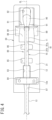
FIG. 2 is a schematic diagram descriptive of one embodiment of the beverage dispensing device according to the one aspect of the present invention, andFIG. 2 illustrates a portion including the beverage dispensing device inFIG. 1 in an enlarged manner and also illustrates a main part in a cutaway manner; -
FIGS. 3A to 3C are explanatory diagrams of the one embodiment of the beverage dispensing device according to the one aspect of the present invention, andFIG. 3A is a schematic side view of the beverage dispensing device inFIG. 1 and illustrates a use state in which a tap head is closed,FIG. 3B illustrates a maintenance state in which the tap head is opened, and theFIG. 3C is a schematic perspective view of the maintenance state inFIG. 3B viewed from an obliquely upper left side; -
FIG. 4 is an explanatory diagram of a tube housing portion of a tap base (a schematic plan view of a portion viewed from the arrow A inFIG. 3B ); -
FIG. 5 is a schematic diagram descriptive of an interlocking relationship among respective portions in accordance with a tilted posture of an operation lever, andFIG. 5 illustrates a state in which the operation lever is positioned at a stop position; -
FIG. 6 is another schematic diagram descriptive of the interlocking relationship among the respective portions in accordance with the tilted posture of the operation lever, andFIG. 6 illustrates a state in which the operation lever is positioned at a dispensing position; -
FIG. 7 is still another schematic diagram descriptive of the interlocking relationship among the respective portions in accordance with the tilted posture of the operation lever, andFIG. 7 illustrates a state in which the operation lever is positioned at a continuous dispensing position; -
FIG. 8 is still another schematic diagram descriptive of the interlocking relationship among the respective portions in accordance with the tilted posture of the operation lever, andFIG. 8 illustrates a state in which the operation lever is positioned at a foaming position; -
FIGS. 9A and 9B are schematic diagrams descriptive of an elastically deformed state of a flexible tube by advancing and retracting motions of an opening/closing piece (a cross section of a main part taken along line X-X inFIG. 2 ), andFIG. 9A illustrates a dispensing state in which the opening/closing piece has retracted andFIG. 9B illustrates a stop state in which the opening/closing piece has advanced; and -
FIGS. 10A and 10B are schematic diagrams descriptive of an elastically deformed state of the flexible tube by advancing and retracting motions of a foam-forming piece (a cross section of a main part taken along line Y-Y inFIG. 2 ), andFIG. 10A illustrates the dispensing state in which the foam-forming piece has retracted andFIG. 10B illustrates a foaming state in which the foam-forming piece has advanced. - One embodiment of the present invention will be described below with reference to the drawings as appropriate.
- An effervescent beverage to be applied to a beverage dispensing device of the present embodiment is an effervescent beverage containing carbon dioxide gas. Although an effervescent beverage of this type is typically beer, examples of the effervescent beverage other than beer include a beer-taste beverage (including low-malt beer, new genre beer, non-alcoholic beer, and the like) and a beverage that is categorized as "other beverages" and that generates foam while being exposed to the air.
- For example, such a beverage is, as an effervescent beverage such as beer, a beverage that preferably has a NIBEM value, which is used as an index value indicating foam-stability characteristics, of 20 or more, more preferably 40 or more, and further more preferably 60 or more. With regard to a measurement method of a NIBEM value, see "Revised BCOJ Beer Analysis Method" (issued by Public Interest Incorporated Foundation Brewing Society of Japan).
- Note that the drawings are schematic. Therefore, it should be noted that relations, ratios, and the like between thicknesses and planar dimensions are different from actual ones, and the drawings include portions having different dimensional relationships and ratios from one another among the drawings.
- In addition, the embodiment, which will be described below, indicates a device and a method to embody the technical idea of the present invention by way of example, and the technical idea of the present invention does not limit the materials, shapes, structures, arrangement, and the like of the constituent components to the embodiment described below.
- First, an overall structure of a beverage server will be described.
- As illustrated in
FIG. 1 , a beverage server 1 of the present embodiment includes a holdingcontainer 3 configured to house, inside the holdingcontainer 3 itself, a barrel 2 in which an effervescent beverage is contained, a gas feeder 4 configured to feed a gas for dispensing (for example, carbon dioxide gas) into the barrel 2, and abeverage dispensing device 100 attached to the holdingcontainer 3 and for switching dispensing of the effervescent beverage via a beverage lead-out path 10, foaming, and stop states of the dispensing and the foaming to one another. The holdingcontainer 3 has an opening/closing door 3b disposed on a side surface of amain body 3a of the holdingcontainer 3, and inside the holdingcontainer 3, a not-illustrated device, such as a cooling unit, for the barrel 2 is arranged. - A
beverage extraction unit 2a is disposed at the center of an upper portion of the barrel 2, and agas feed pipe 4a of the gas feeder 4 is installed to a side portion of thebeverage extraction unit 2a in such a manner that the gas can be fed into the barrel 2. The beverage lead-out path 10 has aconnection tube 13 on the base end side attached to the center of an upper portion of thebeverage extraction unit 2a in an attachable and detachable manner. - The effervescent beverage is pushed out from the
beverage extraction unit 2a of the barrel 2 to the beverage lead-out path 10 by pressure of the gas fed from the gas feeder 4. The beverage lead-out path 10 is installed to lead the effervescent beverage fed out from the barrel 2 by gas pressure to a dispensingspout 5 of thebeverage dispensing device 100. - The
beverage dispensing device 100 of the present embodiment includes atap head 20 on the dispensingspout 5 side and atap base 30 covering an upper portion of thetap head 20. Thetap base 30 has anattachment portion 32 on the base end side of thetap base 30 fixed to a position on the central upper side of the opening/closing door 3b by screwing or the like in an attachable and detachable manner. Because of this configuration, thebeverage dispensing device 100 is attached to a side portion of themain body 3a of the holdingcontainer 3 in a projecting manner. - On an upper portion of the
beverage dispensing device 100, a tiltablyoperable operation lever 70 projects upward from thetap head 20, which enables an operator of the beverage server 1 to tiltably operate theoperation lever 70 from the front of the holdingcontainer 3 by hand. In addition, the operator of the beverage server 1 can access the barrel 2 inside themain body 3a by opening the opening/closing door 3b. - Next, the above-described
beverage dispensing device 100 will be described in more detail. - In the
beverage dispensing device 100 of the present embodiment, a housing structure is formed by placing thetap head 20 on top of thetap base 30 in the vertical direction, as illustrated inFIGS. 2 and3A to 3C . As illustrated inFIG. 2 in which a main part is illustrated in an enlarged manner, the beverage lead-out path 10 is inserted into aninsertion hole 33 in a back surface of theattachment portion 32 attached on the opening/closing door 3b and led from the inside of the above-describedmain body 3a into thebeverage dispensing device 100. - Hereinafter, the longitudinal direction (the right-left direction in
FIG. 2 ) of aflexible tube 11 that passes through the inside of thebeverage dispensing device 100 is referred to as a front-rear direction of the beverage server 1 and thebeverage dispensing device 100, and the operator side (the right-hand side inFIG. 2 ) and an opposite side to the operator side (the left-hand side inFIG. 2 ) are referred to as a front (or a near side) and a rear (or a far side), respectively. In addition, a lateral direction with respect to theflexible tube 11 is also referred to as a right-left direction of thebeverage dispensing device 100. - In the example of the present embodiment, a dispensing
nozzle 90 that extends obliquely downward and forward is arranged at a position of a tip of theflexible tube 11 on a dispensing side of thetap base 30. The dispensingnozzle 90 is formed in a truncated cone shape that has an inner diameter dimension gradually increasing from the base end side toward the tip end side. Theflexible tube 11 is formed of an elastically deformable resin material having flexibility. Theflexible tube 11 is installed to be horizontally housed in thetap base 30 of thebeverage dispensing device 100. - The
flexible tube 11 is bent downward on the dispensing side of thetap base 30, and a tip portion of theflexible tube 11 is connected to the base end portion of the dispensingnozzle 90 serving as the dispensingspout 5, inside thebeverage dispensing device 100. Note that although in the example of the present embodiment, an example in which the dispensingnozzle 90 serving as the dispensingspout 5 is connected to the tip portion of theflexible tube 11 was described, the present invention is not limited to the configuration and the tip portion itself of theflexible tube 11 may be configured to serve as the dispensingspout 5. - The above-described
operation lever 70 is installed on a front-side upper portion of thetap head 20 in such a manner as to be able to slidably move aslide piece 40. Theoperation lever 70 of the present embodiment includes alever shaft 71 and alever body 75 attached to ajoint portion 72 on an upper portion of thelever shaft 71. - At the middle of the
lever shaft 71, a hemispherically-shapedfulcrum portion 73 is formed. In addition, on a lower end portion of thelever shaft 71, anaction portion 74 that has end surfaces in the front-rear direction formed in a spherical shape is formed. Theoperation lever 70 is attached at a central position in a front-side portion of thetap head 20 in such a way that tilting operation in which theoperation lever 70 is tilted in the front-rear direction about thefulcrum portion 73 can be performed. - Inside the
tap head 20, aslide guide portion 25 that allows movement of the above-describedslide piece 40 in a sliding direction and, at the same time, constrains movement of theslide piece 40 in the other directions is formed (seeFIGS. 9A, 9B, 10A and 10B ). - The
slide piece 40 is housed in thetap head 20 in a slidably movable manner in the longitudinal direction of theflexible tube 11 along a guide surface of theslide guide portion 25. Theslide piece 40 has a position thereof in the sliding direction when no operational force is exerted maintained by elastic pressing forces of an opening/closing spring 51 and a foam-formingspring 61 while being housed in theslide guide portion 25. Note that as an optional configuration, it may be configured such that slide springs 41 are disposed in front and rear in the sliding direction of theslide piece 40 and the slide springs 41 restrict the position in the sliding direction of theslide piece 40. - At a position on a front side of an upper surface of the
slide piece 40, afitting groove 42 to engage theoperation lever 70 and theslide piece 40 with each other is formed. Thelever shaft 71 is combined with theslide piece 40 in such a manner that the spherical surface portions on the front and rear sides of theaction portion 74 come into sliding contact with an inner peripheral surface of thefitting groove 42 of theslide piece 40. Because of this configuration, it is configured such that when the operator operates theoperation lever 70 in the front-rear direction in a tilting manner by hand, theslide piece 40 housed in theslide guide portion 25 can slidably move in the front-rear direction along the guide surface of theslide guide portion 25. - The
operation lever 70 of the present embodiment can be tiltably operated among a stop position P0 at which theoperation lever 70 is in a posture in which theoperation lever 70 substantially stands vertically (seeFIG. 5 ), a dispensing position P1 at which theoperation lever 70 is tilted to the front side of the stop position P0 (seeFIG. 6 ), and a foaming position P3 at which theoperation lever 70 is tilted to the rear side of the stop position P0 (seeFIG. 8 ), as described later. Note that in the beverage server 1 of the present embodiment, theoperation lever 70 is also configured to be tiltably operable to a continuous dispensing position P2 at which a dispensing state of the effervescent beverage can be maintained (seeFIG. 7 ). - On an upper portion on the tip end side of the
tap base 30, as illustrated inFIGS. 3A to 3C , afulcrum shaft 23 that has an axis orthogonal to an arrangement direction of theflexible tube 11 is disposed, and at one end of thetap head 20, anaxial support portion 34 that projects downward in such a manner as to fit to thefulcrum shaft 23 in a freely rotatable manner is formed. - The
tap head 20 has theaxial support portion 34 fitted to thefulcrum shaft 23 in the opposing direction and is thereby combined with thetap base 30 in a turnable manner about thefulcrum shaft 23. Because of this configuration, thetap head 20 is configured to be able to be positioned in a use posture in which thetap head 20 is locked on thetap base 30 side (FIG. 3A ) and a maintenance posture in which thetap head 20 is turned upward with respect to the tap base 30 (FIGS. 3B and 3C ). - Note that in the present embodiment, an
engagement claw 24 that is installed in an advanceable and retractable manner by a pressing spring is disposed on thetap head 20 and a recessed portion that is engaged with theengagement claw 24 is also disposed on thetap base 30, and thetap head 20 and thetap base 30 are configured to be opened and closed after the engagement is released by turning theengagement claw 24 for engagement between thetap base 30 and thetap head 20 against the pressing spring of theengagement claw 24. - Contact surfaces of the
tap base 30 and thetap head 20 that face each other are formed as a pair of tube holding surfaces 21 and 31. As illustrated inFIG. 4 , atube holding surface 31 is formed on the internal upper surface side of thetap base 30, and atube housing portion 80 is formed on thetube holding surface 31. Respective parts of thetube housing portion 80 are configured to be able to house the beverage lead-out path 10 along a central line CL of thetube holding surface 31, which extends in the extending direction of the to-be-housedflexible tube 11. - The beverage lead-
out path 10 of the present embodiment is formed including theconnection tube 13, a tube joint 12, and theflexible tube 11. Theflexible tube 11 is connected to the tip end side of theconnection tube 13 via the tube joint 12 in a communicable state in which the effervescent beverage is allowed to pass through an inner cavity of theflexible tube 11. Theconnection tube 13 is connected to an entry side of the tube joint 12 inside thebeverage dispensing device 100 while being horizontally extended before thebeverage dispensing device 100. To an exit side of the tube joint 12, the base end portion of theflexible tube 11 is connected. - The
tap base 30 and thetap head 20 defines a tube storage area that holds the beverage lead-out path 10 including theflexible tube 11 while being in a substantially close contact with an outer surface of the beverage lead-out path 10, inside thebeverage dispensing device 100 by vertically laying the tube holding surfaces 21 and 31 of thetap head 20 and thetap base 30 on top of each other. - In the present embodiment, the respective parts of the
tube housing portion 80 include, in order from the rear side, a connectiontube housing groove 87 configured to house a tip portion of theconnection tube 13, a flangeportion holding portion 84 configured to house aflange portion 12a of the tube joint 12 and ajoint housing portion 83 configured to house a cylindrical main body portion of the tube joint 12 that continue from the connectiontube housing groove 87, and atube holding portion 81 configured to house a to-be-pressed intermediate portion of theflexible tube 11 that continues from thejoint housing portion 83. - The
tube holding portion 81 is formed to hold theflexible tube 11 at a fixed position in thetube housing portion 80 and also stabilize an elastically deformed state of theflexible tube 11 at the time of being pressed by an opening/closinggroove 50 and a foam-formingpiece 60. In particular, thetube holding portion 81 of the present embodiment includes a right-and-left pair of rear-side holding portions 81b and a right-and-left pair of front-side holding portions 81a configured to hold theflexible tube 11 that is in a state of being housed in thetube housing portion 80, by clamping theflexible tube 11 from the right-hand and left-hand sides. Between thejoint housing portion 83 and the rear-side holding portions 81b, an opening/closinggroove 85 formed at a position opposed to the opening/closing piece 50 is formed, and between the rear-side holding portions 81b and the front-side holding portions 81a, a foam-forminggroove 86 formed at a position opposed to the foam-formingpiece 60 is formed. - Further, in the
tube holding portion 81 of the present embodiment, atube guiding surface 88, a pair of holding plate guide surfaces 89 disposed on the right-hand and left-hand sides of thetube guiding surface 88, and anozzle housing hole 82 opening to an end on the dispensing side are disposed on the front side of the front-side holding portions 81a. Thetube guiding surface 88 is formed into a smooth surface that forms a protruding semicircular cross-sectional outline, and maintains a bent state of theflexible tube 11 that is bent downward. - The dispensing
nozzle 90 connected to the tip of theflexible tube 11 has a tip portion thereof on the dispensingspout 5 side inserted into thenozzle housing hole 82, and a loading posture of the dispensingnozzle 90 is maintained while a pair ofnozzle holding plates 91 that project to the right-hand and left-hand sides on the base end side of the dispensingnozzle 90 are guided by the pair of holding plate guide surfaces 89. - The
slide piece 40 in thetap head 20 is arranged above and facing thetube housing portion 80. On an upper surface of the above-describedslide piece 40, twocam grooves fitting groove 42. Between thecam groove 45 and thecam groove 46, amountain portion 44 is formed. - The
slide piece 40 includes thecam groove 45 for the opening/closing piece 50 and thecam groove 46 for the foam-formingpiece 60, which are formed on the upper surface of theslide piece 40, and in a portion of theslide piece 40 including the twocam grooves slot 43 that extends along the sliding direction is formed in a penetrating manner in the vertical direction in such a way that no interfere occurs within a sliding range of theslide piece 40. - Inside the
tap head 20, the opening/closing piece 50 and the foam-formingpiece 60 are disposed in this order from the rear side, andcam follower portions closing piece 50 and the foam-formingpiece 60 are engaged with thecam grooves cam grooves closing piece 50 is advanced and retracted by theslide piece 40 and is thereby capable of opening and closing the inner cavity of theflexible tube 11, and the foam-formingpiece 60 is advanced and retracted by theslide piece 40 and is thereby capable of elastically deforming theflexible tube 11 into a shape suitable for dispensing foam. - More specifically, the opening/
closing piece 50 is a member formed in a substantially T-shape in front view that includes apressing portion 52 and a pair ofcam follower portions 53 that project to the right-hand and left-hand sides from an upper portion of thepressing portion 52. Thecam follower portions 53 form cam followers that protrude downward. Thepressing portion 52 of the opening/closing piece 50 is inserted into the guidingslot 43 from above theslide piece 40 and is loaded in theslide piece 40 while the pair ofcam follower portions 53 are fitted into the rear-side cam groove 45. - In the loaded state, the opening/
closing piece 50 is constantly biased from the upper side toward the lower side in the vertical direction by the opening/closing spring 51, which is a biasing spring. In the present embodiment, the opening/closing piece 50 includes, as an elastic pressingforce adjustment mechanism 54 to adjust elastic pressing force of the opening/closing spring 51, a setscrew and a nut configured to fix a screwing position of the setscrew on top of the opening/closing spring 51 and is configured to be capable of adjusting pressing force exerted by the opening/closing spring 51, using the elastic pressingforce adjustment mechanism 54. - In addition, the foam-forming
piece 60 is a member formed in a substantially T-shape in front view that includes apressing portion 62 and a pair ofcam follower portions 63 that project to the right-hand and left-hand sides from an upper portion of thepressing portion 62. Thecam follower portions 63 form cam followers that protrude downward. Thepressing portion 62 of the foam-formingpiece 60 is inserted into the guidingslot 43 from above theslide piece 40 and is loaded in theslide piece 40 while the pair ofcam follower portions 63 are fitted into the front-side cam groove 46. - In the loaded state, the foam-forming
piece 60 is constantly biased from the upper side toward the lower side in the vertical direction by the foam-formingspring 61, which is a biasing spring. In the present embodiment, the foam-formingpiece 60 includes, as an elastic pressingforce adjustment mechanism 64 to adjust elastic pressing force of the foam-formingspring 61, a setscrew and a nut configured to fix a screwing position of the setscrew on top of the foam-formingspring 61 and is configured to be capable of adjusting pressing force exerted by the foam-formingspring 61, using the elastic pressingforce adjustment mechanism 64. - In this configuration, as illustrated in
FIGS. 10A and 10B , a mechanism to narrow the inner cavity of theflexible tube 11 by advancement and retraction of the foam-formingpiece 60 is configured to cause only one narrowed flow path to be generated in the beverage lead-out path by elastically deforming theflexible tube 11 with the recessedpressing portion 62 of the foam-formingpiece 60. - In particular, a flow path narrowing mechanism for the
flexible tube 11 is configured in a three-point clamping structure that clamps theflexible tube 11 at three points by abottom wall portion 86d of the foam-forminggroove 86 and a right-and-left pair of limitingside wall portions pressing portion 62 of the foam-formingpiece 60 and that face thebottom wall portion 86d in the vertical direction, as illustrated inFIG. 10B . - Further, the
tube housing portion 80 includes thebottom wall portion 86d that pinches theflexible tube 11 in collaboration with the pressing portion of the foam-formingpiece 60, the pair of limitingside wall portions piece 60, and thebottom wall portion 86d and the pair of limitingside wall portions flexible tube 11 at three points at the same time. Note that in construction of the three-point clamping structure, a protruding portion may be formed on a bottom surface of thebottom wall portion 86d. However, when a protruding portion is formed on the bottom surface of thebottom wall portion 86d, stability of foam generation tends to deteriorate. Therefore, in thebeverage dispensing device 100 of the present embodiment, the bottom surface of thebottom wall portion 86d is formed in a flat surface. - Next, operation and advantageous effects of the beverage server 1 and the
beverage dispensing device 100 installed in the beverage server 1 according to the present embodiment will be described. First, maintenance of thebeverage dispensing device 100 and in particular an installation process of the beverage lead-out path 10 will be described. - When maintenance of the
beverage dispensing device 100 of the present embodiment is performed, engagement of theengagement claw 24 between thetap base 30 and thetap head 20 is released, and thetap head 20 is turned to an upper front side about theaxial support portion 34 by hand and thereby brought into an open posture. Through this operation, as illustrated inFIG. 3B , thetap base 30 and thetap head 20 are separated from each other, and thetube housing portion 80 to hold theflexible tube 11 inside thebeverage dispensing device 100 is opened in a visually recognizable manner. - Subsequently, as illustrated in
FIG. 3C , the beverage lead-out path 10 is arranged in thetube housing portion 80, and the tip portion of theflexible tube 11 is inserted into the dispensingnozzle 90 by hand. Since thetube holding portion 81 is formed as a clamping portion on the right-hand and left-hand sides of thetube housing portion 80, theflexible tube 11 inserted into thetube housing portion 80 is, while being clamped from the right and left lateral sides by thetube holding portion 81, led to the base end portion of the dispensingnozzle 90 while a state in which theflexible tube 11 is bent along thetube guiding surface 89 is maintained. - Subsequently, as illustrated in
FIG. 3A , thetap head 20 is turned to a closed posture by hand in such a way that thetap head 20 overlaps thetap base 30. Through this operation, it is possible to pass theflexible tube 11 to a predetermined position in the tube storage area without using an appliance, such as a tool, and, by turning thetap head 20 downward and thereby bringing thetap head 20 into the closed posture, hold the beverage lead-out path 10 including theflexible tube 11. Note that since removal of the beverage lead-out path 10 can be performed in a reverse process to the above-described process, a description thereof will be omitted. - Next, dispensing of the effervescent beverage, dispensing stop, and foaming operation by the
beverage dispensing device 100 will be described with reference toFIGS. 5 to 8 ,9A, 9B, 10A and 10B as appropriate. - First, when no operational force is exerted on the
operation lever 70 of thebeverage dispensing device 100, theoperation lever 70 is positioned at the stop position P0 at which theoperation lever 70 is in a posture in which the axis of theoperation lever 70 stands vertically, as illustrated inFIG. 5 . When theoperation lever 70 is positioned at the stop position P0, thecam follower portion 63 of the foam-formingpiece 60 is fitted into a valley of thecam groove 46 in theslide piece 40, and thecam follower portion 53 of the opening/closing piece 50 is fitted into a valley of thecam groove 45 in theslide piece 40. - Therefore, both the opening/
closing piece 50 and the foam-formingpiece 60 are in a state of having advanced in the opposing direction to theflexible tube 11. On this occasion, both the opening/closing piece 50 and the foam-formingpiece 60 are pressing theflexible tube 11 into expected states with elastic pressing forces of the opening/closing spring 51 and the foam-formingspring 61, respectively. On this occasion, in the example in the present embodiment, the opening/closing piece 50 completely closes a flow path at an opening/closing portion, as illustrated inFIG. 9B . - Note that on this occasion, the foam-forming
piece 60 is brought into a state of having narrowed a flow path at a foam-forming portion of theflexible tube 11 to a predetermined shape, as illustrated inFIG. 10B . Through this operation, a dispensing stop state of the effervescent beverage is maintained. In addition, the elastic pressing forces of the opening/closing spring 51 and the foam-forming spring 61 (when the slide springs 41 are installed, the elastic pressing forces obtained by adding elastic pressing forces of the slide springs 41 to the elastic pressing forces of the opening/closing spring 51 and the foam-forming spring 61) are balanced, and theoperation lever 70 is self-standing in a neutral posture in which the axis of theoperation lever 70 is vertical. - Next, in the beverage server 1 of the present embodiment, when the operator pours the effervescent beverage into a glass, the operator presses the
operation lever 70 toward the near side when viewed from the operator side (the rightward direction inFIG. 6 ) by hand from the neutral posture until theoperation lever 70 reaches a first forward tilting posture (the dispensing position P1), as illustrated inFIG. 6 . - When an operational force tilting forward the
operation lever 70 until theoperation lever 70 reaches the first forward tilting posture is exerted, theslide piece 40 moves rearward (the leftward direction inFIG. 6 ) to a position corresponding to the first forward tilting posture by the operational force. In association with the movement, by action of the above-described cam, the protrusion-shaped cam follower of the opening/closing piece 50 moves along a front-side cam surface of thecam groove 45 of theslide piece 40 to above an intermediate portion of the front-side cam surface, and the flow path at the opening/closing portion is opened, as illustrated inFIG. 9A . Further, the protrusion-shaped cam follower of the foam-formingpiece 60 moves upward along a front-side cam surface of thecam groove 45 of theslide piece 40 to an intermediate portion of the front-side cam surface, and the flow path at the foam-forming portion is also opened, as illustrated inFIG. 10A . Through this operation, the operator can pour the effervescent beverage into a glass. - In the beverage server 1 of the present embodiment, the
operation lever 70 is configured to be tiltably operable to a second forward tilting posture by exerting an operational force tilting theoperation lever 70 to the front side of the above-described first forward tilting posture, as illustrated inFIG. 7 . - When the
operation lever 70 is in the second forward tilting posture, theoperation lever 70 is positioned at the continuous dispensing position P2 at which the dispensing state of the effervescent beverage is maintained. In other words, when the operator pours the effervescent beverage into a large-size container, such as a pitcher, the operator further presses theoperation lever 70 from the dispensing position P1 to the near side when viewed from the operator side (the rightward direction inFIG. 7 ) by hand (the continuous dispensing position P2), as illustrated inFIG. 7 . - Through this operation, the
slide piece 40 moves farther rearward (the leftward direction inFIG. 7 ) in accordance with the second forward tilting posture. In association with the movement, the protrusion-shaped cam follower of the opening/closing piece 50 climbs over the front-side cam surface of thecam groove 45 of theslide piece 40 and reaches themountain portion 44, and is pressed against a horizontal plane on the top of themountain portion 44. - In the pressed state, the elastic pressing forces of the opening/
closing spring 51 and the foam-forming spring 61 (when the slide springs 41 are installed, the elastic pressing forces obtained by adding the elastic pressing forces of the slide springs 41 to the elastic pressing forces of the opening/closing spring 51 and the foam-forming spring 61) are configured to be balanced, and when no operational force is exerted on theoperation lever 70, a tilted posture of the theoperation lever 70 is maintained. Through this operation, until theoperation lever 70 is returned from the continuous dispensing position P2 to the stop position P0 at which theoperation lever 70 is in a neutral posture by further exerting an operational force on theoperation lever 70, the dispensing state of the effervescent beverage is maintained, and the operator can continuously pour the effervescent beverage into a large-size container, such as a pitcher. - Next, when in the beverage server 1 of the present embodiment, the operator performs foaming in the glass, the operator presses the
operation lever 70 of thebeverage dispensing device 100 toward the far side when viewed from the operator side (the leftward direction inFIG. 8 ) by hand (the foaming position P3) from the neutral posture, as illustrated inFIG. 8 . Through this operation, theslide piece 40 moves forward (the rightward direction inFIG. 8 ). In association with the movement, the protrusion-shaped cam follower of the opening/closing piece 50 moves upward along a rear-side cam surface of thecam groove 45 of theslide piece 40, and the flow path at the opening/closing portion of theflexible tube 11 is opened, as illustrated inFIG. 9A . - Further, the protrusion-shaped cam follower of the foam-forming
piece 60 is brought into a pressed state in which the protrusion-shaped cam follower is restricted by a rear-side cam surface of thecam groove 46 of theslide piece 40, and the flow path at the foam-forming portion of theflexible tube 11 is narrowed to a predetermined shape, as illustrated inFIG. 10B . - In particular, in the present embodiment, the flow path narrowing mechanism based on advancement and retraction of the foam-forming
piece 60 causes only one narrowed flow path to be generated in the beverage lead-out path 10 by elastically deforming theflexible tube 11 by the opposing recessedpressing portion 62 of the foam-formingpiece 60 at a position at which theflexible tube 11 is held in the recessed housing portions of the front-side holding portions 81a and the rear-side holding portions 81b. Because of this configuration, it is possible to generate foam by narrowing cross-sectional area of the inner cavity in the tube and thereby causing an orifice to be generated and perform desired foaming. - As described above, according to the
beverage dispensing device 100 of the present embodiment, the opening/closing piece 50 can open and close theflexible tube 11 only with elastic pressing force of the opening/closing spring 51 by advancing and retracting operation with respect to theflexible tube 11 that is converted by action of a cam associated with sliding movement of theslide piece 40 in accordance with tilting operation of theoperation lever 70. Likewise, the foam-formingpiece 60 can form foam by narrowing theflexible tube 11 only with elastic pressing force of the foam-formingspring 61 by advancing and retracting operation with respect to theflexible tube 11 that is converted by action of a cam associated with the sliding movement of theslide piece 40 in accordance with the tilting operation of theoperation lever 70. - In other words, in the
beverage dispensing device 100 of the present embodiment, since a pressure control system based on pressing force only by spring pressure of the biasing springs 51 and 61 is employed, it is possible to perform pressing with a stable pressing force that is constantly uniform. Therefore, unlike the technology described in PTL 1 described above by way of example, it is possible to stabilize the cross-sectional area of the inner cavity of theflexible tube 11 after deformation to a substantially constant area without depending on adjustment of force by the operator. - Thus, according to the
beverage dispensing device 100 and the beverage server 1 including thebeverage dispensing device 100 according to the present embodiment, thebeverage dispensing device 100 and the beverage server 1 excel in manual operability, facilitate adjustment of foam quality, and provide high reproducibility of adjusted foam quality. Therefore, it is possible to pour an effervescent beverage, such as beer, having a stable foam quality (Claims 1 and 13). - Note that although in the present embodiment, a configuration example in which the
operation lever 70 is configured to be able to slidably move theslide piece 40 in accordance with tilting operation of theoperation lever 70 was described, with regard to the manual operability, various forms of theoperation lever 70 can be employed as long as theoperation lever 70 is a lever that is manually operable without being limited to tilting operation. For example, theoperation lever 70 may also be configured to slidably move, and theslide piece 40 may be configured to be slidably movable in accordance with the sliding movement of theoperation lever 70. - In addition, according to the
beverage dispensing device 100 of the present embodiment, theoperation lever 70 is configured to be tiltably operable to the stop position P0 at which dispensing of the effervescent beverage and foaming are stopped, the dispensing position P1 at which the effervescent beverage is dispensed, and the foaming position P3 at which foam of the effervescent beverage is generated and dispensed, and when theoperation lever 70 is positioned at the stop position P0, a cam mechanism causes the opening/closing piece 50 and the foam-formingpiece 60 to be positioned at an advanced position with respect to theflexible tube 11. - It is also possible to set the foam-forming
piece 60 to a retracted position when theoperation lever 70 is positioned at the stop position P0, as in, for example, the technology described in PTL 1. - However, setting the foam-forming
piece 60 to an advanced position when theoperation lever 70 is positioned at the stop position P0 as in the present embodiment enables foaming to be performed immediately after tilting operation of theoperation lever 70 toward the foaming position P3 is started. - This is because since when the former setting is performed, the opening/
closing piece 50 is required to be retracted after the foam-formingpiece 60 is moved to an advanced position, a time lag occurs in the foaming with respect to the tilting operation of theoperation lever 70. In addition, there is a problem in that when the opening/closing piece 50 is retracted at the same time as the foam-formingpiece 60 advances, foam quality immediately after tilting operation of theoperation lever 70 deteriorates. - Further, the cam mechanism of the present embodiment causes the opening/
closing piece 50 and the foam-formingpiece 60 to be positioned at retracted positions with respect to theflexible tube 11 when theoperation lever 70 is positioned at the dispensing position P1, and causes the opening/closing piece 50 to be positioned at a retracted position with respect to theflexible tube 11 and also causes the foam-formingpiece 60 to be positioned at an advanced position with respect to theflexible tube 11 when theoperation lever 70 is positioned at the foaming position P3. Therefore, according to thebeverage dispensing device 100 of the present embodiment, thebeverage dispensing device 100 is suitable for achieving a small-size, compact beverage dispensing device while maintaining excellent operability similar to operability of a conventional manual-type beverage dispensing device through smooth interlocking operation between the tilting operation of theoperation lever 70 and action of the cam mechanism in accordance with the tilting operation (Claim 2). - In particular, according to the
beverage dispensing device 100 of the present embodiment, since thebeverage dispensing device 100 is configured to perform tilting operation in which theoperation lever 70 is positioned at the stop position P0 at which theoperation lever 70 is in a posture in which the axis of theoperation lever 70 stands vertically when no operational force is exerted on theoperation lever 70, positioned at the dispensing position P1 when an operational force tilting theoperation lever 70 forward is exerted on theoperation lever 70 and theoperation lever 70 is in the first forward tilting posture, and positioned at the foaming position P3 when an operational force tilting theoperation lever 70 rearward is exerted on theoperation lever 70 and theoperation lever 70 is in a rearward tilting posture, thebeverage dispensing device 100 is suitable for, while maintaining excellent operability similar to operability of a conventional manual-type beverage dispensing device, achieving a small-size, compact beverage dispensing device (Claim 3). - Further, in the
beverage dispensing device 100 of the present embodiment, theoperation lever 70 is configured to be tiltably operable to the continuous dispensing position P2 at which the dispensing state of the effervescent beverage is maintained, as illustrated inFIG. 7 , and the cam mechanism is capable of maintaining the tilted posture of theoperation lever 70 unless an operational force is exerted on theoperation lever 70 when theoperation lever 70 is positioned at the continuous dispensing position P2. Therefore, according to thebeverage dispensing device 100 of the present embodiment, since the tilted posture of theoperation lever 70 is maintained and it is possible to not only pour the effervescent beverage into a glass but also continuously pour the effervescent beverage into a large-size container, such as a pitcher, thebeverage dispensing device 100 further excels in convenience (Claim 4). - In addition, in the
beverage dispensing device 100 of the present embodiment, thecam groove 46 for the foam-formingpiece 60 has a cam profile (a bottom surface of a valley) in the sliding movement direction set wider (longer) than thecam groove 45 for the opening/closing piece 50 to maintain non-operating state of the foam-formingpiece 60 in the sliding movement direction longer than the opening/closing piece 50 as action of a cam associated with sliding movement of theslide piece 40 when theoperation lever 70 is operated to the foaming position P3, as illustrated inFIG. 8 . - Therefore, according to the
beverage dispensing device 100 of the present embodiment, it is possible to generate foam even when theoperation lever 70 has not been fully tilted to the far end (a state in which thebeverage flow path 10 has not been completed opened). In other words, it is possible to generate foam from a time point at which a tilt angle of theoperation lever 70 from the neutral posture is smaller. Since because of this configuration, it becomes possible to perform finer adjustment of foaming speed (amount) according to a tilt angle of the operation lever and a foaming adjustment range with respect to the tilt angle of theoperation lever 70 can be expanded, it becomes easier to adjust the foaming speed (amount) (Claim 5). - In addition, according to the
beverage dispensing device 100 of the present embodiment, since, as illustrated inFIG. 2 , thebeverage dispensing device 100 includes the elastic pressing force adjustment mechanisms (54 and 64) to adjust elastic pressing forces of the biasing springs (51 and 61) by the opening/closing piece 50 and the foam-formingpiece 60, respectively, pressing force of each of the opening/closing piece 50 and the foam-formingpiece 60 can be individually adjusted. Therefore, thebeverage dispensing device 100 of the present embodiment is suitable for facilitating adjustment of a dispensing amount of the effervescent beverage and foam quality and further increasing reproducibility of the adjusted dispensing amount and foam quality (Claim 6). - When the hollow cylindrical
flexible tube 11 is simply pressed from the vertical direction, a cross section of the inner cavity of the tube after deformation becomes an ellipse that is flat in the lateral direction. Therefore, the cross section of the inner cavity of the flat elliptical shape after deformation largely changes due to a slight difference in a pressing amount by a pressing member that performs pressing from above or a slight dimensional error of the tube, and in some cases, the flow path is closed. - In addition, in a pressing method, such as the technology described in PTL 1, that generates two or more narrowed flow paths in the beverage lead-out path, shape reproducibility of the two or more narrowed flow paths is lower than a case where only one narrowed flow path is generated, adjustment of foam quality is comparatively difficult, and it is also comparatively difficult to increase reproducibility of adjusted foam quality. In particular, in the case of a pressing method such as the technology described in PTL 1, when a dimensional error of the tube and a resin component is large, a problem, such as no foam being formed, is likely to occur, and influence of a dimensional error on foam quality is large.
- In contrast, according to the
beverage dispensing device 100 of the present embodiment, since the mechanism to narrow the inner cavity by advancement and retraction of the foam-formingpiece 60 elastically deforms theflexible tube 11 by the recessedpressing portions piece 60 and thereby causes only one narrowed flow path to be generated in the inner cavity of theflexible tube 11, as illustrated inFIGS. 10A and 10B , thebeverage dispensing device 100 is suitable for facilitating adjustment of the foam quality and increasing reproducibility of the adjusted foam quality (Claim 7). - In particular, in the
beverage dispensing device 100 of the present embodiment, the flow path narrowing mechanism for theflexible tube 11 employs the three-point clamping structure that clamps theflexible tube 11 at three points by thebottom wall portion 86d of thetube housing portion 80 and the right-and-left pair of limitingside wall portions pressing portion 62 and that face thebottom wall portion 86d in the vertical direction, as illustrated inFIG. 10B . - Because of this configuration, according to the
beverage dispensing device 100 of the present embodiment, the cross-sectional area of the inner cavity of the tube after pressing deformation from the vertical direction can be stabilized to a substantially constant area regardless of the pressing amount and dimensional error of the tube. Since therefore, thebeverage dispensing device 100 of the present embodiment excels in manual operability, facilitates adjustment of foam quality, and provides high reproducibility of adjusted foam quality, thebeverage dispensing device 100 extremely excels in forming foam having stable quality. - In addition, according to the
beverage dispensing device 100 of the present embodiment, since thebeverage dispensing device 100 includes thetube holding portion 81 configured to hold theflexible tube 11 in a recessed housing portion, the position of theflexible tube 11 at the opposing position to the foam-formingpiece 60 can be securely held. - In particular, since the
tube holding portion 81 of the present embodiment includes the front-side holding portions 81a configured to hold theflexible tube 11 in a recessed housing portion at a position on the front side of the foam-formingpiece 60 in the extending direction of theflexible tube 11 and the rear-side holding portions 81b separated from the front-side holding portions 81a in the sliding direction and configured to hold theflexible tube 11 in a recessed housing portion at a position on the rear side of the foam-formingpiece 60, thetube holding portion 81 is capable of securely holding theflexible tube 11 at a position in the vicinity of the foam-formingpiece 60 in the front-rear direction. - Further, since in the
beverage dispensing device 100 of the present embodiment, the front-side holding portions 81a and the rear-side holding portions 81b are configured such that length in the sliding direction (in other words, the extending direction of the flexible tube 11) of a holding portion in the front-side holding portions 81a is shorter than length in the sliding direction of a holding portion in the rear-side holding portions 81b, this configuration, while enabling theflexible tube 11 to be securely held at a position in the vicinity of the foam-formingpiece 60 in the front-rear direction, enables pipe length on the dispensing side to be short as much as possible. Therefore, thebeverage dispensing device 100 of the present embodiment is suitable for facilitating adjustment of foam quality and forming foam having a high reproducibility of an adjusted foam quality and stable quality (Claim 8). - In addition, according to the
beverage dispensing device 100 of the present embodiment, since the beverage lead-out path 10 is configured to be easily insertable and removable into and from thetube housing portion 80 by hand, no special tool and no special component for fixing is required and thebeverage dispensing device 100 excels in maintainability in replacement and loading work of the beverage lead-out path 10 (Claim 9). - In particular, in the present embodiment, since the beverage lead-
out path 10 is formed including theflexible tube 11, theconnection tube 13 connected to the barrel 2 side, and the tube joint 12 configured to join theconnection tube 13 andflexible tube 11, as illustrated inFIG. 4 , the respective constituent components, that is, the flexible tube, the connection tube, and the tube joint, can be individually removed and maintained. Note that the beverage lead-out path 10 may be integrated into one component and may have a configuration in which respective constituent parts cannot be removed. However, since the beverage lead-out path 10 is more likely to become dirty toward the tip end (since temperature is high), it is preferable to configure the beverage lead-out path 10 in such a way that theflexible tube 10 and subsequent components can be removed and replaced. - Since the
tube housing portion 80 is formed by the connectiontube housing groove 87 configured to house theconnection tube 13, the joint housing portion configured to house the tube joint 12, and thetube holding portion 81 configured to house and hold theflexible tube 11 in this order from the rear side, thetube housing portion 80 is suitable for securely holding the respective constituent parts of the beverage lead-out path 10 at expected positions. - In addition, according to the
beverage dispensing device 100 of the present embodiment, a housing structure is formed by placing thetap head 20 on top of the thetap base 30 in the vertical direction, as illustrated inFIG. 2 . Further, theflexible tube 11 can be installed by hand in such a way that theflexible tube 11 is horizontally housed along the front-rear direction in thetube housing portion 80 that is formed in thetap base 30 and configured to hold theflexible tube 11 in the recessed housing portion. - Since the
slide piece 40 is housed inside thetap head 20 in a slidably movable manner along the longitudinal direction of theflexible tube 11 in thetube housing portion 80 and theoperation lever 70 is installed projecting upward on a front-side upper portion of thetap head 20 in such a manner as to be able to slidably operate theslide piece 40 by tilting operation in the front-rear direction, theslide piece 40 and theoperation lever 70 are suitable as a structure that enables a low cost to be achieved and that excels in maintainability by forming the housing and main components with as small a number of components as possible (Claim 10). - Further, according to the
beverage dispensing device 100 of the present embodiment, since, as illustrated inFIGS. 3A to 3C , thefulcrum shaft 23 having an axis orthogonal to the front-rear direction is disposed on the front side of thetap base 30 and thetap head 20 is joined to thetap base 30 in an openable and closable manner with respect to thetap base 30 by turning motion about thefulcrum shaft 23 and configured to be able to be positioned to a use posture in which thetap head 20 is locked on thetap base 30 side and a maintenance posture in which thetap head 20 is turned upward with respect to thetap base 30, thebeverage dispensing device 100 excels in maintainability for the beverage lead-out path 10 including theflexible tube 11. - In particular, according to the
beverage dispensing device 100 of the present embodiment, since it is configured such that when thetap head 20 is in the use posture, thebeverage dispensing device 100 holds the tube joint 12 between thetap base 30 and thetap head 20 and when thetap head 20 is in the maintenance posture, thetap head 20 is turned to a position at which the entire beverage lead-out path 10 can be visually recognized in thetube housing portion 80 on an upper surface of thetap base 30 and the beverage lead-out path 10 is insertable and removable into and from thetube housing portion 80 without using a tool, it can be said that thebeverage dispensing device 100 extremely excels in maintainability of the beverage lead-out path 10 including the flexible tube 11 (Claim 11). - In addition, according to the
beverage dispensing device 100 of the present embodiment, since the beverage lead-out path 10 further includes the dispensingnozzle 90, as also illustrated inFIGS. 3A to 3C and4 and the dispensingnozzle 90 is formed in a truncated cone shape that has inner diameter dimension gradually increasing from the base end side toward the tip end side, thebeverage dispensing device 100 is suitable for preventing foam from being generated at the time of beverage dispensing. - In other words, when the inner diameter of the
flexible tube 11 is too small for flow velocity, flow of beverage dispensed from the dispensingspout 5 becomes unstable and foam is likely to be formed when the beverage is poured into a glass. Therefore, in thebeverage dispensing device 100 of the present embodiment, the flow of beverage is straightened by installing the dispensingnozzle 90 the inner diameter of which is gradually increased and foam forming at the time of dispensing beverage is thereby prevented. - In addition, according to the
beverage dispensing device 100 of the present embodiment, since it is configured such that when thetap head 20 is in the use posture, thebeverage dispensing device 100 presses and holds the dispensing nozzle 90 (in this example, a portion placed on the nozzle holding plate 91) between thetap base 30 and thetap head 20 and when thetap head 20 is in the maintenance posture, the beverage lead-out path 10 including the dispensingnozzle 90 is insertable and removable into and from thetube housing portion 80 without using a tool, thebeverage dispensing device 100 is more suitable as a structure that excels in maintainability (Claim 12). - As described in the foregoing, according to the
beverage dispensing device 100 and the beverage server 1 including thebeverage dispensing device 100 according to the present embodiment, thebeverage dispensing device 100 and the beverage server 1 excel in manual operability, facilitates adjustment of foam, and provides high reproducibility of adjusted foam quality. - Note that the beverage dispensing device and the beverage server including the beverage dispensing device according to the present invention are not limited to the above-described embodiment, and it is needless to say that various modification can be made without departing from the spirit and scope of the present invention.
-
- 1 Beverage server
- 2 Barrel
- 2a Beverage extraction unit
- 3 Holding container
- 3a Main body
- 3b Opening/closing door
- 4 Gas feeder
- 4a Gas feed pipe
- 5 Dispensing spout
- 10 Beverage lead-out path
- 11 Flexible tube
- 12 Tube joint
- 13 Connection tube
- 20 Tap head
- 21 Tube holding surface (on the tap head side)
- 22 Nozzle holding arm
- 23 Fulcrum shaft
- 24 Engagement claw
- 25 Slide guide portion
- 30 Tap base
- 31 Tube holding surface (on the tap base side)
- 32 Attachment portion
- 33 Insertion hole
- 34 Axial support portion
- 40 Slide piece
- 41 Slide spring
- 42 Fitting groove
- 43 Guiding slot
- 44 Mountain portion
- 45 Cam groove
- 46 Cam groove
- 50 Opening/closing piece
- 51 Opening/closing spring (biasing spring)
- 52 Pressing portion
- 53 Cam follower portion
- 54 Elastic pressing force adjustment mechanism
- 60 Foam-forming piece
- 61 Foam-forming spring (biasing spring)
- 62 Pressing portion
- 63 Cam follower portion
- 64 Elastic pressing force adjustment mechanism
- 70 Operation lever
- 71 Lever shaft
- 72 Joint portion
- 73 Fulcrum portion
- 74 Action portion
- 75 Lever body
- 80 Tube housing portion
- 81 Tube holding portion
- 81a Front-side holding portion
- 81b Rear-side holding portion
- 82 Nozzle housing hole
- 83 Joint housing portion (recessed housing portion)
- 84 Flange portion holding portion (recessed housing portion)
- 85 Opening/closing groove
- 86 Foam-forming groove
- 87 Connection tube housing groove (recessed housing portion)
- 88 Tube guiding surface
- 89 Holding plate guide surface
- 90 Dispensing nozzle
- 91 Nozzle holding plate
- 100 Beverage dispensing device
- P0 Stop position
- P1 Dispensing position
- P2 Continuous dispensing position
- P3 Foaming position
Claims (13)
- A beverage dispensing device switchable among dispensing of an effervescent beverage, dispensing stop, and foaming by opening and closing an inner cavity of a flexible tube in accordance with operation by an operator, the beverage dispensing device comprising:an operation lever operable by an operator to a dispensing position to dispense the effervescent beverage, a foaming position to dispense foam of the effervescent beverage, and a stop position to stop dispensing of the effervescent beverage and foaming;a slide piece configured to slidably move in a front-rear direction in association with operation of the operation lever;an opening/closing piece configured to open and close the inner cavity by advancing and retracting in an opposing direction to the flexible tube by action of a cam associated with sliding movement of the slide piece in accordance with operation of the operation lever and pressing the flexible tube only with elastic pressing force of a biasing spring; anda foam-forming piece configured to form foam by advancing and retracting in an opposing direction to the flexible tube at a position on a dispensing side of the opening/closing piece by action of a cam associated with sliding movement of the slide piece in accordance with operation of the operation lever, pressing the flexible tube only with elastic pressing force of a biasing spring, and narrowing the inner cavity.
- The beverage dispensing device according to claim 1, whereina mechanism of the camwhen the operation lever is positioned at the stop position, positions the opening/closing piece and the foam-forming piece at an advanced position with respect to the flexible tube,when the operation lever is positioned at the dispensing position, positions the opening/closing piece and the foam-forming piece at a retracted position with respect to the flexible tube, andwhen the operation lever is positioned at the foaming position, positions the opening/closing piece at a retracted position with respect to the flexible tube and positions the foam-forming piece at an advanced position with respect to the flexible tube.
- The beverage dispensing device according to claim 2, whereinthe operation lever is configured to be tiltably operable along the sliding direction and, when in the sliding direction, a dispensing side of the effervescent beverage is assumed to be a front and an opposite side to the dispensing side is assumed to be a rear,when no operational force is exerted on the operation lever, is positioned at the stop position at which the operation lever is in a posture in which an axis of the operation lever stands vertically,when an operational force tilting the operation lever to a front side is exerted on the operation lever and the operation lever is in a first forward tilting posture, is positioned at the dispensing position, andwhen an operational force tilting the operation lever to a rear side is exerted on the operation lever and the operation lever is in a rearward tilting posture, is positioned at the foaming position.
- The beverage dispensing device according to claim 3, whereinthe operation lever is configured to be tiltably operable to a second forward tilting posture by an operational force, the operational force tilting the operation lever to a front side of the first forward tilting posture, being exerted on the operation lever and, when the operation lever is in the second forward tilting posture, is positioned at a continuous dispensing position at which a dispensing state of the effervescent beverage is maintained, anda mechanism of the cam, when the operation lever is positioned at the continuous dispensing position, positions the opening/closing piece and the foam-forming piece at retracted positions with respect to the flexible tube and, when no operational force is exerted on the operation lever, maintains the retracted positions.
- The beverage dispensing device according to claim 2, whereinthe slide piece includes a cam groove for an opening/closing piece, the cam groove being formed on an upper surface of the slide piece, and a cam groove for a foam-forming piece, the cam groove being formed on the upper surface of the slide piece,each of cam follower portions of the opening/closing piece and the foam-forming piece is engaged with one of the cam grooves in an advanceable and retractable manner along an inclination of a cam surface of the cam groove, anda cam groove for the foam-forming piece has a cam profile set longer than a cam groove for the opening/closing piece in such a way that when the operation lever is operated to the foaming position, the cam groove for the foam-forming piece maintains a non-operating state of the foam-forming piece in a sliding movement direction longer than the opening/closing piece, as action of a cam associated with sliding movement of the slide piece.
- The beverage dispensing device according to claim 1 further including an elastic pressing force adjustment mechanism configured to adjust elastic pressing force of the biasing spring by the opening/closing piece or the foam-forming piece.
- The beverage dispensing device according to claim 1, wherein a mechanism to narrow the inner cavity by advancement and retraction of the foam-forming piece elastically deforms the flexible tube with a recessed pressing portion of the foam-forming piece and causes only one narrowed flow path to be generated in the inner cavity of the flexible tube.
- The beverage dispensing device according to claim 1 includinga tube housing portion including a recessed housing portion configured to house the flexible tube along the sliding direction and a tube holding portion configured to house and hold the flexible tube,wherein when it is assumed that in the sliding direction, a dispensing side of the effervescent beverage with respect to a position at which the foam-forming piece advances and retracts to and from the flexible tube is a front and an opposite side to the dispensing side is a rear,the tube holding portion includes a front-side holding portion configured to hold the flexible tube in a recessed housing portion at a position on a front side of the foam-forming piece and a rear-side holding portion separated from the front-side holding portion in the sliding direction and configured to hold the flexible tube in a recessed housing portion at a position on a rear side of the foam-forming piece, andthe front-side holding portion and the rear-side holding portion are configured such that length in the sliding direction of a holding portion in the front-side holding portion is shorter than that of the rear-side holding portion.
- The beverage dispensing device according to claim 8, whereinthe beverage dispensing device uses a beverage lead-out path formed by the flexible tube, a connection tube connected to a barrel side, the barrel containing the effervescent beverage, and a tube joint configured to join the connection tube and the flexible tube, andthe tube housing portion includes a connection tube housing groove configured to house the connection tube, a joint housing portion configured to house the tube joint, and the tube holding portion configured to house and hold the flexible tube in this order from a rear side.
- The beverage dispensing device according to claim 1 including:a tap base; and a tap head covering an upper portion of the tap base,wherein a housing structure is formed by placing the tap head on top of the tap base in a vertical direction,the flexible tube is housed in a tube housing portion inside the tap base along a sliding direction of the slide piece and horizontally,the slide piece is installed inside the tap head in a slidably movable manner in a longitudinal direction of the flexible tube housed in the tube housing portion, andthe operation lever is installed projecting upward on a front-side upper portion of the tap head to be able to slidably operate the slide piece by tilting operation in the sliding direction.
- The beverage dispensing device according to claim 10, whereinon a front side of the tap base, a fulcrum shaft having an axis orthogonal to the sliding direction is disposed, andthe tap headis joined to the tap base in an openable and closable manner with respect to the tap base by turning motion about the fulcrum shaft and is configured to be positionable to a use posture in which the tap head is locked on the tap base side and a maintenance posture in which the tap head is turned upward with respect to the tap base,when being in the use posture, holds the flexible tube in the tube housing portion between the tap base and the tap head, andwhen being in the maintenance posture, is turned to a position at which the entire flexible tube can be visually recognized in the tube housing portion and makes the flexible tube insertable and removable into and from the tube housing portion.
- The beverage dispensing device according to claim 11, whereinthe beverage dispensing device further uses a dispensing nozzle connected to a tip of the flexible tube,when the tap head is in the use posture, the beverage dispensing device presses and holds the dispensing nozzle between the tap base and the tap head, andwhen the tap head is in the maintenance posture, the beverage dispensing device is configured such that the dispensing nozzle is insertable and removable into and from the tube housing portion.
- A beverage server comprising the beverage dispensing device according to any one of claims 1 to 12.
Applications Claiming Priority (2)
| Application Number | Priority Date | Filing Date | Title |
|---|---|---|---|
| JP2022094495A JP2023180854A (en) | 2022-06-10 | 2022-06-10 | Beverage dispensing device and beverage server equipped with the same |
| PCT/JP2023/016961 WO2023238554A1 (en) | 2022-06-10 | 2023-04-28 | Beverage dispensing device and beverage server provided with same |
Publications (2)
| Publication Number | Publication Date |
|---|---|
| EP4538220A1 true EP4538220A1 (en) | 2025-04-16 |
| EP4538220A4 EP4538220A4 (en) | 2026-04-15 |
Family
ID=89118092
Family Applications (1)
| Application Number | Title | Priority Date | Filing Date |
|---|---|---|---|
| EP23819541.6A Pending EP4538220A4 (en) | 2022-06-10 | 2023-04-28 | DRINKS DISPENSER AND DRINKS SERVER SO THAT |
Country Status (4)
| Country | Link |
|---|---|
| EP (1) | EP4538220A4 (en) |
| JP (1) | JP2023180854A (en) |
| AU (1) | AU2023284181A1 (en) |
| WO (1) | WO2023238554A1 (en) |
Family Cites Families (6)
| Publication number | Priority date | Publication date | Assignee | Title |
|---|---|---|---|---|
| US4037817A (en) * | 1975-10-28 | 1977-07-26 | Tomlinson Industries, Inc. | Pinch tube valve |
| DE69840304D1 (en) * | 1997-09-04 | 2009-01-15 | Heineken Tech Services | Soda Fountain |
| US8678247B2 (en) * | 2011-03-31 | 2014-03-25 | Lancer Corporation | Creamy foam beer dispensing system |
| WO2017208808A1 (en) * | 2016-06-02 | 2017-12-07 | キリン株式会社 | Beverage foam tap device and beverage server using same |
| JP7204191B2 (en) * | 2018-12-28 | 2023-01-16 | フジテクノ株式会社 | Effervescent beverage dispenser |
| JP2022174658A (en) * | 2021-05-11 | 2022-11-24 | アサヒビール株式会社 | Beverage dispensing device, beverage extraction method and beverage dispensing system |
-
2022
- 2022-06-10 JP JP2022094495A patent/JP2023180854A/en active Pending
-
2023
- 2023-04-28 AU AU2023284181A patent/AU2023284181A1/en active Pending
- 2023-04-28 EP EP23819541.6A patent/EP4538220A4/en active Pending
- 2023-04-28 WO PCT/JP2023/016961 patent/WO2023238554A1/en not_active Ceased
Also Published As
| Publication number | Publication date |
|---|---|
| JP2023180854A (en) | 2023-12-21 |
| WO2023238554A1 (en) | 2023-12-14 |
| AU2023284181A1 (en) | 2024-12-05 |
| EP4538220A4 (en) | 2026-04-15 |
Similar Documents
| Publication | Publication Date | Title |
|---|---|---|
| US4555085A (en) | Lockable tilting apparatus for chair seats | |
| JP4990130B2 (en) | Tap unit for beverage dispenser | |
| JP5413950B2 (en) | Dispensing device and faucet | |
| AU2023284181A1 (en) | Beverage dispensing device and beverage server provided with same | |
| KR20220047720A (en) | training bench | |
| KR101599519B1 (en) | Spray apparatus of liquid substance | |
| CN116568388A (en) | carbonator with boot assembly | |
| JP6578059B2 (en) | Beverage foam pouring device and beverage server using the same | |
| JP2025146986A (en) | Beverage dispensing device, beverage dispensing method, and beverage dispensing system | |
| KR20190084108A (en) | Drinking cocks, valve rod and beverage dispenser | |
| CN104493385B (en) | The fixture of clamping welding mould | |
| JP2018122897A (en) | Discharge device | |
| CN211083401U (en) | Stabilizer is with expanding device and stabilizer | |
| JP3498236B2 (en) | Water spout stand | |
| US12576423B2 (en) | Dispenser | |
| CN114809206B (en) | An easy-to-install device | |
| EP1238854A1 (en) | Holding device for beverage containers in automotive vehicles | |
| JP2007014962A (en) | Nut feeder | |
| CN213204339U (en) | Novel height adjusting device of water inlet valve | |
| CN120284118A (en) | Beverage dispensing head and associated beverage dispensing machine | |
| JP2573064B2 (en) | Ball valve | |
| CN120284119A (en) | Beverage dispensing head and associated beverage dispensing machine | |
| JPS5927251Y2 (en) | Liquid container spout device | |
| KR100576756B1 (en) | Operation structure of gas cylinder operated by cable | |
| JP4777698B2 (en) | Needle threader |
Legal Events
| Date | Code | Title | Description |
|---|---|---|---|
| STAA | Information on the status of an ep patent application or granted ep patent |
Free format text: STATUS: THE INTERNATIONAL PUBLICATION HAS BEEN MADE |
|
| PUAI | Public reference made under article 153(3) epc to a published international application that has entered the european phase |
Free format text: ORIGINAL CODE: 0009012 |
|
| STAA | Information on the status of an ep patent application or granted ep patent |
Free format text: STATUS: REQUEST FOR EXAMINATION WAS MADE |
|
| 17P | Request for examination filed |
Effective date: 20241205 |
|
| AK | Designated contracting states |
Kind code of ref document: A1 Designated state(s): AL AT BE BG CH CY CZ DE DK EE ES FI FR GB GR HR HU IE IS IT LI LT LU LV MC ME MK MT NL NO PL PT RO RS SE SI SK SM TR |
|
| DAV | Request for validation of the european patent (deleted) | ||
| DAX | Request for extension of the european patent (deleted) | ||
| A4 | Supplementary search report drawn up and despatched |
Effective date: 20260317 |
|
| RIC1 | Information provided on ipc code assigned before grant |
Ipc: B67D 1/08 20060101AFI20260311BHEP Ipc: B67D 1/14 20060101ALI20260311BHEP Ipc: C12H 1/16 20060101ALI20260311BHEP |