EP4538219A1 - Inspection apparatus for a capping apparatus, capping apparatus having an inspection apparatus, packaging machine, method of inspecting caps and method of applying caps - Google Patents
Inspection apparatus for a capping apparatus, capping apparatus having an inspection apparatus, packaging machine, method of inspecting caps and method of applying caps Download PDFInfo
- Publication number
- EP4538219A1 EP4538219A1 EP24192286.3A EP24192286A EP4538219A1 EP 4538219 A1 EP4538219 A1 EP 4538219A1 EP 24192286 A EP24192286 A EP 24192286A EP 4538219 A1 EP4538219 A1 EP 4538219A1
- Authority
- EP
- European Patent Office
- Prior art keywords
- relative position
- opening
- image
- opening device
- station
- Prior art date
- Legal status (The legal status is an assumption and is not a legal conclusion. Google has not performed a legal analysis and makes no representation as to the accuracy of the status listed.)
- Granted
Links
Images
Classifications
-
- B—PERFORMING OPERATIONS; TRANSPORTING
- B65—CONVEYING; PACKING; STORING; HANDLING THIN OR FILAMENTARY MATERIAL
- B65B—MACHINES, APPARATUS OR DEVICES FOR, OR METHODS OF, PACKAGING ARTICLES OR MATERIALS; UNPACKING
- B65B7/00—Closing containers or receptacles after filling
- B65B7/16—Closing semi-rigid or rigid containers or receptacles not deformed by, or not taking-up shape of, contents, e.g. boxes or cartons
- B65B7/28—Closing semi-rigid or rigid containers or receptacles not deformed by, or not taking-up shape of, contents, e.g. boxes or cartons by applying separate preformed closures, e.g. lids, covers
- B65B7/2807—Feeding closures
-
- B—PERFORMING OPERATIONS; TRANSPORTING
- B65—CONVEYING; PACKING; STORING; HANDLING THIN OR FILAMENTARY MATERIAL
- B65B—MACHINES, APPARATUS OR DEVICES FOR, OR METHODS OF, PACKAGING ARTICLES OR MATERIALS; UNPACKING
- B65B57/00—Automatic control, checking, warning, or safety devices
- B65B57/02—Automatic control, checking, warning, or safety devices responsive to absence, presence, abnormal feed, or misplacement of binding or wrapping material, containers, or packages
- B65B57/04—Automatic control, checking, warning, or safety devices responsive to absence, presence, abnormal feed, or misplacement of binding or wrapping material, containers, or packages and operating to control, or to stop, the feed of such material, containers, or packages
-
- B—PERFORMING OPERATIONS; TRANSPORTING
- B65—CONVEYING; PACKING; STORING; HANDLING THIN OR FILAMENTARY MATERIAL
- B65B—MACHINES, APPARATUS OR DEVICES FOR, OR METHODS OF, PACKAGING ARTICLES OR MATERIALS; UNPACKING
- B65B61/00—Auxiliary devices, not otherwise provided for, for operating on sheets, blanks, webs, binding material, containers or packages
- B65B61/18—Auxiliary devices, not otherwise provided for, for operating on sheets, blanks, webs, binding material, containers or packages for making package-opening or unpacking elements
- B65B61/186—Auxiliary devices, not otherwise provided for, for operating on sheets, blanks, webs, binding material, containers or packages for making package-opening or unpacking elements by applying or incorporating rigid fittings, e.g. discharge spouts
Definitions
- the present invention also relates to a packaging machine for the packaging of pourable products, more specifically pourable food products, into packages, preferentially packages formed from a multilayer packaging material, and having at least one capping apparatus.
- an inspection apparatus and a method for inspecting the application of caps according to the respective independent claims are provided.
- main body 4 may comprise a first wall, preferentially being transversal, more preferentially perpendicular, to longitudinal axis A, from which main body 4 may extend along longitudinal axis A. More specifically, the first wall may define a support surface of package 2, preferentially main body 4, which may be designed to be put in contact with a support, such as e.g. a shelf, when, in use, being e.g. exposed within a sales point or when being stored.
- a support such as e.g. a shelf
- main body 4 may also comprise a side wall 6 being (fixedly) connected to first wall and extending, along longitudinal axis A, from first wall.
- second wall 7 may define a top wall of package 2.
- second wall 7 and the first wall may be inclined with respect to one another, more specifically second wall 7 may be inclined with respect to the first wall and/or longitudinal axis A.
- second wall 7 may carry and/or comprise the designated pour opening area 9 and opening device 5 may be connected to second wall 7.
- each designated pour opening area 9 may be covered by a separation membrane, the separation membrane may e.g. be formed from portions of the multilayer packaging material.
- the separation membrane may comprise one or more layers of a heat-seal material, and possibly a layer of a gas-barrier material.
- each opening device 5 may comprise a collar having an outlet opening and a cap 10 removably coupled to the collar. Additionally, each opening device 5 may also comprise a respective base frame 11 carrying the respective collar. More specifically, each collar extends from the respective base frame.
- each collar may be integral to the respective base frame 11.
- each cap 10 may be (repeatably) moveable between the respective closing position and the respective opening position.
- each cap 10 may be controllable between the respective closing position and the respective opening position by means of a screw movement and/or an angular movement about a hinge axis.
- Cap 10 may be non-detachably connected to collar 11 through a tethering element in order to avoid that cap 10 is dispersed in the environment.
- each opening device 5 may also comprise a respective coupling element connected to and protruding from the respective separation membrane.
- each coupling element may be also connected to, preferentially sealed to, the respective cap 10.
- adhesive application device 23 may be configured to apply the bonding agent and/or adhesive onto opening devices 5 at a gluing application station 24.
- gluing application station 24 may be upstream from transfer station 22 along feeding path Q.
- inspection apparatus 30 may be configured to selectively determine for each package 2 on whether the respective opening device 5 is correctly aligned or misaligned with respect to the respective designated pour opening area 9 in dependence on whether the respective relative position of each opening device 5 with respect to the respective designated pour opening area 9 lies within the desired range (correctly aligned) or on whether the relative position may fall out of the desired range (misaligned).
- inspection apparatus 30 also comprises an analyzing unit 38 configured to analyze each first image 33 and the respective second image 37 and to determine a relative position between each opening device 5 and the respective designated pour opening area 9 from an assessment of each first image 33 and the respective second image 37.
- first reference station 39 is thereby a fixed point within each first image 33 and which remains the same for each first image 33. E.g. it can be considered that first reference station 39 defines a zero point.
- analyzing unit 38 may be configured to determine the first relative position with reference to a first reference point 40 of each designated pour opening area 9, such as e.g. a center point of designated pour opening area 9.
- first reference point 40 E.g. when reverting to Figure 3A , it is possible to define the center of the designated pour opening area 9 as the first reference point 40 and analyzing unit 38 determines the relative position of the center with respect to first reference station 39. In the ideal case such a relative position would be the same for each first image 33. However, during normal production, deviations may occur for varying reasons. Thus, by having first reference station 39 being an inherent feature related to each first image 33 and being determined by the position of first imaging device 31 and by determining the relative position of the respective first reference points 40 with respect to such first reference station 39, it is possible to understand the real position of the respective designated pour opening area 9.
- analyzing unit 38 may be configured to determine the relative position of the respective first reference point 40 with respect to the first reference station 39 and such a relative position being indicative about the relative respective first relative position.
- analyzing unit 38 sets, in use, a fixed first reference station 39 being the same for each first image 33.
- first reference station 39 allows to define the position of the first reference point 40.
- analyzing unit 38 may be configured to determine a measured second relative position of each opening device 5 with respect to a second reference station 41 from the respective second images 37.
- second reference station 41 is defined such that, in the ideal case, second reference point 44 is arranged at second reference station 41. However, in use, differences between second reference point 44 and second reference station 41 may occur.
- second reference point 44 may be translated from second reference station 41.
- analyzing unit 38 calculates from the respective first relative positions respective expected positions of each opening device 5 and compares the expected positions with the positions as determined form the respective second images 37.
- analyzing unit 38 may be configured to determine a correctly and incorrectly aligned opening device 5 if the deviations are, respectively, smaller or equal to and larger than a threshold.
- analyzing unit 38 may be configured to:
- inspection apparatus 30 may also comprise a third imaging device 42 configured to acquire third images of opening devices 5 together with the bonding agent and/or the adhesive applied to opening device 5 at a third imaging station 43.
- analyzing unit 38 may be configured to log together the respective first image 33, the respective second image 37 and, preferably, the respective third image of the same package 2, in order to render them e.g. available for further analysis aimed at understanding the source of possible defective applications of an opening device 5.
- Operation of packaging machine 1 comprises at least the steps of:
- tube 50 is formed from advancing web 3, is longitudinally sealed, filled with the pourable product and transversally sealed and cut.
- operation of packaging machine 1 may also comprise a step of feeding, during which main bodies 4 are fed, in particular from package filling apparatus 7, to capping apparatus 18.
- a bonding agent and/or an adhesive is applied onto opening devices 5.
Landscapes
- Engineering & Computer Science (AREA)
- Mechanical Engineering (AREA)
- Investigating Materials By The Use Of Optical Means Adapted For Particular Applications (AREA)
- Auxiliary Devices For And Details Of Packaging Control (AREA)
Abstract
Description
- The present invention relates to an inspection apparatus for a capping apparatus.
- Advantageously, the present invention also relates to a capping apparatus for applying opening devices onto main bodies of packages filled with a pourable product, preferentially packages formed from a multilayer packaging material.
- Advantageously, the present invention also relates to a packaging machine for the packaging of pourable products, more specifically pourable food products, into packages, preferentially packages formed from a multilayer packaging material, and having at least one capping apparatus.
- Advantageously, the present invention also relates to a method of inspecting packages having caps applied to respective main bodies.
- Advantageously, the present invention also relates to a method of applying caps onto main bodies of packages.
- As is known, many liquid or pourable food products, such as fruit juice, UHT (ultra-high-temperature treated) milk, wine, tomato sauce, etc., are sold in packages, in particular sealed packages, made of sterilized packaging material.
- A typical example is the parallelepiped-shaped package for pourable food products known as Tetra Brik Aseptic (registered trademark), which is made by sealing and folding a laminated strip of packaging material. The packaging material has a multilayer structure comprising a carton and/or paper base layer, covered on both sides with layers of heat-seal plastic material, e.g. polyethylene. In the case of aseptic packages for long-storage products, the packaging material also comprises a layer of oxygen-barrier material, e.g. an aluminum foil, which is superimposed on a layer of heat-seal plastic material, and is in turn covered with another layer of heat-seal plastic material forming the inner face of the package eventually contacting the food product.
- Packages of this sort are normally produced on fully automatic packaging machines, which form and fill the packages starting from a multilayer packaging material.
- Some packaging machines are configured to produce packages comprising a main body formed from the multilayer packaging material and an opening device arranged about a designated pour opening of the main body. The opening device is configured to allow for selectively opening and closing the pouring outlet. A typical opening device comprises a base frame connected to the main body, a collar extending from the base frame and being arranged about the pouring outlet and a cap secured to the collar and being controllable between a closing position and an opening position.
- Some packaging machines for producing packages having respective opening devices comprise a package forming machine configured to form and fill at least the respective main bodies from the multilayer packaging material and a capping apparatus configured to apply the opening device to the respective main body.
- Some known capping apparatuses comprise a conveying device for advancing the main bodies along an advancement path, a feeding device for feeding the opening devices to a transfer station and through a gluing station at which an adhesive is applied onto the opening devices and one or more application device configured receive the opening devices at the transfer station and to apply the opening devices onto the main bodies at an application station.
- Even though the known capping apparatuses and/or packaging machines operate satisfyingly well, a desire for further improvements is felt in the sector.
- It is therefore an object of the present invention to provide an improved inspection apparatus allowing to inspect the opening devices applied onto the main bodies.
- It is therefore another object of the present invention to provide an improved capping apparatus.
- It is a further object of the present invention to provide an improved packaging machine.
- It is an even further object of the present invention, to provide an improved method of inspection.
- Moreover, it is an object of the present invention, to provide an improved method of applying caps.
- According to the present invention, there are provided an inspection apparatus and a method for inspecting the application of caps according to the respective independent claims.
- Preferred embodiments of the inspection apparatus and the method are claimed in the claims being directly or indirectly dependent on the respective independent claims.
- According to the present inventions, there is also provided a capping apparatus according to any one of
claims - According to the present invention, there is also provided a packaging machine according to claim 12.
- According to the present invention, there is also provided a method according to any one of
claims 13 to 16. - According to the present invention, there is also provided a method according to
claim 17. - A non-limiting embodiment of the present invention will be described by way of example with reference to the accompanying drawings, in which:
-
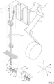
Figure 1 is a schematic view of a packaging machine having at least one capping apparatus, with parts removed for clarity; -
Figure 2 is a schematic view of the capping apparatus ofFigure 1 , with parts removed for clarity; -
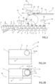
Figures 3A and 3B are schematic top views of a portion of a main body prior (Figure 3A ) and after (Figure 3B ) the application of the opening device onto the main body. - Number 1 indicates as a whole a packaging machine for producing
packages 2 filled with a pourable product, in particular a pourable food product, such as (pasteurized) milk, fruit juice, wine, tomato sauce, salt, sugar, emulsions, yoghurt, milk drinks etc. - Packaging machine 1 may be configured to produce
packages 2 filled with the pourable product. - In more detail, packaging machine 1 may be configured to produce
packages 2 from a packaging material having a multilayer configuration. - In further detail, the packaging material may comprise at least one layer of fibrous material, such as e.g. a paper or cardboard, and at least two layers of heat-seal plastic material, e.g. polyethylene, interposing the layer of fibrous material in between one another. One of these two layers of heat-seal plastic material may define the inner face of
package 2 contacting the pourable product. - Moreover, the packaging material may also comprise a layer of gas- and light-barrier material, e.g. aluminum foil or ethylene vinyl alcohol (EVOH) film, in particular being arranged between one of the layers of the heat-seal plastic material and the layer of fibrous material. Preferentially, the packaging material may also comprise a further layer of heat-seal plastic material being interposed between the layer of gas- and light-barrier material and the layer of fibrous material.
- In further detail, the packaging material may be provided in the form of a web 3.
- With particular reference to
Figures 1 to 3B , eachpackage 2 may comprise a respectivemain body 4 formed from the multilayer packaging material and anopening device 5 applied about a designatedpour opening area 9 of the respectivemain body 4. - In more detail,
main body 4 may extend along a longitudinal axis A, a first transversal axis B perpendicular to longitudinal axis A and a second transversal axis C perpendicular to first transversal axis B and longitudinal axis A. Preferentially, the size ofpackage 2 along longitudinal axis A may be larger than the size ofpackage 2 along first transversal axis B and second transversal axis C. - More specifically,
main body 4 may be parallelepiped-shaped. - According to some preferred non-limiting embodiments,
main body 4 may comprise a first wall, preferentially being transversal, more preferentially perpendicular, to longitudinal axis A, from whichmain body 4 may extend along longitudinal axis A. More specifically, the first wall may define a support surface ofpackage 2, preferentiallymain body 4, which may be designed to be put in contact with a support, such as e.g. a shelf, when, in use, being e.g. exposed within a sales point or when being stored. - The first wall may define a bottom wall of
package 2, in particularmain body 4. - More specifically,
main body 4 may also comprise aside wall 6 being (fixedly) connected to first wall and extending, along longitudinal axis A, from first wall. - More specifically,
main body 4 may also comprise asecond wall 7 opposite to first wall and being (fixedly) connected toside wall 6. - More specifically,
side wall 6 may be interposed between and integrally connected to the first wall andsecond wall 7. - More specifically,
second wall 7 may define a top wall ofpackage 2. - According to the shown non-limiting embodiment, the first wall and
second wall 7 may be parallel with respect to one another. - According to some other possible embodiments not shown,
second wall 7 and the first wall may be inclined with respect to one another, more specificallysecond wall 7 may be inclined with respect to the first wall and/or longitudinal axis A. - According to some non-limiting embodiments,
second wall 7 may carry and/or comprise the designated pouropening area 9 andopening device 5 may be connected tosecond wall 7. - According to some possible embodiments, each designated pour
opening area 9 may be covered by a separation membrane, the separation membrane may e.g. be formed from portions of the multilayer packaging material. E.g. separation membrane may comprise one or more layers of a heat-seal material, and possibly a layer of a gas-barrier material. - In further detail, each
main body 4 may comprise one or moretransversal seals 8. - More specifically, each
second wall 7 may comprise one respectivetransversal seal 8. - Additionally, also each first wall may comprise one respective transversal seal (not visible).
- According to some possible embodiments,
transversal seals 8 may be (substantially) parallel to first transversal axis B. - In further detail, each
transversal seal 8 may (substantially) linearly extend (i.e. eachtransversal seal 8 has a (substantially) linear shape). - According to some possible embodiments, each
main body 4 may also comprise a longitudinal seal. More specifically, each longitudinal seal may be (substantially) perpendicular to the respectivetransversal seals 8. - In further detail, each
opening device 5 may comprise a collar having an outlet opening and acap 10 removably coupled to the collar. Additionally, eachopening device 5 may also comprise arespective base frame 11 carrying the respective collar. More specifically, each collar extends from the respective base frame. - More specifically, each collar may be integral to the
respective base frame 11. - According to some possible embodiments, each
base frame 11 may be connected, e.g. sealed and/or bonded and/or adhesively bonded and/or glued, to the respectivemain body 4, more specifically the respectivesecond wall 7. - In further detail, each
cap 10 may be controllable between a respective closing position at which cap 10 closes the outlet opening (for impeding the outflow of the pourable product) and an opening position at which cap 10 frees the outlet opening (for allowing the outflow of the pourable product). Advantageously, eachcap 10 is in the closing position when being delivered to an end user. - Advantageously, each
cap 10 may be (repeatably) moveable between the respective closing position and the respective opening position. - According to some embodiments, each
cap 10 may be controllable between the respective closing position and the respective opening position by means of a screw movement and/or an angular movement about a hinge axis.Cap 10 may be non-detachably connected tocollar 11 through a tethering element in order to avoid thatcap 10 is dispersed in the environment. - Moreover, each
cap 10 may comprise aprincipal wall 13 configured to cover the outlet opening, in particular withcap 10 being in the closing position. - Advantageously,
principal wall 13 may have a (substantially) circular shape. - Moreover, each
principal wall 13 may have acenter 14. - According to some possible embodiments, each
principal wall 13 may have one or more auxiliary circular elements arranged between an outer edge and therespective center 14. E.g. one or more auxiliary circular elements may be defined by respective circular edges. - Additionally, each
cap 10 may comprise a lateral wall protruding from the respectiveprincipal wall 13 and being configured to surround at least a portion of the respective collar, in particular withcap 10 being in the closing position. - According to some possible embodiments, each
opening device 5 may also comprise a respective coupling element connected to and protruding from the respective separation membrane. Preferentially, each coupling element may be also connected to, preferentially sealed to, therespective cap 10. - In particular, during a first-time control of the
respective cap 10 into the respective opening position, the coupling element follows movement of therespective cap 10 leading to a detachment of the respective separation membrane from the respectivemain body 4. - According to some embodiments, each
opening device 5 may comprise a cutting element configured to cut the separation membrane during a first-time movement ofcap 10 from the respective closing position to the respective opening position. - In further detail, each collar may extend along a respective central axis.
- Moreover, each collar may have an annular shape. More specifically, each collar may have a cylindrical shape.
- With particular reference to
Figure 1 , packaging machine 1 may comprise: - a
package filling apparatus 17 configured to form and fillmain bodies 4, in particular configured to formmain bodies 4 from the multilayer packaging material and to fillmain bodies 4 with the pourable product; and - at least one
capping apparatus 18 configured to at least apply onerespective opening device 5 to eachmain body 4, more specifically at least to the respectivesecond wall 7. - More specifically,
main bodies 4 exiting frompackage filling apparatus 17 may comprise the respective designated pour openingarea 9, possibly being covered by the respective separation membrane. - In more detail, capping
apparatus 18 may be arranged downstream frompackage filling apparatus 17 and may be configured to receive formed and filledmain bodies 4 frompackage filling apparatus 17. - With particular reference to
Figure 1 , cappingapparatus 18 comprises: - a conveying device configured to advance
main bodies 4 along and advancement path P; and - an opening
device application apparatus 19 configured to apply onerespective opening device 5 onto eachmain body 4, more specifically at least the respectivesecond wall 7, even more specifically about the designated pour openingarea 9, at anapplication station 20. - In further detail, the conveying device may comprise elements such as bars or the like configured to define the position of
main bodies 4, in particular such that play into directions transversal to an advancement direction along advancement path P ofmain bodies 4 is (substantially) avoided. - Additionally, opening
device application apparatus 19 may comprise: - one or more opening device applicators configured to apply opening
devices 5 ontomain bodies 4 atapplication station 20; and - preferentially but not necessarily, one or more adjustment devices configured to control a relative position of each opening device applicator with respect to the respective designated pour openings.
- According to some possible non-limiting embodiments, capping
application apparatus 18 may also comprise afeeding device 21 configured to feed openingdevices 5 to atransfer station 22 at which openingdevices 5 are transferred to one respective opening device applicator. - Additionally, feeding
device 21 may be configured to advance openingdevices 5 along a feeding path Q and to transferstation 22. - According to some possible embodiments, capping
apparatus 18 may also comprise anadhesive application device 23 for applying a bonding agent such as an adhesive onto openingdevices 5, preferentially therespective base frame 11 prior to application of openingdevices 5 ontomain body 4. - More specifically,
adhesive application device 23 may be configured to apply the bonding agent and/or adhesive onto openingdevices 5 at agluing application station 24. - E.g. gluing
application station 24 may be upstream fromtransfer station 22 along feeding path Q. - With particular reference to
Figures 1 and2 , cappingapparatus 18 may also comprise aninspection apparatus 30 configured to determine the relative positions of eachopening device 5 with respect to the respective designated pour openingareas 9. - Moreover,
inspection apparatus 30 may be configured to determine on whether eachopening device 5 may be correctly arranged with respect to the respective designated pour openingarea 9. - More specifically,
inspection apparatus 30 may be configured to selectively determine for eachopening device 5 on whether the relative position of eachopening device 5 with respect to the respective designated pour openingarea 9 lies within a desired range or on whether the relative position may fall out of the desired range. - Preferentially but not necessarily,
inspection apparatus 30 may be configured to selectively determine for eachpackage 2 on whether therespective opening device 5 is correctly aligned or misaligned with respect to the respective designated pour openingarea 9 in dependence on whether the respective relative position of eachopening device 5 with respect to the respective designated pour openingarea 9 lies within the desired range (correctly aligned) or on whether the relative position may fall out of the desired range (misaligned). - Even more specifically,
inspection apparatus 30 may be configured to determine on whether the relative position of the respective collar with respect to the respective designated pour openingarea 9 may allow a correct opening of the respective designated pour openingarea 9. - With particular reference to
Figures 2, 3A and 3B ,inspection apparatus 30 comprises: - a
first imaging device 31 positioned at afirst inspection station 32 and configured to acquire a first image 33 (seeFigure 3A ) of animaging portion 34 ofmain body 4, more specifically the respectivesecond wall 7, eachimaging portion 34 having the respective designated pour openingarea 9; and - a
second imaging device 35 positioned at asecond inspection station 36 arranged downstream from first inspection station 32 (along advancement path P) and configured to acquire at least one second image 37 (seeFigure 3B ) of therespective opening device 5 applied to the respectivemain body 4, in particular at therespective inspection portion 34. - Moreover,
second imaging device 35 may be configured to substantially acquire the respective second images 37 (seeFigure 3B ) of substantially therespective imaging portions 34. Whilefirst imaging device 31 is configured to image therespective imaging portions 34 prior to the application of therespective opening devices 5 onto the respectivemain bodies 4,second imaging device 36 is configured to image therespective imaging portions 34 after the application of therespective opening devices 5 onto the respectivemain bodies 4. - In further detail,
first imaging station 32 andsecond imaging station 36 may be arranged, respectively, upstream and downstream fromapplication station 20. - When reverting again to
Figure 2 ,inspection apparatus 30 also comprises an analyzingunit 38 configured to analyze eachfirst image 33 and the respectivesecond image 37 and to determine a relative position between each openingdevice 5 and the respective designated pour openingarea 9 from an assessment of eachfirst image 33 and the respectivesecond image 37. - Advantageously, analyzing
unit 38 may be configured to selectively determine for eachpackage 2 on whether therespective opening device 5 is correctly aligned or misaligned in dependence on whether the relative position of therespective opening device 5 with respect to the respective designated pour openingarea 9 lies, respectively, within a respective certain range or not. - In more detail, analyzing
unit 38 may be configured to determine a measured first relative position of each designated pour openingarea 9 with respect to a first reference station 39 from each respectivefirst image 33. - First reference station 39 being the same for any acquired
first image 33 as being an inherent feature of the position offirst imaging device 31. E.g. first reference station 39 may be attributed to one or more specific pixels offirst image 33, which are the same for anyfirst image 33 taken. - In more detail, each
first image 33 taken, in use, byfirst imaging device 33 has a defined size which is the same for eachfirst image 33. Moreover, therespective inspection portions 34 are visible within the respectivefirst image 33. - Hence, the first reference station 39 is thereby a fixed point within each
first image 33 and which remains the same for eachfirst image 33. E.g. it can be considered that first reference station 39 defines a zero point. - In even further detail, analyzing
unit 38 may be configured to determine the first relative position with reference to a first reference point 40 of each designated pour openingarea 9, such as e.g. a center point of designated pour openingarea 9. - Thus, while first reference station 39 is an inherent feature of any
first image 33, which is independent of the specific visual effects present withinfirst image 33, first reference point 40 corresponds to a specific point of each designated pour openingarea 9. - E.g. when reverting to
Figure 3A , it is possible to define the center of the designated pour openingarea 9 as the first reference point 40 and analyzingunit 38 determines the relative position of the center with respect to first reference station 39. In the ideal case such a relative position would be the same for eachfirst image 33. However, during normal production, deviations may occur for varying reasons. Thus, by having first reference station 39 being an inherent feature related to eachfirst image 33 and being determined by the position offirst imaging device 31 and by determining the relative position of the respective first reference points 40 with respect to such first reference station 39, it is possible to understand the real position of the respective designated pour openingarea 9. - More specifically, analyzing
unit 38 may be configured to determine the relative position of the respective first reference point 40 with respect to the first reference station 39 and such a relative position being indicative about the relative respective first relative position. - In other words, analyzing
unit 38 sets, in use, a fixed first reference station 39 being the same for eachfirst image 33. - Hence, the relative position of each first reference point 40 with respect to first reference station 39 describes a translation between first reference point 40 (e.g. the center of the designated pour opening area 9) and the respective first reference station 39 (e.g. the expected position of the center of the designated pour opening
area 9 in an ideal situation). - In the example shown, first reference station 39 is set by analyzing
unit 38 and for eachfirst image 33 such that in the ideal case the respective centers of the respective designated pour openingareas 9 correspond to first reference station 39. - Even more specifically, analyzing
unit 38 may be configured to attribute to first reference station 39 a first set of cartesian coordinates and to first reference point 40 a second set of cartesian coordinates. Thereby, the first set of cartesian coordinates is the same for eachfirst image 33 and the second set of cartesian coordinates corresponds to the effective measurement. Accordingly, the respective relative position of first reference point 40 with respect to first reference station 39 is expressed in terms of delta values. - E.g. first reference station 39 may define a zero point of the cartesian coordinate system.
- In other words, first reference station 39 allows to define the position of the first reference point 40.
- According to some embodiments, analyzing
unit 38 may be configured to determine a measured second relative position of eachopening device 5 with respect to asecond reference station 41 from the respectivesecond images 37. - In analogy to
first images 33, first reference station 39 andfirst imaging device 31, alsosecond reference station 41 is a station, which is inherently related tosecond imaging device 36 and its specific position. - Accordingly, also
second reference station 41 is the same for eachsecond image 41 and is independent on any visual features present withinsecond images 41. - In more detail, analyzing
unit 38 may be configured to determine the relative position of eachopening device 5 with respect to the respective designated pour openingarea 9 in dependence of the measured first relative position and the measured respective second relative position. - According to some embodiments, analyzing
unit 38 may be configured to determine the second relative position with reference to asecond reference point 44 ofopening device 5, such as therespective center 14. In analogy tofirst images 33, first reference point 40 andfirst imaging device 31, also second reference point 40 is attributable to a feature of the specific visualized features. In this case, however, second reference point 40 corresponds to a point of openingdevice 5. - E.g. in the example shown,
second reference station 41 is defined such that, in the ideal case,second reference point 44 is arranged atsecond reference station 41. However, in use, differences betweensecond reference point 44 andsecond reference station 41 may occur. - Indeed,
second reference point 44 may be translated fromsecond reference station 41. - E.g. it may be possible to define
second reference station 41 such that the respective centers 14 (as the respective second reference point 44) of therespective opening devices 5 correspond tosecond reference station 41 if the position of therespective opening device 5 within the respectivesecond image 37 corresponds to the ideal case. - Even more specifically, analyzing
unit 38 may be configured to attribute to second reference station 41 a third set of cartesian coordinates and to second reference point 44 a fourth set of cartesian coordinates. In particular, the third set of cartesian coordinates is fixed and the same for eachsecond image 37 and the fourth set of cartesian coordinates depends on the effective measurement result. - E.g.
second reference station 44 may define a 0 point of the cartesian coordinate system. - According to some preferred non-limiting embodiments, analyzing
unit 38 may be also configured to calculate an expected relative position of eachopening device 5 from the respective first relative position of the respective designated pour openingarea 9 and to compare the measured second relative position (i.e. as obtained from the respective second image 37) with the expected relative position so as to determine the relative position between the designated pour openingarea 9 and therespective opening device 5. - In other words, in use, analyzing
unit 38 calculates from the respective first relative positions respective expected positions of eachopening device 5 and compares the expected positions with the positions as determined form the respectivesecond images 37. - Moreover, analyzing
unit 38 may be also configured to determine any deviations of the position of openingdevice 5 from the expected relative position (i.e. the difference between the expected relative position and the measured relative position). - Additionally, analyzing
unit 38 may be configured to determine a correctly and incorrectly alignedopening device 5 if the deviations are, respectively, smaller or equal to and larger than a threshold. - In other words, analyzing
unit 38 calculates for each designated pour openingarea 9 the respective first relative position. Then analyzingunit 38 calculates from the first relative position the expected position of therespective opening device 5 and compares the expected position to the effective position. If the effective position stays within a certain limit with respect to the expected position,opening device 5 is considered to be correctly aligned and if the effective position with respect to the expected position is outside from the certain limit,opening device 5 is incorrectly aligned. - According to some preferred non-limiting embodiments, analyzing
unit 38 may be configured to compare the relative position of the respectivesecond reference point 44 with respect to the respectivefirst reference point 41. - More specifically, analyzing
unit 38 may be configured to: - identify in each first image (33) the center of the respective designated pour opening area (9);
- identify in the respective second image (38)
center 14 of therespective opening device 5 applied around the respective designated pour openingarea 9; and - determine a relative position between the respective center of the designated pour opening
area 9 and therespective center 14 of therespective opening device 5. - Moreover, analyzing
unit 38 may be configured to determine if therespective opening device 5 is applied correctly or not by comparing the relative position between the center of the respective designated pour openingarea 9 and therespective center 14 of therespective opening device 5 with a predetermined expected relative position. - In particular, the expected relative position provides that the respective center of the respective designated pour opening
area 9 and therespective center 14 of therespective opening device 5 are superposed or distanced from each other by a predetermined threshold. - According to some preferred non-limiting embodiments,
first imaging device 31 may comprise a 2D camera configured to acquirefirst images 33. - According to some preferred non-limiting embodiments,
second imaging device 35 may comprise a 3D camera, more specifically a digital video camera, more specifically a 3D digital video camera, configured to acquiresecond images 37. More, specifically,first imaging device 35 may be configured to acquire a three-dimensional image. - E.g.
second imaging device 35 may be configured to execute a 3D profiling (laser triangulation). - According to some preferred non-limiting embodiments, adjustment devices may be configured to control the relative position of opening device applicators in dependence of the respective
first images 33, more specifically of the first relative position of the respective designated pouringoutlet 9 as obtained from the respectivefirst images 33. - In this way, it is possible to reduce any misalignments of opening
devices 5. - According to some preferred non-limiting embodiments,
inspection apparatus 30 may also comprise athird imaging device 42 configured to acquire third images of openingdevices 5 together with the bonding agent and/or the adhesive applied to openingdevice 5 at athird imaging station 43. - Third images may be logged.
- According to some possible embodiments, analyzing
unit 38 may be configured to log together the respectivefirst image 33, the respectivesecond image 37 and, preferably, the respective third image of thesame package 2, in order to render them e.g. available for further analysis aimed at understanding the source of possible defective applications of anopening device 5. - More specifically,
third imaging station 43 may be interposed between gluingapplication station 24 andtransfer station 22. - With particular reference to
Figure 1 ,package filling apparatus 17 may be configured to producemain bodies 4 and to fillmain bodies 4 with the pourable product. - In more detail,
package filling apparatus 17 may be configured to producemain bodies 4 by forming atube 50 from web 3, longitudinally sealingtube 50, fillingtube 50 with the pourable product and to form and transversally seal and cuttube 50. - In use, packaging machine 1 produces
packages 2 filled with the pourable product. - Operation of packaging machine 1 comprises at least the steps of:
- forming and filling
main bodies 4 with the pourable product, in particular executed bypackage filling apparatus 17; and - applying
caps 10 ontomain bodies 4, more specifically at least ontosecond walls 7. - Operation of packaging machine 1 also comprises a step of inspecting, during which relative position of opening
devices 5 are determined with respect to the respective designated pour openingarea 9. - Even more particular, during the step of forming and filling,
tube 50 is formed from advancing web 3, is longitudinally sealed, filled with the pourable product and transversally sealed and cut. - According to some preferred embodiments, operation of packaging machine 1 may also comprise a step of feeding, during which
main bodies 4 are fed, in particular frompackage filling apparatus 7, to cappingapparatus 18. - In more detail, during the step of applying, the following sub-steps are executed:
- advancing
main bodies 4 along the advancement path; and - applying
opening devices 5 onto the respectivemain bodies 4. - In more detail, during the sub-step of applying, opening
devices 5 are applied onto the respectivemain bodies 4 by the respective opening device applicators atglue application station 23. - Moreover, during the sub-step of applying, a bonding agent and/or an adhesive is applied onto opening
devices 5. - The method comprises the step of inspecting
opening device 5 so as to selectively determine the relative position between designated pouropenings 9 and therespective opening devices 5. - The method comprises the steps of:
- acquiring, in particular by means of
first imaging device 31, the respectivefirst images 33 atfirst inspection station 32 of therespective imaging portions 34; - acquiring, in particular by means of
second imaging device 35, the respectivesecond images 37 atsecond inspection station 36 of eachimaging portion 34 together with therespective opening devices 4 applied to the respectivemain bodies 4; and - analyzing, in particular by means of analyzing
unit 38, eachfirst image 33 and the respectivesecond image 38 and to determine the respective relative positions between each openingdevice 5 and the respective designated pour openingarea 9 from the analysis of eachfirst image 33 and the respectivesecond image 37. - In more detail, during the step of analyzing, the measured first relative position of each designated pour opening
area 9 with respect to first reference station 39 of the respectivefirst image 33 is determined and a measured second relative position of eachopening device 5 with respect to asecond reference station 41 from the respectivesecond images 37 is determined, too. - Moreover, during the step of analyzing the relative position of each
opening device 5 with respect to the respective designated pour openingarea 9 is determined in dependence of the measured first relative position and the measured respective second relative position. - Additionally, during the step of analyzing, each first relative position is determined with reference to the respective first reference point 40 of the respective designated pour opening
area 9 and the second relative position is determined with reference to the respectivesecond reference point 41. - In further detail, during the step of analyzing, the expected relative positions of each
opening device 5 are calculated from the respective first relative positions of the respective designated pouropenings 9. Then, the respective second relative positions obtained from the respectivesecond image 37 are compared with the respective expected relative positions so as to determine the relative positions between the respective designated pouropenings 5 and therespective opening devices 5. - According to some possible embodiments, during the step of analyzing, each
opening device 5 may be classified as correctly or incorrectly aligned with respect to the respective designated pouropenings 9. - According to some possible embodiments,
packages 2 having incorrectly aligned openingdevices 5 may be discarded. - The advantages of
inspection apparatus 30 and the method according to the present invention will be clear from the foregoing description. - In particular,
inspection apparatus 30 and/or the method of inspection allow to determine with high precision the relative position of eachopening device 5 with respect to the respective designated pour openingarea 9. In such a way, it is possible to identify incorrectly applied openingdevices 5 with greater precision, since the position of theopening device 5 is evaluated with respect to the designated pour openingarea 9. So, if anopening device 5 is not aligned with its respective pour openingarea 9, then it is identified as incorrectly applied. - In particular, it is possible to identify
packages 2 having misaligned openingdevices 5, which allows to avoid that these are delivered to the consumer. - Clearly, changes may be made to
inspection apparatus 30 and/or cappingapparatus 18 and/or packaging machine 1 and/or the method as described herein without, however, departing from the scope of protection as defined in the accompanying claims.
Claims (17)
- - Inspection apparatus (30) for inspecting opening devices (5) applied to main bodies (4) advancing along an advancement path (P);
wherein the inspection apparatus (30) comprises:- a first imaging device (31) positioned at a first inspection station (32) and configured to acquire a first image (33) of an imaging portion (34) of the main body (4), the imaging portion (34) having a designated pour opening area (9) configured to receive a respective opening device (5) ;- a second imaging device (35) positioned at a second inspection station (36) arranged downstream from the first inspection station (32) and configured to acquire at least one second image (37) of the opening device (4) applied to the respective imaging portion (34) of the main body (4); and- an analyzing unit (38) configured to analyze each first image (33) and the respective second image (38) and to determine a relative position between each opening device (5) and the respective designated pour opening area (9) by analyzing each first image (33) and the respective second image (37). - - Inspection apparatus according to claim 1, wherein the analyzing unit (38) is configured to determine a measured first relative position of each designated pour opening area (9) with respect to a first reference station (39) from the respective first image (33), and to determine a measured second relative position of each opening device (5) with respect to a second reference station (41) from the respective second images (37);
wherein the analyzing unit (38) is configured to determine the relative position of each opening device (5) with respect to the respective designated pour opening area (9) in dependence of the measured first relative position and the measured respective second relative position. - - Inspection apparatus according to claim 2, wherein the analyzing unit (38) is configured to determine the measured first relative position with reference to a first reference point (40) of the designated pour opening area (9) and to determine the second measured relative position with reference to a second reference point (44).
- - Inspection apparatus according to claim 3, wherein the first reference point (40) corresponds to a center of the designated pour opening area (9) and/or the second reference point (44) corresponds to a center (14) of the opening device (5).
- - Inspection apparatus according to any one of claims 2 to 4, wherein the analyzing unit (38) is also configured to calculate an expected relative position of each opening device (5) from the respective first relative position of the respective designated pour opening area (9) and to compare the respective second relative position obtained from the respective second image (37) with the expected relative position so as to determine the relative position between the designated pour opening (5) and the opening device (5).
- - Inspection apparatus according to any one of the preceding claims, wherein the first imaging device (31) comprises a 2D camera.
- - Inspection apparatus according to any one of the preceding claims, wherein second imaging device (35) comprises a 3D camera and/or is configured to execute a three-dimensional profiling.
- - Inspection apparatus according to any one of the preceding claims, wherein the inspection apparatus (30) is configured to selectively determine for each opening device (5) on whether the relative position of each opening device (5) with respect to the respective designated pour opening area (9) lies within a desired range or on whether the relative position may fall out of the desired range.
- - Capping apparatus (18) for applying opening devices onto main bodies (4) advancing along an advancement path (P) comprising:- an opening device application apparatus (19) configured to apply respective opening devices (5) onto the main bodies (4) at an application station (20); and- an inspection apparatus (30) according to any one of the preceding claims configured to determine the relative positions of each opening device (5) with respect to the respective designated pour openings (9);wherein the application station (20) is interposed between the first inspection station (32) and the second inspection station (36).
- - Capping apparatus (18) according to claim 9, wherein the opening device application apparatus (19) comprises one or more opening device applicators and one or more adjustment devices configured to adjust a position of each opening device applicator in dependence of respective relative positions of each designated pour opening area (9) as determined from the respective first images (33).
- - Capping apparatus (18) according to claim 9 or 10, wherein the opening device application apparatus (19) also comprises an adhesive application device (23) for applying a bonding agent and/or an adhesive onto the opening devices (5) prior to application of opening devices (5) onto the respective main bodies (4);
wherein the inspection apparatus (30) further comprises a third imaging device (42) configured to acquire at least one respective third image of each opening device (5) and the bonding agent and/or adhesive applied to the respective opening device (5). - - Packaging machine (1) for producing packages (2) having each a main body (4) and an opening device (5) applied onto the main body (4) and being filled with a pourable product comprising:- a package filling apparatus (17) for forming and filling the main bodies (4) with the pourable product; and- at least one capping apparatus (18) according to any one of claims 9 to 11 and being configured to apply respective opening devices (5) onto main bodies (4).
- - Method of inspecting opening devices (5) applied onto main bodies (4) filled with a pourable product comprising the steps of:- acquiring a first image (33) at a first inspection station (32) of an imaging portion (34) of the main body (4), the imaging portion (34) having a designated pour opening area (9) of each main body (4);- acquiring a second image (37) at a second inspection station (36) arranged downstream from the first inspection station (32) of the respective opening device (4) applied to the respective imaging portion (34); and- analyzing each first image (33) and the respective second image (38) and determining a relative position between each opening device (5) and the respective designated pour opening area (9) from the analysis of each first image (33) and the respective second image (37).
- - Method according to claim 13, during the step of analyzing a measured first relative position of each designated pour opening (9) with respect to a first reference station (39) of the respective first image (33) and to determine a measured second relative position of each opening device (5) with respect to a second reference station (41) from the respective second images (37);
wherein during the step of analyzing the relative position of each opening device (5) with respect to the respective designated pour opening (9) is determined in dependence of the measured first relative position and the measured respective second relative position. - - Method according to claim 14, wherein during the step of analyzing the first relative position is determined with reference to a first reference point (40) of the designated pour opening (9) and the second relative position is determined with reference to a second reference point (44) .
- - Method according to any one of claims 13 to 15, wherein during the step of analyzing unit an expected relative position of each opening device (5) is calculated from the respective first relative position of the respective designated pour opening (9) and the respective second relative position obtained from the respective second image (37) is compared with the expected relative position so as to determine the relative position between the designated pour opening (5) and the opening device (5).
- - Method of applying opening devices (5) onto main bodies (4) filled with a pourable product comprising the steps of:- advancing main bodies (4) along an advancement path (P) ;- applying opening devices (5) onto the main bodies (4); and- executing a method according to any one of claims 13 to 16.
Applications Claiming Priority (1)
| Application Number | Priority Date | Filing Date | Title |
|---|---|---|---|
| IT102023000020940A IT202300020940A1 (en) | 2023-10-09 | 2023-10-09 | INSPECTION APPARATUS FOR A CAPPING MACHINE, CAPPING MACHINE HAVING AN INSPECTION APPARATUS, PACKAGING PLANT, METHOD OF INSPECTING CAPS AND METHOD OF CAPPING |
Publications (2)
| Publication Number | Publication Date |
|---|---|
| EP4538219A1 true EP4538219A1 (en) | 2025-04-16 |
| EP4538219B1 EP4538219B1 (en) | 2026-04-08 |
Family
ID=89158537
Family Applications (1)
| Application Number | Title | Priority Date | Filing Date |
|---|---|---|---|
| EP24192286.3A Active EP4538219B1 (en) | 2023-10-09 | 2024-08-01 | Inspection apparatus for a capping apparatus, capping apparatus having an inspection apparatus, packaging machine, method of inspecting caps and method of applying caps |
Country Status (3)
| Country | Link |
|---|---|
| EP (1) | EP4538219B1 (en) |
| IT (1) | IT202300020940A1 (en) |
| WO (1) | WO2025078054A1 (en) |
Citations (3)
| Publication number | Priority date | Publication date | Assignee | Title |
|---|---|---|---|---|
| DE4239238A1 (en) * | 1992-11-21 | 1994-05-26 | Khs Masch & Anlagenbau Ag | Plastics bottle filling station - uses gas under pressure to test bottle for leakage before it is filled with a liq. |
| WO2021229912A1 (en) * | 2020-05-15 | 2021-11-18 | 四国化工機株式会社 | Mouth plug adhering apparatus and mouth plug adhering method |
| US20230086224A1 (en) * | 2020-03-20 | 2023-03-23 | Tetra Laval Holdings & Finance S.A. | Method for controlling a plurality of carts movable along an endless track |
-
2023
- 2023-10-09 IT IT102023000020940A patent/IT202300020940A1/en unknown
-
2024
- 2024-08-01 WO PCT/EP2024/071830 patent/WO2025078054A1/en active Pending
- 2024-08-01 EP EP24192286.3A patent/EP4538219B1/en active Active
Patent Citations (3)
| Publication number | Priority date | Publication date | Assignee | Title |
|---|---|---|---|---|
| DE4239238A1 (en) * | 1992-11-21 | 1994-05-26 | Khs Masch & Anlagenbau Ag | Plastics bottle filling station - uses gas under pressure to test bottle for leakage before it is filled with a liq. |
| US20230086224A1 (en) * | 2020-03-20 | 2023-03-23 | Tetra Laval Holdings & Finance S.A. | Method for controlling a plurality of carts movable along an endless track |
| WO2021229912A1 (en) * | 2020-05-15 | 2021-11-18 | 四国化工機株式会社 | Mouth plug adhering apparatus and mouth plug adhering method |
Also Published As
| Publication number | Publication date |
|---|---|
| EP4538219B1 (en) | 2026-04-08 |
| IT202300020940A1 (en) | 2025-04-09 |
| WO2025078054A1 (en) | 2025-04-17 |
Similar Documents
| Publication | Publication Date | Title |
|---|---|---|
| US5924267A (en) | Process and a device for closing filled folded-carton packages | |
| EP4538219B1 (en) | Inspection apparatus for a capping apparatus, capping apparatus having an inspection apparatus, packaging machine, method of inspecting caps and method of applying caps | |
| US20240158128A1 (en) | Composite packaging material sheet, method for forming a composite packaging material sheet, composite package and method for forming a composite package | |
| JP2025143448A (en) | Inductors and ultrasonic horns | |
| EP4524087A1 (en) | Inspection apparatus for a capping machine, respective capping machine and packaging plant | |
| CN122003380A (en) | Inspection equipment for capping equipment, capping equipment with inspection equipment, packaging machine, method for inspecting caps, and method for applying caps. | |
| EP4524086A1 (en) | Inspection apparatus for a capping machine, respective capping machine and packaging plant | |
| US11597553B2 (en) | Assembly for producing sealed packaging units | |
| US20200108963A1 (en) | A method for providing transversal seals to a tube of packaging material, and a sealing jaw assembly | |
| US11535419B2 (en) | Sheet packaging material for producing sealed packages for pourable food products, sealed package for pourable food products and a method of manufacturing a sealed package for pourable products | |
| EP4596428A1 (en) | Packaging machine for producing sealed packages containing a pourable product, corresponding method and computer program product | |
| EP4556387A1 (en) | Package filled with a pourable product and packaging blank for forming a package | |
| EP4556388A1 (en) | Package filled with a pourable product and packaging blank for forming a package | |
| EP4575472A1 (en) | Inspection system for a capping machine and method for inspecting closure structures pre-applied on packages containing a pourable product | |
| US20260021930A1 (en) | Packaging blank for forming a package and package formed from a packaging blank | |
| US20250388358A1 (en) | Packaging blank for forming a package and package formed from a packaging blank | |
| EP4491524B1 (en) | Cap application device for a capping apparatus, capping apparatus for a packaging machine and packaging machine having a capping apparatus | |
| EP4357256A1 (en) | Package forming apparatus for a packaging machine and packaging machine for forming packages filled with a pourable product | |
| EP4588648A1 (en) | Apparatus and method for applying a sealing strip of a heat-sealable material to a web of packaging material, packaging machine for forming sealed packages | |
| WO2024200345A1 (en) | Capping apparatus for a packaging machine and packaging machine having a capping apparatus | |
| CN121219199A (en) | Capping equipment for capping devices, capping devices for packaging machines, and packaging machines equipped with capping devices. | |
| JP2017019544A (en) | Ultrasonic wave seal method and device |
Legal Events
| Date | Code | Title | Description |
|---|---|---|---|
| PUAI | Public reference made under article 153(3) epc to a published international application that has entered the european phase |
Free format text: ORIGINAL CODE: 0009012 |
|
| STAA | Information on the status of an ep patent application or granted ep patent |
Free format text: STATUS: THE APPLICATION HAS BEEN PUBLISHED |
|
| AK | Designated contracting states |
Kind code of ref document: A1 Designated state(s): AL AT BE BG CH CY CZ DE DK EE ES FI FR GB GR HR HU IE IS IT LI LT LU LV MC ME MK MT NL NO PL PT RO RS SE SI SK SM TR |
|
| STAA | Information on the status of an ep patent application or granted ep patent |
Free format text: STATUS: REQUEST FOR EXAMINATION WAS MADE |
|
| 17P | Request for examination filed |
Effective date: 20251016 |
|
| GRAP | Despatch of communication of intention to grant a patent |
Free format text: ORIGINAL CODE: EPIDOSNIGR1 |
|
| STAA | Information on the status of an ep patent application or granted ep patent |
Free format text: STATUS: GRANT OF PATENT IS INTENDED |
|
| GRAS | Grant fee paid |
Free format text: ORIGINAL CODE: EPIDOSNIGR3 |
|
| GRAA | (expected) grant |
Free format text: ORIGINAL CODE: 0009210 |
|
| STAA | Information on the status of an ep patent application or granted ep patent |
Free format text: STATUS: THE PATENT HAS BEEN GRANTED |
|
| INTG | Intention to grant announced |
Effective date: 20260210 |
|
| AK | Designated contracting states |
Kind code of ref document: B1 Designated state(s): AL AT BE BG CH CY CZ DE DK EE ES FI FR GB GR HR HU IE IS IT LI LT LU LV MC ME MK MT NL NO PL PT RO RS SE SI SK SM TR |
|
| REG | Reference to a national code |
Ref country code: CH Ref legal event code: F10 Free format text: ST27 STATUS EVENT CODE: U-0-0-F10-F00 (AS PROVIDED BY THE NATIONAL OFFICE) Effective date: 20260408 Ref country code: GB Ref legal event code: FG4D |
|
| REG | Reference to a national code |
Ref country code: DE Ref legal event code: R096 Ref document number: 602024003798 Country of ref document: DE |