EP4538175A1 - Tray table with electronic device positioning apparatus - Google Patents
Tray table with electronic device positioning apparatus Download PDFInfo
- Publication number
- EP4538175A1 EP4538175A1 EP23202974.4A EP23202974A EP4538175A1 EP 4538175 A1 EP4538175 A1 EP 4538175A1 EP 23202974 A EP23202974 A EP 23202974A EP 4538175 A1 EP4538175 A1 EP 4538175A1
- Authority
- EP
- European Patent Office
- Prior art keywords
- tray table
- main body
- electronic device
- tray
- stowed
- Prior art date
- Legal status (The legal status is an assumption and is not a legal conclusion. Google has not performed a legal analysis and makes no representation as to the accuracy of the status listed.)
- Pending
Links
Images


Classifications
-
- B—PERFORMING OPERATIONS; TRANSPORTING
- B64—AIRCRAFT; AVIATION; COSMONAUTICS
- B64D—EQUIPMENT FOR FITTING IN OR TO AIRCRAFT; FLIGHT SUITS; PARACHUTES; ARRANGEMENT OR MOUNTING OF POWER PLANTS OR PROPULSION TRANSMISSIONS IN AIRCRAFT
- B64D11/00—Passenger or crew accommodation; Flight-deck installations not otherwise provided for
- B64D11/06—Arrangements of seats, or adaptations or details specially adapted for aircraft seats
- B64D11/0638—Arrangements of seats, or adaptations or details specially adapted for aircraft seats with foldable tables, trays or cup holders
-
- B—PERFORMING OPERATIONS; TRANSPORTING
- B60—VEHICLES IN GENERAL
- B60N—SEATS SPECIALLY ADAPTED FOR VEHICLES; VEHICLE PASSENGER ACCOMMODATION NOT OTHERWISE PROVIDED FOR
- B60N3/00—Arrangements or adaptations of other passenger fittings, not otherwise provided for
- B60N3/001—Arrangements or adaptations of other passenger fittings, not otherwise provided for of tables or trays
- B60N3/002—Arrangements or adaptations of other passenger fittings, not otherwise provided for of tables or trays of trays
- B60N3/004—Arrangements or adaptations of other passenger fittings, not otherwise provided for of tables or trays of trays of foldable trays mounted on the back-rest
-
- B—PERFORMING OPERATIONS; TRANSPORTING
- B64—AIRCRAFT; AVIATION; COSMONAUTICS
- B64D—EQUIPMENT FOR FITTING IN OR TO AIRCRAFT; FLIGHT SUITS; PARACHUTES; ARRANGEMENT OR MOUNTING OF POWER PLANTS OR PROPULSION TRANSMISSIONS IN AIRCRAFT
- B64D11/00—Passenger or crew accommodation; Flight-deck installations not otherwise provided for
- B64D11/0015—Arrangements for entertainment or communications, e.g. radio, television
- B64D11/00152—Seat back fixtures for removable monitors, e.g. tablet computers
Definitions
- the present disclosure relates generally to a tray table (e.g.) for an aircraft passenger seat comprising an apparatus for positioning an electronic device.
- Airline passengers have evolved to carry more personal electronic devices, such as smart phones and tablet, and provide their own in flight entertainment via such personal electronic devices.
- the airline industry hasn't adapted to giving passengers a better inflight experience by providing a dedicated somewhere for passengers to put their devices to view emails, movies, etc., during a flight.
- Traditional passenger tray tables don't allow for good ergonomics to watch a film unless passengers bring their own device supports.
- a tray table for a passenger seat, the tray table having a main body defining a table surface.
- the tray table comprises a first member configured to slide relative to the main body between a first position and a second, extended position.
- the first member at least when in the second, extended position is configured to define a first rest for supporting a first portion of an electronic device.
- the tray table also comprises a second member configured to move relative to the main body between a first, stowed position and a second, extended position. In the second position the second member protrudes upwardly from the table surface of the main body to define a second rest for supporting a second portion of an electronic device.
- the first member and the second member when in their respective second, extended positions, thus cooperate to support and position an electronic device.
- the tray table provides simple and effective means for positioning an electronic device, e.g., and in particular, such that a screen of the device can be angled towards the passenger's eye-line at a desired viewing angle, without requiring the passenger to hold the electronic device.
- the tray table also allows the first and second members to be moved to stowed positions, so that the tray table provides the dual purpose of a (normal) table surface and an electronic device support.
- the tray table may be a tray table that is designed for a passenger seat of an aircraft.
- the arrangement described above is particularly suited for this context, because the first and second members can be stowed away relative to the tray table when not in use, such that the tray table can be effectively stowed during aircraft take-off or landing, e.g. in the normal manner for an aircraft tray table.
- the tray table could find utility in other situations, in particular for other passenger vehicles, such as on-board a train.
- the first member may be configured to support a bottom of an electronic device (with the 'bottom' being defined based on the screen orientation) whereas the second member is configured to support a back of the electronic device, with the electronic device thus being supported at these two points (and in embodiments only at these two points).
- the first and second members may be operable and configured to move relative to the tray table in any suitable and desired manner, e.g. so long as they can move between a respective stowed position and a respective extended position in which they can provide the electronic device support.
- first member In the first position the first member is in a stowed position and in the second position the first member is in a deployed position. Similarly, in the first position the second member is in a stowed position and in the second position the first member is in a deployed position.
- the second member may be configured to only be retained in the first or second position. That is, the second member may be moveable only between two discrete positions. This provides simplicity in terms of deployment of the second member by the passenger, and the second position may be selected such that it is suitable for supporting a back of different types of electronic devices.
- the second member and the first member may be configured to be moved manually between the first and second positions.
- the second member may be angled relative to the table surface when the second member is in the second position.
- the angle may be, for example, non-perpendicular, for example the second member may be configured to be angled towards the electronic device when in the second position, in order to provide a robust support for the electronic device.
- the second member may be a flap, wherein a bottom end of the flap is pivotally attached to the main body and the flap is configured such that an upper edge of the flap contacts and supports a back of an electronic device in order to position the electronic device.
- the first member may comprise two rods, and the end portion may be a beam joining the rods.
- the two rods are configured to be received in a or the cavity of the main body. In use, the two rods can slide into and out of the cavity in order to move the first member between the first and second positions.
- the beam may by used to support a bottom of the electronic device.
- the first member may be operable to extend from the first position to multiple extended positions (one of which may be the second position) in order to support and position the electronic device at different angles. In the different extended positions, the first member is more or less extended out of (or spaced from) the main body. This affects the position of a bottom of the device relative to the second member, which affects the angle of the device. This allows the position of the electronic device to be adjusted depending on the passenger's needs. For example, a taller passenger may wish to have a more shallow angle of the electronic device such that a screen of the electronic device is close to perpendicular to the eyeline of the passenger.
- the second member may be operable to slide continuously between a stowed position and a fully extended position in order to support and position the electronic device at a range of different angles. This provides even more flexibility in terms of positions of the electronic device.
- the first member may be moved and retained to and between any position between the stowed (or first position) and fully extended position.
- An extended position is defined as any position of the first member in which the first member is deployed from the stowed position, i.e. in which the first member has been slid out from the main body. In any extended position an end of the first member may be is spaced from the main body (by a greater or lesser extend).
- the fully extended position may be a position in which an or the end portion of the first member is at its furthest possible position from the main body.
- the end portion may be a portion of the first member which is furthest from the main body.
- the first member may comprise two rods and a beam joining the rods, where the two rods are configured to be received the cavity.
- This provides a low-weight but robust arrangement for the first member, and the beam can be used to support a bottom of the electronic device.
- the cavity may comprise two cavities, each caviting being configured to receive a respective rod.
- the first member may comprise a stop configured to abut against a stop in the cavity of the main body when the first member reaches a or the fully extended position.
- the stop may be a flange provided on an internal end of the first member.
- the first member may be configured to slide into or out of a or the cavity which is formed in an end of the tray table closest to the passenger in use. This allows the electronic device to be positioned in a convenient and appropriate position for the user to view a screen of the electronic device, without (for example) taking up space laterally. This is particularly important in contexts where there is less space, for example on an aircraft or bus.
- the main body may comprise a bushing disposed in a or the cavity, the first member being in sliding contact with the bushing.
- the bushing provides stability to the first member and allows the first member to slide effectively relative to the main body.
- a bushing is also relatively inexpensive and easy to assembly.
- a material of the bushing may be selected such that the bushing provides sufficient friction to the first member that the first member stays in a particular position, but not so much friction that the first member cannot be manually moved between positions by the passenger.
- the second member may be hinged to the table surface of the main body. Where provided, the hinge may be provided in the pocket formed in the table surface. The second member may be hinged to a central portion of the table surface of the main body.
- an apparatus comprising an aircraft passenger seat and a tray table according to any of the above, wherein the tray table is attached to the aircraft seat and is moveable between a stowed and deployed position relative to the aircraft seat, wherein the tray table is configured to operate as described above when the tray table is in the deployed position.
- the tray table is particularly well suited to an aircraft passenger seat, because the parts forming the tray table are simple to produce and are relatively lightweight compared with other modes of support.
- the first and second members of the tray table can be easily stowed (and will stay in their stowed positions) when the tray table is stowed during aircraft take-off or landing.
- a tray table according to any of the above onto a passenger aircraft seat, the method comprising providing at least two arms of the tray table, and pivotally attaching the tray table to the aircraft via the at least two arms.
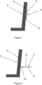
- the tray table 4 further comprises two arms 10, where one end of each arm 10 is pivotally attached to the back 6 of the seat 2, and the opposite end of each arm 10 is pivotally attached to the main body 8 of the tray table 4.
- the arms 10 facilitate movement of the tray table 4 between the stowed and deployed positions.
- the rotatable member 14 is pivotally attached to the main body 8 and is configured to rotate between a stowed position (not shown) and a folded position (as illustrated in Figure 3 ). In the stowed position, the rotatable member 14 is received in a pocket (not shown) in the upper table surface 12 of the main body 8 such that the rotatable member 14 is flush with the upper table surface 12. As shown in Figure 3 , when the rotatable member 14 is in a deployed position, the rotatable member 14 is angled relative to the upper table surface 12.
- the rotatable member 14 illustrated is in the form of a flap, which is generally flat and has a rectangular profile. However, other shapes for the rotatable member 14 are envisaged.
- the slidable member 16 is configured to slide relative to the main body 8 between a stowed position (not shown) and an extended position, as illustrated in Figure 3 .
- the slidable member 16 comprises two rods 17 and and end portion 19 in the form of a beam 19 connecting the ends of the rods 17.
- the rods 17 are elongate members which each extend into a respective bore 21 in the main body 8 of the tray table 4. In use, the rods 17 slide into our out of the bores 21 in order to move the beam 19 closer to or further away from the main body 8.
- the rods 17 are able to slide continuously within the bores 21 between a stowed position, in which the beam 19 contacts the main body 8, and a fully extended position, in which the beam 19 is at a maximum distance from the main body 8.
- Figure 5 illustrates a side view of the tray table 4 and electronic device 23 shown in Figure 4 , but with the slidable member 16 in a less extended position to that shown in Figure 4 , such that the beam 19 is closer to (albeit not in contact with, i.e. not yet fully stowed) the main body 8.
- the angle between the back 27 of the electronic device 23 and the top table surface 12 of the main body 8 is larger than the positioning shown in Figure 4 .
- Figures 4 to 6 serve to illustrate that the position of the slidable member 16 can be adjusted to achieve different angles of the electronic device 23 relative to the main body 8 of the tray table 4. This can improve the user experience, because the user can choose an angle of the electrical device which is most comfortable to them (for example, depending on the height of the user).
- Figure 7 illustrates a cross-sectional side view of the main body 8 of the tray table 4.
- the main body 4 comprises a pocket 18 for receiving the rotatable member when the rotatable member is in the stowed position.
- the pocket 18 is sized to complement the shape of the rotatable member such that the rotatable member can be fully received in the pocket 18 and flush with the top table surface 12 of the main body 8.
- a side surface 20 of the pocket 18 adjacent to the pivot axis of the rotatable member is angled greater than 90 degrees relative to a bottom surface 31 of the pocket 18. As shown in Figure 8 , this side surface 20 can act to contact and support the rotatable member when the rotatable member is in the deployed position.
- Figure 8 illustrates a cross sectional side view of the main body 4 shown in Figure 7 and an embodiment of a rotatable member 14, which is shown in a deployed position.
- the axis of rotation 22 of the rotatable member 14 extends through an end portion 32 of the rotatable member 14.
- the end portion 32 is radiused, which helps to allow the rotatable member 14 to rotate between the stowed and deployed position within the pocket 18.
- the angled side surface 20 of the pocket 18 is in contact with a surface of the rotatable member 14 such that the rotatable member 14 extends along and at the same angle as the angled surface 20.
- the rotatable member 14 is angled towards the slidable member 16 when in the deployed position. Angling the rotatable member 14 towards the slidable member 16 means that an angle between the rotatable member 14 and the electronic device being supported can be closer to 90 degrees than if the rotatable member 14 were at a right angle relative to the top table surface 12, for example. The result of this is that the rotatable member 14 can more easily stay in its deployed position without inadvertently moving to the stowed position.
- Figure 9 illustrates a cross sectional side view of the main body 8 shown in Figure 7 , and another embodiment of a rotatable member 114 (shown in a deployed position).
- This rotatable member 114 differs from that shown in Figure 8 in that the axis of rotation 122 of the rotatable member 114 is provided adjacent to a corner of the rotatable member 114. This placement of the axis of rotation 122 allows space for the rotatable member 114 to rotate between the stowed and deployed position without the need for a radiused end portion of the rotatable member 114.
- Figure 10 illustrates a cross-sectional side view of an embodiment of a main body 8 and slidable member 16, the cross section taken along one of the rods 17 of the slidable member 16.
- the slidable member 16 is shown in a depoloyed position, with the beam 19 positioned between the stowed and fully extended position.
- the main body 8 includes a respective cavity 33 for each rod 17 of the slidable member 16.
- the main body 8 includes a bushing 24 within the illustrated cavity 33. The bushing 24 surrounds and is in sliding contact with the rod 17.
- the materials of the rod 17 and the bushing 24 are selected to provide sufficient friction that the sliding member 16 stays in a particular position during use, but not so much friction that the user cannot easily manually move the slidable member 16 between different positions.
- a stop 28 At an internal end of the rod 17 there is provided a stop 28 which provides a flange 34. The flange 34 contacts the bushing 24 when the slidable member 16 is in the fully extended position, thereby preventing further extension of the slidable member 16.
- Figure 11 illustrates a cross-sectional side view of another embodiment of a main body 108 and slidable member 116.
- This embodiment is similar to the embodiment illustrated in Figure 10 , except that in this embodiment there are air vents 130 provided in the bottom of the main body 108 to allow air to enter or exit the cavity 133 containing the rod 117. This helps to provide smooth movement of the slidable member 116.
- Figure 12 illustrates a schematic illustration of an embodiment of a rotatable member 214 and a strut 234 for propping up the rotatable member 214.
- the strut 234 is pivotally attached to the main body of the tray table, and can be lifted by a user and placed under the rotatable member 214 in order to retain the rotatable member 214 in the deployed position.
- the strut 234 comprises a hollow cylinder which includes a spring 235 and a ball bearing 236 attached to an end of the spring 235.
- the rotatable member 214 has an indentation 237 which receives the ball bearing 236 when the strut 234 is placed under the rotatable member 214 in the deployed position.
- the ball bearing 236 will be pushed into the hollow cylinder of the strut 234 (against the force of the spring), and the strut 234 will fall into a stowed position (folded into the pocket of the main body). This prevents the rotatable member 214 or the strut 234 from breaking in use.
- Figure 14 shows a schematic illustration of another embodiment of a rotatable member 414 and a portion of the main body 408.
- a surface 440 of the pocket 418 of the main body 408 provides a protruding feature 442, and an adjacent portion of the rotatable member 414 provides a corresponding groove 444.
- the protruding feature 442 will snap into the corresponding groove 444 in order to retain the rotatable member 414 in the deployed position.
- Figure 15 shows a schematic illustration of another embodiment of a rotatable member 514 and a portion of the main body 508.
- a surface 540 of the pocket 518 provides a protruding feature 546 and an adjacent portion of the rotatable member also provides a protruding feature 548.
- the protruding feature 548 of the rotatable member 514 becomes wedged with the protruding feature 546 of the main body 508 in order to retain the rotatable member 514 in the deployed position.
- tray trable has been described above with reference to various embodiments, it will be understood by those skilled in the art that various changes in form and detail may be made without departing from the scope of the invention as set forth in the accompanying claims.
Landscapes
- Engineering & Computer Science (AREA)
- Aviation & Aerospace Engineering (AREA)
- Transportation (AREA)
- Mechanical Engineering (AREA)
- Vehicle Step Arrangements And Article Storage (AREA)
Abstract
Description
- The present disclosure relates generally to a tray table (e.g.) for an aircraft passenger seat comprising an apparatus for positioning an electronic device.
- Airline passengers have evolved to carry more personal electronic devices, such as smart phones and tablet, and provide their own in flight entertainment via such personal electronic devices. The airline industry hasn't adapted to giving passengers a better inflight experience by providing a dedicated somewhere for passengers to put their devices to view emails, movies, etc., during a flight. Traditional passenger tray tables don't allow for good ergonomics to watch a film unless passengers bring their own device supports.
- It is therefore desired to provide improved means for supporting and positioning a passenger's personal electronic device during a flight.
- According to a first aspect there is provided a tray table for a passenger seat, the tray table having a main body defining a table surface. The tray table comprises a first member configured to slide relative to the main body between a first position and a second, extended position. The first member at least when in the second, extended position is configured to define a first rest for supporting a first portion of an electronic device. The tray table also comprises a second member configured to move relative to the main body between a first, stowed position and a second, extended position. In the second position the second member protrudes upwardly from the table surface of the main body to define a second rest for supporting a second portion of an electronic device. The first member and the second member, when in their respective second, extended positions, thus cooperate to support and position an electronic device.
- The tray table provides simple and effective means for positioning an electronic device, e.g., and in particular, such that a screen of the device can be angled towards the passenger's eye-line at a desired viewing angle, without requiring the passenger to hold the electronic device. The tray table also allows the first and second members to be moved to stowed positions, so that the tray table provides the dual purpose of a (normal) table surface and an electronic device support.
- The tray table may be a tray table that is designed for a passenger seat of an aircraft. The arrangement described above is particularly suited for this context, because the first and second members can be stowed away relative to the tray table when not in use, such that the tray table can be effectively stowed during aircraft take-off or landing, e.g. in the normal manner for an aircraft tray table. However, in principle, the tray table could find utility in other situations, in particular for other passenger vehicles, such as on-board a train.
- For example, and in a typical use case, the first member may be configured to support a bottom of an electronic device (with the 'bottom' being defined based on the screen orientation) whereas the second member is configured to support a back of the electronic device, with the electronic device thus being supported at these two points (and in embodiments only at these two points).
- Subject to the particular requirements of the present disclosure, the first and second members may be operable and configured to move relative to the tray table in any suitable and desired manner, e.g. so long as they can move between a respective stowed position and a respective extended position in which they can provide the electronic device support.
- For example, the second member may be configured to pivot or rotate relative to the table surface between the first and second positions, whereas (as mentioned above) the first member is designed to slide relative to the main body. The first member may thus be referred to as a "slidable member" and the second member may be referred to as a "rotatable member". Other arrangements would however be possible.
- In the first position the first member is in a stowed position and in the second position the first member is in a deployed position. Similarly, in the first position the second member is in a stowed position and in the second position the first member is in a deployed position.
- The second member may be configured to only be retained in the first or second position. That is, the second member may be moveable only between two discrete positions. This provides simplicity in terms of deployment of the second member by the passenger, and the second position may be selected such that it is suitable for supporting a back of different types of electronic devices.
- The second member and the first member may be configured to be moved manually between the first and second positions.
- The main body may comprise a pocket configured to receive the second member in the first position such that the second member is substantially flush with the table surface when the second member is in the first position. The result of this is a flat table surface when the second member is in the first position, such that the table surface can be used to rest objects (for example food or drink) on it when the second member is stowed away in the first position.
- The second member may be angled relative to the table surface when the second member is in the second position. The angle may be, for example, non-perpendicular, for example the second member may be configured to be angled towards the electronic device when in the second position, in order to provide a robust support for the electronic device.
- The second member may be a flap, wherein a bottom end of the flap is pivotally attached to the main body and the flap is configured such that an upper edge of the flap contacts and supports a back of an electronic device in order to position the electronic device.
- The first member may comprise an end portion comprising a flange for supporting a bottom of an electronic device. This provides extra supported for the bottom of the electronic device and ensures that the electronic device remains in position when supported by the first and second members.
- The first position of the first member may be a stowed position in which an end portion of the first member is substantially flush with an end portion of the tray table, the stowed position being the position in which the first member is stored in a respective cavity of the main body. The end portion of the first member may be the portion which is furthest from the main body when the first member is in the extended position. When the first member is in the stowed position, the tray table is generally shaped as a conventional tray table which can be used to rest objects on.
- The first member may comprise an or the end portion, and when the first member is in the first position the end portion is in contact with the main body and when the first member is in the second position the end portion is spaced from the main body. The end portion may be the portion of the first member furthest from the main body.
- The second position of the first member may be a deployed position, the deployed position being a position in which the first member can be used to support an electronic device.
- The first member may comprise two rods, and the end portion may be a beam joining the rods. The two rods are configured to be received in a or the cavity of the main body. In use, the two rods can slide into and out of the cavity in order to move the first member between the first and second positions. The beam may by used to support a bottom of the electronic device.
- The first member may be operable to extend from the first position to multiple extended positions (one of which may be the second position) in order to support and position the electronic device at different angles. In the different extended positions, the first member is more or less extended out of (or spaced from) the main body. This affects the position of a bottom of the device relative to the second member, which affects the angle of the device. This allows the position of the electronic device to be adjusted depending on the passenger's needs. For example, a taller passenger may wish to have a more shallow angle of the electronic device such that a screen of the electronic device is close to perpendicular to the eyeline of the passenger. In an embodiment, the second member may be operable to slide continuously between a stowed position and a fully extended position in order to support and position the electronic device at a range of different angles. This provides even more flexibility in terms of positions of the electronic device. The first member may be moved and retained to and between any position between the stowed (or first position) and fully extended position. An extended position is defined as any position of the first member in which the first member is deployed from the stowed position, i.e. in which the first member has been slid out from the main body. In any extended position an end of the first member may be is spaced from the main body (by a greater or lesser extend).
- The fully extended position may be a position in which an or the end portion of the first member is at its furthest possible position from the main body. The end portion may be a portion of the first member which is furthest from the main body.
- The main body may comprise a cavity configured to receive a portion of the first member.
- The first member may comprise two rods and a beam joining the rods, where the two rods are configured to be received the cavity. This provides a low-weight but robust arrangement for the first member, and the beam can be used to support a bottom of the electronic device. In such an arrangement, the cavity may comprise two cavities, each caviting being configured to receive a respective rod.
- The first member may comprise a stop configured to abut against a stop in the cavity of the main body when the first member reaches a or the fully extended position. In embodiments, the stop may be a flange provided on an internal end of the first member.
- The first member may be configured to slide into or out of a or the cavity which is formed in an end of the tray table closest to the passenger in use. This allows the electronic device to be positioned in a convenient and appropriate position for the user to view a screen of the electronic device, without (for example) taking up space laterally. This is particularly important in contexts where there is less space, for example on an aircraft or bus.
- The main body may comprise a bushing disposed in a or the cavity, the first member being in sliding contact with the bushing. The bushing provides stability to the first member and allows the first member to slide effectively relative to the main body. A bushing is also relatively inexpensive and easy to assembly. A material of the bushing may be selected such that the bushing provides sufficient friction to the first member that the first member stays in a particular position, but not so much friction that the first member cannot be manually moved between positions by the passenger.
- The second member may be hinged to the table surface of the main body. Where provided, the hinge may be provided in the pocket formed in the table surface. The second member may be hinged to a central portion of the table surface of the main body.
- The tray table may further comprise a charging port for charging an electronic device, the charging port being provided in the main body of the tray table. The charging port may be connected, for example, to an electrical distribution system of the aircraft using any suitable wiring arrangement. Various arrangements would be possible in this regard.
- There is also provided an apparatus comprising an aircraft passenger seat and a tray table according to any of the above, wherein the tray table is attached to the aircraft seat and is moveable between a stowed and deployed position relative to the aircraft seat, wherein the tray table is configured to operate as described above when the tray table is in the deployed position. The tray table is particularly well suited to an aircraft passenger seat, because the parts forming the tray table are simple to produce and are relatively lightweight compared with other modes of support. Furthermore, the first and second members of the tray table can be easily stowed (and will stay in their stowed positions) when the tray table is stowed during aircraft take-off or landing.
- There is also provided a method of installing a tray table according to any of the above onto a passenger aircraft seat, the method comprising providing at least two arms of the tray table, and pivotally attaching the tray table to the aircraft via the at least two arms.
- Various embodiments will now be described, by way of example only, and with reference to the accompanying drawings in which:
-
Figure 1 shows a schematic side view of a passenger seat of an aircraft with a tray table in a stowed position; -
Figure 2 shows a schematic side view of a passenger seat of an aircraft with a tray table in a depoloyed position; -
Figure 3 shows a diagonal perspective view of an embodiment of the tray table shown inFigures 1 and 2 ; -
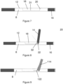
Figure 4 shows a side view of the the tray table ofFigure 3 and an electronic device being supported by the tray table; -
Figure 5 shows a side view of the tray table and electronic device shown inFigure 4 , but with the slidable member in a less extended position to that shown inFigure 4 ; -
Figure 6 shows a side view of the tray table and electronic device shown inFigures 4 and5 , but with the slidable member in a fully extended position; -
Figure 7 shows a cross-sectional side view of the main body of the tray table illustrated inFigures 1 to 6 ; -
Figure 8 illustrates a cross sectional side view of the main body shown inFigure 7 and an embodiment of a rotatable member, which is shown in a deployed position; -
Figure 9 illustrates a cross sectional side view of the main body shown inFigure 7 , and another embodiment of a rotatable member, which is shown in a deployed position; -
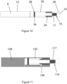
Figure 10 illustrates a cross-sectional side view of an embodiment of a main body and a slidable member, the cross section taken along one of the rods of the slidable member; -
Figure 11 illustrates a cross-sectional side view of another embodiment of a main body and slidable member; -
Figure 12 illustrates a schematic illustration of an embodiment of a rotatable member and a strut for propping up the rotatable member; -
Figure 13 shows a schemamic illustration of another embodiment of a rotatable member and a portion of the pocket of the main body; -
Figure 14 shows a schematic illustration of another embodiment of a rotatable member and a portion of the main body; and -
Figure 15 shows a schematic illustration of yet another embodiment of a rotatable member and a portion of the main body. -
Figures 1 and 2 illustrate a schematic cross-sectional side view of anaircraft passenger seat 2 and a tray table 4.Figure 1 illustrates the tray table 4 in a stowed position, andFigure 2 illustrates the tray table 4 in a deployed position. In the stowed position, the tray table 4 is folded up so that it is held against a back 6 of theseat 2. The tray table 4 may be retained in the stowed position using a rotatable clip (not shown). The tray table 4 comprises amain body 8 which provides anupper table surface 12. When the tray table 4 is deployed, theupper table surface 12 is generally horizontal and can be used by a passenger in a seat behind the one illustrated to rest objects on (for example food and drink). The tray table 4 further comprises twoarms 10, where one end of eacharm 10 is pivotally attached to theback 6 of theseat 2, and the opposite end of eacharm 10 is pivotally attached to themain body 8 of the tray table 4. Thearms 10 facilitate movement of the tray table 4 between the stowed and deployed positions. -
Figure 3 illustrates a diagonal perspective view of an embodiment of the tray table 4 shown inFigures 1 and 2 . The tray table 4 comprises arotatable member 14 configured to rotate relative to themain body 8, and aslidable member 16 configured to slide relative to themain body 8. As explained in more detail below, therotatable member 14 and theslidable member 16 cooperate to provide a support for an electronic device (for example a smart phone or tablet). The tray table 4 further comprises a chargingport 18 for charging an electronic device. - The
rotatable member 14 is pivotally attached to themain body 8 and is configured to rotate between a stowed position (not shown) and a folded position (as illustrated inFigure 3 ). In the stowed position, therotatable member 14 is received in a pocket (not shown) in theupper table surface 12 of themain body 8 such that therotatable member 14 is flush with theupper table surface 12. As shown inFigure 3 , when therotatable member 14 is in a deployed position, therotatable member 14 is angled relative to theupper table surface 12. Therotatable member 14 illustrated is in the form of a flap, which is generally flat and has a rectangular profile. However, other shapes for therotatable member 14 are envisaged. - The
slidable member 16 is configured to slide relative to themain body 8 between a stowed position (not shown) and an extended position, as illustrated inFigure 3 . Theslidable member 16 comprises tworods 17 and and endportion 19 in the form of abeam 19 connecting the ends of therods 17. Therods 17 are elongate members which each extend into arespective bore 21 in themain body 8 of the tray table 4. In use, therods 17 slide into our out of thebores 21 in order to move thebeam 19 closer to or further away from themain body 8. Therods 17 are able to slide continuously within thebores 21 between a stowed position, in which thebeam 19 contacts themain body 8, and a fully extended position, in which thebeam 19 is at a maximum distance from themain body 8. -
Figure 4 illustrates a side view of the the tray table 4 ofFigure 3 and anelectronic device 23 being supported by the tray table 4. As illustrated, a top 25 of the rotatable member supports a back 27 of theelectronic device 23, and thebeam 19 supports a bottom 29 of theelectronic device 23. Thebeam 19 provides alip 30 on which the bottom 29 of theelectronic device 23 rests. This helps to prevent theelectronic device 23 from slipping relative to theslidable member 16. In the illustrated example, thebeam 19 of theslidable member 16 is positioned about halfway between the stowed position and the fully extended position. -
Figure 5 illustrates a side view of the tray table 4 andelectronic device 23 shown inFigure 4 , but with theslidable member 16 in a less extended position to that shown inFigure 4 , such that thebeam 19 is closer to (albeit not in contact with, i.e. not yet fully stowed) themain body 8. As can be seen, the angle between the back 27 of theelectronic device 23 and thetop table surface 12 of themain body 8 is larger than the positioning shown inFigure 4 . -
Figure 6 illustrates a side view of the tray table 4 andelectronic device 23 shown inFigures 4 and5 , but with theslidable member 16 in a fully extended position. As shown, the angle between the back 27 of theelectronic device 23 and thetop table surface 12 of themain body 8 is smaller than the positions shown inFigures 4 and5 . -
Figures 4 to 6 serve to illustrate that the position of theslidable member 16 can be adjusted to achieve different angles of theelectronic device 23 relative to themain body 8 of the tray table 4. This can improve the user experience, because the user can choose an angle of the electrical device which is most comfortable to them (for example, depending on the height of the user). -
Figure 7 illustrates a cross-sectional side view of themain body 8 of the tray table 4. As mentioned above, themain body 4 comprises apocket 18 for receiving the rotatable member when the rotatable member is in the stowed position. Thepocket 18 is sized to complement the shape of the rotatable member such that the rotatable member can be fully received in thepocket 18 and flush with thetop table surface 12 of themain body 8. As illustrated, aside surface 20 of thepocket 18 adjacent to the pivot axis of the rotatable member is angled greater than 90 degrees relative to abottom surface 31 of thepocket 18. As shown inFigure 8 , thisside surface 20 can act to contact and support the rotatable member when the rotatable member is in the deployed position. -
Figure 8 illustrates a cross sectional side view of themain body 4 shown inFigure 7 and an embodiment of arotatable member 14, which is shown in a deployed position. In this embodiment, the axis ofrotation 22 of therotatable member 14 extends through anend portion 32 of therotatable member 14. In the illustrated embodiment, theend portion 32 is radiused, which helps to allow therotatable member 14 to rotate between the stowed and deployed position within thepocket 18. As illustrated, when therotatable member 14 is in the deployed position, theangled side surface 20 of thepocket 18 is in contact with a surface of therotatable member 14 such that therotatable member 14 extends along and at the same angle as theangled surface 20. This means that therotatable member 14 is angled towards theslidable member 16 when in the deployed position. Angling therotatable member 14 towards theslidable member 16 means that an angle between therotatable member 14 and the electronic device being supported can be closer to 90 degrees than if therotatable member 14 were at a right angle relative to thetop table surface 12, for example. The result of this is that therotatable member 14 can more easily stay in its deployed position without inadvertently moving to the stowed position. -
Figure 9 illustrates a cross sectional side view of themain body 8 shown inFigure 7 , and another embodiment of a rotatable member 114 (shown in a deployed position). Thisrotatable member 114 differs from that shown inFigure 8 in that the axis ofrotation 122 of therotatable member 114 is provided adjacent to a corner of therotatable member 114. This placement of the axis ofrotation 122 allows space for therotatable member 114 to rotate between the stowed and deployed position without the need for a radiused end portion of therotatable member 114. -
Figure 10 illustrates a cross-sectional side view of an embodiment of amain body 8 andslidable member 16, the cross section taken along one of therods 17 of theslidable member 16. Theslidable member 16 is shown in a depoloyed position, with thebeam 19 positioned between the stowed and fully extended position. As explained above, themain body 8 includes arespective cavity 33 for eachrod 17 of theslidable member 16. Themain body 8 includes abushing 24 within the illustratedcavity 33. Thebushing 24 surrounds and is in sliding contact with therod 17. The materials of therod 17 and thebushing 24 are selected to provide sufficient friction that the slidingmember 16 stays in a particular position during use, but not so much friction that the user cannot easily manually move theslidable member 16 between different positions. At an internal end of therod 17 there is provided astop 28 which provides aflange 34. Theflange 34 contacts thebushing 24 when theslidable member 16 is in the fully extended position, thereby preventing further extension of theslidable member 16. -
Figure 11 illustrates a cross-sectional side view of another embodiment of amain body 108 andslidable member 116. This embodiment is similar to the embodiment illustrated inFigure 10 , except that in this embodiment there areair vents 130 provided in the bottom of themain body 108 to allow air to enter or exit thecavity 133 containing therod 117. This helps to provide smooth movement of theslidable member 116. -
Figure 12 illustrates a schematic illustration of an embodiment of arotatable member 214 and astrut 234 for propping up therotatable member 214. Thestrut 234 is pivotally attached to the main body of the tray table, and can be lifted by a user and placed under therotatable member 214 in order to retain therotatable member 214 in the deployed position. Thestrut 234 comprises a hollow cylinder which includes aspring 235 and aball bearing 236 attached to an end of thespring 235. Therotatable member 214 has anindentation 237 which receives theball bearing 236 when thestrut 234 is placed under therotatable member 214 in the deployed position. If excessive force is applied to therotatable member 214, theball bearing 236 will be pushed into the hollow cylinder of the strut 234 (against the force of the spring), and thestrut 234 will fall into a stowed position (folded into the pocket of the main body). This prevents therotatable member 214 or thestrut 234 from breaking in use. -
Figure 13 shows a schemamic illustration of another embodiment of arotatable member 314 and a portion of thepocket 318 of the main body. As shown, therotatable member 314 provides acam follower 338 attached to abottom surface 339 of therotatable member 314, and a portion of thebottom surface 331 of thepocket 318 provides a cam surface. As therotatable member 314 rotates from the stowed position towards the deployed position, thecam follower 338 on therotatable member 314 will become wedged against thecammed surface 331. This acts to retain therotatable member 314 in the deployed position. In order to move therotatable member 314 from the deployed position to the stowed position, the user can push therotatable member 314 towards its stowed position, where the force applied by the user can overcome the friction between thecam follower 338 and thecam surface 331 thereby freeing therotatable member 314 from its deployed position. -
Figure 14 shows a schematic illustration of another embodiment of arotatable member 414 and a portion of themain body 408. In this embodiment, asurface 440 of thepocket 418 of themain body 408 provides aprotruding feature 442, and an adjacent portion of therotatable member 414 provides acorresponding groove 444. When therotatable member 414 reaches the deployed position, the protrudingfeature 442 will snap into thecorresponding groove 444 in order to retain therotatable member 414 in the deployed position. -
Figure 15 shows a schematic illustration of another embodiment of arotatable member 514 and a portion of themain body 508. In this embodiment, asurface 540 of thepocket 518 provides aprotruding feature 546 and an adjacent portion of the rotatable member also provides aprotruding feature 548. When therotatable member 514 reaches the deployed position, the protrudingfeature 548 of therotatable member 514 becomes wedged with theprotruding feature 546 of themain body 508 in order to retain therotatable member 514 in the deployed position. - Although as tray trable has been described above with reference to various embodiments, it will be understood by those skilled in the art that various changes in form and detail may be made without departing from the scope of the invention as set forth in the accompanying claims.
Claims (13)
- A tray table for a passenger seat, the tray table having a main body defining a table surface, and the tray table comprising:a first member configured to slide relative to the main body between a first position and a second, extended position, wherein at least when in the second, extended position the first member is configured to define a first rest for supporting a first portion of an electronic device; anda second member configured to move relative to the main body between a first, stowed position and a second, extended position, wherein in the second position the second member protrudes upwardly from the table surface of the main body to define a second rest for supporting a second portion of an electronic device,wherein the first member and the second member, when in their respective second, extended positions, thus cooperate to support and position an electronic device.
- The tray table of claim 1, wherein the main body comprises a pocket configured to receive the second member in the first position such that the second member is substantially flush with the table surface when the second member is in the first position.
- The tray table of claim 1 or 2, wherein the second member is angled relative to the table surface when the second member is in the second position.
- The tray table of any preceding claim, wherein the first member comprises an end portion comprising a flange for supporting a bottom of an electronic device.
- The tray table of any preceding claim, wherein the first position of the first member is a stowed position in which an end portion of the first member is substantially flush with an end portion of the tray table, the stowed position being the position in which the first member is stored in a respective cavity of the main body.
- The tray table of claim 5, wherein the first member comprises a stop configured to abut against a stop in the cavity of the main body when the first member reaches a or the fully extended positon.
- The tray table of any preceding claim, wherein the first member is operable to extend to multiple different positions in order to support and position the electronic device at different angles.
- The tray table of any preceding claim, wherein the first member is configured to slide into or out of a or the cavity which is formed in an end of the tray table closest to the passenger in use.
- The tray table of any preceding claim, wherein the main body comprises a bushing disposed in a or the cavity, the first member being in sliding contact with the bushing.
- The tray table of any preceding claim, wherein the second member is hinged to the table surface of the main body.
- The tray table of any preceding claim, further comprising a charging port for charging an electronic device, the charging port being provided in the main body of the tray table.
- An apparatus comprising:an aircraft passenger seat; andthe tray table of any preceding claim, wherein the tray table is attached to the aircraft seat and is moveable between a stowed and deployed position relative to the aircraft seat, wherein the tray table is configured to operate as described above when the tray table is in the deployed position.
- A method of installing the tray table of any preceding claim onto a passenger aircraft seat, the method comprising providing at least two arms of the tray table, and pivotally attaching the tray table to the aircraft via the at least two arms.
Priority Applications (2)
| Application Number | Priority Date | Filing Date | Title |
|---|---|---|---|
| EP23202974.4A EP4538175A1 (en) | 2023-10-11 | 2023-10-11 | Tray table with electronic device positioning apparatus |
| US18/892,138 US20250121939A1 (en) | 2023-10-11 | 2024-09-20 | Tray table with electronic device positioning apparatus |
Applications Claiming Priority (1)
| Application Number | Priority Date | Filing Date | Title |
|---|---|---|---|
| EP23202974.4A EP4538175A1 (en) | 2023-10-11 | 2023-10-11 | Tray table with electronic device positioning apparatus |
Publications (1)
| Publication Number | Publication Date |
|---|---|
| EP4538175A1 true EP4538175A1 (en) | 2025-04-16 |
Family
ID=88372236
Family Applications (1)
| Application Number | Title | Priority Date | Filing Date |
|---|---|---|---|
| EP23202974.4A Pending EP4538175A1 (en) | 2023-10-11 | 2023-10-11 | Tray table with electronic device positioning apparatus |
Country Status (2)
| Country | Link |
|---|---|
| US (1) | US20250121939A1 (en) |
| EP (1) | EP4538175A1 (en) |
Citations (6)
| Publication number | Priority date | Publication date | Assignee | Title |
|---|---|---|---|---|
| US5443018A (en) * | 1993-11-15 | 1995-08-22 | Cromwell; Carl E. | Folding tray for attachment to a vehicle seat back |
| US20070283855A1 (en) * | 2006-03-27 | 2007-12-13 | Alexander Pozzi | Tray tables principally for use in passenger vehicles |
| EP2981464A1 (en) * | 2013-04-05 | 2016-02-10 | Singapore Technologies Aerospace Ltd | A support structure for attachment to a tray table for a passenger seat, tray table for a passenger seat, and passenger seat |
| DE102017201455A1 (en) * | 2017-01-30 | 2018-08-02 | Volkswagen Aktiengesellschaft | Vehicle seat for a motor vehicle |
| US20190061953A1 (en) * | 2017-08-31 | 2019-02-28 | Rockwell Collins, Inc. | Tray Table with Personal Entertainment Device Holder |
| WO2020039237A1 (en) * | 2018-08-24 | 2020-02-27 | Safran Seats Usa Llc | Secondary personal item support |
Family Cites Families (19)
| Publication number | Priority date | Publication date | Assignee | Title |
|---|---|---|---|---|
| US6308641B1 (en) * | 1999-05-10 | 2001-10-30 | Brian F. Kingbury | Stowable reading tray |
| US9403596B2 (en) * | 2011-10-13 | 2016-08-02 | SmartTray International, LLC | Tray table with rotatable inner tray and adjustable retention assembly |
| US8826830B2 (en) * | 2011-10-13 | 2014-09-09 | Nick Pajic | Tray table with rotatable inner tray for electronic device docking |
| US9919802B2 (en) * | 2014-04-07 | 2018-03-20 | B/E Aerospace, Inc. | Laterally-expanding tray table |
| CN109414112B (en) * | 2016-04-04 | 2021-10-19 | B/E航空公司 | Tray table that can be unfolded from the lower seat back area |
| US10232946B2 (en) * | 2017-03-30 | 2019-03-19 | B/E Aerospace, Inc. | Aircraft tray table drawer |
| US10919426B1 (en) * | 2017-06-26 | 2021-02-16 | Jordan Campagnone | Console mountable tray for a motor vehicle |
| GB201713813D0 (en) * | 2017-08-29 | 2017-10-11 | Zodiac Seats Uk Ltd | Deployable table assembly |
| US10285495B1 (en) * | 2017-09-06 | 2019-05-14 | Ronald Joseph Valme | Portable desk tray table |
| US11780587B2 (en) * | 2018-02-08 | 2023-10-10 | Haeco Cabin Solutions, Llc | Food tray for passenger seat |
| US11305876B2 (en) * | 2018-07-10 | 2022-04-19 | Rockwell Collins, Inc. | Aircraft cabin apparatus including personal electronic device holder |
| US12280873B2 (en) * | 2019-06-27 | 2025-04-22 | Safran Seats Usa Llc | Portable electronic device holder for seat |
| US11091267B1 (en) * | 2019-11-19 | 2021-08-17 | B/E Aerospace, Inc. | Actuatable tray assembly for an aircraft passenger compartment |
| US11529896B2 (en) * | 2021-03-11 | 2022-12-20 | Faurecia Automotive Seating, Llc | Seat back and adjustable platform assembly |
| GB2606551B (en) * | 2021-05-12 | 2023-09-06 | Safran Seats Gb Ltd | Seat with tray table |
| US12017589B2 (en) * | 2021-07-20 | 2024-06-25 | Faurecia Interior Systems, Inc. | Vehicle interior assembly with foldable device holder |
| US11865959B2 (en) * | 2021-12-09 | 2024-01-09 | Safran Seats Usa Llc | Foldable PED holder |
| CN119898277A (en) * | 2023-10-27 | 2025-04-29 | 通用汽车环球科技运作有限责任公司 | Glove box |
| US20260028123A1 (en) * | 2024-07-24 | 2026-01-29 | B/E Aerospace, Inc. | Aircraft seatback tray table module |
-
2023
- 2023-10-11 EP EP23202974.4A patent/EP4538175A1/en active Pending
-
2024
- 2024-09-20 US US18/892,138 patent/US20250121939A1/en active Pending
Patent Citations (7)
| Publication number | Priority date | Publication date | Assignee | Title |
|---|---|---|---|---|
| US5443018A (en) * | 1993-11-15 | 1995-08-22 | Cromwell; Carl E. | Folding tray for attachment to a vehicle seat back |
| US20070283855A1 (en) * | 2006-03-27 | 2007-12-13 | Alexander Pozzi | Tray tables principally for use in passenger vehicles |
| EP2981464A1 (en) * | 2013-04-05 | 2016-02-10 | Singapore Technologies Aerospace Ltd | A support structure for attachment to a tray table for a passenger seat, tray table for a passenger seat, and passenger seat |
| EP2981464B1 (en) * | 2013-04-05 | 2017-06-07 | Singapore Technologies Aerospace Ltd | A support structure for attachment to a tray table for a passenger seat, tray table for a passenger seat, and passenger seat |
| DE102017201455A1 (en) * | 2017-01-30 | 2018-08-02 | Volkswagen Aktiengesellschaft | Vehicle seat for a motor vehicle |
| US20190061953A1 (en) * | 2017-08-31 | 2019-02-28 | Rockwell Collins, Inc. | Tray Table with Personal Entertainment Device Holder |
| WO2020039237A1 (en) * | 2018-08-24 | 2020-02-27 | Safran Seats Usa Llc | Secondary personal item support |
Also Published As
| Publication number | Publication date |
|---|---|
| US20250121939A1 (en) | 2025-04-17 |
Similar Documents
| Publication | Publication Date | Title |
|---|---|---|
| EP2828162B1 (en) | Deployable table assembly | |
| EP2981464B1 (en) | A support structure for attachment to a tray table for a passenger seat, tray table for a passenger seat, and passenger seat | |
| EP3552968B1 (en) | Mechanism to achieve expandable tray table | |
| US9820568B2 (en) | Integral tray table personal electronic device holder and tray table | |
| EP3450318B1 (en) | Deployable table assembly | |
| EP2799338B1 (en) | Configurable tray table | |
| US10875652B2 (en) | Passenger tray table | |
| US11299276B2 (en) | Seat system with stowable tray | |
| EP3313691B1 (en) | Mounting arm assembly | |
| US10273009B2 (en) | Tray table with personal entertainment device holder | |
| US12280873B2 (en) | Portable electronic device holder for seat | |
| US10744921B2 (en) | Portable electronic device holder for tray tables | |
| US10597159B2 (en) | Portable electronic device holder | |
| WO2017147620A1 (en) | Tray table with adjustable media support surface | |
| EP4538175A1 (en) | Tray table with electronic device positioning apparatus | |
| EP1636087A1 (en) | A stowable table for a vehicle | |
| EP4263351B1 (en) | Aircraft seat design with mountable food tray | |
| US12134472B2 (en) | System including stowable tablet holder apparatus | |
| US12172581B2 (en) | Deployable personal entertainment device holder | |
| EP4353595A1 (en) | Console mounted tray table with helical pivot | |
| EP4488562B1 (en) | Portable electronic device holder with socket and rotating partial-cylinder | |
| EP4438477A1 (en) | Passenger seat with self-stowing portable electronic device holder | |
| EP4335746A1 (en) | System including stowable cupholder apparatus |
Legal Events
| Date | Code | Title | Description |
|---|---|---|---|
| PUAI | Public reference made under article 153(3) epc to a published international application that has entered the european phase |
Free format text: ORIGINAL CODE: 0009012 |
|
| STAA | Information on the status of an ep patent application or granted ep patent |
Free format text: STATUS: THE APPLICATION HAS BEEN PUBLISHED |
|
| AK | Designated contracting states |
Kind code of ref document: A1 Designated state(s): AL AT BE BG CH CY CZ DE DK EE ES FI FR GB GR HR HU IE IS IT LI LT LU LV MC ME MK MT NL NO PL PT RO RS SE SI SK SM TR |
|
| STAA | Information on the status of an ep patent application or granted ep patent |
Free format text: STATUS: REQUEST FOR EXAMINATION WAS MADE |
|
| 17P | Request for examination filed |
Effective date: 20251014 |
|
| STAA | Information on the status of an ep patent application or granted ep patent |
Free format text: STATUS: EXAMINATION IS IN PROGRESS |
|
| 17Q | First examination report despatched |
Effective date: 20260112 |