EP4538170A1 - Additively manufactured aerospace panels and methods - Google Patents
Additively manufactured aerospace panels and methods Download PDFInfo
- Publication number
- EP4538170A1 EP4538170A1 EP24205220.7A EP24205220A EP4538170A1 EP 4538170 A1 EP4538170 A1 EP 4538170A1 EP 24205220 A EP24205220 A EP 24205220A EP 4538170 A1 EP4538170 A1 EP 4538170A1
- Authority
- EP
- European Patent Office
- Prior art keywords
- skin
- lattice
- panel
- examples
- grid
- Prior art date
- Legal status (The legal status is an assumption and is not a legal conclusion. Google has not performed a legal analysis and makes no representation as to the accuracy of the status listed.)
- Pending
Links
Images








Classifications
-
- B—PERFORMING OPERATIONS; TRANSPORTING
- B64—AIRCRAFT; AVIATION; COSMONAUTICS
- B64G—COSMONAUTICS; VEHICLES OR EQUIPMENT THEREFOR
- B64G1/00—Cosmonautic vehicles
- B64G1/22—Parts of, or equipment specially adapted for fitting in or to, cosmonautic vehicles
-
- B—PERFORMING OPERATIONS; TRANSPORTING
- B33—ADDITIVE MANUFACTURING TECHNOLOGY
- B33Y—ADDITIVE MANUFACTURING, i.e. MANUFACTURING OF THREE-DIMENSIONAL [3D] OBJECTS BY ADDITIVE DEPOSITION, ADDITIVE AGGLOMERATION OR ADDITIVE LAYERING, e.g. BY 3D PRINTING, STEREOLITHOGRAPHY OR SELECTIVE LASER SINTERING
- B33Y10/00—Processes of additive manufacturing
-
- B—PERFORMING OPERATIONS; TRANSPORTING
- B33—ADDITIVE MANUFACTURING TECHNOLOGY
- B33Y—ADDITIVE MANUFACTURING, i.e. MANUFACTURING OF THREE-DIMENSIONAL [3D] OBJECTS BY ADDITIVE DEPOSITION, ADDITIVE AGGLOMERATION OR ADDITIVE LAYERING, e.g. BY 3D PRINTING, STEREOLITHOGRAPHY OR SELECTIVE LASER SINTERING
- B33Y80/00—Products made by additive manufacturing
-
- B—PERFORMING OPERATIONS; TRANSPORTING
- B64—AIRCRAFT; AVIATION; COSMONAUTICS
- B64C—AEROPLANES; HELICOPTERS
- B64C1/00—Fuselages; Constructional features common to fuselages, wings, stabilising surfaces or the like
- B64C1/06—Frames; Stringers; Longerons ; Fuselage sections
- B64C1/12—Construction or attachment of skin panels
-
- B—PERFORMING OPERATIONS; TRANSPORTING
- B64—AIRCRAFT; AVIATION; COSMONAUTICS
- B64C—AEROPLANES; HELICOPTERS
- B64C3/00—Wings
- B64C3/26—Construction, shape, or attachment of separate skins, e.g. panels
-
- E—FIXED CONSTRUCTIONS
- E04—BUILDING
- E04B—GENERAL BUILDING CONSTRUCTIONS; WALLS, e.g. PARTITIONS; ROOFS; FLOORS; CEILINGS; INSULATION OR OTHER PROTECTION OF BUILDINGS
- E04B1/00—Constructions in general; Structures which are not restricted either to walls, e.g. partitions, or floors or ceilings or roofs
- E04B1/18—Structures comprising elongated load-supporting parts, e.g. columns, girders, skeletons
- E04B1/19—Three-dimensional [3D] framework structures
-
- B—PERFORMING OPERATIONS; TRANSPORTING
- B22—CASTING; POWDER METALLURGY
- B22F—WORKING METALLIC POWDER; MANUFACTURE OF ARTICLES FROM METALLIC POWDER; MAKING METALLIC POWDER; APPARATUS OR DEVICES SPECIALLY ADAPTED FOR METALLIC POWDER
- B22F10/00—Additive manufacturing of workpieces or articles from metallic powder
- B22F10/20—Direct sintering or melting
- B22F10/28—Powder bed fusion, e.g. selective laser melting [SLM] or electron beam melting [EBM]
-
- B—PERFORMING OPERATIONS; TRANSPORTING
- B22—CASTING; POWDER METALLURGY
- B22F—WORKING METALLIC POWDER; MANUFACTURE OF ARTICLES FROM METALLIC POWDER; MAKING METALLIC POWDER; APPARATUS OR DEVICES SPECIALLY ADAPTED FOR METALLIC POWDER
- B22F3/00—Manufacture of workpieces or articles from metallic powder characterised by the manner of compacting or sintering; Apparatus specially adapted therefor ; Presses and furnaces
- B22F3/10—Sintering only
- B22F3/11—Making porous workpieces or articles
- B22F3/1103—Making porous workpieces or articles with particular physical characteristics
- B22F3/1115—Making porous workpieces or articles with particular physical characteristics comprising complex forms, e.g. honeycombs
-
- B—PERFORMING OPERATIONS; TRANSPORTING
- B29—WORKING OF PLASTICS; WORKING OF SUBSTANCES IN A PLASTIC STATE IN GENERAL
- B29C—SHAPING OR JOINING OF PLASTICS; SHAPING OF MATERIAL IN A PLASTIC STATE, NOT OTHERWISE PROVIDED FOR; AFTER-TREATMENT OF THE SHAPED PRODUCTS, e.g. REPAIRING
- B29C64/00—Additive manufacturing, i.e. manufacturing of three-dimensional [3D] objects by additive deposition, additive agglomeration or additive layering, e.g. by 3D printing, stereolithography or selective laser sintering
- B29C64/10—Processes of additive manufacturing
- B29C64/141—Processes of additive manufacturing using only solid materials
- B29C64/153—Processes of additive manufacturing using only solid materials using layers of powder being selectively joined, e.g. by selective laser sintering or melting
-
- B—PERFORMING OPERATIONS; TRANSPORTING
- B64—AIRCRAFT; AVIATION; COSMONAUTICS
- B64G—COSMONAUTICS; VEHICLES OR EQUIPMENT THEREFOR
- B64G1/00—Cosmonautic vehicles
- B64G1/22—Parts of, or equipment specially adapted for fitting in or to, cosmonautic vehicles
- B64G1/52—Protection, safety or emergency devices; Survival aids
- B64G1/54—Protection against radiation
-
- B—PERFORMING OPERATIONS; TRANSPORTING
- B64—AIRCRAFT; AVIATION; COSMONAUTICS
- B64G—COSMONAUTICS; VEHICLES OR EQUIPMENT THEREFOR
- B64G1/00—Cosmonautic vehicles
- B64G1/22—Parts of, or equipment specially adapted for fitting in or to, cosmonautic vehicles
- B64G1/52—Protection, safety or emergency devices; Survival aids
- B64G1/56—Protection against meteoroids or space debris
-
- B—PERFORMING OPERATIONS; TRANSPORTING
- B64—AIRCRAFT; AVIATION; COSMONAUTICS
- B64G—COSMONAUTICS; VEHICLES OR EQUIPMENT THEREFOR
- B64G1/00—Cosmonautic vehicles
- B64G1/22—Parts of, or equipment specially adapted for fitting in or to, cosmonautic vehicles
- B64G1/52—Protection, safety or emergency devices; Survival aids
- B64G1/58—Thermal protection, e.g. heat shields
-
- Y—GENERAL TAGGING OF NEW TECHNOLOGICAL DEVELOPMENTS; GENERAL TAGGING OF CROSS-SECTIONAL TECHNOLOGIES SPANNING OVER SEVERAL SECTIONS OF THE IPC; TECHNICAL SUBJECTS COVERED BY FORMER USPC CROSS-REFERENCE ART COLLECTIONS [XRACs] AND DIGESTS
- Y10—TECHNICAL SUBJECTS COVERED BY FORMER USPC
- Y10T—TECHNICAL SUBJECTS COVERED BY FORMER US CLASSIFICATION
- Y10T428/00—Stock material or miscellaneous articles
- Y10T428/24—Structurally defined web or sheet [e.g., overall dimension, etc.]
- Y10T428/24149—Honeycomb-like
-
- Y—GENERAL TAGGING OF NEW TECHNOLOGICAL DEVELOPMENTS; GENERAL TAGGING OF CROSS-SECTIONAL TECHNOLOGIES SPANNING OVER SEVERAL SECTIONS OF THE IPC; TECHNICAL SUBJECTS COVERED BY FORMER USPC CROSS-REFERENCE ART COLLECTIONS [XRACs] AND DIGESTS
- Y10—TECHNICAL SUBJECTS COVERED BY FORMER USPC
- Y10T—TECHNICAL SUBJECTS COVERED BY FORMER US CLASSIFICATION
- Y10T428/00—Stock material or miscellaneous articles
- Y10T428/24—Structurally defined web or sheet [e.g., overall dimension, etc.]
- Y10T428/24273—Structurally defined web or sheet [e.g., overall dimension, etc.] including aperture
- Y10T428/24322—Composite web or sheet
Definitions
- the present disclosure relates generally to aerospace structures and, more particularly, to additively manufactured aerospace panels and methods for additively manufacturing aerospace panels.
- the raw material is in the form of granules or powder, applied as a layer, and then selectively fused by a heat source.
- a heat source such as a laser or scanning electron beam.
- Exemplary methods include selective laser melting (SLM), direct metal laser sintering (DMLS), selective laser sintering (SLS), fused deposition modelling (FDM), and electron beam melting (EBM), among others.
- an aerospace panel Disclosed are examples of an aerospace panel, an aerospace vehicle, and examples of systems, apparatuses, and methods relating to additively manufactured aerospace panels.
- the following is a non-exhaustive list of examples, which may or may not be claimed, of the subject matter according to the present disclosure.
- the first skin has a first grid of stiffeners
- the second skin has a second grid of stiffeners
- each truss member extends between a first node, defined at an intersection of the first grid of stiffeners, and a second node, defined at an intersection of the second grid of stiffeners.
- the lattice grid includes one or more grids of lattice stiffeners.
- At least one of the first grid of skin stiffeners and the second grid of skin stiffeners is non-planar.
- the plurality of truss members forms an array of core structures.
- the density of the core structures varies over at least one region of the aerospace panel.
- the disclosed aerospace panel includes a third skin spaced apart from the second skin and a second truss structure connecting the second skin to the third skin.
- the first skin, the second skin, the third skin, the first truss structure, and the second truss structure collectively form the single monolithic joint-free structure.
- At least one of the first skin and the second skin has an internal channel embedded respectively in the first skin and/or the second skin.
- the disclosed aerospace vehicle includes a body having one or more aerospace panels.
- Each one of the aerospace panels includes a first skin, a second skin spaced apart from the first skin, and a first truss structure connecting the first skin to the second skin.
- the first truss structure includes a plurality of truss members. Each one of the truss members is integral with the first skin and the second skin, such that the first skin, the second skin, and the first truss structure collectively form a single monolithic joint-free structure.
- At least one of the first skin and the second skin includes at least one lattice region defining a lattice configured to eliminate secondary printing support.
- the at least one lattice region includes a grid of lattice stiffeners and an array of openings.
- the disclosed method for manufacturing an aerospace panel includes steps of printing a first skin and a second skin spaced apart from the first skin, while simultaneously printing a plurality of truss members of a first truss structure connecting the first skin to the second skin, thereby resulting in a single monolithic joint-free structure.
- At least one of the first skin and the second skin includes at least one lattice region defining a lattice configured to eliminate secondary printing support.
- the at least one lattice region includes a lattice grid and an array of openings.
- the disclosed method includes a step of printing a third skin spaced apart from the second skin and a step of printing a second truss structure connecting the second skin to the third skin, while printing the first skin, the second skin, and the first truss structure.
- the step of printing the first skin and the second skin includes a step of printing at least one of the first skin and the second skin with an internal channel embedded in the first skin and/or the second skin.
- an additively manufactured aerospace panel in accordance with the present teachings includes two skins connected by a truss structure.
- the panel is a single additively manufactured unit.
- the panel may also be described as a sandwich structure, sandwich panel, or sandwich-structured composite material, having two face sheets connected by one or more core structures.
- aerospace vehicle 102 includes a body 104.
- Body 104 generally serves as the primary structure of aerospace vehicle 102.
- Body 104 includes one or more additively manufactured truss panels, including panel 100 ( Figs. 1B-1D ).
- Panel 100 may be used for interior or exterior structures of aerospace vehicle 102, and/or may be used for secondary structures, detachable modules, equipment housings, and/or any appropriate structure of aerospace vehicle 102.
- panel 100 may include features configured for the challenges of the space environment.
- first skin 110 and second skin 112 also includes at least one skin region 126.
- Skin region 126 includes or takes the form of solid, sheet structure made of continuous material that has no holes or openings.
- both first skin 110 and second skin 112 include at least one lattice region 120 and at least one skin region 126.
- Panel 100 is an example of an additively manufactured truss panel.
- Panel 100 includes first skin 110 and second skin 112.
- First skin 110 and second skin 112 are connected by truss structure 114.
- at least one of first skin 110 and/or second skin 112 has at least one region defining a lattice, referred to herein as lattice region 120.
- lattice region 120 includes a lattice grid, referred to herein as lattice 128.
- first skin 110 and/or second skin 112 can have any number of skin regions 126, skin regions 126 can be disposed at any suitable location along the extend of first skin 110 and/or second skin 112, and skin regions 126 can have any suitable size and/or two-dimensional geometry.
- lattice region 120 and skin region 126 share a boundary and extend from and/or between one another to form the extent of first skin 110 and/or second skin 112.
- first skin 110 and second skin 112 includes or is formed of lattice region 120 and skin region 126.
- first skin 110 includes a boundary portion formed by skin region 126 and the remaining interior portion of second skin 112 is formed by lattice region 120.
- skin regions 126 are located along and form the perimeter edges of first skin 110 and surround lattice region 120.
- each truss member 118 of truss structure 114 is coupled to or integrated with first skin 110 or second skin 112 at skin node 134 of skin region 126.
- each one of lattice nodes 130 of first skin 110 is generally aligned with one of skin nodes 134 of second skin 112 along an axis that passes perpendicularly through first skin 110 and second skin 112.
- each truss member 118 extends between lattice node 130 of first skin 110 and skin node 134 of second skin 112. In one or more examples, each truss member 118 extends diagonally between lattice node 130 of first skin 110 and skin node 134 of second skin 112.
- each one of lattice nodes 130 of first skin 110 is generally aligned with one of lattice nodes 130 of second skin 112 along an axis that passes perpendicularly through first skin 110 and second skin 112.
- each truss member 118 extends between lattice node 130 of first skin 110 and lattice node 130 of second skin 112. In one or more examples, each truss member 118 extends diagonally between lattice node 130 of first skin 110 and lattice node 130 of second skin 112.
- Panel 200 is an example of an additively manufactured truss panel, as described herein above and referred to as panel 100.
- Panel 200 includes first skin 210 and second skin 212.
- First skin 210 and second skin 212 are connected by truss structure 214.
- First skin 210 is an example of first skin 110 (e.g., Figs. 1B-5 ).
- Second skin 212 is an example of second skin 112 (e.g., Figs. 1B-5 ).
- Truss structure 214 is an example of truss structure 114 (e.g., Figs. 1B-5 ).
- first skin 210 and/or second skin 212 collectively has at least one lattice region 250.
- Lattice region 250 is an example of lattice region 120 (e.g., Figs. 1B-5 .)
- lattice region 250 includes lattice 251.
- Lattice 251 is an example of lattice 128 (e.g., Figs. 2-5 ).
- Lattice 251 includes a grid of lattice members 254 and array of openings 252.
- Lattice members 254 are examples of lattice members 122 and openings 252 are examples of openings 124 (e.g., Figs. 2-5 ).
- each of first skin 210, second skin 212, and truss structure 214 are shaped, featured, and/or configured according to desired properties of panel 200.
- Panel 200 may be configured for use in any aerospace vehicle. In one or more examples, panel 200 is configured for spacecraft. Panel 200 may function as a structural component, as part of a thermal management system, as radiation shielding, and/or as micrometeoroid and orbital debris (MMOD) shielding for spacecraft, for example.
- MMOD micrometeoroid and orbital debris
- panel 200 includes any material or materials appropriate to additive manufacture.
- materials include, but are not limited to, a polymer, a plaster, a ceramic, a metal, or a composite.
- Polymer materials include thermoplastics (e.g., polyvinyl alcohol (PVA), polydimethylsiloxane (PDMS), polyether-ketone-ketone (PEKK), polylactic acid (PLA), nylon, acrylonitrile butadiene styrene (ABS) plastics, Polycarbonate (PC), polyetherimide (PEI), polyimide (PI), polystyrene (PS), polytetrafluoroethylene (PTFE), acrylics such as poly(methyl methacrylate), polypropylene (PP), polyethylene (PE)), thermosets (e.g., photopolymer resin, epoxy), hydrogels, or any combination thereof.
- PVD polyvinyl alcohol
- PDMS polydimethylsiloxane
- PEKK polyether-ketone-ketone
- Metals include any high strength, high-temperature metal or metal alloy, such as aluminum and its alloys, titanium and its alloys, niobium and its alloys, Inconel, or any combination thereof.
- panel 200 includes a laser sintered metal alloy and is manufactured by direct laser metal sintering.
- an aluminum alloy may offer an advantageous strength-to-weight ratio and provide effective heat radiation and/or rejection.
- each of first skin 210 and second skin 212 has a thickness of 0.02 inches or approximately 0.02 inches (0.5 mm or approximately 0.5 mm). In one or more examples, as discussed further in section D below, one or both of first skin 210 and second skin 212 may vary in thickness and/or one of first skin 210 or second skin 212 may have a greater thickness than the other.
- Truss structure 214 includes a plurality of truss members 224.
- Truss members 224 are examples of truss members 118 (e.g., Figs. 1B-5 ).
- Truss members 224 are coupled to or are integrated with first skin 210 and second skin 212.
- each truss member 224 is cylindrical or approximately cylindrical in shape. In other examples, each truss member 224 has any other suitable cross-sectional shape.
- truss structure 214 includes a plurality of stiffeners 228.
- Stiffeners 228 are examples of skin stiffeners 132 (e.g., Fig. 2 ) and/or lattice stiffeners 136 ( Fig. 3 ).
- stiffeners 228 are non-planar.
- stiffeners 228 are triangular.
- at least one stiffener 228 is disposed on (e.g., coupled to or integrated with) skin region 256, such as inner surface 220 of first skin 210 or inner surface 220 of second skin 212.
- stiffeners 228 may be referred to as skin stiffeners 262.
- At least one stiffener 228 is disposed on (e.g., coupled to or integrated with) lattice region 250, such as inner surface 220 of first skin 210 or inner surface 220 of second skin 212.
- stiffeners 228 may be referred to as lattice stiffeners 260.
- each node 226 is located at one of stiffeners 228.
- Stiffeners 228 may improve structural properties of first skin 210 and second skin 212, such as stiffness and buckling stability, and may strengthen connection between truss members 224 and first skin 210 and second skin 212. While not required to directly correspond to the skin stiffeners 262, lattice stiffeners 260 can also improve and tailor the structural properties of lattice regions 250 of first skin 210 and/or second skin 212, while further reducing their weight.
- stiffeners 228, such as lattice stiffeners 260 and/or skin stiffeners 262, are triangle stiffeners (e.g., have a triangular cross-sectional shape). In one or more examples, stiffeners 228, such as lattice stiffeners 260 and/or skin stiffeners 262, have an isosceles triangle cross-sectional shape and angle 232 is matching on each side. In one or more examples, stiffeners 228, such as lattice stiffeners 260 and/or skin stiffeners 262, have a scalene triangle cross-sectional shape or other suitable cross-sectional shape. In such examples, a downward-facing surface of stiffeners 228, such as lattice stiffeners 260 and/or skin stiffeners 262, relative to the build orientation of panel 200 may form an angle of at least approximately 35 degrees relative to secondary axis 230.
- truss structure 214 includes a plurality of core pyramid frameworks 234, which are arranged in a grid or array.
- Figs. 8 and 9 show examples of one of core pyramid frameworks 234, referred to herein as core pyramid 236.
- Core pyramid 236 includes four truss members 224. Each truss member 224 extends from a separate base node 238 to a single common upper node 240.
- Base nodes 238 are disposed at the corners of a square shape formed by four sections of stiffeners 228.
- base nodes 238 are examples of nodes 226 and upper node 240 is an example of one of nodes 226.
- stiffeners 228 that extend from upper node 240 within lattice region 250 are examples of lattice stiffeners 260 ( Fig. 7 ).
- Stiffeners 228 that extend from upper node 240 within skin region 256 are examples of skin stiffeners 262 ( Fig. 7 ).
- Stiffeners 228 that extend from base nodes 238 within skin region 256 are examples of skin stiffeners 262 ( Fig. 7 ).
- Stiffeners 228 that extend from base nodes 238 within lattice region 250 are examples of lattice stiffeners 260 ( Fig. 7 ).
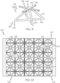
- FIG. 10 which illustrates a cross-sectional view of an example of panel 200, showing the tessellated pattern of core pyramids 236 and off-set grid patterns of stiffeners 228.
- First skin 210 is covered by the array of core pyramids 236 without gaps or overlaps, with the base of each core pyramid 236 meeting the bases of adjacent core pyramids 236 along stiffeners 228 of first skin 210.
- Each core pyramid 236 shares base nodes 238 with adjacent core pyramids 236.
- core pyramids 236 are truncated and each include only two truss members 224.
- the plurality of stiffeners 228 on first skin 210 form a first square grid 246.
- the plurality of stiffeners 228 on second skin 212 form a second square grid 248.
- Each square grid 246, 248 includes a first plurality of parallel stiffeners and a second plurality of parallel stiffeners, which intersect the first plurality and are orthogonal to the first plurality.
- the first and second square grids 246, 248 are offset from each other, such that the intersections of first square grid 246 are vertically aligned with a center of the grid squares of second square grid 248. Intersections of first square grid 246 coincide with base nodes 238, and intersections of second square grid 248 coincide with upper nodes 240 of core pyramids 236.
- Panel 300 is an example of an additively manufactured truss panel, as described above and as referred to as panel 100.
- Panel 300 includes first skin 310 and second skin 312.
- First skin 310 and second skin 312 are connected by truss structure 314.
- First skin 310 is an example of first skin 110 (e.g., Figs. 1B-5 ).
- Second skin 312 is an example of second skin 112 (e.g., Figs. 1B-5 ).
- Truss structure 314 is an example of truss structure 114 (e.g., Figs. 1B-5 ).
- first skin 310 and/or second skin 312 has at least one skin region 356.
- Skin region 356 is an example of skin region 126 ( Figs. 1B-5 ).
- a portion of second skin 212 includes skin region 256 and a portion of second skin 212 includes lattice region 250.
- each of first skin 310 and second skin 312 is planar and rectangular, with inner surface 320.
- First skin 310 is parallel to second skin 312.
- Truss structure 314 includes a plurality of cross or X-shaped truss members 324 extending between nodes 326 of first skin 310 and nodes 326 of second skin 312.
- each truss member 324 extends between node 326 on inner surface 320 of first skin 310 and node 326 on the inner surface 320 of second skin 312.
- Nodes 326 are examples of lattice nodes 130 and/or skin nodes 134 (e.g., Figs. 2-5 ).
- truss structure 314 includes a plurality of circular bosses 328.
- Each boss 328 extends perpendicularly from inner surface 320 of either first skin 310 or second skin 312. The circumferential edge of each boss 328 is filleted to improve printability and self-support of bosses 328.
- boss 328 is located at each of nodes 326. Bosses may facilitate and strengthen connection between truss members 324 and skins 310, 312.
- truss structure 314 includes a plurality of stiffeners 366.
- Stiffeners 366 are examples of skin stiffeners 132 (e.g., Fig. 2 ) and/or lattice stiffeners 136 ( Fig. 3 ).
- stiffeners 366 are non-planar.
- stiffeners 366 are triangular.
- at least one stiffener 366 is disposed on (e.g., coupled to or integrated with) skin region 356, such as inner surface 320 of first skin 310 or inner surface 320 of second skin 312. In these examples, stiffeners 366 may be referred to as skin stiffeners 368.
- stiffeners 366 that extend between upper nodes 364 within lattice region 350 are examples of lattice stiffeners 360 ( Fig. 11 ).
- Stiffeners 366 that extend between upper nodes 364 within skin region 356 are examples of skin stiffeners 368 ( Fig. 11 ).
- Stiffeners 366 that extend between base nodes 362 within skin region 356 are examples of skin stiffeners 368 ( Fig. 11 ).
- Stiffeners 366 that extend between base nodes 362 within lattice region 350 are examples of lattice stiffeners 360 ( Fig. 11 ).
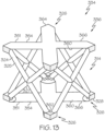
- core boxes 336 of core box frameworks 334 may be described as overlapping in truss structure 314. That is, core box 336 may be described as sharing each one of the four truss members 324 with a respective one of four adjacent core boxes 336 of core box frameworks 334.
- Truss structure 314 may also be described as including a plurality of crisscrossed cylindrical truss members 324. As illustrated in Figs. 12 and 13 , in one or more examples, each of truss members 324 may be described as extending diagonally between node 326 on first skin 310 and node 326 on second skin 312. As illustrated in Fig.
- truss members 324 may form rectangular sides of core box 336, and truss angle 342 may differ between legs 325. In one or more examples, truss angle 342 of each leg 325 is 45 degrees (or approximately 45 degrees).
- Panel 400 is an example of an additively manufactured truss panel, as described above and as referred to as panel 100.
- Panel 400 includes first skin 410 and second skin 412.
- First skin 410 and second skin 412 are connected by truss structure 414.
- First skin 410 is an example of first skin 110 (e.g., Figs. 1B-5 ).
- Second skin 412 is an example of second skin 112 (e.g., Figs. 1B-5 ).
- Truss structure 414 is an example of truss structure 114 (e.g., Figs. 1B-5 ).
- each of first skin 410 and second skin 412 is planar and rectangular, with outer surface 418 and inner surface 420.
- first skin 410 is parallel to second skin 412.
- first skin 410 and second skin 412 are non-parallel.
- first skin 410 and second skin 412 are concentric.
- at least one portion or section of first skin 410 and second skin 412 is parallel and at least another portion or section of first skin 410 and second skin 412 is non-parallel.
- At least one of first skin 410 or second skin 412 includes at least one lattice region 490.
- Lattice region 490 is an example of lattice region 120 ( Figs. 1B-5 ).
- Lattice region 490 includes lattice 491.
- Lattice 491 is an example of lattice 128 ( Figs. 1B-5 ).
- Lattice 491 includes a grid of lattice members 493 and array of openings 492.
- Lattice members 493 are examples of lattice members 122 and openings 492 are examples of openings 124 (e.g., Figs. 2-5 ).
- lattice 491 includes lattice stiffeners 496 that extend along or correspond to lattice members 493. In one or more examples, lattice 491 includes lattice nodes 495 ( Fig. 14 ). Lattice nodes 495 are examples of lattice nodes 130 ( Figs. 2-5 ). Lattice members 493 and lattice stiffeners 496 extend through, cross over, or otherwise meet at lattice nodes 495.
- truss structure 414 includes a plurality of circular bosses 428.
- each boss 428 extends at least approximately perpendicularly from inner surface 420 of either first skin 410 or second skin 412. The circumferential edge of each boss 428 is filleted to improve printability and self-support of the bosses 428.
- Boss 428 is located at each of nodes 426. Bosses 428 may facilitate and strengthen connection between truss members 424 and skins 410, 412.
- interface 458 may be understood to extend linearly across panel 400.
- regions 453, 455 may constitute a rectangular section of panel 400.
- regions 453, 455 may have a non-linear interface and/or any desired shape.
- first region 453 may have a roughly circular shape and may be surrounded by second region 455.
- Interface 458 may lie along boundaries between individual core structures, such that no core structure is divided by the interface.
- second skin 412 outside of reinforced region 457, second skin 412 has a thickness CC. Inside reinforced region 457, second skin 412 has an increased thickness DD. In one or more examples, the increased thickness DD extends inward relative to second skin 412, such that outer surface 418 of second skin 412 remains planar throughout. At the outer boundary of reinforced region 457, second skin 412 includes fillet 459 to provide a gradual transition between the two thicknesses. Fillet 459 may be configured to allow reinforced region 457 to be printed without secondary supports. In one or more examples, reinforced region 457 includes matching thickening of first skin 410.
- lattice members 493 and/or lattice stiffeners 496 extends inward relative to the corresponding first skin 410 and/or second skin 412.
- Lattice members 493 and lattice stiffeners 496 can be configured to all reinforced regions 457 within lattice region 490 to be printed without secondary supports.
- reinforced region 457 may replace shielding that typically includes a separate sheet of metal or other material attached to a sandwich panel. Reinforced region 457 may be configured for radiation shielding of electronics, for example. In such examples, reinforced region 457 may be shaped to match the shielded electronics. Reinforced region 457 be additionally or alternatively configured for thermal management purposes. For example, reinforced region 457 may extend from a thermal output zone of electronic equipment into surrounding portions of the panel to facilitate spreading and rejection of heat generated by the equipment.
- reinforced region 457 may be additionally or alternatively configured for structural reinforcement of panel 400.
- reinforced region 457 may be a thin strip adjacent to an edge of panel 400 intended for welding to another panel. Reinforced region 457 may compensate for loss of strength in the heat affected zone of the weld join.
- reinforced region 457 may extend over a substantial area of second skin 412 to act as an integrated doubler. Such doubling may provide increased panel strength.
- FIGs. 17 and 18 which illustrate examples of panel 400 with integrated closeout walls.
- the integrated closeout walls may replace separate closeouts typically fastened to a sandwich panel.
- panel 400 includes a closeout on each of four edges. Relative to a build orientation, or build axis, the integrated closeout walls of panel 400 may be described as including upper closeout wall 460, lower closeout wall 462, and two side closeout walls 464.
- Fig. 17 is a cross-sectional view of an example of panel 400, sectioned along a plane parallel to the build axis and showing the cross-sectional shape of the upper and lower closeout walls 460, 462.
- lower closeout wall 462 includes the first printed layers of panel 400 and may be deposited directly onto the support of a build plate. Accordingly, lower closeout wall 462 is planar and perpendicular to the build axis and skins 410, 412.
- upper closeout wall 460 includes the final printed layers of panel 400. Therefore, in order to be printed without secondary supports, upper closeout wall 460 has an arched, chamfered, or upside-down V shape.
- Fig. 18 is a cross-sectional view of an example of panel 400, sectioned along a plane perpendicular to the build axis and showing the cross-sectional shape of side closeout walls 464.
- Each side closeout wall 464 may extend parallel to the build axis of the panel. Accordingly, side closeout walls 464 are primarily planar. Side closeout walls 464 include a small chamfer or fillet at each corner, where side closeout walls 464 connect to lower closeout wall 462 and upper closeout wall 460.
- each closeout wall extends a full length of the corresponding edge of panel 400.
- a closeout wall may extend only a portion of the length of the panel and/or may include breaks, openings, or apertures.
- panel 400 may include only one, two, or three of the closeout walls.
- Panel 400 may be designed, configured, and or utilized such that additional localized stiffness and/or strength resulting from the closeout walls can be leveraged.
- panel 400 may be installed into a structure with upper closeout wall 460 proximate a region of greatest expected loading, to take advantage of the stiffness resulting from the additional material included in the upper closeout wall.
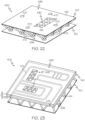
- apertures 470 are located or disposed in skin region 498 of at least one of first skin 410 and/or second skin 412 (e.g., apertures 470 are disposed in skin region 498 of second skin 412 in Fig. 22 ). In one or more examples, apertures 470 are located or disposed in lattice region 490 of at least one of first skin 410 and/or second skin 412. In one or more examples, apertures 470 are disposed in one of skins 410, 412 in addition to any lattice regions 490.
- conduit 480 is configured to receive, contain, transfer, or otherwise direct a coolant through an interior of panel 400. As such, coolant contacts or is otherwise in thermal communication with a portion of both first skin 410 and second skin 412 for heat transfer through the thickness of panel 400 and for heat transfer through each one of first skin 410 and second skin 412.
- Conduit 480 can have any two-dimensional shape or pattern.
- one or more conduits 480 can be connected to or otherwise be in fluid communication with one or more other conduits 480.
- conduit 480 extends from first opening 487 to second opening 488.
- the example of conduit 480 shown in Fig. 29 has an illustrative pattern including multiple turns or paths.
- conduit 480 may include a single continuous path, dead-end portions, variations in size, and/or any desired features.
- openings 487, 488 are disposed along a side or edge portion of panel 400.
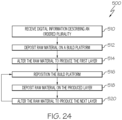
- steps 516 through 520 may be repeated to produce each layer of the plurality of layers of the received digital information, until the last layer is produced.
- the produced first through last layers may then form workpiece 628 as described in the received digital information.
- Workpiece 628 may be removed from printer 610 and post-processed as desired. For example, workpiece 628 may be machined from a build plate of build platform 618, and then fine details or smooth surfaces may be further finished by machining or other methods.
- Clause A1 The aerospace panel of Clause A0, wherein the first skin comprises a first grid of skin stiffeners; the second skin comprises a second grid of skin stiffeners; and each truss member extends between a first node, defined at an intersection of the first grid of stiffeners, and a second node, defined at an intersection of the second grid of stiffeners; where in the one or more lattice regions.
- Clause A13 The aerospace panel of any of Clauses A0-A12, wherein: the plurality of truss members forms an array of core structures; and the density of the core structures varies over at least one region of the aerospace panel.
- Clause A14 The aerospace panel of any of Clauses A0-A13, further comprising: a third skin spaced apart from the second skin; and a second truss structure connecting the second skin to the third skin; wherein the first skin, the second skin, the third skin, the first truss structure, and the second truss structure collectively form the single monolithic joint-free structure.
- Clause C2 The method of Clause C0 or C1, wherein printing the first grid of stiffeners and printing the second grid of stiffeners respectively comprise: printing the first grid of stiffeners to form one or more first grid squares; printing the second grid of stiffeners to one or more second grid squares; where the first grid squares are offset from the second grid squares in a manner such that when the aerospace panel is viewed along a direction normal to the first skin, each one of the first nodes is aligned with a geometric center of one of the second grid squares; and where the one or more grids of lattice stiffeners form one or more lattice grid squares corresponding to either the one or more first grid squares or the one or more second grid squares for the skin in which the grid of lattice stiffeners is located.
- Clause C5. The method of any of Clauses C0-C4, wherein printing the plurality of truss members comprises printing the plurality of truss members as an array of core structures that vary in density over at least one region of the aerospace panel.
- Clause C6 The method of any of Clauses C0-C5, further comprising printing a third skin spaced apart from the second skin, and a second truss structure connecting the second skin to the third skin, while printing the first skin, the second skin, and the first truss structure.
- Clause C8 The method of any of Clauses C0-C7, wherein printing the first skin and the second skin comprises printing at least one of the first skin and the second skin with an internal channel embedded in the first skin and/or the second skin.
- Clause C 11 The method of any of Clauses C0-C9, wherein the printing material is comprised of a metal or metal alloy such as aluminum and its alloys, titanium and its alloys, niobium and its alloys, Inconel, or any combination thereof.
- a metal or metal alloy such as aluminum and its alloys, titanium and its alloys, niobium and its alloys, Inconel, or any combination thereof.
- Clause D1 The method of Clause D0, wherein: printing the first skin and printing the second skin respectively comprise printing a first grid of stiffeners with the first skin, and printing a second grid of stiffeners with the second skin and printing the plurality of truss members comprises printing each truss member to extend between a first node, defined at an intersection of the first grid of stiffeners, and a second node, defined at an intersection of the second grid of stiffeners, in the at least one lattice region, the lattice grid comprises one or more grids of lattice stiffeners.
- Clause D6 The method of any of Clauses D0-D5, further comprising printing a third skin spaced apart from the second skin, and a second truss structure connecting the second skin to the third skin, while printing the first skin, the second skin, and the first truss structure.
- illustrative examples described herein enable the tailoring of the through-panel thermal conductivity of the panel for thermal management by varying (e.g., increasing or decreasing) the density of the truss structure of the panel.
- the term “approximately” refers to or represents a condition that is close to, but not exactly, the stated condition that still performs the desired function or achieves the desired result.
- the term “approximately” refers to a condition that is within an acceptable predetermined tolerance or accuracy, such as to a condition that is within 10% of the stated condition.
- the term “approximately” does not exclude a condition that is exactly the stated condition.
- the term “substantially” refers to a condition that is essentially the stated condition that performs the desired function or achieves the desired result.
Landscapes
- Engineering & Computer Science (AREA)
- Aviation & Aerospace Engineering (AREA)
- Chemical & Material Sciences (AREA)
- Materials Engineering (AREA)
- Manufacturing & Machinery (AREA)
- Architecture (AREA)
- Remote Sensing (AREA)
- Mechanical Engineering (AREA)
- Structural Engineering (AREA)
- Civil Engineering (AREA)
- Physics & Mathematics (AREA)
- Electromagnetism (AREA)
- Moulding By Coating Moulds (AREA)
- Lining Or Joining Of Plastics Or The Like (AREA)
- Laminated Bodies (AREA)
Abstract
Description
- The present disclosure relates generally to aerospace structures and, more particularly, to additively manufactured aerospace panels and methods for additively manufacturing aerospace panels.
- Aerospace presents a uniquely hostile environment for vehicles. Space is a very hostile environment for spacecraft, such as satellites. Thermal management in particular is challenging in space or in high-speed applications, in addition to the danger of damaging radiation and foreign object damage (e.g., from orbital debris impacts). Many aerospace vehicles are constructed of composite materials, such as sandwich-structure panels, which are strong and light. However, such panels typically include a core material bonded between two thin skins, which results in high thermal impedance. Composite sandwich-structure panels can also be expensive and labor intensive to manufacture. Wrapping and extraction of tooling, precise placement of individual plies, and multiple stages of curing and layup each require significant time and touch labor. For localized features such as shielding and reinforcement, separate parts are attached post-production, requiring further expense and labor.
- Additive Manufacturing (AM) is quickly gaining popularity in many industries as a method of rapid production at relatively low cost. AM, sometimes known as 3D printing, can be used to create a solid object from a 3D model by building the object incrementally. AM typically applies a raw material that is then selectively joined or fused to create the desired object. The raw material is typically applied in layers, where the thickness of the individual layers can depend upon the particular techniques used.
- Often the raw material is in the form of granules or powder, applied as a layer, and then selectively fused by a heat source. In many cases, the upper surface of a bed of such material is fused, and the growing workpiece is then lowered slightly into the bed itself. A fresh layer of raw material is then applied to the bed, and the next layer is fused onto the previous one. The granular raw material may include, for example, thermoplastic polymer, thermoset polymer, metal powder, metal alloy powder, or ceramic powder, which may be fused using a computer-controlled heat source, such as a scanning laser or scanning electron beam. Exemplary methods include selective laser melting (SLM), direct metal laser sintering (DMLS), selective laser sintering (SLS), fused deposition modelling (FDM), and electron beam melting (EBM), among others.
- Conventional part designs used for subtractive manufacturing or composite laminate construction may be inefficient or even unworkable for AM. Depending on the process and material used, unsupported features may collapse, delicate features may be rendered with insufficient clarity, and/or warping and cracking may occur. New designs maintaining functionality of conventional parts while enabling efficient use of AM methods are needed.
- Disclosed are examples of an aerospace panel, an aerospace vehicle, and examples of systems, apparatuses, and methods relating to additively manufactured aerospace panels. The following is a non-exhaustive list of examples, which may or may not be claimed, of the subject matter according to the present disclosure.
- In one or more examples, the disclosed aerospace panel includes: a first skin; a second skin spaced apart from the first skin; and a first truss structure connecting the first skin to the second skin. The first truss structure includes a plurality of truss members. Each truss member is integral with the first skin and the second skin, such that the first skin, the second skin, and the first truss structure collectively form a single monolithic joint-free structure. At least one of the first skin and the second skin includes at least one lattice region defining a lattice configured to eliminate secondary printing support. The at least one lattice region includes a lattice grid and an array of openings.
- In one or more examples of the disclosed aerospace panel, the first skin has a first grid of stiffeners, the second skin has a second grid of stiffeners, and each truss member extends between a first node, defined at an intersection of the first grid of stiffeners, and a second node, defined at an intersection of the second grid of stiffeners. In the at least one lattice region, the lattice grid includes one or more grids of lattice stiffeners.
- In one or more examples of the disclosed aerospace panel, the first grid of stiffeners defines one or more first grid squares. The second grid of stiffeners defines one or more second grid squares. The first grid squares are offset from the second grid squares in a manner such that when the aerospace panel is viewed along a direction normal to the first skin, each one of the first nodes is aligned with a geometric center of one of the second grid squares. The one or more grids of lattice stiffeners defines one or more lattice grid squares corresponding to either the one or more first grid squares or the one or more second grid squares for the skin in which the grid of lattice stiffeners is located.
- In one or more examples of the disclosed aerospace panel, at least one of the first grid of skin stiffeners and the second grid of skin stiffeners is non-planar.
- In one or more examples, the disclosed aerospace panel includes a closeout wall extending between the first skin and the second skin along at least one edge of the aerospace panel. The first skin, the second skin, the first truss structure, and the closeout wall collectively form the single monolithic joint-free structure.
- In one or more examples of the disclosed aerospace panel, the plurality of truss members includes a plurality of X-shaped truss members. Each one of the X-shaped truss members extends between a pair of first nodes on the first skin and a pair of second nodes on the second skin.
- In one or more examples of the disclosed aerospace panel, the plurality of truss members forms an array of core structures. The density of the core structures varies over at least one region of the aerospace panel.
- In one or more examples, the disclosed aerospace panel includes a third skin spaced apart from the second skin and a second truss structure connecting the second skin to the third skin. The first skin, the second skin, the third skin, the first truss structure, and the second truss structure collectively form the single monolithic joint-free structure.
- In one or more examples, the disclosed aerospace panel has a primary axis parallel to a lengthwise direction of the first skin and the second skin and a secondary axis perpendicular to the primary axis and normal to the first skin and the second skin. Each one of the truss members is oriented at a first truss angle of 35-50 degrees (or approximately 35-50 degrees) relative to the secondary axis when the aerospace panel is viewed along a direction perpendicular to both the primary axis and the secondary axis. Each one of the truss members is oriented at a second truss angle of 35-50 degrees (or approximately 35-50 degrees) relative to the secondary axis when the aerospace panel is viewed along the primary axis.
- In one or more examples of the disclosed aerospace panel, at least one of the first skin and the second skin has an internal channel embedded respectively in the first skin and/or the second skin.
- In one or more examples, the disclosed aerospace vehicle includes a body having one or more aerospace panels. Each one of the aerospace panels includes a first skin, a second skin spaced apart from the first skin, and a first truss structure connecting the first skin to the second skin. The first truss structure includes a plurality of truss members. Each one of the truss members is integral with the first skin and the second skin, such that the first skin, the second skin, and the first truss structure collectively form a single monolithic joint-free structure. At least one of the first skin and the second skin includes at least one lattice region defining a lattice configured to eliminate secondary printing support. The at least one lattice region includes a grid of lattice stiffeners and an array of openings.
- In one or more examples, the disclosed method for manufacturing an aerospace panel includes steps of printing a first skin and a second skin spaced apart from the first skin, while simultaneously printing a plurality of truss members of a first truss structure connecting the first skin to the second skin, thereby resulting in a single monolithic joint-free structure. At least one of the first skin and the second skin includes at least one lattice region defining a lattice configured to eliminate secondary printing support. The at least one lattice region includes a lattice grid and an array of openings.
- In one or more examples of the disclosed method, the step of printing the first skin and printing the second skin respectively includes a step of printing a first grid of stiffeners with the first skin and a step of printing a second grid of stiffeners with the second skin. The step of printing the plurality of truss members includes a step of printing each truss member to extend between a first node, defined at an intersection of the first grid of stiffeners, and a second node, defined at an intersection of the second grid of stiffeners.
- In one or more examples of the disclosed method, the step of printing the first grid of stiffeners and the step of printing the second grid of stiffeners, respectively, include a step of printing the first grid of stiffeners to form one or more first grid squares and a step of printing the second grid of stiffeners to one or more second grid squares. The first grid squares are offset from the second grid squares in a manner such that when the aerospace panel is viewed along a direction normal to the first skin, each one of the first nodes is aligned with a geometric center of one of the second grid squares. The one or more grids of lattice stiffeners form one or more lattice grid squares corresponding to either the one or more first grid squares or the one or more second grid squares for the skin in which the grid of lattice stiffeners is located.
- In one or more examples, the disclosed method includes a step of printing a closeout wall while printing the first skin, the second skin, and the first truss structure. The closeout wall extending between the first skin and the second skin along at least one edge of the aerospace panel.
- In one or more examples of the disclosed method, the step of printing the plurality of truss members includes a step of printing a plurality of X-shaped truss members. Each one of the X-shaped truss members extending between a pair of first nodes on the first skin and a pair of second nodes on the second skin.
- In one or more examples of the disclosed method, the step of printing the plurality of truss members includes a step of printing the plurality of truss members as an array of core structures that varies in density over at least one region of the aerospace panel.
- In one or more examples, the disclosed method includes a step of printing a third skin spaced apart from the second skin and a step of printing a second truss structure connecting the second skin to the third skin, while printing the first skin, the second skin, and the first truss structure.
- In one or more examples of the disclosed method, the aerospace panel has a primary axis parallel to a lengthwise direction of the first skin and the second skin and a secondary axis perpendicular to the primary axis and normal to the first skin and the second skin. The step of printing the plurality of truss members includes a step of printing each one of the truss members at a first truss angle of 35-50 degrees (or approximately 35-50 degrees) relative to the secondary axis, when the aerospace panel is viewed along a direction perpendicular to both the primary axis and the secondary axis, and at a second truss angle of 35-50 degrees (or approximately 35-50 degrees) relative to the secondary axis, when the aerospace panel is viewed along the primary axis.
- In one or more examples of the disclosed method, the step of printing the first skin and the second skin includes a step of printing at least one of the first skin and the second skin with an internal channel embedded in the first skin and/or the second skin.
- In one or more examples of the disclosed method, the step of printing the first skin, the second skin, and the first truss structure includes a step of printing, using an additive manufacturing apparatus, the aerospace panel in a manner such that the lengthwise direction of the first skin and the second skin is parallel to a build direction of the additive manufacturing apparatus.
- Features, functions, and advantages may be achieved independently in various examples of the present disclosure, or may be combined in yet other examples, further details of which can be seen with reference to the following description and drawings. Other examples of the aerospace panel, the aerospace vehicle, and the methods disclosed herein, will become apparent from the following detailed description, the accompanying drawings, and the appended claims.
-
-
Fig. 1A is a schematic illustration of an example of an aerospace vehicle; -
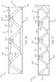
Fig. 1B is a schematic illustration of an example of a portion of an additively manufactured aerospace panel of the aerospace vehicle; -
Fig. 1C is a schematic illustration of an example of a portion of the additively manufactured aerospace panel of the aerospace vehicle; -
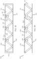
Fig. 1D is a schematic illustration of an example of a portion of the additively manufactured aerospace panel of the aerospace vehicle; -
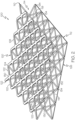
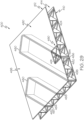
Fig. 2 is a schematic, isometric view of an example of an additively manufactured panel; -
Fig. 3 is a schematic, isometric view of an example of the additively manufactured panel; -
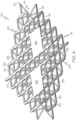
Fig. 4 is a schematic, isometric view of an example of the additively manufactured panel; -
Fig. 5 is a schematic, isometric view of an example of the additively manufactured panel; -
Fig. 6 is a schematic, isometric view of an example of the additively manufactured panel; -
Fig. 7 is a schematic elevation, sectional view of an example of a portion of the additively manufactured panel; -
Fig. 8 is a schematic, isometric view of an example of a core structure of the additively manufactured panel; -
Fig. 9 is a schematic, isometric view of an example of a core structure of the additively manufactured panel; -
Fig. 10 is a schematic, cross-sectional view of an example of the additively manufactured panel ofFig. 6 taken along lines 10-10; -
Fig. 11 is a schematic, elevation, sectional view of an example of a portion of the additively manufactured panel; -
Fig. 12 is a schematic, isometric view of an example of the core structure of the additively manufactured panel; -
Fig. 13 is a schematic, isometric view of an example of the core structure of the additively manufactured panel; -
Fig. 14 is a schematic, elevation, sectional view of an example of the additively manufactured panel; -
Fig. 15 is a schematic, elevation view of an example of the additively manufactured panel with a variation in core density; -
Fig. 16 is a schematic, elevation view of an example of the additively manufactured panel with a localized thickening of the skins; -
Fig. 17 is a schematic, elevation view of an example of the additively manufactured panel with closeout structures; -
Fig. 18 is a schematic, elevation view of an example of the additively manufactured panel ofFig. 17 , from an orthogonal direction; -
Fig. 19 is a schematic, elevation view of an example of the additively manufactured panel with an integrated access hole; -
Fig. 20 is a schematic, isometric view of an example of the additively manufactured panel ofFig. 19 ; -
Fig. 21 is a schematic, elevation view of an example of the additively manufactured panel with multiple integrated mounting holes; -
Fig. 22 is a schematic, isometric view of an example of the additively manufactured panel ofFig. 21 ; -
Fig. 23 is a schematic, isometric view of an example of the additively manufactured panel with an internal channel embedded in a skin; -
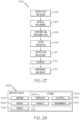
Fig. 24 is a flow chart depicting an example of a method for additive manufacturing; -
Fig. 25 is a schematic, block diagram of an example of an additive manufacturing apparatus; -
Fig. 26 is a flow chart depicting an example of a method for additively manufacturing a panel; -
Fig. 27 is a flow diagram of an example of an aerospace vehicle manufacturing and service method; -
Fig. 28 is a schematic block diagram of an example of an aerospace vehicle; and -
Fig. 29 a schematic, isometric view of an example of the additively manufactured panel with an integrated conduit extending between skins. - Various examples of an additively manufactured aerospace panel having a truss structure, as well as related methods, are described below and illustrated in the associated drawings. Unless otherwise specified, an additively manufactured aerospace panel in accordance with the present teachings, and/or its various components may, but are not required to, contain at least one of the structures, components, functionalities, and/or variations described, illustrated, and/or incorporated herein. Furthermore, unless specifically excluded, the process steps, structures, components, functionalities, and/or variations described, illustrated, and/or incorporated herein in connection with the present teachings may be included in other similar devices and methods, including being interchangeable between disclosed examples. The following description of various examples is merely illustrative in nature and is in no way intended to limit the disclosure, its application, or uses. Additionally, the advantages provided by the examples described below are illustrative in nature and not all examples provide the same advantages or the same degree of advantages.
- This Detailed Description includes the following sections, which follow immediately below: (1) Overview; (2) Examples, Components, and Alternatives; (3) Illustrative Combinations and Additional Examples; (4) Advantages, Features, and Benefits; and (5) Conclusion. The Examples, Components, and Alternatives section is further divided into subsections A through H, each of which is labeled accordingly.
- In general, an additively manufactured aerospace panel in accordance with the present teachings includes two skins connected by a truss structure. The panel is a single additively manufactured unit. The panel may also be described as a sandwich structure, sandwich panel, or sandwich-structured composite material, having two face sheets connected by one or more core structures.
-
Fig. 1A is a schematic illustration of an example ofaerospace vehicle 102, such as a spacecraft. In the illustrated example,aerospace vehicle 102 is depicted as a satellite, such as a communications satellite. In other examples,aerospace vehicle 102 may be a commercial airplane, a helicopter, a high-speed aircraft, an astronomical space observatory, a launch vehicle, an orbital space station, and/or any air-going or space-going craft. - In one or more examples,
aerospace vehicle 102 includes abody 104.Body 104 generally serves as the primary structure ofaerospace vehicle 102.Body 104 includes one or more additively manufactured truss panels, including panel 100 (Figs. 1B-1D ).Panel 100 may be used for interior or exterior structures ofaerospace vehicle 102, and/or may be used for secondary structures, detachable modules, equipment housings, and/or any appropriate structure ofaerospace vehicle 102. Advantageously, in some examples,panel 100 may include features configured for the challenges of the space environment. - Referring now to
Figs. 1B-1D , which schematically illustrate examples of a portion ofpanel 100. In one or more examples,panel 100 includesfirst skin 110,second skin 112, andtruss structure 114.First skin 110 is spaced fromsecond skin 112. - In one or more examples of
panel 100,first skin 110 andsecond skin 112 are parallel or at least approximately parallel to one another (e.g.,Fig. 1B ). In one or more examples ofpanel 100, at least a portion offirst skin 110 and at least a portion ofsecond skin 112 non-parallel to one another (e.g.,Fig. 1C ). In one or more examples ofpanel 100,first skin 110 andsecond skin 112 are concentric to one another (e.g.,Fig. 1D ). - In one or more examples of
panel 100,first skin 110 andsecond skin 112 are joined together on at least one edge. - In one or more examples,
panel 100,first skin 110, andsecond skin 112 may be understood to have a planar extent. As an example,panel 100,first skin 110, andsecond skin 112 are generally planar (e.g.,Fig. 1B ) when viewed along at least orthogonal axis or direction. For example,panel 100 may take the form of a flat panel. In one or more examples,panel 100,first skin 110, andsecond skin 112 have curvature and/or more complex geometry. As an example,panel 100,first skin 110 and/orsecond skin 112 are non-planar or otherwise include some degree or curvature or contour in one or more directions (e.g.,Figs. 1C and 1D ). - In one or more examples,
truss structure 114 is connected tofirst skin 110 and tosecond skin 112.First skin 110 andsecond skin 112 are in turn connected to one another bytruss structure 114.Truss structure 114 includes a plurality oftruss members 118. In one or more examples, opposed ends of one or more oftruss members 118 is coupled tofirst skin 110 andsecond skin 112. In one or more examples, opposed ends of eachtruss member 118 is integral withfirst skin 110 andsecond skin 112, such thatfirst skin 110,second skin 112, andtruss structure 114 collectively form a single, monolithic joint-free structure. - In one or more examples,
truss structure 114 includes an array ofcore structures 116. Each one ofcore structures 116 includes or takes the form of a framework oftruss members 118 having any appropriate geometry. In one or more examples, the geometry ofcore structures 116 is uniform overpanel 100. In one or more examples, the geometry ofcore structures 116 varies according to location inpanel 100. For example,core structures 116 may vary according to expected nonuniform loading ofpanel 100 and/orcore structures 116 may vary according to a curvature ofpanel 100,first skin 110, and/orsecond skin 112. In one or more examples,core structures 116 are arranged in a grid, a repeating pattern, and/or in any effective manner. - In one or more examples of
panel 100, at least one offirst skin 110 and/orsecond skin 112 has at least onelattice region 120. At least onelattice region 120 defines or takes the form of lattice 128 (e.g., a lattice structure). Generally, in one or more examples,lattice 128 oflattice region 120 is configured to eliminate secondary printing support during additive manufacture ofpanel 100.Lattice 128 of at least onelattice region 120 includes a grid oflattice members 122 and an array ofopenings 124.Lattice 128 includes or takes the form of a pattern or structure made of strips of material (e.g., lattice members 122) that cross over each other, thereby leaving holes (e.g., openings 124) in between. In one or more examples, the strips of material (e.g., lattice members 122) of thelattice 128 cross over each other in a grid, perpendicularly, diagonally, or a combination thereof. - In one or more examples,
lattice 128 includes a plurality oflattice stiffeners 136. In one or more examples, eachlattice stiffener 136 is disposed on an inner surface oflattice 128. For example,lattice stiffener 136 is coupled to or is integrated withlattice members 122.Lattice stiffener 136 provides stiffening and structural rigidity tolattice members 122. In one or more examples,lattice stiffener 136 increases the thickness oflattice 128 along eachlattice member 122. - In one or more examples, at least one of
first skin 110 andsecond skin 112 also includes at least oneskin region 126.Skin region 126 includes or takes the form of solid, sheet structure made of continuous material that has no holes or openings. In the examples illustrated inFigs. 1B-1D , bothfirst skin 110 andsecond skin 112 include at least onelattice region 120 and at least oneskin region 126. - In one or more examples,
panel 100 is additively manufactured, or 3D-printed, as a single, unitary structure. As such,panel 100 may also be described as monolithic. In other words,first skin 110,second skin 112, andtruss structure 114 are additively manufactured, or printed, together andpanel 100 is formed of printed material without joints or seams. As such,panel 100 may have a build axis. Aspanel 100 is printed, layers of material are deposited in a plane perpendicular to the build axis. In one or more examples, the build axis is parallel to the planar extent offirst skin 110 and/orsecond skin 112. In such examples,panel 100 may also be described as being printed withfirst skin 110 andsecond skin 112 in a vertical orientation. Consequently, in such examples,first skin 110,second skin 112, andtruss structure 114 may all be printed concurrently rather than sequentially. - In one or more examples,
truss members 118 oftruss structure 114, or of eachcore structure 116, are oriented and/or shaped relative to the build axis such thattruss members 118 are self-supporting during printing. That is, eachcore structure 116 can be printed without need for secondary supports or removal of supporting material subsequent to printing. In one or more examples,truss members 118 extend at an angle of no more than forty-five degrees relative to the build axis. In one or more examples,panel 100 includes additional structures and/or features. In such examples, each structure and/or feature may be oriented, shaped, and/or configured to be self-supporting during printing.Panel 100 may be configured for manufacture without post-processing such as machining subsequent to printing. - In one or more examples,
panel 100 is customized according to intended use, structural function, and/or placement within an aerospace vehicle, such as a spacecraft. Additive manufacture may allow flexibility in design ofpanel 100 and incorporation of localized features. In one or more examples,panel 100 includes localized thickening for structural reinforcement, thermal spreading, and/or heat dissipation. In one or more examples,panel 100 includes integrated conductors and/or attachment features, such as fastener-engaging structures. In one or more examples,truss structure 114 is configured to improve resistance to an expected primary loading mode or to be inhomogeneous to match expected load inhomogeneity. Design flexibility and localized features may be especially important for aerospace panels, and challenges of the space environment such as radiation, micrometeoroid, and orbital debris (MMOD) impact, and thermal conditions. - The following sections describe exemplary additively manufactured aerospace panels as well as related systems and/or methods. The examples in these sections are intended for illustration and should not be interpreted as limiting the entire scope of the present disclosure. Each section may include one or more distinct examples, and/or contextual or related information, function, and/or structure.
- Referring to
Figs. 2-5 , which schematically illustrate examples of a portion ofpanel 100, this section describes an illustrative aerospace panel, referred to herein aspanel 100.Panel 100 is an example of an additively manufactured truss panel.Panel 100 includesfirst skin 110 andsecond skin 112.First skin 110 andsecond skin 112 are connected bytruss structure 114. In one or more examples ofpanel 100, at least one offirst skin 110 and/orsecond skin 112 has at least one region defining a lattice, referred to herein aslattice region 120. In one or more examples ofpanel 100,lattice region 120 includes a lattice grid, referred to herein aslattice 128.Lattice 128 includes a grid oflattice members 122 and an array ofopenings 124. The limits oflattice region 120 can correspond to any combination of the following: underlying geometric features offirst skin 110 and/or second skin 112 (e.g., locations of stiffeners), located to enhance the desired local properties ofpanel 100, or situated discretionarily as needed to meet overall panel design constraints. - In the examples illustrated in
Figs. 2-5 ,first skin 110 andsecond skin 112 are generally planar and parallel to each other and, thereby,panel 100 is generally planar. However, in other examples,first skin 110 andsecond skin 112 can be non-planar and/or non-parallel (e.g., as illustrated inFigs. 1C and 1D ).Figs. 2-5 illustrate examples of different configurations oflattice region 120 andskin region 126 offirst skin 110 and/orsecond skin 112. - As illustrated in
Fig. 2 , in one or more examples,first skin 110 is formed entirely oflattice region 120. In other words,first skin 110 forms a continuous, lattice face sheet ofpanel 100.Second skin 112 is formed entirely ofskin region 126. In other words,second skin 112 forms a continuous, solid face sheet ofpanel 100. - As illustrated in
Fig. 3 , in one or more examples,first skin 110 is formed entirely oflattice region 120. In other words,first skin 110 forms a continuous, lattice face sheet ofpanel 100.Second skin 112 is formed entirely oflattice region 120. In other words,second skin 112 forms a continuous, lattice face sheet ofpanel 100. - As illustrated in
Fig. 4 , in one or more examples, at least one offirst skin 110 and second skin 112 (e.g.,first skin 110 inFig. 4 ) includes or is formed oflattice region 120 andskin region 126. In some examples, including the illustrated example,first skin 110 includes two portions formed by skin region 126 (e.g., two skin regions 126) and the remaining portion ofsecond skin 112 is formed bylattice region 120. In the illustrated example,skin regions 126 are located on an interior boundary offirst skin 110 and are surrounded bylattice region 120. However, in other examples,first skin 110 and/orsecond skin 112 can have any number ofskin regions 126,skin regions 126 can be disposed at any suitable location along the extend offirst skin 110 and/orsecond skin 112, andskin regions 126 can have any suitable size and/or two-dimensional geometry. In any of these examples,lattice region 120 andskin region 126 share a boundary and extend from and/or between one another to form the extent offirst skin 110 and/orsecond skin 112. - As illustrated in
Fig. 5 , in one or more examples, at least one offirst skin 110 and second skin 112 (e.g.,first skin 110 inFig. 5 ) includes or is formed oflattice region 120 andskin region 126. In some examples, including the illustrated example,first skin 110 includes a boundary portion formed byskin region 126 and the remaining interior portion ofsecond skin 112 is formed bylattice region 120. In some examples, including the illustrated example,skin regions 126 are located along and form the perimeter edges offirst skin 110 and surroundlattice region 120. However, in other examples, any one or more of the perimeter edges offirst skin 110 and/orsecond skin 112 can be formed entirely bylattice region 120 or can have a portion formed byskin region 126 and a portion formed bylattice region 120. Additionally, the example illustrated inFig. 5 can also include one ormore skin regions 126 located on an interior portion and surrounded by the perimeter portions formed byskin region 126. - In other non-illustrated examples,
lattice region 120 andskin region 126 offirst skin 110 and/orsecond skin 112 can have any one of various patterns, layouts, or configurations. The pattern, layout, or configuration of one ormore lattice regions 120 and one ormore skin regions 126 can depend on the size ofpanel 100, the end use or application ofpanel 100, the attachment locations ofpanel 100 to another structure, and the like. - As illustrated in
Figs. 2-5 , regardless of the layout or configuration oflattice region 120 andskin region 126 offirst skin 110 and/orsecond skin 112,first skin 110 andsecond skin 112 are connected totruss structure 114 and are connected to each other bytruss structure 114. In one or more regions offirst skin 110 and/orsecond skin 112 formed fromskin region 126, an end oftruss member 118 is coupled to or is integral withskin region 126. In one or more regions offirst skin 110 and/orsecond skin 112 formed fromlattice region 120, an end oftruss member 118 is coupled to or is integral withlattice region 120. - As illustrated in
Figs. 2-5 , in examples ofpanel 100 having at least onelattice region 120,lattice 128 oflattice region 120 includes a plurality oflattice members 122 arranged in a grid or that otherwise intersect or cross over each other (e.g., perpendicularly and/or diagonally) to form a plurality ofopenings 124 arranged in an array betweenlattice members 122. One end of eachtruss member 118 oftruss structure 114 is coupled to or integrated withfirst skin 110 orsecond skin 112 atlattice node 130 oflattice region 120. In one or more examples, one of a plurality oflattice nodes 130 oflattice region 120 is located at the intersection of two ormore lattice members 122 oflattice 128. For example, eachlattice member 122 extends in a grid, perpendicularly, or diagonally between twolattice nodes 130. - As illustrated in
Fig. 2 , in examples ofpanel 100 having at least oneskin region 126, one end of eachtruss member 118 oftruss structure 114 is coupled to or integrated withfirst skin 110 orsecond skin 112 atskin node 134 ofskin region 126. - As illustrated in
Fig. 2 , in examples ofpanel 100 in whichlattice region 120 offirst skin 110 isopposite skin region 126 ofsecond skin 112, each one oflattice nodes 130 offirst skin 110 is generally aligned with one ofskin nodes 134 ofsecond skin 112 along an axis that passes perpendicularly throughfirst skin 110 andsecond skin 112. In one or more examples, eachtruss member 118 extends betweenlattice node 130 offirst skin 110 andskin node 134 ofsecond skin 112. In one or more examples, eachtruss member 118 extends diagonally betweenlattice node 130 offirst skin 110 andskin node 134 ofsecond skin 112. - As illustrated in
Fig. 3 , in examples ofpanel 100 in whichlattice region 120 offirst skin 110 isopposite lattice region 120 ofsecond skin 112, each one oflattice nodes 130 offirst skin 110 is generally aligned with one oflattice nodes 130 ofsecond skin 112 along an axis that passes perpendicularly throughfirst skin 110 andsecond skin 112. In one or more examples, eachtruss member 118 extends betweenlattice node 130 offirst skin 110 andlattice node 130 ofsecond skin 112. In one or more examples, eachtruss member 118 extends diagonally betweenlattice node 130 offirst skin 110 andlattice node 130 ofsecond skin 112. - Referring again to
Fig. 2 , in examples ofpanel 100 in whichfirst skin 110 orsecond skin 112 includes at least oneskin region 126,skin region 126 can also include a plurality ofskin stiffeners 132. Eachskin stiffener 132 is coupled to or is integrated withskin region 126 and extends between twoskin nodes 134. In one or more examples, eachskin stiffener 132 extends diagonally between twoskin nodes 134. - Referring now to
Figs. 6-9 , this section describes an illustrative pyramidal truss aerospace panel, referred to herein aspanel 200.Panel 200 is an example of an additively manufactured truss panel, as described herein above and referred to aspanel 100.Panel 200 includesfirst skin 210 andsecond skin 212.First skin 210 andsecond skin 212 are connected bytruss structure 214.First skin 210 is an example of first skin 110 (e.g.,Figs. 1B-5 ).Second skin 212 is an example of second skin 112 (e.g.,Figs. 1B-5 ).Truss structure 214 is an example of truss structure 114 (e.g.,Figs. 1B-5 ). - Referring to
Fig. 6 , which illustrated an example ofpanel 200. In one or more examples, at least one offirst skin 210 and/orsecond skin 212 collectively has at least onelattice region 250.Lattice region 250 is an example of lattice region 120 (e.g.,Figs. 1B-5 .) In one or more examples,lattice region 250 includeslattice 251.Lattice 251 is an example of lattice 128 (e.g.,Figs. 2-5 ).Lattice 251 includes a grid oflattice members 254 and array ofopenings 252.Lattice members 254 are examples oflattice members 122 andopenings 252 are examples of openings 124 (e.g.,Figs. 2-5 ). - The limits of
lattice region 250 can correspond to any combination of the following: underlying geometric features of theskins 210, 212 (e.g., locations of stiffeners), located to enhance the desired local properties ofpanel 200, or situated discretionarily as needed to meet overall panel design constraints.Truss structure 214 may be configured to improve a selected strength value ofpanel 200, such as resistance to shearing, tension, or buckling. In one or more examples,truss structure 214 is configured for resistance to buckling loads. - In one or more examples of
panel 200, at least one offirst skin 210 and/orsecond skin 212 has at least oneskin region 256. In the example illustrated inFig. 6 , a portion ofsecond skin 212 includesskin region 256 and a portion ofsecond skin 212 includeslattice region 250. - As described further below, each of
first skin 210,second skin 212, andtruss structure 214 are shaped, featured, and/or configured according to desired properties ofpanel 200.Panel 200 may be configured for use in any aerospace vehicle. In one or more examples,panel 200 is configured for spacecraft.Panel 200 may function as a structural component, as part of a thermal management system, as radiation shielding, and/or as micrometeoroid and orbital debris (MMOD) shielding for spacecraft, for example. - In one or more examples,
panel 200 includes any material or materials appropriate to additive manufacture. Such materials include, but are not limited to, a polymer, a plaster, a ceramic, a metal, or a composite. Polymer materials include thermoplastics (e.g., polyvinyl alcohol (PVA), polydimethylsiloxane (PDMS), polyether-ketone-ketone (PEKK), polylactic acid (PLA), nylon, acrylonitrile butadiene styrene (ABS) plastics, Polycarbonate (PC), polyetherimide (PEI), polyimide (PI), polystyrene (PS), polytetrafluoroethylene (PTFE), acrylics such as poly(methyl methacrylate), polypropylene (PP), polyethylene (PE)), thermosets (e.g., photopolymer resin, epoxy), hydrogels, or any combination thereof. Metals include any high strength, high-temperature metal or metal alloy, such as aluminum and its alloys, titanium and its alloys, niobium and its alloys, Inconel, or any combination thereof. In one or more examples,panel 200 includes a laser sintered metal alloy and is manufactured by direct laser metal sintering. In one or more examples, an aluminum alloy may offer an advantageous strength-to-weight ratio and provide effective heat radiation and/or rejection. - Manufacture of
first skin 210,second skin 212, andtruss structure 214 as a unitary (e.g., metal) structure may improve thermal performance and heat rejection of the panel by removing impedance caused by adhesive materials in traditionally manufactured sandwich panels. Such thermal properties may be especially advantageous for thermal management in a space environment. Additive manufacture offirst skin 210 andsecond skin 212 to include at least onelattice region 250 reduces weight, materials, cost, and cycle time associated withmanufacturing panel 200. - In one or more examples,
panel 200 is approximately half an inch thick and 3.5 inches wide by 6 inches long (1.3 cm thick and 8.9 cm wide by 15 cm long). Dimensions ofpanel 200 may be constrained by the capacity of the apparatus used in manufacture ofpanel 200. Toform panel 200 having desired dimensions beyond the capacity of a selected additive manufacturing apparatus, a plurality of panels, such aspanel 200, may be printed separately and joined together. For example,panel 200 may be welded, bonded, and/or fastened to another panel as described herein. - Referring still to
Fig. 6 , in one or more examples, each offirst skin 210 andsecond skin 212 is planar and rectangular. Each offirst skin 210 andsecond skin 212 hasouter surface 218 andinner surface 220 that is opposite and parallel toouter surface 218. In one or more examples,first skin 210 is parallel tosecond skin 212. In other examples, at least a portion offirst skin 210 and at least a portion ofsecond skin 212 are non-parallel. In one or more examples, each offirst skin 210 andsecond skin 212 has a uniform thickness throughout. In one or more examples, each offirst skin 210 andsecond skin 212 are identical. In one or more examples, each offirst skin 210 andsecond skin 212 has a thickness of 0.02 inches or approximately 0.02 inches (0.5 mm or approximately 0.5 mm). In one or more examples, as discussed further in section D below, one or both offirst skin 210 andsecond skin 212 may vary in thickness and/or one offirst skin 210 orsecond skin 212 may have a greater thickness than the other. - In one or more examples,
panel 200 hasprimary axis 222, which extends parallel tofirst skin 210 andsecond skin 212. In one or more examples,primary axis 222 is parallel to a longer side of the rectangular shape of thefirst skin 210 andsecond skin 212. In one or more examples,panel 200 is additively manufactured according to (e.g., along or in the direction of)primary axis 222, which may also be described as a build axis or a vertical axis. In other words,panel 200 is printed such thatprimary axis 222 is aligned with a build direction of an additive manufacturing apparatus. For example,panel 200 is printed onto a build plate by depositing layers of material parallel to the build plate. In such an example,panel 200 is printed withprimary axis 222 perpendicular to the build plate. - Because
primary axis 222 is parallel tofirst skin 210 andsecond skin 212,first skin 210 andsecond skin 212 may be described as being printed vertically. Each ofouter surface 218 andinner surface 220 offirst skin 210 andsecond skin 212 may extend in the build direction throughout printing. In examples offirst skin 210 andsecond skin 212 withlattice regions 250, the primary axis oflattice region 250 is aligned with the primary axis of the corresponding one offirst skin 210 andsecond skin 212 andlattice 251 oflattice region 250 extends in the build direction. Such orientations may allowlattice regions 250 offirst skin 210 andsecond skin 212 to be printed without secondary supports, with a good surface finish, and with limited warping. Such orientation may also reduce the footprint size ofpanel 200. Additive manufacturing equipment, or 3D printers, typically have a limited print area. For instance, a printer may have a limited build plate surface area. Orientingpanel 200 vertically during printing may improve efficiency by allowing multiple panels to be printed simultaneously, in a single deposition run. - Referring to
Fig. 7 , which illustrates an example of a portion ofpanel 200, andFigs. 8 and9 , which illustrate examples oftruss structure 214 ofpanel 200.Truss structure 214 includes a plurality oftruss members 224.Truss members 224 are examples of truss members 118 (e.g.,Figs. 1B-5 ).Truss members 224 are coupled to or are integrated withfirst skin 210 andsecond skin 212. In one or more examples, eachtruss member 224 is cylindrical or approximately cylindrical in shape. In other examples, eachtruss member 224 has any other suitable cross-sectional shape. - In one or more examples,
truss members 224 extend betweennodes 226 offirst skin 210 andnodes 226 ofsecond skin 212. In one or more examples, eachtruss member 224 extends betweennode 226 oninner surface 220 offirst skin 210 andnode 226 on theinner surface 220 ofsecond skin 212.Nodes 226 are examples oflattice nodes 130 and/or skin nodes 134 (e.g.,Figs. 2-5 ). - In one or more examples of
panel 200, at least one offirst skin 210 and/orsecond skin 212 includes at least onelattice region 250. In one or more examples, the remaining regions offirst skin 210 andsecond skin 212 includeskin regions 256. In the example illustrated inFig. 7 ,second skin 212 includeslattice region 250 andskin region 256.Lattice region 250 includeslattice 251.Lattice 251 includeslattice members 254.Lattice members 254 intersect or cross over one another to formopenings 252. In one or more examples, thelattice members 254 intersect or cross over in a grid pattern, perpendicularly, diagonally, or a combination thereof. In one or more examples,lattice 251 also includeslattice stiffeners 260 that extend along and are integrated withlattice members 254. - In one or more examples,
truss structure 214 includes a plurality ofstiffeners 228.Stiffeners 228 are examples of skin stiffeners 132 (e.g.,Fig. 2 ) and/or lattice stiffeners 136 (Fig. 3 ). In one or more examples,stiffeners 228 are non-planar. In one or more examples,stiffeners 228 are triangular. In one or more examples, at least onestiffener 228 is disposed on (e.g., coupled to or integrated with)skin region 256, such asinner surface 220 offirst skin 210 orinner surface 220 ofsecond skin 212. In these examples,stiffeners 228 may be referred to asskin stiffeners 262. In one or more examples, at least onestiffener 228 is disposed on (e.g., coupled to or integrated with)lattice region 250, such asinner surface 220 offirst skin 210 orinner surface 220 ofsecond skin 212. In these examples,stiffeners 228 may be referred to aslattice stiffeners 260. - In one or more examples, each
stiffener 228 has a maximum thickness of 0.04 inches or approximately 0.04 inches (1.0 mm or approximately 1.0 mm), or twice the thickness offirst skin 210 and/orsecond skin 212. In one or more examples, the maximum thickness ofstiffeners 228 is also approximately equal to a diameter oftruss members 224.Stiffeners 228 andtruss members 224 may have any desired thickness or diameter. - In one or more examples, at least some of
lattice stiffeners 260 oflattice 251 oflattice region 250 correspond to at least some ofstiffeners 228 oftruss structure 214. In these examples, the thickness oflattice member 254 is approximately 0.02 inches and the thickness oflattice stiffener 260 is approximately 0.04 inches, or twice that oflattice member 254, both coincide with the thickness offirst skin 210 and/orsecond skin 212, including anyskin stiffeners 262 associated withskin regions 256. Dimensions ofstiffeners 228 and/ortruss members 224 may be selected according to desired structural properties ofpanel 200. - In one or more examples, each
node 226 is located at one ofstiffeners 228.Stiffeners 228 may improve structural properties offirst skin 210 andsecond skin 212, such as stiffness and buckling stability, and may strengthen connection betweentruss members 224 andfirst skin 210 andsecond skin 212. While not required to directly correspond to theskin stiffeners 262,lattice stiffeners 260 can also improve and tailor the structural properties oflattice regions 250 offirst skin 210 and/orsecond skin 212, while further reducing their weight. - Within
lattice region 250, eachlattice node 255 is located at each intersection oflattice members 254, stiffeners 228 (e.g., lattice stiffeners 260) and/ortruss members 224.Lattice nodes 255 are examples of lattice node 130 (e.g.,Figs. 2-5 ). Withinskin region 256, eachskin node 258 is located at an intersection of stiffeners 228 (e.g., skin stiffeners 262) and/ortruss members 224.Skin nodes 258 are examples of skin nodes 134 (e.g.,Figs. 2-5 ). - In one or more examples,
lattice stiffeners 260 include a section of lattice member 254 (e.g., forming the lattice skin of panel 200) and an integral non-planar support extending along and projecting fromlattice member 254. In one or more examples, each integral support (e.g., lattice stiffener 260) is disposed on the inner surface of thelattice 251. In one or more examples oflattice 251, the integral non-planar support oflattice stiffener 260 is a triangular support (e.g., has a triangular cross-sectional shape). - In one or more examples, the thickness of lattice 251 (e.g., the lattice skin) may differ from the skin of
skin region 256outside lattice region 250 to satisfy material strength requirements (e.g., thicker, the same, or thinner). For somelattices 251, lattice member thickness oflattice region 250 may be the same as the corresponding skin thickness ofskin region 256 for which thelattice region 250 is located. - In one or more examples of
panel 200, the integral non-planar stiffener support forlattice stiffeners 260 may have a larger cross-section, the same cross-section, or a smaller cross-section compared to the correspondingskin stiffeners 262. In some panels, the integral non-planar support ofstiffeners 228 have the same cross-sectional area. - For
skin regions 256 andlattice regions 250, includingstiffeners 228 may allow the thickness ofskins skins panel 200 or removing sections of skin material, such as by the array ofopenings 252 oflattice 251, may reduce overall weight, material cost and print time ofpanel 200. The non-planar cross-sectional shape of thestiffeners 228 may provide effective reinforcement offirst skin 210 andsecond skin 212 with limited material.Stiffeners 228 may also improve the printability of relatively thin instances offirst skin 210,second skin 212, andtruss structure 214. In other words,stiffeners 228 may reduce or prevent adverse results, such as warping or cracking, which may occur when additively manufacturing thin or delicate structures. - In one or more examples,
stiffeners 228, such aslattice stiffeners 260 and/orskin stiffeners 262 are configured to be self-supporting during printing ofpanel 200. More specifically, the cross-sectional shape of the stiffeners 228 (e.g., triangular) is shaped and oriented to allow self-support. In addition toprimary axis 222,panel 200 has asecondary axis 230.Primary axis 222 may also be described as a vertical axis andsecondary axis 230 may also be described as a horizontal axis.Secondary axis 230 is perpendicular toprimary axis 222 and tofirst skin 210 andsecond skin 212. As shown inFig. 7 , each side of the triangular cross-sectional shape ofstiffeners 228, such aslattice stiffeners 260 and/orskin stiffeners 262, as applicable, extends at a stiffener angle 232 relative tosecondary axis 230. Angle 232 may be at least approximately 35 degrees. In the example depicted inFig. 7 , angle 232 is approximately 40 degrees. - In one or more examples,
stiffeners 228, such aslattice stiffeners 260 and/orskin stiffeners 262, are triangle stiffeners (e.g., have a triangular cross-sectional shape). In one or more examples,stiffeners 228, such aslattice stiffeners 260 and/orskin stiffeners 262, have an isosceles triangle cross-sectional shape and angle 232 is matching on each side. In one or more examples,stiffeners 228, such aslattice stiffeners 260 and/orskin stiffeners 262, have a scalene triangle cross-sectional shape or other suitable cross-sectional shape. In such examples, a downward-facing surface ofstiffeners 228, such aslattice stiffeners 260 and/orskin stiffeners 262, relative to the build orientation ofpanel 200 may form an angle of at least approximately 35 degrees relative tosecondary axis 230. - Referring to
Figs. 8 and9 , in one or more examples,truss structure 214 includes a plurality ofcore pyramid frameworks 234, which are arranged in a grid or array.Figs. 8 and9 show examples of one ofcore pyramid frameworks 234, referred to herein ascore pyramid 236.Core pyramid 236 includes fourtruss members 224. Eachtruss member 224 extends from aseparate base node 238 to a single commonupper node 240.Base nodes 238 are disposed at the corners of a square shape formed by four sections ofstiffeners 228. In one or more examples,base nodes 238 are examples ofnodes 226 andupper node 240 is an example of one ofnodes 226. - Referring to
Figs. 8 and9 , in one or more examples,core pyramid 236 is oriented withbase nodes 238 onfirst skin 210 andupper node 240 onsecond skin 212.Base nodes 238 within skin region 256 (e.g.,Fig. 8 ) are examples of skin nodes 258 (Fig. 7 ).Base nodes 238 within lattice region 250 (e.g.,Fig. 9 ) are examples of lattice nodes 255 (Fig. 7 ).Upper node 240 within lattice region 250 (e.g.,Figs. 8 and9 ) is an example of lattice node 255 (Fig. 7 ).Upper node 240 withinskin region 256 is an example of skin node 258 (Fig. 7 ). - In one or more examples,
stiffeners 228 that extend fromupper node 240 within lattice region 250 (e.g.,Figs. 8 and9 ) are examples of lattice stiffeners 260 (Fig. 7 ).Stiffeners 228 that extend fromupper node 240 withinskin region 256 are examples of skin stiffeners 262 (Fig. 7 ).Stiffeners 228 that extend frombase nodes 238 within skin region 256 (e.g.,Fig. 8 ) are examples of skin stiffeners 262 (Fig. 7 ).Stiffeners 228 that extend frombase nodes 238 within lattice region 250 (e.g.,Fig. 9 ) are examples of lattice stiffeners 260 (Fig. 7 ). - In one or more examples,
core pyramid 236 may be described as having a base atfirst skin 210 and a vertex at second skin 212 (e.g., as shown inFig. 7 ). Alternatively,truss members 224 oftruss structure 214 may be viewed as belonging to an array of core pyramids 236 (e.g., core pyramid frameworks 234) each having a base atsecond skin 212 and a vertex atfirst skin 210.Panel 200 may accordingly have a symmetrical response to loading. In portions ofskins lattice regions 250, the description ofcore pyramid 236 is same with the exception that the nodes withinlattice regions 250 are replaced bylattice nodes 255 oflattice 251. - In one or more examples, each
core pyramid 236 is configured to be self-supporting during printing. More specifically,truss members 224 ofcore pyramid 236 each extend at angles selected to allow self-support. As shown inFig. 7 ,first truss angle 242 is betweentruss member 224 andsecondary axis 230.First truss angle 242 lies in the plane defined by primary axis 222 (Fig. 6 ) and secondary axis 230 (Fig. 7 ) ofpanel 200. A second truss angle, not shown, is also defined betweentruss member 224 andsecondary axis 230 in the plane perpendicular toprimary axis 222 but includingsecondary axis 230. - In one or more examples, each truss angle may be at least approximately 35 degrees and no more than approximately 50 degrees. An angle of approximately 35 degrees or more may allow
truss member 224 to be printed without secondary supports. On the other hand, an angle of no more than approximately 50 degrees may ensure thattruss structure 214 formed bytruss members 224 is sufficiently strong. In some examples, including the present example,core pyramid 236 has a square base, and as a resultfirst truss angle 242 and second truss angle are equal. In some examples, including the present example,first truss angle 242 and second truss angle are each 40 degrees (or approximately 40 degrees). - In one or more examples, each
core pyramid 236 may also be configured according to desired structural properties ofpanel 200. For example,first truss angle 242 and/or second truss angle may be increased or decreased for the purpose of tuning different instantiations ofpanel 200 to a desired stiffness. For another example, the diameter of eachtruss member 224 may be increased to improve panel strength or decreased to reduce overall panel weight. - Referring to
Fig. 10 , which illustrates a cross-sectional view of an example ofpanel 200, showing the tessellated pattern ofcore pyramids 236 and off-set grid patterns ofstiffeners 228.First skin 210 is covered by the array ofcore pyramids 236 without gaps or overlaps, with the base of eachcore pyramid 236 meeting the bases of adjacentcore pyramids 236 alongstiffeners 228 offirst skin 210. Eachcore pyramid 236shares base nodes 238 with adjacentcore pyramids 236. At side edges 244,core pyramids 236 are truncated and each include only twotruss members 224. - In one or more examples, the plurality of
stiffeners 228 onfirst skin 210 form a firstsquare grid 246. The plurality ofstiffeners 228 on second skin 212 (Fig. 3 ) form a secondsquare grid 248. Eachsquare grid square grids square grid 246 are vertically aligned with a center of the grid squares of secondsquare grid 248. Intersections of firstsquare grid 246 coincide withbase nodes 238, and intersections of secondsquare grid 248 coincide withupper nodes 240 ofcore pyramids 236. - Referring now to
Figs. 11-13 , this section describes an illustrative cross truss aerospace panel, referred to herein aspanel 300.Panel 300 is an example of an additively manufactured truss panel, as described above and as referred to aspanel 100.Panel 300 includesfirst skin 310 andsecond skin 312.First skin 310 andsecond skin 312 are connected bytruss structure 314.First skin 310 is an example of first skin 110 (e.g.,Figs. 1B-5 ).Second skin 312 is an example of second skin 112 (e.g.,Figs. 1B-5 ).Truss structure 314 is an example of truss structure 114 (e.g.,Figs. 1B-5 ). - Referring to
Fig. 11 , which illustrates an example of a portion ofpanel 300. In one or more examples, at least one offirst skin 310 and/orsecond skin 312 has at least onelattice region 350.Lattice region 350 is an example of lattice region 120 (e.g.,Figs. 1B-5 .) In one or more examples,lattice region 350 includeslattice 351.Lattice 351 is an example of lattice 128 (e.g.,Figs. 2-5 ).Lattice 351 includes a grid oflattice members 354 and array ofopenings 352.Lattice members 354 are examples oflattice members 122 andopenings 352 are examples of openings 124 (e.g.,Figs. 2-5 ). - In one or more examples of
panel 300, at least one offirst skin 310 and/orsecond skin 312 has at least oneskin region 356.Skin region 356 is an example of skin region 126 (Figs. 1B-5 ). In the example illustrated inFig. 11 , a portion ofsecond skin 212 includesskin region 256 and a portion ofsecond skin 212 includeslattice region 250. - The limits of
lattice region 350 can correspond to any combination of the following: underlying geometric features of theskins 310, 312 (e.g., locations of stiffeners), located to enhance the desired local properties ofpanel 300, or situated discretionarily as needed to meet overall panel design constraints.Truss structure 314 may be configured to improve a selected strength value ofpanel 300, such as resistance to shearing, tension, or buckling. In one or more examples,truss structure 314 is configured for resistance to buckling loads. - As illustrated in
Fig. 11 , in one or more examples, each offirst skin 310 andsecond skin 312 is planar and rectangular, withinner surface 320.First skin 310 is parallel tosecond skin 312.Truss structure 314 includes a plurality of cross orX-shaped truss members 324 extending betweennodes 326 offirst skin 310 andnodes 326 ofsecond skin 312. In one or more examples, eachtruss member 324 extends betweennode 326 oninner surface 320 offirst skin 310 andnode 326 on theinner surface 320 ofsecond skin 312.Nodes 326 are examples oflattice nodes 130 and/or skin nodes 134 (e.g.,Figs. 2-5 ). - As illustrated in
Fig. 11 , in one or more examples, eachtruss member 324 extends between a pair ofnodes 326 oninner surface 320 offirst skin 310 and a pair ofnodes 326 on theinner surface 320 ofsecond skin 312. In one or more examples, eachtruss member 324 includes fourlegs 325. In one or more examples, eachtruss member 324 is approximately cylindrical in shape. In other examples, eachtruss member 324 can have any suitable cross-sectional geometry. Eachleg 325 extends fromnode 326 tocentral join region 327 oftruss member 324. - In one or more examples,
truss structure 314 includes a plurality ofcircular bosses 328. Eachboss 328 extends perpendicularly frominner surface 320 of eitherfirst skin 310 orsecond skin 312. The circumferential edge of eachboss 328 is filleted to improve printability and self-support ofbosses 328. In one or more examples,boss 328 is located at each ofnodes 326. Bosses may facilitate and strengthen connection betweentruss members 324 andskins - Referring to
Figs. 12 and13 , which illustrate examples oftruss structure 314 ofpanel 300. In one or more examples,truss structure 314 includes a plurality ofcore box frameworks 334, which are arranged in a grid or array.Figs. 12 and13 , show examples of one ofcore box frameworks 334, referred to herein ascore box 336.Core box 336 includes fourtruss members 324 arranged in a square box shape and with each truss member forming one side of the box.Nodes 326 define the corners of the box shape. Oneleg 325 of each of twotruss members 324 meets at eachnode 326. Oneleg 325 of each oftruss member 324 extends between a diagonal pair ofnodes 326. As an example, eachleg 325 oftruss member 324 extends frombase node 362 toupper node 364 that is diagonally oppositebase node 362. In one or more examples,base nodes 362 are examples ofnodes 326 andupper nodes 364 are examples ofnodes 326. - In one or more examples of
truss structure 314, at least a portion ofcore box frameworks 334 can be located withinlattice region 350 and be arranged in alignment with the grid oflattice members 354 oflattice 351. In one or more examples,core box 336 is at least partially insidelattice region 350, such as an upper surface is withinlattice region 350 and the lower surface is not. In one or more examples oftruss structure 314 withinlattice region 350,lattice 351 also includelattice stiffeners 360 and lattice nodes 355, where such lattice nodes 355 define corners of the box shape ofcore box 336, where oneleg 325 of each of twotruss members 324 meets at each lattice node 355. - In one or more examples,
core box 336 is oriented withbase nodes 362 onfirst skin 310 andupper nodes 364 onsecond skin 312.Base nodes 362 within skin region 256 (e.g.,Fig. 12 ) are examples of skin nodes 358 (Fig. 11 ).Base nodes 238 within lattice region 350 (e.g.,Fig. 13 ) are examples of lattice nodes 355 (Fig. 11 ).Upper nodes 364 within lattice region 350 (e.g.,Figs. 12 and13 ) are examples of lattice nodes 355 (Fig. 11 ).Upper nodes 364 withinskin region 256 are examples of skin nodes 358 (Fig. 11 ). - In one or more examples,
truss structure 314 includes a plurality ofstiffeners 366.Stiffeners 366 are examples of skin stiffeners 132 (e.g.,Fig. 2 ) and/or lattice stiffeners 136 (Fig. 3 ). In one or more examples,stiffeners 366 are non-planar. In one or more examples,stiffeners 366 are triangular. In one or more examples, at least onestiffener 366 is disposed on (e.g., coupled to or integrated with)skin region 356, such asinner surface 320 offirst skin 310 orinner surface 320 ofsecond skin 312. In these examples,stiffeners 366 may be referred to asskin stiffeners 368. In one or more examples, at least onestiffener 228 is disposed on (e.g., coupled to or integrated with)lattice region 250, such asinner surface 220 offirst skin 210 orinner surface 220 ofsecond skin 212. In these examples,stiffeners 366 may be referred to aslattice stiffeners 360. - In one or more examples,
stiffeners 366 that extend betweenupper nodes 364 within lattice region 350 (e.g.,Figs. 12 and13 ) are examples of lattice stiffeners 360 (Fig. 11 ).Stiffeners 366 that extend betweenupper nodes 364 withinskin region 356 are examples of skin stiffeners 368 (Fig. 11 ).Stiffeners 366 that extend betweenbase nodes 362 within skin region 356 (e.g.,Fig. 12 ) are examples of skin stiffeners 368 (Fig. 11 ).Stiffeners 366 that extend betweenbase nodes 362 within lattice region 350 (e.g.,Fig. 13 ) are examples of lattice stiffeners 360 (Fig. 11 ). - In one or more examples,
core boxes 336 ofcore box frameworks 334 may be described as overlapping intruss structure 314. That is,core box 336 may be described as sharing each one of the fourtruss members 324 with a respective one of fouradjacent core boxes 336 ofcore box frameworks 334.Truss structure 314 may also be described as including a plurality of crisscrossedcylindrical truss members 324. As illustrated inFigs. 12 and13 , in one or more examples, each oftruss members 324 may be described as extending diagonally betweennode 326 onfirst skin 310 andnode 326 onsecond skin 312. As illustrated inFig. 12 , in one or more examples, each oftruss members 324 may be described as extending diagonally between lattice node 355 oflattice 351 oflattice region 350 ofsecond skin 312 andskin node 358 ofskin region 356 offirst skin 310. As illustrated inFig. 13 , in one or more examples, each oftruss members 324 may be described as extending diagonally between lattice node 355 oflattice 351 oflattice region 350 ofsecond skin 312 and lattice node 355 oflattice region 350 offirst skin 310. - In one or more examples, each
core box 336 is configured to be self-supporting during printing. More specifically,legs 325 of thecore box 336 each extend at angles selected to allow self-support. As shown inFig. 11 , eachleg 325 definestruss angle 342 with secondary axis 330 ofpanel 300. Secondary axis 330 may be perpendicular to a build direction ofpanel 300 and may be described as a horizontal axis. Eachtruss angle 342 may be at least approximately 35 degrees. In one or more examples, the sides ofcore box 336 are square, and truss angles 342 oflegs 325 of eachtruss member 324 are equal. In one or more examples,truss members 324 may form rectangular sides ofcore box 336, andtruss angle 342 may differ betweenlegs 325. In one or more examples,truss angle 342 of eachleg 325 is 45 degrees (or approximately 45 degrees). - Referring to
Figs. 14-23 , this section describes multiple examples of features of an illustrative truss aerospace panel, referred to herein aspanel 400.Panel 400 is an example of an additively manufactured truss panel, as described above and as referred to aspanel 100.Panel 400 includesfirst skin 410 andsecond skin 412.First skin 410 andsecond skin 412 are connected bytruss structure 414.First skin 410 is an example of first skin 110 (e.g.,Figs. 1B-5 ).Second skin 412 is an example of second skin 112 (e.g.,Figs. 1B-5 ).Truss structure 414 is an example of truss structure 114 (e.g.,Figs. 1B-5 ). - In one or more examples, each of
first skin 410 andsecond skin 412 is planar and rectangular, withouter surface 418 andinner surface 420. In one or more examples,first skin 410 is parallel tosecond skin 412. In one or more examples,first skin 410 andsecond skin 412 are non-parallel. In one or more examples,first skin 410 andsecond skin 412 are concentric. In one or more examples, at least one portion or section offirst skin 410 andsecond skin 412 is parallel and at least another portion or section offirst skin 410 andsecond skin 412 is non-parallel. - In one or more examples of
panel 400, at least one offirst skin 410 orsecond skin 412 includes at least onelattice region 490.Lattice region 490 is an example of lattice region 120 (Figs. 1B-5 ).Lattice region 490 includeslattice 491.Lattice 491 is an example of lattice 128 (Figs. 1B-5 ).Lattice 491 includes a grid oflattice members 493 and array ofopenings 492.Lattice members 493 are examples oflattice members 122 andopenings 492 are examples of openings 124 (e.g.,Figs. 2-5 ). In one or more examples,lattice 491 includeslattice stiffeners 496 that extend along or correspond tolattice members 493. In one or more examples,lattice 491 includes lattice nodes 495 (Fig. 14 ). Lattice nodes 495 are examples of lattice nodes 130 (Figs. 2-5 ).Lattice members 493 andlattice stiffeners 496 extend through, cross over, or otherwise meet at lattice nodes 495. - In one or more examples of
panel 400, at least one offirst skin 410 and/orsecond skin 412 has at least oneskin region 498.Skin region 498 is an example of skin region 126 (Figs. 1B-5 ). In one or more examples, a portion offirst skin 410 and/or second 412 includesskin region 498 andlattice region 490. - In one or more examples,
truss structure 414 includes a plurality oftruss members 424 extending betweennodes 426.Nodes 426 located withinskin region 498 can be referred to asskin nodes 497.Skin nodes 497 are examples of skin nodes 134 (Figs. 2-5 ).Nodes 426 located withinlattice regions 490 can be referred to as lattice nodes 495. Lattice nodes 495 are examples of lattice nodes 130 (Figs. 2-5 ). In one or more examples, eachtruss member 424 extends betweennode 426 oninner surface 420 offirst skin 410 andnode 426 oninner surface 420 ofsecond skin 412. In one or more examples, at least onetruss member 424 extends between lattice node 495 of lattice oflattice region 490 ofsecond skin 412 and lattice node 495 oflattice region 490 offirst skin 410. In one or more examples, at least onetruss member 424 extends between lattice node 495 of lattice oflattice region 490 ofsecond skin 412 andskin node 497 ofskin region 498 offirst skin 410. In one or more examples, eachtruss member 424 may be approximately cylindrical in shape. - In one or more examples,
truss structure 414 includescore pyramids 434, which are each formed of fourtruss members 424, and which are arranged in a grid, array, and/or tessellation. In one or more examples,truss structure 414 includes core box frameworks, which are each formed of four cross truss members, and which are arranged in a grid, array, and/or tessellation. - Referring to
Fig. 14 , in one or more examples,truss structure 414 includes a plurality ofcircular bosses 428. In one or more examples, eachboss 428 extends at least approximately perpendicularly frominner surface 420 of eitherfirst skin 410 orsecond skin 412. The circumferential edge of eachboss 428 is filleted to improve printability and self-support of thebosses 428.Boss 428 is located at each ofnodes 426.Bosses 428 may facilitate and strengthen connection betweentruss members 424 andskins -
Fig. 14 illustrates an example ofpanel 400 customized for additional strength and stiffness by the addition ofthird skin 450 andsecond truss structure 452. In these examples,truss structure 414 may also be referred to asfirst truss structure 414. In one or more examples,third skin 450 is planar and rectangular and parallel to, but spaced from,second skin 412.Third skin 450 hasouter surface 418 and a parallelinner surface 420. In one or more examples,third skin 450 has a uniform thickness throughout, and first, second, andthird skins skin lattices 490 may also be introduced in varying skin locations in any combination of first, second orthird skins - In one or more examples,
third skin 450 is connected tosecond skin 412 bysecond truss structure 452.Second skin 412 is sandwiched betweensecond truss structure 452 andfirst truss structure 414.Outer surface 418 offirst skin 410 and ofthird skin 450 form outer surfaces ofpanel 400. - In one or more examples,
second truss structure 452 is substantially identical tofirst truss structure 414 and also includes a plurality oftruss members 424 extending betweennodes 426. Eachtruss member 424 extends betweennode 426 onouter surface 418 ofsecond skin 412 andnode 426 oninner surface 420 ofthird skin 450. In one or more examples,second truss structure 452 includes a plurality ofcore pyramids 434, which are each formed of fourtruss members 424, and which are arranged in a grid, array, and/or tessellation. In one or more examples,second truss structure 452 includes a plurality of core box frameworks, which are each formed of four cross truss members, and which are arranged in a grid, array, and/or tessellation. - In one or more examples,
nodes 426 onouter surface 418 ofsecond skin 412 are aligned withnodes 426 oninner surface 420 ofsecond skin 412.Core pyramids 434 offirst truss structure 414 are aligned withcore pyramids 434 ofsecond truss structure 452. The relative alignment of thecore pyramids 434 of the first andsecond truss structures truss structures - In one or more examples,
third skin 450 may be substantially the same assecond skin 412 and/orfirst skin 410. In one or more examples,third skin 450 includes at least oneskin region 498. In one or more examples,third skin 450 includes at least onelattice region 490. In one or more examples,third skin 450 may differ fromsecond skin 412 and/orfirst skin 410. In some examples,second truss structure 452 may differ fromfirst truss structure 414.Third skin 450 may have any desirable thickness and/or curvature, andsecond truss structure 452 may have any desired geometry. In some examples,second truss structure 452 may include a plurality of core box frameworks, as described in Example C and illustrated inFigs. 11-13 . In an example,second truss structure 452 may include a plurality of core pyramid frameworks, as described in Example B and illustrated inFigs. 6-10 . In some examples,panel 400 may further include additional skins and truss structures. - Inclusion of
third skin 450 andsecond truss structure 452 inpanel 400 may increase the moment of inertia of the panel, while maintaining buckling stability. Such modification may be particularly desirable for foreign object debris (FOD), micrometeoroid and orbital debris (MMOD), or other impact shielding. Such modification may also be used to increase the thickness ofpanel 400 without reducing desired structural properties such as buckling stability. - Referring to
Fig. 15 , which illustrates an example ofpanel 400 tuned for localized stiffness with a variable core density. In the depicted example,panel 400 includesfirst region 453 andsecond region 455. Eachregion first skin 410,second skin 412, andtruss structure 414. Infirst region 453,truss structure 414 hasfirst core configuration 454 and insecond region 455,truss structure 414 hassecond core configuration 456.First region 453 andsecond region 455 meet atinterface 458 between the first andsecond core configurations panel 400, at least one offirst skin 410 or second skin 412 (second skin 412 in the illustrated example) haslattice region 490 that includeslattice 491, for example, havinglattice members 493,openings 492,lattice stiffeners 496, and lattice nodes. - In
first core configuration 454,core pyramids 434 have a first density. Insecond core configuration 456,core pyramids 434 have a second, higher density. In other words, eachcore pyramid 434 oftruss structure 414 has a base span dimension. Infirst region 453,core pyramids 434 have a first base span dimension AA and insecond region 455,core pyramids 434 have a second base span dimension BB. The first base span dimension AA is greater than the second base span dimension BB. In example ofpanel 400 having one or more lattice 490 (lattice regions), the density oflattices 490 can correspond to the density ofcore pyramids 434 and have a distribution that correlates to local span dimension AA for the first region and local span dimension BB for the second region. - In one or more examples,
core pyramids 434 each have a square base. Accordingly, within eachregion skins truss structure 414 may includecore pyramids 434 having a rectangular base and/or core structures of other geometries. In such examples, the base span dimension and therefore the density of the core structures may differ according to direction. - In one or more examples,
interface 458 may be understood to extend linearly acrosspanel 400. Each ofregions panel 400. In some examples,regions first region 453 may have a roughly circular shape and may be surrounded bysecond region 455.Interface 458 may lie along boundaries between individual core structures, such that no core structure is divided by the interface. - The greater density of
second region 455 relative tofirst region 453 may provide additional stiffness. However, the increased stiffness may have a tradeoff of increased weight and material cost. Varying density overpanel 400 may allow stiffness of the panel to be locally tuned. For example, density of the truss core structures may be increased in regions expected to experience stronger or more frequent loading, while density may be decreased in regions expected to experience limited loading. - Referring to
Fig. 16 , which illustrates an example ofpanel 400 with a local thickening ofskins panel 400 includes at least one reinforcedregion 457. In the illustrated example, reinforcedregion 457 is shown including corresponding thickening of bothfirst skin 410 andsecond skin 412. In one or more examples, reinforcedregion 457 may include thickening of only one offirst skin 410 andsecond skin 412, orfirst skin 410 andsecond skin 412 may be thickened to a different degree. In one or more examples, reinforcedregion 457 includeslattice region 490. In one or more examples, reinforcedregion 457 overlaps or includes bothlattice region 490 andskin region 498. In examples in which reinforcedregion 457 includes at least a portion oflattice region 490, the thickness oflattice members 493 and/orlattice stiffeners 496 are increased to correspond to the increase in skin thickness. - In one or more examples, outside of reinforced
region 457,second skin 412 has a thickness CC. Inside reinforcedregion 457,second skin 412 has an increased thickness DD. In one or more examples, the increased thickness DD extends inward relative tosecond skin 412, such thatouter surface 418 ofsecond skin 412 remains planar throughout. At the outer boundary of reinforcedregion 457,second skin 412 includesfillet 459 to provide a gradual transition between the two thicknesses.Fillet 459 may be configured to allow reinforcedregion 457 to be printed without secondary supports. In one or more examples, reinforcedregion 457 includes matching thickening offirst skin 410. In some examples, where reinforcedregion 457 may overlap withlattice region 490, the increased thickness oflattice members 493 and/orlattice stiffeners 496 extends inward relative to the correspondingfirst skin 410 and/orsecond skin 412.Lattice members 493 andlattice stiffeners 496 can be configured to all reinforcedregions 457 withinlattice region 490 to be printed without secondary supports. - In one or more examples, reinforced
region 457 may be understood to be approximately square in shape. In some examples, reinforcedregion 457 may have a non-linear boundary and any desired shape. For instance, reinforcedregion 457 may be rectangular, circular, and/or shaped to conform a structure adjacent topanel 400 subsequent to assembly ofpanel 400 into a structure (e.g., an aerospace vehicle). - In one or more examples, reinforced
region 457 may replace shielding that typically includes a separate sheet of metal or other material attached to a sandwich panel. Reinforcedregion 457 may be configured for radiation shielding of electronics, for example. In such examples, reinforcedregion 457 may be shaped to match the shielded electronics. Reinforcedregion 457 be additionally or alternatively configured for thermal management purposes. For example, reinforcedregion 457 may extend from a thermal output zone of electronic equipment into surrounding portions of the panel to facilitate spreading and rejection of heat generated by the equipment. - In one or more examples, reinforced
region 457 may be additionally or alternatively configured for structural reinforcement ofpanel 400. For example, reinforcedregion 457 may be a thin strip adjacent to an edge ofpanel 400 intended for welding to another panel. Reinforcedregion 457 may compensate for loss of strength in the heat affected zone of the weld join. For another example, reinforcedregion 457 may extend over a substantial area ofsecond skin 412 to act as an integrated doubler. Such doubling may provide increased panel strength. - Referring to
Figs. 17 and18 , which illustrate examples ofpanel 400 with integrated closeout walls. The integrated closeout walls may replace separate closeouts typically fastened to a sandwich panel. In the depicted example,panel 400 includes a closeout on each of four edges. Relative to a build orientation, or build axis, the integrated closeout walls ofpanel 400 may be described as includingupper closeout wall 460,lower closeout wall 462, and twoside closeout walls 464. -
Fig. 17 is a cross-sectional view of an example ofpanel 400, sectioned along a plane parallel to the build axis and showing the cross-sectional shape of the upper andlower closeout walls lower closeout wall 462 includes the first printed layers ofpanel 400 and may be deposited directly onto the support of a build plate. Accordingly,lower closeout wall 462 is planar and perpendicular to the build axis and skins 410, 412. In contrast, in one or more examples,upper closeout wall 460 includes the final printed layers ofpanel 400. Therefore, in order to be printed without secondary supports,upper closeout wall 460 has an arched, chamfered, or upside-down V shape. -
Fig. 18 is a cross-sectional view of an example ofpanel 400, sectioned along a plane perpendicular to the build axis and showing the cross-sectional shape ofside closeout walls 464. Eachside closeout wall 464 may extend parallel to the build axis of the panel. Accordingly,side closeout walls 464 are primarily planar.Side closeout walls 464 include a small chamfer or fillet at each corner, where side closeoutwalls 464 connect tolower closeout wall 462 andupper closeout wall 460. - In one or more examples, each closeout wall extends a full length of the corresponding edge of
panel 400. In some examples, a closeout wall may extend only a portion of the length of the panel and/or may include breaks, openings, or apertures. In some examples,panel 400 may include only one, two, or three of the closeout walls.Panel 400 may be designed, configured, and or utilized such that additional localized stiffness and/or strength resulting from the closeout walls can be leveraged. For example,panel 400 may be installed into a structure withupper closeout wall 460 proximate a region of greatest expected loading, to take advantage of the stiffness resulting from the additional material included in the upper closeout wall. - Referring to
Figs. 19 and20 , which illustrate examples ofpanel 400 withintegrated access hole 466. In one or more examples,access hole 466 is located or disposed inskin region 498 of at least one offirst skin 410 and/or second skin 412 (e.g.,access hole 466 is disposed inskin region 498 ofsecond skin 412 inFig. 19 ). In one or more examples,access hole 466 is located or disposed inlattice region 490 of at least one offirst skin 410 and/orsecond skin 412. In one or more examples,access hole 466 is disposed in one ofskins lattice regions 490. - In one or more examples,
access hole 466 extends fromouter surface 418 offirst skin 410 through the panel to the outer side ofsecond skin 412. In one or more examples,access hole 466 is circular and defined by a generallycylindrical wall 468.Wall 468 connectsfirst skin 410 tosecond skin 412, similarly totruss structure 414.Wall 468 is disposed betweenskins panel 400 that does not includetruss structure 414. That is,wall 468 extends through a gap intruss structure 414. - In one or more examples,
wall 468 includes outer side 467 (Fig. 19 ) and inner side 469 (Fig. 20 ).Inner side 469 is cylindrical and definesaccess hole 466.Outer side 467 is filleted, having a greatest diameter proximate each ofskins skins outer side 467 may help to supportwall 468 during printing, allowing printing without secondary supports and maintaining the circularity ofaccess hole 466. The filleted shape ofouter side 467 may also provide a strong connection betweenwall 468 andskins panel 400proximate access hole 466. - In some examples, including the depicted example,
access hole 466 is circular. In some examples,access hole 466 may have a diamond shape, or may be shaped according to an intended use. As in the depicted example, the inner andouter sides access hole 466 may differ, and may be configured to allow printing without secondary support and within a desired limit for surface roughness. - In one or more examples,
panel 400 may include any appropriate number ofaccess holes 466, positioned according to a need for access. For example,access hole 466 may be used to pass cables, pipes, wiring harnesses, and other attachments throughpanel 400. For another example,access hole 466 may be used for visual inspection or manual maintenance of an interior of a structure which includespanel 400. Integration ofaccess hole 466 into the printed design ofpanel 400 may replace the typical drilling of access holes in completed sandwich panels. - Referring to
Figs. 21 and22 , which illustrate examples ofpanel 400 with a plurality of integrated mountingapertures 470.Apertures 470 may be configured to facilitate assembly of multiple panels, mounting of modules or accessories to panels, mounting of modules or accessories to structural members on an opposite side of panels, and/or any desired mounting, fastening, and/or attachment. - In one or more examples,
apertures 470 are located or disposed inskin region 498 of at least one offirst skin 410 and/or second skin 412 (e.g.,apertures 470 are disposed inskin region 498 ofsecond skin 412 inFig. 22 ). In one or more examples,apertures 470 are located or disposed inlattice region 490 of at least one offirst skin 410 and/orsecond skin 412. In one or more examples,apertures 470 are disposed in one ofskins lattice regions 490. - In one or more examples, each
aperture 470 extends fromouter surface 418 offirst skin 410 throughpanel 400 to theouter surface 418 ofsecond skin 412. In one or more examples,apertures 470 are circular, and each is defined bycylindrical wall 472. Eachwall 472 connectsfirst skin 410 tosecond skin 412, similarly totruss structure 414.Walls 472 are disposed betweenskins panel 400 that does not includetruss structure 414. That is, eachwall 472 extends through a gap intruss structure 414. - In one or more examples, each
wall 472 includes an outer side and an inner side, like that of access hole 466 (Figs. 19 and20 ). The inner side is cylindrical and defines thecorresponding aperture 470. The outer side includes a fillet proximate each ofskins wall 472 andskins panel 400proximate aperture 470. Eachwall 472 may be configured for printing without secondary supports. In some examples, the inner side and/or the outer side may have a diamond-shaped cross-section, or other desired shape. - In one or more examples,
panel 400 may include any appropriate number ofapertures 470, sized and positioned according to the intended mounting or other purpose. In some examples, including the present example,panel 400 includes fourapertures 470 positioned to allow fastening of a square module ontopanel 400. Eachaperture 470 is sized to receive a bolt to be used in the mounting. In some examples,apertures 470 may be sized to receive threaded bushings in order to allow threaded engagement withpanel 400. - Referring to
Fig. 23 , which illustrates an example ofpanel 400 with an integratedinternal channel 474. In some examples, including the depicted example,second skin 412 ofpanel 400 has an increased thickness EE to allow integration ofchannel 474. In the present example, thickness EE is approximately one quarter inch, andchannel 474 has a diameter of 0.02 inches (0.5 millimeters), or approximately 0.02 inches (approximately 0.5 millimeters).Channel 474 may be described as embedded insecond skin 412 and/or as embedded betweensecond skin 412 andfirst skin 410.Channel 474 is shown as circular in cross section but may have any cross-sectional shape allowing printing without secondary supports, including a diamond shape. - In one or more examples,
channel 474 extends fromfirst aperture 476, throughskin 412, tosecond aperture 478. The example ofchannel 474 shown inFig. 17 has an illustrative pattern including multiple turns and branching paths. In some examples,channel 474 may include a single continuous path, dead-ended portions, variations in channel size and/or in proximity toouter surface 418 orinner surface 420 ofsecond skin 412, and/or any desired features. In some examples, including the depicted example,apertures second skin 412. In some examples, one or bothapertures outer surface 418,inner surface 420, and/or different edges ofsecond skin 412. In some examples,panel 400 and/orsecond skin 412 may further include additional structures and/or features configured to allow connection of a fluid management system. - In one or more examples,
channel 474 is located or disposed inskin region 498 of at least one offirst skin 410 and/or second skin 412 (e.g.,channel 474 is disposed inskin region 498 ofsecond skin 412 inFig. 23 ). In one or more examples,channel 474 is disposed in one ofskins lattice regions 490. In one or more examples,channel 474 is routed around or alonglattice regions 490. - In one or more examples,
channel 474 may be configured according to the intended function of thechannel 474. For example,channel 474 may be configured to facilitate active cooling of equipment installed adjacent topanel 400. In such an example,channel 474 may be configured to allow smooth flow of a selected coolant fluid, and to provide substantially exposure of the fluid to a region of the panel adjacent the equipment through inclusion of multiple switchbacks and/or parallel branches. For another example,channel 474 may be configured to allow transportation of a fuel or lubricant throughpanel 400. In such an example,channel 474 may be configured to allow rapid flow of the fluid with a simple and direct path through the panel. - Referring to
Fig. 29 , which illustrates an example ofpanel 400 with anintegrated conduit 480. In one or more examples,panel 400 includes a plurality of conduits 480 (e.g., twoconduits 480 are shown by example inFig. 29 ). In one or more examples,conduit 480 is a microtube. In the depicted example,conduit 480 extends between and is contact with at least a portion of one or both offirst skin 410 andsecond skin 412. In one or more examples,conduit 480 is in contact withskin region 498 of one or both offirst skin 410 andsecond skin 412. In one or more examples,conduit 480 is in contact withlattice region 490 of one or both offirst skin 410 andsecond skin 412. - In one or more examples,
conduit 480 is formed or defined byfirst wall 482 andsecond wall 484.First wall 482 andsecond wall 484 are connected to and extend betweenfirst skin 410 andsecond skin 412. In one or more examples,first wall 482 andsecond wall 484 run alongside one another to form or definehollow interior 486 of conduit 480 (e.g., a channel). In one or more examples,first wall 482 andsecond wall 484 are at least approximately parallel to each other. In one or more examples, select ones oftruss members 424 oftruss structure 414 are omitted and replaced withfirst wall 482 andsecond wall 484 ofconduit 480.Conduit 480 is shown as rectangular in cross section but may have any suitable cross-sectional shape allowing printing without secondary supports. - In one or more examples,
first wall 482 and/orsecond wall 484 are 0.02 inch (0.05 centimeter), or approximately 0.02 inch (approximately 0.05 centimeter) thick. In one or more examples,first wall 482 andsecond wall 484 are spaced apart from each other by (e.g., a width ofhollow interior 486 is) 0.04 inch (0.1 cm) or approximately 0.04 inch (approximately 0.1 cm). However, other suitable dimensions and/or geometries can be used forconduit 480,first wall 482,second wall 484, and/orhollow interior 486. - In one or more examples,
conduit 480 is configured to receive, contain, transfer, or otherwise direct a coolant through an interior ofpanel 400. As such, coolant contacts or is otherwise in thermal communication with a portion of bothfirst skin 410 andsecond skin 412 for heat transfer through the thickness ofpanel 400 and for heat transfer through each one offirst skin 410 andsecond skin 412. -
Conduit 480 can have any two-dimensional shape or pattern. In one or more examples, one ormore conduits 480 can be connected to or otherwise be in fluid communication with one or moreother conduits 480. In one or more examples,conduit 480 extends fromfirst opening 487 tosecond opening 488. The example ofconduit 480 shown inFig. 29 has an illustrative pattern including multiple turns or paths. In some examples,conduit 480 may include a single continuous path, dead-end portions, variations in size, and/or any desired features. In some examples, including the depicted example,openings panel 400. In one or more examples,openings conduit 480 terminate at a fluid directing manifold (not shown) that is coupled topanel 400. In some examples,panel 400 may further include additional structures and/or features configured to allow connection of a fluid (e.g., coolant) management system toconduit 480. - In one or more examples,
conduit 480 is located or disposed betweenskin region 498 offirst skin 410 andsecond skin 412. In one or more examples,conduit 480 is located or disposed betweenlattice region 490 offirst skin 410 andsecond skin 412. In one or more examples,conduit 480 is located or disposed betweenlattice region 490 offirst skin 410 andskin region 498 ofsecond skin 412. In one or more examples, a first portion ofconduit 480 is located or disposed betweenlattice regions 490 offirst skin 410 andsecond skin 412 and a second portion ofconduit 480 is located or disposed betweenskin regions 498 offirst skin 410 andsecond skin 412. In one or more examples,conduit 480 is disposed betweenskins lattice regions 490. In one or more examples,conduit 480 is routed around or alonglattice regions 490. - In one or more examples,
conduit 480 may be configured according to the intended function of theconduit 480. For example,conduit 480 may be configured to facilitate active cooling of equipment installed adjacent topanel 400. In such an example,conduit 480 may be configured to allow smooth flow of a selected coolant fluid, and to provide substantially exposure of the fluid to a region ofpanel 400 adjacent the equipment through inclusion of multiple switchbacks and/or parallel branches. For another example,conduit 480 may be configured to allow transportation of a fuel or lubricant throughpanel 400. In such an example,conduit 480 may be configured to allow rapid flow of the fluid with a simple and direct path through the panel. - Referring to
Figs. 24 and25 , this section describes steps of an illustrative method for additive manufacture of a workpiece (Fig. 25 ). Examples of an illustrative additive manufacturing device (Fig. 25 ) may be utilized in the method steps described below. Where appropriate, reference may be made to components and systems that may be used in carrying out each step. These references are for illustration and are not intended to limit the possible ways of carrying out any particular step of the method. - Referring to
Fig. 24 , which illustrates a flowchart illustrating steps performed in an example of an additive manufacturing method, referred to herein asmethod 500. It should be appreciated that the flowchart illustrated inFig. 24 may not recite the complete process or all steps ofmethod 500. Although various steps ofmethod 500 are described below and depicted inFig. 24 , the steps need not necessarily all be performed, and in some cases may be performed simultaneously or in a different order than the order shown. - In one or more examples, at
step 510, digital information describing an ordered plurality of layers is received. The digital information may be received bycomputer controller 612 of anadditive manufacturing device 610 as depicted inFig. 25 .Additive manufacturing device 610 may also be referred to asprinter 610 or a fabricator.Computer controller 612 may include any data processing system configured to receive digital design information and control functions ofprinter 610. The illustrative computer controller shown inFig. 25 includesprocessor 614 for controlling printer functions andmemory 616 for storing received data. - The received information may include geometric data and/or design details for a plurality of two-dimensional patterns that constitute layers of a three-dimensional object, where the three-dimensional object is workpiece 628 to be manufactured, such as a truss panel (e.g.,
panel - In one or more examples, step 512 of
method 500 includes depositing raw material onbuild platform 618 located in buildingenvironment 620 ofprinter 610.Build platform 618 may include a support moveable bycomputer controller 612 alongmanufacturing axis 622.Build platform 618 may have a planar surface perpendicular tomanufacturing axis 622. - The raw material may be any material appropriate to additive manufacturing, typically a fluid, filament, sheet, binder suspension, or powder. Raw material can comprise a polymer, a plaster, a ceramic, a metal, or a composite. Polymer raw materials can comprise thermoplastics (e.g., polyvinyl alcohol (PVA), polydimethylsiloxane (PDMS), polyether-ketone-ketone (PEKK), polylactic acid (PLA), nylon, acrylonitrile butadiene styrene (ABS) plastics, Polycarbonate (PC), polyetherimide (PEI), polyimide (PI), polystyrene (PS), polytetrafluoroethylene (PTFE), acrylics such as poly(methyl methacrylate), polypropylene (PP), polyethylene (PE)), thermosets (e.g., photopolymer resin, epoxy), hydrogels, or any combination thereof. Metals can comprise any high strength, high-temperature metal or metal alloy such as aluminum and its alloys, titanium and its alloys, niobium and its alloys, Inconel, or any combination thereof. The material may be distributed from
raw material source 624 such as a hopper, a tank, or a powder bed. For example, aluminum powder may be swept from a powder bed overbuild platform 618 by a brush arm actuated bycomputer controller 612. - The raw material may be distributed evenly over
build platform 618 or may be deposited in a selected pattern. Depositing may be done under the control ofcomputer controller 612. In some examples,build platform 618 may be submerged in raw material and depositing may be accomplished by gravity or fluid pressure. In some examples,print head 626 connected toraw material source 624 may deposit the raw material in a pattern corresponding to the first layer of the ordered plurality of layers. - In one or more examples, at
step 514, the raw material is altered to produce the first layer. In other words, a physical change is induced in the deposited material, according to the design information describing the first layer of the ordered plurality of layers and as directed by thecomputer controller 612, to realize the first layer as a physical object onbuild platform 618. - The material may be acted on by
print head 626 ofprinter 610, controlled bycomputer controller 612. For example,print head 626 may include a laser that cures a photopolymer by exposure to light or sinters a metal powder by exposure to heat.Print head 626 may be directed bycomputer controller 612 to follow a path delineated in the received digital information for the first layer, and/or a path calculated byprocessor 614 based on the received digital information. - In one or more examples,
step 516 includesrepositioning build platform 618. In some examples,build platform 618 may start a selected distance fromprint head 626. The selected distance may be determined by the procedures performed byprint head 626. Subsequent to production of a layer,build platform 618 may be repositioned bycomputer controller 612 alongmanufacturing axis 622 away fromprint head 626 by the layer's thickness. That is,build platform 618 may be moved such that the top surface of the produced layer is the selected distance fromprint head 626. - In some examples,
build platform 618 may start in alignment with another element ofprinter 610 such as a raw material distribution component. Subsequent to production of a layer,build platform 618 may be repositioned bycomputer controller 612 alongmanufacturing axis 622 such that a top surface of the produced layer is aligned with the other element ofprinter 610. In some examples, atstep 516print head 626 may be repositioned instead of or in addition to buildplatform 618. In some examples,step 516 may be skipped. - In one or more examples, at
step 518, raw material is deposited on the layer produced in the preceding step ofmethod 500. As described instep 512, the raw material may be any appropriate material and may be deposited in any appropriate manner. Atstep 520, the raw material is altered to produce the next layer as previously described forstep 514. - In one or more examples,
steps 516 through 520 may be repeated to produce each layer of the plurality of layers of the received digital information, until the last layer is produced. The produced first through last layers may then formworkpiece 628 as described in the received digital information.Workpiece 628 may be removed fromprinter 610 and post-processed as desired. For example,workpiece 628 may be machined from a build plate ofbuild platform 618, and then fine details or smooth surfaces may be further finished by machining or other methods. - Referring to
Fig. 26 , this section describes steps of an illustrative method of additively manufacturing an aerospace panel (e.g.,panel method 700. Examples and features of panels and/or methods described above may be utilized and/or referenced in the method steps described below. Where appropriate, reference may be made to components and systems that may be used in carrying out each step. These references are for illustration and are not intended to limit the possible ways of carrying out any particular step of the method. -
Fig. 26 is a flowchart illustrating steps performed in an example ofmethod 700 and may not recite the complete process or all steps ofmethod 700. Although various steps ofmethod 700 are described below and depicted inFig. 26 , the steps need not necessarily all be performed, and in some cases may be performed simultaneously or in a different order than the order shown. - At
step 710, the method includes printing a first skin (e.g.,first skin second skin method 500 described above and illustrated inFig. 24 . The skins may be printed of any material, including but not limited to thermoplastics, thermosets, ceramics, and laser sintered metal or metal alloy. - In one or more examples, the first skin may be spaced from the second skin and may be parallel to the second skin. In one or more examples, the first skin and the second skin are non-parallel. In some examples of
method 700, the skins can join at a common edge. Each skin may have a generally planar extent and a limited thickness. The thickness of the skins may be equal, may differ, and/or may vary over the skins. The skins may be printed according to a build direction of the additive manufacturing apparatus used. Each skin may have an inner side and an outer side, where each of the inner and outer sides extends parallel the build direction during printing. Step 710 may also be described as vertically printing the skins, and/or the skins may be described as parallel to the build direction during printing. - In one or more examples, step 712 of the method includes printing a connecting truss (e.g.,
truss structure 114,truss structure 214,truss structure 314, truss structure 414). The truss may be connected to the first skin and may be connected to the second skin, thereby connecting the first skin to the second skin. The truss may be described as sandwiched between the first and second skins and/or as forming a core of a panel including the first and second skins. - In one or more examples, the truss includes a plurality of elongate and/or cross-shaped members (e.g.,
truss members 118,truss members 224,truss members 324, truss members 424) arranged into an array of core structures. Each core structure may include a geometrical framework such as a pyramidal framework or a cuboidal framework. The plurality of elongate truss members may be arranged such that the truss members function as a structural truss and transfer loads between the first skin and the second skin. Each member may be configured and/or oriented such that the truss can be printed without secondary supports. That is, the truss may be printable without need for subsequent removal of sacrificial supporting structures. - In one or more examples, the truss is printed concurrently with the first and second skins. That is, steps 710 and 712 may be performed simultaneously. Each layer of material deposited during printing may include a portion of the first skin, a portion of the truss, and a portion of the second skin. The first and second skins and the truss may be printed as a single, monolithic structure. That is, the skins and the truss may be printed together to form a panel of printed material without joints or seams.
- In one or more examples, at
step 714,method 700 includes printing integrated features of the panel. Some illustrative optional features are indicated inFig. 26 , but any appropriate structural and/or functional features may be printed as part ofstep 714. Step 714 and each of sub-steps 716-725 may be performed at least partially concurrently withsteps - In one or more examples, sub-step 716 includes printing a channel (e.g., channel 474) internal to the first skin. The first skin may be printed with an increased thickness to allow integration of the channel. Alternatively, or additionally, the channel can be integrated or embedded in the second skin and/or integrated or embedded between the first and second skins. The channel may have any appropriate cross-sectional shape and/or path and may be configured according to the intended function of the channel. For example, the channel may be configured to facilitate heating or cooling of equipment installed adjacent to the panel.
- In one or more examples, sub-step 718 includes printing a channel (e.g.,
access hole 466 and/or apertures 470) through the panel. The channel may extend from an outer side of the first skin through the panel to an outer side of the second skin. The channel may be defined by a tubular wall (e.g.,wall 468 or wall 472). For example, the channel may have a circular cross-sectional shape and may be defined by a cylindrical wall. The wall may be disposed between the first and second skins and may extend through a gap in the truss. - In one or more examples, sub-step 720 includes printing a third skin (e.g., third skin 450) and a second truss (e.g., second truss structure 452). The second truss may be substantially identical to the truss printed in
step 712 or may have any desired geometry and/or include any appropriate core frameworks. The relative alignment of the core frameworks of the two trusses may be selected to provide a desired structural reinforcement or other structural interaction. The third skin may be parallel to but spaced from the second skin. The first, second, and third skins may be matching in shape and/or thickness. The third skin may be connected to the second skin by the second truss. The second skin may be sandwiched between the second truss and the truss printed instep 712. The first and third skins may form the outer surfaces of the panel. - In one or more examples, sub-step 722 includes printing a thickened portion (e.g., reinforced region 457) of the first skin and/or the second skin. The thickened portion may be rectangular, circular, shaped to conform to a structure adjacent to the panel subsequent to assembly of the panel into a structure, and/or any appropriate shape. The increased thickness may extend inward relative to the skin, such that the outer surface of the skin is unaffected by the thickening. At an outer boundary of the thickened portion, the skin may include a fillet, chamfer, or other shaping configured to provide a gradual transition between the increased thickness and the remainder of the skin. In some examples, sub-step 722 may include printing multiple thickened portions on the first skin and/or one or more thickened portions on the second skin. The thickened portion may include at least a portion of a solid, skin region of the skin, a lattice region of the skin, or both.
- In one or more examples, stub-
step 724 includes printing non-planar stiffeners, such as skin stiffeners (e.g.,skin stiffeners 132,skin stiffener 262, skin stiffener 368) that extend from skin region of skin. The non-planar skin stiffeners can be triangle stiffeners. The skin stiffeners may be printed on the inner side and/or the outer side of the skin region of the first skin and/or the second skin. The skin stiffeners may include an elongate localized thickening of the skin and may be arranged in any appropriate pattern. For example, the skin stiffeners may form a grid and/or a lattice pattern. The skin stiffeners may be located to coincide with nodes of the truss, in order to facilitate connection of the truss members to the first and/or second skins. - In some examples, the
step 724 includes a step of printing a first grid of stiffeners with the first skin and a step of printing a second grid of stiffeners with the second skin. In some examples, the step of printing the first grid of stiffeners and the step of printing the second grid of stiffeners, respectively, includes a step of printing the first grid of stiffeners to form one or more first grid squares and a step of printing the second grid of stiffeners to one or more second grid squares. The first grid squares are offset from the second grid squares in a manner such that when the panel is viewed along a direction normal to the first skin, each one of the first nodes is aligned with a geometric center of one of the second grid squares. - In one or more examples, sub-step 725 includes printing in at least one of the first skin and second skin at least one lattice region (e.g.,
lattice region 120,lattice region 250,lattice region 350, lattice region 490) defining a lattice (e.g.,lattice 128,lattice 251,lattice 351, lattice 491) that is configured to eliminate secondary printing support that includes a grid of lattice members and an array of openings. In some examples, the step of printing one or more lattice regions includes a step of printing a grid of lattice stiffeners (e.g.,lattice stiffeners 136,lattice stiffeners 260,lattice stiffeners 360, lattice stiffeners 496) with the lattice. In some examples, the grids of the lattice members and the lattice stiffeners form lattice grid squares that can correspond to either the one or more first grid squares or the one or more second grid squares for the skin in which the grid of lattice stiffeners is located. - In one or more examples, sub-step 726 includes printing a closeout wall (e.g.,
upper closeout wall 460,lower closeout wall 462, and side closeout walls 464) along an edge of the panel. The closeout wall may extend between the first skin and the second skin and may extend perpendicular to both skins. The closeout wall may be configured according to an orientation of the wall relative to a build direction or build axis of the additive manufacturing method used in printing the wall, such that the closeout wall can be printed without secondary supports. For example, a closeout wall extending parallel to the build axis may be substantially planar. For another example, a closeout wall extending perpendicular to the build axis may have a planar face and an angled and/or inverted-V-shaped face. In some examples, sub-step 726 may include printing additional closeout walls along other edges of the panel and/or printing a closeout wall along each edge of the panel. - In one or more examples,
step 728 includes connecting the panel to another panel. The panel may be connected along an edge or side region and may be connected in plane or at an angle relative to another panel. The panel may be connected by any effective means. For example, the panel may be welded and/or bolted to an adjacent panel. - In one or more examples,
method 700 may not include post-processing of the panel. That is, the panel may be designed and printed such that smoothing of surface roughness, removal of sacrificial supporting material, and/or machining of additional features is not required. - Referring to
Figs. 1A-1D , in one or more examples,aerospace vehicle 102 includesbody 104.Body 104 includes one ormore panels 100. Each ofpanels 100 includesfirst skin 110 andsecond skin 112, which is spaced apart fromfirst skin 110. Each ofpanels 100 also includestruss structure 114.Truss structure 114 connectsfirst skin 110 andsecond skin 112.Truss structure 114 includes a plurality oftruss members 118. Eachtruss member 118 is integral withfirst skin 110 andsecond skin 112, such thatfirst skin 110,second skin 112, andtruss structure 114 collectively form a single monolithic joint-free structure. In one or more examples, at least one offirst skin 110 andsecond skin 112 includes at least onelattice region 120. In the examples illustrated inFigs. 1B-1D , bothfirst skin 110 andsecond skin 112 include at least onelattice region 120. At least onelattice region 120 defines or takes the form of lattice 128 (e.g., a lattice structure) configured to eliminate secondary printing support.Lattice 128 of at least onelattice region 120 includes a grid oflattice members 122 and an array ofopenings 124. In one or more examples, at least one offirst skin 110 andsecond skin 112 also includes at least oneskin region 126. - Referring now to
Figs. 27 and 28 , examples ofpanel method 700 described herein, may be related to, or used in the context of, a manufacturing andservice method 1100, as shown in the flow diagram ofFig. 27 andaerospace vehicle 1200, as schematically illustrated inFig. 28 . As an example,aerospace vehicle 1200 and/or the manufacturing andservice method 1100 may include one or more additively manufactured aerospace truss panels, such aspanel method 700. - Referring to
Fig. 28 , which illustrates an example ofaerospace vehicle 1200.Aerospace vehicle 1200 is an example of aerospace vehicle 102 (Fig. 1 ). In one or more examples,aerospace vehicle 1200 includes one ormore panels 1216.Panels 1216 are examples ofpanel aerospace vehicle 1200 includesairframe 1202. In one or more examples,panels 1216 are mounted toairframe 1202. In one or more examples,aerospace vehicle 1200 includes an interior 1206. Aerospace vehicle includes a plurality of onboard systems 1204 (e.g., high-level systems). Examples ofonboard systems 1204 ofaerospace vehicle 1200 includepropulsion systems 1208,hydraulic systems 1212,electrical systems 1210, andenvironmental systems 1214. In other examples,onboard systems 1204 also includes one or more control systems. In yet other examples,onboard systems 1204 also include one or more other systems, such as, but not limited to, communications systems, avionics systems, software distribution systems, network communications systems, passenger information/entertainment systems, guidance systems, radar systems, weapons systems, and the like. - Referring to
Fig. 27 , during pre-production ofaerospace vehicle 1200, manufacturing andservice method 1100 includes specification and design of the aerospace vehicle 1200 (block 1102) and material procurement (block 1104). During production of theaerospace vehicle 1200, component and subassembly manufacturing (block 1106) and system integration (block 1108) of theaerospace vehicle 1200 take place. Thereafter, theaerospace vehicle 1200 goes through certification and delivery (block 1110) to be placed in service (block 1112). Routine maintenance and service (block 1114) includes modification, reconfiguration, refurbishment, etc. of one or more systems of theaerospace vehicle 1200. - Each of the processes of manufacturing and
service method 1100 illustrated inFig. 27 may be performed or carried out by a system integrator, a third party, and/or an operator (e.g., a customer). For the purposes of this description, a system integrator may include, without limitation, any number of spacecraft manufacturers and major-system subcontractors; a third party may include, without limitation, any number of vendors, subcontractors, and suppliers; and an operator may be an airline, leasing company, military entity, service organization, and so on. - Examples of
panel method 700, shown and described herein, may be employed during any one or more of the stages of manufacturing andservice method 1100 shown in the flow diagram illustrated byFig. 27 . In some examples, installation and use ofpanel panel method 700 may form a portion of component and subassembly manufacturing (block 1106) and/or system integration (block 1108). Further, installation and use ofpanel panel method 700 may be implemented in a manner similar to components or subassemblies prepared whileaerospace vehicle 1200 is in service (block 1112). Also, installation and use ofpanel panel method 700 may be utilized during system integration (block 1108) and certification and delivery (block 1110). Similarly, installation and use ofpanel panel method 700 may be utilized, for example and without limitation, whileaerospace vehicle 1200 is in service (block 1112) and during maintenance and service (block 1114). - This section describes additional features and examples of illustrative additively manufactured truss panels, presented without limitation as a series of paragraphs, some or all of which may be alphanumerically designated for clarity and efficiency. Each of these paragraphs can be combined with one or more other paragraphs, and/or with disclosure from elsewhere in this application, in any suitable manner. Some of the paragraphs below expressly refer to and further limit other paragraphs, providing without limitation examples of some of the suitable combinations.
- Clause A0. An additively manufactured (e.g., 3D-printed) panel for aerospace (e,g, for an aerospace vehicle) comprising: a first skin; a second skin spaced apart from the first skin; and a first truss structure connecting the first skin to the second skin, the first truss structure includes a plurality of truss members, and each truss member is integral with the first skin and the second skin, such that the first skin, the second skin, and the first truss structure collectively form a single monolithic joint-free structure; wherein at least one of the first skin and the second skin comprises at least one lattice region defining a lattice configured to eliminate secondary printing support that comprises a lattice grid and an array of openings.
- Clause A1. The aerospace panel of Clause A0, wherein the first skin comprises a first grid of skin stiffeners; the second skin comprises a second grid of skin stiffeners; and each truss member extends between a first node, defined at an intersection of the first grid of stiffeners, and a second node, defined at an intersection of the second grid of stiffeners; where in the one or more lattice regions.
- Clause A2. The aerospace panel of Clause A1, where at least one of the first grid of skin stiffeners and the second grid of skin stiffeners is non-planar.
- Clause A3. The aerospace panel of any of Clauses A0-A2, wherein the lattice grid further comprises one or more grids of lattice stiffeners.
- Clause A4. The aerospace panel of Clause A3, where at least one or more grids of lattice stiffeners is non-planar.
- Clause A5. The aerospace panel of any of Clauses A0-A4, wherein the first skin and second skin are parallel.
- Clause A6. The aerospace panel of any of Clauses A0-A4, wherein the first skin and second skin are not parallel.
- Clause A7. The aerospace panel of any of Clauses A0-A6, wherein the first skin and second skin share a common edge.
- Clause A8. The aerospace panel of any of Clauses A0-A7, wherein both the first skin and the second skin have at least one lattice region.
- Clause A9. The aerospace panel of any of Clauses A0-A8, wherein both the first skin and the second skin have at least one lattice region, and the lattice regions differ from each other in size and/or location on their respective skin.
- Clause A10. The aerospace panel of any of Clauses A0-A9, wherein: the first grid of stiffeners defines one or more first grid squares; the second grid of stiffeners defines one or more second grid squares; the first grid squares are offset from the second grid squares in a manner such that when the aerospace panel is viewed along a direction normal to the first skin, each one of a plurality of first nodes is aligned with a geometric center of one of the second grid squares; and the one or more grids of lattice stiffeners define one or more lattice grid squares corresponding to either the one or more first grid squares or the one or more second grid squares for the skin in which the grid of lattice stiffeners is located.
- Clause A11. The aerospace panel of any of Clauses A0-A10, further comprising: a closeout wall extending between the first skin and the second skin along at least one edge of the aerospace panel; wherein the first skin, the second skin, the first truss structure, and the closeout wall collectively form the single monolithic joint-free structure.
- Clause A12. The aerospace panel of any of Clauses A0-A11, wherein: the plurality of truss members comprises a plurality of X-shaped truss members; and each X-shaped truss member extends between a pair of first nodes on the first skin and a pair of second nodes on the second skin.
- Clause A13. The aerospace panel of any of Clauses A0-A12, wherein: the plurality of truss members forms an array of core structures; and the density of the core structures varies over at least one region of the aerospace panel.
- Clause A14. The aerospace panel of any of Clauses A0-A13, further comprising: a third skin spaced apart from the second skin; and a second truss structure connecting the second skin to the third skin; wherein the first skin, the second skin, the third skin, the first truss structure, and the second truss structure collectively form the single monolithic joint-free structure.
- Clause A15. The aerospace panel of any of Clauses A0-A14, wherein: the aerospace panel has a primary axis parallel to a lengthwise direction of the first skin and the second skin, and a secondary axis perpendicular to the primary axis and normal to the first skin and the second skin; each truss member is oriented at a first truss angle of approximately 35-50 degrees relative to the secondary axis when the aerospace panel is viewed along a direction perpendicular to both the primary axis and the secondary axis; and each truss member is oriented at a second truss angle of approximately 35-50 degrees relative to the secondary axis when the aerospace panel is viewed along the primary axis.
- Clause A16. The aerospace panel of any of Clauses A0-A15, wherein at least one of the first skin and the second skin has an internal channel embedded respectively in the first skin and/or the second skin.
- Clause A17. The aerospace panel of any of Clauses A0-A16, wherein the panel is comprised of a polymer, a plaster, a ceramic, a metal, or a composite.
- Clause A18. The aerospace panel of any of Clauses A0-A17, wherein the panel is comprised of a metal or metal alloy such as aluminum and its alloys, titanium and its alloys, niobium and its alloys, Inconel, or any combination thereof.
- Clause A19. An aerospace vehicle, comprising: a body having one or more aerospace panels according to any of Clauses A0-A18.
- Clause B0. An aerospace vehicle, comprising: a body having one or more aerospace panels, each comprising: a first skin; a second skin spaced apart from the first skin; and a first truss structure connecting the first skin to the second skin, the first truss structure includes a plurality of truss members, and each truss member is integral with the first skin and the second skin, such that the first skin, the second skin, and the first truss structure collectively form a single monolithic joint-free structure; where at least one of the first skin and the second skin comprises at least one lattice region defining a lattice configured to eliminate secondary printing support that comprises a grid of lattice stiffeners and an array of openings.
-
Clause B 1. An aerospace vehicle of Clause B0, wherein the vehicle is a satellite. - Clause C0. A method of manufacturing an aerospace panel, comprising: printing a first skin and a second skin spaced apart from the first skin, while simultaneously printing a plurality of truss members of a first truss structure connecting the first skin to the second skin, thereby resulting in a single monolithic joint-free structure; wherein at least one of the first skin and the second skin comprises at least one lattice region defining a lattice configured to eliminate secondary printing support that comprises a lattice grid and an array of openings.
- Clause C1. The method of Clause C0, wherein the step of printing the first skin and printing the second skin respectively comprise printing a first grid of stiffeners with the first skin, printing a second grid of stiffeners with the second skin, and printing one or more grids of lattice stiffeners in at least one of the lattice regions; and printing the plurality of truss members comprises printing each truss member to extend between a first node, defined at an intersection of the first grid of stiffeners, and a second node, defined at an intersection of the second grid of stiffeners, where in the one or more lattice regions, the lattice grid comprises one or more grids of lattice stiffeners.
- Clause C2. The method of Clause C0 or C1, wherein printing the first grid of stiffeners and printing the second grid of stiffeners respectively comprise: printing the first grid of stiffeners to form one or more first grid squares; printing the second grid of stiffeners to one or more second grid squares; where the first grid squares are offset from the second grid squares in a manner such that when the aerospace panel is viewed along a direction normal to the first skin, each one of the first nodes is aligned with a geometric center of one of the second grid squares; and where the one or more grids of lattice stiffeners form one or more lattice grid squares corresponding to either the one or more first grid squares or the one or more second grid squares for the skin in which the grid of lattice stiffeners is located.
- Clause C3. The method of any of Clauses C0-C2, further comprising printing a closeout wall while printing the first skin, the second skin, and the first truss structure; the closeout wall extending between the first skin and the second skin along at least one edge of the aerospace panel.
- Clause C4. The method of any of Clauses C0-C3, wherein printing the plurality of truss members comprises printing a plurality of X-shaped truss members, each extending between a pair of first nodes on the first skin and a pair of second nodes on the second skin.
- Clause C5. The method of any of Clauses C0-C4, wherein printing the plurality of truss members comprises printing the plurality of truss members as an array of core structures that vary in density over at least one region of the aerospace panel.
- Clause C6. The method of any of Clauses C0-C5, further comprising printing a third skin spaced apart from the second skin, and a second truss structure connecting the second skin to the third skin, while printing the first skin, the second skin, and the first truss structure.
- Clause C7. The method of any of Clauses C0-C6, wherein: the aerospace panel has a primary axis parallel to a lengthwise direction of the first skin and the second skin, and a secondary axis perpendicular to the primary axis and normal to the first skin and the second skin; and the step of printing the plurality of truss members comprises printing each truss member at a first truss angle of approximately 35-50 degrees relative to the secondary axis when the aerospace panel is viewed along a direction perpendicular to both the primary axis and the secondary axis, and at a second truss angle of approximately 35-50 degrees relative to the secondary axis when the aerospace panel is viewed along the primary axis.
- Clause C8. The method of any of Clauses C0-C7, wherein printing the first skin and the second skin comprises printing at least one of the first skin and the second skin with an internal channel embedded in the first skin and/or the second skin.
- Clause C9. The method of any of Clauses C0-C8, wherein printing the first skin, the second skin, and the first truss structure comprises printing, using an additive manufacturing apparatus, the aerospace panel in a manner such that the lengthwise direction of the first skin and the second skin is parallel to a build direction of the additive manufacturing apparatus.
- Clause C10. The method of any of Clauses C0-C9, wherein the printing material is comprised of a polymer, a plaster, a ceramic, a metal, or a composite.
-
Clause C 11. The method of any of Clauses C0-C9, wherein the printing material is comprised of a metal or metal alloy such as aluminum and its alloys, titanium and its alloys, niobium and its alloys, Inconel, or any combination thereof. - Clause D0. A method (700) for manufacturing an aerospace panel, the method comprising: printing a first skin and a second skin spaced apart from the first skin, while simultaneously printing a plurality of truss members of a first truss structure connecting the first skin to the second skin, thereby resulting in a single monolithic joint-free structure, wherein: at least one of the first skin and the second skin comprises at least one lattice region defining a lattice configured to eliminate secondary printing support; and the at least one lattice region comprises a lattice grid and an array of openings.
- Clause D1. The method of Clause D0, wherein: printing the first skin and printing the second skin respectively comprise printing a first grid of stiffeners with the first skin, and printing a second grid of stiffeners with the second skin and printing the plurality of truss members comprises printing each truss member to extend between a first node, defined at an intersection of the first grid of stiffeners, and a second node, defined at an intersection of the second grid of stiffeners, in the at least one lattice region, the lattice grid comprises one or more grids of lattice stiffeners.
- Clause D2. The method of
Clause D 1, wherein: printing the first grid of stiffeners and printing the second grid of stiffeners respectively comprise: printing the first grid of stiffeners to form one or more first grid squares; and printing the second grid of stiffeners to one or more second grid squares; the first grid squares are offset from the second grid squares in a manner such that when the aerospace panel is viewed along a direction normal to the first skin, each one of the first nodes is aligned with a geometric center of one of the second grid squares; and the one or more grids of lattice stiffeners form one or more lattice grid squares corresponding to either the one or more first grid squares or the one or more second grid squares for the skin in which the grid of lattice stiffeners is located. - Clause D3. The method of any of Clauses D0-D2, further comprising: printing a closeout wall while printing the first skin, the second skin, and the first truss structure, wherein the closeout wall extends between the first skin and the second skin along at least one edge of the aerospace panel.
- Clause D4. The method of any of Clauses D0-D3, wherein: printing the plurality of truss members comprises printing a plurality of X-shaped truss members; and each one of the X-shaped truss members extends between a pair of first nodes on the first skin and a pair of second nodes on the second skin.
- Clause D5. The method of any of Clauses D0-D4, wherein printing the plurality of truss members comprises printing the plurality of truss members as an array of core structures that vary in density over at least one region of the aerospace panel.
- Clause D6. The method of any of Clauses D0-D5, further comprising printing a third skin spaced apart from the second skin, and a second truss structure connecting the second skin to the third skin, while printing the first skin, the second skin, and the first truss structure.
- Clause D7. The method of any of Clauses D0-D6, wherein: the aerospace panel has: a primary axis parallel to a lengthwise direction of the first skin and the second skin; and a secondary axis perpendicular to the primary axis and normal to the first skin and the second skin; and printing the plurality of truss members comprises printing each truss member at a first truss angle of 35-50 degrees relative to the secondary axis, when the aerospace panel is viewed along a direction perpendicular to both the primary axis and the secondary axis, and at a second truss angle of 35-50 degrees relative to the secondary axis, when the aerospace panel is viewed along the primary axis.
- Clause D8. The method of any of Clauses D0-D7, wherein printing the first skin and the second skin comprises printing at least one of the first skin and the second skin with an internal channel embedded respectively in the first skin and/or the second skin.
- The different examples of the additively manufactured truss panels described herein provide several advantages over known solutions for manufacturing aerospace panels. For example, illustrative examples described herein allow rapid, on-demand production of such panels.
- Additionally, and among other benefits, illustrative examples described herein reduce manufacturing cycle time, including reducing the number of manufacturing steps, the touch labor time, and the post-production testing.
- Additionally, and among other benefits, illustrative examples described herein improve thermal performance and heat rejection, for instance by removing impedance between face sheets and core structures from adhesive materials.
- Additionally, and among other benefits, illustrative examples described herein allow structural features such as mounting points, stiffeners, and/or heat pipes to be integrated and manufactured as part of a panel.
- Additionally, and among other benefits, illustrative examples described herein allow high levels of customization and localized design, including features such as localized reinforcement or radiation spot shielding, access points, stiffness tuning, tailoring for thermal spreading and heat dissipation, and thickening at weld joins to accommodate strength loss in heat affected zones.
- Additionally, and among other benefits, illustrative examples described herein allow for enhanced levels of customization and localized design, including features such as local customized lattices for reduction in materials, stiffness tuning, and tailoring for thermal spreading and heat dissipation.
- Additionally, and among other benefits, illustrative examples described herein provide significant applications for aircraft avionics cooling racks and other aircraft structures.
- Additionally, and among other benefits, illustrative examples described herein enable the tailoring of the through-panel thermal conductivity of the panel for thermal management by varying (e.g., increasing or decreasing) the density of the truss structure of the panel.
- Additionally, and among other benefits, illustrative examples described herein enable the panel to be lighter-weight than comparable composite sandwich panels with solid face sheets by tailoring the design of each one of the face sheets of the panel to include at least one lattice-skin region, at least one solid-skin region, and any combination thereof.
- Additionally, and among other benefits, illustrative examples described herein improve upon conventional sandwich panels by enabling additively manufactured micro-truss panels with lattice face sheets. The lattice face sheet can be additively manufactured (e.g., 3D printed) at minimum thickness but significant additional mass reduction by eliminating the material of the face sheets entirely where not needed using the lattice structure. With less face sheet mass, the lattice face sheet panel can be additively manufactured faster because of reduced metal deposition and therefore supports an accelerated production system and lower machine time and machine time cost. The lattice structure of the face sheet can be filled in where needed to accommodate equipment mounting, integral thermal doublers, structural purposes, radiation shielding, and the like or combinations thereof.
- No known system or device can perform these functions, particularly for high-strength and light-weight metallic alloy panels. Thus, the illustrative examples described herein are particularly useful for aerospace vehicle structural panels. However, not all examples described herein provide the same advantages or the same degree of advantage.
- The disclosure set forth above may encompass multiple distinct examples with independent utility. Although each of these has been disclosed in its preferred form(s), the specific examples thereof as disclosed and illustrated herein are not to be considered in a limiting sense, because numerous variations are possible. To the extent that section headings are used within this disclosure, such headings are for organizational purposes only. The subject matter of the disclosure includes all novel and nonobvious combinations and subcombinations of the various elements, features, functions, and/or properties disclosed herein. The following claims particularly point out certain combinations and subcombinations regarded as novel and nonobvious. Other combinations and subcombinations of features, functions, elements, and/or properties may be claimed in applications claiming priority from this or a related application. Such claims, whether broader, narrower, equal, or different in scope to the original claims, also are regarded as included within the subject matter of the present disclosure.
- As used herein, a system, apparatus, device, structure, article, element, component, or hardware "configured to" perform a specified function is indeed capable of performing the specified function without any alteration, rather than merely having potential to perform the specified function after further modification. In other words, the system, apparatus, device, structure, article, element, component, or hardware "configured to" perform a specified function is specifically selected, created, implemented, utilized, programmed, and/or designed for the purpose of performing the specified function. As used herein, "configured to" denotes existing characteristics of a system, apparatus, structure, article, element, component, or hardware that enable the system, apparatus, structure, article, element, component, or hardware to perform the specified function without further modification. For purposes of this disclosure, a system, apparatus, device, structure, article, element, component, or hardware described as being "configured to" perform a particular function may additionally or alternatively be described as being "adapted to" and/or as being "operative to" perform that function.
- Unless otherwise indicated, the terms "first," "second," "third," etc. are used herein merely as labels, and are not intended to impose ordinal, positional, or hierarchical requirements on the items to which these terms refer. Moreover, reference to, e.g., a "second" item does not require or preclude the existence of, e.g., a "first" or lower-numbered item, and/or, e.g., a "third" or higher-numbered item.
- As used herein, the phrase "at least one of", when used with a list of items, means different combinations of one or more of the listed items may be used and only one of each item in the list may be needed. For example, "at least one of item A, item B, and item C" may include, without limitation, item A or item A and item B. This example also may include item A, item B, and item C, or item B and item C. In other examples, "at least one of" may be, for example, without limitation, two of item A, one of item B, and ten of item C; four of item B and seven of item C; and other suitable combinations. As used herein, the term "and/or" and the "/" symbol includes any and all combinations of one or more of the associated listed items.
- For the purpose of this disclosure, the terms "coupled," "coupling," and similar terms refer to two or more elements that are joined, linked, fastened, attached, connected, put in communication, or otherwise associated (e.g., mechanically, electrically, fluidly, optically, electromagnetically) with one another. In various examples, the elements may be associated directly or indirectly. As an example, element A may be directly associated with element B. As another example, element A may be indirectly associated with element B, for example, via another element C. It will be understood that not all associations among the various disclosed elements are necessarily represented. Accordingly, couplings other than those depicted in the figures may also exist.
- Unless otherwise indicated, all numbers expressing quantities and properties, such as length, weight, and so forth, used in the specification and claims are to be understood as being modified in all instances by the term "about" or "approximately." Accordingly, unless indicated to the contrary, the numerical parameters set forth in the specification and attached claims are approximations that may vary depending upon the desired properties sought to be obtained. At the very least, and not as an attempt to limit the application of the doctrine of equivalents to the scope of the claims, each numerical should at least be construed in light of the number of reported significant digits and by applying ordinary rounding techniques.
- As used herein, the term "approximately" refers to or represents a condition that is close to, but not exactly, the stated condition that still performs the desired function or achieves the desired result. As an example, the term "approximately" refers to a condition that is within an acceptable predetermined tolerance or accuracy, such as to a condition that is within 10% of the stated condition. However, the term "approximately" does not exclude a condition that is exactly the stated condition. As used herein, the term "substantially" refers to a condition that is essentially the stated condition that performs the desired function or achieves the desired result.
- The terms "a," "an," "the" and similar referents used in the context of describing the examples (especially in the context of the following claims) are to be construed to cover both the singular and the plural, unless otherwise indicated herein or clearly contradicted by context. The use of any and all examples, or exemplary language (e.g., "such as") provided herein is intended merely to better illuminate the present disclosure and does not pose a limitation on the scope of any claim.
- Groupings of alternative elements or examples disclosed herein are not to be construed as limitations. Each group member may be referred to and claimed individually or in any combination with other members of the group or other elements found herein. It is anticipated that one or more members of a group may be included in, or deleted from, a group for reasons of convenience and/or patentability. When such inclusion or deletion occurs, the specification is deemed to contain the group as modified, thus fulfilling the written description of all Markush groups used in the appended claims.
- Certain examples are described herein. Of course, variations on these described examples will be apparent to those of ordinary skill in the art upon reading the foregoing description. Skilled artisans are expected to employ such variations as appropriate, and the disclosed examples are intended to be practiced other than specifically described herein. Accordingly, the claims include all modifications and equivalents of the subject matter recited in the claims as permitted by applicable law. Moreover, any combination of the above-described elements in all possible variations thereof is contemplated unless otherwise indicated herein or otherwise clearly contradicted by context.
- It is understood that the examples disclosed herein are illustrative of the principles of the claims. Other modifications that may be employed are within the scope of the claims. Thus, by way of example, but not of limitation, alternative examples may be utilized in accordance with the teachings herein. Accordingly, the claims are not limited to examples precisely as shown and described.
Claims (15)
- An aerospace panel (100, 200, 300, 400), comprising:a first skin (110, 210, 310, 410);a second skin (112, 212, 312, 412) spaced apart from the first skin (110, 210, 310, 410); anda truss structure (114, 214, 314, 414) connecting the first skin (110, 210, 310, 410) to the second skin (112, 212, 312, 412), wherein the truss structure (114, 214, 314, 414) includes a plurality of truss members (118, 224, 324, 424), and each truss member (118, 224, 324, 424) is integral with the first skin (110, 210, 310, 410) and the second skin (112, 212, 312, 412), such that the first skin (110, 210, 310, 410), the second skin (112, 212, 312, 412), and the truss structure (114, 214, 314, 414) collectively form a single monolithic joint-free structure; andwherein:at least one of the first skin (110, 210, 310, 410) and the second skin (112, 212, 312, 412) comprises at least one lattice region (120, 250, 350, 490) defining a lattice (128, 251, 351, 491) configured to eliminate secondary printing support; andthe at least one lattice region (120, 250, 350, 490) comprises a lattice grid (128, 251, 351, 491) and an array of openings (124, 252, 352, 492).
- The aerospace panel (100, 200, 300, 400) of Claim 1, wherein:the first skin (110, 210, 310, 410) has a first grid of stiffeners (132, 262, 368);the second skin (112, 212, 312, 412) has a second grid of stiffeners (132, 262, 368);each truss member (118, 224, 324, 424) extends between a first node (134, 258, 358, 497), defined at an intersection of the first grid of stiffeners (132, 262, 368), and a second node (134, 258, 358, 497), defined at an intersection of the second grid of stiffeners (132, 262, 368); andin the at least one lattice region (120, 250, 350, 490), the lattice grid (128, 251, 351, 491) comprises one or more grids of lattice stiffeners (136, 260, 360, 496).
- The aerospace panel (100, 200, 300, 400) of Claim 2, wherein:the first grid of stiffeners (132, 262, 368) defines one or more first grid squares (246);the second grid of stiffeners (132, 262, 368) defines one or more second grid squares (246);the first grid squares (246) are offset from the second grid squares (246) in a manner such that when the aerospace panel (100, 200, 300, 400) is viewed along a direction normal to the first skin (110, 210, 310, 410), each one of the first nodes (134, 258, 358, 497) is aligned with a geometric center of one of the second grid squares (246); andthe one or more grids of lattice stiffeners (136, 260, 360, 496) define one or more lattice grid squares corresponding to either the one or more first grid squares (246) or the one or more second grid squares (246) for the skin in which the grid of lattice stiffeners (136, 260, 360, 496) is located.
- The aerospace panel (100, 200, 300, 400) of Claim 2 or 3, wherein at least one of the first grid of skin stiffeners (132, 262, 368) and the second grid of skin stiffeners (132, 262, 368) is nonplanar.
- The aerospace panel (100, 200, 300, 400) of any preceding claim, further comprising a closeout wall (460) extending between the first skin (110, 210, 310, 410) and the second skin (112, 212, 312, 412) along at least one edge of the aerospace panel (100, 200, 300, 400),
wherein the first skin (110, 210, 310, 410), the second skin (112, 212, 312, 412), the truss structure (114, 214, 314, 414), and the closeout wall (460) collectively form the single monolithic joint-free structure. - The aerospace panel (100, 200, 300, 400) of any preceding claim, wherein:the plurality of truss members (118, 224, 324, 424) comprises a plurality of X-shaped truss members (118, 224, 324, 424); andeach one of the X-shaped truss members (118, 224, 324, 424) extends between a pair of first nodes (134, 258, 358, 497) on the first skin (110, 210, 310, 410) and a pair of second nodes (134, 258, 358, 497) on the second skin (112, 212, 312, 412).
- The aerospace panel (100, 200, 300, 400) of any preceding claim, wherein:the plurality of truss members (118, 224, 324, 424) forms an array of core structures (116, 334); anda density of the core structures (116, 334) varies over at least one region of the aerospace panel (100, 200, 300, 400).
- The aerospace panel (100, 200, 300, 400) of any preceding claim, further comprising:a third skin (410) spaced apart from the second skin (112, 212, 312, 412); anda further truss structure (114, 214, 314, 414) connecting the second skin (112, 212, 312, 412) to the third skin (410),wherein the first skin (110, 210, 310, 410), the second skin (112, 212, 312, 412), the third skin (410), the truss structure (114, 214, 314, 414), and the further truss structure (114, 214, 314, 414) collectively form the single monolithic joint-free structure.
- The aerospace panel (100, 200, 300, 400) of any preceding claim, wherein:the aerospace panel (100, 200, 300, 400) has:a primary axis parallel to a lengthwise direction of the first skin (110, 210, 310, 410) and the second skin (112, 212, 312, 412); anda secondary axis perpendicular to the primary axis and normal to the first skin (110, 210, 310, 410) and the second skin (112, 212, 312, 412);each truss member (118, 224, 324, 424) is oriented at a first truss angle of approximately 35 degrees to approximately 50 degrees relative to the secondary axis when the aerospace panel (100, 200, 300, 400) is viewed along a direction perpendicular to both the primary axis and the secondary axis; andeach truss member (118, 224, 324, 424) is oriented at a second truss angle of approximately 35 degrees to approximately 50 degrees relative to the secondary axis when the aerospace panel (100, 200, 300, 400) is viewed along the primary axis.
- The aerospace panel (100, 200, 300, 400) of any preceding claim, wherein at least one of the first skin (110, 210, 310, 410) and the second skin (112, 212, 312, 412) has an internal channel (474) embedded respectively in the first skin (110, 210, 310, 410) and/or the second skin (112, 212, 312, 412).
- An aerospace vehicle (102, 1200), comprising:
a body having one or more aerospace panels (100, 200, 300, 400) as claimed in any preceding claim. - A method (700) for manufacturing an aerospace panel (100, 200, 300, 400), the method (700) comprising:printing a first skin (110, 210, 310, 410) and a second skin (112, 212, 312, 412) spaced apart from the first skin (110, 210, 310, 410), while simultaneously printing a plurality of truss members (118, 224, 324, 424) of a first truss structure (114, 214, 314, 414) connecting the first skin (110, 210, 310, 410) to the second skin (112, 212, 312, 412), thereby resulting in a single monolithic joint-free structure,wherein:at least one of the first skin (110, 210, 310, 410) and the second skin (112, 212, 312, 412) comprises at least one lattice region (120, 250, 350, 490) defining a lattice (128, 251, 351, 491) configured to eliminate secondary printing support; andthe at least one lattice region (120, 250, 350, 490) comprises a lattice grid (128, 251, 351, 491) and an array of openings (124, 252, 352, 492).
- The method (700) of Claim 12, wherein:printing the first skin (110, 210, 310, 410) and printing the second skin (112, 212, 312, 412) respectively comprise printing a first grid of stiffeners with the first skin (110, 210, 310, 410), and printing a second grid of stiffeners with the second skin (112, 212, 312, 412); andprinting the plurality of truss members (118, 224, 324, 424) comprises printing each truss member (118, 224, 324, 424) to extend between a first node (134, 258, 358, 497), defined at an intersection of the first grid of stiffeners (132, 262, 368), and a second node (134, 258, 358, 497), defined at an intersection of the second grid of stiffeners (132, 262, 368),in the at least one lattice region (120, 250, 350, 490), the lattice grid (128, 251, 351, 491) comprises one or more grids of lattice stiffeners (136, 260, 360, 496).
- The method (700) of Claim 13, wherein:printing the first grid of stiffeners and printing the second grid of stiffeners respectively comprise:printing the first grid of stiffeners (132, 262, 368) to form one or more first grid squares (246); andprinting the second grid of stiffeners (132, 262, 368) to one or more second grid squares (246);the first grid squares (246) are offset from the second grid squares in a manner such that when the aerospace panel (100, 200, 300, 400) is viewed along a direction normal to the first skin (110, 210, 310, 410), each one of the first nodes is aligned with a geometric center of one of the second grid squares; andthe one or more grids of lattice stiffeners (136, 260, 360, 496) form one or more lattice grid (128, 251, 351, 491) squares corresponding to either the one or more first grid squares (246) or the one or more second grid squares (246) for the skin in which the grid of lattice stiffeners (136, 260, 360, 496) is located.
- The method (700) of any of Claims 12 to 14, further comprising:printing a closeout wall (460) while printing the first skin (110, 210, 310, 410), the second skin (112, 212, 312, 412), and the first truss structure (114, 214, 314, 414),wherein the closeout wall (460) extends between the first skin (110, 210, 310, 410) and the second skin (112, 212, 312, 412) along at least one edge of the aerospace panel (100, 200, 300, 400).
Applications Claiming Priority (1)
| Application Number | Priority Date | Filing Date | Title |
|---|---|---|---|
| US18/484,707 US12630308B2 (en) | 2023-10-11 | 2023-10-11 | Additively manufactured aerospace panels and methods |
Publications (1)
| Publication Number | Publication Date |
|---|---|
| EP4538170A1 true EP4538170A1 (en) | 2025-04-16 |
Family
ID=93037394
Family Applications (1)
| Application Number | Title | Priority Date | Filing Date |
|---|---|---|---|
| EP24205220.7A Pending EP4538170A1 (en) | 2023-10-11 | 2024-10-08 | Additively manufactured aerospace panels and methods |
Country Status (5)
| Country | Link |
|---|---|
| US (1) | US12630308B2 (en) |
| EP (1) | EP4538170A1 (en) |
| JP (1) | JP2025076324A (en) |
| CN (1) | CN119795692A (en) |
| CA (1) | CA3247398A1 (en) |
Citations (3)
| Publication number | Priority date | Publication date | Assignee | Title |
|---|---|---|---|---|
| US20090282773A1 (en) * | 2006-10-27 | 2009-11-19 | University Of Virginia Patent Foundation | Manufacture of Lattice Truss Structures from Monolithic Materials |
| US20180207726A1 (en) * | 2017-01-10 | 2018-07-26 | Airbus Operations Gmbh | Structural component, method for producing a structural component and method for designing a structural component |
| US20210354856A1 (en) * | 2020-05-18 | 2021-11-18 | The Boeing Company | Additively manufactured satellite panel with damping |
Family Cites Families (22)
| Publication number | Priority date | Publication date | Assignee | Title |
|---|---|---|---|---|
| JP2000128092A (en) | 1998-10-20 | 2000-05-09 | Mitsubishi Electric Corp | Sandwich structure for spacecraft |
| JP3726152B2 (en) | 2000-10-13 | 2005-12-14 | 富士重工業株式会社 | Composite skin heat transport panel and honeycomb panel to which the same is applied |
| US7424967B2 (en) * | 2002-09-03 | 2008-09-16 | University Of Virginia Patent Foundation | Method for manufacture of truss core sandwich structures and related structures thereof |
| JP2010201965A (en) | 2009-02-27 | 2010-09-16 | Mitsubishi Electric Corp | Sandwich panel and artificial satellite |
| US9315213B2 (en) * | 2012-06-21 | 2016-04-19 | Pantero Technologies Inc. | Planar space frame for vehicle structure and housing of components |
| US20160208372A1 (en) | 2013-08-27 | 2016-07-21 | University Of Virginia Patent Foundation | Lattice materials and structures and related methods thereof |
| JP6203142B2 (en) | 2014-07-03 | 2017-09-27 | 三菱電機株式会社 | Honeycomb sandwich structure and manufacturing method thereof |
| FR3029833B1 (en) | 2014-12-15 | 2016-12-30 | Alain Toufine | PROCESS FOR OBTAINING HIGHLY ANISOTROPIC SANDWICH STRUCTURES INTEGRATING MECHANICAL, THERMAL, AND SOUL FUNCTIONS AND SKINS OF STRUCTURES OBTAINED BY METALLURGIC GRADIENT OR COMPOSITE |
| CN105667837A (en) | 2015-09-15 | 2016-06-15 | 大连理工大学 | A Pyramid Microtruss Sandwich Plate Integrated Structure with Flow Channels for Bearing and Thermal Protection |
| US10442559B2 (en) | 2016-08-02 | 2019-10-15 | The Boeing Company | Multi-functional composite structure for extreme environments |
| CN106694884B (en) | 2016-12-29 | 2020-02-21 | 西安铂力特增材技术股份有限公司 | A hollow lattice interlayer with gradient functionality and its manufacturing method |
| US10751970B2 (en) | 2017-12-28 | 2020-08-25 | Industrial Technology Research Institute | Three-dimensional structure |
| CN108801737A (en) | 2018-07-19 | 2018-11-13 | 中国航空工业集团公司沈阳飞机设计研究所 | A kind of micro- truss compression test part of increasing material manufacturing |
| CN109317677A (en) | 2018-10-16 | 2019-02-12 | 北京星航机电装备有限公司 | A kind of honeycomb sandwich construction prepared by increasing material manufacturing method |
| CN209290656U (en) | 2018-12-01 | 2019-08-23 | 中国航空工业集团公司沈阳飞机设计研究所 | Lightweight high-mechanic Aircraft Structural Panels |
| CN109823508B (en) | 2019-02-22 | 2021-07-06 | 西安电子科技大学 | High-speed aircraft flexible skin with over-limit thermal protection and survival status awareness |
| AU2020276300B2 (en) | 2019-05-15 | 2025-12-18 | Ast & Science, Llc | Solar, electronic, RF radiator for a self-contained structure for space application array |
| US11794927B2 (en) * | 2019-08-28 | 2023-10-24 | The Boeing Company | Additively manufactured spacecraft panel |
| US11827389B2 (en) * | 2020-05-18 | 2023-11-28 | The Boeing Company | Additively manufactured satellite |
| US11802606B2 (en) | 2020-05-18 | 2023-10-31 | The Boeing Company | Planate dynamic isolator |
| CA3140350A1 (en) | 2020-12-17 | 2022-06-17 | The Boeing Company | Satellite thermal enclosure |
| AU2021273577A1 (en) | 2020-12-17 | 2022-07-07 | The Boeing Company | Stacked satellite assemblies and related methods |
-
2023
- 2023-10-11 US US18/484,707 patent/US12630308B2/en active Active
-
2024
- 2024-10-02 CA CA3247398A patent/CA3247398A1/en active Pending
- 2024-10-08 EP EP24205220.7A patent/EP4538170A1/en active Pending
- 2024-10-10 CN CN202411405720.6A patent/CN119795692A/en active Pending
- 2024-10-11 JP JP2024178634A patent/JP2025076324A/en active Pending
Patent Citations (3)
| Publication number | Priority date | Publication date | Assignee | Title |
|---|---|---|---|---|
| US20090282773A1 (en) * | 2006-10-27 | 2009-11-19 | University Of Virginia Patent Foundation | Manufacture of Lattice Truss Structures from Monolithic Materials |
| US20180207726A1 (en) * | 2017-01-10 | 2018-07-26 | Airbus Operations Gmbh | Structural component, method for producing a structural component and method for designing a structural component |
| US20210354856A1 (en) * | 2020-05-18 | 2021-11-18 | The Boeing Company | Additively manufactured satellite panel with damping |
Also Published As
| Publication number | Publication date |
|---|---|
| US12630308B2 (en) | 2026-05-19 |
| CN119795692A (en) | 2025-04-11 |
| US20250121957A1 (en) | 2025-04-17 |
| JP2025076324A (en) | 2025-05-15 |
| CA3247398A1 (en) | 2025-06-02 |
Similar Documents
| Publication | Publication Date | Title |
|---|---|---|
| US12552552B2 (en) | Spacecraft panel and method | |
| US11827389B2 (en) | Additively manufactured satellite | |
| CN212264532U (en) | Composite structure | |
| US11542041B2 (en) | Additively manufactured satellite panel with damping | |
| EP2190640B1 (en) | Method for fabricating composite beams | |
| EP2546149B1 (en) | Large area repair of composite aircraft | |
| EP3875256B1 (en) | Method and system for manufacturing a cured composite structure | |
| US20250187273A1 (en) | Systems and methods having a heat sink for induction welding | |
| Wang et al. | Robot-assisted additive manufacturing for aerospace applications: Recent trends and its future possibilities | |
| US12630308B2 (en) | Additively manufactured aerospace panels and methods | |
| Bottini et al. | Additive manufacturing for CubeSat structure fabrication | |
| CN113173255B (en) | Modular tools, assembly toolkit methods, and aircraft | |
| JP2026016311A (en) | Aerospace panel assembly and method for modular solar arrays |
Legal Events
| Date | Code | Title | Description |
|---|---|---|---|
| PUAI | Public reference made under article 153(3) epc to a published international application that has entered the european phase |
Free format text: ORIGINAL CODE: 0009012 |
|
| STAA | Information on the status of an ep patent application or granted ep patent |
Free format text: STATUS: THE APPLICATION HAS BEEN PUBLISHED |
|
| AK | Designated contracting states |
Kind code of ref document: A1 Designated state(s): AL AT BE BG CH CY CZ DE DK EE ES FI FR GB GR HR HU IE IS IT LI LT LU LV MC ME MK MT NL NO PL PT RO RS SE SI SK SM TR |
|
| STAA | Information on the status of an ep patent application or granted ep patent |
Free format text: STATUS: REQUEST FOR EXAMINATION WAS MADE |
|
| 17P | Request for examination filed |
Effective date: 20250929 |
|
| GRAP | Despatch of communication of intention to grant a patent |
Free format text: ORIGINAL CODE: EPIDOSNIGR1 |
|
| STAA | Information on the status of an ep patent application or granted ep patent |
Free format text: STATUS: GRANT OF PATENT IS INTENDED |
|
| RIC1 | Information provided on ipc code assigned before grant |
Ipc: B64C 1/12 20060101AFI20260603BHEP Ipc: B64C 3/26 20060101ALI20260603BHEP Ipc: B64G 1/10 20060101ALI20260603BHEP Ipc: B64G 1/14 20060101ALI20260603BHEP Ipc: B64G 1/52 20060101ALI20260603BHEP |
|
| INTG | Intention to grant announced |
Effective date: 20260624 |
|
| P01 | Opt-out of the competence of the unified patent court (upc) registered |
Free format text: CASE NUMBER: UPC_APP_0020233_4538170/2026 Effective date: 20260701 |