EP4538139A1 - Method and apparatus for real-time lateral interference detection for vehicless, computer-readable storage medium - Google Patents
Method and apparatus for real-time lateral interference detection for vehicless, computer-readable storage medium Download PDFInfo
- Publication number
- EP4538139A1 EP4538139A1 EP24200478.6A EP24200478A EP4538139A1 EP 4538139 A1 EP4538139 A1 EP 4538139A1 EP 24200478 A EP24200478 A EP 24200478A EP 4538139 A1 EP4538139 A1 EP 4538139A1
- Authority
- EP
- European Patent Office
- Prior art keywords
- time
- yaw rate
- eps
- steering torque
- vehicle
- Prior art date
- Legal status (The legal status is an assumption and is not a legal conclusion. Google has not performed a legal analysis and makes no representation as to the accuracy of the status listed.)
- Pending
Links
Images

Classifications
-
- B—PERFORMING OPERATIONS; TRANSPORTING
- B60—VEHICLES IN GENERAL
- B60W—CONJOINT CONTROL OF VEHICLE SUB-UNITS OF DIFFERENT TYPE OR DIFFERENT FUNCTION; CONTROL SYSTEMS SPECIALLY ADAPTED FOR HYBRID VEHICLES; ROAD VEHICLE DRIVE CONTROL SYSTEMS FOR PURPOSES NOT RELATED TO THE CONTROL OF A PARTICULAR SUB-UNIT
- B60W60/00—Drive control systems specially adapted for autonomous road vehicles
- B60W60/005—Handover processes
- B60W60/0059—Estimation of the risk associated with autonomous or manual driving, e.g. situation too complex, sensor failure or driver incapacity
-
- B—PERFORMING OPERATIONS; TRANSPORTING
- B60—VEHICLES IN GENERAL
- B60W—CONJOINT CONTROL OF VEHICLE SUB-UNITS OF DIFFERENT TYPE OR DIFFERENT FUNCTION; CONTROL SYSTEMS SPECIALLY ADAPTED FOR HYBRID VEHICLES; ROAD VEHICLE DRIVE CONTROL SYSTEMS FOR PURPOSES NOT RELATED TO THE CONTROL OF A PARTICULAR SUB-UNIT
- B60W50/00—Details of control systems for road vehicle drive control not related to the control of a particular sub-unit, e.g. process diagnostic or vehicle driver interfaces
- B60W50/08—Interaction between the driver and the control system
- B60W50/14—Means for informing the driver, warning the driver or prompting a driver intervention
-
- B—PERFORMING OPERATIONS; TRANSPORTING
- B60—VEHICLES IN GENERAL
- B60W—CONJOINT CONTROL OF VEHICLE SUB-UNITS OF DIFFERENT TYPE OR DIFFERENT FUNCTION; CONTROL SYSTEMS SPECIALLY ADAPTED FOR HYBRID VEHICLES; ROAD VEHICLE DRIVE CONTROL SYSTEMS FOR PURPOSES NOT RELATED TO THE CONTROL OF A PARTICULAR SUB-UNIT
- B60W60/00—Drive control systems specially adapted for autonomous road vehicles
- B60W60/001—Planning or execution of driving tasks
- B60W60/0015—Planning or execution of driving tasks specially adapted for safety
- B60W60/0018—Planning or execution of driving tasks specially adapted for safety by employing degraded modes, e.g. reducing speed, in response to suboptimal conditions
- B60W60/00182—Planning or execution of driving tasks specially adapted for safety by employing degraded modes, e.g. reducing speed, in response to suboptimal conditions in response to weather conditions
-
- B—PERFORMING OPERATIONS; TRANSPORTING
- B60—VEHICLES IN GENERAL
- B60W—CONJOINT CONTROL OF VEHICLE SUB-UNITS OF DIFFERENT TYPE OR DIFFERENT FUNCTION; CONTROL SYSTEMS SPECIALLY ADAPTED FOR HYBRID VEHICLES; ROAD VEHICLE DRIVE CONTROL SYSTEMS FOR PURPOSES NOT RELATED TO THE CONTROL OF A PARTICULAR SUB-UNIT
- B60W60/00—Drive control systems specially adapted for autonomous road vehicles
- B60W60/005—Handover processes
- B60W60/0053—Handover processes from vehicle to occupant
-
- B—PERFORMING OPERATIONS; TRANSPORTING
- B60—VEHICLES IN GENERAL
- B60W—CONJOINT CONTROL OF VEHICLE SUB-UNITS OF DIFFERENT TYPE OR DIFFERENT FUNCTION; CONTROL SYSTEMS SPECIALLY ADAPTED FOR HYBRID VEHICLES; ROAD VEHICLE DRIVE CONTROL SYSTEMS FOR PURPOSES NOT RELATED TO THE CONTROL OF A PARTICULAR SUB-UNIT
- B60W10/00—Conjoint control of vehicle sub-units of different type or different function
- B60W10/04—Conjoint control of vehicle sub-units of different type or different function including control of propulsion units
-
- B—PERFORMING OPERATIONS; TRANSPORTING
- B60—VEHICLES IN GENERAL
- B60W—CONJOINT CONTROL OF VEHICLE SUB-UNITS OF DIFFERENT TYPE OR DIFFERENT FUNCTION; CONTROL SYSTEMS SPECIALLY ADAPTED FOR HYBRID VEHICLES; ROAD VEHICLE DRIVE CONTROL SYSTEMS FOR PURPOSES NOT RELATED TO THE CONTROL OF A PARTICULAR SUB-UNIT
- B60W10/00—Conjoint control of vehicle sub-units of different type or different function
- B60W10/18—Conjoint control of vehicle sub-units of different type or different function including control of braking systems
-
- B—PERFORMING OPERATIONS; TRANSPORTING
- B60—VEHICLES IN GENERAL
- B60W—CONJOINT CONTROL OF VEHICLE SUB-UNITS OF DIFFERENT TYPE OR DIFFERENT FUNCTION; CONTROL SYSTEMS SPECIALLY ADAPTED FOR HYBRID VEHICLES; ROAD VEHICLE DRIVE CONTROL SYSTEMS FOR PURPOSES NOT RELATED TO THE CONTROL OF A PARTICULAR SUB-UNIT
- B60W10/00—Conjoint control of vehicle sub-units of different type or different function
- B60W10/20—Conjoint control of vehicle sub-units of different type or different function including control of steering systems
-
- B—PERFORMING OPERATIONS; TRANSPORTING
- B60—VEHICLES IN GENERAL
- B60W—CONJOINT CONTROL OF VEHICLE SUB-UNITS OF DIFFERENT TYPE OR DIFFERENT FUNCTION; CONTROL SYSTEMS SPECIALLY ADAPTED FOR HYBRID VEHICLES; ROAD VEHICLE DRIVE CONTROL SYSTEMS FOR PURPOSES NOT RELATED TO THE CONTROL OF A PARTICULAR SUB-UNIT
- B60W50/00—Details of control systems for road vehicle drive control not related to the control of a particular sub-unit, e.g. process diagnostic or vehicle driver interfaces
- B60W2050/0001—Details of the control system
- B60W2050/0019—Control system elements or transfer functions
- B60W2050/0026—Lookup tables or parameter maps
-
- B—PERFORMING OPERATIONS; TRANSPORTING
- B60—VEHICLES IN GENERAL
- B60W—CONJOINT CONTROL OF VEHICLE SUB-UNITS OF DIFFERENT TYPE OR DIFFERENT FUNCTION; CONTROL SYSTEMS SPECIALLY ADAPTED FOR HYBRID VEHICLES; ROAD VEHICLE DRIVE CONTROL SYSTEMS FOR PURPOSES NOT RELATED TO THE CONTROL OF A PARTICULAR SUB-UNIT
- B60W50/00—Details of control systems for road vehicle drive control not related to the control of a particular sub-unit, e.g. process diagnostic or vehicle driver interfaces
- B60W2050/0001—Details of the control system
- B60W2050/0019—Control system elements or transfer functions
- B60W2050/0028—Mathematical models, e.g. for simulation
- B60W2050/0031—Mathematical model of the vehicle
-
- B—PERFORMING OPERATIONS; TRANSPORTING
- B60—VEHICLES IN GENERAL
- B60W—CONJOINT CONTROL OF VEHICLE SUB-UNITS OF DIFFERENT TYPE OR DIFFERENT FUNCTION; CONTROL SYSTEMS SPECIALLY ADAPTED FOR HYBRID VEHICLES; ROAD VEHICLE DRIVE CONTROL SYSTEMS FOR PURPOSES NOT RELATED TO THE CONTROL OF A PARTICULAR SUB-UNIT
- B60W50/00—Details of control systems for road vehicle drive control not related to the control of a particular sub-unit, e.g. process diagnostic or vehicle driver interfaces
- B60W2050/0001—Details of the control system
- B60W2050/0043—Signal treatments, identification of variables or parameters, parameter estimation or state estimation
- B60W2050/006—Interpolation; Extrapolation
-
- B—PERFORMING OPERATIONS; TRANSPORTING
- B60—VEHICLES IN GENERAL
- B60W—CONJOINT CONTROL OF VEHICLE SUB-UNITS OF DIFFERENT TYPE OR DIFFERENT FUNCTION; CONTROL SYSTEMS SPECIALLY ADAPTED FOR HYBRID VEHICLES; ROAD VEHICLE DRIVE CONTROL SYSTEMS FOR PURPOSES NOT RELATED TO THE CONTROL OF A PARTICULAR SUB-UNIT
- B60W50/00—Details of control systems for road vehicle drive control not related to the control of a particular sub-unit, e.g. process diagnostic or vehicle driver interfaces
- B60W2050/0062—Adapting control system settings
- B60W2050/007—Switching between manual and automatic parameter input, and vice versa
- B60W2050/0072—Controller asks driver to take over
-
- B—PERFORMING OPERATIONS; TRANSPORTING
- B60—VEHICLES IN GENERAL
- B60W—CONJOINT CONTROL OF VEHICLE SUB-UNITS OF DIFFERENT TYPE OR DIFFERENT FUNCTION; CONTROL SYSTEMS SPECIALLY ADAPTED FOR HYBRID VEHICLES; ROAD VEHICLE DRIVE CONTROL SYSTEMS FOR PURPOSES NOT RELATED TO THE CONTROL OF A PARTICULAR SUB-UNIT
- B60W50/00—Details of control systems for road vehicle drive control not related to the control of a particular sub-unit, e.g. process diagnostic or vehicle driver interfaces
- B60W50/08—Interaction between the driver and the control system
- B60W50/14—Means for informing the driver, warning the driver or prompting a driver intervention
- B60W2050/143—Alarm means
-
- B—PERFORMING OPERATIONS; TRANSPORTING
- B60—VEHICLES IN GENERAL
- B60W—CONJOINT CONTROL OF VEHICLE SUB-UNITS OF DIFFERENT TYPE OR DIFFERENT FUNCTION; CONTROL SYSTEMS SPECIALLY ADAPTED FOR HYBRID VEHICLES; ROAD VEHICLE DRIVE CONTROL SYSTEMS FOR PURPOSES NOT RELATED TO THE CONTROL OF A PARTICULAR SUB-UNIT
- B60W50/00—Details of control systems for road vehicle drive control not related to the control of a particular sub-unit, e.g. process diagnostic or vehicle driver interfaces
- B60W50/08—Interaction between the driver and the control system
- B60W50/14—Means for informing the driver, warning the driver or prompting a driver intervention
- B60W2050/146—Display means
-
- B—PERFORMING OPERATIONS; TRANSPORTING
- B60—VEHICLES IN GENERAL
- B60W—CONJOINT CONTROL OF VEHICLE SUB-UNITS OF DIFFERENT TYPE OR DIFFERENT FUNCTION; CONTROL SYSTEMS SPECIALLY ADAPTED FOR HYBRID VEHICLES; ROAD VEHICLE DRIVE CONTROL SYSTEMS FOR PURPOSES NOT RELATED TO THE CONTROL OF A PARTICULAR SUB-UNIT
- B60W2510/00—Input parameters relating to a particular sub-units
- B60W2510/20—Steering systems
- B60W2510/202—Steering torque
-
- B—PERFORMING OPERATIONS; TRANSPORTING
- B60—VEHICLES IN GENERAL
- B60W—CONJOINT CONTROL OF VEHICLE SUB-UNITS OF DIFFERENT TYPE OR DIFFERENT FUNCTION; CONTROL SYSTEMS SPECIALLY ADAPTED FOR HYBRID VEHICLES; ROAD VEHICLE DRIVE CONTROL SYSTEMS FOR PURPOSES NOT RELATED TO THE CONTROL OF A PARTICULAR SUB-UNIT
- B60W2520/00—Input parameters relating to overall vehicle dynamics
- B60W2520/10—Longitudinal speed
-
- B—PERFORMING OPERATIONS; TRANSPORTING
- B60—VEHICLES IN GENERAL
- B60W—CONJOINT CONTROL OF VEHICLE SUB-UNITS OF DIFFERENT TYPE OR DIFFERENT FUNCTION; CONTROL SYSTEMS SPECIALLY ADAPTED FOR HYBRID VEHICLES; ROAD VEHICLE DRIVE CONTROL SYSTEMS FOR PURPOSES NOT RELATED TO THE CONTROL OF A PARTICULAR SUB-UNIT
- B60W2520/00—Input parameters relating to overall vehicle dynamics
- B60W2520/10—Longitudinal speed
- B60W2520/105—Longitudinal acceleration
-
- B—PERFORMING OPERATIONS; TRANSPORTING
- B60—VEHICLES IN GENERAL
- B60W—CONJOINT CONTROL OF VEHICLE SUB-UNITS OF DIFFERENT TYPE OR DIFFERENT FUNCTION; CONTROL SYSTEMS SPECIALLY ADAPTED FOR HYBRID VEHICLES; ROAD VEHICLE DRIVE CONTROL SYSTEMS FOR PURPOSES NOT RELATED TO THE CONTROL OF A PARTICULAR SUB-UNIT
- B60W2520/00—Input parameters relating to overall vehicle dynamics
- B60W2520/14—Yaw
-
- B—PERFORMING OPERATIONS; TRANSPORTING
- B60—VEHICLES IN GENERAL
- B60W—CONJOINT CONTROL OF VEHICLE SUB-UNITS OF DIFFERENT TYPE OR DIFFERENT FUNCTION; CONTROL SYSTEMS SPECIALLY ADAPTED FOR HYBRID VEHICLES; ROAD VEHICLE DRIVE CONTROL SYSTEMS FOR PURPOSES NOT RELATED TO THE CONTROL OF A PARTICULAR SUB-UNIT
- B60W40/00—Estimation or calculation of non-directly measurable driving parameters for road vehicle drive control systems not related to the control of a particular sub unit, e.g. by using mathematical models
- B60W40/10—Estimation or calculation of non-directly measurable driving parameters for road vehicle drive control systems not related to the control of a particular sub unit, e.g. by using mathematical models related to vehicle motion
- B60W40/114—Yaw movement
-
- B—PERFORMING OPERATIONS; TRANSPORTING
- B60—VEHICLES IN GENERAL
- B60W—CONJOINT CONTROL OF VEHICLE SUB-UNITS OF DIFFERENT TYPE OR DIFFERENT FUNCTION; CONTROL SYSTEMS SPECIALLY ADAPTED FOR HYBRID VEHICLES; ROAD VEHICLE DRIVE CONTROL SYSTEMS FOR PURPOSES NOT RELATED TO THE CONTROL OF A PARTICULAR SUB-UNIT
- B60W50/00—Details of control systems for road vehicle drive control not related to the control of a particular sub-unit, e.g. process diagnostic or vehicle driver interfaces
- B60W50/08—Interaction between the driver and the control system
- B60W50/14—Means for informing the driver, warning the driver or prompting a driver intervention
- B60W50/16—Tactile feedback to the driver, e.g. vibration or force feedback to the driver on the steering wheel or the accelerator pedal
Definitions
- This application relates to a method for real-time lateral interference detection for vehicles equipped with driver assistance systems. Specifically, this application involves a method for real-time lateral interference detection in vehicles equipped with Advanced Driver Assistance Systems (ADAS). The present disclosure also involves an apparatus for performing the method of real-time lateral interference detection in vehicles with driver assistance systems, as well as a vehicle comprising such an apparatus. Additionally, the present disclosure involves a computer-readable storage medium containing a computer program that implements the method of real-time lateral interference detection in vehicles with driver assistance systems.
- ADAS Advanced Driver Assistance Systems
- the driver assistance/autonomous driving functions of vehicles are becoming increasingly powerful.
- the automotive industry generally classifies autonomous driving functions into levels L1-L5.
- the vehicle's autonomous driving system needs to control the vehicle's lateral dynamic motion.
- the autonomous driving system may not be able to control the vehicle's lateral dynamic motion, and at this point, the driver needs to take over control of the vehicle.
- DA/AD driver assistance/autonomous driving
- the present disclosure aims to provide a method and apparatus for lateral interference detection in a vehicle equipped with a driver assistance system.
- the present disclosure is intended to offer relatively accurate and reliable information regarding whether the vehicle is experiencing lateral interference to the autonomous driving system, thereby promptly alerting the driver to take over control of the vehicle, and thus better avoiding potential hazards.
- a method for real-time lateral interference detection in a vehicle equipped with a driver assistance system comprising pre-calibrating a desired yaw rate induced by a steering torque applied by the vehicle's Electric Power Steering (EPS) at different vehicle speeds to obtain the relationship between the desired yaw rate and the vehicle speed and the steering torque applied by the EPS, and the method at least comprising the following steps:
- EPS Electric Power Steering
- a method for real-time lateral interference detection in a vehicle equipped with a driver assistance system comprising pre-calibrating a desired yaw rate induced by a steering torque applied by the vehicle's Electric Power Steering (EPS) at different vehicle speeds to obtain the relationship between the desired yaw rate and the vehicle speed and the steering torque applied by the EPS, and the method at least comprising the following steps:
- EPS Electric Power Steering
- an apparatus for real-time lateral interference detection in a vehicle equipped with a driver assistance system comprising:
- an apparatus for real-time lateral interference detection in a vehicle equipped with a driver assistance system comprising:
- a computer-readable storage medium on which a computer program is stored.
- the computer program When the computer program is executed by a processor, it implements a method for real-time lateral interference detection for a vehicle equipped with a driver assistance system according to the present disclosure.
- a vehicle which includes an apparatus for real-time lateral interference detection for a vehicle equipped with a driver assistance system according to the present disclosure.
- the lateral interference detection method and apparatus of the present disclosure can provide relatively accurate and reliable information regarding whether the vehicle is experiencing lateral interference to an autonomous driving system. Furthermore, the technical solution of the present disclosure is based on existing sensors in the ADAS system and generally does not require the additional installation of other components. Therefore, the present disclosure can achieve lateral interference detection for an autonomous driving system at a relatively low cost.
- the vehicle in the present disclosure is equipped with a driver assistance system, particularly an Advanced Driver Assistance System (ADAS).
- ADAS Advanced Driver Assistance System
- the real-time lateral interference detection scheme of the present disclosure is described in detail below.
- a) The desired yaw rate induced by the steering torque applied by the EPS at different vehicle speeds is pre-calibrated.
- the calibration process is preferably conducted during the vehicle's R&D phase or before the vehicle leaves the factory.
- the desired calibration results can be tabulated to show the relationship between the desired yaw rate, vehicle speed, and the steering torque applied by the EPS.
- Wmn where W11 represents the desired yaw rate when the vehicle speed is V1 and the torque applied by the EPS is T1.
- Wmn is the desired yaw rate when the vehicle speed is Vn and the torque applied by the EPS is Tm.
- the absolute value of the estimated torque T EXP calculated from the vehicle speed v obtained by the vehicle speed sensor at time t and the actual yaw rate W s detected by the yaw rate sensor at time t minus the actual torque T EPS detected by the torque sensor of the EPS at time t- ⁇ t is greater than the threshold, it can be considered that the lateral interference experienced by the vehicle has reached a level requiring the driver to take over vehicle control.
- FIG. 1 illustrates a flowchart of a real-time lateral interference detection method according to one example of the present disclosure.
- step S100 lateral interference detection begins.
- step S110 the actual steering torque T EPS applied by the Electric Power Steering (EPS) at time t is detected by the vehicle's torque sensor, and the vehicle speed vat time t is obtained by the vehicle's speed sensor.
- EPS Electric Power Steering
- step S120 the estimated yaw rate W EPS is calculated using the actual steering torque T EPS at time t, the vehicle speed v at time t, and Table 1 through interpolation.
- step S130 the actual yaw rate W s at time t+ ⁇ t is detected by the yaw rate sensor.
- step S140 the estimated yaw rate W EPS calculated in step S120 is compared with the actual yaw rate W s detected in step S130. If the absolute value of the difference between the estimated yaw rate W EPS and the actual yaw rate W s is less than the threshold W th , the process returns to step S100. If the absolute value of the difference between the estimated yaw rate W EPS and the actual yaw rate W s is greater than the threshold W th , the process advances to step S150.
- step S150 it is determined that the lateral interference experienced by the vehicle has reached a level requiring the driver to take over vehicle control, and preferably, a warning signal is issued.
- the warning signal includes voice signals, steering wheel vibrations, cursor flashing on the display, etc.
- the vehicle may take measures such as automatic deceleration or automatic braking to minimize the risk of an accident.
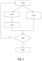
- FIG. 2 a flowchart of a real-time lateral interference detection method according to another example of the present invention is illustratively described in conjunction with FIG. 2 .
- step S200 lateral interference detection begins.
- step S210 the actual steering torque T EPS applied by the EPS at time t is detected by the torque sensor.
- step S220 the vehicle speed v at time t+ ⁇ t is obtained by the vehicle's speed sensor, and the actual yaw rate W s at time t+ ⁇ t is detected by the yaw rate sensor.
- step S230 the estimated steering torque T EXP at time t applied by the EPS is calculated through interpolation using the vehicle speed v at time t+ ⁇ t and the actual yaw rate W s at time t+ ⁇ t.
- the reason for calculating the estimated steering torque T EXP at time t using the vehicle speed v at time t+ ⁇ t and the actual yaw rate W s at time t+ ⁇ t through interpolation is to account for the time delay ⁇ t between the steering torque applied by the EPS and the vehicle's yaw rate.
- step S240 the estimated steering torque T EXP at time t calculated in step S230 is compared with the actual steering torque T EPS at time t detected in step S210. If the absolute value of the difference between the actual steering torque T EPS and the estimated steering torque T EXP is less than the threshold T th , the process returns to step S200. If the absolute value of the difference between the actual steering torque T EPS and the estimated steering torque T EXP is greater than the threshold T th , the process advances to step S250.
- step S250 it is determined that the lateral interference experienced by the vehicle has reached a level requiring the driver to take over vehicle control, and preferably, a warning signal is issued.
- the warning signal includes voice signals, steering wheel vibrations, cursor flashing on the display, etc.
- the vehicle may take measures such as automatic deceleration or automatic braking to minimize the risk of an accident.
- ⁇ t when the vehicle speed is higher than a predetermined value and the acceleration or deceleration is lower than a preset value, the effect of the time delay ⁇ t can be ignored, i.e., ⁇ t can be considered equal to 0.
- step S130 can be performed in parallel with step S110, and when ignoring the effect of the time delay ⁇ t, i.e., assuming ⁇ t equals 0, step S130 can be performed simultaneously with step S110.
- steps S210 and S220 in the second example can also be performed in parallel.
Landscapes
- Engineering & Computer Science (AREA)
- Automation & Control Theory (AREA)
- Transportation (AREA)
- Mechanical Engineering (AREA)
- Human Computer Interaction (AREA)
- Physics & Mathematics (AREA)
- Mathematical Physics (AREA)
- Steering Control In Accordance With Driving Conditions (AREA)
- Chemical & Material Sciences (AREA)
- Combustion & Propulsion (AREA)
- Control Of Driving Devices And Active Controlling Of Vehicle (AREA)
- Traffic Control Systems (AREA)
Abstract
calculating the estimated steering torque TEXP applied by the EPS at time t based on the vehicle speed v at time t+Δt, the actual yaw rate Ws at time t+Δt, and the relationship between the desired yaw rate and the vehicle speed and the steering torque applied by the EPS; and
comparing the estimated steering torque TEXP with the actual steering torque TEPS, and if the absolute value of the difference between the estimated steering torque TEXP and the actual steering torque TEPS is greater than a threshold Tth, determining that the lateral interference experienced by the vehicle has reached a preset level requiring the driver to take over vehicle control.
Description
- This application relates to a method for real-time lateral interference detection for vehicles equipped with driver assistance systems. Specifically, this application involves a method for real-time lateral interference detection in vehicles equipped with Advanced Driver Assistance Systems (ADAS). The present disclosure also involves an apparatus for performing the method of real-time lateral interference detection in vehicles with driver assistance systems, as well as a vehicle comprising such an apparatus. Additionally, the present disclosure involves a computer-readable storage medium containing a computer program that implements the method of real-time lateral interference detection in vehicles with driver assistance systems.
- With the advancement of science and technology, the driver assistance/autonomous driving functions of vehicles are becoming increasingly powerful. Currently, the automotive industry generally classifies autonomous driving functions into levels L1-L5. For the currently achievable levels L2, L3, and L4, the vehicle's autonomous driving system needs to control the vehicle's lateral dynamic motion. However, if the driving conditions are extremely adverse, the autonomous driving system may not be able to control the vehicle's lateral dynamic motion, and at this point, the driver needs to take over control of the vehicle.
- Specifically, during the driver assistance/autonomous driving (DA/AD) period of the autonomous driving system, there may be significant lateral interference with the vehicle's lateral control, such as poor road conditions or strong crosswinds. In such cases, if the driver does not intervene, the vehicle may be significantly affected and deviate from the lane, posing potential dangers.
- Currently, there are no means to detect the lateral interference experienced by the vehicle. Weather forecasts are considered the only method to detect crosswinds. However, this method is very crude and cannot guarantee accuracy and reliability. Moreover, crosswinds are just one of the factors that can cause lateral interference. Other factors, such as poor road conditions during rain or snow, can also cause lateral interference. These lateral interferences severely affect the usability of the autonomous driving system.
- Although existing lane departure monitoring can somewhat prevent danger, once an alert is issued due to lane departure, it usually indicates a severe incident, and the vehicle will rapidly deviate from the lane. If the driver cannot take over control of the vehicle in time, it is highly likely that a dangerous situation will occur. Therefore, detecting the lateral interference experienced by the vehicle as early as possible before it deviates from the lane can better prevent danger.
- Given the aforementioned issues, the present disclosure aims to provide a method and apparatus for lateral interference detection in a vehicle equipped with a driver assistance system. The present disclosure is intended to offer relatively accurate and reliable information regarding whether the vehicle is experiencing lateral interference to the autonomous driving system, thereby promptly alerting the driver to take over control of the vehicle, and thus better avoiding potential hazards.
- According to one aspect of the present disclosure, a method for real-time lateral interference detection in a vehicle equipped with a driver assistance system is provided, the method comprising pre-calibrating a desired yaw rate induced by a steering torque applied by the vehicle's Electric Power Steering (EPS) at different vehicle speeds to obtain the relationship between the desired yaw rate and the vehicle speed and the steering torque applied by the EPS, and the method at least comprising the following steps:
- obtaining the vehicle speed v at time t and the steering torque TEPS applied by the EPS at time t;
- calculating the estimated yaw rate WEPS of the vehicle at time t based on the obtained vehicle speed v at time t, the steering torque TEPS at time t, and the relationship between the desired yaw rate and the vehicle speed and the steering torque applied by the EPS;
- obtaining the actual yaw rate Ws of the vehicle at time t+Δt, where Δt represents a preset time delay for the yaw rate to be generated after the EPS applies the torque;
- comparing the estimated yaw rate WEPS with the actual yaw rate Ws, and if the absolute value of the difference between the estimated yaw rate WEPS and the actual yaw rate Ws is greater than a threshold Wth, determining that the lateral interference experienced by the vehicle has reached a preset level requiring the driver to take over vehicle control.
- According to another aspect of the present disclosure, a method for real-time lateral interference detection in a vehicle equipped with a driver assistance system is provided, the method comprising pre-calibrating a desired yaw rate induced by a steering torque applied by the vehicle's Electric Power Steering (EPS) at different vehicle speeds to obtain the relationship between the desired yaw rate and the vehicle speed and the steering torque applied by the EPS, and the method at least comprising the following steps:
- obtaining the actual steering torque TEPS applied by the EPS at time t;
- obtaining the vehicle speed v at time t+Δt and the actual yaw rate Ws at time t+Δt, where Δt represents a preset time delay for the yaw rate to be generated after the EPS applies the torque;
- calculating the estimated steering torque TEXP applied by the EPS at time t based on the vehicle speed v at time t+Δt, the actual yaw rate Ws at time t+Δt, and the relationship between the desired yaw rate and the vehicle speed and the steering torque applied by the EPS; and
- comparing the estimated steering torque TEXP with the actual steering torque TEPS, and if the absolute value of the difference between the estimated steering torque TEXP and the actual steering torque TEPS is greater than a threshold Tth, determining that the lateral interference experienced by the vehicle has reached a preset level requiring the driver to take over vehicle control.
- According to another aspect of the present disclosure, an apparatus for real-time lateral interference detection in a vehicle equipped with a driver assistance system is provided, comprising:
- a storage module configured to pre-store the relationship between the vehicle speed and a steering torque applied by the Electric Power Steering (EPS) and the desired yaw rate induced by the steering torque;
- an obtaining module configured to obtain the vehicle speed v at time t, the steering torque TEPS applied by the EPS at time t, and the actual yaw rate Ws of the vehicle at time t+Δt, where Δt represents a preset time delay for the yaw rate to be generated after the EPS applies the torque;
- a calculating module configured to calculate the estimated yaw rate WEPS of the vehicle at time t based on the obtained vehicle speed v at time t, the steering torque TEPS at time t, and the relationship between the desired yaw rate and the vehicle speed and the steering torque applied by the EPS;
- a decision module configured to compare the estimated yaw rate WEPS with the actual yaw rate Ws, and if the absolute value of the difference between the estimated yaw rate WEPS and the actual yaw rate Ws is greater than a threshold Wth, determining that the lateral interference experienced by the vehicle has reached a preset level requiring the driver to take over vehicle control.
- According to another aspect of the present disclosure, an apparatus for real-time lateral interference detection in a vehicle equipped with a driver assistance system is provided, comprising:
- a storage module configured to pre-store the relationship between the vehicle speed and a steering torque applied by the Electric Power Steering (EPS) and the desired yaw rate induced by the steering torque;
- an obtaining module configured to obtain the actual steering torque TEPS applied by the EPS at time t, the vehicle speed v at time t+Δt, and the actual yaw rate Ws at time t+Δt, where Δt represents a preset time delay for the yaw rate to be generated after the EPS applies the torque;
- a calculating module configured to calculate the estimated steering torque TEXP applied by the EPS at time t based on the vehicle speed v at time t+Δt, the actual yaw rate Ws at time t+Δt, and the relationship between the desired yaw rate and the vehicle speed and the steering torque applied by the EPS; and
- a decision module configured to compare the estimated steering torque TEXP with the actual steering torque TEPS, and if the absolute value of the difference between the estimated steering torque TEXP and the actual steering torque TEPS is greater than a threshold Tth, determine that the lateral interference experienced by the vehicle has reached a preset level requiring the driver to take over vehicle control.
- According to another aspect of the present disclosure, a computer-readable storage medium is provided, on which a computer program is stored. When the computer program is executed by a processor, it implements a method for real-time lateral interference detection for a vehicle equipped with a driver assistance system according to the present disclosure.
- According to another aspect of the present disclosure, a vehicle is provided, which includes an apparatus for real-time lateral interference detection for a vehicle equipped with a driver assistance system according to the present disclosure.
- The lateral interference detection method and apparatus of the present disclosure can provide relatively accurate and reliable information regarding whether the vehicle is experiencing lateral interference to an autonomous driving system. Furthermore, the technical solution of the present disclosure is based on existing sensors in the ADAS system and generally does not require the additional installation of other components. Therefore, the present disclosure can achieve lateral interference detection for an autonomous driving system at a relatively low cost.
- In the following, examples of the present disclosure will be described in more detail with reference to the accompanying drawings, wherein:
-
FIG. 1 exemplarily illustrates a flowchart of a real-time lateral interference detection method according to one example of the present disclosure. -
FIG. 2 exemplarily illustrates a flowchart of a real-time lateral interference detection method according to another example of the present disclosure. - Other objectives and features of the examples herein will become apparent from the detailed description provided below in conjunction with the accompanying drawings. However, it should be understood that the drawings are designed merely for illustrative purposes and are not intended to limit the scope of the present disclosure.
- The vehicle in the present disclosure is equipped with a driver assistance system, particularly an Advanced Driver Assistance System (ADAS). The vehicle is at least equipped with a yaw rate sensor, a steering torque sensor, and a vehicle speed sensor, and these sensors can be located at any suitable position within the vehicle. Although not mentioned herein, other sensors besides the aforementioned ones may also be possible if needed.
- The principles of the real-time lateral interference detection method of the present disclosure are described in detail below.
- 1) In the absence of lateral interference, the vehicle's yaw rate (WEPS) induced by Electric Power Steering (EPS) is a function of the vehicle speed v and the steering torque TEPS applied by the EPS, as represented by the following formula (1):

- v represents the vehicle speed;
- TEPS represents the steering torque applied by the EPS.
- 2) In the presence of lateral interference, there can be two scenarios:
- 2.1) The vehicle experiences lateral interference without the EPS applying steering torque: In this case, the vehicle only has a yaw rate induced by the lateral interference and no steering torque applied by the EPS.
In such a case, in the prior art, the EPS is only activated to apply active steering torque to the vehicle when the vehicle deviates from the lane and the ADAS system attempts to control the vehicle to return it to the lane. - 2.2) The vehicle experiences lateral interference while the EPS is applying steering torque: In this case, the vehicle's yaw rate includes both the yaw rate induced by the lateral interference and the yaw rate induced by the steering torque applied by the EPS.
- 2.1) The vehicle experiences lateral interference without the EPS applying steering torque: In this case, the vehicle only has a yaw rate induced by the lateral interference and no steering torque applied by the EPS.
- The real-time lateral interference detection scheme of the present disclosure is described in detail below.
a) The desired yaw rate induced by the steering torque applied by the EPS at different vehicle speeds is pre-calibrated. The calibration process is preferably conducted during the vehicle's R&D phase or before the vehicle leaves the factory. The desired calibration results can be tabulated to show the relationship between the desired yaw rate, vehicle speed, and the steering torque applied by the EPS. An exemplary table is as follows:Table 1 Yaw Rate Calibration Table V1 V2 V3 ...... Vn T1 W11 W12 W13 ...... W1n T2 W21 W22 W23 ...... W2n ...... Tm Wm1 Wm2 Wm3 ...... Wmn
b) During vehicle operation: - i) The torque applied by the EPS TEPS is detected by the torque sensor of the EPS;
- ii) The vehicle speed v is obtained by the vehicle speed sensor.
- iii) The actual yaw rate of the vehicle Ws is detected by the yaw rate sensor.
- Δt represents the time delay, which can be preset based on experience or experiments.
- In other words, if the absolute value of the estimated yaw rate WEPS calculated from the torque TEPS detected by the torque sensor of the EPS at time t and the vehicle speed v obtained by the vehicle speed sensor at time t minus the actual yaw rate Ws detected by the yaw rate sensor at time t+Δt is greater than the threshold, it can be considered that the lateral interference experienced by the vehicle has reached a level requiring the driver to take over vehicle control.
- i) Based on Table 1, using the vehicle speed v and the actual yaw rate Ws, the estimated steering torque TEXP applied by the EPS is calculated, preferably by interpolation.
- ii) The calculated estimated steering torque TEXP is compared with the actual steering torque TEPS detected by the torque sensor of the EPS. If the following inequality is satisfied, it can be considered that the lateral interference experienced by the vehicle has reached a level requiring the driver to take over vehicle control.


Δ t represents the time delay for the yaw rate to be generated after the EPS applies the torque, which can be preset based on experience or experiments. - In other words, if the absolute value of the estimated torque TEXP calculated from the vehicle speed v obtained by the vehicle speed sensor at time t and the actual yaw rate Ws detected by the yaw rate sensor at time t minus the actual torque TEPS detected by the torque sensor of the EPS at time t-Δt is greater than the threshold, it can be considered that the lateral interference experienced by the vehicle has reached a level requiring the driver to take over vehicle control.
- Of course, in cases where the vehicle speed is relatively high and does not change significantly, the effect of the time delay (Δt) can be ignored. For example, when the vehicle speed is higher than a predetermined value and the acceleration/deceleration is lower than a preset value, the effect of the time delay (Δt) can be ignored. That is, the above formula (5) can be replaced by the following formula.

- The steps of the method according to the present disclosure are illustratively described below with reference to the accompanying drawings.
-
FIG. 1 illustrates a flowchart of a real-time lateral interference detection method according to one example of the present disclosure. - In step S100, lateral interference detection begins.
- In step S110, the actual steering torque TEPS applied by the Electric Power Steering (EPS) at time t is detected by the vehicle's torque sensor, and the vehicle speed vat time t is obtained by the vehicle's speed sensor.
- In step S120, the estimated yaw rate WEPS is calculated using the actual steering torque TEPS at time t, the vehicle speed v at time t, and Table 1 through interpolation.
- In step S130, the actual yaw rate Ws at time t+Δt is detected by the yaw rate sensor.
- In step S140, the estimated yaw rate WEPS calculated in step S120 is compared with the actual yaw rate Ws detected in step S130. If the absolute value of the difference between the estimated yaw rate WEPS and the actual yaw rate Ws is less than the threshold Wth, the process returns to step S100. If the absolute value of the difference between the estimated yaw rate WEPS and the actual yaw rate Ws is greater than the threshold Wth, the process advances to step S150.
- In step S150, it is determined that the lateral interference experienced by the vehicle has reached a level requiring the driver to take over vehicle control, and preferably, a warning signal is issued. Preferably, the warning signal includes voice signals, steering wheel vibrations, cursor flashing on the display, etc. Optionally, if the driver does not take over vehicle control after a certain period of alerting, the vehicle may take measures such as automatic deceleration or automatic braking to minimize the risk of an accident.
- Below, a flowchart of a real-time lateral interference detection method according to another example of the present invention is illustratively described in conjunction with
FIG. 2 . - In step S200, lateral interference detection begins.
- In step S210, the actual steering torque TEPS applied by the EPS at time t is detected by the torque sensor.
- In step S220, the vehicle speed v at time t+Δt is obtained by the vehicle's speed sensor, and the actual yaw rate Ws at time t+Δt is detected by the yaw rate sensor.
- In step S230, the estimated steering torque TEXP at time t applied by the EPS is calculated through interpolation using the vehicle speed v at time t+Δt and the actual yaw rate Ws at time t+Δt. The reason for calculating the estimated steering torque TEXP at time t using the vehicle speed v at time t+Δt and the actual yaw rate Ws at time t+Δt through interpolation is to account for the time delay Δt between the steering torque applied by the EPS and the vehicle's yaw rate.
- In step S240, the estimated steering torque TEXP at time t calculated in step S230 is compared with the actual steering torque TEPS at time t detected in step S210. If the absolute value of the difference between the actual steering torque TEPS and the estimated steering torque TEXP is less than the threshold Tth, the process returns to step S200. If the absolute value of the difference between the actual steering torque TEPS and the estimated steering torque TEXP is greater than the threshold Tth, the process advances to step S250.
- In step S250, it is determined that the lateral interference experienced by the vehicle has reached a level requiring the driver to take over vehicle control, and preferably, a warning signal is issued. Preferably, the warning signal includes voice signals, steering wheel vibrations, cursor flashing on the display, etc. Optionally, if the driver does not take over vehicle control after a certain period of alerting, the vehicle may take measures such as automatic deceleration or automatic braking to minimize the risk of an accident.
- In the above examples, when the vehicle speed is higher than a predetermined value and the acceleration or deceleration is lower than a preset value, the effect of the time delay Δt can be ignored, i.e., Δt can be considered equal to 0.
- Furthermore, the steps of the above method are not necessarily in chronological order. For example, in the first example, step S130 can be performed in parallel with step S110, and when ignoring the effect of the time delay Δt, i.e., assuming Δt equals 0, step S130 can be performed simultaneously with step S110. Similarly, steps S210 and S220 in the second example can also be performed in parallel.
- Therefore, although the features of the examples have been shown and described herein, it is understood that those skilled in the art can make various omissions, substitutions, and changes in the form and details of the methods shown and their operations, and the sequence of the steps of the above methods is merely exemplary. Adjustments to the steps of the method of the present invention are possible as long as the functions of the present invention can be achieved. For example, all combinations of method steps that perform substantially the same function in substantially the same way to achieve the same result are equivalent.
c) The calculated estimated yaw rate WEPS is compared with the actual yaw rate Ws detected by the yaw rate sensor. If the difference between the two exceeds the threshold Wth, it can be considered that the lateral interference experienced by the vehicle has reached a level requiring the driver to take over vehicle control. The above comparison can be represented by the following inequality:

d) When the EPS applies steering torque, the corresponding yaw rate WEPS may occur after a very short time. Therefore, when making the above comparison, it is preferable to consider the time delay (Δt), so the above inequality (2) is adjusted to the following inequality:

Claims (10)
- A method for real-time lateral interference detection in a vehicle equipped with a driver assistance system, the method comprising pre-calibrating a desired yaw rate induced by a steering torque applied by the vehicle's Electric Power Steering (EPS) at different vehicle speeds to obtain the relationship between the desired yaw rate and the vehicle speed and the steering torque applied by the EPS, and the method at least comprising the following steps:obtaining the vehicle speed v at time t and the steering torque TEPS applied by the EPS at time t;calculating the estimated yaw rate WEPS of the vehicle at time t based on the obtained vehicle speed v at time t, the steering torque TEPS at time t, and the relationship between the desired yaw rate and the vehicle speed and the steering torque applied by the EPS;obtaining the actual yaw rate Ws of the vehicle at time t+Δt, where Δt represents a preset time delay for the yaw rate to be generated after the EPS applies the torque;comparing the estimated yaw rate WEPS with the actual yaw rate Ws, and if the absolute value of the difference between the estimated yaw rate WEPS and the actual yaw rate Ws is greater than a threshold Wth, determining that the lateral interference experienced by the vehicle has reached a preset level requiring the driver to take over vehicle control.
- A method for real-time lateral interference detection in a vehicle equipped with a driver assistance system, the method comprising pre-calibrating a desired yaw rate induced by a steering torque applied by the vehicle's Electric Power Steering (EPS) at different vehicle speeds to obtain the relationship between the desired yaw rate and the vehicle speed and the steering torque applied by the EPS, and the method at least comprising the following steps:obtaining the actual steering torque TEPS applied by the EPS at time t;obtaining the vehicle speed v at time t+Δt and the actual yaw rate Ws at time t+Δt, where Δt represents a preset time delay for the yaw rate to be generated after the EPS applies the torque;calculating the estimated steering torque TEXP applied by the EPS at time t based on the vehicle speed v at time t+Δt, the actual yaw rate Ws at time t+Δt, and the relationship between the desired yaw rate and the vehicle speed and the steering torque applied by the EPS; andcomparing the estimated steering torque TEXP with the actual steering torque TEPS, and if the absolute value of the difference between the estimated steering torque TEXP and the actual steering torque TEPS is greater than a threshold Tth, determining that the lateral interference experienced by the vehicle has reached a preset level requiring the driver to take over vehicle control.
- The method according to Claim 1 or 2, characterized in that: the relationship between the desired yaw rate and the vehicle speed and the steering torque applied by the EPS is tabulated.
- The method according to Claim 1 or 2, characterized in that: the calculation is performed using an interpolation method.
- The method according to Claim 1 or 2, characterized in that: when the vehicle speed is higher than a predetermined value and the acceleration or deceleration is lower than a preset value, Δt equals 0.
- The method according to Claim 1 or 2, characterized in that: the driver is alerted to take over vehicle control through voice signals, steering wheel vibrations, or cursor flashing on a display.
- The method according to Claim 6, characterized in that: if the driver does not take over vehicle control within a preset time after being alerted, the vehicle can perform automatic deceleration or automatic braking.
- An apparatus for real-time lateral interference detection in a vehicle equipped with a driver assistance system, comprising:a storage module configured to pre-store the relationship between the vehicle speed and a steering torque applied by the Electric Power Steering (EPS) and the desired yaw rate induced by the steering torque;an obtaining module configured to obtain the vehicle speed v at time t, the steering torque TEPS applied by the EPS at time t, and the actual yaw rate Ws of the vehicle at time t+Δt, where Δt represents a preset time delay for the yaw rate to be generated after the EPS applies the torque;a calculating module configured to calculate the estimated yaw rate WEPS of the vehicle at time t based on the obtained vehicle speed v at time t, the steering torque TEPS at time t, and the relationship between the desired yaw rate and the vehicle speed and the steering torque applied by the EPS;a decision module configured to compare the estimated yaw rate WEPS with the actual yaw rate Ws, and if the absolute value of the difference between the estimated yaw rate WEPS and the actual yaw rate Ws is greater than a threshold Wth, determining that the lateral interference experienced by the vehicle has reached a preset level requiring the driver to take over vehicle control.
- An apparatus for real-time lateral interference detection in a vehicle equipped with a driver assistance system, comprising:a storage module configured to pre-store the relationship between the vehicle speed and a steering torque applied by the Electric Power Steering (EPS) and the desired yaw rate induced by the steering torque;an obtaining module configured to obtain the actual steering torque TEPS applied by the EPS at time t, the vehicle speed v at time t+Δt, and the actual yaw rate Ws at time t+Δt, where Δt represents a preset time delay for the yaw rate to be generated after the EPS applies the torque;a calculating module configured to calculate the estimated steering torque TEXP applied by the EPS at time t based on the vehicle speed v at time t+Δt, the actual yaw rate Ws at time t+Δt, and the relationship between the desired yaw rate and the vehicle speed and the steering torque applied by the EPS; anda decision module configured to compare the estimated steering torque TEXP with the actual steering torque TEPS, and if the absolute value of the difference between the estimated steering torque TEXP and the actual steering torque TEPS is greater than a threshold Tth, determine that the lateral interference experienced by the vehicle has reached a preset level requiring the driver to take over vehicle control.
- A computer-readable storage medium storing a computer program, which when executed by a processor, implements the method according to any one of Claims 1-7.
Applications Claiming Priority (1)
| Application Number | Priority Date | Filing Date | Title |
|---|---|---|---|
| CN202311305112.3A CN119796209A (en) | 2023-10-10 | 2023-10-10 | Method and apparatus for real-time lateral interference detection of a vehicle |
Publications (1)
| Publication Number | Publication Date |
|---|---|
| EP4538139A1 true EP4538139A1 (en) | 2025-04-16 |
Family
ID=92801534
Family Applications (1)
| Application Number | Title | Priority Date | Filing Date |
|---|---|---|---|
| EP24200478.6A Pending EP4538139A1 (en) | 2023-10-10 | 2024-09-16 | Method and apparatus for real-time lateral interference detection for vehicless, computer-readable storage medium |
Country Status (4)
| Country | Link |
|---|---|
| US (1) | US20250115252A1 (en) |
| EP (1) | EP4538139A1 (en) |
| JP (1) | JP2025066093A (en) |
| CN (1) | CN119796209A (en) |
Citations (3)
| Publication number | Priority date | Publication date | Assignee | Title |
|---|---|---|---|---|
| US20200391726A1 (en) * | 2019-06-14 | 2020-12-17 | Baidu Online Network Technology (Beijing) Co., Ltd. | Control method and apparatus for autonomous vehicle, computer device, and storage medium |
| US20210197812A1 (en) * | 2019-12-27 | 2021-07-01 | Honda Motor Co., Ltd. | Vehicle control apparatus, vehicle, and vehicle control method |
| US20220410880A1 (en) * | 2021-06-29 | 2022-12-29 | Honda Motor Co., Ltd. | Driving assistance device, monitoring device, driving assistance method, and storage medium |
Family Cites Families (1)
| Publication number | Priority date | Publication date | Assignee | Title |
|---|---|---|---|---|
| JP7369045B2 (en) * | 2020-01-24 | 2023-10-25 | 日立Astemo株式会社 | Steering control device |
-
2023
- 2023-10-10 CN CN202311305112.3A patent/CN119796209A/en active Pending
-
2024
- 2024-09-16 EP EP24200478.6A patent/EP4538139A1/en active Pending
- 2024-09-30 US US18/901,190 patent/US20250115252A1/en active Pending
- 2024-10-09 JP JP2024177137A patent/JP2025066093A/en active Pending
Patent Citations (3)
| Publication number | Priority date | Publication date | Assignee | Title |
|---|---|---|---|---|
| US20200391726A1 (en) * | 2019-06-14 | 2020-12-17 | Baidu Online Network Technology (Beijing) Co., Ltd. | Control method and apparatus for autonomous vehicle, computer device, and storage medium |
| US20210197812A1 (en) * | 2019-12-27 | 2021-07-01 | Honda Motor Co., Ltd. | Vehicle control apparatus, vehicle, and vehicle control method |
| US20220410880A1 (en) * | 2021-06-29 | 2022-12-29 | Honda Motor Co., Ltd. | Driving assistance device, monitoring device, driving assistance method, and storage medium |
Also Published As
| Publication number | Publication date |
|---|---|
| CN119796209A (en) | 2025-04-11 |
| US20250115252A1 (en) | 2025-04-10 |
| JP2025066093A (en) | 2025-04-22 |
Similar Documents
| Publication | Publication Date | Title |
|---|---|---|
| KR101665451B1 (en) | Method and apparatus for deciding emergency braking of vehicle | |
| US10435063B2 (en) | System and method for determining vehicle steering misalignment | |
| US10378890B2 (en) | Apparatus and method for determining wheel alignment change of vehicle | |
| US10933883B2 (en) | Driving control apparatus and method for vehicle | |
| US10940867B2 (en) | Substitution of sensor measurement data | |
| US9569968B2 (en) | Method and device for the automated braking and steering of a vehicle | |
| US10150472B2 (en) | Method for automatically assessing a risk of collision between a vehicle and an object | |
| US20200290618A1 (en) | Adaptive control of automated lane change in vehicle | |
| US20130124053A1 (en) | Vehicle safety system and method with split active/passive processing | |
| US20200148260A1 (en) | Lane changing system and lane changing method | |
| US10336324B2 (en) | Calculation of the time to collision for a vehicle | |
| JP2008290600A (en) | Travel control device of vehicle | |
| US20240317267A1 (en) | A method for controlling a maximum allowed speed of an autonomous vehicle | |
| US20200094822A1 (en) | Determination of a Control Signal for an In-Part-Autonomous Vehicle | |
| CN112721924A (en) | Automatic emergency braking system combining with driver state monitoring | |
| US10220846B2 (en) | Method and device for operating a vehicle | |
| EP4538139A1 (en) | Method and apparatus for real-time lateral interference detection for vehicless, computer-readable storage medium | |
| US20170072996A1 (en) | Apparatus and method for controlling electric power steering system | |
| KR102031619B1 (en) | Apparatus And Method For Steering Control Of Autonomous Vehicle | |
| KR102286027B1 (en) | Vehicle control apparatus and vehicle control method | |
| KR20230023080A (en) | Power steering apparatus and method for autonomous vehicle | |
| JP5194832B2 (en) | Vehicle collision safety control device | |
| US11400926B2 (en) | Adaptive object in-path detection model for automated or semi-automated vehicle operation | |
| US10189455B2 (en) | Method for performing a braking maneuver using a vehicle braking assistant | |
| KR102557831B1 (en) | Apparatus and method for controlling driving of vehicle |
Legal Events
| Date | Code | Title | Description |
|---|---|---|---|
| PUAI | Public reference made under article 153(3) epc to a published international application that has entered the european phase |
Free format text: ORIGINAL CODE: 0009012 |
|
| STAA | Information on the status of an ep patent application or granted ep patent |
Free format text: STATUS: THE APPLICATION HAS BEEN PUBLISHED |
|
| AK | Designated contracting states |
Kind code of ref document: A1 Designated state(s): AL AT BE BG CH CY CZ DE DK EE ES FI FR GB GR HR HU IE IS IT LI LT LU LV MC ME MK MT NL NO PL PT RO RS SE SI SK SM TR |
|
| STAA | Information on the status of an ep patent application or granted ep patent |
Free format text: STATUS: REQUEST FOR EXAMINATION WAS MADE |
|
| 17P | Request for examination filed |
Effective date: 20251016 |
|
| GRAP | Despatch of communication of intention to grant a patent |
Free format text: ORIGINAL CODE: EPIDOSNIGR1 |
|
| STAA | Information on the status of an ep patent application or granted ep patent |
Free format text: STATUS: GRANT OF PATENT IS INTENDED |
|
| INTG | Intention to grant announced |
Effective date: 20260203 |
|
| RIC1 | Information provided on ipc code assigned before grant |
Ipc: B60W 50/14 20200101AFI20260126BHEP Ipc: B60W 60/00 20200101ALI20260126BHEP |