EP4538133A1 - Signal processing device of vehicle and communication device for vehicle communication device including same - Google Patents
Signal processing device of vehicle and communication device for vehicle communication device including same Download PDFInfo
- Publication number
- EP4538133A1 EP4538133A1 EP23819947.5A EP23819947A EP4538133A1 EP 4538133 A1 EP4538133 A1 EP 4538133A1 EP 23819947 A EP23819947 A EP 23819947A EP 4538133 A1 EP4538133 A1 EP 4538133A1
- Authority
- EP
- European Patent Office
- Prior art keywords
- signal processing
- worker node
- service
- processing device
- processor
- Prior art date
- Legal status (The legal status is an assumption and is not a legal conclusion. Google has not performed a legal analysis and makes no representation as to the accuracy of the status listed.)
- Pending
Links
Images
















Classifications
-
- H—ELECTRICITY
- H04—ELECTRIC COMMUNICATION TECHNIQUE
- H04L—TRANSMISSION OF DIGITAL INFORMATION, e.g. TELEGRAPHIC COMMUNICATION
- H04L41/00—Arrangements for maintenance, administration or management of data switching networks, e.g. of packet switching networks
- H04L41/40—Arrangements for maintenance, administration or management of data switching networks, e.g. of packet switching networks using virtualisation of network functions or resources, e.g. SDN or NFV entities
-
- G—PHYSICS
- G06—COMPUTING OR CALCULATING; COUNTING
- G06F—ELECTRIC DIGITAL DATA PROCESSING
- G06F9/00—Arrangements for program control, e.g. control units
- G06F9/06—Arrangements for program control, e.g. control units using stored programs, i.e. using an internal store of processing equipment to receive or retain programs
- G06F9/44—Arrangements for executing specific programs
- G06F9/455—Emulation; Interpretation; Software simulation, e.g. virtualisation or emulation of application or operating system execution engines
- G06F9/45533—Hypervisors; Virtual machine monitors
- G06F9/45558—Hypervisor-specific management and integration aspects
-
- G—PHYSICS
- G06—COMPUTING OR CALCULATING; COUNTING
- G06F—ELECTRIC DIGITAL DATA PROCESSING
- G06F9/00—Arrangements for program control, e.g. control units
- G06F9/06—Arrangements for program control, e.g. control units using stored programs, i.e. using an internal store of processing equipment to receive or retain programs
- G06F9/44—Arrangements for executing specific programs
- G06F9/455—Emulation; Interpretation; Software simulation, e.g. virtualisation or emulation of application or operating system execution engines
- G06F9/45533—Hypervisors; Virtual machine monitors
-
- G—PHYSICS
- G06—COMPUTING OR CALCULATING; COUNTING
- G06F—ELECTRIC DIGITAL DATA PROCESSING
- G06F9/00—Arrangements for program control, e.g. control units
- G06F9/06—Arrangements for program control, e.g. control units using stored programs, i.e. using an internal store of processing equipment to receive or retain programs
- G06F9/46—Multiprogramming arrangements
- G06F9/54—Interprogram communication
-
- G—PHYSICS
- G06—COMPUTING OR CALCULATING; COUNTING
- G06V—IMAGE OR VIDEO RECOGNITION OR UNDERSTANDING
- G06V20/00—Scenes; Scene-specific elements
- G06V20/50—Context or environment of the image
- G06V20/56—Context or environment of the image exterior to a vehicle by using sensors mounted on the vehicle
- G06V20/588—Recognition of the road, e.g. of lane markings; Recognition of the vehicle driving pattern in relation to the road
-
- G—PHYSICS
- G06—COMPUTING OR CALCULATING; COUNTING
- G06V—IMAGE OR VIDEO RECOGNITION OR UNDERSTANDING
- G06V40/00—Recognition of biometric, human-related or animal-related patterns in image or video data
- G06V40/10—Human or animal bodies, e.g. vehicle occupants or pedestrians; Body parts, e.g. hands
- G06V40/16—Human faces, e.g. facial parts, sketches or expressions
-
- G—PHYSICS
- G08—SIGNALLING
- G08G—TRAFFIC CONTROL SYSTEMS
- G08G1/00—Traffic control systems for road vehicles
- G08G1/01—Detecting movement of traffic to be counted or controlled
- G08G1/0104—Measuring and analyzing of parameters relative to traffic conditions
- G08G1/0137—Measuring and analyzing of parameters relative to traffic conditions for specific applications
-
- H—ELECTRICITY
- H04—ELECTRIC COMMUNICATION TECHNIQUE
- H04L—TRANSMISSION OF DIGITAL INFORMATION, e.g. TELEGRAPHIC COMMUNICATION
- H04L67/00—Network arrangements or protocols for supporting network services or applications
- H04L67/01—Protocols
- H04L67/12—Protocols specially adapted for proprietary or special-purpose networking environments, e.g. medical networks, sensor networks, networks in vehicles or remote metering networks
-
- B—PERFORMING OPERATIONS; TRANSPORTING
- B60—VEHICLES IN GENERAL
- B60W—CONJOINT CONTROL OF VEHICLE SUB-UNITS OF DIFFERENT TYPE OR DIFFERENT FUNCTION; CONTROL SYSTEMS SPECIALLY ADAPTED FOR HYBRID VEHICLES; ROAD VEHICLE DRIVE CONTROL SYSTEMS FOR PURPOSES NOT RELATED TO THE CONTROL OF A PARTICULAR SUB-UNIT
- B60W40/00—Estimation or calculation of non-directly measurable driving parameters for road vehicle drive control systems not related to the control of a particular sub unit, e.g. by using mathematical models
- B60W40/02—Estimation or calculation of non-directly measurable driving parameters for road vehicle drive control systems not related to the control of a particular sub unit, e.g. by using mathematical models related to ambient conditions
-
- G—PHYSICS
- G06—COMPUTING OR CALCULATING; COUNTING
- G06F—ELECTRIC DIGITAL DATA PROCESSING
- G06F9/00—Arrangements for program control, e.g. control units
- G06F9/06—Arrangements for program control, e.g. control units using stored programs, i.e. using an internal store of processing equipment to receive or retain programs
- G06F9/44—Arrangements for executing specific programs
- G06F9/455—Emulation; Interpretation; Software simulation, e.g. virtualisation or emulation of application or operating system execution engines
- G06F9/45533—Hypervisors; Virtual machine monitors
- G06F9/45558—Hypervisor-specific management and integration aspects
- G06F2009/45562—Creating, deleting, cloning virtual machine instances
-
- G—PHYSICS
- G06—COMPUTING OR CALCULATING; COUNTING
- G06F—ELECTRIC DIGITAL DATA PROCESSING
- G06F9/00—Arrangements for program control, e.g. control units
- G06F9/06—Arrangements for program control, e.g. control units using stored programs, i.e. using an internal store of processing equipment to receive or retain programs
- G06F9/44—Arrangements for executing specific programs
- G06F9/455—Emulation; Interpretation; Software simulation, e.g. virtualisation or emulation of application or operating system execution engines
- G06F9/45533—Hypervisors; Virtual machine monitors
- G06F9/45558—Hypervisor-specific management and integration aspects
- G06F2009/45579—I/O management, e.g. providing access to device drivers or storage
-
- G—PHYSICS
- G06—COMPUTING OR CALCULATING; COUNTING
- G06F—ELECTRIC DIGITAL DATA PROCESSING
- G06F9/00—Arrangements for program control, e.g. control units
- G06F9/06—Arrangements for program control, e.g. control units using stored programs, i.e. using an internal store of processing equipment to receive or retain programs
- G06F9/44—Arrangements for executing specific programs
- G06F9/455—Emulation; Interpretation; Software simulation, e.g. virtualisation or emulation of application or operating system execution engines
- G06F9/45533—Hypervisors; Virtual machine monitors
- G06F9/45558—Hypervisor-specific management and integration aspects
- G06F2009/45595—Network integration; Enabling network access in virtual machine instances
-
- H—ELECTRICITY
- H04—ELECTRIC COMMUNICATION TECHNIQUE
- H04L—TRANSMISSION OF DIGITAL INFORMATION, e.g. TELEGRAPHIC COMMUNICATION
- H04L12/00—Data switching networks
- H04L12/28—Data switching networks characterised by path configuration, e.g. LAN [Local Area Networks] or WAN [Wide Area Networks]
- H04L12/40—Bus networks
-
- H—ELECTRICITY
- H04—ELECTRIC COMMUNICATION TECHNIQUE
- H04L—TRANSMISSION OF DIGITAL INFORMATION, e.g. TELEGRAPHIC COMMUNICATION
- H04L12/00—Data switching networks
- H04L12/28—Data switching networks characterised by path configuration, e.g. LAN [Local Area Networks] or WAN [Wide Area Networks]
- H04L12/40—Bus networks
- H04L2012/40267—Bus for use in transportation systems
- H04L2012/40273—Bus for use in transportation systems the transportation system being a vehicle
Definitions
- a vehicle is a machine that allows a user to move in a desired direction.
- a typical example of the vehicle is an automobile.
- a signal processing device for vehicles is mounted in a vehicle for convenience of users using the vehicle.
- Korean Laid-open Patent Publication No. 10-2017-0043002 as related art discloses a method of operating a communication node in a network.
- a vehicle signal processing device capable of efficiently processing a service or application
- a vehicle communication device including the vehicle signal processing device.
- the master node may be configured to transmit a command to at least one worker node based on scheduling, and a container in the worker node is configured to receive the command may be configured to operate based on the command.
- the master node may be configured to selectively duplicate a service or application or perform one of software duplication, hardware duplication, and hybrid duplication, based on a safety level of a service or application, available resources, or a state of the worker node.
- the processor may be configured to select the worker node in one of the plurality of zonal signal processing devices and the worker node in the server, and execute the second service or the second application on the worker node in one of the plurality of zonal signal processing devices and the worker node in the server.
- the processor may be configured to execute a driver monitoring service, which is executed after the vehicle starts, on the worker node in the signal processing device.
- the processor may be configured to execute the lane detection service on the worker node in the plurality of zonal signal processing devices, among the worker node in the plurality of zonal signal processing devices, the worker node in the server, and the worker node in the signal processing device.
- the processor may be configured to execute the lane keeping analysis service for the highway on the worker node in one of the plurality of zonal signal processing devices, among the worker node in the plurality of zonal signal processing devices, the worker node in the server, or the worker node in the signal processing device.
- the master node may be configured to execute an application controller, a node controller, a scheduler, and an orchestration server, wherein the worker node may be configured to execute an orchestration proxy, container runtime, container, and node manager. Accordingly, a service or application may be efficiently processed by the worker node.
- the master node may perform one of software duplication, hardware duplication, and hybrid duplication depending on the service or application. Accordingly, the service or application may be duplicated for processing. As a result, the service or application may be rapidly and stably processed.
- the processor may be configured to execute a driver face detection service or a driver face recognition service, which is executed before a vehicle starts, on the worker node in the plurality of zonal signal processing devices or the worker node in the server. Accordingly, a service or application may be efficiently processed by the worker node.
- the processor may be configured to execute a driver monitoring service, which is executed after the vehicle starts, on the worker node in the signal processing device. Accordingly, a service or application may be efficiently processed by the worker node.
- the processor may be configured to execute a lane detection service, a lane recognition service, a lane keeping analysis service for a general road, or a lane keeping analysis service for a highway. Accordingly, a service or application may be efficiently processed.
- suffixes “module” and “unit” are given only in consideration of ease in preparation of the specification, and do not have or serve different meanings. Accordingly, the suffixes “module” and “unit” may be used interchangeably.
- the vehicle 200 may be further provided therein with a plurality of displays 180a and 180b configured to display images and information.
- the audio video navigation (AVN) display 180b may also be called a center information display.
- the first architecture 300a may correspond to a zone-based architecture.
- the signal processing device 170a may further include an autonomous driving control module ACC, a cockpit control module CPG, etc., in addition to the vehicle communication gateway GWDa.
- the vehicle communication gateway GWDa in the signal processing device 170a may be a High Performance Computing (HPC) gateway.
- HPC High Performance Computing
- FIG. 2C is a diagram illustrating a third architecture of a vehicle communication gateway according to an embodiment of the present disclosure.
- the third architecture is different in that the respective processors ECU are connected directly to the gateway GWDc without being connected to another module.
- the signal processing device 170 includes: a first processor 732a which, based on a first communication scheme, is configured to receive a first message including a vehicle internal sensor signal and perform signal processing on the received first message; and a second processor 732b which, based a second communication scheme, is configured to receive a second message including a communication message received from an external source and perform signal processing on the received second message.
- the second communication scheme may have a faster communication speed or a wider bandwidth than the first communication scheme.
- the second communication scheme may be Ethernet communication
- the first communication scheme may be CAN communication
- the first message may be a CAN message
- the second message may be an Ethernet message.
- the signal processing device 170 further includes: a first memory 320 having an IPC channel; and a second memory 330 storing sensor data including vehicle speed data.
- the signal processing device 170 includes a shared memory 508 that operates for transmitting the first message or the second message between the first processor 732a and the second processor 732b.
- the first processor 732a may further include an interface 319 for receiving the CAN message from external vehicle sensors.
- a first processor core 317o included in the first processor 732a may be configured to execute a plurality of applications or may be configured to execute a first AUTomotive Open System Architecture (AUTOSAR) 312.
- AUTOSAR AUTomotive Open System Architecture
- the first processor 732a implements a message router (not shown), and the message router may convert a frame of the first message, such as the CAN message, into a frame format of the second message, such as the Ethernet message, and may transmit the converted message to the second processor 732b.
- the message router may convert a frame of the first message, such as the CAN message, into a frame format of the second message, such as the Ethernet message, and may transmit the converted message to the second processor 732b.
- the vehicle display apparatus 100 may further include a rear seat entertainment (RSE) display 180c configured to display driving state information, simple navigation information, various kinds of entertainment information, or an image.
- RSE rear seat entertainment
- some of the plurality of displays 180a to 180c may be operated based on a Linux Operating System (OS), and others may be operated based on a Web Operating System (OS).
- OS Linux Operating System
- OS Web Operating System
- the transceiver 120 may wirelessly exchange data with a mobile terminal 800 or a server 900.
- the sensor information may include at least one of vehicle direction information, vehicle position information (global positioning system (GPS) information), vehicle angle information, vehicle speed information, vehicle acceleration information, vehicle inclination information, vehicle forward/backward movement information, battery information, fuel information, tire information, vehicle lamp information, vehicle internal temperature information, and vehicle internal humidity information.
- vehicle position information global positioning system (GPS) information
- GPS global positioning system
- the memory 140 may store data about the hypervisor and first to third virtual machines executed by the hypervisor in the processor 175.
- the audio output device 185 may convert an electrical signal from the signal processing device 170 into an audio signal, and may output the audio signal. To this end, the audio output device 185 may include a speaker.
- the signal processing device 170 may control the overall operation of each device in the vehicle display apparatus 100 or the vehicle 200.
- the first virtual machine (not shown) in the processor 175 may be configured to set the shared memory 508 based on the hypervisor 505 in order to transmit the same data to the second virtual machine (not shown) and the third virtual machine (not shown).
- the signal processing device 170 may process various signals, such as an audio signal, an image signal, and a data signal.
- the signal processing device 170 may be implemented in the form of a system on chip (SOC).
- the second communication gateway 630b may include a telematics control module 620, a head module 622, an Ethernet diagnostic tester 624, an Ethernet switch 636b for exchanging an Ethernet message by Ethernet communication with at least one Ethernet ECU 626, and a second processor 632b for performing signal processing on the Ethernet message received from the Ethernet switch 636b.
- the present disclosure provides a method of reducing latency and performing high-speed data transmission during inter-processor communication, which will be described below with reference to FIG. 7 and subsequent figures.
- the first processor 732a, the second processor 732b, and the shared memory 508 in one signal processing device 170 implemented as a single chip, it is possible to reduce latency and perform high-speed data transmission during the inter-processor communication.
- the second communication scheme has a faster communication speed or a wider bandwidth than the first communication scheme.
- the second communication scheme may be Ethernet communication
- the first communication scheme may be CAN communication
- the first message may be a CAN message
- the second message may be an Ethernet message.
- the second processor 732b or the switch 736b may exchange an Ethernet message by Ethernet communication with the telematics control module 620, the head module 622, the Ethernet diagnostic tester 624, at least one Ethernet ECU 626, and the like.
- the switch 736b may be referred to as an Ethernet switch.
- the first processor 732a may separately process a first message, which is not requested to be subscribed, among the periodically received CAN data or first messages, according to an internal operation without transmitting the message to the second processor 732b.
- the first processor 732a may store the first message in the first cache 735a or may manage the first message. Upon receiving the first message, the first processor 732a may compare the first message with a value stored in the first cache 735a, and if a difference therebetween is greater than or equal to a predetermined value, the first processor 732a may transmit the first message to the second processor 732b through the inter-processor communication using the shared memory 508.
- the first processor 732a may compare the message with a value stored in the first cache 735a, and if the two are not the same, the first processor 732a may transmit the first message to the second processor 732b through the inter-processor communication using the shared memory 508.
- the cache value stored in the second processor 732b may be sent to the Ethernet processor 626 without the inter-processor communication.
- the shared memory 508 may transmit data between the first processor 732a and the second processor 732b through a first queue PTb and a second queue PTa having a higher priority than the first queue PTb.
- the first queue PTb may be a normal priority queue
- the second queue PTa may be a high priority queue.
- the shared memory 508 may transmit the speed data or position information data between the first processor 732a or the second processor 732b through the second queue PTa. Accordingly, real-time transmission of the speed data or the position information data having a high priority may be ensured during the inter-processor communication.
- FIG. 8A is a diagram illustrating an example of a vehicle communication device according to an embodiment of the present disclosure.
- the first virtual machine 820 may be a virtual machine corresponding to quality management (QM) which is the lowest risk level of the ASIL with no mandatory need.
- QM quality management
- the first virtual machine 820 may be configured to execute an operating system 822, a container runtime 824 on the operating system 822, and containers 827 and 829 on the container runtime 824.
- the third virtual machine 840 may be a virtual machine corresponding to ASIL C or ASIL D with the combination of severity, exposure, and controllability values being 9 or 10.
- the third virtual machine 840 may also be executed by a separate core, rather than by the processor 175, which will be described below with reference to FIG. 8B .
- the vehicle communication device 800b of FIG. 8B is similar to the vehicle communication device 800a of FIG. 8A , with a difference being that the signal processing device 170a1 of FIG. 8B is partially different from the signal processing device 170a1 of FIG. 8A .
- the signal processing device 170a may include a processor 175 and a second processor 177.
- the processor 175 in the signal processing device 170a1 executes the hypervisor 505, and executes the first and second virtual machines 820 and 830 on the hypervisor 505 according to the ASIL.
- the first virtual machine 820 may be configured to execute the operating system 822, the container runtime 824 on the operating system 822, and the containers 827 and 829 on the container runtime 824.
- the processor 175 that executes the first and second virtual machines 820 and 830 may correspond to the second processor 732b of FIG. 7
- the second processor 177 that executes the third virtual machine 840 may correspond to the first processor 732a of FIG. 7 .
- a vehicle communication device 800c includes the signal processing devices 170a and 170a2 and the plurality of zonal signal processing devices 170Z1 to 170Z4.
- the plurality of zonal signal processing devices 170Z1 to 170Z4 may be located in the respective zones Z1 to Z4 and may transmit sensor data to the signal processing devices 170a1 and 170a2.
- the signal processing devices 170a1 and 170a2 may receive data by wire from the plurality of zonal signal processing devices 170Z1 to 170Z4 or a communication device 120.
- the signal processing devices 170a1 and 170a2 exchange data with the plurality of zonal signal processing devices 170Z1 to 170Z4 based on wired communication
- the signal processing devices 170a1 and 170a2 exchange data with the server 400 based on wireless communication
- the communication device 120 may exchange data with the server 400 based on wireless communication
- the signal processing devices 170a1 and 170a2 exchange data with the communication device 120 based on wired communication.
- the data received by the signal processing devices 170a1 and 170a2 may include camera data or sensor data.
- the processor 175 transmits data from the Ethernet terminal 910 to virtual network interfaces 922, 932, and 942 in the respective virtual machines 920 to 940 via a physical driver executed in the hypervisor 505.
- the processor 175 in a signal processing device 170ab may receive data by wire through a plurality of Ethernet terminals 910 and 910b, and may transmit the data from the Ethernet terminal 910 to the virtual network interfaces 922 and 932 in the first and second virtual machines 920 and 930 via the physical driver 915 executed in the hypervisor 505 and may transmit the data from a second Ethernet terminal 910b to a physical driver 945 in the third virtual machine 940.
- the processor 175 executes the plurality of virtual machines 920 to 940 on the executed hypervisor 505.
- the processor 175 transmits data from the Ethernet switch 910 to a virtual network interface 922 or virtual drivers 933 and 943 in the respective virtual machines 920 to 940 via a physical driver 916 executed in the hypervisor 505.
- FIG. 9E is a diagram illustrating yet another example of a data transmission scheme of a signal processing device.
- FIG. 9F is a diagram illustrating yet another example of a data transmission scheme of a signal processing device.
- a vehicle communication system 1000 may include a signal processing device 170 in a vehicle, a plurality of zonal signal processing devices 170z, and a signal processing device 170s in an external server 400.
- the plurality of zonal signal processing devices 170z may be configured to execute a virtual machine 870, and may be configured to execute an orchestrator client 875 in the virtual machine 870.
- the virtual machine 870 in the plurality of zonal signal processing devices 170z may operate as a worker node WN.
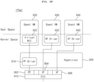
- the processor 175 in the signal processing device 170 executes a hypervisor 505 and executes a plurality of virtual machines 810 to 850 on the hypervisor 505.
- the first virtual machine 810 among the plurality of virtual machines 810 to 860 corresponds to a system service virtual machine
- the second virtual machine 820 among the plurality of virtual machines 810 to 860 corresponds to a virtual machine with a quality management level (e.g., QM)
- the third virtual machine 830 among the plurality of virtual machines 810 to 860 corresponds to a virtual machine with a specific safety level (e.g., ASIL B)
- the fourth virtual machine 840 among the plurality of virtual machines 810 to 860 corresponds to a virtual machine acting as a master node of orchestration
- the fifth virtual machine 850 among the plurality of virtual machines 810 to 860 corresponds to a virtual machine with a specific safety level (e.g., ASIL B)
- the sixth virtual machine 860 among the plurality of virtual machines 810 to 860 corresponds to a higher risk classification level (e.g., ASIL D).
- the virtual machines may be executed based on the safety levels.
- the processor 175 may select at least one of a worker node WN in the plurality of zonal signal processing devices 170z, a worker node WN in a server 400, and a worker node WN in the signal processing device 170, and may be configured to execute a service or application on the selected worker node. Accordingly, the service or application may be efficiently processed.
- FIGS. 12A and 12B are diagrams referred to in the description of a master node and a worker node.
- FIG. 12B illustrates another example of a master node and a worker node.
- the master node MN in a node system 1200b is similar to the master node MN of FIG. 12A , but is different in that the state storage 1207 is omitted.
- FIG. 12A there is a difference between FIG. 12A and FIG. 12B in that the container 1227 and the node manager 1224 are omitted from the worker node WN in FIG. 12B , and an application 1230 is executed in FIG. 12B .
- a load balancer 1234, a plurality of microservices 1236a,1236n, ..., and 1236n, and a messaging interface 1232 may be executed in the application 1230.
- service 1 and service 2 are located at node 1, and service 1 and service 2 are located at node 2.
- service 1 is located at node 1
- service 1' is located at node 2
- service 2 and service 2' are located at node 3.
- the same or similar services are located at node 3 which is the same node, such that software duplication may be performed, and service 1 and service 1' are located at node 1 and node 2 which are different nodes, such that physical duplication of hardware may be performed. Accordingly, stability during hybrid duplication may be ensured.
- the hybrid duplication of FIG. 13C uses a greater number of nodes than the software duplication of FIG. 13A or the hardware duplication of FIG. 13B , but the hybrid duplication is not limited thereto, and various other examples are also possible.
- service 1 runs on node 1 and service 1 runs on node 2, and service 1' runs on node 2.
- the number of nodes used herein is two, which is the same number as FIG. 13A or FIG. 13B .
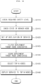
- FIG. 14 is a flowchart illustrating an example of operating a master node.
- the master node MN executed in the processor 175 may check available resources or a state of the worker node WN (S1415).
- the master node MN executed in the processor 175 may filter target node candidates (S1425), may score the target node candidates (S1430), and may select top N worker nodes (S1435) based on the scores.
- the master node MN executed in the processor 175 may select, as top N worker nodes, a plurality of worker nodes WN in the signal processing device 170, or the worker node in the signal processing device 170 and the worker node WN in the zonal signal processing device 170z, or the worker nodes WN in the plurality of zonal signal processing devices 170z, or the worker node WN in the zonal signal processing device 170z and the worker node in the server 400, or a plurality of worker nodes in the server 400.
- the master node MN executed in the processor 175 transmits data for executing a service or application to the selected worker node (S1440). Accordingly, the service or application may be efficiently processed by the worker node WN.
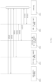
- a manager 1501 in the master node MN transmits a request for node information to a worker node 1503 in the signal processing device 170 (S1510), and receives node information from the worker node 1503 in the signal processing device 170 (S1512).
- the node information of the worker node 1507 in the zonal signal processing device 170z may include a safety level at 0 points, a device level at 2 points, and a performance level at 2 points.
- the manager 1501 in the master node MN transmits a request for node information to a worker node 1509 in the server 400 (S1522), and receives node information from the worker node 1509 in the server 400 (S1524).
- the node information of the worker node 1509 in the server 400 may include a safety level at 0 points, a device level at 0 points, and a performance level at 2 points.
- the processor 175 in the signal processing device 170 may be configured to execute a driver face detection service (S1610) and a driver face recognition service (S1615), based on camera data received from the plurality of zonal signal processing devices 170z.
- S1610 driver face detection service
- S1615 driver face recognition service
- the processor 175 may be configured to execute the driver monitoring service, which is executed after the vehicle starts, on the worker node WN in the signal processing device 170. Accordingly, the service or application may be efficiently processed by the worker node WN.
- the worker node 1704 on which the driver face detection service is executed, executes the driver face detection service based on the received result data (S1718).
- the worker node 1706 on which the driver eye tracking service is executed, may be configured to perform software duplication when the eye tracking service is executed (S1724). Accordingly, the service may be stably executed.
- the worker node 1706 on which the driver eye tracking service is executed, may transmit result data to the worker node 1708 on which the engine or audio service is executed (S1730).
- the worker node 1720 on which the driver face detection service is executed, may be configured to execute the service based on the result data (S1738).
- the worker node 1706 on which the driver eye tracking service is executed, also executes the service on the worker node 1720 which is another worker node, thereby duplicating hardware. Accordingly, the service may be stably executed.
- the processor 175 may select at least one of the worker node WN in the plurality of zonal signal processing devices 170z, the worker node WN in the server 400, and the worker node WN in the signal processing device 170, based on a safety level of a service or application to be executed.
- the processor 175 may select the worker node WN in one of the plurality of zonal signal processing devices 170z and the worker node WN in the server 400, and may be configured to execute the second service or the second application on the worker node WN in one of the plurality of zonal signal processing devices 170z and the worker node WN in the server 400. Accordingly, the service or application may be efficiently processed by the worker node WN.
- the processor 175 may be configured to execute the service or application on the worker node WN in the signal processing device 170 among the worker node WN in the plurality of zonal signal processing devices 170z, the worker node WN in the server 400, and the worker node WN in the signal processing device 170. Accordingly, the service or application may be efficiently processed by the worker node WN.
- the processor 175 may be configured to execute a service or application on the worker node WN in the signal processing device 170, based on software duplication, hardware duplication, or hybrid duplication. Accordingly, the service or application may be duplicated for processing. As a result, the service or application may be rapidly and stably processed.
- FIGS. 18A to 18E are diagrams illustrating an example of selecting a plurality of worker nodes.
- FIG. 18A is a diagram illustrating a plurality of nodes.
- node 1 1810 is a first worker node in the zonal signal processing device 170z
- node 2 1820 is a second worker node in the zonal signal processing device 170z
- node 3 1830 is a worker node in the signal processing device 170
- node 4 1840 is a worker node in the server 400.
- Node 1 1810 may be a worker node corresponding to QM or ASIL B.
- Node 2 1820 and Node 4 1840 may be worker nodes corresponding to QM.
- the audio device 185 and the camera device 195 may be connected to node 2 1820.
- the master node MN executed in the processor 175 of the signal processing device 170 may select node 4 1840 and node 2 1820 in which face data is present, as a safety level of the driver face recognition service is the first level corresponding to QM, and may be configured to execute the drive face recognition service on node 4 1840 and node 2 1820.
- FIG. 18D is a diagram illustrating an example of executing an eye tracking service, which is a driver monitoring service after a vehicle starts, on node 3 1830.
- the eye tracking service may be executed on each of a plurality of worker nodes in the signal processing device 170. Accordingly, the service may be stably and rapidly executed.
- FIG. 18E is a diagram illustrating an example of executing an eye tracking service, which is a driver monitoring service after a vehicle starts, on node 3 1830 and node 1 1810.
- hardware duplication may be performed by executing the eye tracking service in each of different signal processing devices. Accordingly, the service may be stably and rapidly executed.
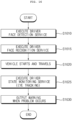
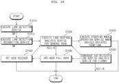
- FIG. 19 is a flowchart illustrating another example of an operation method of executing a service or application.
- the processor 175 in the signal processing device 170 may be configured to execute a lane detection service (S1910) and a lane recognition service (S1915) based on camera data received from the plurality of zonal signal processing device 170z.
- the processor 175 in the signal processing device 170 executes a lane keeping analysis service for a general road (S1920), and the processor 175 may be configured to execute a steering wheel operation service (S1925) when the vehicle deviates from the lane.
- the processor 175 in the signal processing device 170 may recover the node in the signal processing device 170 or may be configured to execute a lane keeping analysis service for a highway (S1935).
- FIG. 20 is a diagram referred to in the description of FIG. 19 .
- the camera device 195 transmits camera data to a worker node 2002 on which a lane detection service is executed (S2010), and the worker node 2002, on which the lane detection service is executed, executes the lane detection service based on the camera data (S2012).
- the worker node 2008 on which the steering wheel operation service is executed, may be configured to execute the steering wheel operation service when a problem occurs in lane keeping (S2024).
- the worker node 2006 on which the lane keeping analysis service is executed, also executes the service on the worker node 2002 which is another worker node, thereby duplicating hardware. Accordingly, the service may be stably executed.
- the worker node 2008 on which the steering wheel operation service is executed may be configured to execute the steering wheel operation service when a problem occurs in lane keeping (S2038). Accordingly, the service may be stably provided.
- the processor 175 may be configured to execute the lane detection service on the worker node WN in the plurality of zonal signal processing devices 170z among the worker node WN in the plurality of zonal signal processing devices 170z, the worker node WN in the server 400, and the worker node WN in the signal processing device 170. Accordingly, a service or application may be efficiently processed by the worker node WN.
- the processor 175 may be configured to execute the lane recognition service on the worker node WN in any one zonal signal processing device 170z and the worker node WN in the server 400 among the worker node WN in the plurality of zonal signal processing devices 170z, the worker node WN in the server 400, and the worker node WN in the signal processing device 170. Accordingly, a service or application may be efficiently processed by the worker node WN.
- FIG. 21A is a diagram illustrating a plurality of nodes.
- Node 3 2130 may be a worker node corresponding to ASIL B.
- FIG. 21D is a diagram illustrating an example in which a lane keeping analysis service for a general road is executed on node 3 2130 and node 4 2140.
- the master node MN executed in the processor 175 of the signal processing device 170 may be configured to execute the lane keeping analysis service for the general road on node 3 2130 and node 4 2140.
- FIG. 21E is a diagram illustrating an example in which the lane keeping analysis service for the general road, which is to be executed on node 3 2130, is not executed.
- the master node MN executed in the processor 175 of the signal processing device 170 may be configured to execute the lane keeping analysis service for the highway on node 4 2140 in consideration of the condition of node 3 2130.
- the master node MN executed in the processor 175 of the signal processing device 170 may be configured to perform software duplication on node 4 2140 as illustrated herein.
- the processor 175 in the signal processing device 170 may be configured to terminate the lane keeping analysis service for the highway.
Landscapes
- Engineering & Computer Science (AREA)
- Software Systems (AREA)
- Theoretical Computer Science (AREA)
- Physics & Mathematics (AREA)
- General Physics & Mathematics (AREA)
- General Engineering & Computer Science (AREA)
- Computer Networks & Wireless Communication (AREA)
- Signal Processing (AREA)
- General Health & Medical Sciences (AREA)
- Health & Medical Sciences (AREA)
- Multimedia (AREA)
- Computing Systems (AREA)
- Medical Informatics (AREA)
- Oral & Maxillofacial Surgery (AREA)
- Analytical Chemistry (AREA)
- Chemical & Material Sciences (AREA)
- Human Computer Interaction (AREA)
- Traffic Control Systems (AREA)
- Small-Scale Networks (AREA)
- Automation & Control Theory (AREA)
- Mathematical Physics (AREA)
- Transportation (AREA)
- Mechanical Engineering (AREA)
Abstract
Description
- . The present disclosure relates to a signal processing device in a vehicle and a vehicle communication device including the same, and more particularly to a signal processing device in a vehicle capable of efficiently processing a service or application, and a vehicle communication device including the signal processing device.
- . A vehicle is a machine that allows a user to move in a desired direction. A typical example of the vehicle is an automobile.
- . Meanwhile, a signal processing device for vehicles is mounted in a vehicle for convenience of users using the vehicle.
- . The signal processing device in the vehicle receives sensor data from various vehicle internal sensor devices and processes the received sensor data.
- . For example, the signal processing device is required to receive the sensor data from the sensor devices and process the sensor data within a predetermined period of time.
- . Meanwhile, if considerable resources are used for specific data packet processing, a problem occurs in that data processing may not be rapidly and stably performed for processing another data.
- . Meanwhile,
Korean Laid-open Patent Publication No. 10-2017-0043002 - . However, the related art has a problem in that the method does not disclose a virtualization structure for executing a service or application, and thus may not efficiently process the service or application.
- . It is an objective of the present disclosure to provide a signal processing device in a vehicle (hereinafter referred to as a vehicle signal processing device) capable of efficiently processing a service or application, and a vehicle communication device including the vehicle signal processing device.
- . It is another objective of the present disclosure to provide a vehicle signal processing device capable of rapidly and stably processing a service or application, and a vehicle communication device including the vehicle signal processing device.
- . It is yet another objective of the present disclosure to provide a vehicle signal processing device capable of duplicating a service or application for processing, and a vehicle communication device including the vehicle signal processing device.
- . In accordance with an aspect of the present disclosure, the above and other objectives can be accomplished by providing a signal processing device in a vehicle and a vehicle communication device including the same, the signal processing device including a processor configured to receive data by wire from a plurality of zonal signal processing devices or a communication device and process the received data, wherein the processor is configured to execute a hypervisor and execute a plurality of virtual machines on the hypervisor, wherein some virtual machine among the plurality of virtual machines is configured to operate as a master node of orchestration, and another virtual machine among the plurality of virtual machines is configured to operate as a worker node of orchestration.
- . Meanwhile, the processor may be configured to select at least one of a worker node in the plurality of zonal signal processing devices, a worker node in a server, or a worker node in the signal processing device, and execute a service or application on the selected worker node.
- . Meanwhile, the master node may be configured to execute an application controller, a node controller, a scheduler, and an orchestration server, wherein the worker node may be configured to execute an orchestration proxy, container runtime, container, and node manager.
- . Meanwhile, in order to execute a service or application, the master node may be configured to transmit a command to at least one worker node based on scheduling, and a container in the worker node is configured to receive the command may be configured to operate based on the command.
- . Meanwhile, if it is required to duplicate a service or application, the master node may perform one of software duplication, hardware duplication, and hybrid duplication depending on the service or application.
- . Meanwhile, the master node may be configured to selectively duplicate a service or application or perform one of software duplication, hardware duplication, and hybrid duplication, based on a safety level of a service or application, available resources, or a state of the worker node.
- . Meanwhile, the processor may be configured to select at least one of the worker node in the plurality of zonal signal processing devices, the worker node in the server, or the worker node in the signal processing device, based on a safety level of a service or application to be executed.
- . Meanwhile, in response to a safety level of a first service or a first application to be executed being a first level, the processor may be configured to select the worker node in the plurality of zonal signal processing devices from among the worker node in the plurality of zonal signal processing devices, the worker node in the server, or the worker node in the signal processing device, and execute the first service or the first application on the worker node in the plurality of zonal signal processing devices.
- . Meanwhile, while executing the first service or first application in the plurality of zonal signal processing devices, in response to a safety level of a second service or a second application to be executed being the first level, the processor may be configured to select the worker node in one of the plurality of zonal signal processing devices and the worker node in the server, and execute the second service or the second application on the worker node in one of the plurality of zonal signal processing devices and the worker node in the server.
- . Meanwhile, in response to a safety level of a service or application to be executed being a second level higher than the first level, the processor may be configured to execute the service or application on the worker node in the signal processing device among the worker node in the plurality of zonal signal processing devices, the worker node in the server, or the worker node in the signal processing device.
- . Meanwhile, the processor may be configured to execute the service or application on the worker node in the signal processing device, based on software duplication, hardware duplication, or hybrid duplication.
- . Meanwhile, the processor may be configured to execute a driver face detection service or a driver face recognition service, which is executed before a vehicle starts, on the worker node in the plurality of zonal signal processing devices or the worker node in the server.
- . Meanwhile, the processor may be configured to execute a driver monitoring service, which is executed after the vehicle starts, on the worker node in the signal processing device.
- . Meanwhile, based on camera data from the plurality of zonal signal processing devices, the processor may be configured to execute a lane detection service, a lane recognition service, a lane keeping analysis service for a general road, or a lane keeping analysis service for a highway.
- . Meanwhile, the processor may be configured to execute the lane detection service on the worker node in the plurality of zonal signal processing devices, among the worker node in the plurality of zonal signal processing devices, the worker node in the server, and the worker node in the signal processing device.
- . Meanwhile, the processor may be configured to execute the lane recognition service on the worker node in one of the plurality of zonal signal processing devices and the worker node in the server, among the worker node in the plurality of zonal signal processing devices, the worker node in the server, or the worker node in the signal processing device.
- . Meanwhile, the processor may be configured to execute the lane keeping analysis service for the general road on the worker node in the signal processing device and the worker node in one of the plurality of zonal signal processing devices, among the worker node in the plurality of zonal signal processing devices, the worker node in the server, or the worker node in the signal processing device.
- . Meanwhile, the processor may be configured to execute the lane keeping analysis service for the highway on the worker node in one of the plurality of zonal signal processing devices, among the worker node in the plurality of zonal signal processing devices, the worker node in the server, or the worker node in the signal processing device.
- . In accordance with another aspect of the present disclosure, the above and other objectives can be accomplished by providing a signal processing device in a vehicle and a vehicle communication device including the same, the signal processing device including a processor configured to receive data by wire from a plurality of zonal signal processing devices or a communication device and process the received data, wherein the processor is configured to execute a hypervisor and execute a plurality of virtual machines on the hypervisor, wherein some virtual machine among the plurality of virtual machines is configured to operate as a master node of orchestration, wherein the master node is configured to selectively duplicate a service or application or perform one of software duplication, hardware duplication, and hybrid duplication, based on a safety level of a service or application, available resources, or a state of the worker node.
- . Meanwhile, the master node may be configured to selectively duplicate a service or application or perform one of software duplication, hardware duplication, or hybrid duplication, on at least one of the worker node in the plurality of zonal signal processing devices, the worker node in the server, or the worker node in the signal processing device, based on a safety level of the service or application, available resources, or a state of the worker node.
- . A signal processing device in a vehicle and a vehicle communication device including the same according to an embodiment of the present disclosure include a processor configured to receive data by wire from a plurality of zonal signal processing devices or a communication device and process the received data, wherein the processor is configured to execute a hypervisor and execute a plurality of virtual machines on the hypervisor, wherein some virtual machine among the plurality of virtual machines is configured to operate as a master node of orchestration, and another virtual machine among the plurality of virtual machines is configured to operate as a worker node of orchestration. Accordingly, a service or application may be efficiently processed. Particularly, the service or application may be rapidly and stably processed.
- . Meanwhile, the processor may be configured to select at least one of a worker node in the plurality of zonal signal processing devices, a worker node in a server, or a worker node in the signal processing device, and execute a service or application on the selected worker node. Accordingly, a service or application may be efficiently processed.
- . Meanwhile, the master node may be configured to execute an application controller, a node controller, a scheduler, and an orchestration server, wherein the worker node may be configured to execute an orchestration proxy, container runtime, container, and node manager. Accordingly, a service or application may be efficiently processed by the worker node.
- . Meanwhile, in order to execute a service or application, the master node may be configured to transmit a command to at least one worker node based on scheduling, and a container in the worker node is configured to receive the command may be configured to operate based on the command. Accordingly, a service or application may be efficiently processed by the worker node.
- . Meanwhile, if it is required to duplicate a service or application, the master node may perform one of software duplication, hardware duplication, and hybrid duplication depending on the service or application. Accordingly, the service or application may be duplicated for processing. As a result, the service or application may be rapidly and stably processed.
- . Meanwhile, the master node may be configured to selectively duplicate a service or application or perform one of software duplication, hardware duplication, and hybrid duplication, based on a safety level of a service or application, available resources, or a state of the worker node. Accordingly, the service or application may be duplicated for processing. As a result, the service or application may be rapidly and stably processed.
- . Meanwhile, the processor may be configured to select at least one of the worker node in the plurality of zonal signal processing devices, the worker node in the server, or the worker node in the signal processing device, based on a safety level of a service or application to be executed. Accordingly, a service or application may be efficiently processed by the worker node.
- . Meanwhile, in response to a safety level of a first service or a first application to be executed being a first level, the processor may be configured to select the worker node in the plurality of zonal signal processing devices from among the worker node in the plurality of zonal signal processing devices, the worker node in the server, or the worker node in the signal processing device, and execute the first service or the first application on the worker node in the plurality of zonal signal processing devices. Accordingly, a service or application may be efficiently processed by the worker node.
- . Meanwhile, while executing the first service or first application in the plurality of zonal signal processing devices, in response to a safety level of a second service or a second application to be executed being the first level, the processor may be configured to select the worker node in one of the plurality of zonal signal processing devices and the worker node in the server, and execute the second service or the second application on the worker node in one of the plurality of zonal signal processing devices and the worker node in the server. Accordingly, a service or application may be efficiently processed by the worker node.
- . Meanwhile, in response to a safety level of a service or application to be executed being a second level higher than the first level, the processor may be configured to execute the service or application on the worker node in the signal processing device among the worker node in the plurality of zonal signal processing devices, the worker node in the server, or the worker node in the signal processing device. Accordingly, a service or application may be efficiently processed by the worker node.
- . Meanwhile, the processor may be configured to execute the service or application on the worker node in the signal processing device, based on software duplication, hardware duplication, or hybrid duplication. Accordingly, the service or application may be duplicated for processing. As a result, the service or application may be rapidly and stably processed.
- . Meanwhile, the processor may be configured to execute a driver face detection service or a driver face recognition service, which is executed before a vehicle starts, on the worker node in the plurality of zonal signal processing devices or the worker node in the server. Accordingly, a service or application may be efficiently processed by the worker node.
- . Meanwhile, the processor may be configured to execute a driver monitoring service, which is executed after the vehicle starts, on the worker node in the signal processing device. Accordingly, a service or application may be efficiently processed by the worker node.
- . Meanwhile, based on camera data from the plurality of zonal signal processing devices, the processor may be configured to execute a lane detection service, a lane recognition service, a lane keeping analysis service for a general road, or a lane keeping analysis service for a highway. Accordingly, a service or application may be efficiently processed.
- . Meanwhile, the processor may be configured to execute the lane detection service on the worker node in the plurality of zonal signal processing devices, among the worker node in the plurality of zonal signal processing devices, the worker node in the server, and the worker node in the signal processing device. Accordingly, a service or application may be efficiently processed by the worker node.
- . Meanwhile, the processor may be configured to execute the lane recognition service on the worker node in one of the plurality of zonal signal processing devices and the worker node in the server, among the worker node in the plurality of zonal signal processing devices, the worker node in the server, or the worker node in the signal processing device. Accordingly, a service or application may be efficiently processed by the worker node.
- . Meanwhile, the processor may be configured to execute the lane keeping analysis service for the general road on the worker node in the signal processing device and the worker node in one of the plurality of zonal signal processing devices, among the worker node in the plurality of zonal signal processing devices, the worker node in the server, or the worker node in the signal processing device. Accordingly, a service or application may be efficiently processed by the worker node.
- . Meanwhile, the processor may be configured to execute the lane keeping analysis service for the highway on the worker node in one of the plurality of zonal signal processing devices, among the worker node in the plurality of zonal signal processing devices, the worker node in the server, or the worker node in the signal processing device. Accordingly, a service or application may be efficiently processed by the worker node.
- . A signal processing device in a vehicle and a vehicle communication device including the same according to another embodiment of the present disclosure include a processor configured to receive data by wire from a plurality of zonal signal processing devices or a communication device and process the received data, wherein the processor is configured to execute a hypervisor and execute a plurality of virtual machines on the hypervisor, wherein some virtual machine among the plurality of virtual machines is configured to operate as a master node of orchestration, wherein the master node is configured to selectively duplicate a service or application or perform one of software duplication, hardware duplication, and hybrid duplication, based on a safety level of a service or application, available resources, or a state of the worker node. Accordingly, a service or application may be efficiently processed. Particularly, the service or application may be rapidly and stably processed.
- . Meanwhile, the master node may be configured to selectively duplicate a service or application or perform one of software duplication, hardware duplication, or hybrid duplication, on at least one of the worker node in the plurality of zonal signal processing devices, the worker node in the server, or the worker node in the signal processing device, based on a safety level of the service or application, available resources, or a state of the worker node. Accordingly, the service or application may be duplicated for processing. As a result, the service or application may be rapidly and stably processed.
-
- .
FIG. 1 is a diagram illustrating an example of the exterior and interior of a vehicle; - .
FIGS. 2A to 2C are diagrams illustrating various architectures of a vehicle communication gateway according to an embodiment of the present disclosure; - .
FIG. 3 is an exemplary internal block diagram of a signal processing device ofFIG. 2A ; - .
FIG. 4A is a diagram illustrating an example of an arrangement of a vehicle display apparatus in a vehicle according to an embodiment of the present disclosure; - .
FIG. 4B is a diagram illustrating another example of an arrangement of a vehicle display apparatus in a vehicle according to an embodiment of the present disclosure; - .
FIG. 5 is an exemplary internal block diagram of the vehicle display apparatus ofFIG. 4B ; - .
FIG. 6 is an internal block diagram illustrating an example of a vehicle communication device; - .
FIG. 7 is an internal block diagram illustrating another example of a vehicle communication device; - .
FIGS. 8A to 8D are diagrams illustrating various examples of a vehicle communication device according to an embodiment of the present disclosure; - .
FIGS. 9A to 9F are diagrams illustrating various examples of data transmission schemes of a signal processing device ofFIGS. 8A to 8D ; - .
FIG. 10 is a diagram illustrating an example of a vehicle communication system according to an embodiment of the present disclosure; and - .
FIGS. 11 to 21F are diagrams referred to in the description ofFIG. 10 . - . Hereinafter, the present disclosure will be described in detail with reference to the accompanying drawings.
- . With respect to constituent elements used in the following description, suffixes "module" and "unit" are given only in consideration of ease in preparation of the specification, and do not have or serve different meanings. Accordingly, the suffixes "module" and "unit" may be used interchangeably.
- .
FIG. 1 is a diagram illustrating an example of the exterior and interior of a vehicle. - . Referring to the figure, the
vehicle 200 is moved by a plurality of wheels 103FR, 103FL, 103RL,... rotated by a power source and asteering wheel 150 configured to adjust an advancing direction of thevehicle 200. - . Meanwhile, the
vehicle 200 may be provided with acamera 195 configured to acquire an image of the front of the vehicle. - . Meanwhile, the
vehicle 200 may be further provided therein with a plurality ofdisplays - . In
FIG. 1 , acluster display 180a and an audio video navigation (AVN)display 180b are illustrated as the plurality ofdisplays - . Meanwhile, the audio video navigation (AVN)
display 180b may also be called a center information display. - . Meanwhile, the
vehicle 200 described in this specification may be a concept including all of a vehicle having an engine as a power source, a hybrid vehicle having an engine and an electric motor as a power source, and an electric vehicle having an electric motor as a power source. - .
FIGS. 2A to 2C are diagrams illustrating various architectures of a vehicle communication gateway according to an embodiment of the present disclosure. - . First,
FIG. 2A is a diagram illustrating a first architecture of a vehicle communication gateway according to an embodiment of the present disclosure. - . Referring to the drawing, the
first architecture 300a may correspond to a zone-based architecture. - . Accordingly, vehicle internal sensor devices and processors may be mounted in each of a plurality of zones Z1 to Z4, and a
signal processing device 170a including a vehicle communication gateway GWDa may be disposed at the center of the plurality of zones Z1 to Z4. - . Meanwhile, the
signal processing device 170a may further include an autonomous driving control module ACC, a cockpit control module CPG, etc., in addition to the vehicle communication gateway GWDa. - . The vehicle communication gateway GWDa in the
signal processing device 170a may be a High Performance Computing (HPC) gateway. - . That is, as an integrated HPC gateway, the
signal processing device 170a ofFIG. 2A may exchange data with an external communication module (not shown) or processors (not shown) in the plurality of zones Z1 to Z4. - .
FIG. 2B is a diagram illustrating a second architecture of a vehicle communication gateway according to an embodiment of the present disclosure. - . Referring to the figure, a
second architecture 300b may correspond to a domain integrated architecture. - . Accordingly, a body chassis control module (BSG), a power control module (PTG), an ADAS control module (ADG), and a cockpit control module (CPG) are connected in parallel to a gateway GWDb, and a plurality of processors ECU may be electrically connected to the respective modules BSG, PTG, ADG, and CPG.
- . Meanwhile, the respective processors ECU may be connected to the gateway GWDb while being integrated therein.
- . Meanwhile, the
signal processing device 170 including the gateway GWDb ofFIG. 2B may function as a domain integrated signal processing device. - .
FIG. 2C is a diagram illustrating a third architecture of a vehicle communication gateway according to an embodiment of the present disclosure. - . Referring to the figure, a
third architecture 300c may correspond to a distributed architecture. - . Accordingly, the body chassis control module (BSG), the power control module (PTG), the ADAS control module (ADG), and the cockpit control module (CPG) are connected in parallel to a gateway GWDc, and particularly a plurality of processors ECU in the respective control modules may be electrically connected in parallel to the gateway GWDc.
- . In comparison with
FIG. 2B , the third architecture is different in that the respective processors ECU are connected directly to the gateway GWDc without being connected to another module. - . Meanwhile, the
signal processing device 170 including the gateway GWDc ofFIG. 2C functions as a distributed signal processing device. - .
FIG. 3 is an exemplary internal block diagram of a signal processing device ofFIG. 2A . - . Referring to the figure, the
signal processing device 170 according to an embodiment of the present disclosure includes: afirst processor 732a which, based on a first communication scheme, is configured to receive a first message including a vehicle internal sensor signal and perform signal processing on the received first message; and asecond processor 732b which, based a second communication scheme, is configured to receive a second message including a communication message received from an external source and perform signal processing on the received second message. - . In this case, the second communication scheme may have a faster communication speed or a wider bandwidth than the first communication scheme.
- . For example, the second communication scheme may be Ethernet communication, and the first communication scheme may be CAN communication. Accordingly, the first message may be a CAN message, and the second message may be an Ethernet message.
- . Meanwhile, the
signal processing device 170 according to an embodiment of the present disclosure further includes: afirst memory 320 having an IPC channel; and asecond memory 330 storing sensor data including vehicle speed data. - . For example, the
first memory 320 may be a Static RAM (SRAM), and thesecond memory 330 may be a DDR memory. Particularly, thesecond memory 330 may be a Double data rate synchronous dynamic random access memory (DDR SDRAM). - . Meanwhile, the
signal processing device 170 according to an embodiment of the present disclosure includes a sharedmemory 508 that operates for transmitting the first message or the second message between thefirst processor 732a and thesecond processor 732b. - . As described above, by performing inter-processor communication using the shared
memory 508 during the communication between thefirst processor 732a and thesecond processor 732b, latency may be reduced and high-speed data transmission may be performed during inter-processor communication. - . Meanwhile, it is desired that the shared
memory 508 is provided in thefirst memory 320. Accordingly, latency may be reduced and high-speed data transmission may be performed during inter-processor communication. - . Meanwhile, the
first processor 732a may include a plurality ofprocessor cores - . Meanwhile, the
first processor 732a may further include aninterface 319 for receiving the CAN message from external vehicle sensors. - . For example, a first processor core 317o included in the
first processor 732a may be configured to execute a plurality of applications or may be configured to execute a first AUTomotive Open System Architecture (AUTOSAR) 312. - . Particularly, by executing a
second AUTOSAR 312, the first processor core 317o may be configured to execute an inter-processor communication (IPC)handler 314. - . Meanwhile, the
IPC handler 314 may exchange data with thefirst memory 320 or may exchange IPC data with an application running on the core 317o. - . Meanwhile, the
IPC handler 314 may exchange an interrupt signal with anIPC driver 348 included in thesecond processor 732b. - . Meanwhile, a
second processor core 317a included in thefirst processor 732a may be configured to execute IDS and may receive CAN data from thesecond memory 330. - . Meanwhile, a
third core 317b included in thefirst processor 732a may be configured to execute Logging, and may store the CAN data, received through theinterface 319, in thesecond memory 330. - . Meanwhile, the
third processor core 317b included in thefirst processor 732a may be configured to execute anIPC module 318 to exchange IPC data with thefirst memory 320. - . Meanwhile, the
third processor core 317b included in thefirst processor 732a may transmit an interrupt signal to theIPC driver 348 in thesecond processor 732b. - . The
first memory 320 may exchange the IPC data with theIPC handler 314 or theIPC module 318. - . Meanwhile, the
second processor 732b may be configured to execute anapplication 343, theIPC handler 345, anIPC daemon 346, theIPC driver 348, and the like. - . Meanwhile, the
second processor 732b may further execute a service oriented architecture (SOA)adapter 341, adiagnosis server 342, and thesecond AUTOSAR 347. - . The
second AUTOSAR 347 may be an adaptive AUTOSAR, and thefirst AUTOSAR 312 may be a classic AUTOSAR. - . The
IPC daemon 346 may exchange an interrupt signal with theSOA adapter 341, thediagnosis server 342, theIPC handler 345, theIPC driver 348, and the like. - . Meanwhile, the
first memory 320 may exchange IPC data with theSOA adapter 341, thediagnosis server 342, theIPC handler 345, and the like. - . Meanwhile, the IPC data described with reference to
FIG. 3 may be the CAN message or Ethernet message. - . Meanwhile, the
IPC handler 345 may function as a service provider providing data such as diagnosis, firmware, upgrade, system information, etc., based on thesecond AUTOSAR 347. - . Meanwhile, although not illustrated in
FIG. 3 , thefirst processor 732a implements a message router (not shown), and the message router may convert a frame of the first message, such as the CAN message, into a frame format of the second message, such as the Ethernet message, and may transmit the converted message to thesecond processor 732b. - . Meanwhile, although not illustrated in
FIG. 3 , thefirst processor 732a may further implement a CAN driver (not shown) and a CAN interface (not shown). - . For example, the CAN interface (not shown) may be implemented by a total of 16 channels, with eight channels of each of a fourth processor core (not shown) and a fifth processor core (not shown) in the
first processor 732a. - . In this case, a first CAN interface (not shown) implemented on the fourth processor core (not shown) may correspond to a first queue (PTb) during inter-processor communication, and a second CAN interface (not shown) implemented on the fifth processor core (not shown) may correspond to a second queue (PTb), having a higher priority than the first queue (PTb), during inter-processor communication.
- .
FIG. 4A is a diagram illustrating an example of an arrangement of a vehicle display apparatus in a vehicle according to an embodiment of the present disclosure. - . Referring to the figure, a
cluster display 180a, an audio video navigation (AVN)display 180b, rear seat entertainment displays 180c and 180d, and a rear-view mirror display (not shown) may be mounted in the vehicle. - .
FIG. 4B is a diagram illustrating another example of an arrangement of a vehicle display apparatus in a vehicle according to an embodiment of the present disclosure. - . A
vehicle display apparatus 100 according to the embodiment of the present disclosure may include a plurality ofdisplays signal processing device 170 configured to perform signal processing in order to display images and information on the plurality ofdisplays - . The
first display 180a, which is one of the plurality ofdisplays cluster display 180a configured to display a driving state and operation information, and thesecond display 180b may be an audio video navigation (AVN)display 180b configured to display vehicle driving information, a navigation map, various kinds of entertainment information, or an image. - . The
signal processing device 170 may have aprocessor 175 provided therein, and first to third virtual machines (not shown) may be executed by ahypervisor 505 in theprocessor 175. - . The second virtual machine (not shown) may be operated for the
first display 180a, and the third virtual machine (not shown) may be operated for thesecond display 180b. - . Meanwhile, the first virtual machine (not shown) in the
processor 175 may be configured to set a sharedmemory 508 based on thehypervisor 505 for transmission of the same data to the second virtual machine (not shown) and the third virtual machine (not shown). Consequently, thefirst display 180a and thesecond display 180b in the vehicle may display the same information or the same images in a synchronized state. - . Meanwhile, the first virtual machine (not shown) in the
processor 175 shares at least some of data with the second virtual machine (not shown) and the third virtual machine (not shown) for divided processing of data. Consequently, the plurality of virtual machines for the plurality of displays in the vehicle may divide and process data. - . Meanwhile, the first virtual machine (not shown) in the
processor 175 may receive and process wheel speed sensor data of the vehicle, and may transmit the processed wheel speed sensor data to at least one of the second virtual machine (not shown) or the third virtual machine (not shown). Consequently, at least one virtual machine may share the wheel speed sensor data of the vehicle. - . Meanwhile, the
vehicle display apparatus 100 according to the embodiment of the present disclosure may further include a rear seat entertainment (RSE)display 180c configured to display driving state information, simple navigation information, various kinds of entertainment information, or an image. - . The
signal processing device 170 may further execute a fourth virtual machine (not shown), in addition to the first to third virtual machines (not shown), on thehypervisor 505 in theprocessor 175 to control theRSE display 180c. - . Consequently, it is possible to control
various displays 180a to 180c using a singlesignal processing device 170. - . Meanwhile, some of the plurality of
displays 180a to 180c may be operated based on a Linux Operating System (OS), and others may be operated based on a Web Operating System (OS). - . The
signal processing device 170 according to the embodiment of the present disclosure may be configured to display the same information or the same images in a synchronized state on thedisplays 180a to 180c to be operated under various operating systems. - . Meanwhile,
FIG. 4B illustrates an example in which avehicle speed indicator 212a and a vehicleinternal temperature indicator 213a are displayed on afirst display 180a, ahome screen 222 including a plurality of applications, avehicle speed indicator 212b, and a vehicleinternal temperature indicator 213b is displayed on asecond display 180b, and asecond home screen 222b including a plurality of applications and a vehicleinternal temperature indicator 213c is displayed on athird display 180c. - .
FIG. 5 is an exemplary internal block diagram of the vehicle display apparatus ofFIG. 4B . - . Referring to the figure, the
vehicle display apparatus 100 according to the embodiment of the present disclosure may include aninput device 110, atransceiver 120 for communication with an external device, a plurality of communication modules EMa to EMd for internal communication, amemory 140, asignal processing device 170, a plurality ofdisplays 180a to 180c, anaudio output device 185, and apower supply 190. - . The plurality of communication modules EMa to EMd may be disposed in a plurality of zones Z1 to Z4, respectively, in
FIG. 2A . - . Meanwhile, the
signal processing device 170 may be provided therein with anEthernet switch 736b for data communication with the respective communication modules EM1 to EM4. - . The respective communication modules EM1 to EM4 may perform data communication with the plurality of sensor devices SN or the
ECU 770. - . Meanwhile, each of the plurality of sensor devices SN may include a
camera 195, alidar sensor 196, aradar sensor 197, or aposition sensor 198. - . The
input device 110 may include a physical button or pad for button input or touch input. - . Meanwhile, the
input device 110 may include a microphone (not shown) for user voice input. - . The
transceiver 120 may wirelessly exchange data with amobile terminal 800 or aserver 900. - . In particular, the
transceiver 120 may wirelessly exchange data with a mobile terminal of a vehicle driver. Any of various data communication schemes, such as Bluetooth, Wi-Fi, WIFI Direct, and APIX, may be used as a wireless data communication scheme. - . The
transceiver 120 may receive weather information and road traffic state information, such as Transport Protocol Experts Group (TPEG) information, from amobile terminal 800 or aserver 900. To this end, thetransceiver 120 may include a mobile communication module (not shown) . - . The plurality of communication modules EM1 to EM4 may receive sensor information from an electronic control unit (ECU) 770 or a sensor device SN, and may transmit the received information to the
signal processing device 170. - . Here, the sensor information may include at least one of vehicle direction information, vehicle position information (global positioning system (GPS) information), vehicle angle information, vehicle speed information, vehicle acceleration information, vehicle inclination information, vehicle forward/backward movement information, battery information, fuel information, tire information, vehicle lamp information, vehicle internal temperature information, and vehicle internal humidity information.
- . The sensor information may be acquired from a heading sensor, a yaw sensor, a gyro sensor, a position sensor, a vehicle forward/backward movement sensor, a wheel sensor, a vehicle speed sensor, a car body inclination sensor, a battery sensor, a fuel sensor, a tire sensor, a steering-wheel-rotation-based steering sensor, a vehicle internal temperature sensor, or a vehicle internal humidity sensor.
- . Meanwhile, the position module may include a GPS module configured to receive GPS information or a
position sensor 198. - . Meanwhile, at least one of the plurality of communication modules EM1 to EM4 may transmit position information data sensed by the GPS module or the
position sensor 198 to thesignal processing device 170. - . Meanwhile, at least one of the plurality of communication modules EM1 to EM4 may receive front image data of the vehicle, side-of-vehicle image data, rear image data of the vehicle, and obstacle-around-vehicle distance information from the
camera 195, thelidar sensor 196, or theradar sensor 197, and may transmit the received information to thesignal processing device 170. - . The
memory 140 may store various data necessary for overall operation of thevehicle display apparatus 100, such as programs for processing or control of thesignal processing device 170. - . For example, the
memory 140 may store data about the hypervisor and first to third virtual machines executed by the hypervisor in theprocessor 175. - . The
audio output device 185 may convert an electrical signal from thesignal processing device 170 into an audio signal, and may output the audio signal. To this end, theaudio output device 185 may include a speaker. - . The
power supply 190 may supply power necessary to operate components under control of thesignal processing device 170. In particular, thepower supply 190 may receive power from a battery in the vehicle. - . The
signal processing device 170 may control the overall operation of each device in thevehicle display apparatus 100 or thevehicle 200. - . For example, the
signal processing device 170 may include aprocessor 175 configured to perform signal processing for the vehicle displays 180a and 180b. - . The
processor 175 may be configured to execute the first to third virtual machines (not shown) on the hypervisor 505 (not shown) in theprocessor 175. - . Among the first to third virtual machines (not shown) (see
FIG. 10 ), the first virtual machine (not shown) may be called a server virtual machine, and the second and third virtual machines (not shown) and (not shown) may be called guest virtual machines. - . For example, the first virtual machine (not shown) in the
processor 175 may receive sensor data from the plurality of sensor devices, such as vehicle sensor data, position information data, camera image data, audio data, or touch input data, and may process and output the received sensor data. - . As described above, the first virtual machine (not shown) may process most of the data, whereby 1:N data sharing may be achieved.
- . In another example, the first virtual machine (not shown) may directly receive and process CAN data, Ethernet data, audio data, radio data, USB data, and wireless communication data for the second and third virtual machines (not shown).
- . Further, the first virtual machine (not shown) may transmit the processed data to the second and third virtual machines 530 and 540.
- . Accordingly, only the first virtual machine (not shown), among the first to third virtual machines (not shown), may receive sensor data from the plurality of sensor devices, communication data, or external input data, and may perform signal processing, whereby load in signal processing by the other virtual machines may be reduced and 1:N data communication may be achieved, and therefore synchronization at the time of data sharing may be achieved.
- . Meanwhile, the first virtual machine (not shown) may be configured to write data in the shared
memory 508, whereby the second virtual machine (not shown) and the third virtual machine (not shown) share the same data. - . For example, the first virtual machine (not shown) may be configured to write vehicle sensor data, the position information data, the camera image data, or the touch input data in the shared
memory 508, whereby the second virtual machine (not shown) and the third virtual machine (not shown) share the same data. Consequently, 1:N data sharing may be achieved. - . Eventually, the first virtual machine (not shown) may process most of the data, whereby 1:N data sharing may be achieved.
- . Meanwhile, the first virtual machine (not shown) in the
processor 175 may be configured to set the sharedmemory 508 based on thehypervisor 505 in order to transmit the same data to the second virtual machine (not shown) and the third virtual machine (not shown). - . Meanwhile, the
signal processing device 170 may process various signals, such as an audio signal, an image signal, and a data signal. To this end, thesignal processing device 170 may be implemented in the form of a system on chip (SOC). - . Meanwhile, the
signal processing device 170 included in thedisplay apparatus 100 ofFIG. 5 may be the same as thesignal processing device 170 of avehicle communication device 700 ofFIG. 7 and the like. - .
FIG. 6 is an internal block diagram illustrating an example of a vehicle communication device. - . Referring to the drawing, a
vehicle communication device 600x associated with the present disclosure may include afirst communication gateway 630a and asecond communication gateway 630b. - . The
first communication gateway 630a may include abody module 610, achassis module 614, a CANdiagnostic tester 616, aCAN transceiver 636a for exchanging a CAN signal by CAN communication with at least oneCAN ECU 618 and the like, and afirst processor 632a for performing signal processing on the CAN signal received from theCAN transceiver 636a. - . Meanwhile, the
first processor 632a may include anIPC manager 634a for inter-processor communication with asecond processor 632b in thesecond communication gateway 630b. - . The
second communication gateway 630b may include atelematics control module 620, ahead module 622, an Ethernetdiagnostic tester 624, anEthernet switch 636b for exchanging an Ethernet message by Ethernet communication with at least oneEthernet ECU 626, and asecond processor 632b for performing signal processing on the Ethernet message received from theEthernet switch 636b. - . Meanwhile, the
second processor 632b may include anIPC manager 634b for inter-processor communication with thefirst processor 632a in thefirst communication gateway 630a. - . Meanwhile, the
IPC manager 634a in thefirst processor 632a and the IPC manager 643b in thesecond processor 632b may perform inter-processor communication based on the Ethernet communication. - . While the inter-processor communication is suitable for high-speed transmission of large data using a high bandwidth based on Ethernet, the communication method has a drawback in that latency occurs in communication between a protocol stack and a Physical Layer (PHY).
- . Accordingly, the present disclosure provides a method of reducing latency and performing high-speed data transmission during inter-processor communication, which will be described below with reference to
FIG. 7 and subsequent figures. - .
FIG. 7 is an internal block diagram illustrating another example of a vehicle communication device. - . Referring to the drawing, the
vehicle communication device 700 according to an embodiment may include: afirst processor 732a configured to receive a first message, including a vehicle internal sensor signal, based on a first communication scheme with a first communication gateway 730a and a second communication gateway 730b, and perform signal processing on the received first message; asecond processor 732b configured to receive a second message, including a communication message received from an external source, based a second communication scheme, and perform signal processing on the received second message; and a sharedmemory 508 configured to operate to transmit the first message or the second message between thefirst processor 732a and thesecond processor 732b. - . In comparison with the
communication device 600x ofFIG. 6 , by using the sharedmemory 508 for inter-processor communication (IPC) between thefirst processor 732a and thesecond processor 732b, it is possible to reduce latency and perform high-speed data transmission during the inter-processor communication. - . In addition, in comparison with the
communication device 600x ofFIG. 6 , by providing thefirst processor 732a, thesecond processor 732b, and the sharedmemory 508 in onesignal processing device 170 implemented as a single chip, it is possible to reduce latency and perform high-speed data transmission during the inter-processor communication. - . Meanwhile, it is desirable that the second communication scheme has a faster communication speed or a wider bandwidth than the first communication scheme.
- . For example, the second communication scheme may be Ethernet communication, and the first communication scheme may be CAN communication. Accordingly, the first message may be a CAN message, and the second message may be an Ethernet message.
- . Meanwhile, the
signal processing device 170 and thevehicle communication device 700 including the same according to an embodiment of the present disclosure may further include: atransceiver 736a which, based on the first communication scheme, is configured to receive a first message including a vehicle internal sensor signal and transmit the first message to thefirst processor 732a; and theswitch 736b which, based on the second communication scheme, is configured to receive a second message including a communication message received from an external source, and transmit the second message to thesecond processor 732b. Accordingly, the first and second messages may be transmitted stably to thefirst processor 732a and thesecond processor 732b. - . The
first processor 732a or thetransceiver 736a may exchange a CAN signal by CAN communication with thebody module 610, thechassis module 614, the CANdiagnostic tester 616, at least oneCAN ECU 618, and the like. - . Meanwhile, the
first processor 732a may include afirst manager 734a for inter-processor communication (IPC) with thesecond processor 732b. Thefirst manager 734a may be referred to as an IPC manager. - . Meanwhile, the
first manager 734a may include afirst cache 735a. - . Meanwhile, the
second processor 732b or theswitch 736b may exchange an Ethernet message by Ethernet communication with thetelematics control module 620, thehead module 622, the Ethernetdiagnostic tester 624, at least oneEthernet ECU 626, and the like. Theswitch 736b may be referred to as an Ethernet switch. - . Meanwhile, the
second processor 732b may include asecond manager 734b for inter-processor communication (IPC) with thefirst processor 732a. Thesecond manager 734a may be referred to as an IPC manager. - . Meanwhile, the
second processor 732b may include thesecond manager 734b including asecond cache 735b and atimer 737. - . Meanwhile, the second processor 723b may receive a request for periodic subscription to the first message from the Ethernet processor or the
Ethernet ECU 626. - . Accordingly, the
second processor 732b may transmit the request for periodic subscription to the first message to thefirst processor 732a. - . Particularly, the
second processor 732b may transmit the subscription request through the inter-processor communication (IPC). Accordingly, the inter-processor communication may be performed. - . Meanwhile, the
first processor 732a may periodically receive CAN data from the at least oneCAN ECU 618 and the like. - . For example, the
first processor 732a periodically receives the first message, predefined in a CAN database (DB), from the at least oneCAN ECU 618 and the like. - . For example, the periodic first message, which is sensor information, may include vehicle speed information, position information, or the like.
- . In another example, the periodic first message may include at least one of vehicle direction information, vehicle position information (GPS information), vehicle angle information, vehicle acceleration information, vehicle tilt information, vehicle forward/backward movement information, battery information, fuel information, tire information, vehicle lamp information, in-vehicle temperature information, and in-vehicle humidity information.
- . Meanwhile, the
first processor 732a may select a first message, which is requested to be subscribed, among the periodically received CAN data or first messages, and may transmit the first message, which is requested to be subscribed, to thesecond processor 732b. - . Meanwhile, the
first processor 732a may separately process a first message, which is not requested to be subscribed, among the periodically received CAN data or first messages, according to an internal operation without transmitting the message to thesecond processor 732b. - . Specifically, upon receiving the first message which is requested to be subscribed, the
first processor 732a may store the first message in thefirst cache 735a or may manage the first message. Upon receiving the first message, thefirst processor 732a may compare the first message with a value stored in thefirst cache 735a, and if a difference therebetween is greater than or equal to a predetermined value, thefirst processor 732a may transmit the first message to thesecond processor 732b through the inter-processor communication. - . Meanwhile, upon receiving the first message which is requested to be subscribed, the
first processor 732a may store the first message in thefirst cache 735a or may manage the first message. Upon receiving the first message, thefirst processor 732a may compare the first message with a value stored in thefirst cache 735a, and if a difference therebetween is greater than or equal to a predetermined value, thefirst processor 732a may transmit the first message to thesecond processor 732b through the inter-processor communication using the sharedmemory 508. - . For example, upon receiving the first message, the
first processor 732a may compare the message with a value stored in thefirst cache 735a, and if the two are not the same, thefirst processor 732a may transmit the first message to thesecond processor 732b through the inter-processor communication using the sharedmemory 508. - . In another example, upon receiving the first message, the
first processor 732a may compare the message with the value stored in thefirst cache 735a, and if the two are the same, thefirst processor 732a may not transmit the first message to thesecond processor 732b. - . Accordingly, by minimizing cache occupancy or buffer occupancy of the same data, it is possible to reduce latency and perform high-speed data transmission during inter-processor communication.
- . Meanwhile, upon first receiving the first message, the
second processor 732b may store the first message in thesecond cache 735b, and upon subsequently receiving the first message, thesecond processor 732b may update thesecond cache 735b. Accordingly, it is possible to reduce latency and perform high-speed data transmission during inter-processor communication. - . Meanwhile, upon receiving the first message, the
second processor 732b may generate a thread of thetimer 737, and each time the thread terminates, thesecond processor 732b may transmit a value in thesecond cache 735b to the Ethernet processor or theEthernet ECU 626. Accordingly, it is possible to reduce latency and perform high-speed data transmission during inter-processor communication. - . Meanwhile, during a period in which the inter-processor communication is not performed such that the first message is not received, the
second processor 732b may transmit a value in thesecond cache 735b to the Ethernet processor or theEthernet ECU 626. - . That is, if a value of the subscribed first message is constant during the period, the cache value stored in the
second processor 732b may be sent to theEthernet processor 626 without the inter-processor communication. - . Accordingly, it is possible to minimize the usage of the IPC buffer in the shared
memory 508 which operates in FIFO mode. In addition, by maintaining the usage of the IPC buffer to a minimum, data including the first message, the second message, or the like may be transmitted rapidly through the inter-processor communication. - . Meanwhile, during a period in which the inter-processor communication is performed such that the first message is received, the
second processor 732b may transmit a value in the updatedsecond cache 735b to the Ethernet processor or theEthernet ECU 626. Accordingly, it is possible to reduce latency and perform high-speed data transmission during inter-processor communication. - . Meanwhile, during the inter-processor communication, the shared
memory 508 may transmit data between thefirst processor 732a and thesecond processor 732b through a first queue PTb and a second queue PTa having a higher priority than the first queue PTb. - . Particularly, even when the number of events for the inter-processor communication increases, the shared
memory 508 may transmit only the data, corresponding to events allocated for the second queue PTa, through the second queue PTa. Accordingly, real-time transmission of a high priority event may be ensured during the inter-processor communication. - . For example, the first queue PTb may be a normal priority queue, and the second queue PTa may be a high priority queue.
- . Specifically, the shared
memory 508 may transmit most of the data through the first queue PTb during the inter-processor communication. - . However, the
share memory 508 may transmit only time sensitive-critical data without delay through the second queue PTa which is a higher priority queue than the first queue PTb. - . For example, the time sensitive-critical data may be speed data, position information data, or the like.
- . That is, the shared
memory 508 may transmit the speed data or position information data between thefirst processor 732a or thesecond processor 732b through the second queue PTa. Accordingly, real-time transmission of the speed data or the position information data having a high priority may be ensured during the inter-processor communication. - . Meanwhile, the
first processor 732a or thesecond processor 732b may manage a list of applications capable of using the second queue PTa. - . For example, the
second processor 732b may include an application for displaying speed information, as an application capable of using the second queue PTa, in asecond list 738b and may manage the list. - . Meanwhile, for real-time transmission through the second queue PTa, a minimum operation is preferred so that there may be no redundant scenarios or applications.
- . As described above, by transmitting the time sensitive-critical data in real time using the second queue PTa, real-time transmission of a high priority event may be ensured during the inter-processor communication.
- . Meanwhile, during the inter-processor communication, the shared
memory 508 may reduce latency and may perform high-speed data transmission by assigning at least two queues. - . In the drawing, an example is illustrated in which the
first manager 734a in thefirst processor 732a manages afirst list 738a which is a whitelist, and thesecond manager 734b in thesecond processor 732b manages asecond list 738b which is a whitelist, thereby ensuring the real-time transmission of a high-priority event during the inter-processor communication. - .
FIGS. 8A to 8D are diagrams illustrating various examples of a vehicle communication device according to an embodiment of the present disclosure. - .
FIG. 8A is a diagram illustrating an example of a vehicle communication device according to an embodiment of the present disclosure. - . Referring to the figure, a
vehicle communication device 800a according to an embodiment of the present disclosure includes signal processing devices 170a1 and 170a2 and a plurality of zonal signal processing devices 170Z1 to 170Z4. - . Meanwhile, two signal processing devices 170a1 and 170a2 are illustrated in the figure, which are provided for backup and the like, and one signal processing device is also possible.
- . Meanwhile, the signal processing devices 170a1 and 170a2 may be referred to as a High Performance Computing (HPC) signal processing devices.
- . The plurality of zonal signal processing devices 170Z1 to 170Z4 may be located in the respective zones Z1 to Z4 and may transmit sensor data to the signal processing devices 170a1 and 170a2.
- . The signal processing devices 170a1 and 170a2 may receive data by wire from the plurality of zonal signal processing devices 170Z1 to 170Z4 or a
communication device 120. - . In the drawing, an example is illustrated in which the signal processing devices 170a1 and 170a2 exchange data with the plurality of zonal signal processing devices 170Z1 to 170Z4 based on wired communication, and the signal processing devices 170a1 and 170a2 exchange data with the
server 400 based on wireless communication, but thecommunication device 120 may exchange data with theserver 400 based on wireless communication, and the signal processing devices 170a1 and 170a2 may exchange data with thecommunication device 120 based on wired communication. - . Meanwhile, the data received by the signal processing devices 170a1 and 170a2 may include camera data or sensor data.
- . For example, the vehicle internal sensor data may include at least one of vehicle wheel speed data, vehicle direction data, vehicle location data (global positioning system (GPS) data), vehicle angle data, vehicle speed data, vehicle acceleration data, vehicle inclination data, vehicle forward/backward movement data, battery data, fuel data, tire data, vehicle lamp data, vehicle internal temperature data, vehicle internal humidity data, external vehicle radar data, and external vehicle lidar data.
- . Meanwhile, the camera data may include external vehicle camera data and vehicle internal camera data.
- . Meanwhile, the signal processing devices 170a1 and 170a2 may be configured to execute a plurality of
virtual machines - . In the drawing, an example is illustrated in which the
processor 175 in thesignal processing device 170a executes thehypervisor 505, and executes first to thirdvirtual machines 820 to 840 on thehypervisor 505 according to the Automotive Safety Integrity Level (ASIL). - . The first
virtual machine 820 may be a virtual machine corresponding to quality management (QM) which is the lowest risk level of the ASIL with no mandatory need. - . The first
virtual machine 820 may be configured to execute anoperating system 822, acontainer runtime 824 on theoperating system 822, andcontainers container runtime 824. - . The second
virtual machine 830 may be a virtual machine corresponding to ASIL A or ASIL B with the combination of severity, exposure, and controllability values being 7 or 8. - . The second
virtual machine 830 may be configured to execute anoperating system 832, a container runtime 834 on theoperating system 832, andcontainers - . The third
virtual machine 840 may be a virtual machine corresponding to ASIL C or ASIL D with the combination of severity, exposure, and controllability values being 9 or 10. - . Meanwhile, ASIL D may correspond to a grade that requires the highest level of safety.
- . The third
virtual machine 840 may be configured to execute asafety operating system 842 and anapplication 845 on theoperating system 842. - . Meanwhile, unlike the drawing, the third
virtual machine 840 may also be executed by a separate core, rather than by theprocessor 175, which will be described below with reference toFIG. 8B . - . Meanwhile, the
processor 175 that executes the first to thirdvirtual machines 820 to 840 may correspond to thesecond processor 732b ofFIG. 7 . - .
FIG. 8B is a diagram illustrating another example of a vehicle communication device according to an embodiment of the present disclosure. - . Referring to the figure, a
vehicle communication device 800b according to an embodiment of the present disclosure includes the signal processing devices 170a1 and 170a2 and the plurality of zonal signal processing devices 170Z1 to 170Z4. - . The
vehicle communication device 800b ofFIG. 8B is similar to thevehicle communication device 800a ofFIG. 8A , with a difference being that the signal processing device 170a1 ofFIG. 8B is partially different from the signal processing device 170a1 ofFIG. 8A . - . The following description will focus on the difference, in which the
signal processing device 170a may include aprocessor 175 and asecond processor 177. - . The
processor 175 in the signal processing device 170a1 executes thehypervisor 505, and executes the first and secondvirtual machines hypervisor 505 according to the ASIL. - . The first
virtual machine 820 may be configured to execute theoperating system 822, thecontainer runtime 824 on theoperating system 822, and thecontainers container runtime 824. - . The second
virtual machine 820 may be configured to execute theoperating system 832, the container runtime 834 on theoperating system 832, and thecontainers - . Meanwhile, the
second processor 177 in the signal processing device 170a1 may be configured to execute the thirdvirtual machine 840. - . The third
virtual machine 840 may be configured to execute thesafety operating system 842, an AUTOSAR 846 on theoperating system 842, and anapplication 845 on the AUTOSAR 846. That is, unlikeFIG. 8A , the thirdvirtual machine 840 may further execute the AUTOSAR 846 on theoperating system 842. - . Meanwhile, unlike the first and second
virtual machines virtual machine 840 that requires a high safety level is desirably executed by thesecond processor 177 that is a different core or a different processor. - . Meanwhile, the
processor 175 that executes the first and secondvirtual machines second processor 732b ofFIG. 7 , and thesecond processor 177 that executes the thirdvirtual machine 840 may correspond to thefirst processor 732a ofFIG. 7 . - . Meanwhile, in the signal processing devices 170a1 and 170a2 of
FIGS. 8A and8B , if there is abnormality in the firstsignal processing device 170a, the secondsignal processing device 170a may operate which is provided for backup purposes. - . Unlike the example, the signal processing devices 170a1 and 170a2 may operate at the same time, in which the first
signal processing device 170a may operate as a main device, and the second signal processing device 170a2 may operate as a sub device, which will be described below with reference toFIGS. 8C and8D . - .
FIG. 8C is a diagram illustrating yet another example of a vehicle communication device according to an embodiment of the present disclosure. - . Referring to the drawing, a
vehicle communication device 800c according to an embodiment of the present disclosure includes thesignal processing devices 170a and 170a2 and the plurality of zonal signal processing devices 170Z1 to 170Z4. - . Meanwhile, two signal processing devices 170a1 and 170a2 are illustrated in the figure, which are provided for backup and the like, and one signal processing device is also possible.
- . Meanwhile, the signal processing devices 170a1 and 170a2 may be referred to as a High Performance Computing (HPC) signal processing devices.
- . The plurality of zonal signal processing devices 170Z1 to 170Z4 may be located in the respective zones Z1 to Z4 and may transmit sensor data to the signal processing devices 170a1 and 170a2.
- . The signal processing devices 170a1 and 170a2 may receive data by wire from the plurality of zonal signal processing devices 170Z1 to 170Z4 or a
communication device 120. - . In the drawing, an example is illustrated in which the signal processing devices 170a1 and 170a2 exchange data with the plurality of zonal signal processing devices 170Z1 to 170Z4 based on wired communication, and the signal processing devices 170a1 and 170a2 exchange data with the
server 400 based on wireless communication, but thecommunication device 120 may exchange data with theserver 400 based on wireless communication, and the signal processing devices 170a1 and 170a2 exchange data with thecommunication device 120 based on wired communication. - . Meanwhile, the data received by the signal processing devices 170a1 and 170a2 may include camera data or sensor data.
- . Meanwhile, the
processor 175 in the first signal processing device 170a1 of the signal processing devices 170a1 and 170a2 may be configured to execute thehypervisor 505, and may be configured to execute each of a safetyvirtual machine 860 and a non-safetyvirtual machine 870 on thehypervisor 505. - . Meanwhile, the
processor 175b in the second signal processing device 170a2 of the signal processing devices 170a1 and 170a2 may be configured to execute thehypervisor 505b, and may be configured to execute only a safetyvirtual machine 880 on thehypervisor 505. - . In the method, safety and non-safety virtual machines may be processed separately by the first signal processing device 170a1 and the second signal processing device 170a2, thereby improving stability and processing speed.
- . Meanwhile, high-speed network communication may be performed between the first signal processing device 170a1 and the second signal processing device 170a2.
- .
FIG. 8D is a diagram illustrating yet another example of a vehicle communication device according to an embodiment of the present disclosure. - . Referring to the figure, a
vehicle communication device 800d according to an embodiment of the present disclosure includes the signal processing devices 170a1 and 170a2 and the plurality of zonal signal processing devices 170Z1 to 170Z4. - . The
vehicle communication device 800d ofFIG. 8D is similar to thevehicle communication device 800c ofFIG. 8C , with a difference being that the second signal processing device 170a2 ofFIG. 8D is partially different from the second signal processing device 170a2 ofFIG. 8C . - . The
processor 175b in the second signal processing device 170a2 ofFIG. 8D may be configured to execute thehypervisor 505b, and may be configured to execute each of a safetyvirtual machine 880 and a non-safety virtual machine 890 on thehypervisor 505. - . That is, unlike
FIG. 8C , theprocessor 175b in the second signal processing device 170a2 further executes the non-safety virtual machine 890. - . In the method, safety and non-safety virtual machines may be processed separately by the first signal processing device 170a1 and the second signal processing device 170a2, thereby improving stability and processing speed.
- .
FIGS. 9A to 9F are diagrams illustrating various examples of data transmission schemes of a signal processing device ofFIGS. 8A to 8D . - .
FIG. 9A is a diagram illustrating an example of a data transmission scheme of a signal processing device. - . Referring to the figure, the
processor 175 in a signal processing device 170aa receives data by wire through anEthernet terminal 910 which is a communication terminal, and processes the received data. - . The
processor 175 executes a plurality ofvirtual machines 920 to 940 on the executedhypervisor 505. - . The
processor 175 transmits data from theEthernet terminal 910 to virtual network interfaces 922, 932, and 942 in the respectivevirtual machines 920 to 940 via a physical driver executed in thehypervisor 505. - .
FIG. 9B is a diagram illustrating another example of a data transmission scheme of a signal processing device. - . Referring to the drawing, the
processor 175 in a signal processing device 170ab may receive data by wire through a plurality ofEthernet terminals Ethernet terminal 910 to the virtual network interfaces 922 and 932 in the first and secondvirtual machines physical driver 915 executed in thehypervisor 505 and may transmit the data from asecond Ethernet terminal 910b to aphysical driver 945 in the thirdvirtual machine 940. - . Meanwhile, it is illustrated in the drawing that there are the plurality of
Ethernet terminals virtual machines physical driver 915 executed in thehypervisor 505, and another part of the data may be transmitted to thephysical driver 945 in the thirdvirtual machine 940. - .
FIG. 9C is a diagram illustrating yet another example of a data transmission scheme of a signal processing device. - . Referring to the figure, the
processor 175 in a signal processing device 170ac receives data by wire through anEthernet switch 910 which is a communication terminal, and processes the received data. - . The
processor 175 executes the plurality ofvirtual machines 920 to 940 on the executedhypervisor 505. - . The
processor 175 transmits data from theEthernet switch 910 to avirtual network interface 922 orvirtual drivers virtual machines 920 to 940 via aphysical driver 916 executed in thehypervisor 505. - .
FIG. 9D is a diagram illustrating further another example of a data transmission scheme of a signal processing device. - . Referring to the figure, the
processor 175 in a signal processing device 170ad may receive data by wire through theEthernet terminal 910, and may transmit data from theEthernet terminal 910 to the virtual network interfaces 922, 932, and 942 in the first to thirdvirtual machines 920 to 940 via thephysical driver 915 executed in thehypervisor 505 and the sharedmemory 508. - .
FIG. 9E is a diagram illustrating yet another example of a data transmission scheme of a signal processing device. - . Referring to the figure, the
processor 175 in a signal processing device 170ae may receive data by wire through theEthernet terminal 910, and may transmit the data from theEthernet terminal 910 to each ofdrivers virtual machines 920 to 940 via thephysical driver 915 executed in thehypervisor 505 and aDPDK 917 which is a packet processing technique. - .
FIG. 9F is a diagram illustrating yet another example of a data transmission scheme of a signal processing device. - . Referring to the drawing, the
processor 175 in a signal processing device 170af may receive data by wire through theEthernet terminal 910, and may transmit some of the data to thevirtual network interface 922 in the firstvirtual machine 920 throughphysical switching 916 and thephysical driver 915 executed in thehypervisor 505, and may transmit another part of the data to thevirtual driver 933 in the secondvirtual machine 920 through virtual switching, and may transmit yet another part of the data to thevirtual driver 943 in the thirdvirtual machine 920 through virtual switching. - .
FIG. 10 is a diagram illustrating an example of a vehicle communication system according to an embodiment of the present disclosure. - . Referring to the figure, a
vehicle communication system 1000 according to an embodiment of the present disclosure may include asignal processing device 170 in a vehicle, a plurality of zonalsignal processing devices 170z, and asignal processing device 170s in anexternal server 400. - . The plurality of zonal
signal processing devices 170z according to an embodiment of the present disclosure may be configured to execute avirtual machine 870, and may be configured to execute anorchestrator client 875 in thevirtual machine 870. - . Accordingly, the
virtual machine 870 in the plurality of zonalsignal processing devices 170z may operate as a worker node WN. - . The
signal processing device 170s in theexternal server 400 according to an embodiment of the present disclosure may be configured to execute aclient 803 of the orchestrator. - . Accordingly, the
signal processing device 170s in theexternal server 400 may operate as a worker node WN. - . Meanwhile, the
signal processing device 170 according to an embodiment of the present disclosure includes aprocessor 175 configured to receive data by wire from the plurality of zonalsignal processing devices 170z or acommunication device 120, and process the received data. - . The
processor 175 in thesignal processing device 170 according to an embodiment of the present disclosure executes ahypervisor 505 and executes a plurality ofvirtual machines 810 to 850 on thehypervisor 505. - . Meanwhile, the
signal processing device 170 according to an embodiment of the present disclosure may include asecond processor 177 configured to execute a sixthvirtual machine 860 corresponding to a higher risk classification level (e.g., ASIL D). - . That is, the
second processor 177 may be configured to execute a fifthvirtual machine 850, corresponding to a higher risk classification level (e.g., ASIL D), separately from the first to fifthvirtual machines 810 to 850 executed in theprocessor 175. Accordingly, data of higher risk classification level may be stably processed. - . Some
virtual machine 840 among the plurality ofvirtual machines 810 to 860 acts as a master node MN of orchestration, and othervirtual machines virtual machines 810 to 860 operate as worker nodes WN of orchestration. Accordingly, a service or application may be efficiently processed. Particularly, the service or application may be rapidly and stably processed. - . That is, a fourth
virtual machine 840 among the plurality ofvirtual machines 810 to 860 acts as the master node MN of orchestration, and second and thirdvirtual machines virtual machines virtual machines 810 to 860 operate as the worker nodes WN of orchestration. - . Specifically, the fourth
virtual machines 840 among the plurality ofvirtual machines 810 to 860 may be configured to execute anorchestrator 845, and the second and thirdvirtual machines virtual machines virtual machines 810 to 860 may be configured to executeorchestrator clients - . Meanwhile, the first
virtual machine 810 among the plurality ofvirtual machines 810 to 860 corresponds to a system service virtual machine, the secondvirtual machine 820 among the plurality ofvirtual machines 810 to 860 corresponds to a virtual machine with a quality management level (e.g., QM), the thirdvirtual machine 830 among the plurality ofvirtual machines 810 to 860 corresponds to a virtual machine with a specific safety level (e.g., ASIL B), the fourthvirtual machine 840 among the plurality ofvirtual machines 810 to 860 corresponds to a virtual machine acting as a master node of orchestration, the fifthvirtual machine 850 among the plurality ofvirtual machines 810 to 860 corresponds to a virtual machine with a specific safety level (e.g., ASIL B), and the sixthvirtual machine 860 among the plurality ofvirtual machines 810 to 860 corresponds to a higher risk classification level (e.g., ASIL D). Accordingly, the virtual machines may be executed based on the safety levels. - . Meanwhile, the
processor 175 may select at least one of a worker node WN in the plurality of zonalsignal processing devices 170z, a worker node WN in aserver 400, and a worker node WN in thesignal processing device 170, and may be configured to execute a service or application on the selected worker node. Accordingly, the service or application may be efficiently processed. - . Meanwhile, the
processor 175 may select at least one of the worker node WN in the plurality of zonalsignal processing devices 170z, the worker node WN in theserver 400, and the worker node WN in thesignal processing device 170, based on a safety level of a service or application to be executed. Accordingly, the service or application may be efficiently processed by the worker node WN. - . Meanwhile, the master node MN may selectively duplicate a service or application, or may perform one of software duplication, hardware duplication, or hybrid duplication, based on a safety level of the service or application, available resources, or a state of the worker node WN. Accordingly, the service or application may be efficiently processed. Particularly, the service or application may be rapidly and stably processed.
- . Meanwhile, the master node MN may selectively duplicate a service or application or may perform one of software duplication, hardware duplication, or hybrid duplication, on at least one of the worker node WN in the plurality of zonal
signal processing devices 170z, the worker node WN in theserver 400, or the worker node WN in thesignal processing device 170, based on a safety level of the service or application, available resources, or a state of the worker node WN. Accordingly, the service or application may be duplicated for processing. Particularly, the service or application may be rapidly and stably processed. - .
FIGS. 11 to 21F are diagrams referred to in the description ofFIG. 10 . - .
FIG. 11 is a diagram referred to in the description of the master node and the plurality of worker nodes ofFIG. 10 . - . Referring to
FIG. 11 , the master node MN may exchange data with a plurality of worker nodes WNa and WNb. - . The master node MN may be configured to execute
etcd 1105,Cloud Controller Manager 1107, API Server 1110,Scheduler 1120, andController Manager 1125. - . Particularly, the API server 1110 may exchange data with the worker nodes WNa and WNb.
- . Meanwhile, the plurality of worker nodes WNa and WNb may respectively execute
kubelet proxy Container Runtime - .
FIGS. 12A and12B are diagrams referred to in the description of a master node and a worker node. - . First,
FIG. 12A illustrates an example of a master node and a worker node. - . Referring to 12A, a master node MN in a
node system 1200a may be configured to execute anoperator 1205 configured to receive a request, astate storage 1207 configured to store state information, ascheduler 1220 configured to manage scheduling, anorchestrator server 1209 configured to exchange data with a worker node, anapplication controller 1212 configured to control an application, and anode controller 1214 configured to control a node. - . Meanwhile, the worker node WN may be configured to execute an
exporter 1209 configured to transmit data (e.g., sensor data) to the master node MN, anorchestration proxy 1222 configured to relay data from the master node MN, acontainer runtime 1226, acontainer 1227, and anode manager 1224. - . Meanwhile, in order to execute a service or application, the master node MN may transmit a command to at least one worker node WN based on scheduling, and the
container 1227 in the worker node WN is configured to receive the command may operate based on the command. Accordingly, the service or application may be efficiently processed by the worker node WN. - . Next,
FIG. 12B illustrates another example of a master node and a worker node. - . Referring to
FIG. 12B , the master node MN in anode system 1200b is similar to the master node MN ofFIG. 12A , but is different in that thestate storage 1207 is omitted. - . Meanwhile, there is a difference between
FIG. 12A andFIG. 12B in that thecontainer 1227 and thenode manager 1224 are omitted from the worker node WN inFIG. 12B , and anapplication 1230 is executed inFIG. 12B . - . A
load balancer 1234, a plurality of microservices 1236a,1236n, ..., and 1236n, and amessaging interface 1232 may be executed in theapplication 1230. - . Meanwhile, when it is required to duplicate a service or application, the master node MN may perform any one of software duplication, hardware duplication, or hybrid duplication depending on the service or application. Accordingly, the service or application may be duplicated for processing. As a result, the service or application may be rapidly and stably processed.
- . Meanwhile, the master node MN may selectively duplicate a service or application or may perform one of software duplication, hardware duplication, or hybrid duplication, based on a safety level of the service or application, available resources, or a state of the worker node WN. Accordingly, the service or application may be duplicated for processing. As a result, the service or application may be rapidly and stably processed.
- .
FIG. 13A is a diagram illustrating an example of software duplication. - . Referring to
FIG. 13A ,service 1 and service 1' are located atnode 1, andservice 2 and service 2' are located atnode 2. - . As illustrated herein, the same or similar services are located at the same node, such that software duplication may be performed. The software duplication method may be simply implemented regardless of a physical node.
- .
FIG. 13B is a diagram illustrating an example of hardware duplication. - . Referring to
FIG. 13B ,service 1 andservice 2 are located atnode 1, andservice 1 andservice 2 are located atnode 2. - . As illustrated herein, different services (
service 1 and service 2) are located at the same node, andservice 1 andservice 2 are located at each of a plurality of nodes, such that hardware duplication may be performed, thereby ensuring stability during duplication. - .
FIG. 13C is a diagram illustrating an example of hybrid duplication. - . Referring to
FIG. 13C ,service 1 is located atnode 1, service 1' is located atnode 2,service 2 and service 2' are located atnode 3. - . As illustrated herein, the same or similar services are located at
node 3 which is the same node, such that software duplication may be performed, andservice 1 and service 1' are located atnode 1 andnode 2 which are different nodes, such that physical duplication of hardware may be performed. Accordingly, stability during hybrid duplication may be ensured. - . For example, hardware duplication of
FIG. 13C may be applied to services requiring a high level of stability, and software duplication may be applied to services requiring high performance. - . Meanwhile, it is illustrated that the hybrid duplication of
FIG. 13C uses a greater number of nodes than the software duplication ofFIG. 13A or the hardware duplication ofFIG. 13B , but the hybrid duplication is not limited thereto, and various other examples are also possible. - . Meanwhile, unlike
FIG. 13C , in another example of hybrid duplication,service 1 runs onnode 1 andservice 1 runs onnode 2, and service 1' runs onnode 2. In this case, the number of nodes used herein is two, which is the same number asFIG. 13A or FIG. 13B . - . In another example of hybrid duplication, three services run, and operation at the service level or above may be performed using service 1' in
node 2 in which software is duplicated, and operation at the system level or above may be performed usingservice 1 innode 2 in which hardware is duplicated. - .
FIG. 14 is a flowchart illustrating an example of operating a master node. - . Referring to
FIG. 14 , the master node MN executed in theprocessor 175 may check a required safety level for executing a service or application (S1410). - . Then, the master node MN executed in the
processor 175 may check available resources or a state of the worker node WN (S1415). - . Then, the master node MN executed in the
processor 175 may set up duplication of a service or application based on a safety level of the service or application, available resources, or the state of the worker node WN (S1420). - . For example, the master node MN executed in the
processor 175 may select any one of software duplication, hardware duplication, and hybrid duplication ofFIGS. 13A to 13C or may not perform duplication, based on the safety level of the service or application, available resources, or the state of the worker node WN. - . Meanwhile, after selecting duplication, the master node MN executed in the
processor 175 may filter target node candidates (S1425), may score the target node candidates (S1430), and may select top N worker nodes (S1435) based on the scores. - . For example, when scoring the target node candidates, the master node MN executed in the
processor 175 may score each worker node by setting a score of a safety level to 3 points, a score of a device to 2 points, and a score of performance to 1 point. - . In this case, each worker node may be the worker node WN in the plurality of zonal
signal processing devices 170z, the worker node WN in theserver 400, or the worker node WN in thesignal processing device 170. - . Meanwhile, the master node MN executed in the
processor 175 may select, as top N worker nodes, a plurality of worker nodes WN in thesignal processing device 170, or the worker node in thesignal processing device 170 and the worker node WN in the zonalsignal processing device 170z, or the worker nodes WN in the plurality of zonalsignal processing devices 170z, or the worker node WN in the zonalsignal processing device 170z and the worker node in theserver 400, or a plurality of worker nodes in theserver 400. - . Further, the master node MN executed in the
processor 175 transmits data for executing a service or application to the selected worker node (S1440). Accordingly, the service or application may be efficiently processed by the worker node WN. - .
FIG. 15 is a diagram referred to in the description of scoring each worker node. - . Referring to
FIG. 15 , amanager 1501 in the master node MN transmits a request for node information to aworker node 1503 in the signal processing device 170 (S1510), and receives node information from theworker node 1503 in the signal processing device 170 (S1512). - . In this case, the node information of the
worker node 1503 in thesignal processing device 170 may include a safety level at 3 points and a performance level at 3 points. - . The
manager 1501 in the master node MN transmits a request for node information to aworker node 1505 in the zonalsignal processing device 170z (S1514), and receives node information from theworker node 1505 in the zonalsignal processing device 170z (S1516). - . In this case, the node information of the
worker node 1505 in the zonalsignal processing device 170z may include a safety level at 3 points, a device level at 2 points, and a performance level at 2 points. - . The
manager 1501 in the master node MN transmits a request for node information to aworker node 1507 in the zonalsignal processing device 170z (S1518), and receives node information from theworker node 1507 in the zonalsignal processing device 170z (S1520). - . In this case, the node information of the
worker node 1507 in the zonalsignal processing device 170z may include a safety level at 0 points, a device level at 2 points, and a performance level at 2 points. - . The
manager 1501 in the master node MN transmits a request for node information to aworker node 1509 in the server 400 (S1522), and receives node information from theworker node 1509 in the server 400 (S1524). - . In this case, the node information of the
worker node 1509 in theserver 400 may include a safety level at 0 points, a device level at 0 points, and a performance level at 2 points. - . As a result, the
worker node 1505 in the zonalsignal processing device 170z scoring 7 points, theworker node 1503 in thesignal processing device 170 scoring 6 points, and theworker node 1505 in the zonalsignal processing device 170z scoring 4 points may be selected as top three worker nodes. - .
FIG. 16 is a flowchart illustrating an example of an operation method of executing a service or application. - . Referring to
FIG. 16 , theprocessor 175 in thesignal processing device 170 may be configured to execute a driver face detection service (S1610) and a driver face recognition service (S1615), based on camera data received from the plurality of zonalsignal processing devices 170z. - . For example, the
processor 175 may be configured to execute the driver face detection service or driver face recognition service, which is executed before a vehicle starts, on the worker node WN in the plurality of zonalsignal processing devices 170z or on the worker node WN in theserver 400. Accordingly, the service or application may be efficiently processed by the worker node WN. - . Then, after the vehicle starts and travels (S1620), the
processor 175 in thesignal processing device 170 may be configured to execute a driver state monitoring service based on the camera data received from the plurality of zonalsignal processing devices 170z (S1625), and upon determining that a problem occurs based on a monitoring result, theprocessor 175 may output a warning (S1630). - . For example, the
processor 175 may be configured to execute the driver monitoring service, which is executed after the vehicle starts, on the worker node WN in thesignal processing device 170. Accordingly, the service or application may be efficiently processed by the worker node WN. - .
FIG. 17 is a diagram referred to in the description ofFIG. 16 . - . Referring to
FIG. 17 , acamera device 195 transmits camera data to aworker node 1720 on which a driver face detection service is executed (S1710), and theworker node 1720, on which the driver face detection service is executed, executes the driver face detection service based on the camera data (S1712). - . Then, the
worker node 1720, on which the driver face detection service is executed, transmits result data to aworker node 1706 on which a driver eye tracking service is executed (S1714). - . Subsequently, the
worker node 1720, on which the driver face detection service is executed, transmits the result data to aworker node 1704 on which the driver face detection service is executed (S1716). - . The
worker node 1704, on which the driver face detection service is executed, executes the driver face detection service based on the received result data (S1718). - . Next, the
worker node 1704, on which the driver face detection service is executed, transmits the result data to aworker node 1708 on which an engine or audio service is executed (S1720). - . Then, the
worker node 1708, on which the engine or audio service is executed, executes an engine start service (S1726). - . Subsequently, the
worker node 1704, on which the driver face detection service is executed, may stop the driver face detection service after the engine starts (S1722). - . Meanwhile, the
worker node 1706, on which the driver eye tracking service is executed, may be configured to perform software duplication when the eye tracking service is executed (S1724). Accordingly, the service may be stably executed. - . Accordingly, the same or similar eye tracking service may be executed on the
worker node 1706 as illustrated inFIG. 13A . - . Then, the
worker node 1706, on which the driver eye tracking service is executed, may transmit result data to theworker node 1708 on which the engine or audio service is executed (S1730). - . Next, the
worker node 1708, on which the engine or audio service is executed, may output a warning sound (S1730) when a problem occurs. - . Then, the
worker node 1706, on which the driver eye tracking service is executed, determines occupancy of the worker node in the signal processing device (S1732), and transmits the result data to theworker node 1720, on which the driver face detection service is executed, in the signal processing device 170 (S1734). - . Subsequently, the
worker node 1720, on which the driver face detection service is executed, may be configured to execute the service based on the result data (S1738). - . Meanwhile, the
worker node 1706, on which the driver eye tracking service is executed, also executes the service on theworker node 1720 which is another worker node, thereby duplicating hardware. Accordingly, the service may be stably executed. - . Meanwhile, the
processor 175 may select at least one of the worker node WN in the plurality of zonalsignal processing devices 170z, the worker node WN in theserver 400, and the worker node WN in thesignal processing device 170, based on a safety level of a service or application to be executed. - . For example, in the case in which a safety level of a first service or a first application to be executed is a first level, the
processor 175 may select the worker node WN in the plurality of zonalsignal processing devices 170z from among the worker node WN in the plurality of zonalsignal processing devices 170z, the worker node WN in theserver 400, and the worker node WN in thesignal processing device 170, and may be configured to execute the first service or the first application on the worker node WN in the plurality of zonalsignal processing devices 170z. Accordingly, the service or application may be efficiently processed by the worker node WN. - . In another example, while executing the first service or first application in the plurality of zonal
signal processing devices 170z, if a safety level of a second service or a second application to be executed is the first level, theprocessor 175 may select the worker node WN in one of the plurality of zonalsignal processing devices 170z and the worker node WN in theserver 400, and may be configured to execute the second service or the second application on the worker node WN in one of the plurality of zonalsignal processing devices 170z and the worker node WN in theserver 400. Accordingly, the service or application may be efficiently processed by the worker node WN. - . Meanwhile, in the case in which a safety level of a service or application to be executed is a second level higher than the first level, the
processor 175 may be configured to execute the service or application on the worker node WN in thesignal processing device 170 among the worker node WN in the plurality of zonalsignal processing devices 170z, the worker node WN in theserver 400, and the worker node WN in thesignal processing device 170. Accordingly, the service or application may be efficiently processed by the worker node WN. - . Meanwhile, the
processor 175 may be configured to execute a service or application on the worker node WN in thesignal processing device 170, based on software duplication, hardware duplication, or hybrid duplication. Accordingly, the service or application may be duplicated for processing. As a result, the service or application may be rapidly and stably processed. - .
FIGS. 18A to 18E are diagrams illustrating an example of selecting a plurality of worker nodes. - .
FIG. 18A is a diagram illustrating a plurality of nodes. - . Referring to
FIG. 18A ,node 1 1810 is a first worker node in the zonalsignal processing device 170z,node 2 1820 is a second worker node in the zonalsignal processing device 170z,node 3 1830 is a worker node in thesignal processing device 170, andnode 4 1840 is a worker node in theserver 400. - .
Node 1 1810 may be a worker node corresponding to QM or ASIL B. - .
Node 2 1820 andNode 4 1840 may be worker nodes corresponding to QM. - .
Node 3 1830 may be a worker node corresponding to ASIL B. - . Meanwhile, the
audio device 185 and thecamera device 195 may be connected tonode 2 1820. - .
FIG. 18B is a diagram illustrating an example of executing a driver face detection service onnode 1 1810 andnode 2 1820. - . Upon receiving camera data from the
camera device 195, the master node MN executed in theprocessor 175 of thesignal processing device 170 may selectnode 1 1810 andnode 2 1820, which are nodes corresponding to QM, in response to a safety level of the driver face detection service, executed before a vehicle starts, being a first level corresponding to QM, and may be configured to execute the drive face detection service onnode 1 1810 andnode 2 1820. - .
FIG. 18C is a diagram illustrating an example of executing a driver face recognition service onnode 4 1840 andnode 2 1820 during execution of the driver face detection service. - . In order to execute the driver face recognition service while executing the driver face detection service, the master node MN executed in the
processor 175 of thesignal processing device 170 may selectnode 4 1840 andnode 2 1820 in which face data is present, as a safety level of the driver face recognition service is the first level corresponding to QM, and may be configured to execute the drive face recognition service onnode 4 1840 andnode 2 1820. - .
FIG. 18D is a diagram illustrating an example of executing an eye tracking service, which is a driver monitoring service after a vehicle starts, onnode 3 1830. - . As a safety level of the eye tracking service, which is the driver monitoring service after the vehicle starts, is a second level corresponding to ASIL B, the master node MN executed in the
processor 175 of thesignal processing device 170 may be configured to execute the eye tracking service onnode 3 1830 which is the worker node WN in thesignal processing device 170. - . In this case, the master node MN executed in the
processor 175 of thesignal processing device 170 may perform software duplication when the eye tracking service is executed onnode 3 1830. - . Accordingly, the eye tracking service may be executed on each of a plurality of worker nodes in the
signal processing device 170. Accordingly, the service may be stably and rapidly executed. - .
FIG. 18E is a diagram illustrating an example of executing an eye tracking service, which is a driver monitoring service after a vehicle starts, onnode 3 1830 andnode 1 1810. - . As a safety level of the eye tracking service, which is the driver monitoring service after a vehicle starts, is the second level corresponding to ASIL B, the master node MN executed in the
processor 175 of thesignal processing device 170 may be configured to execute the eye tracking service onnode 3 1830 andnode 1 1810 which are worker nodes WN in thesignal processing device 170. - . As described above, hardware duplication may be performed by executing the eye tracking service in each of different signal processing devices. Accordingly, the service may be stably and rapidly executed.
- .
FIG. 19 is a flowchart illustrating another example of an operation method of executing a service or application. - . Referring to
FIG. 19 , theprocessor 175 in thesignal processing device 170 may be configured to execute a lane detection service (S1910) and a lane recognition service (S1915) based on camera data received from the plurality of zonalsignal processing device 170z. - . For example, the
processor 175 in thesignal processing device 170 may be configured to execute the lane detection service or lane recognition service, which is executed before a vehicle starts, on the worker node WN in the plurality of zonalsignal processing devices 170z or the worker node WN in theserver 400. Accordingly, a service or application may be efficiently processed by the worker node WN. - . Then, after the lane recognition (S1915), the
processor 175 in thesignal processing device 170 executes a lane keeping analysis service for a general road (S1920), and theprocessor 175 may be configured to execute a steering wheel operation service (S1925) when the vehicle deviates from the lane. - . Meanwhile, when a node failure occurs (S1930) in the
signal processing device 170 after the lane keeping analysis for the general road (S1920), theprocessor 175 in thesignal processing device 170 may recover the node in thesignal processing device 170 or may be configured to execute a lane keeping analysis service for a highway (S1935). - . Meanwhile, the lane detection service and the lane recognition service may be services corresponding to QM, and the lane keeping analysis service for the general road and the lane keeping analysis service for the highway may be services corresponding to ASIL B.
- .
FIG. 20 is a diagram referred to in the description ofFIG. 19 . - . Referring to
FIG. 20 , thecamera device 195 transmits camera data to aworker node 2002 on which a lane detection service is executed (S2010), and theworker node 2002, on which the lane detection service is executed, executes the lane detection service based on the camera data (S2012). - . Then, the
worker node 2002, on which the lane detection service is executed, transmits result data to aworker node 2004 on which the lane recognition service is executed (S2014). - . The
worker node 2004, on which the lane recognition service is executed, executes the lane recognition service based on the received result data (S2016). - . Then, the
worker node 2004, on which the lane recognition service is executed, transmits result data to aworker node 2006 on which a lane keeping analysis service is executed (S2018). - . The
worker node 2006 on which the lane keeping analysis service is executed, executes the lane keeping analysis service based on the result data (S2020). - . Then, the
worker node 2006 on which the lane keeping analysis service is executed, transmits result data to aworker node 2008 on which a steering wheel operation service is executed (S2022). - . Subsequently, the
worker node 2008, on which the steering wheel operation service is executed, may be configured to execute the steering wheel operation service when a problem occurs in lane keeping (S2024). - . Meanwhile, in response to failing to acquire a worker node in the signal processing device 170 (S2026), the
worker node 2006 on which the lane keeping analysis service is executed acquires a low-quality image of a lane (S2028) and executes the lane keeping analysis service based on the low-quality lane image (S2030). - . Then, the
worker node 2006 on which the lane keeping analysis service is executed may transmit result data to the worker node 2002 (S2032), on which the lane detection service is executed, and which is the worker node in thesignal processing device 170. - . Next, the
worker node 2002 on which the lane detection service is executed may be configured to execute the lane keeping analysis service (S2034). - . Meanwhile, the
worker node 2006, on which the lane keeping analysis service is executed, also executes the service on theworker node 2002 which is another worker node, thereby duplicating hardware. Accordingly, the service may be stably executed. - . Meanwhile, after operation 2032 (S2032), the
worker node 2006 on which the lane keeping analysis service is executed, transmits result data to theworker node 2008 on which the steering wheel operation service is executed (S2036). - . Then, the
worker node 2008 on which the steering wheel operation service is executed, may be configured to execute the steering wheel operation service when a problem occurs in lane keeping (S2038). Accordingly, the service may be stably provided. - . Meanwhile, the
processor 175 may be configured to execute the lane detection service, the lane recognition service, the lane keeping analysis service for the general road, or the lane keeping analysis service for the highway based on the camera data from the plurality of zonalsignal processing devices 170z. Accordingly, a service or application may be efficiently processed. - . Meanwhile, the
processor 175 may be configured to execute the lane detection service on the worker node WN in the plurality of zonalsignal processing devices 170z among the worker node WN in the plurality of zonalsignal processing devices 170z, the worker node WN in theserver 400, and the worker node WN in thesignal processing device 170. Accordingly, a service or application may be efficiently processed by the worker node WN. - . Meanwhile, the
processor 175 may be configured to execute the lane recognition service on the worker node WN in any one zonalsignal processing device 170z and the worker node WN in theserver 400 among the worker node WN in the plurality of zonalsignal processing devices 170z, the worker node WN in theserver 400, and the worker node WN in thesignal processing device 170. Accordingly, a service or application may be efficiently processed by the worker node WN. - . Meanwhile, the
processor 175 may be configured to execute the lane keeping analysis service for the general road on the worker node WN in thesignal processing device 170 and the worker node WN in any one zonalsignal processing device 170z among the worker node WN in the plurality of zonalsignal processing devices 170z, the worker node WN in theserver 400, and the worker node WN in thesignal processing device 170. Accordingly, a service or application may be efficiently processed by the worker node WN. - . Meanwhile, the
processor 175 may be configured to execute the lane keeping analysis service for the highway on the worker node WN in any one zonalsignal processing device 170z among the worker node WN in the plurality of zonalsignal processing devices 170z, the worker node WN in theserver 400, and the worker node WN in thesignal processing device 170. Accordingly, a service or application may be efficiently processed by the worker node WN. - .
FIGS. 21A to 21F are diagrams illustrating an example of selecting a plurality of worker nodes. - .
FIG. 21A is a diagram illustrating a plurality of nodes. - . Referring to
FIG. 21A ,node 1 2110 is a first worker node in the zonalsignal processing device 170z,node 2 2120 is a second worker node in the zonalsignal processing device 170z,node 3 2130 is a worker node in thesignal processing device 170,node 4 2140 is a third worker node in the zonalsignal processing device 170z, andnode 5 2150 is a worker node in theserver 400. - .
Node 1 2110,node 2 2120, andnode 5 2150 may be worker nodes corresponding to QM. - .
Node 4 2140 may be a worker node corresponding to QM or ASIL B. - .
Node 3 2130 may be a worker node corresponding to ASIL B. - . Meanwhile, a
steering wheel device 2103 and aGPS device 2105 may be connected tonode 5 2150. - .
FIG. 21B is a diagram illustrating an example in which a lane detection service is executed onnode 1 2110 andnode 2 2120. - . Upon receiving camera data from the
camera device 195, the master node MN executed in theprocessor 175 of thesignal processing device 170 may selectnode 1 2110 andnode 2 2120, which are nodes corresponding to QM, as a safety level of the lane detection service is a first level corresponding to QM, and may be configured to execute the lane detection service onnode 1 2110 andnode 2 2120. - .
FIG. 21C is a diagram illustrating an example in which a lane recognition service is executed onnode 4 2140 andnode 5 2150 while a lane detection service is executed. - . In order to execute the lane recognition service while executing the lane detection service, the master node MN executed in the
processor 175 of thesignal processing device 170 may selectnode 4 2140 andnode 2 2150 as a safety level of the lane recognition service is the first level corresponding to QM, and may be configured to execute the lane recognition service onnode 4 2140 andnode 2 2150. - .
FIG. 21D is a diagram illustrating an example in which a lane keeping analysis service for a general road is executed onnode 3 2130 andnode 4 2140. - . As a safety level of the lane keeping analysis service for the general road is a second level corresponding to ASIL B, the master node MN executed in the
processor 175 of thesignal processing device 170 may be configured to execute the lane keeping analysis service for the general road onnode 3 2130 andnode 4 2140. - . In this case, as the lane keeping analysis service is executed on
node 3 2130 andnode 4 2140 which are different signal processing devices, the master node MN executed in theprocessor 175 of thesignal processing device 170 may duplicate hardware as illustrated inFIG. 13B . Accordingly, the service may be stably and rapidly executed. - .
FIG. 21E is a diagram illustrating an example in which the lane keeping analysis service for the general road, which is to be executed onnode 3 2130, is not executed. - . However, the lane keeping analysis service for the general road is executed on
node 4 2140, such that the service may be stably executed. - . Meanwhile, in order to execute the lane keeping analysis service for the highway, the master node MN executed in the
processor 175 of thesignal processing device 170 may be configured to execute the lane keeping analysis service for the highway onnode 4 2140 in consideration of the condition ofnode 3 2130. - . That is, as a safety level of the lane keeping analysis service for the highway is the second level corresponding to ASIL B, the master node MN executed in the
processor 175 of thesignal processing device 170 may be configured to execute the lane keeping analysis service for the highway onnode 4 2140. - . Meanwhile, in order to stably provide the service, the master node MN executed in the
processor 175 of thesignal processing device 170 may be configured to perform software duplication onnode 4 2140 as illustrated herein. - . That is, two lane keeping analysis services for the highway are executed on
node 4 2140. Accordingly, the lane keeping analysis services for the highway may be stably executed. - . Meanwhile,
FIG. 21F illustrates an example in which the lane keeping analysis service for the general road is recovered atnode 3 2130. - . Meanwhile, in the case in which the lane keeping analysis service for the general road is recovered at
node 3 2130, theprocessor 175 in thesignal processing device 170 may be configured to terminate the lane keeping analysis service for the highway. - . Accordingly, two lane keeping analysis services for the highway executed on
node 4 2140 are ended. - . It will be apparent that, although the preferred embodiments have been shown and described above, the present disclosure is not limited to the above-described specific embodiments, and various modifications and variations can be made by those skilled in the art without departing from the gist of the appended claims. Thus, it is intended that the modifications and variations should not be understood independently of the technical spirit or prospect of the present disclosure.
Claims (20)
- A signal processing device comprising a processor configured to receive data by wire from a plurality of zonal signal processing devices or a communication device and process the received data,wherein the processor is configured to execute a hypervisor and execute a plurality of virtual machines on the hypervisor,wherein some virtual machine among the plurality of virtual machines is configured to operate as a master node of orchestration, and another virtual machine among the plurality of virtual machines is configured to operate as a worker node of orchestration.
- The signal processing device of claim 1, wherein the processor is configured to select at least one of a worker node in the plurality of zonal signal processing devices, a worker node in a server, or a worker node in the signal processing device, and execute a service or application on the selected worker node.
- The signal processing device of claim 1, wherein the master node is configured to execute an application controller, a node controller, a scheduler, and an orchestration server,
wherein the worker node is configured to execute an orchestration proxy, container runtime, container, and node manager. - The signal processing device of claim 1, wherein the master node is configured to transmit a command to at least one worker node based on scheduling, and a container in the worker node is configured to receive the command and operate based on the command.
- The signal processing device of claim 1, wherein the master node is configured to selectively duplicate a service or application or perform one of software duplication, hardware duplication, and hybrid duplication, based on a safety level of a service or application, available resources, or a state of the worker node.
- The signal processing device of claim 1, wherein the processor is configured to select at least one of the worker node in the plurality of zonal signal processing devices, the worker node in the server, or the worker node in the signal processing device, based on a safety level of a service or application to be executed.
- The signal processing device of claim 1, wherein in response to a safety level of a first service or a first application to be executed being a first level, the processor is configured to select the worker node in the plurality of zonal signal processing devices from among the worker node in the plurality of zonal signal processing devices, the worker node in the server, or the worker node in the signal processing device, and execute the first service or the first application on the worker node in the plurality of zonal signal processing devices.
- The signal processing device of claim 7, wherein while executing the first service or first application in the plurality of zonal signal processing devices, in response to a safety level of a second service or a second application to be executed being the first level, the processor is configured to select the worker node in one of the plurality of zonal signal processing devices and the worker node in the server, and execute the second service or the second application on the worker node in one of the plurality of zonal signal processing devices and the worker node in the server.
- The signal processing device of claim 1, wherein in response to a safety level of a service or application to be executed being a second level higher than the first level, the processor is configured to execute the service or application on the worker node in the signal processing device among the worker node in the plurality of zonal signal processing devices, the worker node in the server, or the worker node in the signal processing device.
- The signal processing device of claim 1, wherein the processor is configured to execute the service or application on the worker node in the signal processing device, based on software duplication, hardware duplication, or hybrid duplication.
- The signal processing device of claim 1, wherein the processor is configured to execute a driver face detection service or a driver face recognition service, which is executed before a vehicle starts, on the worker node in the plurality of zonal signal processing devices or the worker node in the server.
- The signal processing device of claim 11, wherein the processor is configured to execute a driver monitoring service, which is executed after the vehicle starts, on the worker node in the signal processing device.
- The signal processing device of claim 1, wherein based on camera data from the plurality of zonal signal processing devices, the processor is configured to execute a lane detection service, a lane recognition service, a lane keeping analysis service for a general road, or a lane keeping analysis service for a highway.
- The signal processing device of claim 13, wherein the processor is configured to execute the lane detection service on the worker node in the plurality of zonal signal processing devices, among the worker node in the plurality of zonal signal processing devices, the worker node in the server, and the worker node in the signal processing device.
- The signal processing device of claim 14, wherein the processor is configured to execute the lane recognition service on the worker node in one of the plurality of zonal signal processing devices and the worker node in the server, among the worker node in the plurality of zonal signal processing devices, the worker node in the server, or the worker node in the signal processing device.
- The signal processing device of claim 14, wherein the processor is configured to execute the lane keeping analysis service for the general road on the worker node in the signal processing device and the worker node in one of the plurality of zonal signal processing devices, among the worker node in the plurality of zonal signal processing devices, the worker node in the server, or the worker node in the signal processing device.
- The signal processing device of claim 14, wherein the processor is configured to execute the lane keeping analysis service for the highway on the worker node in one of the plurality of zonal signal processing devices, among the worker node in the plurality of zonal signal processing devices, the worker node in the server, or the worker node in the signal processing device.
- A signal processing device comprising a processor configured to receive data by wire from a plurality of zonal signal processing devices or a communication device and process the received data,wherein the processor is configured to execute a hypervisor and execute a plurality of virtual machines on the hypervisor,wherein some virtual machine among the plurality of virtual machines is configured to operate as a master node of orchestration,wherein the master node is configured to selectively duplicate a service or application or perform one of software duplication, hardware duplication, and hybrid duplication, based on a safety level of a service or application, available resources, or a state of the worker node.
- The signal processing device of claim 18, wherein the master node is configured to selectively duplicate a service or application or perform one of software duplication, hardware duplication, or hybrid duplication, on at least one of the worker node in the plurality of zonal signal processing devices, the worker node in the server, or the worker node in the signal processing device, based on a safety level of the service or application, available resources, or a state of the worker node.
- A vehicle communication device comprising the signal processing device of any one of claims 1 to 19.
Applications Claiming Priority (3)
| Application Number | Priority Date | Filing Date | Title |
|---|---|---|---|
| KR20220070862 | 2022-06-10 | ||
| KR20220122192 | 2022-09-27 | ||
| PCT/KR2023/001535 WO2023239008A1 (en) | 2022-06-10 | 2023-02-02 | Signal processing device of vehicle and communication device for vehicle communication device including same |
Publications (2)
| Publication Number | Publication Date |
|---|---|
| EP4538133A1 true EP4538133A1 (en) | 2025-04-16 |
| EP4538133A4 EP4538133A4 (en) | 2025-10-22 |
Family
ID=89118530
Family Applications (2)
| Application Number | Title | Priority Date | Filing Date |
|---|---|---|---|
| EP23819947.5A Pending EP4538133A4 (en) | 2022-06-10 | 2023-02-02 | SIGNAL PROCESSING DEVICE FOR A VEHICLE AND COMMUNICATION DEVICE FOR A VEHICLE COMMUNICATION DEVICE THEREOF |
| EP23819948.3A Pending EP4527706A4 (en) | 2022-06-10 | 2023-02-02 | VEHICLE SIGNAL PROCESSING DEVICE AND VEHICLE COMMUNICATION DEVICE COMPRISING SAME |
Family Applications After (1)
| Application Number | Title | Priority Date | Filing Date |
|---|---|---|---|
| EP23819948.3A Pending EP4527706A4 (en) | 2022-06-10 | 2023-02-02 | VEHICLE SIGNAL PROCESSING DEVICE AND VEHICLE COMMUNICATION DEVICE COMPRISING SAME |
Country Status (4)
| Country | Link |
|---|---|
| US (1) | US20250321774A1 (en) |
| EP (2) | EP4538133A4 (en) |
| KR (2) | KR20250024969A (en) |
| WO (2) | WO2023239009A1 (en) |
Families Citing this family (2)
| Publication number | Priority date | Publication date | Assignee | Title |
|---|---|---|---|---|
| KR20260023437A (en) * | 2024-08-09 | 2026-02-20 | 엘지전자 주식회사 | Vehicle control apparatus |
| WO2026059390A1 (en) * | 2024-09-13 | 2026-03-19 | 엘지전자 주식회사 | Signal processing device and vehicle control device including same |
Family Cites Families (14)
| Publication number | Priority date | Publication date | Assignee | Title |
|---|---|---|---|---|
| JP2007306629A (en) * | 2003-05-15 | 2007-11-22 | Mitsubishi Electric Corp | Communication apparatus and communication system |
| US8417800B2 (en) * | 2010-07-16 | 2013-04-09 | Broadcom Corporation | Method and system for network configuration and/or provisioning based on open virtualization format (OVF) metadata |
| US9117080B2 (en) * | 2013-07-05 | 2015-08-25 | Bitdefender IPR Management Ltd. | Process evaluation for malware detection in virtual machines |
| KR102131260B1 (en) * | 2013-11-26 | 2020-08-05 | 주식회사 케이티 | Cloud system OF IP Multimedia Subsystem |
| US20160328254A1 (en) * | 2014-01-06 | 2016-11-10 | Johnson Controls Technology Company | Vehicle with multiple user interface operating domains |
| GB2529248A (en) * | 2014-08-15 | 2016-02-17 | Advanced Risc Mach Ltd | Performance monitoring in a data processing apparatus capable of executing instructions at a plurality of privilege levels |
| EP3085596B1 (en) * | 2015-04-20 | 2017-11-29 | Autoliv Development AB | A vehicle safety electronic control system |
| KR102217255B1 (en) | 2015-10-12 | 2021-02-17 | 현대자동차주식회사 | Operation method of communication node in network |
| JP6704458B2 (en) * | 2016-09-07 | 2020-06-03 | 日立オートモティブシステムズ株式会社 | In-vehicle processor |
| US10534629B1 (en) * | 2017-10-31 | 2020-01-14 | EMC IP Holding Company LLC | Virtual data management services |
| WO2019094843A1 (en) * | 2017-11-10 | 2019-05-16 | Nvidia Corporation | Systems and methods for safe and reliable autonomous vehicles |
| US11711268B2 (en) * | 2019-04-30 | 2023-07-25 | Intel Corporation | Methods and apparatus to execute a workload in an edge environment |
| WO2021094967A1 (en) * | 2019-11-15 | 2021-05-20 | Marvell Asia Pte, Ltd. | Automotive gateway providing secure open platform for guest applications |
| KR102319172B1 (en) * | 2019-11-29 | 2021-10-29 | 주식회사 데브스택 | Platform providing system based on cloud computing and platform provision method using the same |
-
2023
- 2023-02-02 US US18/873,616 patent/US20250321774A1/en active Pending
- 2023-02-02 KR KR1020257000695A patent/KR20250024969A/en active Pending
- 2023-02-02 KR KR1020257000696A patent/KR20250024970A/en active Pending
- 2023-02-02 EP EP23819947.5A patent/EP4538133A4/en active Pending
- 2023-02-02 WO PCT/KR2023/001537 patent/WO2023239009A1/en not_active Ceased
- 2023-02-02 EP EP23819948.3A patent/EP4527706A4/en active Pending
- 2023-02-02 WO PCT/KR2023/001535 patent/WO2023239008A1/en not_active Ceased
Also Published As
| Publication number | Publication date |
|---|---|
| KR20250024970A (en) | 2025-02-20 |
| EP4527706A1 (en) | 2025-03-26 |
| WO2023239008A1 (en) | 2023-12-14 |
| WO2023239009A1 (en) | 2023-12-14 |
| KR20250024969A (en) | 2025-02-20 |
| US20250321774A1 (en) | 2025-10-16 |
| EP4538133A4 (en) | 2025-10-22 |
| EP4527706A4 (en) | 2025-08-13 |
Similar Documents
| Publication | Publication Date | Title |
|---|---|---|
| EP4366248A1 (en) | Signal processing device and vehicle communication device comprising same | |
| EP4538133A1 (en) | Signal processing device of vehicle and communication device for vehicle communication device including same | |
| US20250360963A1 (en) | Signal processing device and vehicle control device including the same | |
| EP4625891A1 (en) | Signal processing system for vehicle, and vehicle comprising same | |
| JP2026036650A (en) | Resource scheduling method and apparatus, and chip system, electronic device and vehicle | |
| EP4645834A1 (en) | Signal processing device for vehicle, and vehicle having same | |
| US20240217342A1 (en) | Vehicle display apparatus | |
| EP4339778A1 (en) | Signal processing apparatus and communication apparatus for vehicle, comprising same | |
| EP4723583A1 (en) | Signal processing device and communication device for vehicle comprising same | |
| EP4531450A1 (en) | Signal processing device and vehicle communication device including same | |
| US20250199796A1 (en) | Signal processing device, vehicle control device including the same, and method thereof | |
| EP4592156A1 (en) | Signal processing device and vehicle display device comprising same | |
| US20250231816A1 (en) | Signal processing device and vehicle display apparatus including the same | |
| EP4693032A1 (en) | Turning on and off actuators in a microservice based service-oriented architecture for zonal vehicle control | |
| US20260008501A1 (en) | Signal processing device and vehicle control device including the same | |
| US12353780B2 (en) | Display apparatus for vehicles with enhanced data transmission efficiency | |
| US20260046379A1 (en) | Signal processing device and display apparatus for vehicles including the same | |
| EP4571505A1 (en) | Signal processing device, and vehicle display device comprising same | |
| EP4575797A2 (en) | Signal processing device and vehicle display device comprising same | |
| EP4506815A1 (en) | Signal processing device and vehicle display device including same | |
| KR20260039928A (en) | Signal processing device, area signal processing device, area signal processing device and vehicle communication device equipped with the same | |
| EP4734485A1 (en) | Signal processing device and vehicle display device comprising same |
Legal Events
| Date | Code | Title | Description |
|---|---|---|---|
| STAA | Information on the status of an ep patent application or granted ep patent |
Free format text: STATUS: THE INTERNATIONAL PUBLICATION HAS BEEN MADE |
|
| PUAI | Public reference made under article 153(3) epc to a published international application that has entered the european phase |
Free format text: ORIGINAL CODE: 0009012 |
|
| STAA | Information on the status of an ep patent application or granted ep patent |
Free format text: STATUS: REQUEST FOR EXAMINATION WAS MADE |
|
| 17P | Request for examination filed |
Effective date: 20250109 |
|
| AK | Designated contracting states |
Kind code of ref document: A1 Designated state(s): AL AT BE BG CH CY CZ DE DK EE ES FI FR GB GR HR HU IE IS IT LI LT LU LV MC ME MK MT NL NO PL PT RO RS SE SI SK SM TR |
|
| REG | Reference to a national code |
Ref country code: DE Ref legal event code: R079 Free format text: PREVIOUS MAIN CLASS: B60W0050023000 Ipc: G06F0009455000 |
|
| DAV | Request for validation of the european patent (deleted) | ||
| DAX | Request for extension of the european patent (deleted) | ||
| A4 | Supplementary search report drawn up and despatched |
Effective date: 20250919 |
|
| RIC1 | Information provided on ipc code assigned before grant |
Ipc: G06F 9/455 20180101AFI20250915BHEP Ipc: H04L 67/12 20220101ALI20250915BHEP Ipc: H04L 12/40 20060101ALN20250915BHEP |