EP4538083A1 - Mounting bracket - Google Patents
Mounting bracket Download PDFInfo
- Publication number
- EP4538083A1 EP4538083A1 EP22945132.3A EP22945132A EP4538083A1 EP 4538083 A1 EP4538083 A1 EP 4538083A1 EP 22945132 A EP22945132 A EP 22945132A EP 4538083 A1 EP4538083 A1 EP 4538083A1
- Authority
- EP
- European Patent Office
- Prior art keywords
- combustion engine
- internal combustion
- mounting bracket
- mounting portion
- mounting
- Prior art date
- Legal status (The legal status is an assumption and is not a legal conclusion. Google has not performed a legal analysis and makes no representation as to the accuracy of the status listed.)
- Pending
Links
Images




Classifications
-
- B—PERFORMING OPERATIONS; TRANSPORTING
- B60—VEHICLES IN GENERAL
- B60K—ARRANGEMENT OR MOUNTING OF PROPULSION UNITS OR OF TRANSMISSIONS IN VEHICLES; ARRANGEMENT OR MOUNTING OF PLURAL DIVERSE PRIME-MOVERS IN VEHICLES; AUXILIARY DRIVES FOR VEHICLES; INSTRUMENTATION OR DASHBOARDS FOR VEHICLES; ARRANGEMENTS IN CONNECTION WITH COOLING, AIR INTAKE, GAS EXHAUST OR FUEL SUPPLY OF PROPULSION UNITS IN VEHICLES
- B60K5/00—Arrangement or mounting of internal-combustion or jet-propulsion units
- B60K5/12—Arrangement of engine supports
-
- B—PERFORMING OPERATIONS; TRANSPORTING
- B60—VEHICLES IN GENERAL
- B60K—ARRANGEMENT OR MOUNTING OF PROPULSION UNITS OR OF TRANSMISSIONS IN VEHICLES; ARRANGEMENT OR MOUNTING OF PLURAL DIVERSE PRIME-MOVERS IN VEHICLES; AUXILIARY DRIVES FOR VEHICLES; INSTRUMENTATION OR DASHBOARDS FOR VEHICLES; ARRANGEMENTS IN CONNECTION WITH COOLING, AIR INTAKE, GAS EXHAUST OR FUEL SUPPLY OF PROPULSION UNITS IN VEHICLES
- B60K5/00—Arrangement or mounting of internal-combustion or jet-propulsion units
- B60K5/12—Arrangement of engine supports
- B60K5/1208—Resilient supports
- B60K5/1216—Resilient supports characterised by the location of the supports relative to the motor or to each other
-
- F—MECHANICAL ENGINEERING; LIGHTING; HEATING; WEAPONS; BLASTING
- F02—COMBUSTION ENGINES; HOT-GAS OR COMBUSTION-PRODUCT ENGINE PLANTS
- F02F—CYLINDERS, PISTONS OR CASINGS, FOR COMBUSTION ENGINES; ARRANGEMENTS OF SEALINGS IN COMBUSTION ENGINES
- F02F7/00—Casings, e.g. crankcases
- F02F7/0065—Shape of casings for other machine parts and purposes, e.g. utilisation purposes, safety
- F02F7/0068—Adaptations for other accessories
-
- B—PERFORMING OPERATIONS; TRANSPORTING
- B60—VEHICLES IN GENERAL
- B60Y—INDEXING SCHEME RELATING TO ASPECTS CROSS-CUTTING VEHICLE TECHNOLOGY
- B60Y2304/00—Optimising design; Manufacturing; Testing
- B60Y2304/07—Facilitating assembling or mounting
Definitions
- the present invention relates to a mounting bracket for fixing an internal combustion engine to a vehicle body.
- Patent Document 1 discloses a resin front cover with which a mounting portion for fixing an internal combustion engine to a vehicle body is integrally formed.
- Patent Document 1 since the front cover of Patent Document 1 is made of resin, when attempting to ensure rigidity of the mounting portion, it is necessary for a cross-sectional shape of the mounting portion to be formed large, and consequently, there is a risk that mountability into a vehicle will be deteriorated.
- Patent Document 1 Internal Publication WO2020/183687
- a mounting bracket of the present invention comprises: a plurality of mounting portions for securing an internal combustion engine to a vehicle body, and the plurality of mounting portions are formed by respective bulging portions protruding forward with respect to an end surface, located at one end side, of the internal combustion engine.
- the mounting bracket has the plurality of mounting portions formed by the respective bulging portions, it is possible to form the mounting bracket to be highly rigid and compact, thereby improving the mountability into a vehicle.
- an X-axis indicates an axis along a front-rear direction of an internal combustion engine 1 (an axis parallel to a center axis of a crankshaft of the internal combustion engine 1)
- a Y-axis indicates an axis along a right-left direction of the internal combustion engine 1 (an axis along a width direction of the internal combustion engine 1)
- a Z-axis indicates an axis along an up-down direction (a vertical direction) of the internal combustion engine 1 (an axis parallel to a cylinder axis A of the internal combustion engine 1).
- Fig. 1 is an explanatory drawing schematically showing a configuration of the internal combustion engine 1 to which the present invention is applied.
- the cylinder head 2 is a casting made of metal material such as aluminum alloy.
- An intake port (not shown) for supplying intake air into a combustion chamber (not shown) and an exhaust port (not shown) for exhausting exhaust gas from the combustion chamber (not shown) are formed at the cylinder head 2.
- the cylinder block 3 is a casting made of metal material such as aluminum alloy, and has cylinders (not shown) whose number corresponds to the number of the cylinders.
- the cam bracket 4 is made of metal material such as aluminum alloy.
- the cam bracket 4 rotatably supports a camshaft (not shown) together with the cylinder head 2.
- the front cover 5 is made of synthetic resin material such as polyamide.
- the front cover 5 is attached to an internal combustion engine body so as to cover a front surface of the internal combustion engine body. More specifically, the front cover 5 is secured to a front surface of the cylinder block 3, a front surface of the cylinder head 2, a front surface of the cam bracket 4 etc. with bolts (not shown).
- the front cover 5 is arranged so as to cover end surfaces, located at one end sides in the crankshaft axial direction, of the cylinder block 3 and the cylinder head 2, i.e . so as to cover an end surface, located at one end side in a cylinder line direction, of the internal combustion engine body.
- the front cover 5 may be a casting made of metal material such as aluminum alloy.
- the front cover 5 accommodates a crank sprocket (not shown) fixed to a front end of the crankshaft (not shown) and a cam sprocket (not shown) fixed to a front end of the camshaft (not shown) in a space formed between the front cover 5 and the front surface of the internal combustion engine body.
- a timing chain (not shown) for transmitting rotation power is would around these crank sprocket and cam sprocket.
- the internal combustion engine-side mounting bracket 6 corresponds to a mounting bracket, and is secured to the end surface, located at one end side in the cylinder line direction, of the internal combustion engine 1.
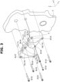
- the internal combustion engine-side mounting bracket 6 is a casting made of metal material such as aluminum alloy. As illustrated in Figs. 2 and 3 , the internal combustion engine-side mounting bracket 6 is connected to the end surfaces, located at one end sides, of the cylinder head 2 and the cylinder block 3 with six bolts 8 of a first bolt 8a to a sixth bolt 8f. The bolts 8 penetrate respective bolt boss portions 9 of the internal combustion engine-side mounting bracket 6.
- the first bolt 8a fixes an upper portion, located at one end side in the internal combustion engine width direction, of the internal combustion engine-side mounting bracket 6 to the cylinder head 2 outside the front cover 5.
- the first bolt 8a penetrates the first bolt boss portion 9a of the internal combustion engine-side mounting bracket 6.
- the second bolt 8b penetrates the front cover 5, and fixes an upper portion, located at the substantially middle in the internal combustion engine width direction, of the internal combustion engine-side mounting bracket 6 to the cylinder head 2.
- the second bolt 8b penetrates the second bolt boss portion 9b of the internal combustion engine-side mounting bracket 6.
- the third bolt 8c fixes an upper portion, located at the other end side in the internal combustion engine width direction, of the internal combustion engine-side mounting bracket 6 to the cylinder head 2 outside the front cover 5.
- the third bolt 8c penetrates the third bolt boss portion 9c of the internal combustion engine-side mounting bracket 6.
- the fourth bolt 8d fixes a lower portion, located at the one end side in the internal combustion engine width direction, of the internal combustion engine-side mounting bracket 6 to the cylinder block 3 outside the front cover 5.
- the fourth bolt 8d penetrates the fourth bolt boss portion 9d of the internal combustion engine-side mounting bracket 6.
- the fifth bolt 8e penetrates the front cover 5, and fixes a lower portion, located at the substantially middle in the internal combustion engine width direction, of the internal combustion engine-side mounting bracket 6 to the cylinder block 3.
- the fifth bolt 8e penetrates the fifth bolt boss portion 9e of the internal combustion engine-side mounting bracket 6.
- the sixth bolt 8f fixes a lower portion, located at the other end side in the internal combustion engine width direction, of the internal combustion engine-side mounting bracket 6 to the cylinder block 3 outside the front cover 5.
- the sixth bolt 8f penetrates the sixth boltboss portion 9f of the internal combustion engine-side mounting bracket 6.
- the internal combustion engine-side mounting bracket 6 has a plurality of (three) mounting portions 10.
- the mounting portions 10 are portions for securing the internal combustion engine 1 to the vehicle body, and their upper end surfaces 11 are fixed to the vehicle body-side mounting brackets 7 with bolts (not shown).
- Each mounting portion 10 is formed by a bulging portion having a semi-cylindrical cross section (or a semi-tubular cross section) that protrudes forward with respect to the end surface, located at one end side, of the internal combustion engine 1. That is, a rear side portion of the mounting portion 10 is hollowed out.
- “forward with respect to the end surface, located at one end side, of the internal combustion engine 1” means “forward with respect to the internal combustion engine 1", and indicates “toward a left side” in Fig. 1 and “frontward (forward) in a direction perpendicular to a paper surface” of Fig. 2 .
- the mounting portion 10 is formed so as to extend in the up-down direction (the vertical direction) along the cylinder axis A of the internal combustion engine 1.
- the mounting portion 10 has a long thin shape (or an elongated shape) extending in the up-down direction (the vertical direction), and its upper end surface 11 is fixed to the vehicle body-side mounting bracket 7.
- the upper end surface 11 is formed so as to be horizontal in a state in which the internal combustion engine 1 is mounted on the vehicle body.
- the mounting portions 10 provided at the internal combustion engine-side mounting bracket 6 are a first mounting portion 10a located at one end side, in the internal combustion engine width direction, of the internal combustion engine-side mounting bracket 6, a second mounting portion 10b located at the other end side, in the internal combustion engine width direction, of the internal combustion engine-side mounting bracket 6, and a third mounting portion 10c located at the middle, in the internal combustion engine width direction, of the internal combustion engine-side mounting bracket 6.
- the first mounting portion 10a and the second mounting portion 10b are a pair of mounting portions located at both sides, in the internal combustion engine width direction, of the internal combustion engine-side mounting bracket 6.
- the first mounting portion 10a its upper end surface 11a is fixed to the vehicle body-side mounting bracket 7. As illustrated in Fig. 2 , the first mounting portion 10a is formed so that the first mounting portion 10a extends in the up-down direction (the vertical direction) along the cylinder axis A of the internal combustion engine 1, and its center line C1 in the up-down direction (the vertical direction) is inclined with respect to the cylinder axis A that is parallel to the Z-axis.
- the first mounting portion 10a is formed obliquely so that its lower end, which is located at a lower side of the internal combustion engine-side mounting bracket 6, is positioned at the one end side in the internal combustion engine width direction with respect to its upper end (the upper end surface 11a), which is located at an upper side of the internal combustion engine-side mounting bracket 6.
- first mounting portion 10a is formed so that its center line C1 is directed toward the fourth bolt 8d where the fourth bolt boss portion 9d penetrates the internal combustion engine-side mounting bracket 6. That is, the first mounting portion 10a is formed so that its lower end is directed toward a securing point of the internal combustion engine-side mounting bracket 6 to the internal combustion engine 1.
- the internal combustion engine-side mounting bracket 6 easily supports or sustains a load received by the upper end surface 11a of the first mounting portion 10a at the securing point to the internal combustion engine 1, thereby improving overall rigidity.
- the second mounting portion 10b its upper end surface 11b is fixed to the vehicle body-side mounting bracket 7. As illustrated in Fig. 2 , the second mounting portion 10b is formed so that the second mounting portion 10b extends in the up-down direction (the vertical direction) along the cylinder axis A of the internal combustion engine 1, and its center line C2 in the up-down direction (the vertical direction) is inclined with respect to the cylinder axis A that is parallel to the Z-axis.
- the second mounting portion 10b is formed obliquely so that its lower end, which is located at the lower side of the internal combustion engine-side mounting bracket 6, is positioned at the other end side in the internal combustion engine width direction with respect to its upper end (the upper end surface 11b), which is located at the upper side of the internal combustion engine-side mounting bracket 6.
- the second mounting portion 10b is formed so that its center line C2 is directed toward the sixth bolt 8f where the sixth bolt boss portion 9f penetrates the internal combustion engine-side mounting bracket 6. That is, the second mounting portion 10b is formed so that its lower end is directed toward a securing point of the internal combustion engine-side mounting bracket 6 to the internal combustion engine 1.
- the internal combustion engine-side mounting bracket 6 easily supports or sustains a load received by the upper end surface 11b of the second mounting portion 10b at the securing point to the internal combustion engine 1, thereby improving overall rigidity.
- the third mounting portion 10c is formed so that its center line C3 is directed toward the fifth bolt 8e where the fifth bolt boss portion 9e penetrates the internal combustion engine-side mounting bracket 6. That is, the third mounting portion 10c is formed so that its lower end is directed toward a securing point of the internal combustion engine-side mounting bracket 6 to the internal combustion engine 1.
- the internal combustion engine-side mounting bracket 6 easily supports or sustains a load received by the upper end surface 11c of the third mounting portion 10c at the securing point to the internal combustion engine 1, thereby improving overall rigidity.
- first mounting portion 10a and the second mounting portion 10b are formed so that an interval between the first mounting portion 10a and the second mounting portion 10b in the internal combustion engine width direction is wider (greater) toward the lower side in the up-down direction (the vertical direction) along the cylinder axis A of the internal combustion engine 1.
- the first mounting portion 10a and the third mounting portion 10c are formed so that an interval between the first mounting portion 10a and the third mounting portion 10c in the internal combustion engine width direction is wider (greater) toward the lower side in the up-down direction (the vertical direction) along the cylinder axis A of the internal combustion engine 1.
- the second mounting portion 10b and the third mounting portion 10c are formed so that an interval between the second mounting portion 10b and the third mounting portion 10c in the internal combustion engine width direction is wider (greater) toward the lower side in the up-down direction (the vertical direction) along the cylinder axis A of the internal combustion engine 1.
- the internal combustion engine-side mounting bracket 6 has a plurality of ribs 12.
- Fig. 4 is a back view of the internal combustion engine-side mounting bracket 6.
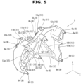
- Figs. 5 and 6 are perspective views of the internal combustion engine-side mounting bracket 6, viewed from its back side (its rear side) .
- the ribs 12 are ribs for increasing rigidity of the internal combustion engine-side mounting bracket 6.
- the ribs 12 connect the securing points of the internal combustion engine-side mounting bracket 6 to the internal combustion engine 1 and connect the mounting portions 10 and the securing points of the internal combustion engine-side mounting bracket 6 to the internal combustion engine 1.
- the ribs 12 connect the bolt boss portions 9 and connect the mounting portions 10 and the bolt boss portions 9.
- the ribs 12 are formed into a ridge shape that protrudes from a back surface of the internal combustion engine-side mounting bracket 6 toward the one end surface side of the internal combustion engine 1.
- the ribs 12 are formed, for instance, as a solid body.
- ten ribs 12 of a first rib 12a to a tenth rib 12j are provided at the internal combustion engine-side mounting bracket 6.
- the first rib 12a corresponds to an upper rib.
- the first rib 12a extends linearly along the internal combustion engine width direction, and connects the first bolt boss portion 9a and the second bolt boss portion 9b. Further, the first rib 12a is connected to an upper end of the first mounting portion 10a.
- the second rib 12b corresponds to an upper rib.
- the second rib 12b extends linearly along the internal combustion engine width direction, and connects the second bolt boss portion 9b and the third bolt boss portion 9c. Further, the second rib 12b is connected to an upper end of the second mounting portion 10b and an upper end of the third mounting portion 10c.
- the third rib 12c corresponds to a lower rib.
- the third rib 12c extends obliquely linearly in the internal combustion engine width direction, and connects the fourth bolt boss portion 9d and the fifth bolt boss portion 9e. Further, the third rib 12c is connected to a lower end of the first mounting portion 10a and a lower end of the third mounting portion 10c.
- the fourth rib 12d corresponds to a lower rib.
- the fourth rib 12d extends obliquely linearly in the internal combustion engine width direction, and connects the fifth bolt boss portion 9e and the sixth bolt boss portion 9f. Further, the fourth rib 12d is connected to a lower end of the second mounting portion 10b and the lower end of the third mounting portion 10c.
- the fifth rib 12e extends linearly along the up-down direction (the vertical direction) along the cylinder axis A of the internal combustion engine 1, and connects the first bolt boss portion 9a and the fourth bolt boss portion 9d. Further, the fifth rib 12e is connected to the lower end of the first mounting portion 10a.
- the sixth rib 12f extends obliquely linearly in the up-down direction (the vertical direction) along the cylinder axis A of the internal combustion engine 1, and connects the second bolt boss portion 9b and the fifth bolt boss portion 9e. Further, the sixth rib 12f is connected to the upper end of the first mounting portion 10a and the lower end of the third mounting portion 10c.
- the seventh rib 12g extends in the up-down direction (the vertical direction) along the cylinder axis A of the internal combustion engine 1, and connects the third bolt boss portion 9c and the sixth bolt boss portion 9f. Further, the seventh rib 12g is formed so as to be curved in an arc shape toward an outer side of the internal combustion engine 1 with respect to the second mounting portion 10b in the internal combustion engine width direction. Then, an upper end of the seventh rib 12g is connected to the upper end of the second mounting portion 10b, and a lower end of the seventh rib 12g is connected to the lower end of the second mounting portion 10b.
- the eighth rib 12h extends obliquely linearly in the up-down direction (the vertical direction) along the cylinder axis A of the internal combustion engine 1, and connects the second bolt boss portion 9b and the fourth bolt boss portion 9d. Further, the eighth rib 12h is connected to the upper end and the lower end of the first mounting portion 10a.
- the ninth rib 12i extends obliquely linearly in the up-down direction (the vertical direction) along the cylinder axis A of the internal combustion engine 1, and connects the second bolt boss portion 9b and the sixth bolt boss portion 9f. Further, the ninth rib 12i is connected to the upper end of the first mounting portion 10a and the lower end of the second mounting portion 10b.
- the internal combustion engine-side mounting bracket 6 in the embodiment described above is made of metal, and has the plurality of mounting portions 10a to 10c formed by the respective bulging portions protruding forward with respect to the end surface, located at one end side, of the internal combustion engine 1. It is therefore possible to form the internal combustion engine-side mounting bracket 6 to be highly rigid and compact without having to form cross-sectional shapes of the mounting portions 10a to 10c to be large, thereby improving the mountability into the vehicle.
- the mounting portions 10 are formed so that the mounting portions 10 extend in the up-down direction (the vertical direction) along the cylinder axis A of the internal combustion engine 1, and their center lines C in the up-down direction (the vertical direction) are inclined with respect to the cylinder axis A that is parallel to the Z-axis. Therefore, rigidity of the internal combustion engine-side mounting bracket 6 in the right-left direction when viewed from the axial direction of the crankshaft of the internal combustion engine 1 can be high, then both the high rigidity and compactness of the internal combustion engine-side mounting bracket 6 can be efficiently achieved.
- the lower ends, in the up-down direction (the vertical direction) along the cylinder axis A of the internal combustion engine 1, of the adjacent mounting portions 10 are connected to each other at the back side by the ribs 12.
- the upper end of the first mounting portion 10a and the upper end of the third mounting portion 10c are connected by the first rib 12a and the second rib 12b.
- the lower end of the first mounting portion 10a and the lower end of the third mounting portion 10c are connected by the third rib 12c. That is, the first mounting portion 10a and the third mounting portion 10c are connected to each other by the first rib 12a, the second rib 12b and the third rib 12c.
- the upper end of the second mounting portion 10b and the upper end of the third mounting portion 10c are connected by the second rib 12b.
- the lower end of the second mounting portion 10b and the lower end of the third mounting portion 10c are connected by the fourth rib 12d. That is, the second mounting portion 10b and the third mounting portion 10c are connected to each other by the second rib 12b and the fourth rib 12d.
- rigidity of the internal combustion engine-side mounting bracket 6 in the right-left direction when viewed from the axial direction of the crankshaft of the internal combustion engine 1 can be high more efficiently, then both the high rigidity and compactness of the internal combustion engine-side mounting bracket 6 can be achieved more efficiently.
- the internal combustion engine-side mounting bracket 6 is formed so that a contour line P formed by connecting the plurality of mounting portions 10 and the plurality of ribs 12 continues annularly when viewed from the axial direction of the crankshaft of the internal combustion engine 1.
- internal combustion engine-side mounting bracket 6 is formed so that the contour line P formed by connecting the first rib 12a and the second rib 12b which connect the upper ends, in the up-down direction (the vertical direction) along the cylinder axis A of the internal combustion engine 1, of the plurality of mounting portions 10a, 10b and 10c at the back side, the third rib 12c and the fourth rib 12d which connect the lower ends, in the up-down direction (the vertical direction) along the cylinder axis A of the internal combustion engine 1, of the plurality of mounting portions 10a, 10b and 10c at the back side, and the first mounting portion 10a and the second mounting portion 10b which are located at both sides, in the internal combustion engine width direction orthogonal to the cylinder line direction of the internal combustion engine 1, of the internal combustion engine-side mounting bracket 6, continues annularly while including the upper ends of the plurality of mounting portions 10a, 10b and 10c and the lower ends of the mounting portions 10a, 10b and 10c when viewed from the axial direction of the cranks
- the securing points of the internal combustion engine-side mounting bracket 6 to the internal combustion engine 1 are connected by the fifth to tenth ribs 12e, 12f, 12g, 12h, 12i and 12j. This can also improve rigidity of the internal combustion engine-side mounting bracket 6.
- the number of the mounting portions 10 is not limited to three, but could be set according to the number of the vehicle body-side mounting brackets 7. That is, for instance, the vehicle body-side mounting bracket 7 fixing the front surface side (the front end side) of the internal combustion engine body to the vehicle body is four in number, the number of the mounting portions 10 is four.
- the internal combustion engine-side mounting bracket 6 may be formed so that the center line C, in the up-down direction, of at least one of the plurality of mounting portions 10 is inclined with respect to the cylinder axis A that is parallel to the Z-axis, and the rest is parallel to the Z-axis.
- the mounting portion 10 may be formed so that its center line C is directed toward the boss portion 9.
- the mounting portion 10 might be formed so that its center line C is not directed toward the bolt 8 and the boss portion 9.
Landscapes
- Engineering & Computer Science (AREA)
- Chemical & Material Sciences (AREA)
- Combustion & Propulsion (AREA)
- Mechanical Engineering (AREA)
- Transportation (AREA)
- General Engineering & Computer Science (AREA)
- Cylinder Crankcases Of Internal Combustion Engines (AREA)
- Arrangement Or Mounting Of Propulsion Units For Vehicles (AREA)
Abstract
Description
- The present invention relates to a mounting bracket for fixing an internal combustion engine to a vehicle body.
- For instance, Patent Document 1 discloses a resin front cover with which a mounting portion for fixing an internal combustion engine to a vehicle body is integrally formed.
- However, since the front cover of Patent Document 1 is made of resin, when attempting to ensure rigidity of the mounting portion, it is necessary for a cross-sectional shape of the mounting portion to be formed large, and consequently, there is a risk that mountability into a vehicle will be deteriorated.
- Patent Document 1: Internal Publication
WO2020/183687 - A mounting bracket of the present invention comprises: a plurality of mounting portions for securing an internal combustion engine to a vehicle body, and the plurality of mounting portions are formed by respective bulging portions protruding forward with respect to an end surface, located at one end side, of the internal combustion engine.
- Since the mounting bracket has the plurality of mounting portions formed by the respective bulging portions, it is possible to form the mounting bracket to be highly rigid and compact, thereby improving the mountability into a vehicle.
-
-
Fig. 1 is an explanatory drawing schematically showing a configuration of an internal combustion engine to which the present invention is applied. -
Fig. 2 is a front view of the internal combustion engine to which an internal combustion engine-side mounting bracket is attached. -
Fig. 3 is an exploded perspective view of a front cover and the internal combustion engine-side mounting bracket which are attached to the internal combustion engine. -
Fig. 4 is a back view of the internal combustion engine-side mounting bracket. -
Fig. 5 is a perspective view of the internal combustion engine-side mounting bracket, viewed from its back side. -
Fig. 6 is a perspective view of the internal combustion engine-side mounting bracket, viewed from its back side. - An embodiment of the present invention will be described in detail below with reference to the drawings. In the drawings, an X-axis indicates an axis along a front-rear direction of an internal combustion engine 1 (an axis parallel to a center axis of a crankshaft of the internal combustion engine 1), a Y-axis indicates an axis along a right-left direction of the internal combustion engine 1 (an axis along a width direction of the internal combustion engine 1), and a Z-axis indicates an axis along an up-down direction (a vertical direction) of the internal combustion engine 1 (an axis parallel to a cylinder axis A of the internal combustion engine 1).
-
Fig. 1 is an explanatory drawing schematically showing a configuration of the internal combustion engine 1 to which the present invention is applied. - The internal combustion engine 1 is, for instance, an in-line multi-cylinder internal combustion engine. The internal combustion engine 1 has a
cylinder head 2, acylinder block 3 fixed to a lower portion of thecylinder head 2, acam bracket 4 fixed to an upper portion of thecylinder head 2, afront cover 5 covering a front surface of the internal combustion engine 1 and a metal internal combustion engine-side mounting bracket 6 arranged on a front surface of thefront cover 5. InFig. 1 , areference sign 7 is a vehicle body-side mounting bracket fixed to a vehicle body side. - The
cylinder head 2 is a casting made of metal material such as aluminum alloy. An intake port (not shown) for supplying intake air into a combustion chamber (not shown) and an exhaust port (not shown) for exhausting exhaust gas from the combustion chamber (not shown) are formed at thecylinder head 2. - The
cylinder block 3 is a casting made of metal material such as aluminum alloy, and has cylinders (not shown) whose number corresponds to the number of the cylinders. - The
cam bracket 4 is made of metal material such as aluminum alloy. Thecam bracket 4 rotatably supports a camshaft (not shown) together with thecylinder head 2. - The
front cover 5 is made of synthetic resin material such as polyamide. Thefront cover 5 is attached to an internal combustion engine body so as to cover a front surface of the internal combustion engine body. More specifically, thefront cover 5 is secured to a front surface of thecylinder block 3, a front surface of thecylinder head 2, a front surface of thecam bracket 4 etc. with bolts (not shown). In other words, thefront cover 5 is arranged so as to cover end surfaces, located at one end sides in the crankshaft axial direction, of thecylinder block 3 and thecylinder head 2, i.e. so as to cover an end surface, located at one end side in a cylinder line direction, of the internal combustion engine body. Here, thefront cover 5 may be a casting made of metal material such as aluminum alloy. - The
front cover 5 accommodates a crank sprocket (not shown) fixed to a front end of the crankshaft (not shown) and a cam sprocket (not shown) fixed to a front end of the camshaft (not shown) in a space formed between thefront cover 5 and the front surface of the internal combustion engine body. A timing chain (not shown) for transmitting rotation power is would around these crank sprocket and cam sprocket. - The internal combustion engine-
side mounting bracket 6 corresponds to a mounting bracket, and is secured to the end surface, located at one end side in the cylinder line direction, of the internal combustion engine 1. The internal combustion engine-side mounting bracket 6 is a casting made of metal material such as aluminum alloy. As illustrated inFigs. 2 and3 , the internal combustion engine-side mounting bracket 6 is connected to the end surfaces, located at one end sides, of thecylinder head 2 and thecylinder block 3 with sixbolts 8 of afirst bolt 8a to asixth bolt 8f. Thebolts 8 penetrate respectivebolt boss portions 9 of the internal combustion engine-side mounting bracket 6. - As illustrated in
Figs. 2 and3 , the internal combustion engine-side mounting bracket 6 has sixbolt boss portions 9 of a firstbolt boss portion 9a to a sixthbolt boss portion 9f.Fig. 2 is a front view of the internal combustion engine 1 to which the internal combustion engine-side mounting bracket 6 is attached.Fig. 3 is an exploded perspective view of thefront cover 5 and the internal combustion engine-side mounting bracket 6 which are attached to the internal combustion engine 1. - The
first bolt 8a fixes an upper portion, located at one end side in the internal combustion engine width direction, of the internal combustion engine-side mounting bracket 6 to thecylinder head 2 outside thefront cover 5. Thefirst bolt 8a penetrates the firstbolt boss portion 9a of the internal combustion engine-side mounting bracket 6. - The
second bolt 8b penetrates thefront cover 5, and fixes an upper portion, located at the substantially middle in the internal combustion engine width direction, of the internal combustion engine-side mounting bracket 6 to thecylinder head 2. Thesecond bolt 8b penetrates the secondbolt boss portion 9b of the internal combustion engine-side mounting bracket 6. - The
third bolt 8c fixes an upper portion, located at the other end side in the internal combustion engine width direction, of the internal combustion engine-side mounting bracket 6 to thecylinder head 2 outside thefront cover 5. Thethird bolt 8c penetrates the thirdbolt boss portion 9c of the internal combustion engine-side mounting bracket 6. - The
fourth bolt 8d fixes a lower portion, located at the one end side in the internal combustion engine width direction, of the internal combustion engine-side mounting bracket 6 to thecylinder block 3 outside thefront cover 5. Thefourth bolt 8d penetrates the fourthbolt boss portion 9d of the internal combustion engine-side mounting bracket 6. - The
fifth bolt 8e penetrates thefront cover 5, and fixes a lower portion, located at the substantially middle in the internal combustion engine width direction, of the internal combustion engine-side mounting bracket 6 to thecylinder block 3. Thefifth bolt 8e penetrates the fifthbolt boss portion 9e of the internal combustion engine-side mounting bracket 6. - The
sixth bolt 8f fixes a lower portion, located at the other end side in the internal combustion engine width direction, of the internal combustion engine-side mounting bracket 6 to thecylinder block 3 outside thefront cover 5. Thesixth bolt 8f penetrates thesixth boltboss portion 9f of the internal combustion engine-side mounting bracket 6. - As illustrated in
Figs. 2 and3 , the internal combustion engine-side mounting bracket 6 has a plurality of (three) mountingportions 10. Themounting portions 10 are portions for securing the internal combustion engine 1 to the vehicle body, and theirupper end surfaces 11 are fixed to the vehicle body-side mounting brackets 7 with bolts (not shown). - Each
mounting portion 10 is formed by a bulging portion having a semi-cylindrical cross section (or a semi-tubular cross section) that protrudes forward with respect to the end surface, located at one end side, of the internal combustion engine 1. That is, a rear side portion of themounting portion 10 is hollowed out. Here, "forward with respect to the end surface, located at one end side, of the internal combustion engine 1" means "forward with respect to the internal combustion engine 1", and indicates "toward a left side" inFig. 1 and "frontward (forward) in a direction perpendicular to a paper surface" ofFig. 2 . Themounting portion 10 is formed so as to extend in the up-down direction (the vertical direction) along the cylinder axis A of the internal combustion engine 1. That is, themounting portion 10 has a long thin shape (or an elongated shape) extending in the up-down direction (the vertical direction), and itsupper end surface 11 is fixed to the vehicle body-side mounting bracket 7. Theupper end surface 11 is formed so as to be horizontal in a state in which the internal combustion engine 1 is mounted on the vehicle body. - The
mounting portions 10 provided at the internal combustion engine-side mounting bracket 6 are afirst mounting portion 10a located at one end side, in the internal combustion engine width direction, of the internal combustion engine-side mounting bracket 6, asecond mounting portion 10b located at the other end side, in the internal combustion engine width direction, of the internal combustion engine-side mounting bracket 6, and athird mounting portion 10c located at the middle, in the internal combustion engine width direction, of the internal combustion engine-side mounting bracket 6. The first mountingportion 10a and the second mountingportion 10b are a pair of mounting portions located at both sides, in the internal combustion engine width direction, of the internal combustion engine-side mounting bracket 6. - Regarding the first mounting
portion 10a, itsupper end surface 11a is fixed to the vehicle body-side mounting bracket 7. As illustrated inFig. 2 , the first mountingportion 10a is formed so that the first mountingportion 10a extends in the up-down direction (the vertical direction) along the cylinder axis A of the internal combustion engine 1, and its center line C1 in the up-down direction (the vertical direction) is inclined with respect to the cylinder axis A that is parallel to the Z-axis. More specifically, the first mountingportion 10a is formed obliquely so that its lower end, which is located at a lower side of the internal combustion engine-side mounting bracket 6, is positioned at the one end side in the internal combustion engine width direction with respect to its upper end (theupper end surface 11a), which is located at an upper side of the internal combustion engine-side mounting bracket 6. - Further, the first mounting
portion 10a is formed so that its center line C1 is directed toward thefourth bolt 8d where the fourthbolt boss portion 9d penetrates the internal combustion engine-side mounting bracket 6. That is, the first mountingportion 10a is formed so that its lower end is directed toward a securing point of the internal combustion engine-side mounting bracket 6 to the internal combustion engine 1. - With this, the internal combustion engine-
side mounting bracket 6 easily supports or sustains a load received by theupper end surface 11a of the first mountingportion 10a at the securing point to the internal combustion engine 1, thereby improving overall rigidity. - Regarding the second mounting
portion 10b, itsupper end surface 11b is fixed to the vehicle body-side mounting bracket 7. As illustrated inFig. 2 , the second mountingportion 10b is formed so that the second mountingportion 10b extends in the up-down direction (the vertical direction) along the cylinder axis A of the internal combustion engine 1, and its center line C2 in the up-down direction (the vertical direction) is inclined with respect to the cylinder axis A that is parallel to the Z-axis. More specifically, the second mountingportion 10b is formed obliquely so that its lower end, which is located at the lower side of the internal combustion engine-side mounting bracket 6, is positioned at the other end side in the internal combustion engine width direction with respect to its upper end (theupper end surface 11b), which is located at the upper side of the internal combustion engine-side mounting bracket 6. - Further, the second mounting
portion 10b is formed so that its center line C2 is directed toward thesixth bolt 8f where the sixthbolt boss portion 9f penetrates the internal combustion engine-side mounting bracket 6. That is, the second mountingportion 10b is formed so that its lower end is directed toward a securing point of the internal combustion engine-side mounting bracket 6 to the internal combustion engine 1. - With this, the internal combustion engine-
side mounting bracket 6 easily supports or sustains a load received by theupper end surface 11b of the second mountingportion 10b at the securing point to the internal combustion engine 1, thereby improving overall rigidity. - Regarding the third mounting
portion 10c, itsupper end surface 11c is fixed to the vehicle body-side mounting bracket 7. As illustrated inFig. 2 , the third mountingportion 10c is formed so that the third mountingportion 10c extends in the up-down direction (the vertical direction) along the cylinder axis A of the internal combustion engine 1, and its center line C3 in the up-down direction (the vertical direction) is inclined with respect to the cylinder axis A that is parallel to the Z-axis. More specifically, the third mountingportion 10c is formed obliquely so that its lower end, which is located at the lower side of the internal combustion engine-side mounting bracket 6, is positioned at the one end side in the internal combustion engine width direction with respect to its upper end (theupper end surface 11c), which is located at the upper side of the internal combustion engine-side mounting bracket 6. - Further, the third mounting
portion 10c is formed so that its center line C3 is directed toward thefifth bolt 8e where the fifthbolt boss portion 9e penetrates the internal combustion engine-side mounting bracket 6. That is, the third mountingportion 10c is formed so that its lower end is directed toward a securing point of the internal combustion engine-side mounting bracket 6 to the internal combustion engine 1. - With this, the internal combustion engine-
side mounting bracket 6 easily supports or sustains a load received by theupper end surface 11c of the third mountingportion 10c at the securing point to the internal combustion engine 1, thereby improving overall rigidity. - Further, the first mounting
portion 10a and the second mountingportion 10b are formed so that an interval between the first mountingportion 10a and the second mountingportion 10b in the internal combustion engine width direction is wider (greater) toward the lower side in the up-down direction (the vertical direction) along the cylinder axis A of the internal combustion engine 1. The first mountingportion 10a and the third mountingportion 10c are formed so that an interval between the first mountingportion 10a and the third mountingportion 10c in the internal combustion engine width direction is wider (greater) toward the lower side in the up-down direction (the vertical direction) along the cylinder axis A of the internal combustion engine 1. - The
second mounting portion 10b and the third mountingportion 10c are formed so that an interval between the second mountingportion 10b and the third mountingportion 10c in the internal combustion engine width direction is wider (greater) toward the lower side in the up-down direction (the vertical direction) along the cylinder axis A of the internal combustion engine 1. - As illustrated in
Figs. 4 to 6 , the internal combustion engine-side mounting bracket 6 has a plurality ofribs 12.Fig. 4 is a back view of the internal combustion engine-side mounting bracket 6.Figs. 5 and6 are perspective views of the internal combustion engine-side mounting bracket 6, viewed from its back side (its rear side) . - The
ribs 12 are ribs for increasing rigidity of the internal combustion engine-side mounting bracket 6. Theribs 12 connect the securing points of the internal combustion engine-side mounting bracket 6 to the internal combustion engine 1 and connect the mountingportions 10 and the securing points of the internal combustion engine-side mounting bracket 6 to the internal combustion engine 1. In other words, theribs 12 connect thebolt boss portions 9 and connect the mountingportions 10 and thebolt boss portions 9. Theribs 12 are formed into a ridge shape that protrudes from a back surface of the internal combustion engine-side mounting bracket 6 toward the one end surface side of the internal combustion engine 1. Theribs 12 are formed, for instance, as a solid body. - In the present embodiment, ten
ribs 12 of afirst rib 12a to atenth rib 12j are provided at the internal combustion engine-side mounting bracket 6. - The
first rib 12a corresponds to an upper rib. Thefirst rib 12a extends linearly along the internal combustion engine width direction, and connects the firstbolt boss portion 9a and the secondbolt boss portion 9b. Further, thefirst rib 12a is connected to an upper end of the first mountingportion 10a. - The
second rib 12b corresponds to an upper rib. Thesecond rib 12b extends linearly along the internal combustion engine width direction, and connects the secondbolt boss portion 9b and the thirdbolt boss portion 9c. Further, thesecond rib 12b is connected to an upper end of the second mountingportion 10b and an upper end of the third mountingportion 10c. - The
third rib 12c corresponds to a lower rib. Thethird rib 12c extends obliquely linearly in the internal combustion engine width direction, and connects the fourthbolt boss portion 9d and the fifthbolt boss portion 9e. Further, thethird rib 12c is connected to a lower end of the first mountingportion 10a and a lower end of the third mountingportion 10c. - The
fourth rib 12d corresponds to a lower rib. Thefourth rib 12d extends obliquely linearly in the internal combustion engine width direction, and connects the fifthbolt boss portion 9e and the sixthbolt boss portion 9f. Further, thefourth rib 12d is connected to a lower end of the second mountingportion 10b and the lower end of the third mountingportion 10c. - The
fifth rib 12e extends linearly along the up-down direction (the vertical direction) along the cylinder axis A of the internal combustion engine 1, and connects the firstbolt boss portion 9a and the fourthbolt boss portion 9d. Further, thefifth rib 12e is connected to the lower end of the first mountingportion 10a. - The
sixth rib 12f extends obliquely linearly in the up-down direction (the vertical direction) along the cylinder axis A of the internal combustion engine 1, and connects the secondbolt boss portion 9b and the fifthbolt boss portion 9e. Further, thesixth rib 12f is connected to the upper end of the first mountingportion 10a and the lower end of the third mountingportion 10c. - The
seventh rib 12g extends in the up-down direction (the vertical direction) along the cylinder axis A of the internal combustion engine 1, and connects the thirdbolt boss portion 9c and the sixthbolt boss portion 9f. Further, theseventh rib 12g is formed so as to be curved in an arc shape toward an outer side of the internal combustion engine 1 with respect to the second mountingportion 10b in the internal combustion engine width direction. Then, an upper end of theseventh rib 12g is connected to the upper end of the second mountingportion 10b, and a lower end of theseventh rib 12g is connected to the lower end of the second mountingportion 10b. - The
eighth rib 12h extends obliquely linearly in the up-down direction (the vertical direction) along the cylinder axis A of the internal combustion engine 1, and connects the secondbolt boss portion 9b and the fourthbolt boss portion 9d. Further, theeighth rib 12h is connected to the upper end and the lower end of the first mountingportion 10a. - The
ninth rib 12i extends obliquely linearly in the up-down direction (the vertical direction) along the cylinder axis A of the internal combustion engine 1, and connects the secondbolt boss portion 9b and the sixthbolt boss portion 9f. Further, theninth rib 12i is connected to the upper end of the first mountingportion 10a and the lower end of the second mountingportion 10b. - The
tenth rib 12j extends obliquely linearly in the up-down direction (the vertical direction) along the cylinder axis A of the internal combustion engine 1, and connects the upper end of the second mountingportion 10b and the fifthbolt boss portion 9e. Further, thetenth rib 12j is formed so as to cross the third mountingportion 10c. - The internal combustion engine-
side mounting bracket 6 in the embodiment described above is made of metal, and has the plurality of mountingportions 10a to 10c formed by the respective bulging portions protruding forward with respect to the end surface, located at one end side, of the internal combustion engine 1. It is therefore possible to form the internal combustion engine-side mounting bracket 6 to be highly rigid and compact without having to form cross-sectional shapes of the mountingportions 10a to 10c to be large, thereby improving the mountability into the vehicle. - Further, the mounting
portions 10 are formed so as to extend in the up-down direction (the vertical direction) along the cylinder axis A of the internal combustion engine 1. Therefore, rigidity of the internal combustion engine-side mounting bracket 6 in the up-down direction can be high, then both the high rigidity and compactness of the internal combustion engine-side mounting bracket 6 can be efficiently achieved. - The mounting
portions 10 are formed so that the mountingportions 10 extend in the up-down direction (the vertical direction) along the cylinder axis A of the internal combustion engine 1, and their center lines C in the up-down direction (the vertical direction) are inclined with respect to the cylinder axis A that is parallel to the Z-axis. Therefore, rigidity of the internal combustion engine-side mounting bracket 6 in the right-left direction when viewed from the axial direction of the crankshaft of the internal combustion engine 1 can be high, then both the high rigidity and compactness of the internal combustion engine-side mounting bracket 6 can be efficiently achieved. - The lower ends, in the up-down direction (the vertical direction) along the cylinder axis A of the internal combustion engine 1, of the adjacent mounting
portions 10 are connected to each other at the back side by theribs 12. - More specifically, the upper end of the first mounting
portion 10a and the upper end of the third mountingportion 10c are connected by thefirst rib 12a and thesecond rib 12b. The lower end of the first mountingportion 10a and the lower end of the third mountingportion 10c are connected by thethird rib 12c. That is, the first mountingportion 10a and the third mountingportion 10c are connected to each other by thefirst rib 12a, thesecond rib 12b and thethird rib 12c. Also, the upper end of the second mountingportion 10b and the upper end of the third mountingportion 10c are connected by thesecond rib 12b. The lower end of the second mountingportion 10b and the lower end of the third mountingportion 10c are connected by thefourth rib 12d. That is, the second mountingportion 10b and the third mountingportion 10c are connected to each other by thesecond rib 12b and thefourth rib 12d. - With this, rigidity of the internal combustion engine-
side mounting bracket 6 in the right-left direction when viewed from the axial direction of the crankshaft of the internal combustion engine 1 can be high more efficiently, then both the high rigidity and compactness of the internal combustion engine-side mounting bracket 6 can be achieved more efficiently. - The internal combustion engine-
side mounting bracket 6 is formed so that a contour line P formed by connecting the plurality of mountingportions 10 and the plurality ofribs 12 continues annularly when viewed from the axial direction of the crankshaft of the internal combustion engine 1. - More specifically, internal combustion engine-
side mounting bracket 6 is formed so that the contour line P formed by connecting thefirst rib 12a and thesecond rib 12b which connect the upper ends, in the up-down direction (the vertical direction) along the cylinder axis A of the internal combustion engine 1, of the plurality of mountingportions third rib 12c and thefourth rib 12d which connect the lower ends, in the up-down direction (the vertical direction) along the cylinder axis A of the internal combustion engine 1, of the plurality of mountingportions portion 10a and the second mountingportion 10b which are located at both sides, in the internal combustion engine width direction orthogonal to the cylinder line direction of the internal combustion engine 1, of the internal combustion engine-side mounting bracket 6, continues annularly while including the upper ends of the plurality of mountingportions portions - With this, since the contour line P formed by connecting the plurality of mounting
portions ribs side mounting bracket 6 can beincreased more efficiently. - Further, the securing points of the internal combustion engine-
side mounting bracket 6 to the internal combustion engine 1 are connected by the fifth totenth ribs side mounting bracket 6. - Although the specific embodiment of the present invention has been described, the present invention is not limited to the above embodiment, and can be realized in various configurations without departing from the scope of the present invention.
- For instance, the number of the mounting
portions 10 is not limited to three, but could be set according to the number of the vehicle body-side mounting brackets 7. That is, for instance, the vehicle body-side mounting bracket 7 fixing the front surface side (the front end side) of the internal combustion engine body to the vehicle body is four in number, the number of the mountingportions 10 is four. - Furthermore, the internal combustion engine-
side mounting bracket 6 may be formed so that the center line C, in the up-down direction, of at least one of the plurality of mountingportions 10 is inclined with respect to the cylinder axis A that is parallel to the Z-axis, and the rest is parallel to the Z-axis. - Moreover, the mounting
portion 10 may be formed so that its center line C is directed toward theboss portion 9. In addition, the mountingportion 10 might be formed so that its center line C is not directed toward thebolt 8 and theboss portion 9.
Claims (5)
- A mounting bracket fixed to an end surface, located at one end side in a cylinder line direction, of an internal combustion engine, the mounting bracket comprising:a plurality of mounting portions for securing the internal combustion engine to a vehicle body, whereinthe plurality of mounting portions are formed by respective bulging portions protruding forward with respect to the end surface, located at the one end side, of the internal combustion engine.
- The mounting bracket as claimed in claim 1, wherein
the plurality of mounting portions are formed so as to extend in an up-down direction along a cylinder axis of the internal combustion engine. - The mounting bracket as claimed in claim 2, wherein
at least one of the plurality of mounting portions is formed so that its center line in the up-down direction is inclined with respect to the cylinder axis when viewed from an axial direction of a crankshaft of the internal combustion engine. - The mounting bracket as claimed in claim 2 or 3, wherein
the adjacent mounting portions are connected to each other by ribs. - The mounting bracket as claimed in claim 2 or 3, further comprising:a plurality of ribs connected to the plurality of mounting portions,wherein the mounting bracket is formed so that a contour line formed by connecting the plurality of mounting portions and the plurality of ribs continues annularly when viewed from an axial direction of a crankshaft of the internal combustion engine.
Applications Claiming Priority (1)
| Application Number | Priority Date | Filing Date | Title |
|---|---|---|---|
| PCT/JP2022/022737 WO2023238176A1 (en) | 2022-06-06 | 2022-06-06 | Mounting bracket |
Publications (2)
| Publication Number | Publication Date |
|---|---|
| EP4538083A1 true EP4538083A1 (en) | 2025-04-16 |
| EP4538083A4 EP4538083A4 (en) | 2025-11-05 |
Family
ID=89117965
Family Applications (1)
| Application Number | Title | Priority Date | Filing Date |
|---|---|---|---|
| EP22945132.3A Pending EP4538083A4 (en) | 2022-06-06 | 2022-06-06 | Mounting bracket |
Country Status (3)
| Country | Link |
|---|---|
| EP (1) | EP4538083A4 (en) |
| CN (1) | CN119212884A (en) |
| WO (1) | WO2023238176A1 (en) |
Family Cites Families (9)
| Publication number | Priority date | Publication date | Assignee | Title |
|---|---|---|---|---|
| DE19636820C2 (en) * | 1996-09-11 | 2000-01-27 | Ford Global Tech Inc | Device for receiving an engine mounting of an internal combustion engine |
| JP2001199248A (en) * | 2000-01-14 | 2001-07-24 | Suzuki Motor Corp | Engine mounting structure |
| DE10206472A1 (en) * | 2002-02-16 | 2003-08-28 | Volkswagen Ag | Support system for engine and gearbox of vehicle comprises bearings at rear of engine and rear of gearbox, supplementary bearing between engine and chassis functioning when torque exceeds threshold value |
| JP2010116020A (en) * | 2008-11-12 | 2010-05-27 | Toyota Motor Corp | Engine support structure |
| JP6885240B2 (en) * | 2017-07-13 | 2021-06-09 | スズキ株式会社 | Internal combustion engine for vehicles |
| JP7107054B2 (en) * | 2018-07-20 | 2022-07-27 | スズキ株式会社 | Internal combustion engine cover structure |
| JP7135533B2 (en) * | 2018-07-20 | 2022-09-13 | スズキ株式会社 | Internal combustion engine cover structure |
| JP7213949B2 (en) | 2019-03-14 | 2023-01-27 | 日産自動車株式会社 | internal combustion engine |
| CN112009568B (en) * | 2019-05-30 | 2022-10-28 | 马自达汽车株式会社 | Powertrain support structure of vehicle |
-
2022
- 2022-06-06 WO PCT/JP2022/022737 patent/WO2023238176A1/en not_active Ceased
- 2022-06-06 EP EP22945132.3A patent/EP4538083A4/en active Pending
- 2022-06-06 CN CN202280096163.7A patent/CN119212884A/en active Pending
Also Published As
| Publication number | Publication date |
|---|---|
| EP4538083A4 (en) | 2025-11-05 |
| JPWO2023238176A1 (en) | 2023-12-14 |
| WO2023238176A1 (en) | 2023-12-14 |
| CN119212884A (en) | 2024-12-27 |
Similar Documents
| Publication | Publication Date | Title |
|---|---|---|
| EP2187018B1 (en) | Cover secured to engine | |
| US11623506B2 (en) | Internal combustion engine | |
| US10364741B2 (en) | Internal combustion engine provided with turbocharger | |
| JP7859494B2 (en) | Mounting bracket | |
| JP6613808B2 (en) | Engine and motorcycle | |
| JP6206300B2 (en) | Power transmission device | |
| WO2023238176A1 (en) | Mounting bracket | |
| JP3736254B2 (en) | Cylinder block of multi-cylinder internal combustion engine | |
| US6179582B1 (en) | Oil pump attachment structure for engine | |
| JP2003201928A (en) | Engine intake system support structure | |
| JP7308169B2 (en) | internal combustion engine front cover | |
| JP3619340B2 (en) | Cylinder block structure in V-type internal combustion engine for vehicle | |
| JP2021055584A (en) | Main body block of multicylinder internal combustion engine | |
| JP7841500B2 (en) | V-type internal combustion engine | |
| JP5912736B2 (en) | Internal combustion engine | |
| EP4538522A1 (en) | Internal combustion engine | |
| KR101046324B1 (en) | Fixed structure of exhaust gas reduction device of automobile diesel engine | |
| JP5097071B2 (en) | Bearing cap structure | |
| JP2824090B2 (en) | Multi-cylinder engine intake system | |
| JP4374615B2 (en) | Cylinder block structure of V-type engine | |
| JP2025144704A (en) | Turbocharged internal combustion engine | |
| JP2004293384A (en) | Supporting device for auxiliary machine of engine | |
| JP2989777B2 (en) | 4 cycle engine | |
| CN122070226A (en) | internal combustion engine | |
| JPH11236859A (en) | Engine intake system |
Legal Events
| Date | Code | Title | Description |
|---|---|---|---|
| STAA | Information on the status of an ep patent application or granted ep patent |
Free format text: STATUS: THE INTERNATIONAL PUBLICATION HAS BEEN MADE |
|
| PUAI | Public reference made under article 153(3) epc to a published international application that has entered the european phase |
Free format text: ORIGINAL CODE: 0009012 |
|
| STAA | Information on the status of an ep patent application or granted ep patent |
Free format text: STATUS: REQUEST FOR EXAMINATION WAS MADE |
|
| 17P | Request for examination filed |
Effective date: 20241209 |
|
| AK | Designated contracting states |
Kind code of ref document: A1 Designated state(s): AL AT BE BG CH CY CZ DE DK EE ES FI FR GB GR HR HU IE IS IT LI LT LU LV MC MK MT NL NO PL PT RO RS SE SI SK SM TR |
|
| DAV | Request for validation of the european patent (deleted) | ||
| DAX | Request for extension of the european patent (deleted) | ||
| A4 | Supplementary search report drawn up and despatched |
Effective date: 20251009 |
|
| RIC1 | Information provided on ipc code assigned before grant |
Ipc: B60K 5/12 20060101AFI20251002BHEP Ipc: F02F 7/00 20060101ALI20251002BHEP |
|
| STAA | Information on the status of an ep patent application or granted ep patent |
Free format text: STATUS: EXAMINATION IS IN PROGRESS |
|
| 17Q | First examination report despatched |
Effective date: 20260316 |