EP4538068A1 - Lenker für eine radaufhängung in einem kraftfahrzeug - Google Patents
Lenker für eine radaufhängung in einem kraftfahrzeug Download PDFInfo
- Publication number
- EP4538068A1 EP4538068A1 EP23202766.4A EP23202766A EP4538068A1 EP 4538068 A1 EP4538068 A1 EP 4538068A1 EP 23202766 A EP23202766 A EP 23202766A EP 4538068 A1 EP4538068 A1 EP 4538068A1
- Authority
- EP
- European Patent Office
- Prior art keywords
- base plate
- eccentric
- handlebar
- elongated hole
- anchor body
- Prior art date
- Legal status (The legal status is an assumption and is not a legal conclusion. Google has not performed a legal analysis and makes no representation as to the accuracy of the status listed.)
- Granted
Links
Images

Classifications
-
- B—PERFORMING OPERATIONS; TRANSPORTING
- B60—VEHICLES IN GENERAL
- B60G—VEHICLE SUSPENSION ARRANGEMENTS
- B60G7/00—Pivoted suspension arms; Accessories thereof
- B60G7/001—Suspension arms, e.g. constructional features
-
- B—PERFORMING OPERATIONS; TRANSPORTING
- B60—VEHICLES IN GENERAL
- B60G—VEHICLE SUSPENSION ARRANGEMENTS
- B60G3/00—Resilient suspensions for a single wheel
- B60G3/02—Resilient suspensions for a single wheel with a single pivoted arm
-
- B—PERFORMING OPERATIONS; TRANSPORTING
- B60—VEHICLES IN GENERAL
- B60G—VEHICLE SUSPENSION ARRANGEMENTS
- B60G2200/00—Indexing codes relating to suspension types
- B60G2200/40—Indexing codes relating to the wheels in the suspensions
- B60G2200/46—Indexing codes relating to the wheels in the suspensions camber angle
-
- B—PERFORMING OPERATIONS; TRANSPORTING
- B60—VEHICLES IN GENERAL
- B60G—VEHICLE SUSPENSION ARRANGEMENTS
- B60G2200/00—Indexing codes relating to suspension types
- B60G2200/40—Indexing codes relating to the wheels in the suspensions
- B60G2200/462—Toe-in/out
-
- B—PERFORMING OPERATIONS; TRANSPORTING
- B60—VEHICLES IN GENERAL
- B60G—VEHICLE SUSPENSION ARRANGEMENTS
- B60G2204/00—Indexing codes related to suspensions per se or to auxiliary parts
- B60G2204/40—Auxiliary suspension parts; Adjustment of suspensions
- B60G2204/44—Centering or positioning means
-
- B—PERFORMING OPERATIONS; TRANSPORTING
- B60—VEHICLES IN GENERAL
- B60G—VEHICLE SUSPENSION ARRANGEMENTS
- B60G2206/00—Indexing codes related to the manufacturing of suspensions: constructional features, the materials used, procedures or tools
- B60G2206/01—Constructional features of suspension elements, e.g. arms, dampers, springs
-
- B—PERFORMING OPERATIONS; TRANSPORTING
- B60—VEHICLES IN GENERAL
- B60G—VEHICLE SUSPENSION ARRANGEMENTS
- B60G2206/00—Indexing codes related to the manufacturing of suspensions: constructional features, the materials used, procedures or tools
- B60G2206/01—Constructional features of suspension elements, e.g. arms, dampers, springs
- B60G2206/70—Materials used in suspensions
-
- B—PERFORMING OPERATIONS; TRANSPORTING
- B60—VEHICLES IN GENERAL
- B60G—VEHICLE SUSPENSION ARRANGEMENTS
- B60G2206/00—Indexing codes related to the manufacturing of suspensions: constructional features, the materials used, procedures or tools
- B60G2206/01—Constructional features of suspension elements, e.g. arms, dampers, springs
- B60G2206/70—Materials used in suspensions
- B60G2206/71—Light weight materials
- B60G2206/7102—Aluminium alloys
-
- B—PERFORMING OPERATIONS; TRANSPORTING
- B60—VEHICLES IN GENERAL
- B60G—VEHICLE SUSPENSION ARRANGEMENTS
- B60G2206/00—Indexing codes related to the manufacturing of suspensions: constructional features, the materials used, procedures or tools
- B60G2206/01—Constructional features of suspension elements, e.g. arms, dampers, springs
- B60G2206/70—Materials used in suspensions
- B60G2206/72—Steel
-
- B—PERFORMING OPERATIONS; TRANSPORTING
- B60—VEHICLES IN GENERAL
- B60G—VEHICLE SUSPENSION ARRANGEMENTS
- B60G2206/00—Indexing codes related to the manufacturing of suspensions: constructional features, the materials used, procedures or tools
- B60G2206/01—Constructional features of suspension elements, e.g. arms, dampers, springs
- B60G2206/80—Manufacturing procedures
- B60G2206/82—Joining
- B60G2206/8209—Joining by deformation
- B60G2206/82092—Joining by deformation by press-fitting
Definitions
- the invention relates to a control arm for a wheel suspension in a motor vehicle with a control arm body made of light metal, in particular aluminum, which has two parallel side walls, wherein an elongated hole for an eccentric holder is provided in at least one side wall.
- Control arms are components of a motor vehicle's wheel suspension. These control arms must absorb high radial forces, such as braking and drive forces. In addition, the control arms, in conjunction with other chassis components, support the weight of a vehicle.
- An eccentric adjustment device which usually has eccentric elements such as eccentric discs or eccentric screws and/or control elements, can be used to align a control arm relative to the wheel carrier connection. In this way, vehicle tolerances can be compensated and track and/or The camber of a motor vehicle's wheels can be adjusted.
- the eccentric adjustment device interacts with elongated holes in the side walls of the handlebar, where it can be secured via an eccentric mount.
- the state of the art includes designs of handlebars with eccentric adjustment devices as in the US 2020/0361265 A1 , the DE 10 2019 020 874 A1 or the KR 100907068 B1 revealed.
- the handlebar bodies are often made of light metal or a light metal alloy, in particular from the 5000 series to the 7000 series aluminum.
- Handlebar bodies made of light alloy offer the advantage of lighter weight. However, these components are also susceptible to damage and wear due to the high forces and torques exerted during operation. The handlebar bodies can also be damaged during assembly or during adjustment of the camber and camber angles. This also applies to handlebar bodies made of other lightweight materials, such as fiber-reinforced plastics.
- the invention is based on the object of providing a lightweight and functionally improved handlebar which is improved in particular with regard to wear protection in the area of the connection of an eccentric adjustment device to or in the side walls of the handlebar body.
- a control arm according to the invention for a wheel suspension in a motor vehicle has a control arm body.
- the control arm body is made of light metal, Preferably made of aluminum or an aluminum alloy from the 5000 series to the 7000 series.
- the control arm body has two side walls, particularly parallel to each other.
- a slotted hole for an eccentric mount is provided in at least one side wall. The eccentric mount interacts with an eccentric adjustment device. Using the eccentric adjustment device, the relative position of the control arm to the wheel suspension can be determined and the camber and toe angles can be adjusted.
- the eccentric bracket can be secured on or in the elongated hole of a side wall.
- the eccentric bracket has a base plate with an elongated hole opening, wherein an anchor body is provided on the rear of the base plate and is arranged at the edge of the elongated hole opening.
- Two eccentric stops protruding from the base plate are arranged at the front of the base plate.
- the eccentric stops, which are arranged in particular at the edge of the base plate, serve as a control track for an actuating element of the eccentric adjustment device, such as in particular an eccentric disc.
- the eccentric bracket is press-fitted to the anchor body in the elongated hole.
- the anchor body of the eccentric bracket and the elongated hole in the side wall of the link are manufactured and configured to one another in such a way that a press fit is created at the connection points after joining. This allows longitudinal and transverse forces to be transmitted in a force-locking manner.
- the eccentric mount according to the invention provides a protective function in a component against wear or damage during adjustment of toe and camber and also functions as an eccentric disc stop for an eccentric adjustment device.
- the area in or around the elongated hole in the sidewall of the handlebar body is protected from wear and damage.
- the eccentric mount according to the invention is pressed and press-fitted with the anchor body into the slotted hole in the side wall of the handlebar body.
- the joint is highly stable and resilient. Forces are reliably absorbed and transmitted.
- the light-metal handlebar body is protected from wear and damage in the connection area by the eccentric mount.
- the eccentric mount also reduces material costs, weight, and the material itself.
- the eccentric mount is also advantageous in terms of installation space.
- the anchor body secures the eccentric mount in the slotted hole, optimizing installation space.
- the base plate of the eccentric mount lies directly against the side wall of the link body.
- the anchor body ensures the highly resilient connection of the eccentric mount to the side wall, provides mechanical protection, and simultaneously provides the slotted hole opening for the eccentric adjustment device.
- the integration of the eccentric stops into the eccentric mount enables further space optimization.
- the anchor body of the eccentric mount is arranged to the rear of the base plate.
- “Rear of the base plate” means that the anchor body projects from the base plate on the side facing the side wall of the link body.
- the anchor body is preferably formed circumferentially around the elongated hole opening.
- the anchor body is ring-shaped.
- the longitudinal walls or webs of the anchor body run parallel and each merge into one another through semicircular wall sections of the anchor body.
- the anchor body is preferably a rim or ring in the shape of an elongated hole that is projected out of the plane of the base plate on the rear of the base plate.
- the anchor body can also have several anchor body sections or anchor body elements that are arranged on the edge of the slot opening.
- the anchor body is designed and intended to be inserted into the elongated hole of a side wall of the handlebar body and to be press-fitted to the side wall in the elongated hole so that the eccentric bracket is reliably fixed to the side wall of the handlebar body.
- the eccentric mount is constructed as a single piece.
- the base plate, the anchor body, and the eccentric stops are made of the same material.
- the eccentric mount is made of steel.
- the eccentric stops are located on the front side of the base plate. Front side of the base plate means that the eccentric stops are located on the side of the eccentric bracket or base plate facing away from the side wall of the handlebar body. are provided.
- the eccentric stops are formed from the material of the eccentric mount in the base plate.
- the eccentric stops can, for example, be designed as cams or collars on or in the base plate.
- the eccentric stops are formed by offset edge webs on the outer circumference of the base plate.
- the elongated hole in the side wall of the link body and the elongated hole opening in the base plate of the eccentric mount are aligned coaxially with each other or lie on a common central axis.
- the anchor body is press-fitted into the elongated hole in the side wall. After joining, a press fit is created at the connection points between the inner circumference of the elongated hole and the outer circumference of the anchor body. Longitudinal and transverse forces are transmitted force-lockingly.
- an advantageous embodiment provides for the additional creation of a positive connection between the anchor body and the side wall.
- the anchor body is additionally formed. This is preferably achieved by flanging, clinching, or stamping the anchor body from the rear of the base plate or on the side of the side wall opposite the base plate. A clinching joint is also conceivable.
- the anchor body passes through the elongated hole in the side wall at least in part and is formed on the side of the side wall opposite the base plate.
- the handlebar body is preferably made of light metal or a light metal alloy.
- the handlebar body is made of aluminum or an aluminum material.
- the handlebar body can be made of a lightweight material, namely a metallic lightweight material or a non-metallic lightweight material, such as a fiber-reinforced plastic.
- the eccentric retainer is made of a higher strength material than the material of the handlebar body.
- the eccentric bracket is made primarily of steel.
- a further advantageous embodiment provides for the eccentric mount to have a surface coating.
- a zinc or zinc flake coating is particularly suitable.
- the base plate has a rectangular outer contour. It is also possible for the base plate to have a circular or elliptical outer contour.
- the base plate it is also conceivable for the base plate to be embedded in a recess in the side wall.
- the side wall of the handlebar body would then have a recess around the elongated hole that matches or is aligned with the outer contour of the base plate, in which the base plate preferably sits flush.
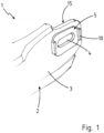
- FIG. 1 A section of a control arm 1 for a wheel suspension in a motor vehicle is shown.
- the control arm has a control arm body 2 made of a light metal material, in particular aluminum from the 5000 series to 7000 series.
- the control arm body 2 has two parallel side walls 3, of which only a wheel-carrier-side longitudinal section of a side wall 3 of the control arm body 2 is shown here.
- the eccentric bracket 5 is also in the Figures 2 to 5 shown.
- the eccentric holder 5 has a base plate 6 with an elongated hole opening 7.
- an anchor body 8 is formed, extending around the edge of the elongated hole opening 7.
- two eccentric stops 10 protruding from the base plate 6 are arranged.
- the anchor body 8 is formed in a ring shape surrounding the elongated hole opening 7.
- the anchor body 8 has a ring 11 extending around the elongated hole opening 7 and projecting from the rear side 12 of the base plate 6.
- the eccentric holder 5 with the base plate 6, the anchor body 8 and the eccentric stops 10 are formed in one piece from the same material.
- the eccentric bracket 5 is inserted with the anchor body 8 into the elongated hole 4 of the side wall 3 and press-fitted in the elongated hole 4.
- the outer contour of the anchor body 8 and the inner contour of the elongated hole 4 in the side wall 3 of the link body 2 are manufactured and geometrically coordinated in terms of dimensions so that a press fit is created by the press-fit on the circumferential joining surfaces.
- the eccentric stops 10 are formed by repositioned edge webs 13 on the outer circumference 14 of the base plate 6.
- the eccentric bracket 5 is made of a steel material and has a surface coating.
- the surface coating is typically a zinc or zinc flake coating.
- the press fit between the circumferential outer surface of the anchor body 8 and the inner surface of the elongated hole 4 in the side wall 3 creates a highly resilient, force-locking joint.
- the anchor body 8 can be widened internally from the elongated hole opening 7.
- the press fit can be supplemented by a form-locking joint.
- the anchor body 8 is flanged, clinched, or stamped at least in some areas on the side 15 of the side wall 3 opposite the base plate 6.
- the anchor body 8 can penetrate the elongated hole 4 in the side wall 3, at least in some areas, and is formed, for example, flanged, clinched, or stamped, on the side of the side wall 4 opposite the base plate 6.
- the base plate 6 has an essentially rectangular outer contour.
- the base plate 6 has a circular outer contour.
- the base plate 6 rests with its rear side 12 on the outside of the side wall 3 and protrudes from the outer surface of the side wall 3. It is also possible that a recess is provided in the side wall 3, which is configured to the outer geometry of the base plate 6 and in which the eccentric holder 5 with the base plate 6 lies.
Landscapes
- Engineering & Computer Science (AREA)
- Mechanical Engineering (AREA)
- Vehicle Body Suspensions (AREA)
- Steering Devices For Bicycles And Motorcycles (AREA)
Abstract
Description
- Die Erfindung betrifft einen Lenker für eine Radaufhängung in einem Kraftfahrzeug mit einem Lenkerkörper aus Leichtmetall, insbesondere Aluminium, welcher zwei zueinander parallele Seitenwände aufweist, wobei in zumindest einer Seitenwand ein Langloch für eine Exzenterhalterung vorgesehen ist.
- Lenker sind Komponenten der Radaufhängung eines Kraftfahrzeugs. Die Lenker müssen hohe radiale Kräfte, wie Brems- und Antriebskräfte, aufnehmen. Zusätzlich stützen die Lenker im Zusammenwirken mit anderen Fahrwerkskomponenten das Gewicht eines Kraftfahrzeugs ab.
- Über eine Exzenterverstelleinrichtung, die üblicherweise Exzenterelemente wie Exzenterscheiben oder Exzenterschrauben und/oder Steuerelemente aufweist, kann eine Ausrichtung eines Lenkers relativ zur radträgerseitigen Anbindung erfolgen. Auf diese Weise können Fahrzeugtoleranzen ausgeglichen sowie auch Spur und/oder Sturz der Räder eines Kraftfahrzeugs eingestellt werden. Die Exzenterverstelleinrichtung wirkt mit Langlöchern in den Seitenwänden des Lenkers zusammen an denen sie über eine Exzenterhalterung festgelegt werden kann.
- Zum Stand der Technik zählen Ausführungsformen von Lenkern mit Exzenterverstelleinrichtungen wie in der
US 2020/0361265 A1 , derDE 10 2019 020 874 A1 oder derKR 100907068 B1 - Um ein möglichst geringes Bauteilgewicht zu erreichen, werden die Lenkerkörper der Lenker häufig aus Leichtmetall bzw. einer Leichtmetalllegierung gefertigt, insbesondere aus Aluminium der 5000er Serie bis der 7000er Serie.
- Lenkerkörper aus Leichtmetall sind vorteilhaft im Gewicht. Allerdings sind die Bauteile auch anfällig, hinsichtlich Beschädigungen bzw. Verschleiß aufgrund der hohen im Betrieb einwirkenden Kräfte und Momente. Auch können die Lenkerkörper bei der Montage oder den Einstellvorgängen für den Sturz- und Sturzwinkel beschädigt werden. Dies gilt auch für Lenkerkörper aus anderen Leichtbauwerkstoffen, wie etwa Lenkerkörper aus Faserverbundkunststoffen.
- Der Erfindung liegt ausgehend vom Stand der Technik die Aufgabe zugrunde, einen leichtbauenden und funktional verbesserten Lenker aufzuzeigen, der insbesondere hinsichtlich des Verschleißschutzes im Bereich der Anbindung einer Exzenterverstelleinrichtung an bzw. in den Seitenwänden des Lenkerkörpers verbessert ist.
- Die Lösung dieser Aufgabe besteht in einem Lenker gemäß Anspruch 1.
- Vorteilhafte Ausgestaltungen und Weiterbildungen des erfindungsgemäßen Lenkers sind Gegenstand der abhängigen Ansprüche.
- Ausgestaltungen und Modifikationen von Merkmalen des erfindungsgemäßen Lenkers, die einzeln oder in Kombination die Erfindung in technisch vorteilhafter Weise ausgestalten und/oder weiterbilden, ergeben sich auch aus der Beschreibung und den beigefügten Zeichnungen.
- Ein erfindungsgemäßer Lenker für eine Radaufhängung in einem Kraftfahrzeug weist einen Lenkerkörper auf. Insbesondere besteht der Lenkerkörper aus Leichtmetall, vorzugsweise aus Aluminium bzw. einer Aluminiumlegierung der 5000er Serie bis 7000er Serie. Der Lenkerkörper besitzt zwei insbesondere zueinander parallele Seitenwände. In zumindest einer Seitenwand ist ein Langloch für eine Exzenterhalterung vorgesehen. Die Exzenterhalterung wirkt mit einer Exzenterverstelleinrichtung zusammen. Mittels der Exzentereinstellvorrichtung kann die relative Lage des Lenkers zur Radaufhängung bestimmt und Sturz- und Spurwinkel eingestellt werden.
- Die Exzenterhalterung ist am bzw. im Langloch einer Seitenwand festlegbar. Erfindungsgemäß weist die Exzenterhalterung eine Grundplatte mit einer Langlochöffnung auf, wobei rückseitig der Grundplatte ein randseitig der Langlochöffnung angeordneter Ankerkörper vorgesehen ist. Vorderseitig der Grundplatte sind zwei von der Grundplatte vorstehende Exzenteranschläge angeordnet. Die insbesondere randseitig der Grundplatte angeordneten Exzenteranschläge dienen als Steuerbahn für ein Stellelement der Exzenterverstelleinrichtung, wie insbesondere einer Exzenterscheibe. Erfindungsgemäß ist die Exzenterhalterung mit dem Ankerkörper im Langloch pressgefügt. Hierzu sind der Ankerkörper der Exzenterhalterung und das Langloch in der Seitenwand des Lenkers so hergestellt und konfigurativ aufeinander abgestimmt, dass nach dem Fügen an den Verbindungsstellen eine Presspassung entsteht. Hierdurch können Längs- und Querkräfte kraftschlüssig übertragen werden.
- Die erfindungsgemäße Exzenterhalterung übernimmt in einem Bauteil eine Schutzfunktion gegen Verschleiß oder Beschädigung beim Einstellen von Spur und Sturz und fungiert auch als Exzenterscheibenanschlag einer Exzenterverstelleinrichtung. Insbesondere wird der Bereich im bzw. um das Langloch in der Seitenwand des Lenkerkörpers vor Verschleiß und Beschädigungen geschützt.
- Die erfindungsgemäße Exzenterhalterung ist mit dem Ankerkörper in das Langloch in der Seitenwand des Lenkerkörpers eingepresst und pressgefügt. Die Fügung ist hoch stabil und belastbar. Kräfte werden zuverlässig aufgenommen und übertragen. Der aus Leichtmetall bestehende Lenkerkörper ist durch die Exzenterhalterung im Anbindungsbereich vor Verschleiß und Beschädigungen geschützt. Durch die Exzenterhalterung können zudem Materialkosten, Gewicht und Werkstoff selbst eingespart werden. Auch bauraumtechnisch ist die Exzenterhalterung vorteilhaft. Die Festlegung der Exzenterhalterung durch den Ankerkörper im Langloch ist bauraumoptimiert. Die Grundplatte der Exzenterhalterung liegt unmittelbar an der Seitenwand des Lenkerkörpers an. Der Ankerkörper stellt die hoch belastbare Fügung der Exzenterhalterung an der Seitenwand sicher, bildet einen mechanischen Schutz und stellt gleichzeitig die Langlochöffnung für die Exzenterverstelleinrichtung bereit. Durch die Integration der Exzenteranschläge in die Exzenterhaltung ist eine weitere Bauraumoptimierung möglich.
- Der Ankerkörper der Exzenterhalterung ist rückseitig der Grundplatte angeordnet. Rückseitig der Grundplatte bedeutet, dass der Ankerkörper auf der zur Seitenwand des Lenkerkörpers gerichteten Seite von der Grundplatte vorkragt. Der Ankerkörper ist vorzugsweise umlaufend um die Langlochöffnung ausgebildet. In dieser Ausgestaltung ist der Ankerkörper ringförmig gestaltet. Die Längswände bzw. -stege des Ankerkörpers verlaufen parallel und gehen jeweils durch halbkreisförmige Wandabschnitte des Ankerkörpers ineinander über. Vorzugsweise ist der Ankerkörper ein auf der Rückseite der Grundplatte umlaufend aus der Ebene der Grundplatte umgestellter langlochförmiger Kranz oder Ring.
- Grundsätzlich kann der Ankerkörper auch mehrere Ankerkörperabschnitte bzw. Ankerkörperelemente aufweisen, die randseitig der Langlochöffnung angeordnet sind.
- Der Ankerkörper ist dazu eingerichtet und bestimmt, in das Langloch einer Seitenwand des Lenkerkörpers eingeführt und in dem Langloch mit der Seitenwand pressgefügt zu werden, so dass die Exzenterhalterung zuverlässig an der Seitenwand des Lenkerkörpers festgelegt ist.
- Die Exzenterhalterung ist einstückig ausgeführt. Die Grundplatte, der Ankerkörper und die Exzenteranschläge sind werkstoffeinheitlich einstückig ausgebildet. Insbesondere besteht die Exzenterhalterung aus einem Stahlwerkstoff.
- Die Exzenteranschläge sind vorderseitig der Grundplatte angeordnet. Vorderseitig der Grundplatte bedeutet, dass die Exzenteranschläge auf der von der Seitenwand des Lenkerkörpers abgewandten Seite der Exzenterhalterung bzw. der Grundplatte vorgesehen sind. Die Exzenteranschläge sind aus dem Werkstoff der Exzenterhalterung in der Grundplatte ausgeformt. Die Exzenteranschläge können beispielsweise als Nocken oder Kragen an bzw. in der Grundplatte ausgebildet sein. Insbesondere sind die Exzenteranschläge durch umgestellte Randstege am äußeren Umfang der Grundplatte gebildet.
- Das Langloch in der Seitenwand des Lenkerkörpers und die Langlochöffnung in der Grundplatte der Exzenterhalterung sind gleichachsig zueinander ausgerichtet bzw. liegen auf einer gemeinsamen Mittelachse. Der Ankerkörper ist im Langloch der Seitenwand pressgefügt. Zwischen dem Innenumfang des Langlochs und dem Außenumfang des Ankerkörpers entsteht nach dem Fügen an den Verbindungsstellen eine Presspassung. Längs- und Querkräfte werden kraftschlüssig übertragen.
- Zur Erhöhung der Anpresskraft des Ankerkörpers im Langloch kann dieser mechanisch aufgeweitet werden. Dies erfolgt durch Aufbringen einer äußeren Kraft innenseitig der Langlochöffnung.
- Eine vorteilhafte Ausgestaltung sieht vor, dass zusätzlich eine Formschlussverbindung zwischen Ankerkörper und Seitenwand erzeugt wird. Hierzu wird der Ankerkörper zusätzlich umgeformt. Dies erfolgt vorzugsweise in dem der Ankerkörper von der Rückseite der Grundplatte her oder auf der der Grundplatte gegenüberliegenden Seite der Seitenwand umgebördelt, verclincht oder verprägt wird. Auch eine Durchsetzfügung ist denkbar.
- Insbesondere durchsetzt der Ankerkörper das Langloch in der Seitenwand zumindest bereichsweise und ist auf der der Grundplatte gegenüberliegenden Seite der Seitenwand umgeformt.
- Wie bereits erwähnt, besteht der Lenkerkörper vorzugsweise aus Leichtmetall oder einer Leichtmetalllegierung. Insbesondere besteht der Lenkerkörper aus Aluminium bzw. einem Aluminiumwerkstoff.
- Der Lenkerkörper kann aus einem Leichtbauwerkstoff bestehen, und zwar aus einem metallischen Leichtbauwerkstoff oder auch aus einem nicht metallischen Leichtbauwerkstoff, wie insbesondere einem Faserverbundkunststoff.
- Die Exzenterhaltung besteht aus einem höherfesterem Werkstoff als der Werkstoff des Lenkerkörpers.
- Die Exzenterhalterung besteht insbesondere aus Stahl.
- Eine weitere vorteilhafte Ausgestaltung sieht vor, dass die Exzenterhalterung eine Oberflächenbeschichtung aufweist. Für die Praxis ist insbesondere eine Zink- oder eine Zinklamellenbeschichtung besonders gut geeignet.
- Je nach Bauformvariante oder Modellreihe besitzt die Grundplatte eine rechteckförmige Außenkontur. Möglich ist auch, dass die Grundplatte eine kreis- oder ellipsenförmige Außenkontur aufweist.
- Denkbar ist auch, dass die Grundplatte in einer Aufnahme in der Seitenwand eingelassen ist. Die Seitenwand des Lenkerkörpers weist dann im Bereich um das Langloch eine an die Außenkontur der Grundplatte angepasste bzw. auf diese abgestimmte Vertiefung auf, in welcher die Grundplatte vorzugsweise bündig einliegt.
- Die Erfindung ist nachfolgend anhand von in den Zeichnungen dargestellten Ausführungsbeispielen näher beschrieben. Es zeigen:
- Figur 1
- in einer perspektivischen Darstellung einen Ausschnitt aus einem Lenker mit der Darstellung einer Seitenwand und einer mit der Seitenwand gefügten Exzenterhalterung;
- Figur 2
- die Exzenterhalterung in einer Seitenansicht;
- Figur 3
- die Exzenterhalterung in einer Draufsicht;
- Figur 4
- einen Schnitt durch die Darstellung der
Figur 2 ebenso wie derFigur 5 entlang der Linie A-A und - Figur 5
- eine weitere Ausführungsform einer Exzenterhalterung in einer Frontansicht.
- In der
Figur 1 ist ein Ausschnitt aus einem Lenker 1 für eine Radaufhängung in einem Kraftfahrzeug dargestellt. Der Lenker weist einen Lenkerkörper 2 aus einem Leichtmetallwerkstoff, insbesondere aus Aluminium der 5000er Serie bis 7000er Serie auf. Der Lenkerkörper 2 besitzt zwei zueinander parallele Seitenwände 3, von denen hier nur ein radträgerseitiger Längenabschnitt einer Seitenwand 3 des Lenkerkörpers 2 dargestellt ist. - In der Seitenwand 3 ist ein Langloch 4 für eine Exzenterhalterung 5 vorgesehen. Die Exzenterhalterung 5 ist ebenfalls in den
Figuren 2 bis 5 dargestellt. Die Exzenterhalterung 5 weist eine Grundplatte 6 mit einer Langlochöffnung 7 auf. Rückseitig der Grundplatte 6 ist ein sich randseitig um die Langlochöffnung 7 erstreckender Ankerkörper 8 ausgebildet. Vorderseitig bzw. auf der Vorderseite 9 der Grundplatte 6 sind zwei von der Grundplatte 6 vorstehende Exzenteranschläge 10 angeordnet. Der Ankerkörper 8 ist ringförmig umlaufend um die Langlochöffnung 7 ausgebildet. Der Ankerkörper 8 weist einen sich um die Langlochöffnung 7 erstreckenden Ring 11 auf, der von der Rückseite 12 der Grundplatte 6 vorkragt. - Die Exzenterhalterung 5 mit der Grundplatte 6, dem Ankerkörper 8 und den Exzenteranschlägen 10 sind werkstoffeinheitlich einstückig ausgebildet.
- Die Exzenterhalterung 5 ist mit dem Ankerkörper 8 in das Langloch 4 der Seitenwand 3 eingeführt und im Langloch 4 pressgefügt. Die Außenkontur des Ankerkörpers 8 und die Innenkontur des Langlochs 4 in der Seitenwand 3 des Lenkerkörpers 2 sind so hergestellt und von den Abmessungen geometrisch aufeinander abgestimmt, dass durch die Pressfügung an den umlaufenden Fügeflächen eine Presspassung entsteht.
- Die Exzenteranschläge 10 sind durch umgestellte Randstege 13 am äußeren Umfang 14 der Grundplatte 6 gebildet.
- Die Exzenterhalterung 5 besteht aus einem Stahlwerkstoff und ist mit einer Oberflächenbeschichtung versehen. Bei der Oberflächenbeschichtung handelt es sich insbesondere um eine Zink- oder Zinklamellenbeschichtung.
- Durch die Pressfügung zwischen der umlaufenden Außenfläche des Ankerkörpers 8 und der Innenfläche des Langlochs 4 in der Seitenwand 3 ist eine hoch belastbare kraftschlüssige Fügung erzeugt. Zur Erhöhung der Anpresskraft kann der Ankerkörper 8 innen von der Langlochöffnung 7 her aufgeweitet werden. Optional oder zusätzlich kann die Pressfügung durch eine Formschlussfügung ergänzt werden. Hierzu wird der Ankerkörper 8 auf der der Grundplatte 6 gegenüberliegenden Seite 15 der Seitenwand 3 zumindest bereichsweise umgebördelt, verclincht oder verprägt. Insbesondere kann der Ankerkörper 8 das Langloch 4 in der Seitenwand 3, zumindest bereichsweise durchsetzen und ist auf der der Grundplatte 6 gegenüberliegenden Seite der Seitenwand 4 umgeformt, beispielsweise umgebördelt, verclincht oder verprägt.
- In der Darstellung der
Figur 1 und2 erkannt man, dass die Grundplatte 6 eine im Wesentlichen rechteckförmige Außenkontur besitzt. - Die Exzenterhalterung 5, wie in der
Figur 5 dargestellt, entspricht funktional der zuvor beschriebenen. Die Grundplatte 6 besitzt eine kreisförmige Außenkontur. - Wie in der
Figur 1 zu erkennen, liegt die Grundplatte 6 mit ihrer Rückseite 12 außen an der Seitenwand 3 an und steht gegenüber der Außenfläche der Seitenwand 3 vor. Möglich ist es auch, dass in der Seitenwand 3 eine konfigurativ auf die Außengeometrie der Grundplatte 6 angepasste Ausnehmung vorgesehen ist, in welcher die Exzenterhalterung 5 mit der Grundplatte 6 einliegt. -
- 1 -
- Lenker
- 2 -
- Lenkerkörper
- 3 -
- Seitenwand
- 4 -
- Langloch in 3
- 5 -
- Exzenterhalterung
- 6 -
- Grundplatte
- 7 -
- Langlochöffnung
- 8 -
- Ankerkörper
- 9 -
- Vorderseite von 6
- 10-
- Exzenteranschlag
- 11 -
- Ring
- 12 -
- Rückseite von 6
- 13 -
- Randsteg
- 14 -
- Umfang
- 15 -
- Seite von 3
Claims (10)
- Lenker (1) für eine Radaufhängung in einem Kraftfahrzeug mit einem Lenkerkörper (2), welcher zwei Seitenwände (3) aufweist, wobei in zumindest einer Seitenwand (3) ein Langloch (4) für eine Exzenterhalterung (5) vorgesehen ist, dadurch gekennzeichnet, dass die Exzenterhalterung (5) eine Grundplatte (6) mit einer Langlochöffnung (7) aufweist, wobei rückseitig der Grundplatte (6) ein sich randseitig der Langlochöffnung (7) erstreckender Ankerkörper (8) vorgesehen ist und vorderseitig der Grundplatte (6) zwei von der Grundplatte (6) vorstehende Exzenteranschläge (10) angeordnet sind und die Exzenterhalterung (5) mit dem Ankerkörper (8) im Langloch (4) pressgefügt ist.
- Lenker (1) nach Anspruch 1, dadurch gekennzeichnet, dass der Ankerkörper (8) ringförmig umlaufend um die Langlochöffnung (7) ausgebildet ist.
- Lenker (1) nach Anspruch 1 oder 2, dadurch gekennzeichnet, dass die Exzenteranschläge (10) durch umgestellte Randstege (13) am äußeren Umfang (14) der Grundplatte (6) gebildet sind.
- Lenker (1) nach einem der Ansprüche 1 bis 3, dadurch gekennzeichnet, dass die Exzenterhalterung (5) mit der Grundplatte (6), dem Ankerkörper (8) und den Exzenteranschlägen (10) werkstoffeinheitlich einstückig ausgebildet ist.
- Lenker (1) nach einem der Ansprüche 1 bis 4, dadurch gekennzeichnet, dass der Ankerkörper (8) das Langloch (4) in der Seitenwand (3) zumindest bereichsweise durchsetzt und auf der der Grundplatte (6) gegenüber liegenden Seite (15) der Seitenwand (3) umgeformt ist.
- Lenker (1) nach einem der Ansprüche 1 bis 5, dadurch gekennzeichnet, dass der Lenkerkörper (8) aus Aluminium besteht.
- Lenker (1) nach einem der Ansprüche 1 bis 6, dadurch gekennzeichnet, dass die Exzenterhalterung (5) aus Stahl besteht.
- Lenker (1) nach einem der Ansprüche 1 bis 7, dadurch gekennzeichnet, dass die Exzenterhalterung (5) eine Oberflächenbeschichtung, insbesondere eine Zink- oder Zinklamellenschichtung, aufweist.
- Lenker (1) nach einem der Ansprüche 1 bis 8, dadurch gekennzeichnet, dass die Grundplatte (6) eine rechteckförmige Außenkontur aufweist.
- Lenker (1) nach einem der Ansprüche 1 bis 8, dadurch gekennzeichnet, dass die Grundplatte (6) eine kreis- oder ellipsenförmige Außenkontur aufweist.
Priority Applications (3)
| Application Number | Priority Date | Filing Date | Title |
|---|---|---|---|
| EP23202766.4A EP4538068B1 (de) | 2023-10-10 | 2023-10-10 | Lenker für eine radaufhängung in einem kraftfahrzeug |
| US18/911,188 US12454160B2 (en) | 2023-10-10 | 2024-10-09 | Control arm for a wheel suspension in a motor vehicle |
| CN202411398600.8A CN119795808A (zh) | 2023-10-10 | 2024-10-09 | 用于机动车中的车轮悬架的导杆 |
Applications Claiming Priority (1)
| Application Number | Priority Date | Filing Date | Title |
|---|---|---|---|
| EP23202766.4A EP4538068B1 (de) | 2023-10-10 | 2023-10-10 | Lenker für eine radaufhängung in einem kraftfahrzeug |
Publications (2)
| Publication Number | Publication Date |
|---|---|
| EP4538068A1 true EP4538068A1 (de) | 2025-04-16 |
| EP4538068B1 EP4538068B1 (de) | 2025-12-17 |
Family
ID=88315377
Family Applications (1)
| Application Number | Title | Priority Date | Filing Date |
|---|---|---|---|
| EP23202766.4A Active EP4538068B1 (de) | 2023-10-10 | 2023-10-10 | Lenker für eine radaufhängung in einem kraftfahrzeug |
Country Status (3)
| Country | Link |
|---|---|
| US (1) | US12454160B2 (de) |
| EP (1) | EP4538068B1 (de) |
| CN (1) | CN119795808A (de) |
Families Citing this family (1)
| Publication number | Priority date | Publication date | Assignee | Title |
|---|---|---|---|---|
| EP4674649A1 (de) * | 2024-07-03 | 2026-01-07 | Benteler Automobiltechnik GmbH | Lenker für eine radaufhängung in einem kraftfahrzeug |
Citations (6)
| Publication number | Priority date | Publication date | Assignee | Title |
|---|---|---|---|---|
| DE3921468C1 (en) * | 1989-06-30 | 1990-05-23 | Bayerische Motoren Werke Ag, 8000 Muenchen, De | Link for car wheel suspensions - has annular collars on two sheet metal parts, both collars surrounding bearing member |
| DE19721752A1 (de) * | 1997-05-24 | 1998-11-26 | Daimler Benz Ag | Vorrichtung zum Einstellen der Spur bei Rädern von Kraftfahrzeugen |
| KR20030018551A (ko) * | 2001-08-30 | 2003-03-06 | 현대자동차주식회사 | 차량의 토우조절장치 |
| KR100907068B1 (ko) | 2008-03-20 | 2009-07-09 | 현대자동차주식회사 | 자동차의 휠 얼라인먼트 조정유닛 |
| US20200361265A1 (en) | 2019-05-15 | 2020-11-19 | Marlin Crawler, Inc. | Reinforcement and protection braces for mounting structures of vehicle steering knuckle lower control arms |
| KR20220067769A (ko) * | 2020-11-18 | 2022-05-25 | 주식회사 동희산업 | 차량용 캠볼트 가이드 |
Family Cites Families (11)
| Publication number | Priority date | Publication date | Assignee | Title |
|---|---|---|---|---|
| US4733884A (en) * | 1986-08-04 | 1988-03-29 | Specialty Products Company | Camber adjustemnt device |
| US5052711A (en) * | 1990-05-18 | 1991-10-01 | A.O. Smith Corporation | Vehicle alignment and verification system |
| US5651561A (en) * | 1995-03-06 | 1997-07-29 | Ford Motor Company | Twin I-beam front suspension system |
| US6215624B1 (en) * | 1999-07-08 | 2001-04-10 | Magnecomp Corp. | Disk drive suspension mounting plate with torque enhancing feature |
| EP2357097B1 (de) * | 2010-02-17 | 2012-06-20 | Cie Automotive, S.A. | Lenker für einen Drehstab sowie Drehstab |
| DE102010043039A1 (de) * | 2010-10-28 | 2012-05-03 | Zf Friedrichshafen Ag | Verfahren zur Herstellung eines Fahrwerkbauteils |
| US9233589B1 (en) * | 2013-09-17 | 2016-01-12 | Northstar Manufacturing Co., Inc. | Cam bolt apparatus for suspension systems |
| EP2910454B1 (de) * | 2014-02-20 | 2016-08-17 | Autotech Engineering Deutschland GmbH | Fahrwerksbauteil mit Exzenterscheibenanschlag |
| US10508701B2 (en) * | 2017-04-06 | 2019-12-17 | The Pullman Company | Vehicle suspension bushing assembly and method of assembling the same |
| DE102019002874A1 (de) | 2019-04-17 | 2019-10-17 | Daimler Ag | Befestigung für einen Lenker einer Radaufhängung eines Kraftfahrzeugs sowie Kraftfahrzeug |
| EP4378718B1 (de) * | 2022-11-30 | 2025-10-01 | Benteler Automobiltechnik GmbH | Verfahren zur herstellung eines fahrwerkbauteils |
-
2023
- 2023-10-10 EP EP23202766.4A patent/EP4538068B1/de active Active
-
2024
- 2024-10-09 CN CN202411398600.8A patent/CN119795808A/zh active Pending
- 2024-10-09 US US18/911,188 patent/US12454160B2/en active Active
Patent Citations (6)
| Publication number | Priority date | Publication date | Assignee | Title |
|---|---|---|---|---|
| DE3921468C1 (en) * | 1989-06-30 | 1990-05-23 | Bayerische Motoren Werke Ag, 8000 Muenchen, De | Link for car wheel suspensions - has annular collars on two sheet metal parts, both collars surrounding bearing member |
| DE19721752A1 (de) * | 1997-05-24 | 1998-11-26 | Daimler Benz Ag | Vorrichtung zum Einstellen der Spur bei Rädern von Kraftfahrzeugen |
| KR20030018551A (ko) * | 2001-08-30 | 2003-03-06 | 현대자동차주식회사 | 차량의 토우조절장치 |
| KR100907068B1 (ko) | 2008-03-20 | 2009-07-09 | 현대자동차주식회사 | 자동차의 휠 얼라인먼트 조정유닛 |
| US20200361265A1 (en) | 2019-05-15 | 2020-11-19 | Marlin Crawler, Inc. | Reinforcement and protection braces for mounting structures of vehicle steering knuckle lower control arms |
| KR20220067769A (ko) * | 2020-11-18 | 2022-05-25 | 주식회사 동희산업 | 차량용 캠볼트 가이드 |
Also Published As
| Publication number | Publication date |
|---|---|
| CN119795808A (zh) | 2025-04-11 |
| US20250115087A1 (en) | 2025-04-10 |
| EP4538068B1 (de) | 2025-12-17 |
| US12454160B2 (en) | 2025-10-28 |
Similar Documents
| Publication | Publication Date | Title |
|---|---|---|
| EP2655127B1 (de) | Verfahren zum verbinden zweier bauteile eines fahrzeugsitzes | |
| DE2338957C3 (de) | Vorrichtung zum Befestigen eines Schutzdaches o.dgl. am Rahmen eines Erdbewegungs- o.ä. Fahrzeugs | |
| EP2093127B1 (de) | Lenkgetriebe mit Sensor | |
| EP2730456B1 (de) | Antrieb einer Sitzverstelleinrichtung für Kraftfahrzeuge | |
| DE102009044678B4 (de) | Verfahren und Vorrichtung zur Herstellung einer formschlüssigen Verbindung von unterschiedlichen topfförmigen Bauteilen einer Bremstrommel | |
| DE102014208003A1 (de) | Planetenträger für ein Planetengetriebe aus verschweißten Teilen | |
| DE102015000027A1 (de) | Lenksäule mit flexibel montierbarem Lagersitz | |
| DE102013108080A1 (de) | Querlenker für ein Kraftfahrzeug | |
| EP4538068B1 (de) | Lenker für eine radaufhängung in einem kraftfahrzeug | |
| EP3568257A1 (de) | Bauteilverbund von mindestens zwei bauteilen und ein verfahren zur herstelllung eines form- und/oder kraftschlüssig gefügten bauteilverbundes | |
| DE102010033714B3 (de) | Werkzeug zum Setzen von Vollstanznieten | |
| EP2265834B1 (de) | Käfig für ein wälzlager | |
| EP1935775B1 (de) | Kettenwerferbaugruppe für eine Fahrradschaltung | |
| DE102016123364A1 (de) | Klemmvorrichtung und Verfahren zur Herstellung von Klemmvorrichtungen | |
| DE9206848U1 (de) | Gelenk für Fahrwerksteile in einem Kraftfahrzeug | |
| EP3054182B1 (de) | Verfahren zur herstellung einer fügeverbindung zwischen einem gelenkgehäuse und einem anbindungsbauteil, sowie verfahrensgemäss hergestelltes fahrwerkbauteil | |
| DE102006057664A1 (de) | Stossdämpfer-beziehungsweise Schwenklagerhalterung für ein Kraftfahrzeug | |
| EP2330307B1 (de) | Lagerelement und Verfahren zu dessen Herstellung | |
| DE202010000258U1 (de) | Kugelgelenk, insbesondere für ein Fahrwerk eines Kraftfahrzeuges | |
| DE102013008328A1 (de) | Kupplungshalterung für eine Anhängekupplung | |
| EP4065394B1 (de) | Lenkersystem | |
| EP1559627B1 (de) | Fahrzeuglenkrad | |
| DE102018103076A1 (de) | Luftleiteinrichtung für ein Kraftfahrzeug | |
| EP0984187B1 (de) | Stützlager für Trommelbremsen | |
| DE20308895U1 (de) | Querträger zum Halten der Instrumententafel in einem Kraftfahrzeug |
Legal Events
| Date | Code | Title | Description |
|---|---|---|---|
| PUAI | Public reference made under article 153(3) epc to a published international application that has entered the european phase |
Free format text: ORIGINAL CODE: 0009012 |
|
| STAA | Information on the status of an ep patent application or granted ep patent |
Free format text: STATUS: REQUEST FOR EXAMINATION WAS MADE |
|
| 17P | Request for examination filed |
Effective date: 20250110 |
|
| AK | Designated contracting states |
Kind code of ref document: A1 Designated state(s): AL AT BE BG CH CY CZ DE DK EE ES FI FR GB GR HR HU IE IS IT LI LT LU LV MC ME MK MT NL NO PL PT RO RS SE SI SK SM TR |
|
| GRAP | Despatch of communication of intention to grant a patent |
Free format text: ORIGINAL CODE: EPIDOSNIGR1 |
|
| STAA | Information on the status of an ep patent application or granted ep patent |
Free format text: STATUS: GRANT OF PATENT IS INTENDED |
|
| INTG | Intention to grant announced |
Effective date: 20250821 |
|
| GRAS | Grant fee paid |
Free format text: ORIGINAL CODE: EPIDOSNIGR3 |
|
| GRAA | (expected) grant |
Free format text: ORIGINAL CODE: 0009210 |
|
| STAA | Information on the status of an ep patent application or granted ep patent |
Free format text: STATUS: THE PATENT HAS BEEN GRANTED |
|
| AK | Designated contracting states |
Kind code of ref document: B1 Designated state(s): AL AT BE BG CH CY CZ DE DK EE ES FI FR GB GR HR HU IE IS IT LI LT LU LV MC ME MK MT NL NO PL PT RO RS SE SI SK SM TR |
|
| REG | Reference to a national code |
Ref country code: CH Ref legal event code: F10 Free format text: ST27 STATUS EVENT CODE: U-0-0-F10-F00 (AS PROVIDED BY THE NATIONAL OFFICE) Effective date: 20251217 Ref country code: GB Ref legal event code: FG4D Free format text: NOT ENGLISH |
|
| REG | Reference to a national code |
Ref country code: DE Ref legal event code: R096 Ref document number: 502023002488 Country of ref document: DE |
|
| REG | Reference to a national code |
Ref country code: LT Ref legal event code: MG9D |
|
| PG25 | Lapsed in a contracting state [announced via postgrant information from national office to epo] |
Ref country code: HR Free format text: LAPSE BECAUSE OF FAILURE TO SUBMIT A TRANSLATION OF THE DESCRIPTION OR TO PAY THE FEE WITHIN THE PRESCRIBED TIME-LIMIT Effective date: 20251217 Ref country code: FI Free format text: LAPSE BECAUSE OF FAILURE TO SUBMIT A TRANSLATION OF THE DESCRIPTION OR TO PAY THE FEE WITHIN THE PRESCRIBED TIME-LIMIT Effective date: 20251217 |
|
| PG25 | Lapsed in a contracting state [announced via postgrant information from national office to epo] |
Ref country code: RS Free format text: LAPSE BECAUSE OF FAILURE TO SUBMIT A TRANSLATION OF THE DESCRIPTION OR TO PAY THE FEE WITHIN THE PRESCRIBED TIME-LIMIT Effective date: 20260317 |
|
| REG | Reference to a national code |
Ref country code: NL Ref legal event code: MP Effective date: 20251217 |
|
| PG25 | Lapsed in a contracting state [announced via postgrant information from national office to epo] |
Ref country code: LV Free format text: LAPSE BECAUSE OF FAILURE TO SUBMIT A TRANSLATION OF THE DESCRIPTION OR TO PAY THE FEE WITHIN THE PRESCRIBED TIME-LIMIT Effective date: 20251217 |
|
| PG25 | Lapsed in a contracting state [announced via postgrant information from national office to epo] |
Ref country code: BG Free format text: LAPSE BECAUSE OF FAILURE TO SUBMIT A TRANSLATION OF THE DESCRIPTION OR TO PAY THE FEE WITHIN THE PRESCRIBED TIME-LIMIT Effective date: 20251217 |
|
| PG25 | Lapsed in a contracting state [announced via postgrant information from national office to epo] |
Ref country code: NL Free format text: LAPSE BECAUSE OF FAILURE TO SUBMIT A TRANSLATION OF THE DESCRIPTION OR TO PAY THE FEE WITHIN THE PRESCRIBED TIME-LIMIT Effective date: 20251217 |
|
| PG25 | Lapsed in a contracting state [announced via postgrant information from national office to epo] |
Ref country code: LT Free format text: LAPSE BECAUSE OF FAILURE TO SUBMIT A TRANSLATION OF THE DESCRIPTION OR TO PAY THE FEE WITHIN THE PRESCRIBED TIME-LIMIT Effective date: 20251217 |
|
| PG25 | Lapsed in a contracting state [announced via postgrant information from national office to epo] |
Ref country code: SM Free format text: LAPSE BECAUSE OF FAILURE TO SUBMIT A TRANSLATION OF THE DESCRIPTION OR TO PAY THE FEE WITHIN THE PRESCRIBED TIME-LIMIT Effective date: 20251217 |
|
| PG25 | Lapsed in a contracting state [announced via postgrant information from national office to epo] |
Ref country code: ES Free format text: LAPSE BECAUSE OF FAILURE TO SUBMIT A TRANSLATION OF THE DESCRIPTION OR TO PAY THE FEE WITHIN THE PRESCRIBED TIME-LIMIT Effective date: 20251217 |
|
| PG25 | Lapsed in a contracting state [announced via postgrant information from national office to epo] |
Ref country code: PL Free format text: LAPSE BECAUSE OF FAILURE TO SUBMIT A TRANSLATION OF THE DESCRIPTION OR TO PAY THE FEE WITHIN THE PRESCRIBED TIME-LIMIT Effective date: 20251217 |
|
| PG25 | Lapsed in a contracting state [announced via postgrant information from national office to epo] |
Ref country code: IT Free format text: LAPSE BECAUSE OF FAILURE TO SUBMIT A TRANSLATION OF THE DESCRIPTION OR TO PAY THE FEE WITHIN THE PRESCRIBED TIME-LIMIT Effective date: 20251217 |
|
| PG25 | Lapsed in a contracting state [announced via postgrant information from national office to epo] |
Ref country code: EE Free format text: LAPSE BECAUSE OF FAILURE TO SUBMIT A TRANSLATION OF THE DESCRIPTION OR TO PAY THE FEE WITHIN THE PRESCRIBED TIME-LIMIT Effective date: 20251217 |
|
| PG25 | Lapsed in a contracting state [announced via postgrant information from national office to epo] |
Ref country code: PT Free format text: LAPSE BECAUSE OF FAILURE TO SUBMIT A TRANSLATION OF THE DESCRIPTION OR TO PAY THE FEE WITHIN THE PRESCRIBED TIME-LIMIT Effective date: 20260417 Ref country code: IS Free format text: LAPSE BECAUSE OF FAILURE TO SUBMIT A TRANSLATION OF THE DESCRIPTION OR TO PAY THE FEE WITHIN THE PRESCRIBED TIME-LIMIT Effective date: 20260417 |
|
| PG25 | Lapsed in a contracting state [announced via postgrant information from national office to epo] |
Ref country code: CZ Free format text: LAPSE BECAUSE OF FAILURE TO SUBMIT A TRANSLATION OF THE DESCRIPTION OR TO PAY THE FEE WITHIN THE PRESCRIBED TIME-LIMIT Effective date: 20251217 |
|
| PG25 | Lapsed in a contracting state [announced via postgrant information from national office to epo] |
Ref country code: SK Free format text: LAPSE BECAUSE OF FAILURE TO SUBMIT A TRANSLATION OF THE DESCRIPTION OR TO PAY THE FEE WITHIN THE PRESCRIBED TIME-LIMIT Effective date: 20251217 |
|
| PG25 | Lapsed in a contracting state [announced via postgrant information from national office to epo] |
Ref country code: SE Free format text: LAPSE BECAUSE OF FAILURE TO SUBMIT A TRANSLATION OF THE DESCRIPTION OR TO PAY THE FEE WITHIN THE PRESCRIBED TIME-LIMIT Effective date: 20251217 |