EP4538064A1 - Motorcycle tire - Google Patents
Motorcycle tire Download PDFInfo
- Publication number
- EP4538064A1 EP4538064A1 EP24198891.4A EP24198891A EP4538064A1 EP 4538064 A1 EP4538064 A1 EP 4538064A1 EP 24198891 A EP24198891 A EP 24198891A EP 4538064 A1 EP4538064 A1 EP 4538064A1
- Authority
- EP
- European Patent Office
- Prior art keywords
- groove
- tread
- tire
- edge
- shallow
- Prior art date
- Legal status (The legal status is an assumption and is not a legal conclusion. Google has not performed a legal analysis and makes no representation as to the accuracy of the status listed.)
- Pending
Links
Images




Classifications
-
- B—PERFORMING OPERATIONS; TRANSPORTING
- B60—VEHICLES IN GENERAL
- B60C—VEHICLE TYRES; TYRE INFLATION; TYRE CHANGING; CONNECTING VALVES TO INFLATABLE ELASTIC BODIES IN GENERAL; DEVICES OR ARRANGEMENTS RELATED TO TYRES
- B60C11/00—Tyre tread bands; Tread patterns; Anti-skid inserts
- B60C11/03—Tread patterns
- B60C11/0302—Tread patterns directional pattern, i.e. with main rolling direction
-
- B—PERFORMING OPERATIONS; TRANSPORTING
- B60—VEHICLES IN GENERAL
- B60C—VEHICLE TYRES; TYRE INFLATION; TYRE CHANGING; CONNECTING VALVES TO INFLATABLE ELASTIC BODIES IN GENERAL; DEVICES OR ARRANGEMENTS RELATED TO TYRES
- B60C11/00—Tyre tread bands; Tread patterns; Anti-skid inserts
- B60C11/03—Tread patterns
- B60C2011/0337—Tread patterns characterised by particular design features of the pattern
- B60C2011/0339—Grooves
- B60C2011/0341—Circumferential grooves
- B60C2011/0344—Circumferential grooves provided at the equatorial plane
-
- B—PERFORMING OPERATIONS; TRANSPORTING
- B60—VEHICLES IN GENERAL
- B60C—VEHICLE TYRES; TYRE INFLATION; TYRE CHANGING; CONNECTING VALVES TO INFLATABLE ELASTIC BODIES IN GENERAL; DEVICES OR ARRANGEMENTS RELATED TO TYRES
- B60C11/00—Tyre tread bands; Tread patterns; Anti-skid inserts
- B60C11/03—Tread patterns
- B60C2011/0337—Tread patterns characterised by particular design features of the pattern
- B60C2011/0339—Grooves
- B60C2011/0341—Circumferential grooves
- B60C2011/0346—Circumferential grooves with zigzag shape
-
- B—PERFORMING OPERATIONS; TRANSPORTING
- B60—VEHICLES IN GENERAL
- B60C—VEHICLE TYRES; TYRE INFLATION; TYRE CHANGING; CONNECTING VALVES TO INFLATABLE ELASTIC BODIES IN GENERAL; DEVICES OR ARRANGEMENTS RELATED TO TYRES
- B60C11/00—Tyre tread bands; Tread patterns; Anti-skid inserts
- B60C11/03—Tread patterns
- B60C2011/0337—Tread patterns characterised by particular design features of the pattern
- B60C2011/0339—Grooves
- B60C2011/0358—Lateral grooves, i.e. having an angle of 45 to 90 degees to the equatorial plane
- B60C2011/0365—Lateral grooves, i.e. having an angle of 45 to 90 degees to the equatorial plane characterised by width
-
- B—PERFORMING OPERATIONS; TRANSPORTING
- B60—VEHICLES IN GENERAL
- B60C—VEHICLE TYRES; TYRE INFLATION; TYRE CHANGING; CONNECTING VALVES TO INFLATABLE ELASTIC BODIES IN GENERAL; DEVICES OR ARRANGEMENTS RELATED TO TYRES
- B60C11/00—Tyre tread bands; Tread patterns; Anti-skid inserts
- B60C11/03—Tread patterns
- B60C2011/0337—Tread patterns characterised by particular design features of the pattern
- B60C2011/0339—Grooves
- B60C2011/0374—Slant grooves, i.e. having an angle of about 5 to 35 degrees to the equatorial plane
- B60C2011/0376—Slant grooves, i.e. having an angle of about 5 to 35 degrees to the equatorial plane characterised by width
-
- B—PERFORMING OPERATIONS; TRANSPORTING
- B60—VEHICLES IN GENERAL
- B60C—VEHICLE TYRES; TYRE INFLATION; TYRE CHANGING; CONNECTING VALVES TO INFLATABLE ELASTIC BODIES IN GENERAL; DEVICES OR ARRANGEMENTS RELATED TO TYRES
- B60C2200/00—Tyres specially adapted for particular applications
- B60C2200/10—Tyres specially adapted for particular applications for motorcycles, scooters or the like
Definitions
- the present invention relates to a motorcycle tire.
- Japanese Laid-Open Patent Publication No. 2022-161695 describes a motorcycle pneumatic tire including a tread portion that is provided with first grooves and second grooves having a smaller length in the tire circumferential direction than the first grooves.
- the first grooves each include a first inclined portion and a second inclined portion.
- the first inclined portion has a first end on a tread end side and extends so as to be inclined in a first tire circumferential direction
- the second inclined portion is connected to the first inclined portion and extends to a closed second end so as to be inclined in the first tire circumferential direction.
- the second grooves each extend so as to be inclined in the tire circumferential direction and have an inner end in the tire axial direction.
- the inner ends of the second grooves are located inward of the first ends and the second ends of the first grooves in the tire axial direction.
- Such a motorcycle pneumatic tire is expected to have an effect of improving drainage performance and wear resistance.
- the present disclosure has been made in view of the above-described problem, and an object of the present invention is to provide a motorcycle tire that can improve uneven wear resistance while maintaining wet performance.
- the present invention is directed to a motorcycle tire including a tread portion, wherein the tread portion is provided with a plurality of first inclined grooves which are open from a crown region including a tire equator to a first tread end, and each of the plurality of first inclined grooves includes a first portion in which a groove width decreases from the crown region toward the first tread end side, and a second portion in which the groove width increases toward the first tread end, up to the first tread end.
- the motorcycle tire of the present invention can improve uneven wear resistance while maintaining wet performance.
- FIG. 1 is a development view of a tread portion 2 of a motorcycle tire (hereinafter sometimes referred to as "tire") 1 showing one embodiment of the present invention.
- the present invention is used for tires for so-called commuter motorcycles, which are intended for use in urban use (for which comfort and safety are regarded as more important than speed). Such tires mainly have a large opportunity to run at small camber angles.
- the present invention is also suitably used for bias tires in which carcass cords of a carcass (not shown) extend at an angle of 20 to 60 degrees with respect to the tire circumferential direction.
- the tread portion 2 is provided with a crown region Cr including a tire equator C and a plurality of first inclined grooves 3 which are open from the crown region Cr to a first tread end T1.
- the tread portion 2 of the present embodiment is provided with a plurality of second inclined grooves 4 which are open from the crown region Cr to a second tread end T2.
- Each second inclined groove 4 of the present embodiment has a shape that is line-symmetrical with the first inclined groove 3, when the first inclined groove 3 is moved by an arbitrary distance in the tire circumferential direction and the tire equator C is used as the axis of symmetry. Therefore, in the present specification, the first inclined grooves 3 will be described as a representative, and for the second inclined grooves 4, the configuration different from that of the first inclined grooves 3 will be described.
- the first tread end T1 and the second tread end T2 are ends forming a maximum tread width.
- the first tread end T1 and the second tread end T2 are the outer ends of the tire 1 in the tire axial direction.
- the first tread end T1 and the second tread end T2 are both ends in the tire axial direction that are in contact with a flat surface when a standardized load is applied to the tire 1 in a standardized state and the tire 1 is brought into contact with the flat surface while being tilted to both sides in the tire axial direction at a camber angle of 30 degrees.
- the length along the tread surface 2a of the tread portion 2 between the first tread end T1 and the second tread end T2 is a tread development width TWe.
- 50% of the tread development width TWe is a tread development half width TW.
- the center in the tire axial direction between the first tread end T1 and the second tread end T2 is the tire equator C.
- dimensions and the like of components of the tire 1 are values measured in the standardized state.
- the "standardized load” is a load that is defined, in a standard system including a standard on which the tire 1 is based, by the standard for each tire, and is the "maximum load capacity" in the JATMA standard, the maximum value indicated in the table "TIRE LOAD LIMITS AT VARIOUS COLD INFLATION PRESSURES" in the TRA standard, or the "LOAD CAPACITY" in the ETRTO standard.
- the "standardized rim” is a rim that is defined for each tire by the standard, and is, for example, the “standard rim” in the JATMA standard, the “Design Rim” in the TRA standard, or the “Measuring Rim” in the ETRTO standard.
- the "standardized internal pressure” is an air pressure that is defined for each tire by the standard, and is the “maximum air pressure” in the JATMA standard, the maximum value indicated in the table “TIRE LOAD LIMITS AT VARIOUS COLD INFLATION PRESSURES" in the TRA standard, or the "INFLATION PRESSURE” in the ETRTO standard.
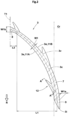
- FIG. 2 is a plan view of the first inclined groove 3.
- each of the plurality of first inclined grooves 3 includes a first portion 7 in which a groove width W1 decreases from the crown region Cr toward the first tread end T1 side, and a second portion 8 in which the groove width W1 increases toward the first tread end T1, up to the first tread end T1.
- the tread portion 2 has a profile (not shown) curved in an arc shape that is convex outward in the tire radial direction (not shown). Therefore, in the motorcycle tire 1, the amount of slippage during running tends to be larger on the first tread end T1 side with respect to the crown region Cr in the tread surface 2a.
- the first portion 7 in which the groove width W1 decreases toward the first tread end T1 side reduces the amount of slippage on the outer side in the tire axial direction, where the amount of slippage tends to be larger, and decreases the difference between the amounts of wear occurring at the tread surface 2a on both sides in the groove width direction of the first portion 7, thereby improving uneven wear resistance.
- a decrease in the groove width W1 of the first inclined groove 3 is suppressed in the region in contact with the road surface, so that wet performance can be maintained.
- the second portion 8 makes drainage from the first tread end T1 smooth, so that wet performance can be maintained. Therefore, the tire 1 of the present invention can improve uneven wear resistance while maintaining wet performance.
- the groove width W1 is a length in a direction orthogonal to a groove center line 3c of the first inclined groove 3.
- the groove width W1 is measured at a virtual groove edge 3v obtained by filling the smaller groove, the slit, or the like, at the location where the smaller groove, the slit, or the like is formed.
- FIG. 2 for convenience, the first portion 7 and the second portion 8 are shown by hatching with different directions.
- the virtual groove edge 3v is shown by an alternate long and two short dashes line.
- a length L1 in the tire axial direction of the first portion 7 is preferably not less than 50% and further preferably not less than 55% of the tread development half width TW, and is preferably not greater than 75% and further preferably not greater than 70% of the tread development half width TW. Since the length L1 of the first portion 7 is not less than 50% of the tread development half width TW, an effect of improving uneven wear resistance is exhibited. Since the length L1 of the first portion 7 is not greater than 75% of the tread development half width TW, an excessive decrease in flow of water in the first inclined groove 3 is suppressed.
- a maximum value W1a of the groove width W1 of the first portion 7 is preferably not less than 5% and further preferably not less than 7% of the tread development half width TW, and is preferably not greater than 15% and further preferably not greater than 13% of the tread development half width TW.
- a maximum value W1b of the groove width W1 of the second portion 8 is preferably not less than 80% and further preferably not less than 90% of the maximum value W1a of the groove width W1 of the first portion 7, and is preferably not greater than 120% and further preferably not greater than 110% of the maximum value W1a.
- the tread portion 2 of the present embodiment has a designated tire rotation direction R.
- the tread portion 2 comes into contact with a road surface from the lower side toward the upper side in the drawing.
- Each of the plurality of first inclined grooves 3 includes a pair of groove edges 3e extending in the longitudinal direction of the first inclined groove 3, and an inner end 3i in the tire axial direction.
- Each first inclined groove 3 includes a tapered portion 9 in which the pair of groove edges 3e of the first inclined groove 3 extend in a tapered shape toward the inner end 3i.
- Such a tapered portion 9 can smoothly guide a water film on the tread surface 2a into the first inclined groove 3.
- a length L3 in the tire circumferential direction of each tapered portion 9 is preferably not less than 5% and further preferably not less than 7% of a length La in the tire circumferential direction of the first inclined groove 3, and is preferably not greater than 13% and further preferably not greater than 11% of the length La.
- Each tapered portion 9 of the present embodiment is connected to the first portion 7.
- the tread portion 2 includes at least one shallow groove 12 connected to each first inclined groove 3.
- a shallow groove 12 removes a water film on the tread surface 2a to enhance contactability with a road surface, and also suppresses a decrease in the stiffness of the tread portion 2, so that wet performance is improved and uneven wear resistance is maintained high.
- the shallow groove 12 is formed with a groove depth d2 (shown in FIG. 4 ) smaller than a groove depth d1 of the first inclined groove 3.
- FIG. 3 is a plan view of the first inclined groove 3.
- the shallow groove 12 includes an opening 14 connected to the first inclined groove 3. Water in the shallow groove 12 flows through the opening 14 into the first inclined groove 3 and is drained to the outside of the tread surface 2a during running.
- the opening 14 is at a position overlapping the virtual groove edge 3v.
- the shallow groove 12 includes a pair of groove edges 12e connected to the groove edge 3e of the first inclined groove 3.
- at least one of the pair of groove edges 12e is formed in a curved shape that is convex on the trailing edge side in the tire rotation direction R.
- Each of the pair of groove edges 12e of the shallow groove 12 is connected to the groove edge 3e of the first inclined groove 3 by an arc 18, for example. Accordingly, the load applied to the portion where the first inclined groove 3 and the shallow groove 12 are connected is distributed, so that uneven wear resistance is improved.
- the opening 14 is formed between each arc 18.
- the tread surface 2a of the tread portion 2 includes an acute angle portion 20 sandwiched between one of the groove edges 3e of the first inclined groove 3 and one of the pair of groove edges 12e of the shallow groove 12.
- the tread surface 2a of the tread portion 2 includes an obtuse angle portion 21 sandwiched between one of the groove edges 3e of the first inclined groove 3 and one of the pair of groove edges 12e of the shallow groove 12.
- a radius of curvature r1 of the arc 18 is preferably not less than 0.5 mm and further preferably not less than 0.7 mm. Since the radius of curvature r1 is not less than 0.5 mm, uneven wear resistance can be improved.
- the upper limit value of the radius of curvature r1 of the arc 18 is not particularly limited, and is preferably not greater than 1.5 mm and further preferably not greater than 1.3 mm in consideration of appearance of the pattern design.
- a radius of curvature r2 of the arc 18 is preferably not less than 20 mm and further preferably not less than 30 mm, and is preferably not greater than 100 mm and further preferably not greater than 90 mm.
- the shallow groove 12 extends from the opening 14 toward the first tread end T1 side while extending toward the trailing edge side in the tire rotation direction R.
- the pair of groove edges 12e extend from the arc 18 toward the first tread end T1 side while extending toward the trailing edge side in the tire rotation direction R.
- Such a shallow groove 12 relatively decreases the amount of slippage during running, thereby improving uneven wear resistance.
- Such a shallow groove 12 also distributes and reduces the load generated around the first inclined groove 3, thereby improving uneven wear resistance.
- the shallow groove 12 has one end 12t terminating at the position on the most trailing edge side in the tire rotation direction R.
- the pair of groove edges 12e include a first groove edge 12a located on the trailing edge side in the tire rotation direction R, and a second groove edge 12b located on the leading edge side in the tire rotation direction R.
- the first groove edge 12a defines the acute angle portion 20.
- the acute angle portion 20 is located on the trailing edge side in the tire rotation direction R with respect to the shallow groove 12.
- the second groove edge 12b defines the obtuse angle portion 21.
- the obtuse angle portion 21 is located on the leading edge side in the tire rotation direction R with respect to the shallow groove 12. Accordingly, the above-described effect of relatively decreasing the amount of slippage during running is effectively exhibited.
- the shallow groove 12 has a groove width W2 parallel to an opening width Wa of the opening 14.
- the groove width W2 of the shallow groove 12 decreases with increasing distance from the first inclined groove 3. Accordingly, an excessive decrease in the stiffness of the tread portion 2 (tread surface 2a) is suppressed.
- the "increasing distance from the first inclined groove 3" is in a direction orthogonal to the opening width Wa.
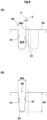
- FIG. 4 is a cross-sectional view taken along a line A-A in FIG. 2 .
- the groove depth d2 of the shallow groove 12 decreases with increasing distance from the first inclined groove 3. Accordingly, an excessive decrease in the stiffness of the tread surface 2a is suppressed.
- the groove depth d2 of the shallow groove 12 is maximum at the opening 14 and minimum at the one end 12t.
- a maximum groove depth d2a of the shallow groove 12 is preferably not less than 0.3 times and further preferably not less than 0.4 times the groove depth d1 of the first inclined groove 3 at the position of the opening 14, and is preferably not greater than 0.7 times and further preferably not greater than 0.6 times the groove depth d1 of the first inclined groove 3. Since the maximum groove depth d2a of the shallow groove 12 is not less than 0.3 times the groove depth d1 of the first inclined groove 3, an effect of improving wet performance is exhibited. Since the maximum groove depth d2a of the shallow groove 12 is not greater than 0.7 times the groove depth d1 of the first inclined groove 3, an excessive decrease in the stiffness of the tread portion 2 is suppressed.
- the opening width Wa is preferably not less than 1.0 times and further preferably not less than 1.5 times a groove width W1d of the first inclined groove 3 at the position of the opening 14 (region A3), and is preferably not greater than 4.0 times and further preferably not greater than 3.5 times the groove width W1d of the first inclined groove 3. Since the opening width Wa is not less than 1.0 times the groove width W1d of the first inclined groove 3, an effect of improving wet performance is exhibited. Since the opening width Wa is not greater than 4.0 times the groove width W1d of the first inclined groove 3, an excessive decrease in the stiffness of the tread portion 2 is suppressed.
- the shallow groove 12 includes a first shallow groove 12A connected to the leading-edge-side inclined groove edge 11A, and a second shallow groove 12B connected to the trailing-edge-side inclined groove edge 11B.
- the first shallow groove 12A is located on the inner end 3i side (leading edge side in the tire rotation direction R) with respect to the second shallow groove 12B.
- the second shallow groove 12B includes an inner second shallow groove 23 located at a position overlapping the first shallow groove 12A in the tire axial direction, and an outer second shallow groove 24 located on the first tread end T1 side with respect to the inner second shallow groove 23.
- the outer second shallow groove 24 is located over the first portion 7 and the second portion 8.
- each shallow groove 12 is located on the first tread end T1 side with respect to the crown region Cr.
- One end 24e on the trailing edge side in the tire rotation direction R of the outer second shallow groove 24 is located on the trailing edge side in the tire rotation direction R with respect to one end 3b on the trailing edge side in the tire rotation direction R of the first inclined groove 3.
- Such an outer second shallow groove 24 serves to collect a larger amount of a water film on the tread surface 2a, in the first inclined groove 3.
- FIG. 5 is a plan view of the tread portion 2. As shown in FIG. 5 , the tread portion 2 of the present embodiment is further provided with a circumferential groove 26 extending continuously in the tire circumferential direction and small inclined grooves 40 having a smaller length than the first inclined groove 3.
- FIG. 6 is a plan view of the circumferential groove 26.
- the circumferential groove 26 extends in a wavy shape, for example.
- Such a circumferential groove 26 has a larger groove volume than, for example, a circumferential groove (not shown) extending in a straight manner in the tire circumferential direction, thereby reducing the amount of water splashing.
- the circumferential groove 26 extends in a sinusoidal shape.
- Such a circumferential groove 26 makes the flow of water in the circumferential groove 26 smoother than, for example, a circumferential groove extending in a zigzag or pseudo-sinusoidal shape, thereby reducing the amount of water splashing upon contact with a wet road surface without impairing drainage performance from the tread surface 2a. Accordingly, running performance on a wet road surface is improved.
- the sinusoidal shape is not only a sinusoidal wave, but also includes a shape formed by waves having a plurality of different wavelengths and/or a plurality of different amplitudes.
- the ratio ( ⁇ /A) of an amplitude ⁇ to a half wavelength A (shown in FIG. 5 ) of the circumferential groove 26 is preferably not less than 0.04 and further preferably not less than 0.06 and is preferably not greater than 0.12 and further preferably not greater than 0.10. Since the ratio ( ⁇ /A) is not greater than 0.12, water splashing upon contact with a wet road surface can be greatly angled to the right and left sides with respect to the traveling direction. Since the ratio ( ⁇ /A) is not less than 0.04, the flow of water in the circumferential groove 26 is smoother, so that the water splashing can be suppressed.
- the amplitude ⁇ and the half wavelength A are specified by a groove center line 26c of the circumferential groove 26.
- the groove center line 26c is specified by a location on the tread surface 2a in the tire radial direction.
- the circumferential groove 26 is located, for example, in the crown region Cr.
- the circumferential groove 26 is preferably located on the tire equator C.
- a center line 26k of the amplitude of the circumferential groove 26 is located on the tire equator C. Accordingly, the water splashing during straight running, which is running at a relatively high speed, can be suppressed.
- the circumferential groove 26 includes a plurality of first inclined portions 28 inclined in a first direction with respect to the tire circumferential direction, and a plurality of second inclined portions 29 inclined in a direction opposite to the first direction.
- the first inclined portions 28 and the second inclined portions 29 angle water splashing to the right and left sides with respect to the traveling direction upon contact with a wet road surface, thereby reducing forward water splashing.
- the circumferential groove 26 has a basic performance of reducing forward water splashing.
- the first inclined portions 28 are inclined toward the upper right side.
- the second inclined portions 29 are inclined toward the upper left side.
- the first inclined portions 28 may be inclined toward the upper left side
- the second inclined portions 29 may be inclined toward the upper right side.
- the circumferential groove 26 further includes connection portions 30 connecting the first inclined portions 28 and the second inclined portions 29 adjacent to each other in the tire circumferential direction.
- the connection portions 30 include first connection portions 30A located on the first tread end T1 side, and second connection portions 30B located on the second tread end T2 side.
- the first connection portions 30A are located, for example, on the first tread end T1 side with respect to the tire equator C.
- the second connection portions 30B are located, for example, on the second tread end T2 side with respect to the tire equator C.
- the circumferential groove 26 includes a pair of groove walls 31 extending inward in the tire radial direction from the tread surface 2a.
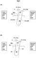
- FIG. 7(A) is a cross-sectional view taken along a line B-B in FIG. 6 .
- FIG. 7(A) shows a groove cross-section in the tire meridional direction of each of the plurality of first inclined portions 28.
- each of the pair of groove walls 31 is inclined toward the first tread end T1 side with respect to a tread normal line n at a groove edge 26e while extending inward in the tire radial direction.
- FIG. 7(B) is a cross-sectional view taken along a line C-C in FIG. 6 .
- each of the pair of groove walls 31 is inclined toward the second tread end T2 side with respect to a tread normal line n at the groove edge 26e while extending inward in the tire radial direction. Owing to this inclination, water splashing during running on a wet road surface can be further distributed to the right and left sides.
- the first inclined portions 28 and the second inclined portions 29 each have a portion whose inclination angle with respect to the tire circumferential direction increases as the wear of the tread portion 2 progresses. Accordingly, in the end stage of wear in which the groove volume becomes small, water splashing is caused at a larger angle with respect to the traveling direction, so that forward water splashing can be suppressed over a long period of time.
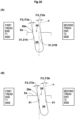
- FIG. 8(A) is a cross-sectional view taken along a line D-D in FIG. 6 .
- FIG. 8(A) shows a groove cross-section in the tire meridional direction of each of the multiple connection portions 30.
- FIG. 8(A) shows a groove cross-section in the tire meridional direction of the first connection portion 30A.
- the pair of groove walls 31 extend at an angle ⁇ of 0 degrees with respect to a tread normal line n at the groove edge 26e.
- the pair of groove walls 31 may extend inward in the tire radial direction in a tapered shape (shown in FIG. 8(B) ).
- Such a connection portion 30 makes the flow of water in the first inclined portion 28 and the second inclined portion 29 smooth, thereby reducing the amount of the water splashing.
- FIG. 9(A) is a cross-sectional view taken along a line E-E in FIG. 6 .
- FIG. 9(B) is a cross-sectional view taken along a line F-F in FIG. 6 .
- FIG. 9(A) and FIG. 9(B) each show a groove cross-section in the tire meridional direction of each of the plurality of first inclined portions 28.
- the cross-sections shown in FIG. 9(A) and FIG. 9(B) are cross-sections on both end 28e (connection portion 30) sides of the first inclined portion 28 with respect to an intermediate portion 28c (shown in FIG. 6 ) in the longitudinal direction of the first inclined portion 28.
- FIG. 10(A) is a cross-sectional view taken along a line G-G in FIG.
- FIG. 10(B) is a cross-sectional view taken along a line H-H in FIG. 6 .
- FIG. 10(A) and FIG. 10(B) each show a groove cross-section in the tire meridional direction of each of the plurality of second inclined portions 29.
- the cross-sections shown in FIG. 10(A) and FIG. 10(B) are cross-sections on both end 29e (connection portion 30) sides of the second inclined portion 29 with respect to an intermediate portion 29c (shown in FIG. 6 ) in the longitudinal direction of the second inclined portion 29.
- an angle ⁇ 1 (shown in FIG. 7(A) , FIG. 9(A), and FIG. 9(B) ) of each of the pair of groove walls 31 with respect to the tread normal line n is, for example, the same from one end 28e (connection portion 30) side through the intermediate portion 28c to another end 28e (connection portion 30) side of the first inclined portion 28.
- an angle ⁇ 2 shown in FIG. 7(B) , FIG. 10(A), and FIG.
- first inclined portions 28 and second inclined portions 29 decrease the change in the inclination angles of the first inclined portions 28 and the second inclined portions 29 with respect to the tire circumferential direction in the end stage of wear to allow more water to be captured in the circumferential groove 26, thereby suppressing water splashing.
- each first inclined portion 28 refers to a region, within 1/4 of a length Lx in the longitudinal direction of the first inclined portion 28, centered at the midpoint in the tire circumferential direction of the first inclined portion 28.
- the intermediate portion 29c of each second inclined portion 29 is also defined in the same manner.
- the angle ⁇ 1 of each of the pair of groove walls 31 with respect to the tread normal line n is maximum at least at the intermediate portion 28c in the longitudinal direction of each of the plurality of first inclined portions 28.
- the angle ⁇ 2 of each of the pair of groove walls 31 with respect to the tread normal line n is maximum at least at the intermediate portion 29c in the longitudinal direction of each of the plurality of second inclined portions 29.
- Such intermediate portions 28c and 29c effectively exhibit the above-described effects.
- the angle ⁇ of each of the pair of groove walls 31 with respect to the tread normal line n changes between the cross-section along the line G-G and the cross-section along the line F-F adjacent to each other in the tire circumferential direction across the first connection portion 30A.
- the angle ⁇ of each of the pair of groove walls 31 with respect to the tread normal line n changes between the cross-section along the line E-E and the cross-section along the line H-H adjacent to each other in the tire circumferential direction across the second connection portion 30B.
- the maximum values of the angles ⁇ 1 and ⁇ 2 of each of the pair of groove walls 31 with respect to the tread normal line n are preferably not less than 5 degrees and further preferably not less than 7 degrees, and are preferably not greater than 15 degrees and further preferably not greater than 13 degrees. Since the maximum values of the angles ⁇ 1 and ⁇ 2 are not less than 5 degrees, water splashing can be caused at a greater angle with respect to the traveling direction in the end stage of wear. Since the maximum values of the angles ⁇ 1 and ⁇ 2 are not greater than 15 degrees, the change in the stiffness of the tread portion 2 around the circumferential groove 26 can be maintained small. In addition, since the maximum values of the angles ⁇ 1 and ⁇ 2 are not greater than 15 degrees, damage caused by pulling from a mold (not shown) for producing the tire 1 is suppressed.
- each first connection portion 30A is located, for example, on the tire equator C side with respect to the inner end 3i of the first inclined groove 3.
- the respective inner ends 3i of the plurality of first inclined grooves 3 are located on the first tread end T1 side with respect to the multiple first connection portions 30A.
- each second connection portion 30B is located, for example, on the tire equator C side with respect to an inner end 4i of the second inclined groove 4.
- the respective inner ends 4i of the plurality of second inclined grooves 4 are located on the second tread end T2 side with respect to the multiple second connection portions 30B.
- each first inclined portion 28 is adjacent to the inner end 3i of the first inclined groove 3.
- the respective inner ends 3i of the plurality of first inclined grooves 3 are located adjacent to the plurality of first inclined portions 28 in the tire axial direction.
- each inner end 3i is adjacent to the first inclined portion 28 rather than the second inclined portion 29.
- the pair of groove walls 31 of each first inclined portion 28 are inclined toward the first tread end T1 side.
- each second inclined portion 29 is adjacent to the inner end 4i of the second inclined groove 4.
- the respective inner ends 4i of the plurality of second inclined grooves 4 are located adjacent to the plurality of second inclined portions 29 in the tire axial direction.
- each inner end 4i is adjacent to the second inclined portion 29 rather than the first inclined portion 28.
- the pair of groove walls 31 of each second inclined portion 29 are inclined toward the second tread end T2 side while extending inward in the tire radial direction. Accordingly, as described above, the difference between the amounts of wear of the tread surface 2a on both sides of the second inclined portion 29 is reduced.
- the pair of groove walls 31 of the circumferential groove 26 include a first groove wall 31A on the first tread end T1 side and a second groove wall 31B on the second tread end T2 side.
- an angle ⁇ 1a of the first groove wall 31A with respect to the tread normal line n is preferably the same (same absolute value) as an angle ⁇ 1b of the second groove wall 31B with respect to the tread normal line n.
- FIG. 7(B) FIG. 10(A), and FIG.
- each second inclined portion 29 the fact that the angles are the same includes not only the case where the absolute value
- the first groove wall 31A and the tread surface 2a form an acute angle
- the second groove wall 31B and the tread surface 2a form an obtuse angle.
- the first groove wall 31A and the tread surface 2a form an obtuse angle
- the second groove wall 31B and the tread surface 2a form an acute angle.
- the circumferential groove 26 further includes a groove bottom portion 33 connected to the pair of groove walls 31.
- the pair of groove walls 31 extend in a straight manner, for example.
- the straight manner includes not only extending straight in the groove cross-section in the tire meridional direction, but also extending in an arc having a radius of curvature of 100 mm or more.
- the groove bottom portion 33 includes a groove bottom having a maximum groove depth, and is formed in an arc shape in the present embodiment. Such a groove bottom portion 33 makes the flow of water in the circumferential groove 26 smoother, and also distributes stress generated at the groove bottom, thereby suppressing occurrence of groove bottom cracking.
- the arc shape includes not only an arc having a single radius of curvature, but also a shape formed by an arc forming the groove bottom and a pair of arcs connected to both ends of this arc and having a smaller radius of curvature than the arc at the groove bottom (not shown).
- the arc forming the groove bottom may be straight.
- a groove width W3 of such a circumferential groove 26 is, for example, preferably not less than 2% and further preferably not less than 3% of the tread development half width TW, and is preferably not greater than 7% and further preferably not greater than 6% of the tread development half width TW.
- a groove depth d3 of the circumferential groove 26 is, for example, preferably not less than 1.1 times and further preferably not less than 1.5 times the groove width W3, and is preferably not greater than 3.5 times and further preferably not greater than 3.0 times the groove width W3.
- the small inclined grooves 40 include a plurality of first small inclined grooves 40A extending from the crown region Cr toward the first tread end T1 side, and a plurality of second small inclined grooves 40B extending from the crown region Cr toward the second tread end T2 side.
- the second small inclined grooves 40B each have the same shape as a shape obtained by inverting the first small inclined groove 40A at the tire equator C (line-symmetrical shape). Therefore, in the present specification, the first small inclined grooves 40A will be described as a representative, and for the second small inclined grooves 40B, the configuration different from that of the first small inclined grooves 40A will be described.
- Each first small inclined groove 40A has an inner end 40i located on the first tread end T1 side with respect to the inner end 3i of the first inclined groove 3, and is open at the first tread end T1.
- the first small inclined groove 40A extends toward the first tread end T1 side while extending toward the trailing edge side in the tire rotation direction R.
- FIG. 11 is a plan view of the first small inclined groove 40A.
- the first small inclined groove 40A has, for example, a pair of groove edges 40e extending from the inner end 40i to the first tread end T1.
- the pair of groove edges 40e include a leading-edge-side small groove edge 43 located on the leading edge side in the tire rotation direction R, and a trailing-edge-side small groove edge 44 located on the trailing edge side in the tire rotation direction R.
- the first small inclined groove 40A includes a first portion 48 in which a groove width W4 decreases toward the first tread end T1 side, and a second portion 49 in which the groove width W4 increases toward the first tread end T1, up to the first tread end T1.
- the first portion 48 reduces the amount of slippage on the outer side in the tire axial direction, where the amount of slippage tends to be larger, and decreases the difference between the amounts of wear occurring on both sides in the groove width direction of the first portion 48, thereby improving uneven wear resistance.
- the second portion 49 makes drainage from the first tread end T1 smooth, so that wet performance can be maintained.
- test tires were mounted to the front and rear wheels of a motorcycle.
- a test rider rode this motorcycle on test courses having a wet road surface and a dry asphalt road surface. Both performances were evaluated based on sensory evaluation of the test rider, and are indicated as scores with the score of Comparative Example 1 as 100. The higher the value is, the better both performances are.
- the occurrence state of uneven wear was visually evaluated by a tester. The evaluation is indicated as a score with the occurrence state of uneven wear of Comparative Example 1 as 100.
- life performance the estimated life of each tire was indexed from the groove depth of the circumferential groove after the end of the ride. The higher the value is, the better both performances are.
- each first inclined groove is inclined toward the first tread end side while extending toward the trailing edge side in the tire rotation direction
- “B” means that each first inclined groove is inclined toward the tire equator side while extending toward the trailing edge side in the tire rotation direction.
- each shallow groove has the shape in FIG. 3
- “D” means that the portion including the one end 12t of the shallow groove is an arc.
- each shallow groove has the shape in FIG. 4
- “F” means the groove depth d2 of the shallow groove is the same from the opening 14 to the one end 12t.
- Example 7 the acute angle portion has an arc having a radius of curvature of 0.5 mm, and in Example 8, the acute angle portion has an arc having a radius of curvature of 1.5 mm.
- Table 1 Com. Ex. 1 Ex. 1 Ex. 2 Ex. 3 Ex. 4 Ex. 5 Ex. 6 Ex. 7 Ex. 8 Ex.
- the present invention includes the following aspects.
- a motorcycle tire including a tread portion, wherein
- a maximum groove depth of the shallow groove is 0.3 to 0.7 times a groove depth of the first inclined groove at a position of the opening.
- the opening width is 1 to 4 times the groove width of the first inclined groove at a position of the opening.
Landscapes
- Engineering & Computer Science (AREA)
- Mechanical Engineering (AREA)
- Tires In General (AREA)
Abstract
Description
- The present invention relates to a motorcycle tire.
-
Japanese Laid-Open Patent Publication No. 2022-161695 - In recent years, it has been known to increase the groove widths of grooves in order to improve wet performance. However, merely increasing the groove widths of the grooves causes a problem that the amounts of slippage on tread surfaces respectively including a pair of groove edges extending in the longitudinal direction of the grooves are different and a large difference between the amounts of wear of both tread surfaces occurs (i.e., uneven wear occurs).
- The present disclosure has been made in view of the above-described problem, and an object of the present invention is to provide a motorcycle tire that can improve uneven wear resistance while maintaining wet performance.
- The present invention is directed to a motorcycle tire including a tread portion, wherein the tread portion is provided with a plurality of first inclined grooves which are open from a crown region including a tire equator to a first tread end, and each of the plurality of first inclined grooves includes a first portion in which a groove width decreases from the crown region toward the first tread end side, and a second portion in which the groove width increases toward the first tread end, up to the first tread end.
- As a result of adopting the above configuration, the motorcycle tire of the present invention can improve uneven wear resistance while maintaining wet performance.
-
-
FIG. 1 is a development view of a tread portion of a motorcycle tire showing one embodiment of the present invention; -
FIG. 2 is a plan view of a first inclined groove; -
FIG. 3 is a plan view of the first inclined groove; -
FIG. 4 is a cross-sectional view taken along a line A-A inFIG. 2 ; -
FIG. 5 is a development view of the tread portion of the embodiment; -
FIG. 6 is a plan view of a circumferential groove; -
FIG. 7(A) is a cross-sectional view taken along a line B-B inFIG. 6 ; -
FIG. 7(B) is a cross-sectional view taken along a line C-C inFIG. 6 ; -
FIG. 8(A) is a cross-sectional view taken along a line D-D inFIG. 6 ; -
FIG. 8(B) is a cross-sectional view of another embodiment ofFIG. 8A ; -
FIG. 9(A) is a cross-sectional view taken along a line E-E inFIG. 6 ; -
FIG. 9(B) is a cross-sectional view taken along a line F-F inFIG. 6 ; -
FIG. 10(A) is a cross-sectional view taken along a line G-G inFIG. 6 ; -
FIG. 10(B) is a cross-sectional view taken along a line H-H inFIG. 6 ; and -
FIG. 11 is a plan view of a first small inclined groove. - Hereinafter, an embodiment of the present invention will be described with reference to the drawings. The drawings contain exaggerated expressions and expressions that differ from the dimensional ratio of the actual structure in order to help the understanding of the present invention. In addition, when there are a plurality of embodiments, the same or common elements are denoted by the same reference characters throughout the description, and the redundant description thereof is omitted.
-
FIG. 1 is a development view of atread portion 2 of a motorcycle tire (hereinafter sometimes referred to as "tire") 1 showing one embodiment of the present invention. The present invention is used for tires for so-called commuter motorcycles, which are intended for use in urban use (for which comfort and safety are regarded as more important than speed). Such tires mainly have a large opportunity to run at small camber angles. The present invention is also suitably used for bias tires in which carcass cords of a carcass (not shown) extend at an angle of 20 to 60 degrees with respect to the tire circumferential direction. - As shown in
FIG. 1 , thetread portion 2 is provided with a crown region Cr including a tire equator C and a plurality of firstinclined grooves 3 which are open from the crown region Cr to a first tread end T1. In addition, thetread portion 2 of the present embodiment is provided with a plurality of secondinclined grooves 4 which are open from the crown region Cr to a second tread end T2. Each secondinclined groove 4 of the present embodiment has a shape that is line-symmetrical with the firstinclined groove 3, when the firstinclined groove 3 is moved by an arbitrary distance in the tire circumferential direction and the tire equator C is used as the axis of symmetry. Therefore, in the present specification, the firstinclined grooves 3 will be described as a representative, and for the secondinclined grooves 4, the configuration different from that of the firstinclined grooves 3 will be described. - The first tread end T1 and the second tread end T2 are ends forming a maximum tread width. In the case where the
tire 1 has a maximum tread width equal to the total width (maximum width) of thetire 1, the first tread end T1 and the second tread end T2 are the outer ends of thetire 1 in the tire axial direction. In the case where thetire 1 has a maximum tread width smaller than the total width of thetire 1, the first tread end T1 and the second tread end T2 are both ends in the tire axial direction that are in contact with a flat surface when a standardized load is applied to thetire 1 in a standardized state and thetire 1 is brought into contact with the flat surface while being tilted to both sides in the tire axial direction at a camber angle of 30 degrees. The length along thetread surface 2a of thetread portion 2 between the first tread end T1 and the second tread end T2 is a tread development width TWe. In addition, 50% of the tread development width TWe is a tread development half width TW. The center in the tire axial direction between the first tread end T1 and the second tread end T2 is the tire equator C. In the present specification, unless otherwise specified, dimensions and the like of components of thetire 1 are values measured in the standardized state. - In the present embodiment, the crown region Cr is a region that is in contact with a flat surface when the standardized load is applied to the
tire 1 in the standardized state and thetire 1 is brought into contact with the flat surface at a camber angle of 0 degrees, and is a region that is in contact with the ground mainly during straight running. The "standardized state" is a state where thetire 1 is fitted on a standardized rim (not shown) and adjusted to have a standardized internal pressure and no load is applied to thetire 1. The "standardized load" is a load that is defined, in a standard system including a standard on which thetire 1 is based, by the standard for each tire, and is the "maximum load capacity" in the JATMA standard, the maximum value indicated in the table "TIRE LOAD LIMITS AT VARIOUS COLD INFLATION PRESSURES" in the TRA standard, or the "LOAD CAPACITY" in the ETRTO standard. If there is a standard system including a standard on which thetire 1 is based, the "standardized rim" is a rim that is defined for each tire by the standard, and is, for example, the "standard rim" in the JATMA standard, the "Design Rim" in the TRA standard, or the "Measuring Rim" in the ETRTO standard. If there is a standard system including a standard on which thetire 1 is based, the "standardized internal pressure" is an air pressure that is defined for each tire by the standard, and is the "maximum air pressure" in the JATMA standard, the maximum value indicated in the table "TIRE LOAD LIMITS AT VARIOUS COLD INFLATION PRESSURES" in the TRA standard, or the "INFLATION PRESSURE" in the ETRTO standard. -
FIG. 2 is a plan view of the firstinclined groove 3. As shown inFIG. 2 , each of the plurality of firstinclined grooves 3 includes afirst portion 7 in which a groove width W1 decreases from the crown region Cr toward the first tread end T1 side, and asecond portion 8 in which the groove width W1 increases toward the first tread end T1, up to the first tread end T1. Generally, thetread portion 2 has a profile (not shown) curved in an arc shape that is convex outward in the tire radial direction (not shown). Therefore, in themotorcycle tire 1, the amount of slippage during running tends to be larger on the first tread end T1 side with respect to the crown region Cr in thetread surface 2a. In addition, on a slippery wet road surface, cornering at a large camber angle tends to be restricted. Accordingly, thefirst portion 7 in which the groove width W1 decreases toward the first tread end T1 side reduces the amount of slippage on the outer side in the tire axial direction, where the amount of slippage tends to be larger, and decreases the difference between the amounts of wear occurring at thetread surface 2a on both sides in the groove width direction of thefirst portion 7, thereby improving uneven wear resistance. During running on a wet road surface where the camber angle becomes smaller, a decrease in the groove width W1 of the firstinclined groove 3 is suppressed in the region in contact with the road surface, so that wet performance can be maintained. In addition, thesecond portion 8 makes drainage from the first tread end T1 smooth, so that wet performance can be maintained. Therefore, thetire 1 of the present invention can improve uneven wear resistance while maintaining wet performance. - The groove width W1 is a length in a direction orthogonal to a
groove center line 3c of the firstinclined groove 3. In addition, in the case where a groove having a smaller groove depth than the firstinclined groove 3, a slit, or the like is connected to the firstinclined groove 3, the groove width W1 is measured at avirtual groove edge 3v obtained by filling the smaller groove, the slit, or the like, at the location where the smaller groove, the slit, or the like is formed. InFIG. 2 , for convenience, thefirst portion 7 and thesecond portion 8 are shown by hatching with different directions. Thevirtual groove edge 3v is shown by an alternate long and two short dashes line. - A length L1 in the tire axial direction of the
first portion 7 is preferably not less than 50% and further preferably not less than 55% of the tread development half width TW, and is preferably not greater than 75% and further preferably not greater than 70% of the tread development half width TW. Since the length L1 of thefirst portion 7 is not less than 50% of the tread development half width TW, an effect of improving uneven wear resistance is exhibited. Since the length L1 of thefirst portion 7 is not greater than 75% of the tread development half width TW, an excessive decrease in flow of water in the firstinclined groove 3 is suppressed. - A length L2 in the tire axial direction of the
second portion 8 is preferably not less than 5% and further preferably not less than 7% of the tread development half width TW, and is preferably not greater than 15% and further preferably not greater than 13% of the tread development half width TW. Since the length L2 of thesecond portion 8 is not less than 5% of the tread development half width TW, smooth drainage is enabled. Since the length L2 of thesecond portion 8 is not greater than 15% of the tread development half width TW, an excessive decrease in the stiffness around the first tread end T1 is suppressed, and the amount of slippage is inhibited from becoming excessively large. - In order to improve uneven wear resistance while maintaining wet performance, a maximum value W1a of the groove width W1 of the
first portion 7 is preferably not less than 5% and further preferably not less than 7% of the tread development half width TW, and is preferably not greater than 15% and further preferably not greater than 13% of the tread development half width TW. In addition, a maximum value W1b of the groove width W1 of thesecond portion 8 is preferably not less than 80% and further preferably not less than 90% of the maximum value W1a of the groove width W1 of thefirst portion 7, and is preferably not greater than 120% and further preferably not greater than 110% of the maximum value W1a. - As shown in
FIG. 1 andFIG. 2 , thetread portion 2 of the present embodiment has a designated tire rotation direction R. Thetread portion 2 comes into contact with a road surface from the lower side toward the upper side in the drawing. - Each of the plurality of first
inclined grooves 3 extends toward the first tread end T1 side while extending toward the trailing edge side in the tire rotation direction R. Each firstinclined groove 3 continuously extends to the first tread end T1 while extending toward the trailing edge side in the tire rotation direction R. The firstinclined groove 3 is formed, for example, in a curved shape that is convex on the trailing edge side in the tire rotation direction R. - Each of the plurality of first
inclined grooves 3 includes a pair ofgroove edges 3e extending in the longitudinal direction of the firstinclined groove 3, and aninner end 3i in the tire axial direction. Each firstinclined groove 3 includes a taperedportion 9 in which the pair ofgroove edges 3e of the firstinclined groove 3 extend in a tapered shape toward theinner end 3i. Such a taperedportion 9 can smoothly guide a water film on thetread surface 2a into the firstinclined groove 3. A length L3 in the tire circumferential direction of each taperedportion 9 is preferably not less than 5% and further preferably not less than 7% of a length La in the tire circumferential direction of the firstinclined groove 3, and is preferably not greater than 13% and further preferably not greater than 11% of the length La. Each taperedportion 9 of the present embodiment is connected to thefirst portion 7. - The pair of
groove edges 3e include a leading-edge-sideinclined groove edge 11A located on the leading edge side in the tire rotation direction R, and a trailing-edge-sideinclined groove edge 11B located on the trailing edge side in the tire rotation direction R. In the present specification, the leading-edge-sideinclined groove edge 11A and the trailing-edge-sideinclined groove edge 11B each include thevirtual groove edge 3v and extend continuously between theinner end 3i and the first tread end T1. - The
tread portion 2 includes at least oneshallow groove 12 connected to each firstinclined groove 3. Such ashallow groove 12 removes a water film on thetread surface 2a to enhance contactability with a road surface, and also suppresses a decrease in the stiffness of thetread portion 2, so that wet performance is improved and uneven wear resistance is maintained high. Theshallow groove 12 is formed with a groove depth d2 (shown inFIG. 4 ) smaller than a groove depth d1 of the firstinclined groove 3. -
FIG. 3 is a plan view of the firstinclined groove 3. As shown inFIG. 3 , theshallow groove 12 includes anopening 14 connected to the firstinclined groove 3. Water in theshallow groove 12 flows through theopening 14 into the firstinclined groove 3 and is drained to the outside of thetread surface 2a during running. Theopening 14 is at a position overlapping thevirtual groove edge 3v. - The
shallow groove 12 includes a pair ofgroove edges 12e connected to thegroove edge 3e of the firstinclined groove 3. In the present embodiment, at least one of the pair ofgroove edges 12e is formed in a curved shape that is convex on the trailing edge side in the tire rotation direction R. - Each of the pair of
groove edges 12e of theshallow groove 12 is connected to thegroove edge 3e of the firstinclined groove 3 by anarc 18, for example. Accordingly, the load applied to the portion where the firstinclined groove 3 and theshallow groove 12 are connected is distributed, so that uneven wear resistance is improved. In the present embodiment, theopening 14 is formed between eacharc 18. - The
tread surface 2a of thetread portion 2 includes anacute angle portion 20 sandwiched between one of the groove edges 3e of the firstinclined groove 3 and one of the pair ofgroove edges 12e of theshallow groove 12. In addition, thetread surface 2a of thetread portion 2 includes anobtuse angle portion 21 sandwiched between one of the groove edges 3e of the firstinclined groove 3 and one of the pair ofgroove edges 12e of theshallow groove 12. At theacute angle portion 20, a radius of curvature r1 of thearc 18 is preferably not less than 0.5 mm and further preferably not less than 0.7 mm. Since the radius of curvature r1 is not less than 0.5 mm, uneven wear resistance can be improved. The upper limit value of the radius of curvature r1 of thearc 18 is not particularly limited, and is preferably not greater than 1.5 mm and further preferably not greater than 1.3 mm in consideration of appearance of the pattern design. In addition, at theobtuse angle portion 21, a radius of curvature r2 of thearc 18 is preferably not less than 20 mm and further preferably not less than 30 mm, and is preferably not greater than 100 mm and further preferably not greater than 90 mm. - The
shallow groove 12 extends from theopening 14 toward the first tread end T1 side while extending toward the trailing edge side in the tire rotation direction R. In other words, the pair ofgroove edges 12e extend from thearc 18 toward the first tread end T1 side while extending toward the trailing edge side in the tire rotation direction R. Such ashallow groove 12 relatively decreases the amount of slippage during running, thereby improving uneven wear resistance. Such ashallow groove 12 also distributes and reduces the load generated around the firstinclined groove 3, thereby improving uneven wear resistance. In the present embodiment, theshallow groove 12 has oneend 12t terminating at the position on the most trailing edge side in the tire rotation direction R. - In the present embodiment, the pair of
groove edges 12e include afirst groove edge 12a located on the trailing edge side in the tire rotation direction R, and asecond groove edge 12b located on the leading edge side in the tire rotation direction R. In the present embodiment, thefirst groove edge 12a defines theacute angle portion 20. In other words, theacute angle portion 20 is located on the trailing edge side in the tire rotation direction R with respect to theshallow groove 12. In addition, thesecond groove edge 12b defines theobtuse angle portion 21. In other words, theobtuse angle portion 21 is located on the leading edge side in the tire rotation direction R with respect to theshallow groove 12. Accordingly, the above-described effect of relatively decreasing the amount of slippage during running is effectively exhibited. - The
shallow groove 12 has a groove width W2 parallel to an opening width Wa of theopening 14. The groove width W2 of theshallow groove 12, for example, decreases with increasing distance from the firstinclined groove 3. Accordingly, an excessive decrease in the stiffness of the tread portion 2 (treadsurface 2a) is suppressed. In the present specification, the "increasing distance from the firstinclined groove 3" is in a direction orthogonal to the opening width Wa. -
FIG. 4 is a cross-sectional view taken along a line A-A inFIG. 2 . As shown inFIG. 4 , the groove depth d2 of theshallow groove 12 decreases with increasing distance from the firstinclined groove 3. Accordingly, an excessive decrease in the stiffness of thetread surface 2a is suppressed. The groove depth d2 of theshallow groove 12 is maximum at theopening 14 and minimum at the oneend 12t. - A maximum groove depth d2a of the
shallow groove 12 is preferably not less than 0.3 times and further preferably not less than 0.4 times the groove depth d1 of the firstinclined groove 3 at the position of theopening 14, and is preferably not greater than 0.7 times and further preferably not greater than 0.6 times the groove depth d1 of the firstinclined groove 3. Since the maximum groove depth d2a of theshallow groove 12 is not less than 0.3 times the groove depth d1 of the firstinclined groove 3, an effect of improving wet performance is exhibited. Since the maximum groove depth d2a of theshallow groove 12 is not greater than 0.7 times the groove depth d1 of the firstinclined groove 3, an excessive decrease in the stiffness of thetread portion 2 is suppressed. In the present specification, the firstinclined groove 3 at the position of theopening 14 is a region A3 where the firstinclined groove 3 intersects a line segment orthogonal to the opening width Wa passing between the pair ofgroove edges 12e of theshallow groove 12. InFIG. 3 , for convenience, the region A3 is shown by hatching. - As shown in
FIG. 3 , the opening width Wa is preferably not less than 1.0 times and further preferably not less than 1.5 times a groove width W1d of the firstinclined groove 3 at the position of the opening 14 (region A3), and is preferably not greater than 4.0 times and further preferably not greater than 3.5 times the groove width W1d of the firstinclined groove 3. Since the opening width Wa is not less than 1.0 times the groove width W1d of the firstinclined groove 3, an effect of improving wet performance is exhibited. Since the opening width Wa is not greater than 4.0 times the groove width W1d of the firstinclined groove 3, an excessive decrease in the stiffness of thetread portion 2 is suppressed. - In the present embodiment, the
shallow groove 12 includes a first shallow groove 12A connected to the leading-edge-sideinclined groove edge 11A, and a secondshallow groove 12B connected to the trailing-edge-sideinclined groove edge 11B. In the present embodiment, the first shallow groove 12A is located on theinner end 3i side (leading edge side in the tire rotation direction R) with respect to the secondshallow groove 12B. In the present embodiment, the secondshallow groove 12B includes an inner secondshallow groove 23 located at a position overlapping the first shallow groove 12A in the tire axial direction, and an outer secondshallow groove 24 located on the first tread end T1 side with respect to the inner secondshallow groove 23. In the present embodiment, the outer secondshallow groove 24 is located over thefirst portion 7 and thesecond portion 8. In the present embodiment, eachshallow groove 12 is located on the first tread end T1 side with respect to the crown region Cr. - One
end 24e on the trailing edge side in the tire rotation direction R of the outer secondshallow groove 24 is located on the trailing edge side in the tire rotation direction R with respect to oneend 3b on the trailing edge side in the tire rotation direction R of the firstinclined groove 3. Such an outer secondshallow groove 24 serves to collect a larger amount of a water film on thetread surface 2a, in the firstinclined groove 3. -
FIG. 5 is a plan view of thetread portion 2. As shown inFIG. 5 , thetread portion 2 of the present embodiment is further provided with acircumferential groove 26 extending continuously in the tire circumferential direction and small inclined grooves 40 having a smaller length than the firstinclined groove 3. -
FIG. 6 is a plan view of thecircumferential groove 26. As shown inFIG. 6 , thecircumferential groove 26 extends in a wavy shape, for example. Such acircumferential groove 26 has a larger groove volume than, for example, a circumferential groove (not shown) extending in a straight manner in the tire circumferential direction, thereby reducing the amount of water splashing. In addition, in the present embodiment, thecircumferential groove 26 extends in a sinusoidal shape. Such acircumferential groove 26 makes the flow of water in thecircumferential groove 26 smoother than, for example, a circumferential groove extending in a zigzag or pseudo-sinusoidal shape, thereby reducing the amount of water splashing upon contact with a wet road surface without impairing drainage performance from thetread surface 2a. Accordingly, running performance on a wet road surface is improved. The sinusoidal shape is not only a sinusoidal wave, but also includes a shape formed by waves having a plurality of different wavelengths and/or a plurality of different amplitudes. - The ratio (λ/A) of an amplitude λ to a half wavelength A (shown in
FIG. 5 ) of thecircumferential groove 26 is preferably not less than 0.04 and further preferably not less than 0.06 and is preferably not greater than 0.12 and further preferably not greater than 0.10. Since the ratio (λ/A) is not greater than 0.12, water splashing upon contact with a wet road surface can be greatly angled to the right and left sides with respect to the traveling direction. Since the ratio (λ/A) is not less than 0.04, the flow of water in thecircumferential groove 26 is smoother, so that the water splashing can be suppressed. The amplitude λ and the half wavelength A are specified by agroove center line 26c of thecircumferential groove 26. Thegroove center line 26c is specified by a location on thetread surface 2a in the tire radial direction. - The
circumferential groove 26 is located, for example, in the crown region Cr. Thecircumferential groove 26 is preferably located on the tire equator C. In the present embodiment, a center line 26k of the amplitude of thecircumferential groove 26 is located on the tire equator C. Accordingly, the water splashing during straight running, which is running at a relatively high speed, can be suppressed. - The
circumferential groove 26 includes a plurality of firstinclined portions 28 inclined in a first direction with respect to the tire circumferential direction, and a plurality of secondinclined portions 29 inclined in a direction opposite to the first direction. The firstinclined portions 28 and the secondinclined portions 29 angle water splashing to the right and left sides with respect to the traveling direction upon contact with a wet road surface, thereby reducing forward water splashing. Thus, thecircumferential groove 26 has a basic performance of reducing forward water splashing. In the present embodiment, the firstinclined portions 28 are inclined toward the upper right side. In the present embodiment, the secondinclined portions 29 are inclined toward the upper left side. The firstinclined portions 28 may be inclined toward the upper left side, and the secondinclined portions 29 may be inclined toward the upper right side. - The
circumferential groove 26 further includesconnection portions 30 connecting the firstinclined portions 28 and the secondinclined portions 29 adjacent to each other in the tire circumferential direction. Theconnection portions 30 includefirst connection portions 30A located on the first tread end T1 side, andsecond connection portions 30B located on the second tread end T2 side. Thefirst connection portions 30A are located, for example, on the first tread end T1 side with respect to the tire equator C. Thesecond connection portions 30B are located, for example, on the second tread end T2 side with respect to the tire equator C. - The
circumferential groove 26 includes a pair ofgroove walls 31 extending inward in the tire radial direction from thetread surface 2a.FIG. 7(A) is a cross-sectional view taken along a line B-B inFIG. 6 .FIG. 7(A) shows a groove cross-section in the tire meridional direction of each of the plurality of firstinclined portions 28. As shown inFIG. 7(A) , in each of the plurality of firstinclined portions 28, each of the pair ofgroove walls 31 is inclined toward the first tread end T1 side with respect to a tread normal line n at agroove edge 26e while extending inward in the tire radial direction.FIG. 7(B) is a cross-sectional view taken along a line C-C inFIG. 6 .FIG. 7(B) shows a groove cross-section in the tire meridional direction of each of the plurality of secondinclined portions 29. As shown inFIG. 7(B) , in each of the plurality of secondinclined portions 29, each of the pair ofgroove walls 31 is inclined toward the second tread end T2 side with respect to a tread normal line n at thegroove edge 26e while extending inward in the tire radial direction. Owing to this inclination, water splashing during running on a wet road surface can be further distributed to the right and left sides. Moreover, the firstinclined portions 28 and the secondinclined portions 29 each have a portion whose inclination angle with respect to the tire circumferential direction increases as the wear of thetread portion 2 progresses. Accordingly, in the end stage of wear in which the groove volume becomes small, water splashing is caused at a larger angle with respect to the traveling direction, so that forward water splashing can be suppressed over a long period of time. -
FIG. 8(A) is a cross-sectional view taken along a line D-D inFIG. 6 .FIG. 8(A) shows a groove cross-section in the tire meridional direction of each of themultiple connection portions 30.FIG. 8(A) shows a groove cross-section in the tire meridional direction of thefirst connection portion 30A. As shown inFIG. 8(A) , at theconnection portion 30, the pair ofgroove walls 31 extend at an angle θ of 0 degrees with respect to a tread normal line n at thegroove edge 26e. At theconnection portion 30, the pair ofgroove walls 31 may extend inward in the tire radial direction in a tapered shape (shown inFIG. 8(B) ). Such aconnection portion 30 makes the flow of water in the firstinclined portion 28 and the secondinclined portion 29 smooth, thereby reducing the amount of the water splashing. -
FIG. 9(A) is a cross-sectional view taken along a line E-E inFIG. 6 .FIG. 9(B) is a cross-sectional view taken along a line F-F inFIG. 6 .FIG. 9(A) and FIG. 9(B) each show a groove cross-section in the tire meridional direction of each of the plurality of firstinclined portions 28. The cross-sections shown inFIG. 9(A) and FIG. 9(B) are cross-sections on bothend 28e (connection portion 30) sides of the firstinclined portion 28 with respect to anintermediate portion 28c (shown inFIG. 6 ) in the longitudinal direction of the firstinclined portion 28.FIG. 10(A) is a cross-sectional view taken along a line G-G inFIG. 6 .FIG. 10(B) is a cross-sectional view taken along a line H-H inFIG. 6 .FIG. 10(A) and FIG. 10(B) each show a groove cross-section in the tire meridional direction of each of the plurality of secondinclined portions 29. The cross-sections shown inFIG. 10(A) and FIG. 10(B) are cross-sections on bothend 29e (connection portion 30) sides of the secondinclined portion 29 with respect to anintermediate portion 29c (shown inFIG. 6 ) in the longitudinal direction of the secondinclined portion 29. - In each of the plurality of first
inclined portions 28, an angle θ1 (shown inFIG. 7(A) ,FIG. 9(A), and FIG. 9(B) ) of each of the pair ofgroove walls 31 with respect to the tread normal line n is, for example, the same from oneend 28e (connection portion 30) side through theintermediate portion 28c to anotherend 28e (connection portion 30) side of the firstinclined portion 28. In addition, in each of the plurality of secondinclined portions 29, an angle θ2 (shown inFIG. 7(B) ,FIG. 10(A), and FIG. 10(B) ) of each of the pair ofgroove walls 31 with respect to the tread normal line n is, for example, the same from oneend 29e (connection portion 30) side through theintermediate portion 29c to anotherend 29e (connection portion 30) side of the secondinclined portion 29. Such firstinclined portions 28 and secondinclined portions 29 decrease the change in the inclination angles of the firstinclined portions 28 and the secondinclined portions 29 with respect to the tire circumferential direction in the end stage of wear to allow more water to be captured in thecircumferential groove 26, thereby suppressing water splashing. In the present specification, theintermediate portion 28c of each firstinclined portion 28 refers to a region, within 1/4 of a length Lx in the longitudinal direction of the firstinclined portion 28, centered at the midpoint in the tire circumferential direction of the firstinclined portion 28. Theintermediate portion 29c of each secondinclined portion 29 is also defined in the same manner. - The angle Θ1 of each of the pair of
groove walls 31 with respect to the tread normal line n is maximum at least at theintermediate portion 28c in the longitudinal direction of each of the plurality of firstinclined portions 28. In addition, the angle θ2 of each of the pair ofgroove walls 31 with respect to the tread normal line n is maximum at least at theintermediate portion 29c in the longitudinal direction of each of the plurality of secondinclined portions 29. Suchintermediate portions groove walls 31 with respect to the tread normal line n changes between the cross-section along the line G-G and the cross-section along the line F-F adjacent to each other in the tire circumferential direction across thefirst connection portion 30A. In addition, in the present embodiment, the angle θ of each of the pair ofgroove walls 31 with respect to the tread normal line n changes between the cross-section along the line E-E and the cross-section along the line H-H adjacent to each other in the tire circumferential direction across thesecond connection portion 30B. - The maximum values of the angles θ1 and θ2 of each of the pair of
groove walls 31 with respect to the tread normal line n are preferably not less than 5 degrees and further preferably not less than 7 degrees, and are preferably not greater than 15 degrees and further preferably not greater than 13 degrees. Since the maximum values of the angles θ1 and θ2 are not less than 5 degrees, water splashing can be caused at a greater angle with respect to the traveling direction in the end stage of wear. Since the maximum values of the angles θ1 and θ2 are not greater than 15 degrees, the change in the stiffness of thetread portion 2 around thecircumferential groove 26 can be maintained small. In addition, since the maximum values of the angles θ1 and θ2 are not greater than 15 degrees, damage caused by pulling from a mold (not shown) for producing thetire 1 is suppressed. - As shown in
FIG. 5 , eachfirst connection portion 30A is located, for example, on the tire equator C side with respect to theinner end 3i of the firstinclined groove 3. In other words, in the present embodiment, the respective inner ends 3i of the plurality of firstinclined grooves 3 are located on the first tread end T1 side with respect to the multiplefirst connection portions 30A. In addition, eachsecond connection portion 30B is located, for example, on the tire equator C side with respect to aninner end 4i of the secondinclined groove 4. In other words, in the present embodiment, the respective inner ends 4i of the plurality of secondinclined grooves 4 are located on the second tread end T2 side with respect to the multiplesecond connection portions 30B. Accordingly, an excessive decrease in the stiffness of thetread portion 2 is suppressed, so that occurrence of uneven wear can be suppressed. In addition, the split position of the mold (not shown) for producing thetire 1 can be located between thecircumferential groove 26 and the firstinclined grooves 3 or the secondinclined grooves 4, so that groove bottom cracking (not shown) which occurs due to the split position intersecting the grooves can be suppressed. Although not particularly limited, a length Ls in the tire axial direction between theinner end 3i and thefirst connection portion 30A (groove edge 26e) is preferably not less than 5% and further preferably not less than 7% of the tread development half width TW, and is preferably not greater than 15% and further preferably not greater than 13% of the tread development half width TW. In addition, a length Lt in the tire axial direction between theinner end 4i and thesecond connection portion 30B (groove edge 26e) is preferably not less than 5% and further preferably not less than 7% of the tread development half width TW, and is preferably not greater than 15% and further preferably not greater than 13% of the tread development half width TW. - In the present embodiment, each first
inclined portion 28 is adjacent to theinner end 3i of the firstinclined groove 3. In other words, the respective inner ends 3i of the plurality of firstinclined grooves 3 are located adjacent to the plurality of firstinclined portions 28 in the tire axial direction. In the present embodiment, eachinner end 3i is adjacent to the firstinclined portion 28 rather than the secondinclined portion 29. As shown inFIG. 7(A) ,FIG. 9(A), and FIG. 9(B) , the pair ofgroove walls 31 of each firstinclined portion 28 are inclined toward the first tread end T1 side. Accordingly, it is easier for thetread surface 2a of thetread portion 2 between the firstinclined portion 28 and theinner end 3i to move, and the load generated at theinner end 3i can be distributed and reduced, so that occurrence of local wear can be suppressed. In addition, wear of thetread surface 2a adjacent to thesecond groove wall 31B on the second tread end T2 side of the firstinclined portion 28 is promoted due to concentration of a load thereon. Therefore, the difference between the amounts of wear on both sides in the tire axial direction of the firstinclined portion 28 is reduced, so that uneven wear resistance can be improved. - In addition, in the present embodiment, each second
inclined portion 29 is adjacent to theinner end 4i of the secondinclined groove 4. In other words, the respective inner ends 4i of the plurality of secondinclined grooves 4 are located adjacent to the plurality of secondinclined portions 29 in the tire axial direction. In the present embodiment, eachinner end 4i is adjacent to the secondinclined portion 29 rather than the firstinclined portion 28. As shown inFIG. 7(B) ,FIG. 10(A), and FIG. 10(B) , the pair ofgroove walls 31 of each secondinclined portion 29 are inclined toward the second tread end T2 side while extending inward in the tire radial direction. Accordingly, as described above, the difference between the amounts of wear of thetread surface 2a on both sides of the secondinclined portion 29 is reduced. - The pair of
groove walls 31 of thecircumferential groove 26 include afirst groove wall 31A on the first tread end T1 side and asecond groove wall 31B on the second tread end T2 side. As shown inFIG. 7(A) ,FIG. 9(A), and FIG. 9(B) , in the transverse cross-section of each firstinclined portion 28 along a tire meridian, an angle θ1a of thefirst groove wall 31A with respect to the tread normal line n is preferably the same (same absolute value) as an angle θ1b of thesecond groove wall 31B with respect to the tread normal line n. In addition, as shown inFIG. 7(B) ,FIG. 10(A), and FIG. 10(B) , in the transverse cross-section of each secondinclined portion 29 along a tire meridian, an angle θ2a of thefirst groove wall 31A with respect to the tread normal line n is preferably the same (same absolute value) as an angle θ2b of thesecond groove wall 31B with respect to the tread normal line n. In the transverse cross-section of each firstinclined portion 28, the fact that the angles are the same includes not only the case where the absolute value |θ1a - θ1b| of the difference between the angle θ1a of thefirst groove wall 31A and the angle θ1b of thesecond groove wall 31B is 0 degrees, but also the case where the absolute value |θ1a - θ1b| is not greater than 3 degrees. Also, in the transverse cross-section of each secondinclined portion 29, the fact that the angles are the same includes not only the case where the absolute value |θ2a - θ2b| of the difference between the angle θ2a of thefirst groove wall 31A and the angle θ2b of thesecond groove wall 31B is 0 degrees, but also the case where the absolute value |θ2a - θ2b| is not greater than 3 degrees. In the transverse cross-section of each firstinclined portion 28 along the tire meridian, thefirst groove wall 31A and thetread surface 2a form an acute angle, and thesecond groove wall 31B and thetread surface 2a form an obtuse angle. In the transverse cross-section of each secondinclined portion 29 along the tire meridian, thefirst groove wall 31A and thetread surface 2a form an obtuse angle, and thesecond groove wall 31B and thetread surface 2a form an acute angle. - As shown in
FIG. 8(B) , thecircumferential groove 26 further includes agroove bottom portion 33 connected to the pair ofgroove walls 31. The pair ofgroove walls 31 extend in a straight manner, for example. The straight manner includes not only extending straight in the groove cross-section in the tire meridional direction, but also extending in an arc having a radius of curvature of 100 mm or more. Thegroove bottom portion 33 includes a groove bottom having a maximum groove depth, and is formed in an arc shape in the present embodiment. Such agroove bottom portion 33 makes the flow of water in thecircumferential groove 26 smoother, and also distributes stress generated at the groove bottom, thereby suppressing occurrence of groove bottom cracking. The arc shape includes not only an arc having a single radius of curvature, but also a shape formed by an arc forming the groove bottom and a pair of arcs connected to both ends of this arc and having a smaller radius of curvature than the arc at the groove bottom (not shown). The arc forming the groove bottom may be straight. - A groove width W3 of such a
circumferential groove 26 is, for example, preferably not less than 2% and further preferably not less than 3% of the tread development half width TW, and is preferably not greater than 7% and further preferably not greater than 6% of the tread development half width TW. A groove depth d3 of thecircumferential groove 26 is, for example, preferably not less than 1.1 times and further preferably not less than 1.5 times the groove width W3, and is preferably not greater than 3.5 times and further preferably not greater than 3.0 times the groove width W3. - As shown in
FIG. 5 , the small inclined grooves 40 include a plurality of first smallinclined grooves 40A extending from the crown region Cr toward the first tread end T1 side, and a plurality of second small inclined grooves 40B extending from the crown region Cr toward the second tread end T2 side. In the present embodiment, the second small inclined grooves 40B each have the same shape as a shape obtained by inverting the first smallinclined groove 40A at the tire equator C (line-symmetrical shape). Therefore, in the present specification, the first smallinclined grooves 40A will be described as a representative, and for the second small inclined grooves 40B, the configuration different from that of the first smallinclined grooves 40A will be described. - Each first small
inclined groove 40A has aninner end 40i located on the first tread end T1 side with respect to theinner end 3i of the firstinclined groove 3, and is open at the first tread end T1. The first smallinclined groove 40A extends toward the first tread end T1 side while extending toward the trailing edge side in the tire rotation direction R. -
FIG. 11 is a plan view of the first smallinclined groove 40A. As shown inFIG. 11 , the first smallinclined groove 40A has, for example, a pair ofgroove edges 40e extending from theinner end 40i to the first tread end T1. The pair ofgroove edges 40e include a leading-edge-sidesmall groove edge 43 located on the leading edge side in the tire rotation direction R, and a trailing-edge-sidesmall groove edge 44 located on the trailing edge side in the tire rotation direction R. - In the present embodiment, the first small
inclined groove 40A includes afirst portion 48 in which a groove width W4 decreases toward the first tread end T1 side, and asecond portion 49 in which the groove width W4 increases toward the first tread end T1, up to the first tread end T1. Thefirst portion 48 reduces the amount of slippage on the outer side in the tire axial direction, where the amount of slippage tends to be larger, and decreases the difference between the amounts of wear occurring on both sides in the groove width direction of thefirst portion 48, thereby improving uneven wear resistance. Thesecond portion 49 makes drainage from the first tread end T1 smooth, so that wet performance can be maintained. - The
tread portion 2 also includes at least one small shallow groove 45 connected to each first smallinclined groove 40A. The small shallow groove 45 is formed with a groove depth smaller than the groove depth (not shown) of the first smallinclined groove 40A. In the present embodiment, the small shallow groove 45 has anopening 46 connected to the first smallinclined groove 40A, and oneend 47 located on the most trailing edge side in the tire rotation direction R. The small shallow groove 45 extends, for example, from theopening 46 toward the first tread end T1 side while extending toward the trailing edge side in the tire rotation direction R. - The
tread surface 2a of thetread portion 2 includes anacute angle portion 50 sandwiched between one of the groove edges 40e of the first smallinclined groove 40A and one of a pair ofgroove edges 45e of the small shallow groove 45. Thetread surface 2a of thetread portion 2 also includes anobtuse angle portion 51 sandwiched between one of the groove edges 40e of the first smallinclined groove 40A and one of the pair ofgroove edges 45e of the small shallow groove 45. In the present embodiment, theacute angle portion 50 is defined by thegroove edge 45e on the trailing edge side in the tire rotation direction R. In the present embodiment, theobtuse angle portion 51 is defined by thegroove edge 45e on the leading edge side in the tire rotation direction R. - The small shallow groove 45 includes a first small shallow groove 45A connected to the leading-edge-side
small groove edge 43, and a second small shallow groove 45B connected to the trailing-edge-sidesmall groove edge 44. The first small shallow groove 45A is located on theinner end 40i side (leading edge side in the tire rotation direction R) with respect to the second small shallow groove 45B. Oneend 47t on the trailing edge side in the tire rotation direction R of the second small shallow groove 45B is located on the trailing edge side in the tire rotation direction R with respect to oneend 40b on the trailing edge side in the tire rotation direction R of the first smallinclined groove 40A. Such a second small shallow groove 45B serves to collect a larger amount of a water film on thetread portion 2, in the first smallinclined groove 40A. - The land ratio of the
tread portion 2 is preferably not less than 75% and further preferably not less than 80%, and is preferably not greater than 95% and further preferably not greater than 90%. Since the land ratio is not less than 75% and since the land ratio is not greater than 95%, in the present specification, the land ratio is indicated as the ratio (A2/A1) of an area A2 of thetread surface 2a to an area A1 of a virtual tread surface obtained by filling all grooves on thetread portion 2. - Although the particularly preferred embodiment of the present invention has been described in detail above, the present invention is not limited to the above-described embodiment, and various modifications can be made to implement the present invention.
- Motorcycle tires having the basic pattern in
FIG. 1 were produced as test tires on the basis of specifications in Table 1. Then, the test tires were tested for wet performance, dry performance, uneven wear resistance, and life performance. The test methods and common specifications for each test tire are as follows.
Tire size: 100/90-10 - The respective test tires were mounted to the front and rear wheels of a motorcycle. A test rider rode this motorcycle on test courses having a wet road surface and a dry asphalt road surface. Both performances were evaluated based on sensory evaluation of the test rider, and are indicated as scores with the score of Comparative Example 1 as 100. The higher the value is, the better both performances are.
- Internal pressure: 170 kPa (front), 225 kPa (rear)
- Motorcycle: scooter having an engine displacement of 100 cc
- A test rider rode the above motorcycle on a dry asphalt test course. For uneven wear resistance, after the ride, the occurrence state of uneven wear was visually evaluated by a tester. The evaluation is indicated as a score with the occurrence state of uneven wear of Comparative Example 1 as 100. Also, for life performance, the estimated life of each tire was indexed from the groove depth of the circumferential groove after the end of the ride. The higher the value is, the better both performances are.
- The results are shown in Table 1.
- In Table 1, "A" means that each first inclined groove is inclined toward the first tread end side while extending toward the trailing edge side in the tire rotation direction, and "B" means that each first inclined groove is inclined toward the tire equator side while extending toward the trailing edge side in the tire rotation direction.
- Also, in Table 1, "C" means that each shallow groove has the shape in
FIG. 3 , and "D" means that the portion including the oneend 12t of the shallow groove is an arc. - Furthermore, in Table 1, "E" means that each shallow groove has the shape in
FIG. 4 , and "F" means the groove depth d2 of the shallow groove is the same from theopening 14 to the oneend 12t. - In Example 7, the acute angle portion has an arc having a radius of curvature of 0.5 mm, and in Example 8, the acute angle portion has an arc having a radius of curvature of 1.5 mm.
[Table 1] Com. Ex. 1 Ex. 1 Ex. 2 Ex. 3 Ex. 4 Ex. 5 Ex. 6 Ex. 7 Ex. 8 Ex. 9 Presence/absence of opening at first tread end of first inclined groove Presence Presence Presence Presence Presence Presence Presence Presence Presence Presence Presence/absence of first portion Absence Presence Presence Presence Presence Presence Presence Presence Presence Presence L2/TW (%) 0 10 15 10 10 10 10 10 10 10 Land ratio (%) 85 85 84 85 85 85 85 85 85 85 Direction of inclination of first inclined groove A A A B A A A A A A Presence/absence of shallow groove Absence Absence Absence Absence Presence Presence Presence Presence Presence Presence Presence/absence of acute angle portion Absence Absence Absence Absence Presence Presence Presence Presence Presence Presence Shape of shallow groove - - - - C C C C C D Depth of shallow groove - - - - E E E E E F Wa/W1d - - - - 2.5 4.0 8.0 2.5 2.5 2.5 d2a/d1 - - - - 0.5 0.5 0.5 0.5 0.5 0.5 Wet performance [score: higher value is better] 100 105 110 95 110 115 110 110 110 110 Dry performance [score: higher value is better] 100 105 105 105 110 105 100 110 110 110 Uneven wear resistance [score: higher value is better] 100 115 115 120 120 120 105 120 115 100 Life performance [index: higher value is better] 100 110 110 115 110 110 105 110 110 110 - As a result of the tests, it is understood that the tire of each Example has better uneven wear resistance, while maintaining wet performance, than the tire of Comparative Example 1. It is also confirmed that the tire of each Example has high dry performance and life performance.
- The present invention includes the following aspects.
- A motorcycle tire including a tread portion, wherein
- the tread portion is provided with a plurality of first inclined grooves which are open from a crown region including a tire equator to a first tread end, and
- each of the plurality of first inclined grooves includes a first portion in which a groove width decreases from the crown region toward the first tread end side, and a second portion in which the groove width increases toward the first tread end, up to the first tread end.
- The motorcycle tire according to
Present Invention 1, wherein a length in a tire axial direction of the second portion is 5% to 15% of a tread development half width. - The motorcycle tire according to
Present Invention - The motorcycle tire according to any one of
Present Inventions 1 to 3, wherein - the tread portion has a designated tire rotation direction, and
- each of the plurality of first inclined grooves extends toward the first tread end side while extending toward a trailing edge side in the tire rotation direction.
- The motorcycle tire according to any one of
Present Inventions 1 to 4, wherein the tread portion includes at least one shallow groove connected to the first inclined groove. - The motorcycle tire according to Present Invention 5, wherein
- the shallow groove includes an opening connected to the first inclined groove, and
- a groove depth of the shallow groove decreases with increasing distance from the first inclined groove.
- The motorcycle tire according to Present Invention 6, wherein
- the shallow groove has a groove width parallel to an opening width of the opening, and
- the groove width of the shallow groove decreases with increasing distance from the first inclined groove.
- The motorcycle tire according to any one of Present Inventions 5 to 7, wherein
- the shallow groove includes a pair of groove edges connected to a groove edge of the first inclined groove, and
- the groove edge of the first inclined groove and each of the pair of groove edges of the shallow groove are connected to each other by an arc.
- The motorcycle tire according to
Present Invention 8, wherein - a tread surface of the tread portion includes an acute angle portion sandwiched between the one groove edge of the first inclined groove and one of the pair of groove edges of the shallow groove, and
- a radius of curvature of the arc at the acute angle portion is 0.5 to 1.5 mm.
- The motorcycle tire according to
Present Invention 9, wherein - the tread portion has a designated tire rotation direction,
- the pair of groove edges of the shallow groove include a first groove edge located on a trailing edge side in the tire rotation direction, and
- the first groove edge defines the acute angle portion.
- The motorcycle tire according to any one of Present Inventions 6 to 10, wherein a maximum groove depth of the shallow groove is 0.3 to 0.7 times a groove depth of the first inclined groove at a position of the opening.
- The motorcycle tire according to
Present Invention 7, wherein the opening width is 1 to 4 times the groove width of the first inclined groove at a position of the opening. - The motorcycle tire according to any one of Present Inventions 5 to 12, wherein
- the tread portion has a designated tire rotation direction,
- the first inclined groove includes a leading-edge-side inclined groove edge located on a leading edge side in the tire rotation direction, and a trailing-edge-side inclined groove edge located on a trailing edge side in the tire rotation direction, and
- the shallow groove includes a first shallow groove connected to the leading-edge-side inclined groove edge, and a second shallow groove connected to the trailing-edge-side inclined groove edge.
- The motorcycle tire according to any one of
Present Inventions 1 to 13, wherein the tread portion is further provided with a plurality of second inclined grooves which are open from the crown region to a second tread end. - The motorcycle tire according to any one of
Present Inventions 1 to 14, wherein a land ratio of the tread portion is 75% to 95%.
Claims (15)
- A motorcycle tire (1) comprising a tread portion (2), whereinthe tread portion (2) is provided with a plurality of first inclined grooves (3) which are open from a crown region (Cr) including a tire equator (C) to a first tread end (T1), andeach of the plurality of first inclined grooves (3) includes a first portion (7) in which a groove width (W1) decreases from the crown region (Cr) toward the first tread end (T1) side, and a second portion (8) in which the groove width (W1) increases toward the first tread end (T1), up to the first tread end (T1).
- The motorcycle tire (1) according to claim 1, wherein a length in a tire axial direction of the second portion (8) is 5% to 15% of a tread development half width (TW).
- The motorcycle tire (1) according to claim 1 or 2, wherein a length in the tire axial direction of the first portion (7) is 50% to 75% of the tread development half width (TW).
- The motorcycle tire (1) according to any one of claims 1 to 3, whereinthe tread portion (2) has a designated tire rotation direction (R), andeach of the plurality of first inclined grooves (3) extends toward the first tread end (T1) side while extending toward a trailing edge side in the tire rotation direction (R).
- The motorcycle tire (1) according to any one of claims 1 to 4, wherein the tread portion (2) includes at least one shallow groove (12) connected to the first inclined groove (3).
- The motorcycle tire (1) according to claim 5, whereinthe shallow groove (12) includes an opening (14) connected to the first inclined groove (3), anda groove depth (d2) of the shallow groove (12) decreases with increasing distance from the first inclined groove (3).
- The motorcycle tire (1) according to claim 6, whereinthe shallow groove (12) has a groove width (W2) parallel to an opening width (Wa) of the opening (14), andthe groove width (W2) of the shallow groove (12) decreases with increasing distance from the first inclined groove (3).
- The motorcycle tire (1) according to any one of claims 5 to 7, whereinthe shallow groove (12) includes a pair of groove edges (12e) connected to a groove edge (3e) of the first inclined groove (3), andthe groove edge (3e) of the first inclined groove (3) and each of the pair of groove edges (12e) of the shallow groove (12) are connected to each other by an arc (18).
- The motorcycle tire (1) according to claim 8, whereina tread surface of the tread portion (2) includes an acute angle portion (20) sandwiched between the one groove edge (3e) of the first inclined groove (3) and one of the pair of groove edges (12e) of the shallow groove (12), anda radius of curvature (r1) of the arc (18) at the acute angle portion (20) is 0.5 to 1.5 mm.
- The motorcycle tire (1) according to claim 9, whereinthe tread portion (2) has a designated tire rotation direction (R),the pair of groove edges (12e) of the shallow groove (12) include a first groove edge (12a) located on a trailing edge side in the tire rotation direction (R), andthe first groove edge (12a) defines the acute angle portion (20).
- The motorcycle tire (1) according to any one of claims 6 to 10, wherein a maximum groove depth (d2a) of the shallow groove (12) is 0.3 to 0.7 times a groove depth (d1) of the first inclined groove (3) at a position of the opening (14).
- The motorcycle tire (1) according to claim 7, wherein the opening width (Wa) is 1 to 4 times the groove width (W1) of the first inclined groove (3) at a position of the opening (14).
- The motorcycle tire (1) according to any one of claims 5 to 12, whereinthe tread portion (2) has a designated tire rotation direction (R),the first inclined groove (3) includes a leading-edge-side inclined groove edge (11A) located on a leading edge side in the tire rotation direction (R), and a trailing-edge-side inclined groove edge (11B) located on a trailing edge side in the tire rotation direction (R), andthe shallow groove (12) includes a first shallow groove (12A) connected to the leading-edge-side inclined groove edge (11A), and a second shallow groove (12B) connected to the trailing-edge-side inclined groove edge (11B).
- The motorcycle tire (1) according to any one of claims 1 to 13, wherein the tread portion (2) is further provided with a plurality of second inclined grooves (4) which are open from the crown region (Cr) to a second tread end (T2).
- The motorcycle tire (1) according to any one of claims 1 to 14, wherein a land ratio of the tread portion (2) is 75% to 95%.
Applications Claiming Priority (1)
| Application Number | Priority Date | Filing Date | Title |
|---|---|---|---|
| JP2023176996A JP2025067214A (en) | 2023-10-12 | 2023-10-12 | Tire for motorcycle |
Publications (1)
| Publication Number | Publication Date |
|---|---|
| EP4538064A1 true EP4538064A1 (en) | 2025-04-16 |
Family
ID=92710900
Family Applications (1)
| Application Number | Title | Priority Date | Filing Date |
|---|---|---|---|
| EP24198891.4A Pending EP4538064A1 (en) | 2023-10-12 | 2024-09-06 | Motorcycle tire |
Country Status (4)
| Country | Link |
|---|---|
| EP (1) | EP4538064A1 (en) |
| JP (1) | JP2025067214A (en) |
| CN (1) | CN119821037A (en) |
| TW (1) | TW202515744A (en) |
Families Citing this family (4)
| Publication number | Priority date | Publication date | Assignee | Title |
|---|---|---|---|---|
| JP1785504S (en) * | 2023-12-12 | 2024-11-26 | Motorcycle tires | |
| JP1785505S (en) * | 2023-12-12 | 2024-11-26 | Motorcycle tires | |
| JP1798607S (en) * | 2024-10-24 | 2025-05-15 | Motorcycle tires | |
| JP1798606S (en) * | 2024-10-24 | 2025-05-15 | Motorcycle tires |
Citations (8)
| Publication number | Priority date | Publication date | Assignee | Title |
|---|---|---|---|---|
| JPH0228006A (en) * | 1988-07-14 | 1990-01-30 | Yamaha Motor Co Ltd | Pneumatic tire for motorcycle |
| EP2428370B1 (en) * | 2010-09-09 | 2013-01-30 | Sumitomo Rubber Industries, Ltd. | Motorcycle tire |
| AU2013201982B2 (en) * | 2012-05-08 | 2014-09-04 | Sumitomo Rubber Industries Ltd. | Motorcycle tyre |
| US10023012B2 (en) * | 2014-01-15 | 2018-07-17 | Bridgestone Corporation | Tire |
| EP4035910A1 (en) * | 2019-09-24 | 2022-08-03 | Bridgestone Corporation | Motorbike tire |
| CN115027183A (en) * | 2022-03-15 | 2022-09-09 | 厦门正新橡胶工业有限公司 | A tire tread pattern structure |
| JP2022161695A (en) | 2021-04-09 | 2022-10-21 | 住友ゴム工業株式会社 | Tire for motor cycle |
| EP4406761A1 (en) * | 2023-01-25 | 2024-07-31 | Sumitomo Rubber Industries, Ltd. | Motorcycle tire set |
-
2023
- 2023-10-12 JP JP2023176996A patent/JP2025067214A/en active Pending
-
2024
- 2024-09-06 EP EP24198891.4A patent/EP4538064A1/en active Pending
- 2024-09-12 TW TW113134543A patent/TW202515744A/en unknown
- 2024-09-13 CN CN202411282201.5A patent/CN119821037A/en active Pending
Patent Citations (8)
| Publication number | Priority date | Publication date | Assignee | Title |
|---|---|---|---|---|
| JPH0228006A (en) * | 1988-07-14 | 1990-01-30 | Yamaha Motor Co Ltd | Pneumatic tire for motorcycle |
| EP2428370B1 (en) * | 2010-09-09 | 2013-01-30 | Sumitomo Rubber Industries, Ltd. | Motorcycle tire |
| AU2013201982B2 (en) * | 2012-05-08 | 2014-09-04 | Sumitomo Rubber Industries Ltd. | Motorcycle tyre |
| US10023012B2 (en) * | 2014-01-15 | 2018-07-17 | Bridgestone Corporation | Tire |
| EP4035910A1 (en) * | 2019-09-24 | 2022-08-03 | Bridgestone Corporation | Motorbike tire |
| JP2022161695A (en) | 2021-04-09 | 2022-10-21 | 住友ゴム工業株式会社 | Tire for motor cycle |
| CN115027183A (en) * | 2022-03-15 | 2022-09-09 | 厦门正新橡胶工业有限公司 | A tire tread pattern structure |
| EP4406761A1 (en) * | 2023-01-25 | 2024-07-31 | Sumitomo Rubber Industries, Ltd. | Motorcycle tire set |
Also Published As
| Publication number | Publication date |
|---|---|
| TW202515744A (en) | 2025-04-16 |
| JP2025067214A (en) | 2025-04-24 |
| CN119821037A (en) | 2025-04-15 |
Similar Documents
| Publication | Publication Date | Title |
|---|---|---|
| EP3705314B1 (en) | Tyre | |
| JP4562268B2 (en) | Pneumatic tire | |
| KR101596523B1 (en) | Pneumatic tire | |
| EP4538063A1 (en) | Motorcycle tire | |
| US9555669B2 (en) | Pneumatic tire | |
| US8881778B2 (en) | Motorcycle tire | |
| US12434512B2 (en) | Motorcycle tire set | |
| EP2594417B1 (en) | Run-flat tire | |
| US20140283967A1 (en) | Pneumatic tire | |
| KR101955948B1 (en) | Pneumatic tire | |
| US11560018B2 (en) | Tyre | |
| US12370835B2 (en) | Motorcycle tire set | |
| JP2025067214A (en) | Tire for motorcycle | |
| JP4202824B2 (en) | Pneumatic tire | |
| CN113043793A (en) | Tyre for vehicle wheels | |
| US10940722B2 (en) | Tire for a motorcycle | |
| US11135877B2 (en) | Tire | |
| JP4285617B2 (en) | Pneumatic radial tire | |
| JP2021126948A (en) | Pneumatic tire | |
| US11820175B2 (en) | Tyre | |
| EP3695987B1 (en) | Tyre | |
| US12017482B2 (en) | Tire | |
| US11878555B2 (en) | Tire | |
| US11505006B2 (en) | Tyre |
Legal Events
| Date | Code | Title | Description |
|---|---|---|---|
| PUAI | Public reference made under article 153(3) epc to a published international application that has entered the european phase |
Free format text: ORIGINAL CODE: 0009012 |
|
| STAA | Information on the status of an ep patent application or granted ep patent |
Free format text: STATUS: THE APPLICATION HAS BEEN PUBLISHED |
|
| AK | Designated contracting states |
Kind code of ref document: A1 Designated state(s): AL AT BE BG CH CY CZ DE DK EE ES FI FR GB GR HR HU IE IS IT LI LT LU LV MC ME MK MT NL NO PL PT RO RS SE SI SK SM TR |
|
| STAA | Information on the status of an ep patent application or granted ep patent |
Free format text: STATUS: REQUEST FOR EXAMINATION WAS MADE |
|
| 17P | Request for examination filed |
Effective date: 20250703 |
|
| STAA | Information on the status of an ep patent application or granted ep patent |
Free format text: STATUS: EXAMINATION IS IN PROGRESS |
|
| 17Q | First examination report despatched |
Effective date: 20251017 |
|
| P01 | Opt-out of the competence of the unified patent court (upc) registered |
Free format text: CASE NUMBER: UPC_APP_0005145_4538064/2026 Effective date: 20260212 |