EP4538027A1 - System and method for forming a component - Google Patents
System and method for forming a component Download PDFInfo
- Publication number
- EP4538027A1 EP4538027A1 EP24203190.4A EP24203190A EP4538027A1 EP 4538027 A1 EP4538027 A1 EP 4538027A1 EP 24203190 A EP24203190 A EP 24203190A EP 4538027 A1 EP4538027 A1 EP 4538027A1
- Authority
- EP
- European Patent Office
- Prior art keywords
- component
- heaters
- heater
- heat
- zone
- Prior art date
- Legal status (The legal status is an assumption and is not a legal conclusion. Google has not performed a legal analysis and makes no representation as to the accuracy of the status listed.)
- Pending
Links
Images



Classifications
-
- B—PERFORMING OPERATIONS; TRANSPORTING
- B29—WORKING OF PLASTICS; WORKING OF SUBSTANCES IN A PLASTIC STATE IN GENERAL
- B29C—SHAPING OR JOINING OF PLASTICS; SHAPING OF MATERIAL IN A PLASTIC STATE, NOT OTHERWISE PROVIDED FOR; AFTER-TREATMENT OF THE SHAPED PRODUCTS, e.g. REPAIRING
- B29C70/00—Shaping composites, i.e. plastics material comprising reinforcements, fillers or preformed parts, e.g. inserts
- B29C70/68—Shaping composites, i.e. plastics material comprising reinforcements, fillers or preformed parts, e.g. inserts by incorporating or moulding on preformed parts, e.g. inserts or layers, e.g. foam blocks
- B29C70/86—Incorporated in coherent impregnated reinforcing layers, e.g. by winding
- B29C70/865—Incorporated in coherent impregnated reinforcing layers, e.g. by winding completely encapsulated
-
- B—PERFORMING OPERATIONS; TRANSPORTING
- B29—WORKING OF PLASTICS; WORKING OF SUBSTANCES IN A PLASTIC STATE IN GENERAL
- B29C—SHAPING OR JOINING OF PLASTICS; SHAPING OF MATERIAL IN A PLASTIC STATE, NOT OTHERWISE PROVIDED FOR; AFTER-TREATMENT OF THE SHAPED PRODUCTS, e.g. REPAIRING
- B29C35/00—Heating, cooling or curing, e.g. crosslinking or vulcanising; Apparatus therefor
- B29C35/02—Heating or curing, e.g. crosslinking or vulcanizing during moulding, e.g. in a mould
- B29C35/0266—Local curing
-
- B—PERFORMING OPERATIONS; TRANSPORTING
- B29—WORKING OF PLASTICS; WORKING OF SUBSTANCES IN A PLASTIC STATE IN GENERAL
- B29C—SHAPING OR JOINING OF PLASTICS; SHAPING OF MATERIAL IN A PLASTIC STATE, NOT OTHERWISE PROVIDED FOR; AFTER-TREATMENT OF THE SHAPED PRODUCTS, e.g. REPAIRING
- B29C35/00—Heating, cooling or curing, e.g. crosslinking or vulcanising; Apparatus therefor
- B29C35/02—Heating or curing, e.g. crosslinking or vulcanizing during moulding, e.g. in a mould
- B29C35/0272—Heating or curing, e.g. crosslinking or vulcanizing during moulding, e.g. in a mould using lost heating elements, i.e. heating means incorporated and remaining in the formed article
-
- B—PERFORMING OPERATIONS; TRANSPORTING
- B29—WORKING OF PLASTICS; WORKING OF SUBSTANCES IN A PLASTIC STATE IN GENERAL
- B29C—SHAPING OR JOINING OF PLASTICS; SHAPING OF MATERIAL IN A PLASTIC STATE, NOT OTHERWISE PROVIDED FOR; AFTER-TREATMENT OF THE SHAPED PRODUCTS, e.g. REPAIRING
- B29C35/00—Heating, cooling or curing, e.g. crosslinking or vulcanising; Apparatus therefor
- B29C35/02—Heating or curing, e.g. crosslinking or vulcanizing during moulding, e.g. in a mould
- B29C35/0288—Controlling heating or curing of polymers during moulding, e.g. by measuring temperatures or properties of the polymer and regulating the process
-
- B—PERFORMING OPERATIONS; TRANSPORTING
- B29—WORKING OF PLASTICS; WORKING OF SUBSTANCES IN A PLASTIC STATE IN GENERAL
- B29C—SHAPING OR JOINING OF PLASTICS; SHAPING OF MATERIAL IN A PLASTIC STATE, NOT OTHERWISE PROVIDED FOR; AFTER-TREATMENT OF THE SHAPED PRODUCTS, e.g. REPAIRING
- B29C35/00—Heating, cooling or curing, e.g. crosslinking or vulcanising; Apparatus therefor
- B29C35/02—Heating or curing, e.g. crosslinking or vulcanizing during moulding, e.g. in a mould
- B29C35/12—Dielectric heating
-
- B—PERFORMING OPERATIONS; TRANSPORTING
- B29—WORKING OF PLASTICS; WORKING OF SUBSTANCES IN A PLASTIC STATE IN GENERAL
- B29C—SHAPING OR JOINING OF PLASTICS; SHAPING OF MATERIAL IN A PLASTIC STATE, NOT OTHERWISE PROVIDED FOR; AFTER-TREATMENT OF THE SHAPED PRODUCTS, e.g. REPAIRING
- B29C70/00—Shaping composites, i.e. plastics material comprising reinforcements, fillers or preformed parts, e.g. inserts
- B29C70/88—Shaping composites, i.e. plastics material comprising reinforcements, fillers or preformed parts, e.g. inserts characterised primarily by possessing specific properties, e.g. electrically conductive or locally reinforced
- B29C70/882—Shaping composites, i.e. plastics material comprising reinforcements, fillers or preformed parts, e.g. inserts characterised primarily by possessing specific properties, e.g. electrically conductive or locally reinforced partly or totally electrically conductive, e.g. for EMI shielding
-
- B—PERFORMING OPERATIONS; TRANSPORTING
- B32—LAYERED PRODUCTS
- B32B—LAYERED PRODUCTS, i.e. PRODUCTS BUILT-UP OF STRATA OF FLAT OR NON-FLAT, e.g. CELLULAR OR HONEYCOMB, FORM
- B32B5/00—Layered products characterised by the non- homogeneity or physical structure, i.e. comprising a fibrous, filamentary, particulate or foam layer; Layered products characterised by having a layer differing constitutionally or physically in different parts
- B32B5/02—Layered products characterised by the non- homogeneity or physical structure, i.e. comprising a fibrous, filamentary, particulate or foam layer; Layered products characterised by having a layer differing constitutionally or physically in different parts characterised by structural features of a fibrous or filamentary layer
-
- B—PERFORMING OPERATIONS; TRANSPORTING
- B29—WORKING OF PLASTICS; WORKING OF SUBSTANCES IN A PLASTIC STATE IN GENERAL
- B29C—SHAPING OR JOINING OF PLASTICS; SHAPING OF MATERIAL IN A PLASTIC STATE, NOT OTHERWISE PROVIDED FOR; AFTER-TREATMENT OF THE SHAPED PRODUCTS, e.g. REPAIRING
- B29C35/00—Heating, cooling or curing, e.g. crosslinking or vulcanising; Apparatus therefor
- B29C35/02—Heating or curing, e.g. crosslinking or vulcanizing during moulding, e.g. in a mould
- B29C2035/0211—Heating or curing, e.g. crosslinking or vulcanizing during moulding, e.g. in a mould resistance heating
-
- B—PERFORMING OPERATIONS; TRANSPORTING
- B29—WORKING OF PLASTICS; WORKING OF SUBSTANCES IN A PLASTIC STATE IN GENERAL
- B29L—INDEXING SCHEME ASSOCIATED WITH SUBCLASS B29C, RELATING TO PARTICULAR ARTICLES
- B29L2031/00—Other particular articles
- B29L2031/30—Vehicles, e.g. ships or aircraft, or body parts thereof
- B29L2031/3076—Aircrafts
-
- B—PERFORMING OPERATIONS; TRANSPORTING
- B29—WORKING OF PLASTICS; WORKING OF SUBSTANCES IN A PLASTIC STATE IN GENERAL
- B29L—INDEXING SCHEME ASSOCIATED WITH SUBCLASS B29C, RELATING TO PARTICULAR ARTICLES
- B29L2031/00—Other particular articles
- B29L2031/779—Heating equipment
-
- B—PERFORMING OPERATIONS; TRANSPORTING
- B32—LAYERED PRODUCTS
- B32B—LAYERED PRODUCTS, i.e. PRODUCTS BUILT-UP OF STRATA OF FLAT OR NON-FLAT, e.g. CELLULAR OR HONEYCOMB, FORM
- B32B2307/00—Properties of the layers or laminate
- B32B2307/20—Properties of the layers or laminate having particular electrical or magnetic properties, e.g. piezoelectric
- B32B2307/204—Di-electric
-
- B—PERFORMING OPERATIONS; TRANSPORTING
- B32—LAYERED PRODUCTS
- B32B—LAYERED PRODUCTS, i.e. PRODUCTS BUILT-UP OF STRATA OF FLAT OR NON-FLAT, e.g. CELLULAR OR HONEYCOMB, FORM
- B32B2605/00—Vehicles
- B32B2605/18—Aircraft
-
- B—PERFORMING OPERATIONS; TRANSPORTING
- B64—AIRCRAFT; AVIATION; COSMONAUTICS
- B64D—EQUIPMENT FOR FITTING IN OR TO AIRCRAFT; FLIGHT SUITS; PARACHUTES; ARRANGEMENT OR MOUNTING OF POWER PLANTS OR PROPULSION TRANSMISSIONS IN AIRCRAFT
- B64D33/00—Arrangement in aircraft of power plant parts or auxiliaries not otherwise provided for
- B64D33/02—Arrangement in aircraft of power plant parts or auxiliaries not otherwise provided for of combustion air intakes
- B64D2033/0233—Arrangement in aircraft of power plant parts or auxiliaries not otherwise provided for of combustion air intakes comprising de-icing means
-
- B—PERFORMING OPERATIONS; TRANSPORTING
- B64—AIRCRAFT; AVIATION; COSMONAUTICS
- B64D—EQUIPMENT FOR FITTING IN OR TO AIRCRAFT; FLIGHT SUITS; PARACHUTES; ARRANGEMENT OR MOUNTING OF POWER PLANTS OR PROPULSION TRANSMISSIONS IN AIRCRAFT
- B64D33/00—Arrangement in aircraft of power plant parts or auxiliaries not otherwise provided for
- B64D33/02—Arrangement in aircraft of power plant parts or auxiliaries not otherwise provided for of combustion air intakes
Definitions
- the present disclosure generally relates to a system and a method for forming, such as via integral curing, a component, such as a composite laminate part.
- Composite materials have been used as structural elements in various applications.
- Composite materials such as fiber-reinforced polymers, have a relatively high strength to weight ratio.
- the high strength to weight ratio makes these materials desirable for vehicle construction, such as aircraft.
- These materials typically include many layers or plies of a reinforcement material bound within a matrix material to form a heterogenous material with combined properties that are different from the reinforcement material and matrix materials individually.
- the composite material it is desirable for the composite material to provide multiple functions. For example, it may be desirable to have a single laminate structure that provides both structural support and conducts current for powering an electrical load, communication transmission, and/or the like. Power distribution to embedded conductive materials within a laminated composite structure requires a means of delivering electric current to a known location in the thickness and specific region of the laminated structure.
- Some existing systems embed one or more insulated wires through the thickness of the laminate structure.
- the assembly of the laminate may include forming cut-outs or splices through multiple plies, and feeding the wire through the cut-outs as the plies are sequentially applied on a mandrel or other tool to form a laminate stack up.
- This process of embedding wires into the structure at multiple locations during the structure formation can be detrimental to structural properties of the laminate structure and can inhibit proper interfaces between structural plies of the laminate structure and adjacent components, such as a cellular core.
- routing wires through the surface of the laminate structure at multiple locations may result in discontinuities, such as bumps and stress concentrations, within the laminate structure.
- the discontinuities may degrade the structural properties of the laminate, requiring additional plies (and therefore weight) to satisfy material strength requirements.
- the insulation material of the wires may contaminate the matrix material (e.g., resin) of the laminate structure, degrading the material properties.
- Wire stripping and other wire preparation and routing tasks may increase the risk of foreign object debris (FOD) contaminating the laminate structure.
- the embedded wires also may introduce a failure risk attributable to handling of the wires and interference between the wires and adjacent components. During the life of the system, the embedded wires may experience fatigue and wear over time which could cause the wires to fail.
- part sizes are constrained by a size of the heating chamber. As such, production rates are typically limited by a footprint of these chambers, as well as the loading and unloading times.
- the present disclosure provides a system for forming a component.
- the system includes one or more heaters configured to generate heat to form the component.
- the component upon formation, includes the one or more heaters.
- the component upon formation, further includes one or more parts.
- the one or more heaters are configured to generate the heat to one or more of join, consolidate, fabricate, or cure the one or more parts and the one or more heaters together to form the component.
- the one or more parts can include one or more composite layers, and one or more dielectric layers,
- the component is an ice protection system configured for a nacelle of a propulsion system, and/or a leading edge of a lifting surface of an aircraft.
- the system can also include a control unit in communication with the one or more heaters.
- the control unit is configured to control operation of the one or more heaters.
- the one or more heaters can be one or more electrically resistive heaters.
- the one or more heaters are used to form the component, and for functional heating of the component after the component is formed.
- the one or more heaters are configured to heat a first zone of the component to a different temperature than a second zone of the component.
- the one or more heaters include a first heater configured to heat the first zone, and a second heater configured to heat the second zone.
- the system can also include an imaging device configured to acquire images of the component as the component is formed.
- the present disclosure provides a method for forming a component.
- the method includes generating, by one or more heaters, heat to form the component; and forming the component, at least in part, by said generating, wherein the component, upon formation, includes the one or more heaters.
- Examples of the present disclosure provide a system and method for efficiently and effectively forming (such as fabricating, curing, hearing, and/or the like) a component, such as a laminate composite part.
- the component is formed through heating in order to join, fabricate, consolidate, cure, and/or the like various portions together.
- embedded heaters within the component are used to cure the component, thereby resulting in direct conductive heat transfer from the heaters to a matrix (for example, a polymer resin).
- a matrix for example, a polymer resin
- FIG. 1 illustrates a block diagram of a system 100 for forming a component 102, according to an example of the present disclosure.
- the system 100 includes one or more heaters 104 of the component 102.
- the heater(s) 104 are in communication with a source of power 106, such as through one or more wired connections (for example, one or more leads, bus bars, and/or the or the like).
- the heater(s) 104 are also in communication with a control unit 108, such as through one or more wired or wireless connections.
- the power 106 is wired to the control unit 108, which can provide power to the heater(s) 104.
- the component 102 upon formation can be a laminated composite structure that includes the heater(s) 104, which are used during the lifetime of the formed component 102.
- the heater(s) 104 are not removed from the component 102. Instead, the heater(s) 104 are an integral and functional portion of the component 102.
- the heater(s) 104 can be electrically resistive heaters.
- the heaters(s) 104 can be electrically-powered resistive layers that are integrated into the component 102 (such as composite laminate) and configured for other desired functionality after the component 102 is formed.
- the heater(s) 104 can be used with respect to an ice protection system for a nacelle of a propulsion system of an aircraft. In this manner, the heater(s) 104 are used for different purposes, such as to form the component 102, and for functional heating after the component 102 is formed and complete.
- the component 102 includes a single heater 104. As another example, the component 102 includes two more heaters 104. In at least one example, the heater(s) 104 form one or more heater layers 105 of the component 102.
- the heater layer 105 is an electrical layer configured to generate heat. In at least one example, the heater layer 105 is a carbon veil, which includes randomly oriented carbon fibers. As another example, the heater layer 105 includes carbon nanotubes.
- the heater layer 105 can be any type of continuously conductive material configured to provide an electrically resistive heater. For example, electrical current generated by the source of power 106 flows into the heater layer 105, thereby increasing the temperature of the heater layer 105.
- the control unit 108 operates the heater(s) 104 (of the component 102 to be formed) to heat the one or more parts 110 and the heater(s) 104 to join, consolidate, fabricate, cure, and/or the like the one or more parts 110 and the one or more heaters 104 together.
- the control unit 108 operates to control the heater(s) 104 to heat one or more portions of the component 102 to desired temperatures.
- the component 102 is formed via internal heating, generated by the one or more heaters 104, instead of being disposed within a heating chamber of an oven, autoclave or the like.
- the component 102 is formed via heat generated from the heater(s) 104 from an inside of the component 102 (in contrast to external heat within an internal chamber of an oven, autoclave, or the like).
- the component 102 is formed through heat generated by the heater(s) 104, which, themselves become an integral part of the component 102.
- the heater(s) 104 are operated to form the component 102, the heater(s) 104 are an integral part of the component 102, as formed.
- the heater(s) 104 are used during a lifetime of the component 102.
- the heater(s) 104 can be part of an ice protection system of a nacelle of a propulsion system of an aircraft.
- the heater(s) 104 can be used during a maintenance operation of the component 102 to reform the component 102. For example, if a part 110, such as a composite layer, is replaced, the heater(s) 104 can be operated to generate heat to reform the component 102 with a replacement part 110, instead of using an oven or autoclave to reform the component 102.
- the system 100 for forming the component 102 includes the heater(s) 104, which are configured to generate heat to form the component 102.
- the component 102 includes the heater(s) 104.
- the component 102 also includes the part(s,) 110.
- the heater(s) 104 are configured to generate the heat to join, consolidate, fabricate, or cure the part(s) 110 and the heater(s) 104 together to form the component 102.
- FIG. 2 illustrates a flow chart of a method for forming a component, according to an example of the present disclosure.
- one or more heaters 104 are disposed on or within one or more other parts of the component 102 to be formed.
- the other parts can include one or more adhesives, films, structural layers, bus bars, and/or the like.
- the control unit 108 operates the heater(s) 104 to generate heat at one or more desired temperatures or power input levels for one or more desired time periods.
- the component 102 including the heater(s) 104 and the other parts is formed via the heat generated by the heater(s) 104.
- the integral, embedded heater(s) 104 of the component 102 itself are used to form (such as by generated heat to join, consolidate, fabricate, cure, and/or the like) the component 102. After the component 102 is formed, the heater(s) 104 can be used to generate heat as a function of the component 102 (such as to prevent ice formation on a structure, heat a structure, and/or the like).
- the heater(s) 104 can rapidly heat up and closely track a prescribed temperature cure profile for composite laminates, even across laminates with zones of different laminate thicknesses, thereby resulting in cure time savings as part temperatures meet dwell temperature specifications sooner. Further, multiple heaters 104 can be used to generate heat in different zones of the component 102. The zones can correspond to regions having different thicknesses. As such, the control unit 108 can operate to tailor and control the heating for each zone independently such that temperature setpoints can be met quickly and efficiently even in complex parts.
- thermally insulating tooling can be used to further increase efficiency by trapping heat provided by the heater(s) 104 from within the component 102.
- the embedded heater(s) 104 can also assist with convective curing processes. For example, a component 102 with the embedded heater(s) 104 can be heated nominally in a heating chamber (such as of an oven or autoclave), while also having electrical power delivered to the embedded heaters 104, thereby resulting in heating from both within and outside of the component 102. The net effect is faster ramp-to-dwell temperatures, and improved temperature uniformity of the component 102.
- the embedded heaters 104 can also assist with structural repair of the component 102, such as by providing internal heating that can be used to cure adhesives and patches of reinforcing materials around damaged areas.
- control unit central processing unit
- CPU central processing unit
- computer computer
- RISC reduced instruction set computers
- ASICs application specific integrated circuits
- the control unit 108 may be or include one or more processors that are configured to control operation, as described herein.
- the control unit 108 is configured to execute a set of instructions that are stored in one or more data storage units or elements (such as one or more memories), in order to process data.
- the control unit 108 may include or be coupled to one or more memories.
- the data storage units may also store data or other information as desired or needed.
- the data storage units may be in the form of an information source or a physical memory element within a processing machine.
- the set of instructions may include various commands that instruct the control unit 108 as a processing machine to perform specific operations such as the methods and processes of the various examples of the subject matter described herein.
- the set of instructions may be in the form of a software program.
- the software may be in various forms such as system software or application software. Further, the software may be in the form of a collection of separate programs, a program subset within a larger program, or a portion of a program.
- the software may also include modular programming in the form of object-oriented programming.
- the processing of input data by the processing machine may be in response to user commands, or in response to results of previous processing, or in response to a request made by another processing machine.
- the diagrams of examples herein may illustrate one or more control or processing units, such as the control unit 108.
- the processing or control units may represent circuits, circuitry, or portions thereof that may be implemented as hardware with associated instructions (for example, software stored on a tangible and non-transitory computer readable storage medium, such as a computer hard drive, ROM, RAM, or the like) that perform the operations described herein.
- the hardware may include state machine circuitry hardwired to perform the functions described herein.
- the hardware may include electronic circuits that include and/or are connected to one or more logic-based devices, such as microprocessors, processors, controllers, or the like.
- control unit 108 may represent processing circuitry such as one or more of a field programmable gate array (FPGA), application specific integrated circuit (ASIC), microprocessor(s), and/or the like.
- FPGA field programmable gate array
- ASIC application specific integrated circuit
- microprocessor(s) and/or the like.
- the circuits in various examples may be configured to execute one or more algorithms to perform functions described herein.
- the one or more algorithms may include aspects of examples disclosed herein, whether or not expressly identified in a flowchart or a method.
- the terms "software” and “firmware” are interchangeable, and include any computer program stored in a data storage unit (for example, one or more memories) for execution by a computer, including RAM memory, ROM memory, EPROM memory, EEPROM memory, and non-volatile RAM (NVRAM) memory.
- a data storage unit for example, one or more memories
- NVRAM non-volatile RAM
- the above data storage unit types are exemplary only, and are thus not limiting as to the types of memory usable for storage of a computer program.
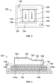
- Figure 3 illustrates a top view of a system 100 for forming a component 102, according to an example of the present disclosure.
- Figure 4 illustrates a side of the system 100 of Figure 3 .
- the component 102 can include different zones, which can be associated with different thicknesses, for example.
- a first zone 140 is associated with a first thickness of the component 102
- a second zone 142 is associated with a second thickness of the component 102.
- the first thickness differs from the second thickness.
- a first heater 104a can be disposed within the first zone 140
- a second heater 104b can be disposed within the second zone 142.
- the first heater 104a and the second heater 104a are within a heater layer 105.
- the control unit 108 operates the first heater 104a and the second heater 104b to heat the different zones 140 and 142 to different temperatures to form the component 102.
- the thicknesses of the zones 140 and 142 can be the same.
- the component 102 may include additional zones configured to be heated to different temperatures.
- the component 102 to be formed can be placed on a substrate 150, such as a tooling or mold.
- the substrate 150 can include vacuum ports 152.
- the component 102 can also include a busbar 154.
- Wires 156 can electrically couple the heaters 104a and 104b to the source of power 106.
- Bagging 160 and insulation 162 can be disposed over the component 102 during the forming process.
- the component 102 to be formed includes various parts.
- the component 102 includes a composite laminate layer 164, a fiberglass layer 166, the busbar(s) 154, the heaters 104a and 104b in the heater layer 105, and a fiberglass layer 168.
- the component 102 can include more or less parts than shown.
- the heaters 104a and 104b that will become a part of the component 102 are used to generate heat to form the component 102, such as to cure the various parts together.
- Figure 5 illustrates a schematic diagram of the system 100 for forming the component 102, according to an example of the present disclosure.
- the control unit 108 is used to control operation of the heaters 104a and 104b to generate heat in relation to the zones 140 and 142 to form the component 102.
- a user interface 170 can be used monitor and control operation.
- the user interface 170 includes a display 172 (such as an electronic screen or monitor) and an input device 174 (such as keyboard, mouse, touchscreen interface, stylus, and/or the like).
- the user interface 170 is in communication with the control unit 108, such as through one or more wired or wireless connections.
- the user interface 170 includes the control unit 108.
- the control unit 108 (and the user interface 170) can also be in communication with an imaging device 176, such as a thermal camera, an infrared camera, and/or the like.
- the imaging device 176 is configured to acquire images of the component 102 during the forming process.
- the imaging device 176 is in communication with the control unit 108, such as through one or more wired or wireless connections.
- the control unit 108 receives signals including the acquired images to monitor the temperatures of the component 102, such as the different zones 140 and 142, and adapt control of the heaters 104a and 104b accordingly.
- the system 100 does not include the imaging device 176.
- the control unit 108 can also be in communication with one or more thermometers that are configured to detect temperatures of the component 102 during the forming process.
- different thermometers can be disposed on or proximate to the different zones 140 and 142.
- the control unit 108 receives signals from the thermometer(s) to monitor the temperatures of the component 102, such as the different zones 140 and 142, and adapt control of the heaters 104a and 104b accordingly.
- the system 100 does not include the thermometers.
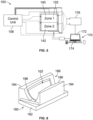
- Figure 6 illustrates an isometric view of the component 102 within a tool 180, according to an example of the present disclosure.
- the tool 180 is an example of the substrate 150 shown in Figures 3 and 4 .
- the tool 180 includes a base 182 and one or more upstanding walls 184 having arcuate internal surfaces 186 that are configured to cradle the component 102 to provide a desired shape during the forming process.
- the tool 180 can be shaped differently than shown in Figure 6 .
- the tool 180 can be a flat mold. In at least one other example, a tool may not be used.
- the arcuate internal surfaces 186 of the tool 180 define a curved receiving chamber 188 for the component 102 to be formed.
- the component 102 can include zones of different thickness, pad up regions, and/or the like.
- the control unit 108 can operate the heater(s) 104 to generate heat of varying temperatures, such as in relation to the different zones 140 and 142.
- the heater(s) 104 provide a conductive heater layer network sandwiched between dielectrics on a composite structure, and electrically connected to a power source (via wires or other arrangements).
- the heaters(s) 104 generate heat from within the component 102 to increase the temperature of the component 102. Temperatures of the component 102 can be tracked (such as via the imaging device 176 in communication with the control unit 108), and subsequently controlled by the control unit 108, such as by varying electrical power input to the heater(s) 104.
- the heater(s) 104 and parts 110 can be placed at any depth within a laminate stacking.
- the parts 110 can include a dielectric layer that electrically isolates the heater(s) 104 from composite laminate to restrict applied electrical power into the heater layer 105.
- the composite materials can be in uncured, semicured, or pre-cured.
- the substrate 150 such as the tool 180, assists in holding a shape of the uncured stack of material, and thereby determines a resultant geometry of the component 102 during and after the forming process.
- one or more caul plates can be stacked on top of the component prior to the forming process to control surface quality, and if thermally conductive, can help to spread heat more uniformly across the component 102, particularly between regions. Insulation can be used to trap heat generated from the heater(s) 104 and reduce heat transfer to mediums and materials external to the component 102 (for example, air, external tooling and fixturing).
- FIG. 7 is a perspective illustration of an aircraft 200.
- the aircraft 200 can include one or more component 102, as described herein.
- the component 102 can be an ice protection system installed on the aircraft 200.
- the aircraft 200 may include a fuselage 202 extending from a nose 203 to an empennage 204.
- the empennage 204 may include one or more tail surfaces for directional control of the aircraft 200.
- the aircraft 200 includes a pair of wings 206 extending from the fuselage 202.
- One or more propulsion systems 208 propel the aircraft 200.
- the propulsion systems 208 are supported by the wings 206 of the aircraft 200, but may be mounted to the fuselage or tail in other types of aircraft.
- Each propulsion system 208 includes a rotor assembly 219 with rotors that spin to direct air.
- the rotor assembly 219 of each propulsion system 208 is surrounded by a nacelle 210.
- the nacelle 210 is an outer casing or housing that holds the rotor assembly 219.
- the nacelle 210 includes an inlet section, referred to as an inlet cowl, at a leading or front end of the nacelle 210.
- the nacelle 210 may also include a fan cowl, a thrust reverser section, and an aft fairing section located behind the inlet cowl along a longitudinal length of the nacelle 210.
- the inlet cowl has an inner barrel that defines an air inlet duct for directing air to the rotor assembly 219.
- the nacelle 210 may have an exhaust nozzle 212 (for example, a primary exhaust nozzle and a fan nozzle) at an aft end of the propulsion system 208.
- each propulsion system 208 may include or represent a gas turbine engine.
- the rotor assembly 219 may be a portion of the engine. The engine burns a fuel, such as gasoline, kerosene, biofuel, or other fuel source, to generate thrust for propelling the aircraft 200.
- Figure 8 illustrates an embodiment of the nacelle 210 of one of the propulsion systems 208 of the aircraft 200 according to an example.
- the nacelle 210 extends a length from a front end 220 to an aft end 222 (opposite the front end 220).
- the nacelle 210 may include an inlet cowl 224, a fan cowl 226 disposed aft of the inlet cowl 224, and at least one aft section 228 disposed aft of the fan cowl 226.
- the inlet cowl 224 defines a leading edge 230 of the nacelle 210 at the front end 220 to direct air into a core 232 of the nacelle 210.
- FIG 9 is a front view of the inlet cowl 224 shown in Figure 8 .
- the inlet cowl 224 has an annular barrel shape that defines a central opening 234 that is fluidly connected to the core 232 (shown in Figure 6 ) of the nacelle 210.
- the term "annular barrel shape" means that the inlet cowl 224 defines a closed, ring-like shape when viewed from the front.
- the annular barrel shape is oriented about a central longitudinal axis 236 that extends through the central opening 234.
- the inlet cowl 224 may have a generally cylindrical shape.
- the leading edge 230 may be circular.
- the inlet cowl 224 directs air through the central opening 234 into the core 232.
- the inlet cowl 224 has the leading edge 230, an outer side 238 and an inner side 240.
- the outer side 238 extends from the leading edge 230 to an outer aft edge 242.
- the inner side 240 extends from the leading edge 230 to an inner aft edge 244.
- the outer side 238 is radially outside of the inner side 240 and surrounds the inner side 240.
- the inner side 240 may define the central opening 234 that operates as an intake duct to supply air into the core 232 for the rotor assembly 219.
- the inlet cowl 224 may define a cavity (not shown) that is aft of the leading edge 230 and radially disposed between the outer side 238 and the inner side 240.
- the component 102 (shown and described with respect to Figures 1-6 ) is used to define the leading edge 230 of the inlet cowl 224.
- the component 102 may be formed into the annular barrel shape.
- An ice protection system including the heater(s) 104 may define the skin of the inlet cowl 224 that is exposed to the ambient environment.
- the component 102 is one panel of multiple different panels assembled side by side along the circumference of the inlet cowl 224.
- a first component 102 (such as a first laminated structure) may be assembled adjacent to a second component 102 (such as a second laminated structure) that has the same or a similar composition, shape, and size as the first component 102.
- the component 102 may be a unitary, one-piece structure that forms the entire annular leading edge 230 without any seams.
- the component 102 optionally may include multiple electrical loads within the thickness, and the electrical loads may be separated from one another at seams.
- the component 102 may be, or otherwise form a portion of, an electric ice protection system (EIPS) that is used to meet engine ice accretion and ingestion requirements.
- the electrical loads may be heater elements (for example, electrically resistive plies).
- the heater elements convert electrical energy to thermal energy to warm the skin of the inlet cowl 224 along the leading edge 230.
- the component(s) 102 include multiple heater elements spaced apart from one another by seams. The heater elements are arranged along the circumference of the inlet cowl 224, such that each heater element defines a respective heater zone 252 that represents a circumferential section of the leading edge 230.
- Figure 10 shows a portion of the inlet cowl 224 indicated by the dashed circle 251 in Figure 9 .
- the seams 250 are not oriented parallel to the central longitudinal axis 236 and/or the streamwise direction of airflow through the central opening 234.
- heater elements may be arranged such that the seams 250 defined between adjacent heater elements define an oblique angle 256 relative to the central longitudinal axis 236 and a streamwise direction of airflow 258 through the inlet cowl 224.
- the oblique angle 256 is not parallel or perpendicular.
- the oblique angle 256 is between 1 and 89 degrees.
- the oblique angle 256 may be between 20 and 70 degrees.
- the oblique angle 256 may be between 30 and 60 degrees.
- the seams 250 are oriented such that the seams 250 define an oblique angle relative to an entire range 260 of streamwise airflow directions that the aircraft 200 may experience in flight.
- the range 260 may be defined between a maximum ascent angle 262 (while the aircraft is ascending) and a maximum descent angle 264 (while the aircraft is descending).
- the range 260 may be the maximum ascent angle 262 plus the maximum descent angle 264.
- the seams 250 are oriented oblique to the current streamwise direction of airflow 258.
- the seams 250 represent areas along the inlet cowl 224 that risk ice accumulation because the seams 250 may have a lower thermal flux than the adjacent heater zones 252.
- the ice accumulation can negatively affect aerodynamic properties of the aircraft 200 and may also potentially damage or increase wear on the rotor assembly 219.
- the inlet cowl 224 avoids ice build-up.
- the cold air moving in the airflow direction 258 only intersects the seams 250 at small areas before traversing the heater zones 252. Most cold air is heated along a first heater area 252, then traverses across a seam 250 before being heated along a second heater area 252.
- examples of the present disclosure provide an improved system and method for forming a component, such as a composite part. Further, examples of the present disclosure provide an efficient and effective system for forming a composite part.
- a structure, limitation, or element that is "configured to” perform a task or operation is particularly structurally formed, constructed, or adapted in a manner corresponding to the task or operation.
- an object that is merely capable of being modified to perform the task or operation is not “configured to” perform the task or operation as used herein.
Landscapes
- Physics & Mathematics (AREA)
- Health & Medical Sciences (AREA)
- Oral & Maxillofacial Surgery (AREA)
- Thermal Sciences (AREA)
- Chemical & Material Sciences (AREA)
- Engineering & Computer Science (AREA)
- Composite Materials (AREA)
- Mechanical Engineering (AREA)
- Moulding By Coating Moulds (AREA)
Abstract
Description
- This application relates to and claims priority benefits from
U.S. Provisional Patent Application No. 63/589,684, filed October 12, 2023 - The present disclosure generally relates to a system and a method for forming, such as via integral curing, a component, such as a composite laminate part.
- Composite materials have been used as structural elements in various applications. Composite materials, such as fiber-reinforced polymers, have a relatively high strength to weight ratio. The high strength to weight ratio makes these materials desirable for vehicle construction, such as aircraft. These materials typically include many layers or plies of a reinforcement material bound within a matrix material to form a heterogenous material with combined properties that are different from the reinforcement material and matrix materials individually.
- For some applications, it is desirable for the composite material to provide multiple functions. For example, it may be desirable to have a single laminate structure that provides both structural support and conducts current for powering an electrical load, communication transmission, and/or the like. Power distribution to embedded conductive materials within a laminated composite structure requires a means of delivering electric current to a known location in the thickness and specific region of the laminated structure.
- Some existing systems embed one or more insulated wires through the thickness of the laminate structure. The assembly of the laminate may include forming cut-outs or splices through multiple plies, and feeding the wire through the cut-outs as the plies are sequentially applied on a mandrel or other tool to form a laminate stack up. This process of embedding wires into the structure at multiple locations during the structure formation can be detrimental to structural properties of the laminate structure and can inhibit proper interfaces between structural plies of the laminate structure and adjacent components, such as a cellular core. For example, routing wires through the surface of the laminate structure at multiple locations may result in discontinuities, such as bumps and stress concentrations, within the laminate structure. The discontinuities may degrade the structural properties of the laminate, requiring additional plies (and therefore weight) to satisfy material strength requirements. Furthermore, the insulation material of the wires may contaminate the matrix material (e.g., resin) of the laminate structure, degrading the material properties. Wire stripping and other wire preparation and routing tasks may increase the risk of foreign object debris (FOD) contaminating the laminate structure. The embedded wires also may introduce a failure risk attributable to handling of the wires and interference between the wires and adjacent components. During the life of the system, the embedded wires may experience fatigue and wear over time which could cause the wires to fail.
- During a forming process such as a composite fabrication process, various types of components are cured. Typically, aerospace composite parts are cured via convective heating processes that are long, slow, and expensive. These processes, often performed in a heating chamber of an autoclave or oven, involve heating up the air and/or gas volume, which then transfers heat to a large tool, and in turn transfers heat to the part. In tooling where closed-mold systems are not employed, the air/gas volume also transfer heat to the part through several layers of bagging materials on a side opposite the tool. Such a process typically inefficiently delivers energy to the part. In particular, the amount of energy imparted onto the part for curing is typically only a fraction of the combined energy of heating the mass of air, tooling, and bagging materials. Additionally, the large thermal mass of the system results in imprecise control of part temperature rise, dwell, and fall, thereby posing challenges in relation to tailoring temperatures to discrete regions of composite parts (for example, thicker regions, and pad-ups that heat slower generally limit process speeds and may have nonuniformity in curing). Also, part sizes are constrained by a size of the heating chamber. As such, production rates are typically limited by a footprint of these chambers, as well as the loading and unloading times.
- A need exists for an improved system and method for forming, such as via curing, a component, such as a laminate composite part. Further, a need exists for an efficient and effective system for forming a composite part.
- With those needs in mind, the present disclosure provides a system for forming a component. The system includes one or more heaters configured to generate heat to form the component. The component, upon formation, includes the one or more heaters.
- In at least one example, the component, upon formation, further includes one or more parts. The one or more heaters are configured to generate the heat to one or more of join, consolidate, fabricate, or cure the one or more parts and the one or more heaters together to form the component. The one or more parts can include one or more composite layers, and one or more dielectric layers,
- In at least one example, the component is an ice protection system configured for a nacelle of a propulsion system, and/or a leading edge of a lifting surface of an aircraft.
- The system can also include a control unit in communication with the one or more heaters. The control unit is configured to control operation of the one or more heaters.
- The one or more heaters can be one or more electrically resistive heaters.
- In at least one example, the one or more heaters are used to form the component, and for functional heating of the component after the component is formed.
- In at least one example, the one or more heaters are configured to heat a first zone of the component to a different temperature than a second zone of the component. For example, the one or more heaters include a first heater configured to heat the first zone, and a second heater configured to heat the second zone.
- The system can also include an imaging device configured to acquire images of the component as the component is formed.
- Furthermore, the present disclosure provides a method for forming a component. The method includes generating, by one or more heaters, heat to form the component; and forming the component, at least in part, by said generating, wherein the component, upon formation, includes the one or more heaters.
- These and other features, aspects, and advantages of the present disclosure will become better understood when the following detailed description is read with reference to the accompanying drawings in which like numerals represent like parts throughout the drawings, wherein:
-
Figure 1 illustrates a block diagram of a system for forming a component, according to an example of the present disclosure. -
Figure 2 illustrates a flow chart of a method for forming a component, according to an example of the present disclosure. -
Figure 3 illustrates a top view of a system for forming a component, according to an example of the present disclosure. -
Figure 4 illustrates a side of the system ofFigure 3 . -
Figure 5 illustrates a schematic diagram of a system for forming a component, according to an example of the present disclosure. -
Figure 6 illustrates an isometric view of a component within a tool, according to an example of the present disclosure. -
Figure 7 illustrates a perspective view of an aircraft. -
Figure 8 illustrates an isometric lateral view a nacelle of a propulsion system of the aircraft. -
Figure 9 illustrates a front view of an inlet cowl of the nacelle shown inFigure 8 . -
Figure 10 shows a portion of the inlet cowl indicated by a dashed circle inFigure 9 . - The foregoing summary, as well as the following detailed description of certain embodiments will be better understood when read in conjunction with the appended drawings. As used herein, an element or step recited in the singular and preceded by the word "a" or "an" should be understood as not necessarily excluding the plural of the elements or steps. Further, references to "one embodiment" are not intended to be interpreted as excluding the existence of additional embodiments that also incorporate the recited features. Moreover, unless explicitly stated to the contrary, embodiments "comprising" or "having" an element or a plurality of elements having a particular property may include additional elements not having that property.
- Examples of the present disclosure provide a system and method for efficiently and effectively forming (such as fabricating, curing, hearing, and/or the like) a component, such as a laminate composite part. The component is formed through heating in order to join, fabricate, consolidate, cure, and/or the like various portions together. In at least one example, embedded heaters within the component are used to cure the component, thereby resulting in direct conductive heat transfer from the heaters to a matrix (for example, a polymer resin). Using the embedded heaters, which are an integral portion of the component, reduces the amount of heat transfer to the surrounding tooling, air/gas volume, and part itself, thereby greatly increasing efficiency and rate while reducing wasted energy. Consequently, the lower thermal mass of the system and conductive heat transfer allows for fast and tighter control of the temperature of the component, which is desirable for optimizing cure cycles, reducing change of overshoots, and uncontrolled exothermic events. In short, examples of the present disclosure enable faster curing, and higher composite part quality. Examples of the present disclosure can also be used with materials other than composites.
- Further, examples of the present disclosure are used to form a multifunctional structure, in which the embedded heaters can also serve as a lightweight heater for the component, such as an ice protection system for a portion of an aircraft. For example, the heater(s) of the ice protection system are used to cure the ice protection system during a forming process. Such methods eliminate, minimize, or otherwise reduce a need for any other large heating chambers (for example, ovens or autoclaves), which reduces manufacturing, labor, and processing times and costs.
-
Figure 1 illustrates a block diagram of asystem 100 for forming acomponent 102, according to an example of the present disclosure. Thesystem 100 includes one ormore heaters 104 of thecomponent 102. The heater(s) 104 are in communication with a source ofpower 106, such as through one or more wired connections (for example, one or more leads, bus bars, and/or the or the like). The heater(s) 104 are also in communication with acontrol unit 108, such as through one or more wired or wireless connections. In at least one example, thepower 106 is wired to thecontrol unit 108, which can provide power to the heater(s) 104. - In at least one example, the
component 102 includes one ormore parts 110, such as composite layers, such as one or more carbon layers (for example, a carbon veil having one or carbon fibers, carbon nanotubes, and/or the like), one or more dielectric layers (such as including fiberglass prepreg and adhesives) one or more film layers, one or more adhesive layers, and/or the like. Thecomponent 102 also includes the heater(s) 104. Thecomponent 102 can also include wires for connections to the heater(s) 104. That is, thecomponent 102, upon formation (such as via, for example, heating, curing, and/or fabricating), includes the heater(s) 104, which are used during a lifetime of thecomponent 102. For example, thecomponent 102 upon formation can be a laminated composite structure that includes the heater(s) 104, which are used during the lifetime of the formedcomponent 102. The heater(s) 104 are not removed from thecomponent 102. Instead, the heater(s) 104 are an integral and functional portion of thecomponent 102. The heater(s) 104 can be electrically resistive heaters. The heaters(s) 104 can be electrically-powered resistive layers that are integrated into the component 102 (such as composite laminate) and configured for other desired functionality after thecomponent 102 is formed. For example, the heater(s) 104 can be used with respect to an ice protection system for a nacelle of a propulsion system of an aircraft. In this manner, the heater(s) 104 are used for different purposes, such as to form thecomponent 102, and for functional heating after thecomponent 102 is formed and complete. - In at least one example, the
component 102 includes asingle heater 104. As another example, thecomponent 102 includes twomore heaters 104. In at least one example, the heater(s) 104 form one ormore heater layers 105 of thecomponent 102. Theheater layer 105 is an electrical layer configured to generate heat. In at least one example, theheater layer 105 is a carbon veil, which includes randomly oriented carbon fibers. As another example, theheater layer 105 includes carbon nanotubes. Theheater layer 105 can be any type of continuously conductive material configured to provide an electrically resistive heater. For example, electrical current generated by the source ofpower 106 flows into theheater layer 105, thereby increasing the temperature of theheater layer 105. - In operation, in order to form (such as via curing) the
component 102, thecontrol unit 108 operates the heater(s) 104 (of thecomponent 102 to be formed) to heat the one ormore parts 110 and the heater(s) 104 to join, consolidate, fabricate, cure, and/or the like the one ormore parts 110 and the one ormore heaters 104 together. Thecontrol unit 108 operates to control the heater(s) 104 to heat one or more portions of thecomponent 102 to desired temperatures. As such, thecomponent 102 is formed via internal heating, generated by the one ormore heaters 104, instead of being disposed within a heating chamber of an oven, autoclave or the like. Thecomponent 102 is formed via heat generated from the heater(s) 104 from an inside of the component 102 (in contrast to external heat within an internal chamber of an oven, autoclave, or the like). Thecomponent 102 is formed through heat generated by the heater(s) 104, which, themselves become an integral part of thecomponent 102. After the heater(s) 104 are operated to form thecomponent 102, the heater(s) 104 are an integral part of thecomponent 102, as formed. The heater(s) 104 are used during a lifetime of thecomponent 102. For example, the heater(s) 104 can be part of an ice protection system of a nacelle of a propulsion system of an aircraft. Additionally, the heater(s) 104 can be used during a maintenance operation of thecomponent 102 to reform thecomponent 102. For example, if apart 110, such as a composite layer, is replaced, the heater(s) 104 can be operated to generate heat to reform thecomponent 102 with areplacement part 110, instead of using an oven or autoclave to reform thecomponent 102. - The
system 100 including the heater(s) 104 of thecomponent 102 efficiently forms (such as by heating to join, consolidate, fabricate, cure, and/or the like various portions together) thecomponent 102 by using integral, embedded heater(s) 104. For example, the heater(s) 104 cure composite laminate parts and the heater(s) 104 together, thereby resulting in direct conductive heat transfer from the heater(s) 104 to a matrix (for example, polymer resin) of thecomponent 102. By using the heater(s) 104 to internally heat thecomponent 102 during a forming process, an amount of heat transfer to surrounding tooling, air and thecomponent 102 itself is reduced (as compared to using an oven or autoclave). As such, a lower thermal mass of thesystem 100 and conductive heat transfer allows for faster and tighter control of the temperature of thecomponent 102, which is desirable for optimizing cure cycles, reducing chance of overshoots, exotherms, and the like. - As described herein, the
system 100 for forming thecomponent 102 includes the heater(s) 104, which are configured to generate heat to form thecomponent 102. Upon formation, thecomponent 102 includes the heater(s) 104. Thecomponent 102 also includes the part(s,) 110. The heater(s) 104 are configured to generate the heat to join, consolidate, fabricate, or cure the part(s) 110 and the heater(s) 104 together to form thecomponent 102. -
Figure 2 illustrates a flow chart of a method for forming a component, according to an example of the present disclosure. Referring toFigures 1 and 2 , at 120, one ormore heaters 104 are disposed on or within one or more other parts of thecomponent 102 to be formed. The other parts can include one or more adhesives, films, structural layers, bus bars, and/or the like. At 122, thecontrol unit 108 operates the heater(s) 104 to generate heat at one or more desired temperatures or power input levels for one or more desired time periods. At 124, thecomponent 102 including the heater(s) 104 and the other parts is formed via the heat generated by the heater(s) 104. The integral, embedded heater(s) 104 of thecomponent 102 itself are used to form (such as by generated heat to join, consolidate, fabricate, cure, and/or the like) thecomponent 102. After thecomponent 102 is formed, the heater(s) 104 can be used to generate heat as a function of the component 102 (such as to prevent ice formation on a structure, heat a structure, and/or the like). - The systems and methods described herein use the heater(s) 104 (such as embedded electrical heaters) in a component 102 (such as composite laminate) during a forming process of the
component 102. For example, the heater(s) 104 are used to cure or assist curing of thecomponent 102. It has been found that the energy used to conductively cure a composite part using the integral, embedded heater(s) is an order of magnitude lower compared to an appropriately sized convective heating chamber such as an autoclave or oven. This is due to lower overall heated thermal mass and the heat flow direction from inside-out (from the embedded heater(s) 104 within the component 102), in contrast to outside-in (from the tooling or heated air/gas) in a convectively cured scenario. - It has been found the heater(s) 104 can rapidly heat up and closely track a prescribed temperature cure profile for composite laminates, even across laminates with zones of different laminate thicknesses, thereby resulting in cure time savings as part temperatures meet dwell temperature specifications sooner. Further,
multiple heaters 104 can be used to generate heat in different zones of thecomponent 102. The zones can correspond to regions having different thicknesses. As such, thecontrol unit 108 can operate to tailor and control the heating for each zone independently such that temperature setpoints can be met quickly and efficiently even in complex parts. - Additionally the integral heater(s) 104 enable curing without the use of an oven or autoclave, and without expensive and pressure-rated tooling, thereby reducing equipment costs and loading times. Further, the integral heater(s) 104 allow for formation of large-scale, single piece composite parts that are not limited to chamber sizes (such as of ovens or autoclaves), which reduces structural design weight of a part as fasteners and structural interfaces can be reduced.
- Additionally, thermally insulating tooling can be used to further increase efficiency by trapping heat provided by the heater(s) 104 from within the
component 102. Also, the embedded heater(s) 104 can also assist with convective curing processes. For example, acomponent 102 with the embedded heater(s) 104 can be heated nominally in a heating chamber (such as of an oven or autoclave), while also having electrical power delivered to the embeddedheaters 104, thereby resulting in heating from both within and outside of thecomponent 102. The net effect is faster ramp-to-dwell temperatures, and improved temperature uniformity of thecomponent 102. Also, the embeddedheaters 104 can also assist with structural repair of thecomponent 102, such as by providing internal heating that can be used to cure adhesives and patches of reinforcing materials around damaged areas. - As used herein, the term "control unit," "central processing unit," "CPU," "computer," or the like may include any processor-based or microprocessor-based system including systems using microcontrollers, reduced instruction set computers (RISC), application specific integrated circuits (ASICs), logic circuits, and any other circuit or processor including hardware, software, or a combination thereof capable of executing the functions described herein. Such are exemplary only, and are thus not intended to limit in any way the definition and/or meaning of such terms. For example, the
control unit 108 may be or include one or more processors that are configured to control operation, as described herein. - The
control unit 108 is configured to execute a set of instructions that are stored in one or more data storage units or elements (such as one or more memories), in order to process data. For example, thecontrol unit 108 may include or be coupled to one or more memories. The data storage units may also store data or other information as desired or needed. The data storage units may be in the form of an information source or a physical memory element within a processing machine. - The set of instructions may include various commands that instruct the
control unit 108 as a processing machine to perform specific operations such as the methods and processes of the various examples of the subject matter described herein. The set of instructions may be in the form of a software program. The software may be in various forms such as system software or application software. Further, the software may be in the form of a collection of separate programs, a program subset within a larger program, or a portion of a program. The software may also include modular programming in the form of object-oriented programming. The processing of input data by the processing machine may be in response to user commands, or in response to results of previous processing, or in response to a request made by another processing machine. - The diagrams of examples herein may illustrate one or more control or processing units, such as the
control unit 108. It is to be understood that the processing or control units may represent circuits, circuitry, or portions thereof that may be implemented as hardware with associated instructions (for example, software stored on a tangible and non-transitory computer readable storage medium, such as a computer hard drive, ROM, RAM, or the like) that perform the operations described herein. The hardware may include state machine circuitry hardwired to perform the functions described herein. Optionally, the hardware may include electronic circuits that include and/or are connected to one or more logic-based devices, such as microprocessors, processors, controllers, or the like. Optionally, thecontrol unit 108 may represent processing circuitry such as one or more of a field programmable gate array (FPGA), application specific integrated circuit (ASIC), microprocessor(s), and/or the like. The circuits in various examples may be configured to execute one or more algorithms to perform functions described herein. The one or more algorithms may include aspects of examples disclosed herein, whether or not expressly identified in a flowchart or a method. - As used herein, the terms "software" and "firmware" are interchangeable, and include any computer program stored in a data storage unit (for example, one or more memories) for execution by a computer, including RAM memory, ROM memory, EPROM memory, EEPROM memory, and non-volatile RAM (NVRAM) memory. The above data storage unit types are exemplary only, and are thus not limiting as to the types of memory usable for storage of a computer program.
-
Figure 3 illustrates a top view of asystem 100 for forming acomponent 102, according to an example of the present disclosure.Figure 4 illustrates a side of thesystem 100 ofFigure 3 . Thecomponent 102 can include different zones, which can be associated with different thicknesses, for example. For example, afirst zone 140 is associated with a first thickness of thecomponent 102, while asecond zone 142 is associated with a second thickness of thecomponent 102. The first thickness differs from the second thickness. Afirst heater 104a can be disposed within thefirst zone 140, while asecond heater 104b can be disposed within thesecond zone 142. Thefirst heater 104a and thesecond heater 104a are within aheater layer 105. Referring toFigures 1 ,3, and 4 , thecontrol unit 108 operates thefirst heater 104a and thesecond heater 104b to heat thedifferent zones component 102. Optionally, the thicknesses of thezones component 102 may include additional zones configured to be heated to different temperatures. - The
component 102 to be formed can be placed on asubstrate 150, such as a tooling or mold. Thesubstrate 150 can includevacuum ports 152. Thecomponent 102 can also include abusbar 154.Wires 156 can electrically couple theheaters power 106. Bagging 160 andinsulation 162 can be disposed over thecomponent 102 during the forming process. - The
component 102 to be formed includes various parts. For example, thecomponent 102 includes acomposite laminate layer 164, afiberglass layer 166, the busbar(s) 154, theheaters heater layer 105, and afiberglass layer 168. Thecomponent 102 can include more or less parts than shown. As described, theheaters component 102 are used to generate heat to form thecomponent 102, such as to cure the various parts together. -
Figure 5 illustrates a schematic diagram of thesystem 100 for forming thecomponent 102, according to an example of the present disclosure. Referring toFigures 1-5 , as noted, thecontrol unit 108 is used to control operation of theheaters zones component 102. Auser interface 170 can be used monitor and control operation. For example, theuser interface 170 includes a display 172 (such as an electronic screen or monitor) and an input device 174 (such as keyboard, mouse, touchscreen interface, stylus, and/or the like). Theuser interface 170 is in communication with thecontrol unit 108, such as through one or more wired or wireless connections. In at least one example, theuser interface 170 includes thecontrol unit 108. - The control unit 108 (and the user interface 170) can also be in communication with an
imaging device 176, such as a thermal camera, an infrared camera, and/or the like. Theimaging device 176 is configured to acquire images of thecomponent 102 during the forming process. Theimaging device 176 is in communication with thecontrol unit 108, such as through one or more wired or wireless connections. Thecontrol unit 108 receives signals including the acquired images to monitor the temperatures of thecomponent 102, such as thedifferent zones heaters system 100 does not include theimaging device 176. - The
control unit 108 can also be in communication with one or more thermometers that are configured to detect temperatures of thecomponent 102 during the forming process. For example, different thermometers can be disposed on or proximate to thedifferent zones control unit 108 receives signals from the thermometer(s) to monitor the temperatures of thecomponent 102, such as thedifferent zones heaters system 100 does not include the thermometers. -
Figure 6 illustrates an isometric view of thecomponent 102 within atool 180, according to an example of the present disclosure. Thetool 180 is an example of thesubstrate 150 shown inFigures 3 and 4 . Thetool 180 includes abase 182 and one or moreupstanding walls 184 having arcuateinternal surfaces 186 that are configured to cradle thecomponent 102 to provide a desired shape during the forming process. Thetool 180 can be shaped differently than shown inFigure 6 . In at least one example, thetool 180 can be a flat mold. In at least one other example, a tool may not be used. - The arcuate
internal surfaces 186 of thetool 180 define acurved receiving chamber 188 for thecomponent 102 to be formed. Thecomponent 102 can include zones of different thickness, pad up regions, and/or the like. Referring toFigures 1-6 , thecontrol unit 108 can operate the heater(s) 104 to generate heat of varying temperatures, such as in relation to thedifferent zones - Referring to
Figures 1-6 , in a least one example, the heater(s) 104 provide a conductive heater layer network sandwiched between dielectrics on a composite structure, and electrically connected to a power source (via wires or other arrangements). The heaters(s) 104 generate heat from within thecomponent 102 to increase the temperature of thecomponent 102. Temperatures of thecomponent 102 can be tracked (such as via theimaging device 176 in communication with the control unit 108), and subsequently controlled by thecontrol unit 108, such as by varying electrical power input to the heater(s) 104. The heater(s) 104 andparts 110 can be placed at any depth within a laminate stacking. - The
parts 110 can include a dielectric layer that electrically isolates the heater(s) 104 from composite laminate to restrict applied electrical power into theheater layer 105. Before the forming process, the composite materials can be in uncured, semicured, or pre-cured. Thesubstrate 150, such as thetool 180, assists in holding a shape of the uncured stack of material, and thereby determines a resultant geometry of thecomponent 102 during and after the forming process. Additionally, one or more caul plates can be stacked on top of the component prior to the forming process to control surface quality, and if thermally conductive, can help to spread heat more uniformly across thecomponent 102, particularly between regions. Insulation can be used to trap heat generated from the heater(s) 104 and reduce heat transfer to mediums and materials external to the component 102 (for example, air, external tooling and fixturing). -
Figure 7 is a perspective illustration of anaircraft 200. Theaircraft 200 can include one ormore component 102, as described herein. For example, thecomponent 102 can be an ice protection system installed on theaircraft 200. Theaircraft 200 may include afuselage 202 extending from anose 203 to anempennage 204. Theempennage 204 may include one or more tail surfaces for directional control of theaircraft 200. Theaircraft 200 includes a pair ofwings 206 extending from thefuselage 202. One ormore propulsion systems 208 propel theaircraft 200. Thepropulsion systems 208 are supported by thewings 206 of theaircraft 200, but may be mounted to the fuselage or tail in other types of aircraft. Eachpropulsion system 208 includes arotor assembly 219 with rotors that spin to direct air. - The
rotor assembly 219 of eachpropulsion system 208 is surrounded by anacelle 210. Thenacelle 210 is an outer casing or housing that holds therotor assembly 219. Thenacelle 210 includes an inlet section, referred to as an inlet cowl, at a leading or front end of thenacelle 210. Thenacelle 210 may also include a fan cowl, a thrust reverser section, and an aft fairing section located behind the inlet cowl along a longitudinal length of thenacelle 210. The inlet cowl has an inner barrel that defines an air inlet duct for directing air to therotor assembly 219. Thenacelle 210 may have an exhaust nozzle 212 (for example, a primary exhaust nozzle and a fan nozzle) at an aft end of thepropulsion system 208. In an example, eachpropulsion system 208 may include or represent a gas turbine engine. Therotor assembly 219 may be a portion of the engine. The engine burns a fuel, such as gasoline, kerosene, biofuel, or other fuel source, to generate thrust for propelling theaircraft 200. -
Figure 8 illustrates an embodiment of thenacelle 210 of one of thepropulsion systems 208 of theaircraft 200 according to an example. Thenacelle 210 extends a length from afront end 220 to an aft end 222 (opposite the front end 220). Thenacelle 210 may include aninlet cowl 224, afan cowl 226 disposed aft of theinlet cowl 224, and at least oneaft section 228 disposed aft of thefan cowl 226. Theinlet cowl 224 defines aleading edge 230 of thenacelle 210 at thefront end 220 to direct air into acore 232 of thenacelle 210. -
Figure 9 is a front view of theinlet cowl 224 shown inFigure 8 . Theinlet cowl 224 has an annular barrel shape that defines acentral opening 234 that is fluidly connected to the core 232 (shown inFigure 6 ) of thenacelle 210. The term "annular barrel shape" means that theinlet cowl 224 defines a closed, ring-like shape when viewed from the front. The annular barrel shape is oriented about a centrallongitudinal axis 236 that extends through thecentral opening 234. Theinlet cowl 224 may have a generally cylindrical shape. For example, theleading edge 230 may be circular. Theinlet cowl 224 directs air through thecentral opening 234 into thecore 232. - The
inlet cowl 224 has theleading edge 230, anouter side 238 and aninner side 240. Theouter side 238 extends from theleading edge 230 to an outeraft edge 242. Theinner side 240 extends from theleading edge 230 to an inneraft edge 244. Theouter side 238 is radially outside of theinner side 240 and surrounds theinner side 240. Theinner side 240 may define thecentral opening 234 that operates as an intake duct to supply air into thecore 232 for therotor assembly 219. Theinlet cowl 224 may define a cavity (not shown) that is aft of theleading edge 230 and radially disposed between theouter side 238 and theinner side 240. - In an example, after formation, the component 102 (shown and described with respect to
Figures 1-6 ) is used to define theleading edge 230 of theinlet cowl 224. For example, thecomponent 102 may be formed into the annular barrel shape. An ice protection system including the heater(s) 104 may define the skin of theinlet cowl 224 that is exposed to the ambient environment. Optionally, thecomponent 102 is one panel of multiple different panels assembled side by side along the circumference of theinlet cowl 224. For example, a first component 102 (such as a first laminated structure) may be assembled adjacent to a second component 102 (such as a second laminated structure) that has the same or a similar composition, shape, and size as thefirst component 102. In another example, thecomponent 102 may be a unitary, one-piece structure that forms the entire annularleading edge 230 without any seams. In this one-piece embodiment, thecomponent 102 optionally may include multiple electrical loads within the thickness, and the electrical loads may be separated from one another at seams. - The
component 102 may be, or otherwise form a portion of, an electric ice protection system (EIPS) that is used to meet engine ice accretion and ingestion requirements. The electrical loads may be heater elements (for example, electrically resistive plies). The heater elements convert electrical energy to thermal energy to warm the skin of theinlet cowl 224 along theleading edge 230. In an example, the component(s) 102 include multiple heater elements spaced apart from one another by seams. The heater elements are arranged along the circumference of theinlet cowl 224, such that each heater element defines arespective heater zone 252 that represents a circumferential section of theleading edge 230. - With continued reference to
Figure 9, Figure 10 shows a portion of theinlet cowl 224 indicated by the dashedcircle 251 inFigure 9 . In an example, theseams 250 are not oriented parallel to the centrallongitudinal axis 236 and/or the streamwise direction of airflow through thecentral opening 234. For example, heater elements may be arranged such that theseams 250 defined between adjacent heater elements define anoblique angle 256 relative to the centrallongitudinal axis 236 and a streamwise direction ofairflow 258 through theinlet cowl 224. Theoblique angle 256 is not parallel or perpendicular. For example, theoblique angle 256 is between 1 and 89 degrees. In an example, theoblique angle 256 may be between 20 and 70 degrees. Optionally, theoblique angle 256 may be between 30 and 60 degrees. In an example, theseams 250 are oriented such that theseams 250 define an oblique angle relative to anentire range 260 of streamwise airflow directions that theaircraft 200 may experience in flight. For example, therange 260 may be defined between a maximum ascent angle 262 (while the aircraft is ascending) and a maximum descent angle 264 (while the aircraft is descending). Therange 260 may be themaximum ascent angle 262 plus themaximum descent angle 264. As such, regardless of the angle of attack of the aircraft at a given time during typical flight conditions, theseams 250 are oriented oblique to the current streamwise direction ofairflow 258. - In general, the
seams 250 represent areas along theinlet cowl 224 that risk ice accumulation because theseams 250 may have a lower thermal flux than theadjacent heater zones 252. The ice accumulation can negatively affect aerodynamic properties of theaircraft 200 and may also potentially damage or increase wear on therotor assembly 219. By orienting the heater elements such that theseams 250 between theheater zones 252 are oblique to the streamwise direction ofairflow 258, theinlet cowl 224 avoids ice build-up. For example, the cold air moving in theairflow direction 258 only intersects theseams 250 at small areas before traversing theheater zones 252. Most cold air is heated along afirst heater area 252, then traverses across aseam 250 before being heated along asecond heater area 252. - Further, the disclosure comprises examples according to the following clauses:
-
Clause 1. A system for forming a component, the system comprising:
one or more heaters configured to generate heat to form the component, wherein the component, upon formation, includes the one or more heaters. -
Clause 2. The system ofClause 1, wherein the component, upon formation, further includes one or more parts, and wherein the one or more heaters are configured to generate the heat to one or more of join, consolidate, fabricate, or cure the one or more parts and the one or more heaters together to form the component. - Clause 3. The system of
Clause 2, wherein the one or more parts comprise:- one or more composite layers; and
- one or more dielectric layers,
- Clause 4. The system of any of Clauses 1-3, wherein the component is an ice protection system configured for a nacelle of a propulsion system of an aircraft.
- Clause 5. The system of any of Clauses 1-4, further comprising a control unit in communication with the one or more heaters, wherein the control unit is configured to control operation of the one or more heaters.
- Clause 6. The system of any of Clauses 1-5, wherein the one or more heaters are one or more electrically resistive heaters.
- Clause 7. The system of any of Clauses 1-6, wherein the one or more heaters are used to form the component, and for functional heating of the component after the component is formed.
- Clause 8. The system of any of Clauses 1-7, wherein the one or more heaters are configured to heat a first zone of the component to a different temperature than a second zone of the component.
- Clause 9. The system of Clause 8, wherein the one or more heaters comprise:
- a first heater configured to heat the first zone; and
- a second heater configured to heat the second zone.
- Clause 10. The system of any of Clauses 1-9, further comprising an imaging device configured to acquire images of the component as the component is formed.
- Clause 11. A method for forming a component, the method comprising:
- generating, by one or more heaters, heat to form the component; and
- forming the component, at least in part, by said generating, wherein the component, upon formation, includes the one or more heaters.
- Clause 12. The method of Clause 11, wherein said generating comprises generating, by the one or more heaters, the heat to one or more of join, consolidate, fabricate, or cure one or more parts and the one or more heaters together, and wherein the component, upon formation includes the one or more heaters and the one or more parts.
- Clause 13. The method of Clause 12, wherein the one or more parts comprise:
- one or more composite layers; and
- one or more dielectric layers,
- Clause 14. The method of any of any of Clauses 11-13, wherein the component is an ice protection system configured for a nacelle of a propulsion system of an aircraft.
- Clause 15. The method of any of Clauses 11-14, further comprising controlling, by a control unit in communication with the one or more heaters, operation of the one or more heaters.
- Clause 16. The method of any of Clauses 11-15, wherein the one or more heaters are one or more electrically resistive heaters.
- Clause 17. The method of any of Clauses 11-16, wherein the one or more heaters are used to form the component, and for functional heating of the component after the component is formed.
- Clause 18. The method of any of Clauses 11-17, wherein said generating comprises heating a first zone of the component to a different temperature than a second zone of the component.
- Clause 19. The method of Clause 18, wherein the one or more heaters comprise:
- a first heater configured to heat the first zone; and
- a second heater configured to heat the second zone.
- Clause 20. The method of any of Clauses 11-19, further comprising acquiring, by an imaging device, images of the component during said generating.
- As described herein, examples of the present disclosure provide an improved system and method for forming a component, such as a composite part. Further, examples of the present disclosure provide an efficient and effective system for forming a composite part.
- While various spatial and directional terms, such as top, bottom, lower, mid, lateral, horizontal, vertical, front and the like may be used to describe embodiments of the present disclosure, it is understood that such terms are merely used with respect to the orientations shown in the drawings. The orientations may be inverted, rotated, or otherwise changed, such that an upper portion is a lower portion, and vice versa, horizontal becomes vertical, and the like.
- As used herein, a structure, limitation, or element that is "configured to" perform a task or operation is particularly structurally formed, constructed, or adapted in a manner corresponding to the task or operation. For purposes of clarity and the avoidance of doubt, an object that is merely capable of being modified to perform the task or operation is not "configured to" perform the task or operation as used herein.
- It is to be understood that the above description is intended to be illustrative, and not restrictive. For example, the above-described embodiments (and/or aspects thereof) may be used in combination with each other. While the dimensions and types of materials described herein are intended to define the parameters of the various embodiments of the disclosure, the embodiments are by no means limiting and are example embodiments. Many other embodiments will be apparent to those of ordinary skill in the art upon reviewing the above description. In the appended claims, the terms "including" and "in which" are used as the plain-English equivalents of the respective terms "comprising" and "wherein." Moreover, the terms "first," "second," and "third," etc. are used merely as labels, and are not intended to impose numerical requirements on their objects.
- This written description uses examples to disclose the various embodiments of the disclosure, including the best mode, and also to enable any person skilled in the art to practice the various embodiments of the disclosure, including making and using any devices or systems and performing any incorporated methods. The patentable scope of the various embodiments of the disclosure is defined by the claims, and may include other examples that occur to those skilled in the art. Such other examples are intended to be within the scope of the claims if the examples have structural elements that do not differ from the literal language of the claims, or if the examples include equivalent structural elements with insubstantial differences from the literal language of the claims.
Claims (15)
- A system (100) for forming a component (102), the system (100) comprising:
one or more heaters (104) configured to generate heat to form the component (102), wherein the component (102), upon formation, includes the one or more heaters (104). - The system (100) of claim 1, wherein the component (102), upon formation, further includes one or more parts (110), and wherein the one or more heaters (104) are configured to generate the heat to one or more of join, consolidate, fabricate, or cure the one or more parts (110) and the one or more heaters (104) together to form the component (102).
- The system (100) of claim 2, wherein the one or more parts (110) comprise:one or more composite layers; andone or more dielectric layers,
- The system (100) of any one of the preceding claims, wherein the component (102) is an ice protection system (100) configured for a nacelle of a propulsion system (100) of an aircraft.
- The system (100) of any one of the preceding claims, further comprising a control unit (108) in communication with the one or more heaters (104), wherein the control unit (108) is configured to control operation of the one or more heaters (104).
- The system (100) of any one of the preceding claims, wherein the one or more heaters (104) are one or more electrically resistive heaters (104).
- The system (100) of any one of the preceding claims, wherein the one or more heaters (104) comprise:a first heater configured to heat a first zone (140) of the component (102); anda second heater configured to heat a second zone (142) of the component (102).
- The system (100) of any one of the preceding claims, further comprising an imaging device (176) configured to acquire images of the component (102) as the component (102) is formed.
- A method for forming a component (102), the method comprising:generating, by one or more heaters (104), heat to form the component (102); andforming the component (102), at least in part, by said generating, wherein the component (102), upon formation, includes the one or more heaters (104).
- The method of claim 9, wherein said generating comprises generating, by the one or more heaters (104), the heat to one or more of join, consolidate, fabricate, or cure one or more parts (110) and the one or more heaters (104) together, and wherein the component (102), upon formation includes the one or more heaters (104) and the one or more parts (110).
- The method of any one of claims 9-10, wherein the component (102) is an ice protection system (100) configured for a nacelle of a propulsion system (100) of an aircraft.
- The method of any one of claims 9-11, wherein the one or more heaters (104) are used to form the component (102), and for functional heating of the component (102) after the component (102) is formed.
- The method of any one of claims 9-12, wherein said generating comprises heating a first zone (140) of the component (102) to a different temperature than a second zone (142) of the component (102).
- The method of claim 13, wherein the one or more heaters (104) comprise:a first heater heating the first zone (140); anda second heater heating the second zone (142).
- The method of any one of claims 9-14, further comprising controlling, by a control unit (108) in communication with the one or more heaters (104) operation of the one or more heaters, as well as acquiring, by an imaging device (176), images of the component (102) during said generating.
Applications Claiming Priority (2)
| Application Number | Priority Date | Filing Date | Title |
|---|---|---|---|
| US202363589684P | 2023-10-12 | 2023-10-12 | |
| US18/413,303 US20250121534A1 (en) | 2023-10-12 | 2024-01-16 | System and method for forming a component |
Publications (1)
| Publication Number | Publication Date |
|---|---|
| EP4538027A1 true EP4538027A1 (en) | 2025-04-16 |
Family
ID=92925707
Family Applications (1)
| Application Number | Title | Priority Date | Filing Date |
|---|---|---|---|
| EP24203190.4A Pending EP4538027A1 (en) | 2023-10-12 | 2024-09-27 | System and method for forming a component |
Country Status (3)
| Country | Link |
|---|---|
| US (1) | US20250121534A1 (en) |
| EP (1) | EP4538027A1 (en) |
| CN (1) | CN119820880A (en) |
Citations (3)
| Publication number | Priority date | Publication date | Assignee | Title |
|---|---|---|---|---|
| CN107662303B (en) * | 2017-10-16 | 2019-06-11 | 南京航空航天大学 | A comprehensive electrical loss curing method for carbon fiber reinforced resin matrix composites |
| US20220032563A1 (en) * | 2020-07-28 | 2022-02-03 | Colorado State University Research Foundation | Device and method for rapid manufacturing of multifunctional composites |
| EP4289589A1 (en) * | 2022-06-10 | 2023-12-13 | Rohr, Inc. | Curing thermoset material using electric heater(s) for thermal anti-icing system |
-
2024
- 2024-01-16 US US18/413,303 patent/US20250121534A1/en active Pending
- 2024-09-13 CN CN202411286943.5A patent/CN119820880A/en active Pending
- 2024-09-27 EP EP24203190.4A patent/EP4538027A1/en active Pending
Patent Citations (3)
| Publication number | Priority date | Publication date | Assignee | Title |
|---|---|---|---|---|
| CN107662303B (en) * | 2017-10-16 | 2019-06-11 | 南京航空航天大学 | A comprehensive electrical loss curing method for carbon fiber reinforced resin matrix composites |
| US20220032563A1 (en) * | 2020-07-28 | 2022-02-03 | Colorado State University Research Foundation | Device and method for rapid manufacturing of multifunctional composites |
| EP4289589A1 (en) * | 2022-06-10 | 2023-12-13 | Rohr, Inc. | Curing thermoset material using electric heater(s) for thermal anti-icing system |
Also Published As
| Publication number | Publication date |
|---|---|
| US20250121534A1 (en) | 2025-04-17 |
| CN119820880A (en) | 2025-04-15 |
Similar Documents
| Publication | Publication Date | Title |
|---|---|---|
| CA2941034C (en) | Advanced multiple grid heat sources to achieve optimized cure structure and method of making the same | |
| EP3078471B1 (en) | Co-curing process for the joining of composite structures | |
| US11746673B2 (en) | Manufacture of a fan track liner | |
| US10343761B2 (en) | Repair method of repair target portion, repaired product, and repair apparatus | |
| CA2794770C (en) | Unitized engine nacelle structure | |
| CN102137748B (en) | Method for manufacturing parts made of fiber-reinforced composite materials by microwave polymerization | |
| US20120039720A1 (en) | Method of manufacturing a wind turbine blade by embedding a layer of pre-cured fibre reinforced resin | |
| EP2944452A2 (en) | Thermoformed cascades for jet engine thrust reversers | |
| EP3313638B1 (en) | Method of making a wind turbine blade | |
| US10035303B2 (en) | Method and device for joining components | |
| EP2591911A1 (en) | A method for the automated manufacture of a fibre composite component with integrated lightning protection, and also a fibre composite component | |
| US11338933B2 (en) | Acoustic honeycomb panel with integrated electrical heater | |
| CN107567381B (en) | Method for producing a composite component | |
| EP4538027A1 (en) | System and method for forming a component | |
| EP3002100B1 (en) | Systems and methods for curing complex fiber-reinforced composite structures | |
| US11117359B2 (en) | Gradient curing of composite laminate parts | |
| EP2913178A1 (en) | Cylindrical case and method for manufacturing cylindrical case | |
| EP4289589B1 (en) | Curing thermoset material using electric heater(s) for thermal anti-icing system | |
| CN110167732A (en) | The system and method that thermoset composite is cured to target solid state | |
| US11633881B1 (en) | Heated composite tool and method for building and use | |
| CN111152481B (en) | Method for forming composite material and composite material apparatus | |
| EP4331819B1 (en) | Dimensional control structure for curing a composite panel, unduction curing system and method of curing a composite panel |
Legal Events
| Date | Code | Title | Description |
|---|---|---|---|
| PUAI | Public reference made under article 153(3) epc to a published international application that has entered the european phase |
Free format text: ORIGINAL CODE: 0009012 |
|
| STAA | Information on the status of an ep patent application or granted ep patent |
Free format text: STATUS: THE APPLICATION HAS BEEN PUBLISHED |
|
| AK | Designated contracting states |
Kind code of ref document: A1 Designated state(s): AL AT BE BG CH CY CZ DE DK EE ES FI FR GB GR HR HU IE IS IT LI LT LU LV MC ME MK MT NL NO PL PT RO RS SE SI SK SM TR |
|
| STAA | Information on the status of an ep patent application or granted ep patent |
Free format text: STATUS: REQUEST FOR EXAMINATION WAS MADE |
|
| 17P | Request for examination filed |
Effective date: 20251013 |
|
| GRAP | Despatch of communication of intention to grant a patent |
Free format text: ORIGINAL CODE: EPIDOSNIGR1 |
|
| STAA | Information on the status of an ep patent application or granted ep patent |
Free format text: STATUS: GRANT OF PATENT IS INTENDED |
|
| RIC1 | Information provided on ipc code assigned before grant |
Ipc: B29C 70/86 20060101AFI20260128BHEP Ipc: B29C 35/02 20060101ALI20260128BHEP Ipc: B29C 35/12 20060101ALI20260128BHEP Ipc: B29C 70/88 20060101ALI20260128BHEP |
|
| INTG | Intention to grant announced |
Effective date: 20260217 |