EP4537897A1 - Phototherapy apparatus - Google Patents
Phototherapy apparatus Download PDFInfo
- Publication number
- EP4537897A1 EP4537897A1 EP23823867.9A EP23823867A EP4537897A1 EP 4537897 A1 EP4537897 A1 EP 4537897A1 EP 23823867 A EP23823867 A EP 23823867A EP 4537897 A1 EP4537897 A1 EP 4537897A1
- Authority
- EP
- European Patent Office
- Prior art keywords
- housing
- laser
- phototherapy apparatus
- opening
- shielding
- Prior art date
- Legal status (The legal status is an assumption and is not a legal conclusion. Google has not performed a legal analysis and makes no representation as to the accuracy of the status listed.)
- Pending
Links
Images

Classifications
-
- A—HUMAN NECESSITIES
- A61—MEDICAL OR VETERINARY SCIENCE; HYGIENE
- A61N—ELECTROTHERAPY; MAGNETOTHERAPY; RADIATION THERAPY; ULTRASOUND THERAPY
- A61N5/00—Radiation therapy
- A61N5/06—Radiation therapy using light
- A61N5/067—Radiation therapy using light using laser light
-
- A—HUMAN NECESSITIES
- A61—MEDICAL OR VETERINARY SCIENCE; HYGIENE
- A61N—ELECTROTHERAPY; MAGNETOTHERAPY; RADIATION THERAPY; ULTRASOUND THERAPY
- A61N5/00—Radiation therapy
- A61N2005/002—Cooling systems
- A61N2005/005—Cooling systems for cooling the radiator
-
- A—HUMAN NECESSITIES
- A61—MEDICAL OR VETERINARY SCIENCE; HYGIENE
- A61N—ELECTROTHERAPY; MAGNETOTHERAPY; RADIATION THERAPY; ULTRASOUND THERAPY
- A61N5/00—Radiation therapy
- A61N5/06—Radiation therapy using light
- A61N2005/0632—Constructional aspects of the apparatus
-
- A—HUMAN NECESSITIES
- A61—MEDICAL OR VETERINARY SCIENCE; HYGIENE
- A61N—ELECTROTHERAPY; MAGNETOTHERAPY; RADIATION THERAPY; ULTRASOUND THERAPY
- A61N5/00—Radiation therapy
- A61N5/06—Radiation therapy using light
- A61N2005/0664—Details
Definitions
- An object of the present invention is to provide a phototherapy apparatus configured to so that even when a laser is unintentionally reflected inside a housing, the reflected light is not directly visible from the outside.
- the shielding unit may be provided so that an optical path of the laser emitted from the laser light source is not directly visible from outside the housing through the first opening.
- the shielding unit may be formed so that when a virtual straight line connecting any point in an optical path range of the laser and any point of an edge portion defining the first opening is drawn, the virtual straight line passes through the shielding unit.
- the shielding unit may include a shielding wall extending in an axial direction of the housing, and the shielding wall and the housing may form at least one second opening which opens in a circumferential direction of the housing or rearward of the housing.
- the shielding wall may face the side surface of the housing and curve in a convex shape toward the housing.
- the phototherapy apparatus may further include a third opening provided in the side surface of the housing and an air supply device configured to supply air into the housing through the third opening.
- An aspect of the present invention exhibits a common effect of providing a phototherapy apparatus configured so that even if a laser is unintentionally reflected inside a housing, the reflected light is not directly visible from the outside.
- An exhaust port 12 which is a first opening is provided on a side surface of the housing 4, specifically, on a side surface of the movable unit 5.
- An intake port 13 which is a third opening is provided on the side surface of the housing 4, specifically, on the side surface of the movable unit 5, on a side opposite to the exhaust port 12. Positions of the exhaust port 12 and the intake port 13 in the housing 4 may be set as desired in the axial direction and a circumferential direction.
- the phototherapy apparatus 1 includes an air supply device 14 which supplies air to be injected into the housing 4 from the intake port 13.
- the air supply device 14 includes a fan 15 disposed adjacent to the side surface of the housing 4 and a duct 16 connecting the fan 15 and the intake port 13. Accordingly, air F taken in by rotation of the fan 15 is guided to the intake port 13 through the duct 16.
- the air F supplied into the housing 4 through the intake port 13 removes heat from inside the housing 4 and the target site heated by the laser emission, and is emitted outside the housing 4 through the exhaust port 12. Furthermore, the air F emitted outside the housing 4 is emitted outside the phototherapy apparatus 1 through first vents 24 and a second vent 25 described below.
- the phototherapy apparatus 1 need not include the air supply device 14 and the intake port 13.
- a central portion of the first shielding wall 21 in a width direction, i.e., in the circumferential direction, is formed curved in a convex shape toward the housing 4.
- the first shielding wall 21 is curved in a direction opposite to the side surface of the housing 4.
- Each of the two second shielding walls 22 extends radially outward with respect to the axial direction from the side surface of the housing 4. Distal end portions of the two second shielding walls 22 in a radial direction are continuously connected to end portions of the first shielding wall 21 in the circumferential direction. Connection portions between the first shielding wall 21 and the second shielding walls 22 are formed curving outward in a convex shape.
- the two connection portions of the first shielding wall 21 and the second shielding walls 22 on the distal end side and the corresponding bottom wall 23 are cut out, defining the two first vents 24.
- the first shielding wall 21 and the second shielding walls 22 are cut out, forming an end surface extending rearward in the axial direction from a distal end side of the housing 4 and an end surface extending in the radial direction at a position away from the distal end of the housing 4.
- the two first vents 24, substantially rectangular in shape, disposed on the distal end side of the housing 4, and open in the circumferential direction, are defined in the shielding unit 20.
- the bottom wall 23 need not be cut out, and only the two connection portions on the distal end side of the first shielding wall 21 and the second shielding wall 22 need be cut out so as to define the first vents 24.
- a position, a shape, and a size of the shielding unit 20, specifically, each of the first vents 24 and the second vent 25, are set in relation to a position, a shape, and a size of the exhaust port 12 so that an optical path of the laser emitted from the laser light source 6 inside the housing 4 or the reflected light of the laser reflected inside the housing 4 is not directly visible from outside the phototherapy apparatus 1.
- an optical path range of the laser is denoted by reference sign L.
- the optical path range L of the laser refers to a range of an inner space defined by an outermost contour of the emitted laser.
- a range surrounded by a dot dash line is the optical path range L of the laser.
- a line of sight V from outside the phototherapy apparatus 1 through the second vent 25 is blocked by the side surface of the housing 4 surrounding the exhaust port 12, and does not reach the optical path range L of the laser.
- a line of sight V from outside the phototherapy apparatus 1 through the first vents 24 is blocked by the side surface of the housing 4 surrounding the exhaust port 12, and does not reach the optical path range L of the laser.
Landscapes
- Health & Medical Sciences (AREA)
- Engineering & Computer Science (AREA)
- Biomedical Technology (AREA)
- Nuclear Medicine, Radiotherapy & Molecular Imaging (AREA)
- Optics & Photonics (AREA)
- Pathology (AREA)
- Physics & Mathematics (AREA)
- Radiology & Medical Imaging (AREA)
- Life Sciences & Earth Sciences (AREA)
- Animal Behavior & Ethology (AREA)
- General Health & Medical Sciences (AREA)
- Public Health (AREA)
- Veterinary Medicine (AREA)
- Radiation-Therapy Devices (AREA)
Abstract
Description
- The present invention relates to a phototherapy apparatus.
- There is known a phototherapy apparatus which irradiates a target site which is biological tissue with a laser for the purpose of treatment or treatment assistance, such as for blood circulation promotion and metabolism promotion (Patent Literature 1).
- The phototherapy apparatus disclosed in Patent Literature 1 includes a housing having a tubular shape, a laser light source disposed inside the housing and configured to irradiate a target site with a laser from a distal end of the housing, an exhaust port provided in a side surface of the housing, an intake port provided in a side surface of the housing on a side opposite to the exhaust port, and an air supply device configured to supply air into the housing through the intake port.
- PTL 1:
WO 2021/132271 - In the phototherapy apparatus described in Patent Literature 1, although not anticipated in a normal usage mode, an insertion having a rod shape and including a portion which reflects light, such as a mirror, may be inserted, for example, simply out of curiosity, into the housing through the exhaust port which directly communicates with the outside. In this case, the laser may be reflected outside the housing through the exhaust port. When biological tissue unrelated to the intended treatment or the like is irradiated with reflected light of the laser, there is a risk of adverse effects such as burns on the biological tissue. Further, when an eye is irradiated with the reflected light of the laser, there is a risk of blindness occurring. In particular, primary reflected light (hereinafter referred to as reflected light R) which leaks out after being reflected from a member having high reflectance such as metal or a mirror has a significant impact on a living body, unlike secondary reflected light which leaks out after striking and being reflected from a resin member or the like having low reflectance such as a housing or a shielding member. On the other hand, when the exhaust port is made extremely small or the exhaust port itself is not provided in order to prevent insertion of an insertion, the inside of the housing and even the target site may become very hot.
- An object of the present invention is to provide a phototherapy apparatus configured to so that even when a laser is unintentionally reflected inside a housing, the reflected light is not directly visible from the outside.
- In an aspect of the present invention, provided is a phototherapy apparatus including a housing having a tubular shape, a laser light source disposed inside the housing and configured to irradiate a target site with a laser from a distal end of the housing, a first opening provided in a side surface of the housing, and a shielding unit provided outside the housing and thus blocking reflected light of the laser unintentionally reflected inside the housing and directed toward an outside through the first opening.
- The shielding unit may be provided so that an optical path of the laser emitted from the laser light source is not directly visible from outside the housing through the first opening. The shielding unit may be formed so that when a virtual straight line connecting any point in an optical path range of the laser and any point of an edge portion defining the first opening is drawn, the virtual straight line passes through the shielding unit. The shielding unit may include a shielding wall extending in an axial direction of the housing, and the shielding wall and the housing may form at least one second opening which opens in a circumferential direction of the housing or rearward of the housing. The shielding wall may face the side surface of the housing and curve in a convex shape toward the housing. The phototherapy apparatus may further include a third opening provided in the side surface of the housing and an air supply device configured to supply air into the housing through the third opening.
- An aspect of the present invention exhibits a common effect of providing a phototherapy apparatus configured so that even if a laser is unintentionally reflected inside a housing, the reflected light is not directly visible from the outside.
-
- [
Fig. 1] Fig. 1 is a perspective view of a phototherapy apparatus according to an embodiment of the present invention. - [
Fig. 2] Fig. 2 is a perspective view of a shielding unit. - [
Fig. 3] Fig. 3 is a longitudinal sectional view of a distal end portion of the phototherapy apparatus. - [
Fig. 4] Fig. 4 is a transverse sectional view of the distal end portion of the phototherapy apparatus taken along line A-A inFig. 3 . - Hereinafter, embodiments of the present invention will be described in detail with reference to the drawings. Corresponding components are denoted by common reference signs throughout the drawings.
-
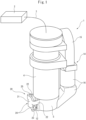
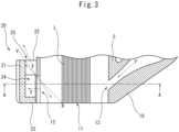
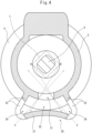
Fig. 1 is a perspective view of a phototherapy apparatus 1 according to an embodiment of the present invention,Fig. 2 is a perspective view of ashielding unit 20,Fig. 3 is a longitudinal sectional view of a distal end portion of the phototherapy apparatus 1, andFig. 4 is a transverse sectional view of the distal end portion of the phototherapy apparatus 1 taken along line A-A inFig. 3 . - The phototherapy apparatus 1 as a probe is electrically connected to a
control device 2 via acable 3. Thecontrol device 2 includes one or more processors, a storage unit, peripheral circuits thereof, and the like. Thecontrol device 2 comprehensively controls the overall operation of the phototherapy apparatus 1 on the basis of a computer program stored in advance in a storage unit. At the time of processing, thecontrol device 2 transmits, as appropriate, control signals related to emission and cessation of a laser, start and stopping of a fan, and the like. Thecontrol device 2 may include an input/output unit, for example, a display unit such as a display, or an input interface such as an operation button or a touch panel. The phototherapy apparatus 1, thecontrol device 2, thecable 3, the input interface, and the like may be collectively referred to as a phototherapy system. - The phototherapy apparatus 1 includes a
housing 4 having a tubular shape and alaser light source 6 disposed inside thehousing 4. Thehousing 4 includes amovable unit 5 having a cylindrical shape disposed at a distal end portion of thehousing 4 and movably disposable in an axial direction relative to thehousing 4. Thehousing 4 has a cylindrical shape having a circular cross section as a whole, but may be a member having a tubular shape having an elliptical cross section or may be a member having another shape such as, for example, a tubular shape having a polygonal cross section such as a square or an octagon. A target site is irradiated with the laser emitted from thelaser light source 6 through anopening 11 provided in a distal end surface of thehousing 4. - The
movable unit 5 functions as a contact-type interlock mechanism in the phototherapy apparatus 1. Specifically, the phototherapy apparatus 1 is configured to emit the laser only when themovable unit 5 is retracted by being pressed against the target site or the vicinity of the target site. In other words, the retraction of themovable unit 5 is detected by a sensor disposed inside thehousing 4, and thecontrol device 2, triggered by this detection, is configured to enable laser emission. This can prevent unintended laser emission. The phototherapy apparatus 1 need not include themovable unit 5. - An
exhaust port 12 which is a first opening is provided on a side surface of thehousing 4, specifically, on a side surface of themovable unit 5. Anintake port 13 which is a third opening is provided on the side surface of thehousing 4, specifically, on the side surface of themovable unit 5, on a side opposite to theexhaust port 12. Positions of theexhaust port 12 and theintake port 13 in thehousing 4 may be set as desired in the axial direction and a circumferential direction. - The phototherapy apparatus 1 includes an
air supply device 14 which supplies air to be injected into thehousing 4 from theintake port 13. Theair supply device 14 includes afan 15 disposed adjacent to the side surface of thehousing 4 and aduct 16 connecting thefan 15 and theintake port 13. Accordingly, air F taken in by rotation of thefan 15 is guided to theintake port 13 through theduct 16. The air F supplied into thehousing 4 through theintake port 13 removes heat from inside thehousing 4 and the target site heated by the laser emission, and is emitted outside thehousing 4 through theexhaust port 12. Furthermore, the air F emitted outside thehousing 4 is emitted outside the phototherapy apparatus 1 throughfirst vents 24 and asecond vent 25 described below. The phototherapy apparatus 1 need not include theair supply device 14 and theintake port 13. In this case, the air F heated by the emission of the laser inside the phototherapy apparatus 1 is emitted outside thehousing 4 from theexhaust port 12 by convection. Furthermore, to increase an exhaust efficiency by the convection, a plurality of theexhaust ports 12 may be provided in thehousing 4. - As described above, although not anticipated in a normal usage mode, an insertion having a rod shape and including a portion which reflects light, such as a mirror, may be inserted, for example, simply out of curiosity, into the
housing 4 through theexhaust port 12. Therefore, the phototherapy apparatus 1 further includes theshielding unit 20 provided integrally with the side surface of thehousing 4. - The
shielding unit 20 includes afirst shielding wall 21 and twosecond shielding walls 22 extending in the axial direction of thehousing 4, and abottom wall 23 provided flush with the distal end surface of thehousing 4. Thebottom wall 23 need not be flush with the distal end surface of thehousing 4 as long as thebottom wall 23 does not protrude from the distal end surface of thehousing 4. Thebottom wall 23 may include a bottom surface parallel to the distal end surface of thehousing 4 disposed rearward of the distal end surface of thehousing 4, or may be an inclined surface inclined rearward from an edge portion of the distal end surface of thehousing 4. Thefirst shielding wall 21 is disposed facing the side surface of thehousing 4, in particular, theexhaust port 12. A central portion of thefirst shielding wall 21 in a width direction, i.e., in the circumferential direction, is formed curved in a convex shape toward thehousing 4. In other words, thefirst shielding wall 21 is curved in a direction opposite to the side surface of thehousing 4. Each of the twosecond shielding walls 22 extends radially outward with respect to the axial direction from the side surface of thehousing 4. Distal end portions of the twosecond shielding walls 22 in a radial direction are continuously connected to end portions of thefirst shielding wall 21 in the circumferential direction. Connection portions between thefirst shielding wall 21 and thesecond shielding walls 22 are formed curving outward in a convex shape. - The two connection portions of the
first shielding wall 21 and thesecond shielding walls 22 on the distal end side and thecorresponding bottom wall 23 are cut out, defining the twofirst vents 24. Specifically, thefirst shielding wall 21 and thesecond shielding walls 22 are cut out, forming an end surface extending rearward in the axial direction from a distal end side of thehousing 4 and an end surface extending in the radial direction at a position away from the distal end of thehousing 4. Thus, the twofirst vents 24, substantially rectangular in shape, disposed on the distal end side of thehousing 4, and open in the circumferential direction, are defined in theshielding unit 20. Thebottom wall 23 need not be cut out, and only the two connection portions on the distal end side of thefirst shielding wall 21 and thesecond shielding wall 22 need be cut out so as to define the first vents 24. - Rear end surfaces of the
first shielding wall 21 and thesecond shielding walls 22 and the side surface of thehousing 4 define thesecond vent 25 disposed on the side surface of thehousing 4 and opening rearward. Thesecond vent 25 extends in the circumferential direction and has an elongated shape with a center narrowed by the curvature of thefirst shielding wall 21. The twofirst vents 24 and thesecond vent 25, by thefirst shielding wall 21, thesecond shielding walls 22, and thehousing 4, constitute a second opening which opens in the circumferential direction of thehousing 4 or rearward from thehousing 4. - In a use state in which treatment is performed using the phototherapy apparatus 1, a surface of the distal end portion of the phototherapy apparatus 1 including the
opening 11 which is the emission port of the laser abuts against the vicinity of the target site. Therefore, the laser is not directly visible through theopening 11 on a distal end side of the phototherapy apparatus 1. On the other hand, in the use state of the phototherapy apparatus 1, theexhaust port 12 is open toward outside the phototherapy apparatus 1. However, a position, a shape, and a size of the shieldingunit 20, specifically, each of thefirst vents 24 and thesecond vent 25, are set in relation to a position, a shape, and a size of theexhaust port 12 so that an optical path of the laser emitted from thelaser light source 6 inside thehousing 4 or the reflected light of the laser reflected inside thehousing 4 is not directly visible from outside the phototherapy apparatus 1. - In
Figs. 3 and4 , an optical path range of the laser is denoted by reference sign L. The optical path range L of the laser refers to a range of an inner space defined by an outermost contour of the emitted laser. InFig. 4 , a range surrounded by a dot dash line is the optical path range L of the laser. As illustrated inFig. 3 , a line of sight V from outside the phototherapy apparatus 1 through thesecond vent 25 is blocked by the side surface of thehousing 4 surrounding theexhaust port 12, and does not reach the optical path range L of the laser. Similarly, as illustrated inFig. 4 , a line of sight V from outside the phototherapy apparatus 1 through thefirst vents 24 is blocked by the side surface of thehousing 4 surrounding theexhaust port 12, and does not reach the optical path range L of the laser. - In short, the shielding
unit 20 is provided so that the optical path of the laser emitted from thelaser light source 6 is not directly visible from outside thehousing 4 through theexhaust port 12. In other words, the shieldingunit 20 is at least formed so that when a virtual straight line connecting any point in the optical path range L of the laser and any point of the edge portion defining theexhaust port 12 is drawn, the virtual straight line passes through the shieldingunit 20. As a result, even if an insertion having a rod shape and including a portion which reflects light is inserted into thehousing 4 from theexhaust port 12 through thefirst vent 24 or thesecond vent 25, the laser is not reflected outside the phototherapy apparatus 1. - With reference to
Figs. 3 and4 , a case in which an insertion having a curved shape and including a portion which reflects light can be inserted through theexhaust port 12 through thefirst vent 24 or thesecond ventilation hole 25, causing reflection of the laser, will be described. InFigs. 3 and4 , the reflected light R directed outward through theexhaust port 12 is blocked by the shieldingunit 20, particularly by thefirst shielding wall 21. Accordingly, the reflected light R is not visible from outside the phototherapy apparatus 1 through thefirst vents 24 or thesecond vent 25. In other words, even if an insertion having curved shape and including a portion which reflects light is inserted into thehousing 4 from theexhaust port 12 through thefirst vent 24 or thesecond vent 25, the laser is not reflected outside the phototherapy apparatus 1. - In short, the shielding
unit 20 is configured to deter insertion of an insertion from theexhaust port 12 and, even if such an insertion is inserted, block reflected light of the laser so that the reflected light is not emitted outside. Accordingly, the phototherapy apparatus 1 is configured so that, even if the laser is unintentionally reflected inside thehousing 4, the reflected light is not visible from the outside. - The air F emitted radially outward from the
exhaust port 12 is guided so as to be emitted outside from thefirst vents 24 by thefirst shielding wall 21 curved in a direction opposite to the side surface of thehousing 4, i.e., curved in a convex shape toward thehousing 4. Furthermore, the air F which remains is emitted outside from thesecond vent 25. Thefirst shielding wall 21, being curved in the direction opposite to the side surface of thehousing 4, can guide the air F more smoothly. The curvature of thefirst shielding wall 21 may correspond to part of a cylindrical surface with an axial line parallel to an axial line of thehousing 4, or may correspond to part of a convex curved surface such as a spherical surface, as long as the curvature can smoothly guide the air F. - In the embodiment described above, the shielding
unit 20 is provided integrally with thehousing 4, but may be configured separately from thehousing 4. In this case, the shieldingunit 20 may be configured to be attachable to and detachable from thehousing 4. In the embodiment described above, the phototherapy apparatus 1 includes a total of three vents, i.e., the twofirst vents 24 and the onesecond vent 25, but may include one or two of these vents, or may additionally include four or more vents. The positions, the shapes, and the sizes of the vents may be determined in accordance with an amount of air supplied from theintake port 13 or the like, in consideration of the reflection of the laser described above and the like. The shielding unit may also be provided not only for theexhaust port 12 but also for another first opening formed for a different purpose. -
- 1 Phototherapy apparatus
- 2 Control device
- 3 Cable
- 4 Housing
- 5 Movable unit
- 6 Laser light source
- 11 Opening
- 12 Exhaust port
- 13 Intake port
- 14 Air supply device
- 15 Fan
- 16 Duct
- 20 Shielding unit
- 21 First shielding wall
- 22 Second shielding wall
- 23 Bottom wall
- 24 First vent
- 25 Second vent
Claims (6)
- A phototherapy apparatus, comprising:a housing having a tubular shape;a laser light source disposed inside the housing and configured to irradiate a target site with a laser from a distal end of the housing;a first opening provided in a side surface of the housing; anda shielding unit provided outside the housing and thus blocking reflected light of the laser unintentionally reflected inside the housing and directed toward an outside through the first opening.
- The phototherapy apparatus according to claim 1, wherein the shielding unit is provided so that an optical path of the laser emitted from the laser light source is not directly visible from outside the housing through the first opening.
- The phototherapy apparatus according to claim 2, wherein the shielding unit is formed so that when a virtual straight line connecting any point in an optical path range of the laser and any point of an edge portion defining the first opening is drawn, the virtual straight line passes through the shielding unit.
- The phototherapy apparatus according to claim 3, whereinthe shielding unit includes a shielding wall extending in an axial direction of the housing, andthe shielding wall and the housing form at least one second opening which opens in a circumferential direction of the housing or rearward of the housing.
- The phototherapy apparatus according to claim 4, wherein the shielding wall faces the side surface of the housing and curves in a convex shape toward the housing.
- The phototherapy apparatus according to any one of claims 1 to 5, further comprising:a third opening provided in the side surface of the housing; andan air supply device configured to supply air into the housing through the third opening.
Applications Claiming Priority (2)
| Application Number | Priority Date | Filing Date | Title |
|---|---|---|---|
| JP2022095070 | 2022-06-13 | ||
| PCT/JP2023/021654 WO2023243577A1 (en) | 2022-06-13 | 2023-06-12 | Phototherapy apparatus |
Publications (2)
| Publication Number | Publication Date |
|---|---|
| EP4537897A1 true EP4537897A1 (en) | 2025-04-16 |
| EP4537897A4 EP4537897A4 (en) | 2026-04-08 |
Family
ID=89191227
Family Applications (1)
| Application Number | Title | Priority Date | Filing Date |
|---|---|---|---|
| EP23823867.9A Pending EP4537897A4 (en) | 2022-06-13 | 2023-06-12 | PHOTOGRAPHY DEVICE |
Country Status (6)
| Country | Link |
|---|---|
| EP (1) | EP4537897A4 (en) |
| JP (1) | JP7802170B2 (en) |
| KR (1) | KR20250007643A (en) |
| CN (1) | CN119365238A (en) |
| CA (1) | CA3259239A1 (en) |
| WO (1) | WO2023243577A1 (en) |
Family Cites Families (5)
| Publication number | Priority date | Publication date | Assignee | Title |
|---|---|---|---|---|
| JPS49146793U (en) * | 1973-04-13 | 1974-12-18 | ||
| KR101176851B1 (en) * | 2010-02-01 | 2012-08-27 | 연세대학교 산학협력단 | Cupping glass probe and device having the same |
| KR101865784B1 (en) | 2017-09-07 | 2018-06-08 | 주식회사 지티지웰니스 | Laser and handpiece to beak down fat in body |
| KR102144930B1 (en) * | 2018-03-09 | 2020-08-14 | (주)라메디텍 | Laser lancing device |
| KR102730593B1 (en) | 2019-12-23 | 2024-11-14 | 데이진 화-마 가부시키가이샤 | Light irradiation device |
-
2023
- 2023-06-12 WO PCT/JP2023/021654 patent/WO2023243577A1/en not_active Ceased
- 2023-06-12 CN CN202380046788.7A patent/CN119365238A/en active Pending
- 2023-06-12 EP EP23823867.9A patent/EP4537897A4/en active Pending
- 2023-06-12 CA CA3259239A patent/CA3259239A1/en active Pending
- 2023-06-12 JP JP2024528828A patent/JP7802170B2/en active Active
- 2023-06-12 KR KR1020247040656A patent/KR20250007643A/en active Pending
Also Published As
| Publication number | Publication date |
|---|---|
| KR20250007643A (en) | 2025-01-14 |
| JPWO2023243577A1 (en) | 2023-12-21 |
| CN119365238A (en) | 2025-01-24 |
| EP4537897A4 (en) | 2026-04-08 |
| JP7802170B2 (en) | 2026-01-19 |
| WO2023243577A1 (en) | 2023-12-21 |
| CA3259239A1 (en) | 2025-04-02 |
Similar Documents
| Publication | Publication Date | Title |
|---|---|---|
| US10564411B2 (en) | Illumination device and endoscope | |
| EP3630026B1 (en) | Illuminated infusion cannula | |
| US11278195B2 (en) | Illumination optical system | |
| EP4192337B1 (en) | Tumor ablation planning using interstitial optical mapping | |
| CN115068828B (en) | Skin treatment equipment | |
| ES2842203T3 (en) | System for femtofragmentation of a lens | |
| JP2002507461A (en) | Illumination device for use in ophthalmic microsurgery | |
| US12569297B2 (en) | Cooling for a personal care device | |
| CA2823714A1 (en) | Combined surgical endoprobe for optical coherence tomography, illumination or photocoagulation | |
| US20200360104A1 (en) | Light instrument for illuminating the intraocular space | |
| CN113950353A (en) | Light therapy diagnosis device and working method thereof | |
| JP7123978B2 (en) | Positioning device, system and method | |
| EP3053507A1 (en) | Medical probe | |
| CA3259239A1 (en) | PHOTOTHERAPY DEVICE | |
| US10018784B2 (en) | Fiber-optic device and process for manufacturing the device | |
| JP6553742B2 (en) | Illumination device and endoscope | |
| CA3148961C (en) | Phototherapy device | |
| JP2020069379A (en) | Medical laser light guide | |
| CN115087388B (en) | Endoscope | |
| US20140276691A1 (en) | Combination diffused and focused fiber optic for diagnosis and treatment of diseased cells | |
| EP2818097A1 (en) | Improved medical device | |
| EP4529858A1 (en) | Ultrasound probe | |
| WO2018071994A1 (en) | Fibre optic assembly | |
| JPH04221543A (en) | Laser probe | |
| CZ2001297A3 (en) | Light guiding device and method for making the same |
Legal Events
| Date | Code | Title | Description |
|---|---|---|---|
| STAA | Information on the status of an ep patent application or granted ep patent |
Free format text: STATUS: THE INTERNATIONAL PUBLICATION HAS BEEN MADE |
|
| PUAI | Public reference made under article 153(3) epc to a published international application that has entered the european phase |
Free format text: ORIGINAL CODE: 0009012 |
|
| STAA | Information on the status of an ep patent application or granted ep patent |
Free format text: STATUS: REQUEST FOR EXAMINATION WAS MADE |
|
| 17P | Request for examination filed |
Effective date: 20241212 |
|
| AK | Designated contracting states |
Kind code of ref document: A1 Designated state(s): AL AT BE BG CH CY CZ DE DK EE ES FI FR GB GR HR HU IE IS IT LI LT LU LV MC ME MK MT NL NO PL PT RO RS SE SI SK SM TR |
|
| DAV | Request for validation of the european patent (deleted) | ||
| DAX | Request for extension of the european patent (deleted) | ||
| A4 | Supplementary search report drawn up and despatched |
Effective date: 20260305 |
|
| RIC1 | Information provided on ipc code assigned before grant |
Ipc: A61N 5/067 20060101AFI20260227BHEP Ipc: A61B 18/20 20060101ALI20260227BHEP |