EP4537887A2 - System for expanding implants - Google Patents
System for expanding implants Download PDFInfo
- Publication number
- EP4537887A2 EP4537887A2 EP24215434.2A EP24215434A EP4537887A2 EP 4537887 A2 EP4537887 A2 EP 4537887A2 EP 24215434 A EP24215434 A EP 24215434A EP 4537887 A2 EP4537887 A2 EP 4537887A2
- Authority
- EP
- European Patent Office
- Prior art keywords
- inflatable body
- inflatable
- implant
- expandable implant
- shoulder portion
- Prior art date
- Legal status (The legal status is an assumption and is not a legal conclusion. Google has not performed a legal analysis and makes no representation as to the accuracy of the status listed.)
- Pending
Links
Images


Classifications
-
- A—HUMAN NECESSITIES
- A61—MEDICAL OR VETERINARY SCIENCE; HYGIENE
- A61F—FILTERS IMPLANTABLE INTO BLOOD VESSELS; PROSTHESES; DEVICES PROVIDING PATENCY TO, OR PREVENTING COLLAPSING OF, TUBULAR STRUCTURES OF THE BODY, e.g. STENTS; ORTHOPAEDIC, NURSING OR CONTRACEPTIVE DEVICES; FOMENTATION; TREATMENT OR PROTECTION OF EYES OR EARS; BANDAGES, DRESSINGS OR ABSORBENT PADS; FIRST-AID KITS
- A61F2/00—Filters implantable into blood vessels; Prostheses, i.e. artificial substitutes or replacements for parts of the body; Appliances for connecting them with the body; Devices providing patency to, or preventing collapsing of, tubular structures of the body, e.g. stents
- A61F2/02—Prostheses implantable into the body
- A61F2/24—Heart valves ; Vascular valves, e.g. venous valves; Heart implants, e.g. passive devices for improving the function of the native valve or the heart muscle; Transmyocardial revascularisation [TMR] devices; Valves implantable in the body
- A61F2/2427—Devices for manipulating or deploying heart valves during implantation
- A61F2/243—Deployment by mechanical expansion
- A61F2/2433—Deployment by mechanical expansion using balloon catheter
-
- A—HUMAN NECESSITIES
- A61—MEDICAL OR VETERINARY SCIENCE; HYGIENE
- A61F—FILTERS IMPLANTABLE INTO BLOOD VESSELS; PROSTHESES; DEVICES PROVIDING PATENCY TO, OR PREVENTING COLLAPSING OF, TUBULAR STRUCTURES OF THE BODY, e.g. STENTS; ORTHOPAEDIC, NURSING OR CONTRACEPTIVE DEVICES; FOMENTATION; TREATMENT OR PROTECTION OF EYES OR EARS; BANDAGES, DRESSINGS OR ABSORBENT PADS; FIRST-AID KITS
- A61F2/00—Filters implantable into blood vessels; Prostheses, i.e. artificial substitutes or replacements for parts of the body; Appliances for connecting them with the body; Devices providing patency to, or preventing collapsing of, tubular structures of the body, e.g. stents
- A61F2/95—Instruments specially adapted for placement or removal of stents or stent-grafts
- A61F2/958—Inflatable balloons for placing stents or stent-grafts
-
- A—HUMAN NECESSITIES
- A61—MEDICAL OR VETERINARY SCIENCE; HYGIENE
- A61F—FILTERS IMPLANTABLE INTO BLOOD VESSELS; PROSTHESES; DEVICES PROVIDING PATENCY TO, OR PREVENTING COLLAPSING OF, TUBULAR STRUCTURES OF THE BODY, e.g. STENTS; ORTHOPAEDIC, NURSING OR CONTRACEPTIVE DEVICES; FOMENTATION; TREATMENT OR PROTECTION OF EYES OR EARS; BANDAGES, DRESSINGS OR ABSORBENT PADS; FIRST-AID KITS
- A61F2/00—Filters implantable into blood vessels; Prostheses, i.e. artificial substitutes or replacements for parts of the body; Appliances for connecting them with the body; Devices providing patency to, or preventing collapsing of, tubular structures of the body, e.g. stents
- A61F2/02—Prostheses implantable into the body
- A61F2/24—Heart valves ; Vascular valves, e.g. venous valves; Heart implants, e.g. passive devices for improving the function of the native valve or the heart muscle; Transmyocardial revascularisation [TMR] devices; Valves implantable in the body
- A61F2/2412—Heart valves ; Vascular valves, e.g. venous valves; Heart implants, e.g. passive devices for improving the function of the native valve or the heart muscle; Transmyocardial revascularisation [TMR] devices; Valves implantable in the body with soft flexible valve members, e.g. tissue valves shaped like natural valves
- A61F2/2418—Scaffolds therefor, e.g. support stents
-
- A—HUMAN NECESSITIES
- A61—MEDICAL OR VETERINARY SCIENCE; HYGIENE
- A61F—FILTERS IMPLANTABLE INTO BLOOD VESSELS; PROSTHESES; DEVICES PROVIDING PATENCY TO, OR PREVENTING COLLAPSING OF, TUBULAR STRUCTURES OF THE BODY, e.g. STENTS; ORTHOPAEDIC, NURSING OR CONTRACEPTIVE DEVICES; FOMENTATION; TREATMENT OR PROTECTION OF EYES OR EARS; BANDAGES, DRESSINGS OR ABSORBENT PADS; FIRST-AID KITS
- A61F2/00—Filters implantable into blood vessels; Prostheses, i.e. artificial substitutes or replacements for parts of the body; Appliances for connecting them with the body; Devices providing patency to, or preventing collapsing of, tubular structures of the body, e.g. stents
- A61F2/95—Instruments specially adapted for placement or removal of stents or stent-grafts
- A61F2/958—Inflatable balloons for placing stents or stent-grafts
- A61F2002/9583—Means for holding the stent on the balloon, e.g. using protrusions, adhesives or an outer sleeve
-
- A—HUMAN NECESSITIES
- A61—MEDICAL OR VETERINARY SCIENCE; HYGIENE
- A61F—FILTERS IMPLANTABLE INTO BLOOD VESSELS; PROSTHESES; DEVICES PROVIDING PATENCY TO, OR PREVENTING COLLAPSING OF, TUBULAR STRUCTURES OF THE BODY, e.g. STENTS; ORTHOPAEDIC, NURSING OR CONTRACEPTIVE DEVICES; FOMENTATION; TREATMENT OR PROTECTION OF EYES OR EARS; BANDAGES, DRESSINGS OR ABSORBENT PADS; FIRST-AID KITS
- A61F2230/00—Geometry of prostheses classified in groups A61F2/00 - A61F2/26 or A61F2/82 or A61F9/00 or A61F11/00 or subgroups thereof
- A61F2230/0063—Three-dimensional shapes
- A61F2230/0067—Three-dimensional shapes conical
-
- A—HUMAN NECESSITIES
- A61—MEDICAL OR VETERINARY SCIENCE; HYGIENE
- A61F—FILTERS IMPLANTABLE INTO BLOOD VESSELS; PROSTHESES; DEVICES PROVIDING PATENCY TO, OR PREVENTING COLLAPSING OF, TUBULAR STRUCTURES OF THE BODY, e.g. STENTS; ORTHOPAEDIC, NURSING OR CONTRACEPTIVE DEVICES; FOMENTATION; TREATMENT OR PROTECTION OF EYES OR EARS; BANDAGES, DRESSINGS OR ABSORBENT PADS; FIRST-AID KITS
- A61F2250/00—Special features of prostheses classified in groups A61F2/00 - A61F2/26 or A61F2/82 or A61F9/00 or A61F11/00 or subgroups thereof
- A61F2250/0014—Special features of prostheses classified in groups A61F2/00 - A61F2/26 or A61F2/82 or A61F9/00 or A61F11/00 or subgroups thereof having different values of a given property or geometrical feature, e.g. mechanical property or material property, at different locations within the same prosthesis
- A61F2250/0039—Special features of prostheses classified in groups A61F2/00 - A61F2/26 or A61F2/82 or A61F9/00 or A61F11/00 or subgroups thereof having different values of a given property or geometrical feature, e.g. mechanical property or material property, at different locations within the same prosthesis differing in diameter
-
- A—HUMAN NECESSITIES
- A61—MEDICAL OR VETERINARY SCIENCE; HYGIENE
- A61M—DEVICES FOR INTRODUCING MEDIA INTO, OR ONTO, THE BODY; DEVICES FOR TRANSDUCING BODY MEDIA OR FOR TAKING MEDIA FROM THE BODY; DEVICES FOR PRODUCING OR ENDING SLEEP OR STUPOR
- A61M25/00—Catheters; Hollow probes
- A61M25/10—Balloon catheters
- A61M25/1002—Balloon catheters characterised by balloon shape
-
- A—HUMAN NECESSITIES
- A61—MEDICAL OR VETERINARY SCIENCE; HYGIENE
- A61M—DEVICES FOR INTRODUCING MEDIA INTO, OR ONTO, THE BODY; DEVICES FOR TRANSDUCING BODY MEDIA OR FOR TAKING MEDIA FROM THE BODY; DEVICES FOR PRODUCING OR ENDING SLEEP OR STUPOR
- A61M25/00—Catheters; Hollow probes
- A61M25/10—Balloon catheters
- A61M25/1011—Multiple balloon catheters
Definitions
- Implants may be deployed to the desired portion of the patient's body percutaneously, in a minimally invasive manner. Such deployment may occur transcatheter, in which a catheter may be deployed through the vasculature of an individual.
- the inflatable body 16 (or second or distal inflatable body), similar to the inflatable body 14, may include an outer wall 42 forming an outer surface 44 of the inflatable body 16.
- the outer surface 44 of the inflatable body 16 may be configured to apply an expansion force to the expandable implant 12.
- the inflatable body 16 may have a first end 46 and a second end 48.
- the first end 46 and second end 48 may each be coupled to the elongate shaft 26 of the delivery apparatus for the expandable implant 12.
- the inflatable body 16 may extend axially along the length of the elongate shaft 26 of the delivery apparatus in both a deflated state as shown in FIGS. 1-2 and in an inflated state as shown in FIGS. 3-4 .
- the inflatable body 16 may extend radially outward from the elongate shaft 26 when in an inflated state, and may extend around the axis of the elongate shaft 26.
- the inflatable body 16 may have a conical frustum shape as shown in FIG. 5 for example when in an inflated state, or may have another shape as desired.
- An inflation lumen 56 may be provided for passing fluid into the interior chamber 54 of the inflatable body 16.
- the inflation lumen 56 may extend along the elongate shaft 26 and may have a proximal end that couples to a port 92 (as shown in FIG. 10 ) for passing fluid into and out of the inflation lumen, and may have a distal end with an opening for passing fluid into and out of the interior chamber 54 of the inflatable body 16.
- the inflation lumen 56 may be configured to extend around an interior shaft 58 (e.g., a guide wire lumen) of the elongate shaft 26, with the inflation lumen 40 extending around and concentric with the inflation lumen 56.
- the configuration of the inflation lumen 56 may be varied in other embodiments.
- a portion of one of the inflatable bodies 14, 16 may overlap a portion of another of the inflatable bodies 14, 16.
- the first end 22 of the first inflatable body 14 may comprise an overlap portion that overlaps the second inflatable body 16.
- the first end 22 overlaps and couples to the narrow portion 32 of the second inflatable body 16.
- the shoulder portion 30 of the first inflatable body 14 further comprises an overlap portion that overlaps the second end 48 of the second inflatable body 16.
- the overlap of the first inflatable body 14 over the second inflatable body 16 may allow the first inflatable body 14 to increase in size along with the inflation of the second inflatable body 16. For example, as shown in FIGS.
- the expandable implant 12 may comprise an implant 12 configured to be radially expanded outward via an expansion force applied by the inflatable body 16.
- FIG. 6 illustrates a side view of such an implant 12, including a frame 60 that is configured to allow the expandable implant 12 to expand.
- the frame 60 may be configured as a plurality of struts coupled to each other with spaces between the struts.
- the frame 60 may be configured such that as the implant 12 is expanded radially outward (for example in a direction shown by the arrows 62 extending outward from the implant axis 64) the length 66 of the implant 12 may shorten.
- the frame 60 may be configured such that as the implant 12 is radially compressed, the length 66 of the implant 12 may increase.
- the implant 12 may be configured to shorten in a direction.
- the implant 12 as shown in FIG. 6 may include a first end 68 and a second end 70.
- the second end 70 for example, being maintained in a position and the first end 68 being free to move, an expansion force against the implant 12 will cause the length 66 of the implant 12 to shorten in a direction towards the second end 70 (with the first end 68 moving towards the second end 70).
- an expansion force against the implant 12 will cause the length 66 of the implant 12 to shorten in a direction towards the first end 68 (with the second end 70 moving towards the first end 68).
- the expandable implant 12 may have a variety of forms.
- the expandable implant 12 may be utilized as a prosthetic heart valve, which may be utilized for implantation in the native aortic, mitral, tricuspid, or pulmonary valves.
- Other forms of expandable implants may be utilized, including stents or other implants.
- the expandable implant 12 may be configured to have a tapered profile.
- FIG. 7 illustrates a cross sectional view of the implant 12.
- the implant 12 has an angled interior profile that faces an interior cavity 72 of the implant 12.
- the second end 70 is narrower than the first end 68 and the implant 12 has an inner surface 74 forming an angled interior profile from the first end 68 to the second end 70.
- the implant 12 may be considered a "V" shaped implant or otherwise an implant having a conical frustum interior shape, or may comprise another form of frustum in other embodiments (e.g., pyramidal or another shape).
- the implant may have an outer profile that is the same as the interior profile, or may be different in other embodiments.
- An implant 12 comprising a "V" shaped implant may have a variety of benefits, including having the prosthetic heart valve leaflets open in a direction towards the wide end (e.g., first end 68) of the implant 12.
- the prosthetic heart valve leaflets accordingly may have a reduced possibility of contacting the inner surface 74 of the implant 12 upon the leaflets moving to the open state.
- Other benefits may be provided as desired.
- An issue that may arise upon expanding expandable implants, particularly implants that are expandable with an inflatable body, is producing desired positioning of the expandable implants upon the inflatable body. This issue may produce difficulties in positioning the implant relative to the desired implantation site, and may produce difficulties in producing a desired size of expansion of the expandable implant. This issue may be enhanced with "V" shaped implants, as the "V" shaped implants may slip upon the inflatable body and produce an undesired position of the implant upon the inflatable body. Further, "V" shaped implants may have an expansion size that depends on the position of the implant upon the inflatable body. The system 10 as disclosed herein may reduce the possibility of such issues arising, and may improve the positioning of the expandable implants upon one or more inflatable bodies.
- the shoulder portion 30 of the first inflatable body 14 is positioned adjacent to the second end 70 of the expandable implant 12.
- the shoulder portion 30 may comprise a protrusion extending radially outward from the elongate shaft 26 of the delivery apparatus.
- the shoulder portion 30 may accordingly maintain the position of the second end 70 of the expandable implant 12, with the second end 70 of the expandable implant 12 impeded from sliding in a direction towards the inflatable body 14.
- the shoulder portion 30 may contact the second end 70 of the expandable implant 12 to impede movement in the direction towards the inflatable body 14.
- the shoulder portion 30 may have a diameter that is greater than a diameter of the implant 12 as shown in FIG. 1 .
- the expandable implant 12 may be delivered to a desired location within a patient's body such as an implantation site while being positioned upon the second inflatable body 16, and with the system 10 in the configuration shown in FIG. 1 .
- the elongate shaft 26 may be moved to the desired implantation site as shown, for example in FIGS. 11-13 , or via another method as desired.
- the first inflatable body 14 may be inflated as shown in FIG. 2 .
- fluid may be passed through the inflation lumen 40 and into the interior chamber 38 of the first inflatable body 14.
- the first inflatable body 14 may be in an inflated state, and may have an increased outer diameter 28 of the inflatable body 14.
- the size of the shoulder portion 30 may further increase.
- the shoulder portion 30 may continue to maintain the position of the second end 70 of the expandable implant 12, by continuing to impede movement of the second end 70 of the expandable implant 12 in a direction towards the first inflatable body 14.
- the second end 70 of the expandable implant 12 may remain in contact with the surface of the shoulder portion 30.
- the second inflatable body 16 may be at least partially inflated.
- FIG. 3 illustrates the second inflatable body 16 in an inflated state, being partially inflated. Fluid may be passed through the inflation lumen 56 and into the interior chamber 54 of the second inflatable body 16 to inflate the second inflatable body 16.
- the shoulder portion 50 of the second inflatable body 16 may be configured to first inflate, with inflation continuing in a direction towards the first inflatable body 14. The increased diameter of the shoulder portion 50 may impede movement of the first end 68 of the expandable implant 12 in a direction away from the first inflatable body 14. Further, the tapered shape of the outer surface 44 of the second inflatable body 16 may cause the outer surface 44 to apply an expansion force against the expandable implant 12 causing the first end 68 of the expandable implant 12 to move towards the first inflatable body 14.
- the tapered shape of the outer surface 44 includes a narrow portion 32 having a diameter 52.
- the diameter 28 of the first inflatable body 14 is greater than the diameter 52 of the narrow portion 32, thus allowing the first inflatable body 14 to maintain the position of the second end 70 of the expandable implant 12.
- FIG. 5 illustrates a perspective view of the system 10 in the configuration shown in FIG. 4 , with the expandable implant 12 excluded from view for clarity.
- the first inflatable body 14 is shown to have a bulb shape
- the second inflatable body 16 is shown to have a conical frustum shape.
- FIG. 8 illustrates a side cross sectional view of an embodiment of the system in which the positions of the first inflatable body 14 and the second inflatable body 16 are reversed from the positions shown in FIG. 1 upon the elongate shaft 26 of the delivery apparatus.
- the second inflatable body 16 may be positioned proximal and the first inflatable body 14 may be positioned distal.
- Such a reversed configuration may allow for a different delivery orientation of the expandable implant 12 to the desired implantation site.
- the wide end 68 of the expandable implant 12 may be positioned proximal and the narrow end 70 may be positioned distal.
- Such a reversed configuration may also allow for a different direction of delivery approach to the implantation site.
- one configuration may allow for a transvascular approach (e.g., over the aortic arch) and another reversed configuration may allow for a transapical approach.
- Various other approaches may be utilized for an implantation site as desired.
- first inflatable body and the second inflatable body are comprised of a unitary body.
- the first inflatable body may be made of a material that more easily inflates than the second inflatable body.
- the first inflatable body may then inflate first, due to the relatively reduced force at which the first inflatable body inflates.
- the resistance to inflation of the first inflatable body may increase, and thus the second inflatable body may begin to expand due to inflation.
- the second inflatable body may then inflate until it reaches its maximum size.
- the first inflatable body and second inflatable body may utilize a single fluid chamber and a single inflation lumen may be utilized.
- the sequence of the first inflatable body being inflated first and the second inflatable body being inflated second may be maintained due to the different materials of the first inflatable body and the second inflatable body, or other configuration of the bodies.
- portions of the first inflatable body and second inflatable body may be covered with materials.
- coatings or other coverings may be positioned over the inflatable bodies.
- a coating may cover the outer surface of the second inflatable body, yet the outer surface may apply an expansion force to the expandable implant through the coating.
- FIG. 10 illustrates a delivery apparatus 80 that may be utilized to deliver the expandable implant 12 to a location in a patient's body.
- the delivery apparatus 80 may include the elongate shaft 26, which may have a distal portion 82 and a proximal portion 84.
- the system 10 including the inflatable bodies 14, 16 may be positioned on the distal portion 82 of the elongate shaft 26.
- the elongate shaft 26 may include a nose cone 86, which may couple to an interior shaft 58 of the elongate shaft 26 (as shown in FIGS. 1-4 ).
- a proximal end of the delivery apparatus 80 may include a port 92 for passing fluid into and out of one or more of the inflation lumens 40, 56.
- FIG. 11 illustrates a step in a method of replacing an aortic heart valve.
- a delivery apparatus 80 for example as shown in FIG. 10 may be utilized to approach the native aortic heart valve 94.
- the elongate shaft 26 may be deflected to allow the "V" shaped implant 12 to approach the native aortic heart valve 94 through the aortic arch.
- the system may be advanced to position the expandable implant 12 in the desired implantation location.
- the first inflatable body 14 may first be inflated to a diameter as described in regard to FIG. 2 .
- the first inflatable body 14 may include the shoulder portion 30 that may impede movement of the narrow end 70 of the implant 12 in the distal direction. As such, the narrow end 70 of the implant 12 may be aligned and positioned with a desired implantation location for the implant 12.
- the delivery apparatus and apparatuses and the systems disclosed herein may be used in a variety of procedures, which may include transcatheter aortic valve implantation (TAVI).
- TAVI transcatheter aortic valve implantation
- the delivery apparatus and the systems disclosed herein may be utilized for transarterial access, including transfemoral access, to a patient's heart.
- the delivery apparatus may be utilized for mitral, tricuspid, and pulmonary replacement and repair as well.
- the delivery systems may be utilized in transcatheter percutaneous procedures, including transarterial procedures, which may be transfemoral or transjugular. Transapical procedures, among others, may also be utilized.
- Methods as disclosed herein may be utilized in locations that do not utilize native valves, including a pulmonary artery and in the vena cava, among other locations (other arteries, blood vessels, or other vasculature of a patient's body, among other portions of a patient's body).
- An implant such as a stent or other form of implant may be delivered to such portions of the patient's body.
- the methods herein are not limited to the methods specifically described, and may include methods of utilizing the systems and apparatuses disclosed herein.
Landscapes
- Health & Medical Sciences (AREA)
- Engineering & Computer Science (AREA)
- Cardiology (AREA)
- Biomedical Technology (AREA)
- Vascular Medicine (AREA)
- Transplantation (AREA)
- Oral & Maxillofacial Surgery (AREA)
- Heart & Thoracic Surgery (AREA)
- Life Sciences & Earth Sciences (AREA)
- Animal Behavior & Ethology (AREA)
- General Health & Medical Sciences (AREA)
- Public Health (AREA)
- Veterinary Medicine (AREA)
- Mechanical Engineering (AREA)
- Prostheses (AREA)
- Media Introduction/Drainage Providing Device (AREA)
Abstract
Description
- This application claims the benefit of and priority to
U.S. Provisional Patent Application Serial No. 63/038,035, filed on June 11, 2020 - A variety of maladies may affect an individual's body. Such maladies may be of the individual's heart, and may include maladies of the individual's heart valves, including the aortic, mitral, tricuspid, and pulmonary valves. Stenosis, for example, is a common and serious valve disease that may affect the operation of the heart valves and an individual's overall well-being.
- Implants may be provided that may replace or repair portions of a patient's heart. Prosthetic implants, such as prosthetic heart valves, may be provided to replace a portion of a patient's heart. Prosthetic aortic, mitral, tricuspid, and even pulmonary valves may be provided.
- Implants may be deployed to the desired portion of the patient's body percutaneously, in a minimally invasive manner. Such deployment may occur transcatheter, in which a catheter may be deployed through the vasculature of an individual.
- During deployment of such implants, the implants must be expanded to provide an expanded configuration for such implant. Care must be taken to properly expand the implants to a desired implantation site, and to avoid over expansion or under expansion of such implants.
- Expandable implants may be expanded by inflatable bodies, which may comprise balloons or another form of inflatable body. Upon expansion of the expandable implants by the inflatable bodies, care must be taken to assure that the expandable implant is positioned in the desired location upon the inflatable body, to provide the desired implantation location and expansion size of the expandable implant. These concerns may be increased with "V" shaped implants, as "V" shaped implants might slip upon the inflatable body and produce an undesired position of the implant upon the inflatable body. Further, "V" shaped implants may have an expansion size that depends on the position of the implant upon an inflatable body.
- Embodiments disclosed herein may be directed to improved positioning of an expandable implant upon one or more inflatable bodies upon expansion of the inflatable bodies. Embodiments may be utilized with a "V" shaped implant. Embodiments as disclosed herein may include a system for expansion of an expandable implant. The system may include a first inflatable body having a first outer diameter when in an inflated state. The system may include a second inflatable body positioned adjacent to the first inflatable body and having an outer surface configured to apply an expansion force to the expandable implant and having a shape that tapers downward in a direction towards the first inflatable body to a narrow portion having a second outer diameter that is less than the first outer diameter when the second inflatable body is in an inflated state.
- Embodiments as disclosed herein may include a delivery system for an expandable implant. The delivery system may include a delivery apparatus configured to deliver the expandable implant to a location in a patient's body. The delivery apparatus may include an elongate shaft and a first inflatable body coupled to the elongate shaft and having a first outer diameter when in an inflated state. The delivery apparatus may include a second inflatable body coupled to the elongate shaft adjacent to the first inflatable body and having an outer surface configured to apply an expansion force to the expandable implant and having a shape that tapers downward in a direction towards the first inflatable body to a narrow portion having a second outer diameter that is less than the first outer diameter when the second inflatable body is in an inflated state.
- Embodiments as disclosed herein may include a method. The method may include inflating a first inflatable body. The method may include radially expanding an expandable implant positioned around an outer surface of a second inflatable body by inflating the second inflatable body, the second inflatable body being positioned adjacent to the first inflatable body and having an outer surface having a shape that tapers downward in a direction towards the first inflatable body to a narrow portion, with an outer diameter of the narrow portion being less than an outer diameter of the first inflatable body.
- These and other features, aspects, and advantages are described below with reference to the drawings, which are intended to illustrate, but not to limit, the disclosure. In the drawings, like reference characters denote corresponding features consistently throughout similar embodiments.
-
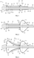
FIG. 1 is a cross sectional view of a system for expansion of an expandable implant according to an embodiment of the present disclosure. -
FIG. 2 is a cross sectional view of the system shown inFIG. 1 , with an inflatable body inflated. -
FIG. 3 is a cross sectional view of the system shown inFIG. 1 , with two inflatable bodies inflated. -
FIG. 4 is a cross sectional view of the system shown inFIG. 1 , with two inflatable bodies inflated. -
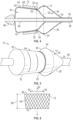
FIG. 5 is a perspective view of the system shown inFIG. 4 , with the implant removed from view. -
FIG. 6 is a side view of an expandable implant according to an embodiment of the present disclosure. -
FIG. 7 is a cross sectional view of the expandable implant shown inFIG. 6 according to an embodiment of the present disclosure. -
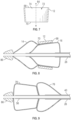
FIG. 8 is a cross sectional view of a system for expansion of an expandable implant according to an embodiment of the present disclosure. -
FIG. 9 is a cross sectional view of a system for expansion of an expandable implant according to an embodiment of the present disclosure. -
FIG. 10 is a side view of a delivery apparatus according to an embodiment of the present disclosure. -
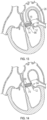
FIG. 11 is a schematic view of a delivery apparatus approaching an aortic valve. -
FIG. 12 is a schematic view of a system for expansion of an expandable implant having an inflatable body inflated. -
FIG. 13 is a schematic view of the system for expansion of an expandable implant shown inFIG. 12 having two inflatable bodies inflated. -
FIG. 14 is a schematic view of a deployed implant according to an embodiment of the present disclosure. - The following description and examples illustrate some example embodiments of the disclosure in detail. Those of skill in the art will recognize that there are numerous variations and modifications of the disclosure that are encompassed by its scope. Accordingly, the description of a certain example embodiment should not be deemed to limit the scope of the present disclosure.
-
FIG. 1 illustrates a side cross sectional view of asystem 10 for expansion of anexpandable implant 12. The system may include aninflatable body 14, which may be referred to as a first or proximal inflatable body, and may include aninflatable body 16, which may be referred to as a second or distal inflatable body. - The
inflatable body 14 may include anouter wall 18 forming anouter surface 20 of theinflatable body 14. Theinflatable body 14 may have afirst end 22 and asecond end 24. Thefirst end 22 may be coupled to a portion of the secondinflatable body 16, and thesecond end 24 may be coupled to anelongate shaft 26 of a delivery apparatus configured to deliver theexpandable implant 12 to a location in a patient's body. Theinflatable body 14 may extend axially along the length of theelongate shaft 26 of the delivery apparatus in both a deflated state as shown inFIG. 1 and in an inflated state as shown inFIGS. 2-4 . - The
inflatable body 14 may be configured to have a rounded profile when in an inflated state. Such a profile is shown for example inFIGS. 2-4 . Theinflatable body 14 may extend radially outward from theelongate shaft 26 when in an inflated state, and may extend around the axis of theelongate shaft 26. Theinflatable body 14 may have a bulb shape as shown inFIG. 5 for example when in an inflated state, or may have another shape as desired. Theinflatable body 14 may have an outer diameter 28 (as shown inFIGS. 2-4 ) when in an inflated state. - The
inflatable body 14 may be configured to have ashoulder portion 30. Theshoulder portion 30 may be positioned proximate to anarrow portion 32 of the second inflatable body 16 (as marked inFIGS. 3 and4 ). When theinflatable body 14 is in a deflated state, as shown inFIG. 1 , for example, theshoulder portion 30 may comprise a bump formed by theouter wall 18 of theinflatable body 14. The bump may be formed by theouter wall 18 being a folded portion, as shown inFIG. 1 , or theouter wall 18 may include a thicker portion at theshoulder portion 30 to form the bump in embodiments as desired. As shown inFIGS. 2-4 , as theinflatable body 14 is inflated, theshoulder portion 30 may form an outwardly extending and curved surface extending to an apex 34 of theinflatable body 14. Theinflatable body 14 may include a downwardly taperingportion 36 on the opposite side of the apex 34, extending downward to thesecond end 24 of theinflatable body 14. - The
outer wall 18 of theinflatable body 14 may surround aninterior chamber 38 of theinflatable body 14 that may be configured to hold fluid (for example, a liquid or other fluid in embodiments) for inflating theinflatable body 14. Theinterior chamber 38 may comprise a single chamber as shown inFIGS. 1-4 , or a plurality of chambers utilized to hold fluid for inflating theinflatable body 14. Theinterior chamber 38 may be sealed from outside of theinflatable body 14 by the coupling of theends inflatable body 14 to theinflatable body 16 and theelongate shaft 26, respectively. - An
inflation lumen 40 may be provided for passing fluid into theinterior chamber 38 of theinflatable body 14. Theinflation lumen 40 may extend along theelongate shaft 26 and may have a proximal end that couples to a port 92 (as shown inFIG. 10 ) for passing fluid into and out of theinflation lumen 40, and may have a distal end with an opening for passing fluid into and out of theinterior chamber 38 of theinflatable body 14. The configuration of theinflation lumen 40 may be varied in other embodiments. - The inflatable body 16 (or second or distal inflatable body), similar to the
inflatable body 14, may include anouter wall 42 forming anouter surface 44 of theinflatable body 16. Theouter surface 44 of theinflatable body 16 may be configured to apply an expansion force to theexpandable implant 12. Theinflatable body 16 may have afirst end 46 and asecond end 48. Thefirst end 46 andsecond end 48 may each be coupled to theelongate shaft 26 of the delivery apparatus for theexpandable implant 12. Theinflatable body 16 may extend axially along the length of theelongate shaft 26 of the delivery apparatus in both a deflated state as shown inFIGS. 1-2 and in an inflated state as shown inFIGS. 3-4 . - The
inflatable body 16 may extend radially outward from theelongate shaft 26 when in an inflated state, and may extend around the axis of theelongate shaft 26. Theinflatable body 16 may have a conical frustum shape as shown inFIG. 5 for example when in an inflated state, or may have another shape as desired. - The
inflatable body 16 may include ashoulder portion 50 that may be positioned proximate thefirst end 46 of theinflatable body 16. When theinflatable body 16 is in a deflated state, as shown inFIG. 1 , for example, theshoulder portion 50 may comprise a bump formed by theouter wall 42 of theinflatable body 16. The bump may be formed by theouter wall 42 being a folded portion, as shown inFIG. 1 , or theouter wall 42 may include a thicker portion at theshoulder portion 50 to form the bump in embodiments as desired. As shown inFIGS. 2-4 , as theinflatable body 16 is inflated, theshoulder portion 50 may form an outwardly extending and curved surface that is positioned offset from theexpandable implant 12. Theshoulder portion 50 may include a surface extending from an apex 53 of theinflatable body 16 in a direction towards thesecond end 48 of theinflatable body 16. Theinflatable body 16 may include a downwardly taperingportion 65 on the opposite side of the apex 53, extending downward to thefirst end 46 of theinflatable body 16. - The
outer surface 44 of the inflatable body may have a shape that tapers downward in a direction towards theinflatable body 14 to a narrow portion 32 (as marked inFIGS. 3 and4 ) when theinflatable body 16 is in an inflated state. Thenarrow portion 32 may have an outer diameter 52 (as shown inFIGS. 3 and4 ) when in an inflated state. Theouter diameter 52 of thenarrow portion 32 may be less than theouter diameter 28 of theinflatable body 14. - The
outer wall 42 of theinflatable body 16 may surround aninterior chamber 54 of theinflatable body 16 that may be configured to hold fluid (for example, a liquid or other fluid in embodiments) for inflating theinflatable body 16. Theinterior chamber 54 may comprise a single chamber as shown inFIGS. 1-4 , or a plurality of chambers utilized to hold fluid for inflating theinflatable body 16. Theinterior chamber 54 may be sealed from outside of theinflatable body 16 and from theinterior chamber 38 of theinflatable body 14 by the coupling of theends inflatable body 16 to theshaft 26. - An
inflation lumen 56 may be provided for passing fluid into theinterior chamber 54 of theinflatable body 16. Theinflation lumen 56 may extend along theelongate shaft 26 and may have a proximal end that couples to a port 92 (as shown inFIG. 10 ) for passing fluid into and out of the inflation lumen, and may have a distal end with an opening for passing fluid into and out of theinterior chamber 54 of theinflatable body 16. Theinflation lumen 56 may be configured to extend around an interior shaft 58 (e.g., a guide wire lumen) of theelongate shaft 26, with theinflation lumen 40 extending around and concentric with theinflation lumen 56. The configuration of theinflation lumen 56 may be varied in other embodiments. - Each
inflatable body respective chambers respective chambers inflatable bodies inflatable bodies inflatable bodies FIGS. 4 and 5 for example, and may then be inflated to that shape. In embodiments, theinflatable bodies inflatable bodies FIGS. 4 and 5 or may otherwise be configured to form the shapes shown inFIGS. 4 and 5 . - The
inflatable bodies inflatable bodies elongate shaft 26. Theinflatable bodies inflatable body 14 positioned proximal along the length of theelongate shaft 26 and the secondinflatable body 16 positioned distal along the length of theelongate shaft 26 as shown inFIGS. 1-5 for example. In embodiments, theinflatable bodies inflatable body 14 positioned distal along the length of theelongate shaft 26 and the secondinflatable body 16 positioned proximal along the length of theelongate shaft 26 as shown inFIG. 8 for example. Theinflatable bodies inflatable bodies inflatable bodies - In an embodiment as shown in
FIGS. 1-5 , a portion of one of theinflatable bodies inflatable bodies FIG. 1 , thefirst end 22 of the firstinflatable body 14 may comprise an overlap portion that overlaps the secondinflatable body 16. Thefirst end 22 overlaps and couples to thenarrow portion 32 of the secondinflatable body 16. Theshoulder portion 30 of the firstinflatable body 14 further comprises an overlap portion that overlaps thesecond end 48 of the secondinflatable body 16. The overlap of the firstinflatable body 14 over the secondinflatable body 16 may allow the firstinflatable body 14 to increase in size along with the inflation of the secondinflatable body 16. For example, as shown inFIGS. 3 and4 , thefirst end 22 of the firstinflatable body 14 is coupled to thenarrow portion 32 of the secondinflatable body 16 such that an inflation of thenarrow portion 32 causes thefirst end 22 of the firstinflatable body 14 to increase in size. In other embodiments, for example as shown inFIG. 9 , the inflatable bodies may not be coupled to each other. - The
expandable implant 12 may comprise animplant 12 configured to be radially expanded outward via an expansion force applied by theinflatable body 16.FIG. 6 , for example, illustrates a side view of such animplant 12, including aframe 60 that is configured to allow theexpandable implant 12 to expand. Theframe 60 may be configured as a plurality of struts coupled to each other with spaces between the struts. Theframe 60 may be configured such that as theimplant 12 is expanded radially outward (for example in a direction shown by thearrows 62 extending outward from the implant axis 64) thelength 66 of theimplant 12 may shorten. In addition, theframe 60 may be configured such that as theimplant 12 is radially compressed, thelength 66 of theimplant 12 may increase. - Notably, the
implant 12 may be configured to shorten in a direction. For example, theimplant 12 as shown inFIG. 6 may include afirst end 68 and asecond end 70. Upon thesecond end 70, for example, being maintained in a position and thefirst end 68 being free to move, an expansion force against theimplant 12 will cause thelength 66 of theimplant 12 to shorten in a direction towards the second end 70 (with thefirst end 68 moving towards the second end 70). Similarly, if thefirst end 68 were maintained in a position and thesecond end 70 were free to move, an expansion force against theimplant 12 will cause thelength 66 of theimplant 12 to shorten in a direction towards the first end 68 (with thesecond end 70 moving towards the first end 68). - The
expandable implant 12 may have a variety of forms. For example, theexpandable implant 12 may be utilized as a prosthetic heart valve, which may be utilized for implantation in the native aortic, mitral, tricuspid, or pulmonary valves. Other forms of expandable implants may be utilized, including stents or other implants. - The
expandable implant 12 may be configured to have a tapered profile.FIG. 7 , for example, illustrates a cross sectional view of theimplant 12. Features of the implant are not shown for clarity. For example, prosthetic heart valve leaflets may not be shown inFIG. 7 for clarity in an embodiment in which theimplant 12 is a prosthetic heart valve. Theimplant 12 has an angled interior profile that faces aninterior cavity 72 of theimplant 12. Thesecond end 70 is narrower than thefirst end 68 and theimplant 12 has aninner surface 74 forming an angled interior profile from thefirst end 68 to thesecond end 70. Theimplant 12 may be considered a "V" shaped implant or otherwise an implant having a conical frustum interior shape, or may comprise another form of frustum in other embodiments (e.g., pyramidal or another shape). The implant may have an outer profile that is the same as the interior profile, or may be different in other embodiments. - An
implant 12 comprising a "V" shaped implant may have a variety of benefits, including having the prosthetic heart valve leaflets open in a direction towards the wide end (e.g., first end 68) of theimplant 12. The prosthetic heart valve leaflets accordingly may have a reduced possibility of contacting theinner surface 74 of theimplant 12 upon the leaflets moving to the open state. Other benefits may be provided as desired. - In embodiments, implants other than "V" shaped implants may be utilized. For example, a cylindrical shaped implant or other shape of implant may be utilized, which may be expanded to a tapered profile via use of the
system 10 shown inFIG. 1 . - An issue that may arise upon expanding expandable implants, particularly implants that are expandable with an inflatable body, is producing desired positioning of the expandable implants upon the inflatable body. This issue may produce difficulties in positioning the implant relative to the desired implantation site, and may produce difficulties in producing a desired size of expansion of the expandable implant. This issue may be enhanced with "V" shaped implants, as the "V" shaped implants may slip upon the inflatable body and produce an undesired position of the implant upon the inflatable body. Further, "V" shaped implants may have an expansion size that depends on the position of the implant upon the inflatable body. The
system 10 as disclosed herein may reduce the possibility of such issues arising, and may improve the positioning of the expandable implants upon one or more inflatable bodies. - Referring to
FIG. 1 , theinflatable bodies expandable implant 12 is shown crimped onto theouter surface 44 of theinflatable body 16 and positioned around theouter surface 44. Theexpandable implant 12 may extend longitudinally along the axis of theelongate shaft 26 and over theinflatable body 16. Theexpandable implant 12 may be crimped upon theinflatable body 16 with a cylindrical outer shape, and with the first end 68 (the wide end as shown inFIG. 6 ) of theimplant 12 positioned proximate theshoulder portion 50 of the secondinflatable body 16 and the second end 70 (the narrow end as shown inFIG. 6 ) of theimplant 12 positioned proximate theshoulder portion 30 of the firstinflatable body 14. Theexpandable implant 12 may be in a compressed state and thus may have a length that is greater than a length of theexpandable implant 12 in an expanded state. - The first
inflatable body 14 may be positioned axially offset from theexpandable implant 12. Thefirst end 22 of the firstinflatable body 14 may however be sandwiched between thesecond end 70 of theexpandable implant 12 and the secondinflatable body 16 as shown inFIG. 1 . Theshoulder portion 50 of the secondinflatable body 16 may be axially offset from theexpandable implant 12. As such, theimplant 12 may not cover a portion of the firstinflatable body 14 or the secondinflatable body 16 in embodiments, with a portion of the firstinflatable body 14 or the secondinflatable body 16 being axially offset from theimplant 12. - With the
inflatable bodies FIG. 1 , theshoulder portion 30 of the firstinflatable body 14 is positioned adjacent to thesecond end 70 of theexpandable implant 12. Theshoulder portion 30 may comprise a protrusion extending radially outward from theelongate shaft 26 of the delivery apparatus. Theshoulder portion 30 may accordingly maintain the position of thesecond end 70 of theexpandable implant 12, with thesecond end 70 of theexpandable implant 12 impeded from sliding in a direction towards theinflatable body 14. Theshoulder portion 30 may contact thesecond end 70 of theexpandable implant 12 to impede movement in the direction towards theinflatable body 14. Theshoulder portion 30 may have a diameter that is greater than a diameter of theimplant 12 as shown inFIG. 1 . - Further, as shown in
FIG. 1 , theshoulder portion 50 of the secondinflatable body 16 may be positioned adjacent to thefirst end 68 of theexpandable implant 12. Theshoulder portion 50 may comprise a protrusion extending radially outward from theelongate shaft 26 of the delivery apparatus. Theshoulder portion 50 may accordingly impede thefirst end 68 of theexpandable implant 12 from sliding in a direction away from the firstinflatable body 14. Theshoulder portion 50 may contact thefirst end 68 of theexpandable implant 12 to impede movement in the direction away from the firstinflatable body 14. Theshoulder portion 50 may have a diameter that is greater than a diameter of theimplant 12 as shown inFIG. 1 . - In operation, the
expandable implant 12 may be delivered to a desired location within a patient's body such as an implantation site while being positioned upon the secondinflatable body 16, and with thesystem 10 in the configuration shown inFIG. 1 . Theelongate shaft 26 may be moved to the desired implantation site as shown, for example inFIGS. 11-13 , or via another method as desired. - Upon the
expandable implant 12 being delivered to a desired implantation site, or prior to such movement, the firstinflatable body 14 may be inflated as shown inFIG. 2 . Referring toFIG. 2 , fluid may be passed through theinflation lumen 40 and into theinterior chamber 38 of the firstinflatable body 14. The firstinflatable body 14 may be in an inflated state, and may have an increasedouter diameter 28 of theinflatable body 14. The size of theshoulder portion 30 may further increase. Notably, theshoulder portion 30 may continue to maintain the position of thesecond end 70 of theexpandable implant 12, by continuing to impede movement of thesecond end 70 of theexpandable implant 12 in a direction towards the firstinflatable body 14. Thesecond end 70 of theexpandable implant 12 may remain in contact with the surface of theshoulder portion 30. - Upon the first
inflatable body 14 being inflated, the secondinflatable body 16 may be at least partially inflated.FIG. 3 , for example, illustrates the secondinflatable body 16 in an inflated state, being partially inflated. Fluid may be passed through theinflation lumen 56 and into theinterior chamber 54 of the secondinflatable body 16 to inflate the secondinflatable body 16. Upon inflation, theshoulder portion 50 of the secondinflatable body 16 may be configured to first inflate, with inflation continuing in a direction towards the firstinflatable body 14. The increased diameter of theshoulder portion 50 may impede movement of thefirst end 68 of theexpandable implant 12 in a direction away from the firstinflatable body 14. Further, the tapered shape of theouter surface 44 of the secondinflatable body 16 may cause theouter surface 44 to apply an expansion force against theexpandable implant 12 causing thefirst end 68 of theexpandable implant 12 to move towards the firstinflatable body 14. - As discussed in regard to
FIG. 2 , theshoulder portion 30 may continue to maintain the position of thesecond end 70 of theexpandable implant 12, by continuing to impede movement of thesecond end 70 of theexpandable implant 12 in a direction (as indicated witharrow 75 inFIG. 3 ) towards the firstinflatable body 14. As such, theouter surface 44 of the firstinflatable body 14 may continue to apply a force to theexpandable implant 12, with theshoulder portion 30 providing a resistive counter force that maintains the position of thesecond end 70 of theexpandable implant 12. The firstinflatable body 14 accordingly may comprise a stopper to impede movement of thesecond end 70 of theexpandable implant 12. As discussed in regard toFIG. 6 , with thefirst end 68 of theexpandable implant 12 being free to move towards the firstinflatable body 14 and thesecond end 70 being maintained in position, theexpandable implant 12 shortens in a direction towards thesecond end 70 upon being radially expanded. Such movement is further enhanced by the direction of taper of theouter surface 44. Theexpandable implant 12 may be configured to expand radially outward and have thelength 66 of theexpandable implant 12 shorten in a direction towards the firstinflatable body 14 when theouter surface 44 applies the expansion force to theexpandable implant 12. - The tapered shape of the
outer surface 44 includes anarrow portion 32 having adiameter 52. Thediameter 28 of the firstinflatable body 14 is greater than thediameter 52 of thenarrow portion 32, thus allowing the firstinflatable body 14 to maintain the position of thesecond end 70 of theexpandable implant 12. - The second
inflatable body 16 may continue to be inflated, with theexpandable implant 12 radially expanded and a length of theexpandable implant 12 continuing to shorten in a direction towards thesecond end 70 of theimplant 12. Theexpandable implant 12 may be radially expanded by inflating the secondinflatable body 16.FIG. 4 , for example, illustrates the secondinflatable body 16 in a fully inflated state, with theexpandable implant 12 shortened in a direction towards the firstinflatable body 14. Theouter surface 44 continues to apply an expansion force upon theimplant 12. Theshoulder portion 30 of the firstinflatable body 14 continues to maintain a position of thesecond end 70 of the implant during radial expansion of theimplant 12 by impeding movement of thesecond end 70 of theexpandable implant 12 in a direction towards the firstinflatable body 14. Thenarrow portion 32 of the secondinflatable body 16 has increased in size, yet remains smaller indiameter 52 than thediameter 28 of the firstinflatable body 14. Theimplant 12 may be fully deployed, and may have a tapered shape when radially expanded. - The axial position of the
implant 12 upon the taperedouter surface 44 of the secondinflatable body 16 defines the expansion diameter of theimplant 12. As such, with a defined position of theimplant 12 upon the taperedouter surface 44, the expansion diameter of theimplant 12 may be known. The shape ofouter surface 44 of the secondinflatable body 16 may be defined to produce a desired tapered shape of theimplant 12 upon expansion, as well as the expansion diameter of theimplant 12. - Upon the
implant 12 being fully deployed, theinflatable bodies FIGS. 2-4 . Theinflatable bodies elongate shaft 26 may be removed from the implantation site, with the deployedimplant 12 remaining in position. - The
system 10 as disclosed herein may provide a variety of benefits, including improved positioning of theimplant 12 upon theinflatable body 16 and deployment of theimplant 12 from theinflatable body 16. The firstinflatable body 14 may serve to impede movement of thesecond end 70 of theexpandable implant 12 towards the firstinflatable body 14, thus defining a position of thesecond end 70 of the expandable implant upon deployment. As such, thesecond end 70 of theimplant 12 may be aligned with the desired implantation site and will be impeded from moving undesirably proximally from this position. Theimplant 12 may be deployed with the position of thesecond end 70 of the implant being defined, thus reducing the possibility of undesired positioning of theimplant 12 upon theinflatable body 16. Further, undesired slippage or other undesired processes in the deployment process may be reduced. -
FIG. 5 illustrates a perspective view of thesystem 10 in the configuration shown inFIG. 4 , with theexpandable implant 12 excluded from view for clarity. The firstinflatable body 14 is shown to have a bulb shape, and the secondinflatable body 16 is shown to have a conical frustum shape. - Variations in the configuration of the
system 10 may be provided as desired.FIG. 8 , for example, illustrates a side cross sectional view of an embodiment of the system in which the positions of the firstinflatable body 14 and the secondinflatable body 16 are reversed from the positions shown inFIG. 1 upon theelongate shaft 26 of the delivery apparatus. The secondinflatable body 16 may be positioned proximal and the firstinflatable body 14 may be positioned distal. Such a reversed configuration may allow for a different delivery orientation of theexpandable implant 12 to the desired implantation site. For example, thewide end 68 of theexpandable implant 12 may be positioned proximal and thenarrow end 70 may be positioned distal. Such a reversed configuration may also allow for a different direction of delivery approach to the implantation site. For example, with regard to an aortic heart valve, one configuration may allow for a transvascular approach (e.g., over the aortic arch) and another reversed configuration may allow for a transapical approach. Various other approaches may be utilized for an implantation site as desired. - Other variations may be utilized. For example,
FIG. 9 illustrates an embodiment in which aninflatable body 76 is not coupled to an adjacentinflatable body 78. Theinflatable body 76 may otherwise be configured similarly as the firstinflatable body 14 shown inFIG. 1 , and theinflatable body 78 may otherwise be configured similarly as the secondinflatable body 16 shown inFIG. 1 . - Other variations may include a configuration in which a single inflation lumen is utilized to inflate both the first inflatable body and the second inflatable body. The inflation lumen, for example, may include a valve or other device that may allow for selective inflation of the inflatable bodies. One or more inflation lumens may extend along the
elongate shaft 26 and may be configured to inflate one or more of the first inflatable body or second inflatable body. - Other variations may include a configuration in which the first inflatable body and the second inflatable body are comprised of a unitary body. The first inflatable body, for example, may be made of a material that more easily inflates than the second inflatable body. Upon inflation, the first inflatable body may then inflate first, due to the relatively reduced force at which the first inflatable body inflates. As the first inflatable body reaches its maximum size, the resistance to inflation of the first inflatable body may increase, and thus the second inflatable body may begin to expand due to inflation. The second inflatable body may then inflate until it reaches its maximum size. In this manner, the first inflatable body and second inflatable body may utilize a single fluid chamber and a single inflation lumen may be utilized. The sequence of the first inflatable body being inflated first and the second inflatable body being inflated second may be maintained due to the different materials of the first inflatable body and the second inflatable body, or other configuration of the bodies.
- In embodiments, portions of the first inflatable body and second inflatable body may be covered with materials. For example, coatings or other coverings may be positioned over the inflatable bodies. A coating may cover the outer surface of the second inflatable body, yet the outer surface may apply an expansion force to the expandable implant through the coating. Combinations of features across various embodiments and other variations may be utilized as desired.
- The system may be utilized as part of a delivery system for the expandable implant.
FIG. 10 , for example, illustrates adelivery apparatus 80 that may be utilized to deliver theexpandable implant 12 to a location in a patient's body. Thedelivery apparatus 80 may include theelongate shaft 26, which may have adistal portion 82 and aproximal portion 84. Thesystem 10 including theinflatable bodies distal portion 82 of theelongate shaft 26. Theelongate shaft 26 may include anose cone 86, which may couple to aninterior shaft 58 of the elongate shaft 26 (as shown inFIGS. 1-4 ). Theinterior shaft 58 may comprise a guide wire lumen for a guide wire to extend through as thedelivery apparatus 80 approaches an implantation site. Thenose cone 86 may be positioned distal of theinflatable bodies inflatable body 16 may be positioned adjacent to the nose cone 86 (or the firstinflatable body 14 may be positioned adjacent to thenose cone 86 in an embodiment as shown inFIG. 8 ). - The
proximal portion 84 of theelongate shaft 26 may be coupled to a housing in the form of ahandle 88. Thehandle 88 may be configured to be gripped by a user to control movement of theelongate shaft 26. Thedelivery apparatus 80 may include anactuation mechanism 90 for actuating operation of thedelivery apparatus 80, which may include deflecting theelongate shaft 26 into a desired orientation. For example, theelongate shaft 26 may be configured to be flexible to deflect to the desired portion of the patient's body, and may be steerable with operation of theactuation mechanism 90. - A proximal end of the
delivery apparatus 80 may include aport 92 for passing fluid into and out of one or more of theinflation lumens - The configuration of the delivery apparatus may vary from the configuration shown in
FIG. 10 . Other types of delivery apparatuses may be utilized than shown inFIG. 10 . -
FIGS. 11-14 illustrate an exemplary method of utilizing systems disclosed herein. Methods disclosed herein may vary from the steps shown inFIGS. 11-14 . Referring toFIG. 11 , the systems may be utilized in the deployment of anexpandable implant 12 that is a prosthetic heart valve. The prosthetic heart valve may comprise a prosthetic aortic heart valve, or in other embodiments may comprise another form of prosthetic heart valve such as a mitral, tricuspid, or pulmonary heart valve. The implant in other embodiments may be utilized for repair, which may comprise repair of a portion of a heart, including heart valve repair. The implant may comprise a "V" shaped implant as shown inFIGS. 6 and7 . The implant in other embodiments may comprise other forms of medical implants including stents, among others. -
FIG. 11 illustrates a step in a method of replacing an aortic heart valve. Adelivery apparatus 80 for example as shown inFIG. 10 may be utilized to approach the nativeaortic heart valve 94. Theelongate shaft 26 may be deflected to allow the "V" shapedimplant 12 to approach the nativeaortic heart valve 94 through the aortic arch. - The
inflatable bodies FIG. 8 , with the firstinflatable body 14 being positioned distal and the secondinflatable body 16 being positioned proximal. Such an orientation may allow for an expansion of theimplant 12 with the wide end of the "V" shaped implant positioned proximal and the narrow end of the implant positioned distal. Theinflatable bodies FIG. 1 . - Referring to
FIG. 12 , the system may be advanced to position theexpandable implant 12 in the desired implantation location. The firstinflatable body 14 may first be inflated to a diameter as described in regard toFIG. 2 . The firstinflatable body 14 may include theshoulder portion 30 that may impede movement of thenarrow end 70 of theimplant 12 in the distal direction. As such, thenarrow end 70 of theimplant 12 may be aligned and positioned with a desired implantation location for theimplant 12. - Referring to
FIG. 13 , upon the firstinflatable body 14 being inflated and in the desired position, the secondinflatable body 16 may then be subsequently inflated in a process as described inFIGS. 3 and4 . Theimplant 12 may be expanded and deployed to the implantation site, which is the nativeaortic valve 94 as shown inFIG. 13 . Theimplant 12 may be positioned between the leaflets of the nativeaortic valve 94. Thewide end 68 of theimplant 12 may be positioned proximal and thenarrow end 70 of the implant may be positioned distal. - The
inflatable bodies expandable implant 12 may remain deployed within the patient's body at the implantation site as shown inFIG. 14 . - The steps of the method disclosed herein may be varied as desired. The steps may be utilized with other embodiments of systems disclosed herein. The delivery apparatus shown in
FIG. 10 is disclosed as being utilized, however, other forms of delivery apparatuses may be utilized. The delivery apparatuses may be configured to deploy implants in the form of prosthetic heart valves, or may be configured to deploy the other forms of implants such as stents or filters, or diagnostic devices, among others. - The other forms of implants such as stents or filters, among others, may be configured similarly as the implants disclosed herein. For example, the implants utilized according to embodiments herein may have an angled interior profile as discussed herein, or may have other profiles as desired. The implants may be cylindrical and may have a uniform interior profile in embodiments, for example. The implants may be configured to expand radially outward from an axis that the implant surrounds, for example a longitudinal axis of the implant.
- The delivery apparatus and apparatuses and the systems disclosed herein may be used in a variety of procedures, which may include transcatheter aortic valve implantation (TAVI). The delivery apparatus and the systems disclosed herein may be utilized for transarterial access, including transfemoral access, to a patient's heart. In embodiments, the delivery apparatus may be utilized for mitral, tricuspid, and pulmonary replacement and repair as well. The delivery systems may be utilized in transcatheter percutaneous procedures, including transarterial procedures, which may be transfemoral or transjugular. Transapical procedures, among others, may also be utilized.
- Methods as disclosed herein may be utilized in locations that do not utilize native valves, including a pulmonary artery and in the vena cava, among other locations (other arteries, blood vessels, or other vasculature of a patient's body, among other portions of a patient's body). An implant such as a stent or other form of implant may be delivered to such portions of the patient's body.
- The user as disclosed herein may comprise a surgeon, physician, or other medical professional, among other users.
- Features of embodiments may be modified, substituted, excluded, or combined.
- In addition, the methods herein are not limited to the methods specifically described, and may include methods of utilizing the systems and apparatuses disclosed herein.
- The steps of the method may be modified, excluded, or added to, with systems, apparatuses, and methods disclosed herein.
- The features of the embodiments disclosed herein may be implemented independently of the delivery apparatuses, or independent of other components disclosed herein. The various apparatuses of the systems may be implemented independently.
- In closing, it is to be understood that although aspects of the present specification are highlighted by referring to specific embodiments, one skilled in the art will readily appreciate that these disclosed embodiments are only illustrative of the principles of the subject matter disclosed herein. Therefore, it should be understood that the disclosed subject matter is in no way limited to a particular methodology, protocol, and/or reagent, etc., described herein. As such, various modifications or changes to or alternative configurations of the disclosed subject matter can be made in accordance with the teachings herein without departing from the spirit of the present specification. Lastly, the terminology used herein is for the purpose of describing particular embodiments only, and is not intended to limit the scope of systems, apparatuses, and methods as disclosed herein, which is defined solely by the claims. Accordingly, the systems, apparatuses, and methods are not limited to that precisely as shown and described.
- Certain embodiments of systems, apparatuses, and methods are described herein, including the best mode known to the inventors for carrying out the same. Of course, variations on these described embodiments will become apparent to those of ordinary skill in the art upon reading the foregoing description. The inventor expects skilled artisans to employ such variations as appropriate, and the inventors intend for the systems, apparatuses, and methods to be practiced otherwise than specifically described herein. Accordingly, the systems, apparatuses, and methods include all modifications and equivalents of the subject matter recited in the claims appended hereto as permitted by applicable law. Moreover, any combination of the above-described embodiments in all possible variations thereof is encompassed by the systems, apparatuses, and methods unless otherwise indicated herein or otherwise clearly contradicted by context.
- Groupings of alternative embodiments, elements, or steps of the systems, apparatuses, and methods are not to be construed as limitations. Each group member may be referred to and claimed individually or in any combination with other group members disclosed herein. It is anticipated that one or more members of a group may be included in, or deleted from, a group for reasons of convenience and/or patentability. When any such inclusion or deletion occurs, the specification is deemed to contain the group as modified thus fulfilling the written description of all Markush groups used in the appended claims.
- Unless otherwise indicated, all numbers expressing a characteristic, item, quantity, parameter, property, term, and so forth used in the present specification and claims are to be understood as being modified in all instances by the term "about." As used herein, the term "about" means that the characteristic, item, quantity, parameter, property, or term so qualified encompasses an approximation that may vary, yet is capable of performing the desired operation or process discussed herein.
- The terms "a," "an," "the" and similar referents used in the context of describing the systems, apparatuses, and methods (especially in the context of the following claims) are to be construed to cover both the singular and the plural, unless otherwise indicated herein or clearly contradicted by context. All methods described herein can be performed in any suitable order unless otherwise indicated herein or otherwise clearly contradicted by context. The use of any and all examples, or exemplary language (e.g., "such as") provided herein is intended merely to better illuminate the systems, apparatuses, and methods and does not pose a limitation on the scope of the systems, apparatuses, and methods otherwise claimed. No language in the present specification should be construed as indicating any non-claimed element essential to the practice of the systems, apparatuses, and methods.
- All patents, patent publications, and other publications referenced and identified in the present specification are individually and expressly incorporated herein by reference in their entirety for the purpose of describing and disclosing, for example, the compositions and methodologies described in such publications that might be used in connection with the systems, apparatuses, and methods. These publications are provided solely for their disclosure prior to the filing date of the present application. Nothing in this regard should be construed as an admission that the inventors are not entitled to antedate such disclosure by virtue of prior invention or for any other reason. All statements as to the date or representation as to the contents of these documents is based on the information available to the applicants and does not constitute any admission as to the correctness of the dates or contents of these documents.
- The application further comprises the following embodiments:
- 1. A system for expansion of an expandable implant, the system comprising:
- a first inflatable body having a first outer diameter when in an inflated state; and
- a second inflatable body positioned adjacent to the first inflatable body and having an outer surface configured to apply an expansion force to the expandable implant and having a shape that tapers downward in a direction towards the first inflatable body to a narrow portion having a second outer diameter that is less than the first outer diameter when the second inflatable body is in an inflated state.
- 2. The system of embodiment 1, wherein the first inflatable body has a rounded profile when in the inflated state.
- 3. The system of embodiment 1 or embodiment 2, wherein the first inflatable body includes a shoulder portion configured to impede movement of the expandable implant in a direction towards the first inflatable body.
- 4. The system of embodiment 3, wherein the shoulder portion of the first inflatable body comprises a folded portion of the first inflatable body.
- 5. The system of any of embodiments 1-4, wherein the first inflatable body has a bulb shape when in the inflated state.
- 6. The system of any of embodiments 1-5, wherein the second inflatable body includes a shoulder portion configured to impede movement of the expandable implant in a direction away from the first inflatable body.
- 7. The system of embodiment 6, wherein the shoulder portion of the second inflatable body comprises a folded portion of the second inflatable body.
- 8. The system of any of embodiments 1-7, wherein the first inflatable body has a first interior chamber, and the system further comprises a first inflation lumen for passing fluid into the first interior chamber.
- 9. The system of embodiment 8, wherein the second inflatable body has a second interior chamber, and the system further comprises a second inflation lumen for passing fluid into the second interior chamber.
- 10. The system of embodiment 9, wherein the second interior chamber is sealed from the first interior chamber.
- 11. The system of any of embodiments 1-10, wherein a portion of the first inflatable body overlaps the second inflatable body.
- 12. The system of any of embodiments 1-11, wherein the first inflatable body includes a first end and a second end, with the first end coupled to the second inflatable body.
- 13. The system of
embodiment 12, wherein the first end of the first inflatable body is coupled to the narrow portion of the second inflatable body. - 14. The system of embodiment 13, wherein the first end of the first inflatable body is coupled to the narrow portion of the second inflatable body such that an inflation of the narrow portion causes the first end of the first inflatable body to increase in size.
- 15. The system of any of embodiments 12-14, wherein the second end of the first inflatable body is coupled to an elongate shaft of a delivery apparatus configured to deliver the expandable implant to a location in a patient's body.
- 16. The system of embodiment 15, wherein the second inflatable body includes a first end and a second end each coupled to the elongate shaft of the delivery apparatus.
- 17. The system of embodiment 15 or
embodiment 16, wherein the first inflatable body is positioned on the elongate shaft of the delivery apparatus proximal of the second inflatable body. - 18. The system of embodiment 15 or
embodiment 16, wherein the first inflatable body is positioned on the elongate shaft of the delivery apparatus distal of the second inflatable body. - 19. The system of any of embodiments 15-18, wherein the elongate shaft includes a distal portion and a proximal portion, and the second inflatable body and the first inflatable body are each positioned on the distal portion of the elongate shaft.
- 20. The system of embodiment 19, wherein the proximal portion of the elongate shaft is coupled to a handle.
- 21. A delivery system for an expandable implant, the delivery system comprising:
a delivery apparatus configured to deliver the expandable implant to a location in a patient's body and including:- an elongate shaft,
- a first inflatable body coupled to the elongate shaft and having a first outer diameter when in an inflated state, and
- a second inflatable body coupled to the elongate shaft adjacent to the first inflatable body and having an outer surface configured to apply an expansion force to the expandable implant and having a shape that tapers downward in a direction towards the first inflatable body to a narrow portion having a second outer diameter that is less than the first outer diameter when the second inflatable body is in an inflated state.
- 22. The delivery system of embodiment 21, wherein the first inflatable body has a rounded profile when in the inflated state.
- 23. The delivery system of embodiment 21 or
embodiment 22, wherein the first inflatable body includes a shoulder portion configured to impede movement of the expandable implant in a direction towards the first inflatable body. - 24. The delivery system of any of embodiments 21-23, wherein the second inflatable body includes a shoulder portion configured to impede movement of the expandable implant in a direction away from the first inflatable body.
- 25. The delivery system of
embodiment 24, wherein the shoulder portion of the second inflatable body comprises a folded portion of the second inflatable body. - 26. The delivery system of any of embodiments 21-25, wherein a portion of the first inflatable body overlaps the second inflatable body.
- 27. The delivery system of any of embodiments 21-26, wherein the first inflatable body includes a first end and a second end, with the first end coupled to the second inflatable body.
- 28. The delivery system of embodiment 27, wherein the first end of the first inflatable body is coupled to the narrow portion of the second inflatable body.
- 29. The delivery system of
embodiment 28, wherein the first end of the first inflatable body is coupled to the narrow portion of the second inflatable body such that an inflation of the narrow portion causes the first end of the first inflatable body to increase in size. - 30. The delivery system of any of embodiments 27-29, wherein the second end of the first inflatable body is coupled to the elongate shaft.
- 31. The delivery system of any of embodiments 21-30, wherein the second inflatable body includes a first end and a second end each coupled to the elongate shaft.
- 32. The delivery system of any of embodiments 21-31, wherein the first inflatable body is positioned on the elongate shaft of the delivery apparatus proximal of the second inflatable body.
- 33. The delivery system of any of embodiments 21-31, wherein the first inflatable body is positioned on the elongate shaft of the delivery apparatus distal of the second inflatable body.
- 34. The delivery system of any of embodiments 21-33, wherein the elongate shaft includes a distal portion and a proximal portion coupled to a handle, and the second inflatable body and the first inflatable body are each positioned on the distal portion of the elongate shaft.
- 35. The delivery system of any of embodiments 21-34, further comprising a nose cone positioned distal of the second inflatable body and the first inflatable body.
- 36. The delivery system of any of embodiments 21-35, further comprising one or more inflation lumens extending along the elongate shaft and configured to inflate one or more of the first inflatable body or the second inflatable body.
- 37. The delivery system of
embodiment 36, wherein the first inflatable body has a first interior chamber, and the one or more inflation lumens are configured to pass fluid into the first interior chamber. - 38. The delivery system of
embodiment 36 or embodiment 37, wherein the second inflatable body has second interior chamber, and the one or more inflation lumens are configured to pass fluid into the second interior chamber. - 39. The delivery system of any of embodiments 21-38, further comprising the expandable implant having a length and configured to be positioned upon the outer surface of the second inflatable body, the expandable implant configured to expand radially outward and have the length shorten in a direction towards the first inflatable body when the outer surface applies the expansion force to the expandable implant.
- 40. The delivery system of embodiment 39, wherein the expandable implant has a tapered profile.
- 41. A method comprising:
- inflating a first inflatable body; and
- radially expanding an expandable implant positioned around an outer surface of a second inflatable body by inflating the second inflatable body, the second inflatable body being positioned adjacent to the first inflatable body and having an outer surface having a shape that tapers downward in a direction towards the first inflatable body to a narrow portion, with an outer diameter of the narrow portion being less than an outer diameter of the first inflatable body.
- 42. The method of embodiment 41, wherein the first inflatable body has a rounded profile when in an inflated state.
- 43. The method of embodiment 41 or
embodiment 42, wherein radially expanding the expandable implant includes shortening a length of the expandable implant in a direction towards the first inflatable body. - 44. The method of any of embodiments 41-43, wherein the expandable implant includes a first end and a second end positioned at the narrow portion of the second inflatable body, and the first inflatable body includes a shoulder portion impeding movement of the second end of the expandable implant in a direction towards the first inflatable body.
- 45. The method of
embodiment 44, wherein the shoulder portion of the first inflatable body comprises a folded portion of the first inflatable body. - 46. The method of
embodiment 44 or embodiment 45, wherein the shoulder portion of the first inflatable body maintains a position of the second end of the expandable implant when the expandable implant is radially expanded. - 47. The method of any of embodiments 44-46, wherein the second inflatable body includes a shoulder portion impeding movement of the first end of the expandable implant in a direction away from the first inflatable body.
- 48. The method of embodiment 47, wherein the shoulder portion of the second inflatable body comprises a folded portion of the second inflatable body.
- 49. The method of embodiment 47 or
embodiment 48, wherein the shoulder portion of the second inflatable body is axially offset from the expandable implant. - 50. The method of any of embodiments 41-49, wherein a portion of the first inflatable body overlaps the second inflatable body.
- 51. The method of any of embodiments 41-50, wherein the first inflatable body includes a first end and a second end, with the first end coupled to the second inflatable body.
- 52. The method of embodiment 51, wherein the first end of the first inflatable body is coupled to the narrow portion of the second inflatable body.
- 53. The method of
embodiment 52, wherein the first end of the first inflatable body is coupled to the narrow portion of the second inflatable body such that an inflation of the narrow portion causes the first end of the first inflatable body to increase in size. - 54. The method of any of embodiments 41-53, wherein the first inflatable body has a portion that is axially offset from the expandable implant.
- 55. The method of any of embodiments 41-54, wherein the expandable implant has a tapered shape when radially expanded.
- 56. The method of any of embodiments 41-55, wherein the first inflatable body and the second inflatable body are each coupled to an elongate shaft of a delivery apparatus configured to deliver the expandable implant to a location in a patient's body, and the first inflatable body is positioned proximal of the second inflatable body.
- 57. The method of any of embodiments 41-55, wherein the first inflatable body and the second inflatable body are each coupled to an elongate shaft of a delivery apparatus configured to deliver the expandable implant to a location in a patient's body, and the first inflatable body is positioned distal of the second inflatable body.
- 58. The method of any of embodiments 41-57, wherein the first inflatable body has a first interior chamber, and the method further comprises inflating the first interior chamber of the first inflatable body with an inflation lumen.
- 59. The method of
embodiment 58, wherein the second inflatable body has a second interior chamber, and the method further comprises inflating the second interior chamber of the second inflatable body with an inflation lumen. - 60. The method of embodiment 59, wherein the second interior chamber is sealed from the first interior chamber.
Claims (15)
- A system for expansion of an expandable implant (12), the system comprising:a first inflatable body (14) having a first outer diameter (28) when in an inflated state; anda second inflatable body (16) positioned adjacent to the first inflatable body (14) and having an outer surface configured to apply an expansion force to the expandable implant (12) and having a shape that tapers downward in a direction towards the first inflatable body (14) to a narrow portion (32) having a second outer diameter (52) that is less than the first outer diameter (28) when the second inflatable body (16) is in an inflated state,wherein the first inflatable body (14) has a first interior chamber (38),wherein the second inflatable body (16) has a second interior chamber (54),wherein the system further comprises a single inflation lumen for passing fluid into the first interior chamber (38) and the second interior chamber (54).
- The system of claim 1, wherein the inflation lumen includes a device that allows for selective inflation of the inflatable bodies (14, 16).
- The system of claim 1 or 2, wherein the first inflatable body (14) and the second inflatable body (16) are comprised of a unitary body.
- The system of any of claims 1 to 3, wherein the first inflatable body (14) is made from a material that more easily inflates than the second inflatable body (16).
- The system of any of claims 1 to 4, wherein a portion of the first inflatable body (14) overlaps the second inflatable body (16).
- The system of any of claims 1 to 5, wherein the first inflatable body (14) has a bulb shape when in an inflated state.
- The system of any of claims 1 to 6, wherein the second inflatable body (16) has a conical frustum shape when in an inflated state.
- The system of any of claims 1 to 7, wherein the first inflatable body (14) includes a shoulder portion (30) configured to impede movement of the expandable implant in a direction towards the first inflatable body (14).
- The system of claim 8, wherein as the first inflatable body (14) is inflated, the shoulder portion (30) forms an outwardly extending and curved surface extending to an apex (34) of the first inflatable body (14).
- The system of claim 9, wherein the first inflatable body (14) includes a downwardly tapering portion (36) on the opposite side of the apex (34), extending downward to a second end (24) of the first inflatable body (14).
- The system of claim any of claims 8 to 10, wherein the shoulder portion (30) of the first inflatable body (14) comprises a folded portion of the first inflatable body (14).
- The system of any of claims 1 to 11, wherein the second inflatable body (16) includes a shoulder portion (50) configured to impede movement of the expandable implant in a direction away from the first inflatable body (14).
- The system of claim 12, wherein the shoulder portion (50) of the second inflatable body (16) comprises a folded portion of the second inflatable body (16).
- The system of any of claims 1 to 13, wherein the first inflatable body (14) includes a first end (22) and a second end (24), with the first end (22) coupled to the second inflatable body (16).
- The system of claim 14, wherein the second end (24) of the first inflatable body (14) is coupled to an elongate shaft (26) of a delivery apparatus configured to deliver the expandable implant to a location in a patient's body.
Applications Claiming Priority (3)
| Application Number | Priority Date | Filing Date | Title |
|---|---|---|---|
| US202063038035P | 2020-06-11 | 2020-06-11 | |
| EP21736904.0A EP4138731B1 (en) | 2020-06-11 | 2021-06-10 | System for expanding implants |
| PCT/US2021/036743 WO2021252720A1 (en) | 2020-06-11 | 2021-06-10 | Inflatable bodies, systems, and methods for expanding implants |
Related Parent Applications (1)
| Application Number | Title | Priority Date | Filing Date |
|---|---|---|---|
| EP21736904.0A Division EP4138731B1 (en) | 2020-06-11 | 2021-06-10 | System for expanding implants |
Publications (2)
| Publication Number | Publication Date |
|---|---|
| EP4537887A2 true EP4537887A2 (en) | 2025-04-16 |
| EP4537887A3 EP4537887A3 (en) | 2025-07-16 |
Family
ID=76731107
Family Applications (2)
| Application Number | Title | Priority Date | Filing Date |
|---|---|---|---|
| EP21736904.0A Active EP4138731B1 (en) | 2020-06-11 | 2021-06-10 | System for expanding implants |
| EP24215434.2A Pending EP4537887A3 (en) | 2020-06-11 | 2021-06-10 | System for expanding implants |
Family Applications Before (1)
| Application Number | Title | Priority Date | Filing Date |
|---|---|---|---|
| EP21736904.0A Active EP4138731B1 (en) | 2020-06-11 | 2021-06-10 | System for expanding implants |
Country Status (6)
| Country | Link |
|---|---|
| US (1) | US20230104835A1 (en) |
| EP (2) | EP4138731B1 (en) |
| JP (1) | JP2023530646A (en) |
| CN (1) | CN115701957A (en) |
| CA (1) | CA3185009A1 (en) |
| WO (1) | WO2021252720A1 (en) |
Families Citing this family (3)
| Publication number | Priority date | Publication date | Assignee | Title |
|---|---|---|---|---|
| US20230372096A1 (en) * | 2022-05-18 | 2023-11-23 | St. Jude Medical, Cardiology Division, Inc. | Paravalvular Leak Protection for Balloon Expandable Valves |
| CN120641064A (en) * | 2023-01-27 | 2025-09-12 | 美敦力公司 | Prosthetic heart valve expansion devices |
| WO2025085327A1 (en) * | 2023-10-20 | 2025-04-24 | St. Jude Medical, Cardiology Division, Inc. | Multi-balloon inflation with individual pressure sensors |
Family Cites Families (10)
| Publication number | Priority date | Publication date | Assignee | Title |
|---|---|---|---|---|
| US5295958A (en) * | 1991-04-04 | 1994-03-22 | Shturman Cardiology Systems, Inc. | Method and apparatus for in vivo heart valve decalcification |
| US8016877B2 (en) * | 1999-11-17 | 2011-09-13 | Medtronic Corevalve Llc | Prosthetic valve for transluminal delivery |
| IL153753A0 (en) * | 2002-12-30 | 2003-07-06 | Neovasc Medical Ltd | Varying-diameter vascular implant and balloon |
| US6893460B2 (en) * | 2001-10-11 | 2005-05-17 | Percutaneous Valve Technologies Inc. | Implantable prosthetic valve |
| US7744620B2 (en) * | 2003-07-18 | 2010-06-29 | Intervalve, Inc. | Valvuloplasty catheter |
| US7766951B2 (en) * | 2004-03-04 | 2010-08-03 | Y Med, Inc. | Vessel treatment devices |
| US7862601B2 (en) * | 2005-05-23 | 2011-01-04 | Incept Llc | Apparatus and methods for delivering a stent into an ostium |
| US8790396B2 (en) * | 2005-07-27 | 2014-07-29 | Medtronic 3F Therapeutics, Inc. | Methods and systems for cardiac valve delivery |
| JP2011200589A (en) * | 2010-03-26 | 2011-10-13 | Terumo Corp | Balloon catheter |
| EP3500191B1 (en) * | 2016-08-17 | 2020-09-23 | Neuravi Limited | A clot retrieval system for removing occlusive clot from a blood vessel |
-
2021
- 2021-06-10 CA CA3185009A patent/CA3185009A1/en active Pending
- 2021-06-10 EP EP21736904.0A patent/EP4138731B1/en active Active
- 2021-06-10 JP JP2022576174A patent/JP2023530646A/en active Pending
- 2021-06-10 CN CN202180041512.0A patent/CN115701957A/en active Pending
- 2021-06-10 WO PCT/US2021/036743 patent/WO2021252720A1/en not_active Ceased
- 2021-06-10 EP EP24215434.2A patent/EP4537887A3/en active Pending
-
2022
- 2022-12-09 US US18/063,863 patent/US20230104835A1/en active Pending
Also Published As
| Publication number | Publication date |
|---|---|
| WO2021252720A1 (en) | 2021-12-16 |
| US20230104835A1 (en) | 2023-04-06 |
| EP4138731B1 (en) | 2024-11-27 |
| EP4537887A3 (en) | 2025-07-16 |
| EP4138731A1 (en) | 2023-03-01 |
| JP2023530646A (en) | 2023-07-19 |
| CN115701957A (en) | 2023-02-14 |
| CA3185009A1 (en) | 2021-12-16 |
Similar Documents
| Publication | Publication Date | Title |
|---|---|---|
| US20230104835A1 (en) | Inflatable bodies, systems, and methods for expanding implants | |
| EP3576675B1 (en) | Heart valve prostheses including torque anchoring mechanisms and delivery devices for the heart valve prostheses | |
| EP3646821B1 (en) | System for deploying balloon-expandable heart valves | |
| US20030050694A1 (en) | Methods and apparatuses for deploying minimally-invasive heart valves | |
| US20220096105A1 (en) | Catheter based device for the treatment of calcified valve leaflet | |
| US20220362016A1 (en) | Dilation devices, systems, and methods for implants | |
| EP4237064B1 (en) | Protected pressure-safe balloons | |
| US20230111680A1 (en) | Prosthetic implants for displacing leaflets | |
| US20230263629A1 (en) | Protected pressure-safe balloons | |
| EP4284303A1 (en) | Methods to fold and form delivery system balloons to reduce the deployed thv height asymmetry | |
| WO2025165822A1 (en) | Delivery cathethers with reduced retrieval forces | |
| WO2025006678A1 (en) | Prosthetic heart valves for deployment to a mitral valve | |
| HK40088506A (en) | Prosthetic implants for displacing leaflets | |
| WO2025088490A1 (en) | Prosthetic heart valve assembly | |
| WO2024158617A1 (en) | Prosthetic heart valve dilatation apparatus | |
| CN122028875A (en) | Multiple balloon inflation with separate pressure sensors |
Legal Events
| Date | Code | Title | Description |
|---|---|---|---|
| PUAI | Public reference made under article 153(3) epc to a published international application that has entered the european phase |
Free format text: ORIGINAL CODE: 0009012 |
|
| STAA | Information on the status of an ep patent application or granted ep patent |
Free format text: STATUS: THE APPLICATION HAS BEEN PUBLISHED |
|
| AC | Divisional application: reference to earlier application |
Ref document number: 4138731 Country of ref document: EP Kind code of ref document: P |
|
| AK | Designated contracting states |
Kind code of ref document: A2 Designated state(s): AL AT BE BG CH CY CZ DE DK EE ES FI FR GB GR HR HU IE IS IT LI LT LU LV MC MK MT NL NO PL PT RO RS SE SI SK SM TR |
|
| P01 | Opt-out of the competence of the unified patent court (upc) registered |
Free format text: CASE NUMBER: APP_18499/2025 Effective date: 20250416 |
|
| REG | Reference to a national code |
Ref country code: DE Ref legal event code: R079 Free format text: PREVIOUS MAIN CLASS: A61M0025100000 Ipc: A61F0002240000 |
|
| PUAL | Search report despatched |
Free format text: ORIGINAL CODE: 0009013 |
|
| AK | Designated contracting states |
Kind code of ref document: A3 Designated state(s): AL AT BE BG CH CY CZ DE DK EE ES FI FR GB GR HR HU IE IS IT LI LT LU LV MC MK MT NL NO PL PT RO RS SE SI SK SM TR |
|
| RIC1 | Information provided on ipc code assigned before grant |
Ipc: A61F 2/24 20060101AFI20250611BHEP Ipc: A61M 25/10 20130101ALI20250611BHEP |
|
| STAA | Information on the status of an ep patent application or granted ep patent |
Free format text: STATUS: REQUEST FOR EXAMINATION WAS MADE |
|
| 17P | Request for examination filed |
Effective date: 20260116 |
|
| STAA | Information on the status of an ep patent application or granted ep patent |
Free format text: STATUS: EXAMINATION IS IN PROGRESS |
|
| 17Q | First examination report despatched |
Effective date: 20260521 |