EP4537874A1 - Puncture device and drug solution administrating device provided with puncture device - Google Patents
Puncture device and drug solution administrating device provided with puncture device Download PDFInfo
- Publication number
- EP4537874A1 EP4537874A1 EP23871273.1A EP23871273A EP4537874A1 EP 4537874 A1 EP4537874 A1 EP 4537874A1 EP 23871273 A EP23871273 A EP 23871273A EP 4537874 A1 EP4537874 A1 EP 4537874A1
- Authority
- EP
- European Patent Office
- Prior art keywords
- puncture
- needle
- portions
- housing
- skin
- Prior art date
- Legal status (The legal status is an assumption and is not a legal conclusion. Google has not performed a legal analysis and makes no representation as to the accuracy of the status listed.)
- Pending
Links
Images






Classifications
-
- A—HUMAN NECESSITIES
- A61—MEDICAL OR VETERINARY SCIENCE; HYGIENE
- A61M—DEVICES FOR INTRODUCING MEDIA INTO, OR ONTO, THE BODY; DEVICES FOR TRANSDUCING BODY MEDIA OR FOR TAKING MEDIA FROM THE BODY; DEVICES FOR PRODUCING OR ENDING SLEEP OR STUPOR
- A61M5/00—Devices for bringing media into the body in a subcutaneous, intra-vascular or intramuscular way; Accessories therefor, e.g. filling or cleaning devices, arm-rests
- A61M5/14—Infusion devices, e.g. infusing by gravity; Blood infusion; Accessories therefor
- A61M5/142—Pressure infusion, e.g. using pumps
- A61M5/14244—Pressure infusion, e.g. using pumps adapted to be carried by the patient, e.g. portable on the body
- A61M5/14248—Pressure infusion, e.g. using pumps adapted to be carried by the patient, e.g. portable on the body of the skin patch type
-
- A—HUMAN NECESSITIES
- A61—MEDICAL OR VETERINARY SCIENCE; HYGIENE
- A61M—DEVICES FOR INTRODUCING MEDIA INTO, OR ONTO, THE BODY; DEVICES FOR TRANSDUCING BODY MEDIA OR FOR TAKING MEDIA FROM THE BODY; DEVICES FOR PRODUCING OR ENDING SLEEP OR STUPOR
- A61M5/00—Devices for bringing media into the body in a subcutaneous, intra-vascular or intramuscular way; Accessories therefor, e.g. filling or cleaning devices, arm-rests
- A61M5/14—Infusion devices, e.g. infusing by gravity; Blood infusion; Accessories therefor
- A61M5/158—Needles for infusions; Accessories therefor, e.g. for inserting infusion needles, or for holding them on the body
-
- A—HUMAN NECESSITIES
- A61—MEDICAL OR VETERINARY SCIENCE; HYGIENE
- A61M—DEVICES FOR INTRODUCING MEDIA INTO, OR ONTO, THE BODY; DEVICES FOR TRANSDUCING BODY MEDIA OR FOR TAKING MEDIA FROM THE BODY; DEVICES FOR PRODUCING OR ENDING SLEEP OR STUPOR
- A61M5/00—Devices for bringing media into the body in a subcutaneous, intra-vascular or intramuscular way; Accessories therefor, e.g. filling or cleaning devices, arm-rests
- A61M5/46—Devices for bringing media into the body in a subcutaneous, intra-vascular or intramuscular way; Accessories therefor, e.g. filling or cleaning devices, arm-rests having means for controlling depth of insertion
-
- A—HUMAN NECESSITIES
- A61—MEDICAL OR VETERINARY SCIENCE; HYGIENE
- A61M—DEVICES FOR INTRODUCING MEDIA INTO, OR ONTO, THE BODY; DEVICES FOR TRANSDUCING BODY MEDIA OR FOR TAKING MEDIA FROM THE BODY; DEVICES FOR PRODUCING OR ENDING SLEEP OR STUPOR
- A61M5/00—Devices for bringing media into the body in a subcutaneous, intra-vascular or intramuscular way; Accessories therefor, e.g. filling or cleaning devices, arm-rests
- A61M5/14—Infusion devices, e.g. infusing by gravity; Blood infusion; Accessories therefor
- A61M5/142—Pressure infusion, e.g. using pumps
- A61M5/14244—Pressure infusion, e.g. using pumps adapted to be carried by the patient, e.g. portable on the body
- A61M5/14248—Pressure infusion, e.g. using pumps adapted to be carried by the patient, e.g. portable on the body of the skin patch type
- A61M2005/14252—Pressure infusion, e.g. using pumps adapted to be carried by the patient, e.g. portable on the body of the skin patch type with needle insertion means
-
- A—HUMAN NECESSITIES
- A61—MEDICAL OR VETERINARY SCIENCE; HYGIENE
- A61M—DEVICES FOR INTRODUCING MEDIA INTO, OR ONTO, THE BODY; DEVICES FOR TRANSDUCING BODY MEDIA OR FOR TAKING MEDIA FROM THE BODY; DEVICES FOR PRODUCING OR ENDING SLEEP OR STUPOR
- A61M5/00—Devices for bringing media into the body in a subcutaneous, intra-vascular or intramuscular way; Accessories therefor, e.g. filling or cleaning devices, arm-rests
- A61M5/14—Infusion devices, e.g. infusing by gravity; Blood infusion; Accessories therefor
- A61M5/158—Needles for infusions; Accessories therefor, e.g. for inserting infusion needles, or for holding them on the body
- A61M2005/1585—Needle inserters
-
- A—HUMAN NECESSITIES
- A61—MEDICAL OR VETERINARY SCIENCE; HYGIENE
- A61M—DEVICES FOR INTRODUCING MEDIA INTO, OR ONTO, THE BODY; DEVICES FOR TRANSDUCING BODY MEDIA OR FOR TAKING MEDIA FROM THE BODY; DEVICES FOR PRODUCING OR ENDING SLEEP OR STUPOR
- A61M2202/00—Special media to be introduced, removed or treated
- A61M2202/0007—Special media to be introduced, removed or treated introduced into the body
-
- A—HUMAN NECESSITIES
- A61—MEDICAL OR VETERINARY SCIENCE; HYGIENE
- A61M—DEVICES FOR INTRODUCING MEDIA INTO, OR ONTO, THE BODY; DEVICES FOR TRANSDUCING BODY MEDIA OR FOR TAKING MEDIA FROM THE BODY; DEVICES FOR PRODUCING OR ENDING SLEEP OR STUPOR
- A61M2202/00—Special media to be introduced, removed or treated
- A61M2202/04—Liquids
Definitions
- the present invention relates to a puncture device including a needle member that punctures skin of a living body and a liquid medicine administration device including the puncture device.
- European Patent No. 3463523 discloses a puncture device that punctures skin of a user (patient) to be administered with a puncture needle.
- a puncture device includes a needle assembly including a needle, a drive mechanism, and a contact member.
- the drive mechanism includes a drive plate and a drive member movably screwed with the drive plate. When the drive member moves in an axial direction, the drive member linearly displaces the needle assembly via the contact member, and performs puncture of the skin by the needle of the needle assembly.
- An object of the present invention is to solve the above problems.
- a user operates the adjustment mechanism to set positions of the adjustment step portions with respect to the housing before puncturing the skin with the puncture needle, so that the abutting portion of the needle member can abut on one of the plurality of adjustment step portions according to the positions of the plurality of adjustment step portions with respect to the housing, and the puncture depth of the puncture needle with respect to the skin can be adjusted. Therefore, it is possible to easily select the puncture depth of the puncture needle with respect to the skin of the living body by the adjustment mechanism and to perform the puncture of the skin at a desired depth.
- the adjustment mechanism may be displaceable along a plane perpendicular to the axis with respect to the housing.
- any one of the plurality of adjustment step portions and the abutting portion of the needle member can be disposed to face each other when the puncture of the skin is performed by the puncture needle.
- the adjustment mechanism may be rotatable with respect to the housing.
- the adjustment mechanism may be rotatable around the axis of the puncture needle with respect to the housing.
- the needle member having the puncture needle and the adjustment step portions of the adjustment mechanism can be coaxially disposed, so that the abutting portion of the needle member and the adjustment step portions (movement preventing portion) can reliably abut on each other at the time of puncturing the skin with the puncture needle.
- the adjustment mechanism may include an operation portion that is movable along a direction in which the plurality of adjustment step portions are arranged in parallel and protrudes to the outside of the housing.
- the adjustment member when the user operates the operation portion, the adjustment member can be easily moved with respect to the housing to cause any one of the plurality of adjustment step portions to face the abutting portion of the needle member.
- each of the plurality of adjustment step portions includes a step-portion-side engagement portion including a recess or a projection
- the abutting portion includes a hub-side engagement portion including a projection or a recess to be engaged with the recess or the projection of the step-portion-side engagement portion.
- the puncture device may include a biasing member that is provided in the housing and biases the needle member toward the skin.
- the skin can be reliably punctured by causing the puncture needle of the needle member to protrude from the contact surface of the housing by the biasing member.
- a puncture mechanism that causes the needle member to protrude toward the skin with respect to the contact surface of the housing
- the puncture mechanism may include a pusher that has a first inclined portion inclined with respect to the puncture direction of the puncture needle and is movable in the puncture direction with respect to the housing, the biasing member, and a second inclined portion that is provided in the needle member, is inclined with respect to the puncture direction, and abuts on the first inclined portion
- the needle member may rotate from a first position to a second position around an axis along the puncture direction, via the first inclined portion and the second inclined portion, when the pusher moves in the puncture direction, and the needle member reaching the second position may move in the puncture direction by a biasing force of the biasing member.
- the puncture device according to (8) may include a guide member having a pusher guide that guides the pusher along the puncture direction.
- the pusher can be stably moved in the puncture direction by the pusher guide when the user pushes the pusher toward the housing.
- the puncture device may include a lock portion that engages with the pusher and prevents the pusher from moving in a direction opposite to the puncture direction against the biasing force of the biasing member when the pusher has moved in the puncture direction by a predetermined distance in a range in which the needle member is not rotated.
- the guide member may include the lock portion.
- a second aspect of the present invention is a liquid medicine administration device including: the puncture device according to any one of (1) to (11); and a prefilled syringe that is filled with a liquid medicine, is connected to the needle member of the puncture device, and delivers the liquid medicine to the puncture needle.
- the user operates the adjustment mechanism to set positions of the adjustment step portions with respect to the housing before puncturing the skin with the puncture needle, so that the abutting portion of the needle member can abut on one of the plurality of adjustment step portions according to the positions of the plurality of adjustment step portions with respect to the housing, and the puncture depth of the puncture needle with respect to the skin can be adjusted. Therefore, it is possible to easily select the puncture depth of the puncture needle with respect to the skin of the living body by the adjustment mechanism and to perform the puncture of the skin at a desired depth.
- a puncture device 10 is used for a liquid medicine administration device 12 that can administer a liquid medicine M.
- the liquid medicine administration device 12 is used, for example, to be brought into contact with skin S (refer to Fig. 2 ) of a patient and administer the liquid medicine M subcutaneously to the patient.
- the liquid medicine administration device 12 includes a housing 14, a prefilled syringe 16 that stores the liquid medicine M, a movement mechanism 18 that delivers the liquid medicine M in the prefilled syringe 16, the puncture device 10 that can puncture the skin S (refer to Fig. 9 ) of the patient, and an adjustment mechanism 24 that can adjust a puncture depth of a puncture needle 22 (refer to Fig. 9 ) with respect to the skin S.
- the housing 14 serves as both of an enclosure of the liquid medicine administration device 12 and an enclosure of the puncture device 10. That is, the liquid medicine administration device 12 and the puncture device 10 share the housing 14.
- the housing 14 includes a housing main body 26 and a housing cover 28.
- the housing main body 26 is disposed on the skin S of the patient, and the housing cover 28 is disposed on an opposite side to the skin S with the housing main body 26 therebetween (refer to Fig. 9 ).
- the housing main body 26 and the housing cover 28 overlap in a thickness direction (arrow A1 and A2 directions) of the housing 14.
- the arrow A1 direction is a direction toward the skin S when the liquid medicine administration device 12 is installed in the skin S of the patient.
- the arrow A2 direction is a direction away from the skin S when the liquid medicine administration device 12 is installed in the skin S of the patient.
- a direction from the housing cover 28 toward the housing main body 26 (arrow A1 direction) is referred to as downward
- a direction from the housing main body 26 toward the housing cover 28 (arrow A2 direction) is referred to as upward.
- the housing cover 28 covers an upper portion of the housing main body 26.
- the housing main body 26 and the housing cover 28 can be separated in a vertical direction (arrow A1 and A2 directions in Fig. 1 ).
- the housing 14 has a space 30 surrounded by the housing main body 26 and the housing cover 28, and the prefilled syringe 16, the movement mechanism 18, and the puncture device 10 are housed in the space 30 of the housing 14.
- the housing main body 26 has a bottom wall 32 and a side wall 34 surrounding an outer edge of the bottom wall 32.
- the side wall 34 is perpendicular to the bottom wall 32.
- the side wall 34 includes a pair of first width-direction wall portions 36a and second width-direction wall portions 36b, a distal wall portion 36c, and a proximal wall portion 36d.
- the first width-direction wall portion 36a and the second width-direction wall portion 36b are disposed on both sides in a width direction (arrow C direction) orthogonal to a longitudinal direction (arrow B direction) of the housing main body 26.
- the first width-direction wall portion 36a and the second width-direction wall portion 36b extend along the longitudinal direction (arrow B direction) of the housing main body 26.
- the distal wall portion 36c is disposed at a distal portion of the housing main body 26 and is orthogonal to the first width-direction wall portion 36a and the second width-direction wall portion 36b.
- the proximal wall portion 36d is disposed at a proximal portion of the housing main body 26 and is orthogonal to the first width-direction wall portion 36a and the second width-direction wall portion 36b.
- the bottom wall 32 of the housing main body 26 has a first hole portion 38.
- the first hole portion 38 is disposed at the distal portion of the housing main body 26 along the longitudinal direction (refer to Fig. 5 ).
- the first hole portion 38 passes through the bottom wall 32 and communicates the outside of the housing main body 26 with the space 30.
- the bottom wall 32 has a contact surface 32a that comes into contact with the skin S of the patient and a mounting surface 32b on which the adjustment mechanism 24 is disposed.
- the contact surface 32a is disposed outside the housing main body 26.
- the housing 14 has a bonding material 42 fixed to the bottom wall 32 of the housing main body 26, and one surface of the bonding material 42 is the contact surface.
- the contact surface 32a is flat along the longitudinal direction (arrow B direction in Fig. 1 ) of the housing 14 and the width direction (arrow C direction in Fig. 1 ) orthogonal to the longitudinal direction.
- the mounting surface 32b is a surface that is disposed inside the housing main body 26 and faces the space 30.
- the mounting surface 32b is a plane perpendicular to a puncture direction (arrow A1 direction) of the puncture needle 22.
- the bottom wall 32 has an attachment portion 44 which is exposed to the outside and on which the adjustment mechanism 24 is disposed.
- the attachment portion 44 is disposed in the vicinity of a corner portion between the distal wall portion 36c and the first width-direction wall portion 36a of the housing main body 26.
- the attachment portion 44 bulges in a substantially semicircular shape from a distal wall of the housing main body 26 toward the distal direction.
- the mounting surface 32b of the bottom wall 32 is continuous to the attachment portion 44 in the same plane (refer to Fig. 2 ).
- the mounting surface 32b of the attachment portion 44 includes a plurality of positioning grooves 46.
- Each of the positioning grooves 46 is recessed from the mounting surface 32b toward the contact surface 32a (arrow A1 direction).
- the number of the positioning grooves 46 is set to correspond to the number of puncture depths of the puncture needle 22 that can be adjusted by the adjustment mechanism 24.
- the positioning grooves 46 include three first to third positioning grooves 46a, 46b, and 46c will be described.
- the first to third positioning grooves 46a, 46b, and 46c extend radially from the center of the first hole portion 38 toward an outer edge portion of the attachment portion 44.
- the first to third positioning grooves 46a, 46b, and 46c extend in a radial direction in the attachment portion 44.
- the first to third positioning grooves 46a, 46b, and 46c are spaced at equal intervals in a circumferential direction around the first hole portion 38.
- the first to third positioning grooves 46a, 46b, and 46c have the same shape.
- the first positioning groove 46a is disposed closest to the first width-direction wall portion 36a, and the first positioning groove 46a, the second positioning groove 46b, and the third positioning groove 46c are disposed to be closer to the distal wall portion 36c in this order (refer to Fig. 5 ).
- a wall portion 44a of the attachment portion 44 has a first opening 48 facing the mounting surface 32b.
- the first opening 48 is opened in the wall portion 44a, passes through the wall portion 44a, and is formed in an elongated rectangular shape along the mounting surface 32b (refer to Fig. 4 ).
- the first opening 48 faces the first to third positioning grooves 46a, 46b, and 46c.
- the housing main body 26 includes a pair of guide columns 50a and 50b.
- the guide columns 50a and 50b protrude from the bottom wall 32 toward the housing cover 28.
- the pair of guide columns 50a and 50b faces each other with the first hole portion 38 as the center (refer to Fig. 5 ). That is, the guide columns 50a and 50b are spaced apart from each other radially outward from the first hole portion 38.
- each of the guide columns 50a and 50b includes a guide groove 52 capable of guiding a needle member 82 in an axial direction and a locking portion 54 capable of guiding the needle member 82 in a rotation direction.
- the guide groove 52 is recessed radially outward from an inner surface facing an axis of the first hole portion 38.
- a cross-sectional shape of the guide groove 52 is a rectangular shape as viewed from an extending direction of each of the guide columns 50a and 50b illustrated in Fig. 5 .
- the guide groove 52 extends along the extending direction of the guide columns 50a and 50b (refer to Fig. 6 ).
- the guide groove 52 of the guide column 50a on one side and the guide groove 52 of the guide column 50b on the other side face each other.
- the locking portion 54 is adjacent to the guide groove 52 in the circumferential direction around the first hole portion 38.
- the locking portion 54 is a flat surface orthogonal to the axial direction of each of the guide columns 50a and 50b.
- An upper wall 28a of the housing cover 28 is formed in parallel with the bottom wall 32 of the housing main body 26.
- the upper wall 28a of the housing cover 28 has a second hole portion 56.
- the second hole portion 56 is disposed at a distal portion of the housing cover 28.
- the first hole portion 38 and the second hole portion 56 face each other in the thickness direction of the housing 14.
- the prefilled syringe 16 is housed in the housing 14 and is disposed along the longitudinal direction (arrow B direction) of the housing 14.
- the prefilled syringe 16 includes a barrel 58, a gasket 60, and a rod 62.
- the barrel 58 has a cylindrical shape along an axial direction, of which a proximal end is opened.
- a distal end of the barrel 58 has a nozzle 64 that protrudes in the distal direction.
- the gasket 60 is movably housed in the barrel 58.
- the gasket 60 is made of an elastic material and is liquid-tightly inserted into the barrel 58.
- a medicine chamber 66 filled with the liquid medicine M is provided between the distal end of the barrel 58 and the gasket 60.
- the rod 62 is formed in a cylindrical shape. A distal portion of the rod 62 is inserted into the barrel 58 and is coupled to a proximal end of the gasket 60. A proximal portion of the rod 62 is disposed outside the barrel 58. The rod 62 is disposed to be movable in the axial direction (the distal direction, a proximal direction, and the arrow B direction) relative to the barrel 58.
- the movement mechanism 18 includes a motor 68, a gear portion 70, and a shaft 72.
- the motor 68 is disposed in parallel with the prefilled syringe 16.
- the motor 68 is electrically connected to a power supply unit 74.
- the power supply unit 74 is disposed in a distal direction of the motor 68.
- the power supply unit 74 can supply power to the motor 68.
- the power supply unit 74 is, for example, a battery.
- the power is supplied from the power supply unit 74 to the motor 68, and the power rotationally drives a driving shaft (not illustrated) of the motor 68.
- the motor 68 is driven and controlled by a controller (not illustrated).
- the gear portion 70 is disposed in a proximal direction of the motor 68.
- the gear portion 70 includes a drive gear 76 coupled to the driving shaft, a driven gear 78 coupled to the shaft 72, and an intermediate gear 80 meshed with the drive gear 76 and the driven gear 78.
- the intermediate gear 80 is disposed between the drive gear 76 and the driven gear 78.
- the drive gear 76, the driven gear 78, and the intermediate gear 80 are arranged in parallel in the width direction (arrow C direction) of the housing 14.
- the drive gear 76 rotates together with the driving shaft (not illustrated) of the motor 68.
- the intermediate gear 80 and the driven gear 78 rotate so that the shaft 72 rotates.
- the needle member 82 includes the puncture needle 22 and a needle hub 90 that holds the puncture needle 22.
- the puncture needle 22 is a hollow needle. A distal end of the puncture needle 22 can puncture the skin S of the patient. A proximal end of the puncture needle 22 is held at an axial center of the needle hub 90.
- the needle hub 90 includes a hub main body 92.
- the hub main body 92 has a circular shape as viewed from an axial direction of the needle hub 90 (refer to Fig. 5 ).
- the hub main body 92 includes a large diameter portion 94 and a small diameter portion 96.
- the large diameter portion 94 is disposed in the distal direction (arrow A1 direction) of the hub main body 92.
- the small diameter portion 96 is disposed in a proximal direction (arrow A2 direction) of the large diameter portion 94.
- a diameter of the small diameter portion 96 is smaller than a diameter of the large diameter portion 94.
- An annular receiving portion 98 extending in a radial direction is provided at a boundary between the small diameter portion 96 and the large diameter portion 94.
- the large diameter portion 94 of the hub main body 92 includes a communication path (not illustrated).
- a distal end of the communication path communicates with the inside of the puncture needle 22.
- the prefilled syringe 16 and a proximal end of the communication path are connected by an elastically deformable tube 100 (refer to Fig. 3 ).
- the tube 100 is a tubular body and is disposed at the distal portion of the housing 14.
- the tube 100 has flexibility and can deliver the liquid medicine M from the prefilled syringe 16 to the needle member 82.
- the liquid medicine M is supplied from the prefilled syringe 16 to the communication path of the needle member 82 (not illustrated) through the tube 100, and the liquid medicine M is delivered from the communication path to the puncture needle 22.
- an outer peripheral surface of the needle hub 90 has a pair of guided portions 102a and 102b and a pair of abutting portions 104a and 104b.
- the pair of guided portions 102a and 102b protrudes radially outward from an outer peripheral surface of the hub main body 92.
- the guided portion 102a on one side and the guided portion 102b on the other side are symmetrically disposed with respect to an axial center of the hub main body 92.
- each of the guided portions 102a and 102b has a locking surface 106.
- the locking surfaces 106 are disposed at distal ends of the guided portion 102a and 102b, respectively.
- the locking surface 106 has a flat shape orthogonal to the axial direction of the needle hub 90.
- the locking surfaces 106 of the needle hub 90 abut on the locking portions 54 of the guide columns 50a and 50b.
- the needle hub 90 is prevented from moving in the puncture direction (the distal direction and the arrow A1 direction) with respect to the housing 14 including the guide columns 50a and 50b.
- the pair of abutting portions 104a and 104b protrudes radially outward from the outer peripheral surface of the hub main body 92.
- Each of the abutting portions 104a and 104b extends along a circumferential direction of the hub main body 92.
- the abutting portion 104a on one side and the abutting portion 104b on the other side are disposed symmetrically with respect to the axial center of the hub main body 92.
- the abutting portions 104a and 104b and the guided portions 102a and 102b are spaced apart from each other in the circumferential direction of the hub main body 92. As illustrated in Fig.
- the hub-side engagement portion 110 protrudes from the abutting surface 108 in the axial direction of the hub main body 92.
- a protruding direction of the hub-side engagement portion 110 is the puncture direction (arrow A1 direction) of the needle member 82.
- a distal end of the hub-side engagement portion 110 gradually tapers toward the distal end.
- the puncture mechanism 84 causes the puncture needle 22 of the needle member 82 to protrude from the contact surface 32a of the housing 14 in accordance with an operation of a user (for example, the patient or a medical personnel).
- the puncture mechanism 84 includes the pusher 86 in which a pair of first inclined portions 112 is provided, a biasing member 114, and a pair of second inclined portions 116 provided on the needle hub 90 and abutting on the first inclined portions 112.
- the pusher 86 is disposed to be movable in the puncture direction (the axial direction and the arrow A1 direction) of the puncture needle 22 with respect to the housing 14.
- the pusher 86 is disposed in the proximal direction (arrow A2 direction) of the needle member 82.
- the pusher 86 includes a pressing portion 118, a flange portion 120, and a pair of protruding portions 122.
- the pressing portion 118 has a bottomed cylindrical shape and is inserted into the second hole portion 56 of the housing cover 28. The pressing portion 118 is exposed to the outside of the housing 14 through the second hole portion 56.
- a top of the pressing portion 118 has a pressing surface 124 orthogonal to the axial direction of the pusher 86. When the skin S is punctured by the puncture device 10, the user presses the pressing surface 124 of the pusher 86 toward the housing 14 (puncture direction).
- the flange portion 120 is disposed at an end of the pusher 86 on a side closer to the needle hub 90. As illustrated in Fig. 10 , the flange portion 120 is formed in an annular shape and is disposed at an outer edge portion of the pressing portion 118. The flange portion 120 has a flange shape protruding radially outward from an outer peripheral surface of the pressing portion 118. As illustrated in Fig. 9 , the flange portion 120 is disposed inside the housing 14. The flange portion 120 is disposed radially outward of the second hole portion 56. The flange portion 120 faces an inner surface of the housing cover 28. A diameter of the flange portion 120 is larger than a diameter of the second hole portion 56.
- the flange portion 120 has an annular groove adjacent to the outer peripheral surface of the pressing portion 118, and a seal ring 126 is attached to the annular groove.
- the seal ring 126 is disposed to face the inner surface of the housing cover 28 so as to be contactable with the inner surface.
- the pair of protruding portions 122 protrudes radially outward from an outer peripheral surface of the flange portion 120.
- the protruding portion 122 on one side and the protruding portion 122 on the other side are disposed symmetrically with respect to an axial center of the pusher 86.
- Each of the protruding portions 122 has a pusher-side engagement portion 128 and a pair of guide pieces 130.
- the pair of guide pieces 130 is disposed at both ends of the pusher-side engagement portion 128 in an extending direction, and further protrudes radially outward from the pusher-side engagement portion 128.
- the pusher-side engagement portion 128 is disposed between the pair of guide pieces 130.
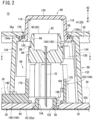
- the biasing member 114 is a spring member including a coil spring. As illustrated in Fig. 2 , the biasing member 114 is disposed between the inside of the pressing portion 118 of the pusher 86 and the receiving portion 98 of the needle hub 90. A biasing force of the biasing member 114 is applied to the needle hub 90 and the pusher 86. The biasing member 114 biases the needle member 82 toward the skin S of the patient. As the needle member 82 is biased toward the skin S of the patient by the biasing member 114, the needle member 82 can move in the puncture direction (arrow A1 direction) relative to the housing 14.
- the pair of first inclined portions 112 is disposed in the flange portion 120 of the pusher 86.
- the first inclined portions 112 protrude from the flange portion 120 toward the bottom wall 32 of the housing main body 26.
- the pair of first inclined portions 112 is disposed symmetrically with respect to the axial center of the pusher 86.
- the respective first inclined portions 112 are inclined with respect to the axial direction of the pusher 86.
- the first inclined portions 112 are inclined with respect to the puncture direction (arrow A1 direction) of the puncture needle 22.
- the first inclined portions 112 are inclined so as to extend clockwise in the puncture direction (arrow A1 direction).
- the pair of second inclined portions 116 is disposed on the respective guided portions 102a and 102b of the needle hub 90.
- the second inclined portions 116 are disposed at proximal ends of the guided portions 102a and 102b (refer to Fig. 6 ).
- the first inclined portions 112 of the pusher 86 can abut on the second inclined portions 116.
- the second inclined portions 116 are inclined with respect to the puncture direction (arrow A1 direction) of the needle member 82. That is, the second inclined portions 116 are inclined so as to extend clockwise in the distal direction (arrow A1 direction) when the needle member 82 is viewed from the proximal end in the distal direction.
- the second inclined portions 116 are inclined in the same direction as the first inclined portions 112.
- the guide member 88 can guide the pusher 86 along the axial direction when the puncture of the skin S is performed by the puncture needle 22.
- the guide member 88 is housed in the housing 14 (refer to Fig. 3 ).
- the guide member 88 is fixed to the housing main body 26 and is erected from the bottom wall 32 toward the housing cover 28.
- the guide member 88 partially surrounds the pusher 86 and the needle member 82.
- the guide member 88 has a guide main body 132 having a tubular shape, a pair of pusher guides 134, a pair of elastically deformable portions 136, and a lock portion 138.
- the guide main body 132 is disposed so as to surround the first hole portion 38 and abuts on the mounting surface 32b of the bottom wall 32 of the housing main body 26.
- One end (end on a side closer to the bottom wall 32) of the guide main body 132 faces the mounting surface 32b of the housing main body 26.
- the one end of the guide main body 132 has a second opening 140.
- the second opening 140 is opened by cutting out a part of an outer peripheral surface of the guide main body 132.
- the second opening 140 is formed in a rectangular shape along the outer peripheral surface of the guide main body 132.
- the second opening 140 faces the first opening 48 of the housing main body 26 (refer to Fig. 3 ).
- the first opening 48 and the second opening 140 have substantially the same size.
- the inside of the housing 14 and the inside of the guide member 88 communicate with the outside of the housing 14 through the first and second openings 48 and 140.
- the second opening 140 is opened toward the mounting surface 32b of the housing 14.
- the pair of pusher guides 134 can guide the pusher 86 along the puncture direction.
- the pair of pusher guides 134 protrudes from the guide main body 132 toward the housing cover 28.
- the pair of pusher guides 134 is disposed symmetrically with respect to an axial center of the guide member 88 (refer to Fig. 3 ).
- An end of the pusher guide 134 has a guide surface 134a.
- the guide surface 134a is disposed on the inner periphery of the end of the pusher guide 134 and faces the outer peripheral surface of the pressing portion 118 of the pusher 86.
- the guide surface 134a has an arcuate cross section corresponding to the outer peripheral surface of the pressing portion 118 (refer to Fig. 3 ). There is a gap between the guide surface 134a and the outer peripheral surface of the pusher 86. When the pusher 86 moves along the axial direction, the outer peripheral surface of the pusher 86 is guided along the axial direction (arrow A1 and A2 directions) by the guide surface 134a of the pusher guide 134.
- the inner surface of the housing cover 28 abuts on the ends of the pair of pusher guides 134.
- the housing cover 28 is held by the pusher guides 134.
- the pair of elastically deformable portions 136 extends along the axial direction of the guide main body 132.
- the elastically deformable portions 136 protrude from the guide main body 132 toward the upper wall 28a of the housing cover 28. Ends (root portions) of the elastically deformable portions 136 on the A1 side are fixed ends supported by the guide main body 132. Ends of the elastically deformable portions 136 on the A2 side are free ends.
- the elastically deformable portions 136 are elastically deformable in the radial direction with the root portions of the elastically deformable portions 136 as fulcrums. As illustrated in Fig.
- the pair of elastically deformable portions 136 is disposed symmetrically with respect to the axial center of the guide member 88.
- the elastically deformable portions 136 and the pusher guides 134 are spaced apart from each other in a circumferential direction of the guide member 88.
- the pair of lock portions 138 is disposed at the free ends of the pair of elastically deformable portions 136.
- the lock portions 138 protrude radially inward from the free ends of the elastically deformable portions 136, respectively.
- the lock portions 138 face the outer peripheral surface of the pusher 86 and face the pusher-side engagement portions 128 of the protruding portions 122, respectively.
- each of the lock portion 138 protrude from the free ends of the elastically deformable portions 136 toward the outer peripheral surface of the pusher 86.
- Each of the lock portion 138 has an inclined surface 142 facing the pusher 86.
- the inclined surface 142 is inclined radially inward in the puncture direction.
- radially inner ends of the lock portions 138 toward the pusher 86 are disposed radially inward of radially outer ends of the pusher-side engagement portions 128, respectively.
- the pusher-side engagement portions 128 are disposed on the housing cover 28 side with respect to the lock portions 138, respectively.
- the adjustment mechanism 24 is disposed at the distal portion of the housing 14.
- the adjustment mechanism 24 includes an adjustment member 144 rotatable along the bottom wall 32 of the housing main body 26. That is, the adjustment member 144 is disposed to be movable in a direction orthogonal to the puncture direction (arrow A1 direction) of the needle member 82 with respect to the housing 14.
- the adjustment member 144 is disposed on the mounting surface 32b of the bottom wall 32 of the housing main body 26.
- the adjustment member 144 is rotatable along the mounting surface 32b perpendicular to the puncture direction (arrow A1 direction) of the puncture needle 22.
- the adjustment member 144 has a main body portion 146 having a disk shape, an operation portion 148, and a movement preventing portion 150.
- An insertion hole 152 through which the puncture needle 22 of the needle member 82 can be inserted is provided at the center of the main body portion 146.
- the main body portion 146 faces the mounting surface 32b of the housing main body 26.
- the main body portion 146 has a plurality of fixing portions 154 protruding toward the bottom wall 32 of the housing 14 (refer to Fig. 2 ).
- the operation portion 148 moves along the mounting surface 32b of the housing main body 26 and the attachment portion 44.
- the operation portion 148 rotates in a substantially arc shape along the mounting surface 32b of the attachment portion 44 around the axis of the main body portion 146 (first hole portion 38) as a rotation center.
- the operation end 156 is disposed at an end of the operation portion 148 that is farthest radially outward from the main body portion 146.
- the operation end 156 is disposed at the outer edge portion of the attachment portion 44.
- the operation end 156 has a plurality of grooves 160 extending along the axial direction of the main body portion 146 and recessed radially inward.
- the grooves 160 are arranged in parallel along a moving direction of the operation portion 148.
- the operation portion 148 has a substantially fan shape gradually expanding from the main body portion 146 toward the operation end 156.
- the operation portion 148 is inserted into each of the first opening 48 of the housing main body 26 and the second opening 140 of the guide member 88.
- the operation end 156 of the operation portion 148 is exposed to the outside of the housing 14 through the first opening 48.
- the opposing surface 158 of the operation portion 148 has a protrusion 162.
- the protrusion 162 protrudes from the opposing surface 158 toward the housing main body 26 and extends along an extending direction of the operation portion 148 (refer to Fig. 5 ).
- the protrusion 162 is inserted into and engaged with any one of the first to third positioning grooves 46a, 46b, and 46c.
- a cross-sectional shape of the protrusion 162 viewed from the extending direction of the operation portion 148 is a semicircular shape.
- the shape of the protrusion 162 corresponds to the shape of the first to third positioning grooves 46a, 46b, and 46c.
- the user moves the adjustment member 144 along the attachment portion 44 by the operation end 156 of the operation portion 148, whereby the adjustment member 144 can be rotated along the mounting surface 32b around the main body portion 146.
- the protrusion 162 of the operation portion 148 is engaged with any one of the first to third positioning grooves 46a, 46b, and 46c, whereby the operation portion 148 in the attachment portion 44 is prevented from moving and is positioned at a predetermined position. That is, the rotation of the adjustment member 144 along the mounting surface 32b is restricted.
- the movement preventing portion 150 prevents the movement of the needle member 82 in the puncture direction (arrow A1 direction) by the abutment with the abutting portions 104a and 104b of the needle member 82.
- the movement preventing portion 150 extends from an outer edge portion of the main body portion 146 along the axial direction of the main body portion 146.
- a pair of the movement preventing portions 150 is disposed symmetrically with respect to the center of the main body portion 146 (refer to Fig. 10 ).
- Each of the movement preventing portions 150 has a plurality of adjustment step portions 164.
- the plurality of adjustment step portions 164 In the state before the skin S is punctured by the puncture needle 22, the plurality of adjustment step portions 164 have different spacing distances from the abutting portions 104a and 104b of the needle member 82 in the puncture direction.
- the movement preventing portion 150 includes three first to third adjustment step portions 166, 168, and 170 will be described.
- the first to third adjustment step portions 166, 168, and 170 are disposed on the outer edge portion of the main body portion 146.
- the first to third adjustment step portions 166, 168, and 170 are arranged in parallel in a circumferential direction of the main body portion 146.
- the first adjustment step portion 166, the second adjustment step portion 168, and the third adjustment step portion 170 are disposed clockwise in this order.
- a pair of the first adjustment step portions 166 is disposed symmetrically with respect to the axial center of the main body portion 146.
- Each of the first adjustment step portions 166 has a first abutted portion 166a on which the abutting portions 104a and 104b of the needle hub 90 can abut.
- the first abutted portion 166a extends in a direction orthogonal to the axial direction of the main body portion 146.
- the needle hub 90 moves in the puncture direction (arrow A1 direction) at the time of puncturing the skin S with the puncture needle 22, the first abutted portions 166a and the abutting surfaces 108 of the abutting portions 104a and 104b can abut on each other.
- the first abutted portions 166a of the pair of first adjustment step portions 166 and the abutting portions 104a and 104b of the needle member 82 are spaced apart from each other by a first distance L1 in the puncture direction.
- the first abutted portion 166a has a first-step-portion-side engagement portion 166b.
- the first-step-portion-side engagement portion 166b is recessed in the axial direction of the hub main body 92 from an end surface of the first abutted portion 166a.
- the first-step-portion-side engagement portion 166b is recessed in the puncture direction (arrow A1 direction) of the needle member 82.
- the first-step-portion-side engagement portion 166b gradually tapers in the puncture direction.
- the abutting portions 104a and 104b of the needle hub 90 face the first adjustment step portions 166, respectively, at a first adjustment position P1 (refer to Fig. 5 ).
- the needle hub 90 moves in the puncture direction at the first adjustment position P1
- the abutting surfaces 108 of the abutting portions 104a and 104b abut on the first abutted portions 166a, respectively.
- the hub-side engagement portions 110 are engaged with the first-step-portion-side engagement portions 166b, respectively.
- the puncture depth of the puncture needle 22 with respect to the skin S becomes a first puncture depth D1.
- the puncture depth refers to a depth from the skin S of the patient to the distal end of the puncture needle 22 punctured subcutaneously.
- the first puncture depth D1 is, for example, 12 mm.
- a pair of the second adjustment step portions 168 is disposed symmetrically with respect to the axial center of the main body portion 146.
- the second adjustment step portions 168 are adjacent to the first adjustment step portions 166, respectively, clockwise in the circumferential direction of the main body portion 146.
- the second adjustment step portion 168 is connected to a circumferential side portion of the first adjustment step portion 166.
- the second adjustment step portions 168 have second abutted portions 168a which can abut on the abutting portions 104a and 104b, respectively, of the needle hub 90.
- the second abutted portion 168a extends in a direction orthogonal to the axial direction of the main body portion 146.
- the second abutted portions 168a of the pair of second adjustment step portions 168 and the abutting portions 104a and 104b of the needle member 82 are spaced apart from each other by a second distance L2 in the puncture direction.
- the second distance L2 is smaller than the first distance L1 (L2 ⁇ L1). That is, the second adjustment step portions 168 are disposed closer to the abutting portions 104a and 104b of the needle member 82 than the first adjustment step portions 166.
- a protruding height of the second adjustment step portion 168 with respect to the main body portion 146 is larger than a protruding height of the first adjustment step portion 166 with respect to the main body portion 146.
- the second abutted portion 168a has a second-step-portion-side engagement portion 168b.
- the second-step-portion-side engagement portion 168b is recessed in the axial direction of the hub main body 92 from an end surface of the second abutted portion 168a.
- the second-step-portion-side engagement portion 168b is recessed in the puncture direction (arrow A1 direction) of the needle member 82.
- the second-step-portion-side engagement portion 168b gradually tapers in the puncture direction.
- the abutting portions 104a and 104b of the needle hub 90 face the second adjustment step portions 168, respectively, at a second adjustment position P2.
- the needle hub 90 moves in the puncture direction at the second adjustment position P2
- the abutting surfaces 108 of the abutting portions 104a and 104b abut on the second abutted portions 168a, respectively.
- the puncture depth of the puncture needle 22 with respect to the skin S becomes a second puncture depth D2.
- the second puncture depth D2 is smaller than the first puncture depth D1, and is, for example, 9 mm.
- the hub-side engagement portions 110 are engaged with the second-step-portion-side engagement portions 168b, respectively. That is, when the second adjustment position P2 is selected by the adjustment mechanism 24, the puncture depth becomes shallower than the first puncture depth D1 at the first adjustment position P1.
- a pair of the third adjustment step portions 170 is disposed symmetrically with respect to the axial center of the main body portion 146.
- the third adjustment step portion 170 on one side is disposed so as to face the operation portion 148.
- the third adjustment step portions 170 are adjacent to the second adjustment step portions 168, respectively, clockwise in the circumferential direction of the main body portion 146.
- the third adjustment step portion 170 is connected to a circumferential side portion of the second adjustment step portion 168.
- the third adjustment step portions 170 have third abutted portions 170a facing the abutting portions 104a and 104b, respectively, of the needle hub 90.
- the third abutted portion 170a extends in a direction orthogonal to the axial direction of the main body portion 146.
- the needle hub 90 moves in the puncture direction at the time of puncturing the skin S with the puncture needle 22
- the third abutted portions 170a and the abutting surfaces 108 of the abutting portions 104a and 104b can abut on each other.
- the third abutted portions 170a of the pair of third adjustment step portions 170 and the abutting portions 104a and 104b of the needle member 82 are spaced apart from each other by a third distance L3 in the puncture direction.
- the third distance L3 is smaller than the second distance L2 (L3 ⁇ L2 ⁇ L1). That is, the third adjustment step portions 170 are disposed closer to the abutting portions 104a and 104b of the needle member 82 than the second adjustment step portions 168.
- a protruding height of the third adjustment step portion 170 with respect to the main body portion 146 is larger than the protruding height of the second adjustment step portion 168 with respect to the main body portion 146.
- the third abutted portion 170a has a third-step-portion-side engagement portion 170b.
- the third-step-portion-side engagement portion 170b is recessed in the axial direction of the hub main body 92 from an end surface of the third abutted portion 170a.
- the third-step-portion-side engagement portion 170b is recessed in the puncture direction (arrow A1 direction) of the needle member 82.
- the third-step-portion-side engagement portion 170b gradually tapers in the puncture direction.
- the abutting portions 104a and 104b of the needle hub 90 face the third adjustment step portions 170, respectively, at a third adjustment position P3.
- the needle hub 90 moves in the puncture direction at the third adjustment position P3
- the abutting surfaces 108 of the abutting portions 104a and 104b abut on the third abutted portions 170a, respectively.
- the puncture depth of the puncture needle 22 with respect to the skin S becomes a third puncture depth D3.
- the third puncture depth D3 is smaller than the second puncture depth D2, and is, for example, 6 mm.
- the puncture depth becomes shallower than the second puncture depth D2 at the second adjustment position P2.
- the first to third adjustment step portions 166, 168, and 170 are formed in a stepped shape in which the protruding height with respect to the main body portion 146 changes stepwise in a rotation direction of the adjustment member 144 which is the circumferential direction of the main body portion 146.
- the first adjustment step portion 166 is selected to obtain the deepest (largest) puncture depth (first puncture depth D1)
- the third adjustment step portion 170 is selected to obtain the shallowest (smallest) puncture depth (third puncture depth D3)
- the second adjustment step portion 168 is selected to obtain a puncture depth between the first puncture depth D1 and the third puncture depth D3.
- the puncture depth for example, an optimum puncture depth is appropriately selected according to the thickness of subcutaneous fat of the patient.
- the movement preventing portion 150 is not limited to the case of including the three first to third adjustment step portions 166, 168, and 170.
- the quantity is not limited as long as two or more adjustment step portions 164 are provided.
- the user performs adjustment to the first adjustment position P1 by the adjustment member 144 of the adjustment mechanism 24 in order to perform the puncture at the first puncture depth D1.
- the user slides the operation end 156 of the operation portion 148 along the first opening 48 in a direction of approaching the first width-direction wall portion 36a with a finger.
- the operation end 156 has the plurality of grooves 160, slippage of the finger during the operation is prevented, and the operation portion 148 can be reliably moved along the first opening 48.
- the adjustment member 144 rotates around the main body portion 146 along the mounting surface 32b of the housing main body 26. At this time, as viewed along the puncture direction of the needle member 82 illustrated in Fig. 3 , the rotation direction of the adjustment member 144 is clockwise.
- the protrusion 162 of the operation portion 148 is engaged with the first positioning groove 46a, the first adjustment position P1 at which the abutting portions 104a and 104b of the needle hub 90 and the first adjustment step portions 166 can abut on each other at the time of puncture is obtained (refer to Fig. 6 ).
- the abutting portions 104a and 104b partially face the first adjustment step portions 166, respectively, in the axial direction of the needle hub 90.
- the abutting portions 104a and 104b of the needle hub 90 are spaced apart from the first adjustment step portions 166 of the adjustment mechanism 24 in the axial direction, and the abutting portions 104a and 104b of the needle hub 90 and the first adjustment step portions 166 are disposed to be offset in the circumferential direction.
- the contact surface 32a of the housing 14 is brought into contact with the skin S of the patient (the bonding material 42 is attached to the skin S).
- the user pushes the pressing portion 118 (pressing surface 124) of the pusher 86 in the puncture direction (arrow A1 direction), and pushes the pressing portion 118 into the housing 14 through the second hole portion 56.
- the pusher 86 moves in the puncture direction (arrow A1 direction) along the pusher guides 134.
- the biasing member 114 is compressed in the axial direction toward the needle hub 90 by the movement of the pusher 86 in the puncture direction.
- the pusher-side engagement portion 128 presses the inclined surfaces 142 of the pair of lock portions 138 in the puncture direction, and the elastically deformable portions 136 having the lock portions 138 are biased radially outward by the contact with the pusher-side engagement portion 128.
- the pusher-side engagement portion 128 passes the lock portions 138 and is disposed in the puncture direction with respect to the lock portions 138.
- the pusher guides 134 moves between the pair of guide pieces 130, whereby the rotation of the pusher 86 with respect to the pusher guides 134 is prevented. As a result, the pusher 86 moves along the puncture direction.
- the lock portion 138 (the elastically deformable portions 136) are not pressed radially outward any longer, so that the elastically deformable portions 136 return radially inward by elasticity.
- the pressing portion 118 of the pusher 86 is biased in a direction to be spaced apart from the needle hub 90 (direction opposite to the puncture direction) by the biasing member 114, but the pusher 86 is held by the lock portions 138 due to the engagement between the pusher-side engagement portion 128 and the lock portions 138.
- the needle member 82 does not move from the initial state. That is, when the pusher 86 has moved by a predetermined distance in the puncture direction in a state where the needle member 82 does not move, the lock portions 138 can prevent the movement of the pusher 86 in the direction opposite to the puncture direction by engaging with the pusher-side engagement portion 128 of the pusher 86 (the protruding portion 122). As a result, the biasing force of the biasing member 114 in the puncture direction (arrow A1 direction) is stored.
- the first inclined portions 112 of the pusher 86 press the second inclined portions 116 of the needle hub 90 in the puncture direction.
- the guided portions 102a and 102b having the second inclined portions 116 are prevented from moving in the puncture direction as the locking surfaces 106 abut on the locking portions 54 of the guide columns 50a and 50b, respectively, of the housing 14.
- a position of the needle member 82 in the rotation direction with respect to the housing 14 in the initial state illustrated in Fig. 5 is referred to as a "first position".
- the pair of guided portions 102a and 102b receives a force counterclockwise when viewed in the puncture direction due to the inclination of the first inclined portions 112 and the second inclined portions 116 (refer to Fig. 5 ).
- the needle hub 90 does not move in the puncture direction and starts to rotate in the counterclockwise direction from the first position, around the axis of the needle hub 90.
- the locking surfaces 106 of the needle hub 90 move along the locking portions 54 of the guide columns 50a and 50b.
- the needle hub 90 rotates and reaches a second position where the pair of guided portions 102a and 102b face proximal ends of the guide grooves 52, respectively, and the locking surfaces 106 are separated from engagement surfaces
- the needle hub 90 moves in the puncture direction (arrow A1 direction) by the biasing force of the biasing member 114.
- the guided portions 102a and 102b are inserted into the guide grooves 52, and the guided portions 102a and 102b are guided in the puncture direction along the guide grooves 52, respectively, whereby the needle hub 90 moves.
- the abutting portions 104a and 104b of the needle hub 90 face the first adjustment step portions 166 of the adjustment member 144, respectively, in the puncture direction.
- the needle hub 90 moves in the puncture direction, and the puncture needle 22 protrudes from the contact surface 32a toward the skin S through the second hole portion 56.
- the puncture needle 22 punctures the skin S of the patient.
- the tube 100 is elastically deformed.
- the abutting portions 104a and 104b of the needle member 82 abut on the first abutted portion 166a of the first adjustment step portion 166, so that further movement of the needle member 82 in the puncture direction is prevented.
- the puncture depth by the puncture needle 22 becomes the first puncture depth D1 by the contact between the abutting portions 104a and 104b and the first adjustment step portions 166.
- the hub-side engagement portions 110 of the abutting portions 104a and 104b are engaged with the first-step-portion-side engagement portions 166b of the first adjustment step portions 166, respectively, whereby the relative rotation between the needle member 82 and the adjustment member 144 is prevented.
- the abutment state between the abutting portions 104a and 104b of the needle member 82 and the first adjustment step portions 166 is suitably maintained.
- the engagement between the hub-side engagement portions 110 and the first-step-portion-side engagement portions 166b prevents the adjustment member 144 from rotating with respect to the needle member 82 and prevents the abutting portions 104a and 104b from moving to other adjustment step portions to change the puncture depth.
- the user operates the operation portion 148 to move the operation portion 148 to the second adjustment position P2 in the liquid medicine administration device 12 before use (in the initial state).
- the operation of the operation portion 148 makes the adjustment member 144 rotate counterclockwise along the attachment portion 44.
- the protrusion 162 of the operation portion 148 is engaged with the second positioning groove 46b and is positioned.
- the second adjustment step portions 168 are disposed at positions capable of abutting on the abutting portions 104a and 104b of the needle member 82.
- the user operates the operation portion 148 to move the operation portion 148 to the third adjustment position P3 in the liquid medicine administration device 12 before use (in the initial state).
- the operation of the operation portion 148 makes the adjustment member 144 rotate counterclockwise along the attachment portion 44.
- the protrusion 162 of the operation portion 148 is engaged with the third positioning groove 46c and is positioned.
- the third adjustment step portions 170 are disposed at positions capable of abutting on the abutting portions 104a and 104b of the needle member 82.
- the abutting portions 104a and 104b of the needle member 82 abut on the third abutted portions 170a of the third adjustment step portions 170 and are locked.
- the movement amount of the needle member 82 in the puncture direction is controlled, and the puncture needle 22 punctures the skin S at the third puncture depth D3.
- the puncture needle 22 moves toward the skin S to puncture the skin S by the puncture needle 22, it is possible to control the movement amount of the needle member 82 in the puncture direction and adjust the puncture depth of the puncture needle 22 with respect to the skin S by adjusting positions of the first to third adjustment step portions 166, 168, and 170 with respect to the housing 14 and making each of the abutting portions 104a and 104b of the needle hub 90 abut on one of the first to third adjustment step portions 166, 168, and 170.
- the adjustment mechanism 24 capable of adjusting the puncture depth of the skin S by the puncture needle 22 is provided, and the user operates the adjustment mechanism 24 to set the positions of the first to third adjustment step portions 166, 168, and 170 with respect to the housing 14 before puncturing the skin S with the puncture needle 22, so that each of the abutting portions 104a and 104b of the needle member 82 can abut on one adjustment step portion of the first to third adjustment step portions 166, 168, and 170 according to the positions of the first to third adjustment step portions 166, 168, and 170 with respect to the housing 14, and the puncture depth of the puncture needle 22 with respect to the skin S can be adjusted.
- the adjustment mechanism 24 can easily select the puncture depth of the puncture needle 22 with respect to the skin S of a living body and perform the puncture of the skin S at a desired depth.
- any one of the plurality of first to third adjustment step portions 166, 168, and 170 and each of the abutting portions 104a and 104b of the needle member 82 can be disposed to face each other by moving the adjustment mechanism 24 along the bottom wall 32 before puncturing the skin S with the puncture needle 22.
- any one of the plurality of first to third adjustment step portions 166, 168, and 170 and each of the abutting portions 104a and 104b of the needle member 82 can be disposed at positions facing each other by rotating the adjustment mechanism 24 before puncturing the skin S with the puncture needle 22.
- the needle hub 90 having the puncture needle 22 and the first to third adjustment step portions 166, 168, and 170 of the adjustment mechanism 24 can be coaxially disposed.
- each of the abutting portions 104a and 104b of the needle hub 90 can reliably abut on one of the first to third adjustment step portions 166, 168, and 170 at the time of puncturing the skin S with the puncture needle 22.
- the adjustment mechanism 24 can be easily moved with respect to the housing 14, and any one of the first to third adjustment step portions 166, 168, and 170 can be disposed to face each of the abutting portions 104a and 104b of the needle member 82.
- any of the first to third-step-portion-side engagement portions 166b, 168b, and 170b and the hub-side engagement portion 110 are engaged, so that a position of the adjustment mechanism 24 is maintained and a desired puncture depth is suitably maintained. Therefore, among the first to third adjustment step portions 166, 168, and 170, other adjustment step portions that do not abut on the abutting portions 104a and 104b are prevented from erroneously abutting on the abutting portions 104a and 104b to change the puncture depth of the puncture needle 22.
- the puncture needle 22 of the needle member 82 can be caused to protrude from the contact surface 32a of the housing 14 by the biasing force of the biasing member 114, and the skin S can be reliably punctured by the puncture needle 22.
- the pusher 86 When the user pushes the pusher 86 toward the housing 14, the pusher 86 is guided in the puncture direction by the pusher guides 134, so that the pusher 86 can be stably moved in the puncture direction.
- the pusher 86 Since the pusher 86 is pushed in the puncture direction and the pusher-side engagement portion 128 of the pusher 86 is locked by the lock portions 138 of the guide member 88, the movement of the pusher 86 in the direction opposite to the puncture direction is effectively prevented, and the biasing force of the biasing member 114 for puncture can be effectively secured. As a result, the needle member 82 is biased in the puncture direction by the biasing force of the biasing member 114 so that reliable puncture can be performed.
Landscapes
- Health & Medical Sciences (AREA)
- Vascular Medicine (AREA)
- Engineering & Computer Science (AREA)
- Anesthesiology (AREA)
- Biomedical Technology (AREA)
- Heart & Thoracic Surgery (AREA)
- Hematology (AREA)
- Life Sciences & Earth Sciences (AREA)
- Animal Behavior & Ethology (AREA)
- General Health & Medical Sciences (AREA)
- Public Health (AREA)
- Veterinary Medicine (AREA)
- Dermatology (AREA)
- Infusion, Injection, And Reservoir Apparatuses (AREA)
Abstract
Description
- The present invention relates to a puncture device including a needle member that punctures skin of a living body and a liquid medicine administration device including the puncture device.
-
European Patent No. 3463523 discloses a puncture device that punctures skin of a user (patient) to be administered with a puncture needle. A puncture device includes a needle assembly including a needle, a drive mechanism, and a contact member. The drive mechanism includes a drive plate and a drive member movably screwed with the drive plate. When the drive member moves in an axial direction, the drive member linearly displaces the needle assembly via the contact member, and performs puncture of the skin by the needle of the needle assembly. - In general, when puncture is performed by the puncture device, it is necessary to change a puncture depth of the needle according to the skin thickness (subcutaneous fat) of the patient. In the puncture device of
European Patent No. 3463523 , it is necessary to control a movement amount of the drive member in the axial direction when the puncture depth of the needle with respect to the skin is changed. However, drive control of the drive member is complicated, and it is difficult to accurately manage the puncture depth by controlling the movement amount of the drive member. - An object of the present invention is to solve the above problems.
- (1) A first aspect of the present invention is a puncture device including: a housing having a contact surface that comes into contact with skin of a living body; a needle member that includes a puncture needle and is movable relative to the housing along an axis of the puncture needle, the puncture needle being capable of protruding from the contact surface toward the skin; and an adjustment mechanism that is displaceable with respect to the housing and adjusts a puncture depth of the puncture needle with respect to the skin, wherein the adjustment mechanism includes a movement preventing portion that abuts on an abutting portion of the needle member and prevents movement in a puncture direction when the puncture needle moves toward the skin to perform puncture of the skin, the movement preventing portion includes a plurality of adjustment step portions having different distances from the abutting portion of the needle member in the puncture direction in a state before the puncture of the skin by the puncture needle is performed, and the abutting portion abuts on one of the plurality of adjustment step portions according to a position of the adjustment mechanism with respect to the housing to adjust a depth of the puncture needle with respect to the skin when the puncture needle moves toward the skin to perform the puncture of the skin.
- According to this puncture device, a user operates the adjustment mechanism to set positions of the adjustment step portions with respect to the housing before puncturing the skin with the puncture needle, so that the abutting portion of the needle member can abut on one of the plurality of adjustment step portions according to the positions of the plurality of adjustment step portions with respect to the housing, and the puncture depth of the puncture needle with respect to the skin can be adjusted. Therefore, it is possible to easily select the puncture depth of the puncture needle with respect to the skin of the living body by the adjustment mechanism and to perform the puncture of the skin at a desired depth.
- (2) In the puncture device according to (1), the adjustment mechanism may be displaceable along a plane perpendicular to the axis with respect to the housing.
- With this configuration, any one of the plurality of adjustment step portions and the abutting portion of the needle member can be disposed to face each other when the puncture of the skin is performed by the puncture needle.
- (3) In the puncture device according to (1) or (2), the adjustment mechanism may be rotatable with respect to the housing.
- (4) In the puncture device according to any one of (1) to (3), the adjustment mechanism may be rotatable around the axis of the puncture needle with respect to the housing.
- With this configuration, the needle member having the puncture needle and the adjustment step portions of the adjustment mechanism can be coaxially disposed, so that the abutting portion of the needle member and the adjustment step portions (movement preventing portion) can reliably abut on each other at the time of puncturing the skin with the puncture needle.
- (5) In the puncture device according to any one of (1) to (4), the adjustment mechanism may include an operation portion that is movable along a direction in which the plurality of adjustment step portions are arranged in parallel and protrudes to the outside of the housing.
- With this configuration, when the user operates the operation portion, the adjustment member can be easily moved with respect to the housing to cause any one of the plurality of adjustment step portions to face the abutting portion of the needle member.
- (6) In the puncture device according to any one of (1) to (5), each of the plurality of adjustment step portions includes a step-portion-side engagement portion including a recess or a projection, and the abutting portion includes a hub-side engagement portion including a projection or a recess to be engaged with the recess or the projection of the step-portion-side engagement portion.
- With this configuration, when one adjustment step portion of the plurality of adjustment step portions and the abutting portion abut on each other, the step-portion-side engagement portion and the hub-side engagement portion are engaged, so that a position of the adjustment mechanism is maintained and a desired puncture depth is suitably maintained. Therefore, it is possible to prevent the puncture depth from changing due to erroneous abutment between another adjustment step portion of the plurality of adjustment step portions and the abutting portion.
- (7) The puncture device according to any one of (1) to (6) may include a biasing member that is provided in the housing and biases the needle member toward the skin.
- With this configuration, the skin can be reliably punctured by causing the puncture needle of the needle member to protrude from the contact surface of the housing by the biasing member.
- (8) In the puncture device according to (7), a puncture mechanism that causes the needle member to protrude toward the skin with respect to the contact surface of the housing may be included, the puncture mechanism may include a pusher that has a first inclined portion inclined with respect to the puncture direction of the puncture needle and is movable in the puncture direction with respect to the housing, the biasing member, and a second inclined portion that is provided in the needle member, is inclined with respect to the puncture direction, and abuts on the first inclined portion, the needle member may rotate from a first position to a second position around an axis along the puncture direction, via the first inclined portion and the second inclined portion, when the pusher moves in the puncture direction, and the needle member reaching the second position may move in the puncture direction by a biasing force of the biasing member.
- (9) The puncture device according to (8) may include a guide member having a pusher guide that guides the pusher along the puncture direction.
- With this configuration, the pusher can be stably moved in the puncture direction by the pusher guide when the user pushes the pusher toward the housing.
- (10) The puncture device according to (8) or (9) may include a lock portion that engages with the pusher and prevents the pusher from moving in a direction opposite to the puncture direction against the biasing force of the biasing member when the pusher has moved in the puncture direction by a predetermined distance in a range in which the needle member is not rotated.
- With this configuration, when the pusher is locked by the lock portion, a resilient force for puncture can be effectively secured in the biasing member, and reliable puncture can be performed.
- (11) In the puncture device according to (10), the guide member may include the lock portion.
- (12) A second aspect of the present invention is a liquid medicine administration device including: the puncture device according to any one of (1) to (11); and a prefilled syringe that is filled with a liquid medicine, is connected to the needle member of the puncture device, and delivers the liquid medicine to the puncture needle.
- According to the present invention, the user operates the adjustment mechanism to set positions of the adjustment step portions with respect to the housing before puncturing the skin with the puncture needle, so that the abutting portion of the needle member can abut on one of the plurality of adjustment step portions according to the positions of the plurality of adjustment step portions with respect to the housing, and the puncture depth of the puncture needle with respect to the skin can be adjusted. Therefore, it is possible to easily select the puncture depth of the puncture needle with respect to the skin of the living body by the adjustment mechanism and to perform the puncture of the skin at a desired depth.
-
-
Fig. 1 is a partially-omitted external perspective view of a liquid medicine administration device including a puncture device according to an embodiment of the present invention. -
Fig. 2 is a cross-sectional view illustrating the puncture device inFig. 1 . -
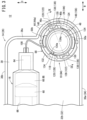
Fig. 3 is an enlarged plan view of the vicinity of the puncture device of the liquid medicine administration device inFig. 1 . -
Fig. 4 is an enlarged front view illustrating the vicinity of an operation portion of an adjustment mechanism inFig. 1 . -
Fig. 5 is a cross-sectional view taken along line V-V inFig. 2 . -
Fig. 6 is a partially-omitted side view of the puncture device in an initial state before puncture illustrated inFig. 2 . -
Fig. 7 is a side view of the puncture device before puncture inFig. 6 as viewed from another direction. -
Fig. 8 is a side view of the puncture device inFig. 6 illustrating a state in which a guide member is mounted. -
Fig. 9 is a cross-sectional view taken along line IX-IX inFig. 3 . -
Fig. 10 is an exploded perspective view of the puncture device. -
Fig. 11 is a partial cross-sectional side view of the puncture device inFig. 8 illustrating a state in which a pusher is pressed in a puncture direction. -
Fig. 12 is a cross-sectional view of the puncture device inFig. 9 illustrating a state in which skin is punctured by a puncture needle of a needle member. -
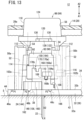
Fig. 13 is a partial cross-sectional side view illustrating a state in which the puncture needle is punctured at a second puncture depth. -
Fig. 14 is a partial cross-sectional side view illustrating a state in which the puncture needle is punctured at a third puncture depth. -
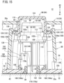
Fig. 15 is a cross-sectional view of the puncture device inFig. 11 illustrating a state in which the pusher is further pressed in the puncture direction. -
Fig. 16 is a cross-sectional view of the puncture device inFig. 15 illustrating a puncture state in which the needle member has moved in the puncture direction. -
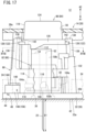
Fig. 17 is a side view of the puncture device at the time of puncture as viewed from another direction. -
Fig. 18 is a cross-sectional view taken along line XVIII-XVIII inFig. 17 . - As illustrated in
Fig. 1 , apuncture device 10 according to the present embodiment is used for a liquidmedicine administration device 12 that can administer a liquid medicine M. The liquidmedicine administration device 12 is used, for example, to be brought into contact with skin S (refer toFig. 2 ) of a patient and administer the liquid medicine M subcutaneously to the patient. - As illustrated in
Fig. 1 , the liquidmedicine administration device 12 includes ahousing 14, aprefilled syringe 16 that stores the liquid medicine M, amovement mechanism 18 that delivers the liquid medicine M in theprefilled syringe 16, thepuncture device 10 that can puncture the skin S (refer toFig. 9 ) of the patient, and anadjustment mechanism 24 that can adjust a puncture depth of a puncture needle 22 (refer toFig. 9 ) with respect to the skin S. - The
housing 14 serves as both of an enclosure of the liquidmedicine administration device 12 and an enclosure of thepuncture device 10. That is, the liquidmedicine administration device 12 and thepuncture device 10 share thehousing 14. - The
housing 14 includes a housingmain body 26 and ahousing cover 28. When the liquidmedicine administration device 12 including thepuncture device 10 administers the liquid medicine M, the housingmain body 26 is disposed on the skin S of the patient, and thehousing cover 28 is disposed on an opposite side to the skin S with the housingmain body 26 therebetween (refer toFig. 9 ). - As illustrated in
Fig. 2 , the housingmain body 26 and thehousing cover 28 overlap in a thickness direction (arrow A1 and A2 directions) of thehousing 14. The arrow A1 direction is a direction toward the skin S when the liquidmedicine administration device 12 is installed in the skin S of the patient. The arrow A2 direction is a direction away from the skin S when the liquidmedicine administration device 12 is installed in the skin S of the patient. Hereinafter, for convenience of description, a direction from thehousing cover 28 toward the housing main body 26 (arrow A1 direction) is referred to as downward, and a direction from the housingmain body 26 toward the housing cover 28 (arrow A2 direction) is referred to as upward. - The
housing cover 28 covers an upper portion of the housingmain body 26. The housingmain body 26 and thehousing cover 28 can be separated in a vertical direction (arrow A1 and A2 directions inFig. 1 ). - As illustrated in
Fig. 1 , thehousing 14 has aspace 30 surrounded by the housingmain body 26 and thehousing cover 28, and theprefilled syringe 16, themovement mechanism 18, and thepuncture device 10 are housed in thespace 30 of thehousing 14. - The housing
main body 26 has abottom wall 32 and aside wall 34 surrounding an outer edge of thebottom wall 32. Theside wall 34 is perpendicular to thebottom wall 32. Theside wall 34 includes a pair of first width-direction wall portions 36a and second width-direction wall portions 36b, adistal wall portion 36c, and aproximal wall portion 36d. The first width-direction wall portion 36a and the second width-direction wall portion 36b are disposed on both sides in a width direction (arrow C direction) orthogonal to a longitudinal direction (arrow B direction) of the housingmain body 26. The first width-direction wall portion 36a and the second width-direction wall portion 36b extend along the longitudinal direction (arrow B direction) of the housingmain body 26. Thedistal wall portion 36c is disposed at a distal portion of the housingmain body 26 and is orthogonal to the first width-direction wall portion 36a and the second width-direction wall portion 36b. Theproximal wall portion 36d is disposed at a proximal portion of the housingmain body 26 and is orthogonal to the first width-direction wall portion 36a and the second width-direction wall portion 36b. - As illustrated in
Fig. 2 , thebottom wall 32 of the housingmain body 26 has afirst hole portion 38. Thefirst hole portion 38 is disposed at the distal portion of the housingmain body 26 along the longitudinal direction (refer toFig. 5 ). Thefirst hole portion 38 passes through thebottom wall 32 and communicates the outside of the housingmain body 26 with thespace 30. - The
bottom wall 32 has acontact surface 32a that comes into contact with the skin S of the patient and a mountingsurface 32b on which theadjustment mechanism 24 is disposed. Thecontact surface 32a is disposed outside the housingmain body 26. In the present embodiment, thehousing 14 has abonding material 42 fixed to thebottom wall 32 of the housingmain body 26, and one surface of thebonding material 42 is the contact surface. Thecontact surface 32a is flat along the longitudinal direction (arrow B direction inFig. 1 ) of thehousing 14 and the width direction (arrow C direction inFig. 1 ) orthogonal to the longitudinal direction. The mountingsurface 32b is a surface that is disposed inside the housingmain body 26 and faces thespace 30. The mountingsurface 32b is a plane perpendicular to a puncture direction (arrow A1 direction) of thepuncture needle 22. - As illustrated in
Fig. 3 , thebottom wall 32 has anattachment portion 44 which is exposed to the outside and on which theadjustment mechanism 24 is disposed. Theattachment portion 44 is disposed in the vicinity of a corner portion between thedistal wall portion 36c and the first width-direction wall portion 36a of the housingmain body 26. Theattachment portion 44 bulges in a substantially semicircular shape from a distal wall of the housingmain body 26 toward the distal direction. The mountingsurface 32b of thebottom wall 32 is continuous to theattachment portion 44 in the same plane (refer toFig. 2 ). - As illustrated in
Fig. 4 , the mountingsurface 32b of theattachment portion 44 includes a plurality ofpositioning grooves 46. Each of thepositioning grooves 46 is recessed from the mountingsurface 32b toward thecontact surface 32a (arrow A1 direction). The number of thepositioning grooves 46 is set to correspond to the number of puncture depths of thepuncture needle 22 that can be adjusted by theadjustment mechanism 24. Hereinafter, a case where thepositioning grooves 46 include three first tothird positioning grooves - As illustrated in
Fig. 5 , the first tothird positioning grooves first hole portion 38 toward an outer edge portion of theattachment portion 44. The first tothird positioning grooves attachment portion 44. The first tothird positioning grooves first hole portion 38. The first tothird positioning grooves - The
first positioning groove 46a is disposed closest to the first width-direction wall portion 36a, and thefirst positioning groove 46a, thesecond positioning groove 46b, and thethird positioning groove 46c are disposed to be closer to thedistal wall portion 36c in this order (refer toFig. 5 ). - As illustrated in
Fig. 1 , awall portion 44a of theattachment portion 44 has afirst opening 48 facing the mountingsurface 32b. Thefirst opening 48 is opened in thewall portion 44a, passes through thewall portion 44a, and is formed in an elongated rectangular shape along the mountingsurface 32b (refer toFig. 4 ). Thefirst opening 48 faces the first tothird positioning grooves - As illustrated in
Fig. 6 , the housingmain body 26 includes a pair ofguide columns guide columns bottom wall 32 toward thehousing cover 28. The pair ofguide columns first hole portion 38 as the center (refer toFig. 5 ). That is, theguide columns first hole portion 38. - As illustrated in
Figs. 6 and7 , each of theguide columns guide groove 52 capable of guiding aneedle member 82 in an axial direction and a lockingportion 54 capable of guiding theneedle member 82 in a rotation direction. As illustrated inFig. 5 , theguide groove 52 is recessed radially outward from an inner surface facing an axis of thefirst hole portion 38. A cross-sectional shape of theguide groove 52 is a rectangular shape as viewed from an extending direction of each of theguide columns Fig. 5 . Theguide groove 52 extends along the extending direction of theguide columns Fig. 6 ). Theguide groove 52 of theguide column 50a on one side and theguide groove 52 of theguide column 50b on the other side face each other. - As illustrated in
Fig. 6 , the lockingportion 54 is adjacent to theguide groove 52 in the circumferential direction around thefirst hole portion 38. The lockingportion 54 is a flat surface orthogonal to the axial direction of each of theguide columns - An
upper wall 28a of thehousing cover 28 is formed in parallel with thebottom wall 32 of the housingmain body 26. Theupper wall 28a of thehousing cover 28 has asecond hole portion 56. Thesecond hole portion 56 is disposed at a distal portion of thehousing cover 28. Thefirst hole portion 38 and thesecond hole portion 56 face each other in the thickness direction of thehousing 14. - As illustrated in
Fig. 1 , theprefilled syringe 16 is housed in thehousing 14 and is disposed along the longitudinal direction (arrow B direction) of thehousing 14. Theprefilled syringe 16 includes abarrel 58, agasket 60, and arod 62. Thebarrel 58 has a cylindrical shape along an axial direction, of which a proximal end is opened. A distal end of thebarrel 58 has anozzle 64 that protrudes in the distal direction. Thegasket 60 is movably housed in thebarrel 58. Thegasket 60 is made of an elastic material and is liquid-tightly inserted into thebarrel 58. Amedicine chamber 66 filled with the liquid medicine M is provided between the distal end of thebarrel 58 and thegasket 60. - The
rod 62 is formed in a cylindrical shape. A distal portion of therod 62 is inserted into thebarrel 58 and is coupled to a proximal end of thegasket 60. A proximal portion of therod 62 is disposed outside thebarrel 58. Therod 62 is disposed to be movable in the axial direction (the distal direction, a proximal direction, and the arrow B direction) relative to thebarrel 58. - The
movement mechanism 18 includes amotor 68, agear portion 70, and ashaft 72. Themotor 68 is disposed in parallel with theprefilled syringe 16. Themotor 68 is electrically connected to apower supply unit 74. Thepower supply unit 74 is disposed in a distal direction of themotor 68. Thepower supply unit 74 can supply power to themotor 68. Thepower supply unit 74 is, for example, a battery. The power is supplied from thepower supply unit 74 to themotor 68, and the power rotationally drives a driving shaft (not illustrated) of themotor 68. Themotor 68 is driven and controlled by a controller (not illustrated). - The
gear portion 70 is disposed in a proximal direction of themotor 68. Thegear portion 70 includes adrive gear 76 coupled to the driving shaft, a drivengear 78 coupled to theshaft 72, and anintermediate gear 80 meshed with thedrive gear 76 and the drivengear 78. Theintermediate gear 80 is disposed between thedrive gear 76 and the drivengear 78. Thedrive gear 76, the drivengear 78, and theintermediate gear 80 are arranged in parallel in the width direction (arrow C direction) of thehousing 14. - By rotationally driving the
motor 68, thedrive gear 76 rotates together with the driving shaft (not illustrated) of themotor 68. As thedrive gear 76 rotates, theintermediate gear 80 and the drivengear 78 rotate so that theshaft 72 rotates. - The
shaft 72 extends along the axial direction and is inserted into therod 62. In therod 62, an outer peripheral surface of theshaft 72 is screwed with an inner peripheral surface of therod 62. Theshaft 72 is housed in thebarrel 58 of theprefilled syringe 16 together with therod 62. The drivengear 78 is coupled to a proximal end of theshaft 72. - When a driving force of the
motor 68 is transmitted to theshaft 72 via thegear portion 70 to rotate theshaft 72, therod 62 screwed with theshaft 72 moves along the axial direction (arrow B direction). The movement of therod 62 moves thegasket 60 in thebarrel 58 along the axial direction together with therod 62, and the liquid medicine M in themedicine chamber 66 is delivered in the distal direction by thegasket 60. - As illustrated in
Fig. 3 , thepuncture device 10 is disposed at a distal portion of thehousing 14. Thepuncture device 10 faces the first andsecond hole portions 38 and 56 (refer toFig. 2 ). As illustrated inFig. 8 , thepuncture device 10 includes theneedle member 82, apuncture mechanism 84 that biases theneedle member 82 toward the skin S of the patient (refer toFig. 9 ), and aguide member 88 that can guide apusher 86 of thepuncture mechanism 84 along the axial direction. - As illustrated in
Fig. 2 , theneedle member 82 includes thepuncture needle 22 and aneedle hub 90 that holds thepuncture needle 22. Thepuncture needle 22 is a hollow needle. A distal end of thepuncture needle 22 can puncture the skin S of the patient. A proximal end of thepuncture needle 22 is held at an axial center of theneedle hub 90. - The
needle hub 90 includes a hubmain body 92. The hubmain body 92 has a circular shape as viewed from an axial direction of the needle hub 90 (refer toFig. 5 ). The hubmain body 92 includes alarge diameter portion 94 and asmall diameter portion 96. Thelarge diameter portion 94 is disposed in the distal direction (arrow A1 direction) of the hubmain body 92. Thesmall diameter portion 96 is disposed in a proximal direction (arrow A2 direction) of thelarge diameter portion 94. A diameter of thesmall diameter portion 96 is smaller than a diameter of thelarge diameter portion 94. An annular receivingportion 98 extending in a radial direction is provided at a boundary between thesmall diameter portion 96 and thelarge diameter portion 94. - The
large diameter portion 94 of the hubmain body 92 includes a communication path (not illustrated). A distal end of the communication path communicates with the inside of thepuncture needle 22. Theprefilled syringe 16 and a proximal end of the communication path are connected by an elastically deformable tube 100 (refer toFig. 3 ). As illustrated inFig. 3 , thetube 100 is a tubular body and is disposed at the distal portion of thehousing 14. Thetube 100 has flexibility and can deliver the liquid medicine M from theprefilled syringe 16 to theneedle member 82. The liquid medicine M is supplied from theprefilled syringe 16 to the communication path of the needle member 82 (not illustrated) through thetube 100, and the liquid medicine M is delivered from the communication path to thepuncture needle 22. - As illustrated in
Fig. 5 , an outer peripheral surface of theneedle hub 90 has a pair of guidedportions portions portions main body 92. The guidedportion 102a on one side and the guidedportion 102b on the other side are symmetrically disposed with respect to an axial center of the hubmain body 92. As illustrated inFig. 6 , each of the guidedportions surface 106. The locking surfaces 106 are disposed at distal ends of the guidedportion surface 106 has a flat shape orthogonal to the axial direction of theneedle hub 90. - In an initial state before the skin S is punctured by the
puncture needle 22 illustrated inFig. 6 , the locking surfaces 106 of theneedle hub 90 abut on the lockingportions 54 of theguide columns needle hub 90 is prevented from moving in the puncture direction (the distal direction and the arrow A1 direction) with respect to thehousing 14 including theguide columns - The pair of abutting
portions main body 92. Each of the abuttingportions main body 92. The abuttingportion 104a on one side and the abuttingportion 104b on the other side are disposed symmetrically with respect to the axial center of the hubmain body 92. The abuttingportions portions main body 92. As illustrated inFig. 6 , each of the abuttingportions abutting surface 108 and a hub-side engagement portion 110 protruding from the abuttingsurface 108. The abuttingsurfaces 108 are disposed on end surfaces of the abuttingportions needle member 82. The abuttingsurfaces 108 are flat surfaces orthogonal to the axial direction of the hubmain body 92. - The hub-
side engagement portion 110 protrudes from the abuttingsurface 108 in the axial direction of the hubmain body 92. A protruding direction of the hub-side engagement portion 110 is the puncture direction (arrow A1 direction) of theneedle member 82. A distal end of the hub-side engagement portion 110 gradually tapers toward the distal end. - The
puncture mechanism 84 causes thepuncture needle 22 of theneedle member 82 to protrude from thecontact surface 32a of thehousing 14 in accordance with an operation of a user (for example, the patient or a medical personnel). Thepuncture mechanism 84 includes thepusher 86 in which a pair of firstinclined portions 112 is provided, a biasingmember 114, and a pair of secondinclined portions 116 provided on theneedle hub 90 and abutting on the firstinclined portions 112. - The
pusher 86 is disposed to be movable in the puncture direction (the axial direction and the arrow A1 direction) of thepuncture needle 22 with respect to thehousing 14. Thepusher 86 is disposed in the proximal direction (arrow A2 direction) of theneedle member 82. Before the skin S is punctured by thepuncture needle 22 illustrated inFig. 2 , a part of thesmall diameter portion 96 of theneedle hub 90 is inserted into thepusher 86. - As illustrated in
Fig. 9 , thepusher 86 includes apressing portion 118, aflange portion 120, and a pair of protrudingportions 122. Thepressing portion 118 has a bottomed cylindrical shape and is inserted into thesecond hole portion 56 of thehousing cover 28. Thepressing portion 118 is exposed to the outside of thehousing 14 through thesecond hole portion 56. A top of thepressing portion 118 has apressing surface 124 orthogonal to the axial direction of thepusher 86. When the skin S is punctured by thepuncture device 10, the user presses thepressing surface 124 of thepusher 86 toward the housing 14 (puncture direction). - The
flange portion 120 is disposed at an end of thepusher 86 on a side closer to theneedle hub 90. As illustrated inFig. 10 , theflange portion 120 is formed in an annular shape and is disposed at an outer edge portion of thepressing portion 118. Theflange portion 120 has a flange shape protruding radially outward from an outer peripheral surface of thepressing portion 118. As illustrated inFig. 9 , theflange portion 120 is disposed inside thehousing 14. Theflange portion 120 is disposed radially outward of thesecond hole portion 56. Theflange portion 120 faces an inner surface of thehousing cover 28. A diameter of theflange portion 120 is larger than a diameter of thesecond hole portion 56. - The
flange portion 120 has an annular groove adjacent to the outer peripheral surface of thepressing portion 118, and aseal ring 126 is attached to the annular groove. Theseal ring 126 is disposed to face the inner surface of thehousing cover 28 so as to be contactable with the inner surface. - As illustrated in
Fig. 3 , the pair of protrudingportions 122 protrudes radially outward from an outer peripheral surface of theflange portion 120. The protrudingportion 122 on one side and the protrudingportion 122 on the other side are disposed symmetrically with respect to an axial center of thepusher 86. Each of the protrudingportions 122 has a pusher-side engagement portion 128 and a pair ofguide pieces 130. The pair ofguide pieces 130 is disposed at both ends of the pusher-side engagement portion 128 in an extending direction, and further protrudes radially outward from the pusher-side engagement portion 128. The pusher-side engagement portion 128 is disposed between the pair ofguide pieces 130. - As illustrated in
Fig. 10 , the biasingmember 114 is a spring member including a coil spring. As illustrated inFig. 2 , the biasingmember 114 is disposed between the inside of thepressing portion 118 of thepusher 86 and the receivingportion 98 of theneedle hub 90. A biasing force of the biasingmember 114 is applied to theneedle hub 90 and thepusher 86. The biasingmember 114 biases theneedle member 82 toward the skin S of the patient. As theneedle member 82 is biased toward the skin S of the patient by the biasingmember 114, theneedle member 82 can move in the puncture direction (arrow A1 direction) relative to thehousing 14. - As illustrated in
Fig. 6 , the pair of firstinclined portions 112 is disposed in theflange portion 120 of thepusher 86. The firstinclined portions 112 protrude from theflange portion 120 toward thebottom wall 32 of the housingmain body 26. The pair of firstinclined portions 112 is disposed symmetrically with respect to the axial center of thepusher 86. The respective firstinclined portions 112 are inclined with respect to the axial direction of thepusher 86. In other words, the firstinclined portions 112 are inclined with respect to the puncture direction (arrow A1 direction) of thepuncture needle 22. When thepusher 86 is viewed in the puncture direction, the firstinclined portions 112 are inclined so as to extend clockwise in the puncture direction (arrow A1 direction). - As illustrated in
Fig. 5 , the pair of secondinclined portions 116 is disposed on the respective guidedportions needle hub 90. The secondinclined portions 116 are disposed at proximal ends of the guidedportions Fig. 6 ). The firstinclined portions 112 of thepusher 86 can abut on the secondinclined portions 116. The secondinclined portions 116 are inclined with respect to the puncture direction (arrow A1 direction) of theneedle member 82. That is, the secondinclined portions 116 are inclined so as to extend clockwise in the distal direction (arrow A1 direction) when theneedle member 82 is viewed from the proximal end in the distal direction. The secondinclined portions 116 are inclined in the same direction as the firstinclined portions 112. - As illustrated in
Fig. 8 , theguide member 88 can guide thepusher 86 along the axial direction when the puncture of the skin S is performed by thepuncture needle 22. Theguide member 88 is housed in the housing 14 (refer toFig. 3 ). Theguide member 88 is fixed to the housingmain body 26 and is erected from thebottom wall 32 toward thehousing cover 28. Theguide member 88 partially surrounds thepusher 86 and theneedle member 82. - The
guide member 88 has a guidemain body 132 having a tubular shape, a pair of pusher guides 134, a pair of elasticallydeformable portions 136, and alock portion 138. The guidemain body 132 is disposed so as to surround thefirst hole portion 38 and abuts on the mountingsurface 32b of thebottom wall 32 of the housingmain body 26. One end (end on a side closer to the bottom wall 32) of the guidemain body 132 faces the mountingsurface 32b of the housingmain body 26. - The one end of the guide
main body 132 has asecond opening 140. Thesecond opening 140 is opened by cutting out a part of an outer peripheral surface of the guidemain body 132. Thesecond opening 140 is formed in a rectangular shape along the outer peripheral surface of the guidemain body 132. Thesecond opening 140 faces thefirst opening 48 of the housing main body 26 (refer toFig. 3 ). Thefirst opening 48 and thesecond opening 140 have substantially the same size. The inside of thehousing 14 and the inside of theguide member 88 communicate with the outside of thehousing 14 through the first andsecond openings second opening 140 is opened toward the mountingsurface 32b of thehousing 14. - As illustrated in
Fig. 2 , the pair of pusher guides 134 can guide thepusher 86 along the puncture direction. The pair of pusher guides 134 protrudes from the guidemain body 132 toward thehousing cover 28. The pair of pusher guides 134 is disposed symmetrically with respect to an axial center of the guide member 88 (refer toFig. 3 ). An end of thepusher guide 134 has aguide surface 134a. - The
guide surface 134a is disposed on the inner periphery of the end of thepusher guide 134 and faces the outer peripheral surface of thepressing portion 118 of thepusher 86. Theguide surface 134a has an arcuate cross section corresponding to the outer peripheral surface of the pressing portion 118 (refer toFig. 3 ). There is a gap between theguide surface 134a and the outer peripheral surface of thepusher 86. When thepusher 86 moves along the axial direction, the outer peripheral surface of thepusher 86 is guided along the axial direction (arrow A1 and A2 directions) by theguide surface 134a of thepusher guide 134. - The inner surface of the
housing cover 28 abuts on the ends of the pair of pusher guides 134. Thehousing cover 28 is held by the pusher guides 134. - As illustrated in
Fig. 9 , the pair of elasticallydeformable portions 136 extends along the axial direction of the guidemain body 132. The elasticallydeformable portions 136 protrude from the guidemain body 132 toward theupper wall 28a of thehousing cover 28. Ends (root portions) of the elasticallydeformable portions 136 on the A1 side are fixed ends supported by the guidemain body 132. Ends of the elasticallydeformable portions 136 on the A2 side are free ends. The elasticallydeformable portions 136 are elastically deformable in the radial direction with the root portions of the elasticallydeformable portions 136 as fulcrums. As illustrated inFig. 3 , the pair of elasticallydeformable portions 136 is disposed symmetrically with respect to the axial center of theguide member 88. The elasticallydeformable portions 136 and the pusher guides 134 are spaced apart from each other in a circumferential direction of theguide member 88. - As illustrated in
Fig. 9 , the pair oflock portions 138 is disposed at the free ends of the pair of elasticallydeformable portions 136. Thelock portions 138 protrude radially inward from the free ends of the elasticallydeformable portions 136, respectively. When thepusher 86 is disposed inside theguide member 88, thelock portions 138 face the outer peripheral surface of thepusher 86 and face the pusher-side engagement portions 128 of the protrudingportions 122, respectively. - That is, the
respective lock portions 138 protrude from the free ends of the elasticallydeformable portions 136 toward the outer peripheral surface of thepusher 86. Each of thelock portion 138 has aninclined surface 142 facing thepusher 86. Theinclined surface 142 is inclined radially inward in the puncture direction. - In an initial state before puncture of the
puncture device 10 illustrated inFig. 9 , radially inner ends of thelock portions 138 toward thepusher 86 are disposed radially inward of radially outer ends of the pusher-side engagement portions 128, respectively. In the initial state of thepuncture device 10, the pusher-side engagement portions 128 are disposed on thehousing cover 28 side with respect to thelock portions 138, respectively. - When the
pusher 86 is pushed into thehousing 14 from the initial state illustrated inFig. 9 , thelock portions 138 are pressed radially outward by the pusher-side engagement portions 128, respectively, and the elasticallydeformable portions 136 are elastically deformed radially outward. After the pusher-side engagement portions 128 gets over thelock portions 138 as illustrated inFig. 11 , the pusher-side engagement portions 128 are locked by thelock portions 138, respectively. As a result, thepusher 86 having the pusher-side engagement portions 128 is prevented from moving toward the housing cover 28 (arrow A2 direction). In other words, thepusher 86 is prevented from moving in a direction opposite to the puncture direction of thepuncture needle 22 is prevented. - As illustrated in
Fig. 3 , theadjustment mechanism 24 is disposed at the distal portion of thehousing 14. Theadjustment mechanism 24 includes anadjustment member 144 rotatable along thebottom wall 32 of the housingmain body 26. That is, theadjustment member 144 is disposed to be movable in a direction orthogonal to the puncture direction (arrow A1 direction) of theneedle member 82 with respect to thehousing 14. - As illustrated in
Fig. 6 , theadjustment member 144 is disposed on the mountingsurface 32b of thebottom wall 32 of the housingmain body 26. Theadjustment member 144 is rotatable along the mountingsurface 32b perpendicular to the puncture direction (arrow A1 direction) of thepuncture needle 22. - As illustrated in
Fig. 10 , theadjustment member 144 has amain body portion 146 having a disk shape, anoperation portion 148, and amovement preventing portion 150. Aninsertion hole 152 through which thepuncture needle 22 of theneedle member 82 can be inserted is provided at the center of themain body portion 146. As illustrated inFig. 6 , themain body portion 146 faces the mountingsurface 32b of the housingmain body 26. Themain body portion 146 has a plurality of fixingportions 154 protruding toward thebottom wall 32 of the housing 14 (refer toFig. 2 ). - As illustrated in
Fig. 2 , the plurality of fixingportions 154 are disposed radially outward of theinsertion hole 152 around theinsertion hole 152. The plurality of fixingportions 154 are engaged with thefirst hole portion 38 of thebottom wall 32 of thehousing 14. As a result, theadjustment member 144 is rotatably supported with respect to the housingmain body 26 via themain body portion 146. Thefirst hole portion 38 of the housingmain body 26 and theinsertion hole 152 are coaxially disposed to face each other, and theadjustment member 144 is rotatably disposed around the axis of thepuncture needle 22 inserted into thefirst hole portion 38 and thefirst hole portion 38. - As illustrated in
Fig. 5 , theoperation portion 148 has anoperation end 156 that is touched and operated by the user when the puncture depth of thepuncture needle 22 is adjusted by theadjustment mechanism 24. Theoperation portion 148 protrudes radially outward from an outer peripheral surface of themain body portion 146 and extends by a predetermined length in a direction orthogonal to the axis of themain body portion 146. Theoperation portion 148 has a predetermined thickness in an axial direction of themain body portion 146. An opposingsurface 158 of theoperation portion 148 is a plane facing the mountingsurface 32b of the housingmain body 26 and the attachment portion 44 (refer toFig. 6 ). When theadjustment member 144 is rotated with respect to thehousing 14 by the operation of the user, theoperation portion 148 moves along the mountingsurface 32b of the housingmain body 26 and theattachment portion 44. Theoperation portion 148 rotates in a substantially arc shape along the mountingsurface 32b of theattachment portion 44 around the axis of the main body portion 146 (first hole portion 38) as a rotation center. - The
operation end 156 is disposed at an end of theoperation portion 148 that is farthest radially outward from themain body portion 146. Theoperation end 156 is disposed at the outer edge portion of theattachment portion 44. Theoperation end 156 has a plurality ofgrooves 160 extending along the axial direction of themain body portion 146 and recessed radially inward. Thegrooves 160 are arranged in parallel along a moving direction of theoperation portion 148. As viewed from the axial direction of themain body portion 146, theoperation portion 148 has a substantially fan shape gradually expanding from themain body portion 146 toward theoperation end 156. - As illustrated in
Fig. 3 , theoperation portion 148 is inserted into each of thefirst opening 48 of the housingmain body 26 and thesecond opening 140 of theguide member 88. Theoperation end 156 of theoperation portion 148 is exposed to the outside of thehousing 14 through thefirst opening 48. - As illustrated in
Fig. 4 , the opposingsurface 158 of theoperation portion 148 has aprotrusion 162. Theprotrusion 162 protrudes from the opposingsurface 158 toward the housingmain body 26 and extends along an extending direction of the operation portion 148 (refer toFig. 5 ). When the puncture depth of thepuncture needle 22 is selected by theadjustment mechanism 24, theprotrusion 162 is inserted into and engaged with any one of the first tothird positioning grooves protrusion 162 viewed from the extending direction of theoperation portion 148 is a semicircular shape. The shape of theprotrusion 162 corresponds to the shape of the first tothird positioning grooves - When adjusting the puncture depth of the skin S by the
puncture needle 22 by theadjustment mechanism 24, the user moves theadjustment member 144 along theattachment portion 44 by theoperation end 156 of theoperation portion 148, whereby theadjustment member 144 can be rotated along the mountingsurface 32b around themain body portion 146. At this time, theprotrusion 162 of theoperation portion 148 is engaged with any one of the first tothird positioning grooves operation portion 148 in theattachment portion 44 is prevented from moving and is positioned at a predetermined position. That is, the rotation of theadjustment member 144 along the mountingsurface 32b is restricted. - As illustrated in
Fig. 6 , when thepuncture needle 22 moves toward the skin S to puncture the skin S, themovement preventing portion 150 prevents the movement of theneedle member 82 in the puncture direction (arrow A1 direction) by the abutment with the abuttingportions needle member 82. Themovement preventing portion 150 extends from an outer edge portion of themain body portion 146 along the axial direction of themain body portion 146. A pair of themovement preventing portions 150 is disposed symmetrically with respect to the center of the main body portion 146 (refer toFig. 10 ). - Each of the
movement preventing portions 150 has a plurality ofadjustment step portions 164. In the state before the skin S is punctured by thepuncture needle 22, the plurality ofadjustment step portions 164 have different spacing distances from the abuttingportions needle member 82 in the puncture direction. Hereinafter, a case where themovement preventing portion 150 includes three first to thirdadjustment step portions - As illustrated in
Fig. 10 , the first to thirdadjustment step portions main body portion 146. The first to thirdadjustment step portions main body portion 146. Along the axial direction of themain body portion 146, when themain body portion 146 is viewed in the puncture direction, the firstadjustment step portion 166, the secondadjustment step portion 168, and the thirdadjustment step portion 170 are disposed clockwise in this order. - A pair of the first
adjustment step portions 166 is disposed symmetrically with respect to the axial center of themain body portion 146. Each of the firstadjustment step portions 166 has a first abuttedportion 166a on which the abuttingportions needle hub 90 can abut. The first abuttedportion 166a extends in a direction orthogonal to the axial direction of themain body portion 146. As illustrated inFig. 12 , when theneedle hub 90 moves in the puncture direction (arrow A1 direction) at the time of puncturing the skin S with thepuncture needle 22, the first abuttedportions 166a and the abuttingsurfaces 108 of the abuttingportions - As illustrated in
Fig. 9 , in the initial state before the skin S is punctured by thepuncture needle 22, the first abuttedportions 166a of the pair of firstadjustment step portions 166 and the abuttingportions needle member 82 are spaced apart from each other by a first distance L1 in the puncture direction. - As illustrated in
Fig. 6 , the first abuttedportion 166a has a first-step-portion-side engagement portion 166b. The first-step-portion-side engagement portion 166b is recessed in the axial direction of the hubmain body 92 from an end surface of the first abuttedportion 166a. The first-step-portion-side engagement portion 166b is recessed in the puncture direction (arrow A1 direction) of theneedle member 82. The first-step-portion-side engagement portion 166b gradually tapers in the puncture direction. - As illustrated in
Fig. 12 , when theadjustment member 144 is rotated by theoperation portion 148 and theprotrusion 162 of theoperation portion 148 is engaged with thefirst positioning groove 46a, the abuttingportions needle hub 90 face the firstadjustment step portions 166, respectively, at a first adjustment position P1 (refer toFig. 5 ). When theneedle hub 90 moves in the puncture direction at the first adjustment position P1, the abuttingsurfaces 108 of the abuttingportions portions 166a, respectively. The hub-side engagement portions 110 are engaged with the first-step-portion-side engagement portions 166b, respectively. At this time, the puncture depth of thepuncture needle 22 with respect to the skin S becomes a first puncture depth D1. Note that the puncture depth refers to a depth from the skin S of the patient to the distal end of thepuncture needle 22 punctured subcutaneously. The first puncture depth D1 is, for example, 12 mm. When the abuttingportions needle hub 90 abut on the first abuttedportions 166a, respectively, the hub-side engagement portions 110 are engaged with the first-step-portion-side engagement portions 166b, respectively. - As illustrated in
Fig. 10 , a pair of the secondadjustment step portions 168 is disposed symmetrically with respect to the axial center of themain body portion 146. When themovement preventing portion 150 is viewed in the puncture direction of theneedle member 82, the secondadjustment step portions 168 are adjacent to the firstadjustment step portions 166, respectively, clockwise in the circumferential direction of themain body portion 146. As illustrated inFig. 6 , the secondadjustment step portion 168 is connected to a circumferential side portion of the firstadjustment step portion 166. The secondadjustment step portions 168 have second abuttedportions 168a which can abut on the abuttingportions needle hub 90. The second abuttedportion 168a extends in a direction orthogonal to the axial direction of themain body portion 146. - As illustrated in
Fig. 6 , in the initial state before the skin S is punctured by thepuncture needle 22, the second abuttedportions 168a of the pair of secondadjustment step portions 168 and the abuttingportions needle member 82 are spaced apart from each other by a second distance L2 in the puncture direction. The second distance L2 is smaller than the first distance L1 (L2 < L1). That is, the secondadjustment step portions 168 are disposed closer to the abuttingportions needle member 82 than the firstadjustment step portions 166. In other words, a protruding height of the secondadjustment step portion 168 with respect to themain body portion 146 is larger than a protruding height of the firstadjustment step portion 166 with respect to themain body portion 146. - The second abutted
portion 168a has a second-step-portion-side engagement portion 168b. The second-step-portion-side engagement portion 168b is recessed in the axial direction of the hubmain body 92 from an end surface of the second abuttedportion 168a. The second-step-portion-side engagement portion 168b is recessed in the puncture direction (arrow A1 direction) of theneedle member 82. The second-step-portion-side engagement portion 168b gradually tapers in the puncture direction. - As illustrated in
Fig. 13 , when theadjustment member 144 is rotated by theoperation portion 148 and theprotrusion 162 of theoperation portion 148 is engaged with thesecond positioning groove 46b, the abuttingportions needle hub 90 face the secondadjustment step portions 168, respectively, at a second adjustment position P2. When theneedle hub 90 moves in the puncture direction at the second adjustment position P2, the abuttingsurfaces 108 of the abuttingportions portions 168a, respectively. At this time, the puncture depth of thepuncture needle 22 with respect to the skin S becomes a second puncture depth D2. The second puncture depth D2 is smaller than the first puncture depth D1, and is, for example, 9 mm. When the abuttingportions needle hub 90 abut on the second abuttedportions 168a, respectively, the hub-side engagement portions 110 are engaged with the second-step-portion-side engagement portions 168b, respectively. That is, when the second adjustment position P2 is selected by theadjustment mechanism 24, the puncture depth becomes shallower than the first puncture depth D1 at the first adjustment position P1. - As illustrated in
Fig. 10 , a pair of the thirdadjustment step portions 170 is disposed symmetrically with respect to the axial center of themain body portion 146. The thirdadjustment step portion 170 on one side is disposed so as to face theoperation portion 148. When themovement preventing portion 150 is viewed in the puncture direction of theneedle member 82, the thirdadjustment step portions 170 are adjacent to the secondadjustment step portions 168, respectively, clockwise in the circumferential direction of themain body portion 146. The thirdadjustment step portion 170 is connected to a circumferential side portion of the secondadjustment step portion 168. The thirdadjustment step portions 170 have third abuttedportions 170a facing the abuttingportions needle hub 90. The third abuttedportion 170a extends in a direction orthogonal to the axial direction of themain body portion 146. When theneedle hub 90 moves in the puncture direction at the time of puncturing the skin S with thepuncture needle 22, the third abuttedportions 170a and the abuttingsurfaces 108 of the abuttingportions - As illustrated in
Fig. 6 , in the initial state before the skin S is punctured by thepuncture needle 22, the third abuttedportions 170a of the pair of thirdadjustment step portions 170 and the abuttingportions needle member 82 are spaced apart from each other by a third distance L3 in the puncture direction. The third distance L3 is smaller than the second distance L2 (L3 < L2 < L1). That is, the thirdadjustment step portions 170 are disposed closer to the abuttingportions needle member 82 than the secondadjustment step portions 168. In other words, a protruding height of the thirdadjustment step portion 170 with respect to themain body portion 146 is larger than the protruding height of the secondadjustment step portion 168 with respect to themain body portion 146. - The third abutted
portion 170a has a third-step-portion-side engagement portion 170b. The third-step-portion-side engagement portion 170b is recessed in the axial direction of the hubmain body 92 from an end surface of the third abuttedportion 170a. The third-step-portion-side engagement portion 170b is recessed in the puncture direction (arrow A1 direction) of theneedle member 82. The third-step-portion-side engagement portion 170b gradually tapers in the puncture direction. - As illustrated in
Fig. 14 , when theadjustment member 144 is rotated by theoperation portion 148 and theprotrusion 162 of theoperation portion 148 is engaged with thethird positioning groove 46c, the abuttingportions needle hub 90 face the thirdadjustment step portions 170, respectively, at a third adjustment position P3. When theneedle hub 90 moves in the puncture direction at the third adjustment position P3, the abuttingsurfaces 108 of the abuttingportions portions 170a, respectively. At this time, the puncture depth of thepuncture needle 22 with respect to the skin S becomes a third puncture depth D3. The third puncture depth D3 is smaller than the second puncture depth D2, and is, for example, 6 mm. When the abuttingportions needle hub 90 abut on the third abuttedportions 170a, respectively, the hub-side engagement portions 110 are engaged with the third-step-portion-side engagement portions 170b, respectively. - That is, when the third adjustment position P3 is selected by the
adjustment mechanism 24, the puncture depth becomes shallower than the second puncture depth D2 at the second adjustment position P2. - The first to third
adjustment step portions main body portion 146 changes stepwise in a rotation direction of theadjustment member 144 which is the circumferential direction of themain body portion 146. In theadjustment mechanism 24, the firstadjustment step portion 166 is selected to obtain the deepest (largest) puncture depth (first puncture depth D1), the thirdadjustment step portion 170 is selected to obtain the shallowest (smallest) puncture depth (third puncture depth D3), and the secondadjustment step portion 168 is selected to obtain a puncture depth between the first puncture depth D1 and the third puncture depth D3. As the puncture depth, for example, an optimum puncture depth is appropriately selected according to the thickness of subcutaneous fat of the patient. - Note that the
movement preventing portion 150 is not limited to the case of including the three first to thirdadjustment step portions adjustment step portions 164 are provided. - Next, an operation of the liquid
medicine administration device 12 including thepuncture device 10 will be described. Hereinafter, a case where theadjustment mechanism 24 is set at the first adjustment position P1 and the skin S is punctured by thepuncture needle 22 at the first puncture depth D1 as illustrated inFig. 5 will be described. - First, in the liquid
medicine administration device 12 before use (in the initial state) before the puncture is performed as illustrated inFig. 6 , the user (user) performs adjustment to the first adjustment position P1 by theadjustment member 144 of theadjustment mechanism 24 in order to perform the puncture at the first puncture depth D1. The user slides theoperation end 156 of theoperation portion 148 along thefirst opening 48 in a direction of approaching the first width-direction wall portion 36a with a finger. At this time, since theoperation end 156 has the plurality ofgrooves 160, slippage of the finger during the operation is prevented, and theoperation portion 148 can be reliably moved along thefirst opening 48. - With the operation of the
operation portion 148, theadjustment member 144 rotates around themain body portion 146 along the mountingsurface 32b of the housingmain body 26. At this time, as viewed along the puncture direction of theneedle member 82 illustrated inFig. 3 , the rotation direction of theadjustment member 144 is clockwise. When theprotrusion 162 of theoperation portion 148 is engaged with thefirst positioning groove 46a, the first adjustment position P1 at which the abuttingportions needle hub 90 and the firstadjustment step portions 166 can abut on each other at the time of puncture is obtained (refer toFig. 6 ). The abuttingportions adjustment step portions 166, respectively, in the axial direction of theneedle hub 90. - At this time, in the liquid
medicine administration device 12 before use (in the initial state) illustrated inFig. 6 , the abuttingportions needle hub 90 are spaced apart from the firstadjustment step portions 166 of theadjustment mechanism 24 in the axial direction, and the abuttingportions needle hub 90 and the firstadjustment step portions 166 are disposed to be offset in the circumferential direction. - Next, the
contact surface 32a of thehousing 14 is brought into contact with the skin S of the patient (thebonding material 42 is attached to the skin S). As illustrated inFig. 11 , the user pushes the pressing portion 118 (pressing surface 124) of thepusher 86 in the puncture direction (arrow A1 direction), and pushes thepressing portion 118 into thehousing 14 through thesecond hole portion 56. As a result, thepusher 86 moves in the puncture direction (arrow A1 direction) along the pusher guides 134. At this time, the biasingmember 114 is compressed in the axial direction toward theneedle hub 90 by the movement of thepusher 86 in the puncture direction. - With the movement of the
pusher 86, the pusher-side engagement portion 128 presses theinclined surfaces 142 of the pair oflock portions 138 in the puncture direction, and the elasticallydeformable portions 136 having thelock portions 138 are biased radially outward by the contact with the pusher-side engagement portion 128. When the elasticallydeformable portions 136 are elastically deformed and the free ends of the elasticallydeformable portions 136 move radially outward so that thepusher 86 further moves in the puncture direction, the pusher-side engagement portion 128 passes thelock portions 138 and is disposed in the puncture direction with respect to thelock portions 138. At this time, the pusher guides 134 moves between the pair ofguide pieces 130, whereby the rotation of thepusher 86 with respect to the pusher guides 134 is prevented. As a result, thepusher 86 moves along the puncture direction. - After the pusher-
side engagement portion 128 passes thelock portions 138, the lock portion 138 (the elastically deformable portions 136) are not pressed radially outward any longer, so that the elasticallydeformable portions 136 return radially inward by elasticity. As a result, the pusher-side engagement portion 128 is engaged with thelock portions 138, and the movement of the pusher-side engagement portion 128 toward thelock portions 138 is prevented. Thepressing portion 118 of thepusher 86 is biased in a direction to be spaced apart from the needle hub 90 (direction opposite to the puncture direction) by the biasingmember 114, but thepusher 86 is held by thelock portions 138 due to the engagement between the pusher-side engagement portion 128 and thelock portions 138. - At this time, since the
pusher 86 and theneedle member 82 are not in contact with each other, theneedle member 82 does not move from the initial state. That is, when thepusher 86 has moved by a predetermined distance in the puncture direction in a state where theneedle member 82 does not move, thelock portions 138 can prevent the movement of thepusher 86 in the direction opposite to the puncture direction by engaging with the pusher-side engagement portion 128 of the pusher 86 (the protruding portion 122). As a result, the biasing force of the biasingmember 114 in the puncture direction (arrow A1 direction) is stored. - As illustrated in
Fig. 15 , when thepusher 86 is further pushed in the puncture direction, the firstinclined portions 112 of thepusher 86 press the secondinclined portions 116 of theneedle hub 90 in the puncture direction. At this time, as illustrated inFig. 5 , the guidedportions inclined portions 116 are prevented from moving in the puncture direction as the locking surfaces 106 abut on the lockingportions 54 of theguide columns housing 14. A position of theneedle member 82 in the rotation direction with respect to thehousing 14 in the initial state illustrated inFig. 5 is referred to as a "first position". - When the second
inclined portions 116 of theneedle hub 90 are pushed in the puncture direction (arrow A1 direction) by the firstinclined portions 112 of thepusher 86, the pair of guidedportions inclined portions 112 and the second inclined portions 116 (refer toFig. 5 ). As a result, theneedle hub 90 does not move in the puncture direction and starts to rotate in the counterclockwise direction from the first position, around the axis of theneedle hub 90. The locking surfaces 106 of theneedle hub 90 move along the lockingportions 54 of theguide columns - As illustrated in
Fig. 18 , when theneedle hub 90 rotates and reaches a second position where the pair of guidedportions guide grooves 52, respectively, and the locking surfaces 106 are separated from engagement surfaces, theneedle hub 90 moves in the puncture direction (arrow A1 direction) by the biasing force of the biasingmember 114. At this time, as illustrated inFig. 17 , the guidedportions guide grooves 52, and the guidedportions guide grooves 52, respectively, whereby theneedle hub 90 moves. At this time, the abuttingportions needle hub 90 face the firstadjustment step portions 166 of theadjustment member 144, respectively, in the puncture direction. - The
needle hub 90 moves in the puncture direction, and thepuncture needle 22 protrudes from thecontact surface 32a toward the skin S through thesecond hole portion 56. Thepuncture needle 22 punctures the skin S of the patient. As theneedle member 82 moves in the puncture direction, thetube 100 is elastically deformed. At this time, the abuttingportions needle member 82 abut on the first abuttedportion 166a of the firstadjustment step portion 166, so that further movement of theneedle member 82 in the puncture direction is prevented. The puncture depth by thepuncture needle 22 becomes the first puncture depth D1 by the contact between the abuttingportions adjustment step portions 166. - As illustrated in
Fig. 12 , the hub-side engagement portions 110 of the abuttingportions side engagement portions 166b of the firstadjustment step portions 166, respectively, whereby the relative rotation between theneedle member 82 and theadjustment member 144 is prevented. As a result, the abutment state between the abuttingportions needle member 82 and the firstadjustment step portions 166 is suitably maintained. The engagement between the hub-side engagement portions 110 and the first-step-portion-side engagement portions 166b prevents theadjustment member 144 from rotating with respect to theneedle member 82 and prevents the abuttingportions - After the puncture of the
puncture needle 22 to the skin S as illustrated inFig. 17 is completed, by turning on a power supply (not illustrated) of the liquidmedicine administration device 12, power is supplied from thepower supply unit 74 illustrated inFig. 1 to themotor 68, and themotor 68 is driven. As themotor 68 is driven, each of thedrive gear 76, theintermediate gear 80, and the drivengear 78 rotates, theshaft 72 rotates, so that therod 62 moves in the distal direction in thebarrel 58. When thegasket 60 is pushed in the distal direction by therod 62, the liquid medicine M in themedicine chamber 66 is delivered from thenozzle 64 to thetube 100. The liquid medicine M is supplied to the communication path of theneedle hub 90, and is subcutaneously administered to the patient through thepuncture needle 22. - As illustrated in
Fig. 13 , in a case where the puncture depth of thepuncture needle 22 is set to the second puncture depth D2 by theadjustment member 144, the user operates theoperation portion 148 to move theoperation portion 148 to the second adjustment position P2 in the liquidmedicine administration device 12 before use (in the initial state). The operation of theoperation portion 148 makes theadjustment member 144 rotate counterclockwise along theattachment portion 44. Theprotrusion 162 of theoperation portion 148 is engaged with thesecond positioning groove 46b and is positioned. The secondadjustment step portions 168 are disposed at positions capable of abutting on the abuttingportions needle member 82. When thepusher 86 is pushed and theneedle member 82 is moved in the puncture direction by the biasingmember 114, the abuttingportions needle member 82 abut on the second abuttedportions 168a of the secondadjustment step portions 168 and are locked. As a result, a movement amount of theneedle member 82 in the puncture direction is controlled, and thepuncture needle 22 punctures the skin S at the second puncture depth D2. - As illustrated in
Fig. 14 , in a case where the puncture depth of thepuncture needle 22 is set to the third puncture depth D3 by theadjustment member 144, the user operates theoperation portion 148 to move theoperation portion 148 to the third adjustment position P3 in the liquidmedicine administration device 12 before use (in the initial state). The operation of theoperation portion 148 makes theadjustment member 144 rotate counterclockwise along theattachment portion 44. Theprotrusion 162 of theoperation portion 148 is engaged with thethird positioning groove 46c and is positioned. The thirdadjustment step portions 170 are disposed at positions capable of abutting on the abuttingportions needle member 82. When thepusher 86 is pushed and theneedle member 82 is moved in the puncture direction by the biasingmember 114, the abuttingportions needle member 82 abut on the third abuttedportions 170a of the thirdadjustment step portions 170 and are locked. As a result, the movement amount of theneedle member 82 in the puncture direction is controlled, and thepuncture needle 22 punctures the skin S at the third puncture depth D3. - That is, when the
puncture needle 22 moves toward the skin S to puncture the skin S by thepuncture needle 22, it is possible to control the movement amount of theneedle member 82 in the puncture direction and adjust the puncture depth of thepuncture needle 22 with respect to the skin S by adjusting positions of the first to thirdadjustment step portions housing 14 and making each of the abuttingportions needle hub 90 abut on one of the first to thirdadjustment step portions - As described above, in the embodiment of the present invention, the
adjustment mechanism 24 capable of adjusting the puncture depth of the skin S by thepuncture needle 22 is provided, and the user operates theadjustment mechanism 24 to set the positions of the first to thirdadjustment step portions housing 14 before puncturing the skin S with thepuncture needle 22, so that each of the abuttingportions needle member 82 can abut on one adjustment step portion of the first to thirdadjustment step portions adjustment step portions housing 14, and the puncture depth of thepuncture needle 22 with respect to the skin S can be adjusted. As a result, theadjustment mechanism 24 can easily select the puncture depth of thepuncture needle 22 with respect to the skin S of a living body and perform the puncture of the skin S at a desired depth. - Since the
adjustment mechanism 24 is disposed so as to be displaceable along the bottom wall 32 (mountingsurface 32b) of the housingmain body 26 disposed perpendicular to the axis of thepuncture needle 22, when the puncture of the skin S is performed by thepuncture needle 22, any one of the plurality of first to thirdadjustment step portions portions needle member 82 can be disposed to face each other by moving theadjustment mechanism 24 along thebottom wall 32 before puncturing the skin S with thepuncture needle 22. - Since the
adjustment mechanism 24 is rotatably disposed with respect to the housingmain body 26, when the skin S is punctured by thepuncture needle 22, any one of the plurality of first to thirdadjustment step portions portions needle member 82 can be disposed at positions facing each other by rotating theadjustment mechanism 24 before puncturing the skin S with thepuncture needle 22. - Since the
adjustment mechanism 24 is disposed so as to be rotatable with respect to thehousing 14 around the axis of thepuncture needle 22, theneedle hub 90 having thepuncture needle 22 and the first to thirdadjustment step portions adjustment mechanism 24 can be coaxially disposed. As a result, each of the abuttingportions needle hub 90 can reliably abut on one of the first to thirdadjustment step portions puncture needle 22. - When the user operates the
operation portion 148 of theadjustment member 144, theadjustment mechanism 24 can be easily moved with respect to thehousing 14, and any one of the first to thirdadjustment step portions portions needle member 82. - When one of the first to third
adjustment step portions portions needle hub 90 abut on each other, any of the first to third-step-portion-side engagement portions side engagement portion 110 are engaged, so that a position of theadjustment mechanism 24 is maintained and a desired puncture depth is suitably maintained. Therefore, among the first to thirdadjustment step portions portions portions puncture needle 22. - Since the biasing
member 114 that biases theneedle member 82 in the puncture direction is provided, thepuncture needle 22 of theneedle member 82 can be caused to protrude from thecontact surface 32a of thehousing 14 by the biasing force of the biasingmember 114, and the skin S can be reliably punctured by thepuncture needle 22. - When the user pushes the
pusher 86 toward thehousing 14, thepusher 86 is guided in the puncture direction by the pusher guides 134, so that thepusher 86 can be stably moved in the puncture direction. - Since the
pusher 86 is pushed in the puncture direction and the pusher-side engagement portion 128 of thepusher 86 is locked by thelock portions 138 of theguide member 88, the movement of thepusher 86 in the direction opposite to the puncture direction is effectively prevented, and the biasing force of the biasingmember 114 for puncture can be effectively secured. As a result, theneedle member 82 is biased in the puncture direction by the biasing force of the biasingmember 114 so that reliable puncture can be performed. - Note that the present invention is not limited to the above disclosure, and various configurations can be adopted without departing from the gist of the present invention.
Claims (12)
- A puncture device comprising:a housing having a contact surface that comes into contact with skin of a living body;a needle member that comprises a puncture needle and is movable relative to the housing along an axis of the puncture needle, the puncture needle being capable of protruding from the contact surface toward the skin; andan adjustment mechanism that is displaceable with respect to the housing and adjusts a puncture depth of the puncture needle with respect to the skin,whereinthe adjustment mechanism comprises a movement preventing portion that abuts on an abutting portion of the needle member and prevents movement in a puncture direction when the puncture needle moves toward the skin to perform puncture of the skin,the movement preventing portion comprises a plurality of adjustment step portions having different distances from the abutting portion of the needle member in the puncture direction in a state before the puncture of the skin by the puncture needle is performed, andthe abutting portion abuts on one of the plurality of adjustment step portions according to a position of the adjustment mechanism with respect to the housing to adjust a depth of the puncture needle with respect to the skin when the puncture needle moves toward the skin to perform the puncture of the skin.
- The puncture device according to claim 1, wherein
the adjustment mechanism is displaceable along a plane perpendicular to the axis with respect to the housing. - The puncture device according to claim 2, wherein
the adjustment mechanism is rotatable with respect to the housing. - The puncture device according to claim 3, wherein
the adjustment mechanism is rotatable around the axis of the puncture needle with respect to the housing. - The puncture device according to any one of claims 1 to 4, wherein
the adjustment mechanism comprises an operation portion that is movable along a direction in which the plurality of adjustment step portions are arranged in parallel and protrudes to an outside of the housing. - The puncture device according to any one of claims 1 to 4, whereineach of the plurality of adjustment step portions comprises a step-portion-side engagement portion comprising a recess or a projection, andthe abutting portion comprises a hub-side engagement portion comprising a projection or a recess to be engaged with the recess or the projection of the step-portion-side engagement portion.
- The puncture device according to any one of claims 1 to 4, comprising
a biasing member that is provided in the housing and biases the needle member toward the skin. - The puncture device according to claim 7, comprisinga puncture mechanism that causes the needle member to protrude toward the skin with respect to the contact surface of the housing,wherein the puncture mechanism comprises a pusher that has a first inclined portion inclined with respect to the puncture direction of the puncture needle and is movable in the puncture direction with respect to the housing,the biasing member, anda second inclined portion that is provided in the needle member, is inclined with respect to the puncture direction, and abuts on the first inclined portion,when the pusher moves in the puncture direction, the needle member rotates from a first position to a second position around an axis along the puncture direction, via the first inclined portion and the second inclined portion, andthe needle member reaching the second position moves in the puncture direction by a biasing force of the biasing member.
- The puncture device according to claim 8, comprising
a guide member having a pusher guide that guides the pusher along the puncture direction. - The puncture device according to claim 9, comprising
a lock portion that engages with the pusher and prevents the pusher from moving in a direction opposite to the puncture direction against the biasing force of the biasing member when the pusher has moved in the puncture direction by a predetermined distance in a range in which the needle member is not rotated. - The puncture device according to claim 10, wherein
the guide member comprises the lock portion. - A liquid medicine administration device comprising:the puncture device according to any one of claims 1 to 4; anda prefilled syringe that is filled with a liquid medicine, is connected to the needle member of the puncture device, and delivers the liquid medicine to the puncture needle.
Applications Claiming Priority (2)
| Application Number | Priority Date | Filing Date | Title |
|---|---|---|---|
| JP2022154313 | 2022-09-28 | ||
| PCT/JP2023/015711 WO2024070024A1 (en) | 2022-09-28 | 2023-04-20 | Puncture device and drug solution administrating device provided with puncture device |
Publications (2)
| Publication Number | Publication Date |
|---|---|
| EP4537874A1 true EP4537874A1 (en) | 2025-04-16 |
| EP4537874A4 EP4537874A4 (en) | 2025-08-20 |
Family
ID=90476754
Family Applications (1)
| Application Number | Title | Priority Date | Filing Date |
|---|---|---|---|
| EP23871273.1A Pending EP4537874A4 (en) | 2022-09-28 | 2023-04-20 | Puncture device and drug solution administrating device provided with puncture device |
Country Status (4)
| Country | Link |
|---|---|
| US (1) | US20250177646A1 (en) |
| EP (1) | EP4537874A4 (en) |
| JP (1) | JPWO2024070024A1 (en) |
| WO (1) | WO2024070024A1 (en) |
Family Cites Families (9)
| Publication number | Priority date | Publication date | Assignee | Title |
|---|---|---|---|---|
| JP2005021291A (en) * | 2003-06-30 | 2005-01-27 | Terumo Corp | Puncture tool |
| US7798995B2 (en) * | 2008-10-10 | 2010-09-21 | Laborie Medical Technologies, Inc. | Adjustable tip needle apparatus |
| US8900190B2 (en) * | 2009-09-02 | 2014-12-02 | Medtronic Minimed, Inc. | Insertion device systems and methods |
| US8734391B2 (en) * | 2009-10-30 | 2014-05-27 | Roche Diagnostics Operations, Inc. | Systems, methods and devices for adjusting the insertion depth of a cannula associated with a portable therapeutic device |
| JP2014200510A (en) * | 2013-04-05 | 2014-10-27 | テルモ株式会社 | Puncture device and drug solution administration device |
| JP6251064B2 (en) * | 2014-01-31 | 2017-12-20 | テルモ株式会社 | Puncture unit and drug solution administration unit |
| WO2017070959A1 (en) * | 2015-10-30 | 2017-05-04 | 项文 | Device for controlling puncture depth and hiding needle and usage method thereof |
| GB2550924A (en) | 2016-05-31 | 2017-12-06 | Ndm Technologies Ltd | Improvements in or relating to transdermal delivery |
| CA3061953C (en) * | 2017-05-05 | 2025-05-20 | Nova-Tech Engineering, Llc | Injection systems and methods |
-
2023
- 2023-04-20 EP EP23871273.1A patent/EP4537874A4/en active Pending
- 2023-04-20 WO PCT/JP2023/015711 patent/WO2024070024A1/en not_active Ceased
- 2023-04-20 JP JP2024549079A patent/JPWO2024070024A1/ja active Pending
-
2025
- 2025-02-13 US US19/053,071 patent/US20250177646A1/en active Pending
Also Published As
| Publication number | Publication date |
|---|---|
| JPWO2024070024A1 (en) | 2024-04-04 |
| EP4537874A4 (en) | 2025-08-20 |
| US20250177646A1 (en) | 2025-06-05 |
| WO2024070024A1 (en) | 2024-04-04 |
Similar Documents
| Publication | Publication Date | Title |
|---|---|---|
| CN116234592B (en) | Double-acting telescopic screw drive pump mechanism located outside the reservoir in the fluid delivery device | |
| JP6814809B2 (en) | Automatic syringe with needle shield activation | |
| US10799634B2 (en) | Method of manufacturing one of a range of autoinjectors | |
| EP3697479B1 (en) | Spacer assembly for drug delivery device | |
| EP2331172B1 (en) | Reusable auto-injector | |
| EP3884975A1 (en) | System and method for syringe plunger engagement with an injector | |
| US20170143902A1 (en) | Autoinjector having needle shield triggering | |
| US20150119815A1 (en) | Liquid administering device | |
| CN103347551A (en) | Device for at least one of injection or aspiration | |
| WO2016152958A1 (en) | Syringe holder and medical solution administration set | |
| EP4537871A1 (en) | Drug solution administration device | |
| KR102629148B1 (en) | Activation mechanism for on-body drug delivery devices | |
| TW202144033A (en) | Medical syringe plunger and medical finger clip | |
| WO2017070959A1 (en) | Device for controlling puncture depth and hiding needle and usage method thereof | |
| US9498582B2 (en) | Liquid administration device | |
| JP2011528573A (en) | Cartridge stopper for intradermal administration system | |
| US20250177646A1 (en) | Puncture device and drug solution administrating device provided with puncture device | |
| JP7082851B1 (en) | Dosing device | |
| EP4501374A1 (en) | Puncture device and medicinal solution administering device equipped with puncture device | |
| US20230390500A1 (en) | Medication administration device | |
| EP4458387A1 (en) | Drug solution administration device | |
| EP4537872A1 (en) | Drug solution administration device | |
| JP7701974B2 (en) | Drug administration device | |
| EP4272780A1 (en) | Liquid medicine administration device | |
| CN121648392A (en) | Needle-free injection system |
Legal Events
| Date | Code | Title | Description |
|---|---|---|---|
| STAA | Information on the status of an ep patent application or granted ep patent |
Free format text: STATUS: THE INTERNATIONAL PUBLICATION HAS BEEN MADE |
|
| PUAI | Public reference made under article 153(3) epc to a published international application that has entered the european phase |
Free format text: ORIGINAL CODE: 0009012 |
|
| STAA | Information on the status of an ep patent application or granted ep patent |
Free format text: STATUS: REQUEST FOR EXAMINATION WAS MADE |
|
| 17P | Request for examination filed |
Effective date: 20250111 |
|
| AK | Designated contracting states |
Kind code of ref document: A1 Designated state(s): AL AT BE BG CH CY CZ DE DK EE ES FI FR GB GR HR HU IE IS IT LI LT LU LV MC ME MK MT NL NO PL PT RO RS SE SI SK SM TR |
|
| A4 | Supplementary search report drawn up and despatched |
Effective date: 20250717 |
|
| RIC1 | Information provided on ipc code assigned before grant |
Ipc: A61M 5/20 20060101AFI20250711BHEP Ipc: A61M 5/46 20060101ALI20250711BHEP Ipc: A61M 5/158 20060101ALI20250711BHEP Ipc: A61M 5/142 20060101ALN20250711BHEP |
|
| DAV | Request for validation of the european patent (deleted) | ||
| DAX | Request for extension of the european patent (deleted) |