EP4537871A1 - Drug solution administration device - Google Patents
Drug solution administration device Download PDFInfo
- Publication number
- EP4537871A1 EP4537871A1 EP23862699.8A EP23862699A EP4537871A1 EP 4537871 A1 EP4537871 A1 EP 4537871A1 EP 23862699 A EP23862699 A EP 23862699A EP 4537871 A1 EP4537871 A1 EP 4537871A1
- Authority
- EP
- European Patent Office
- Prior art keywords
- liquid medicine
- pusher
- rotation
- restricting
- fitting portion
- Prior art date
- Legal status (The legal status is an assumption and is not a legal conclusion. Google has not performed a legal analysis and makes no representation as to the accuracy of the status listed.)
- Pending
Links
Images




Classifications
-
- A—HUMAN NECESSITIES
- A61—MEDICAL OR VETERINARY SCIENCE; HYGIENE
- A61M—DEVICES FOR INTRODUCING MEDIA INTO, OR ONTO, THE BODY; DEVICES FOR TRANSDUCING BODY MEDIA OR FOR TAKING MEDIA FROM THE BODY; DEVICES FOR PRODUCING OR ENDING SLEEP OR STUPOR
- A61M5/00—Devices for bringing media into the body in a subcutaneous, intra-vascular or intramuscular way; Accessories therefor, e.g. filling or cleaning devices, arm-rests
- A61M5/14—Infusion devices, e.g. infusing by gravity; Blood infusion; Accessories therefor
- A61M5/142—Pressure infusion, e.g. using pumps
- A61M5/14212—Pumping with an aspiration and an expulsion action
- A61M5/14236—Screw, impeller or centrifugal type pumps
-
- A—HUMAN NECESSITIES
- A61—MEDICAL OR VETERINARY SCIENCE; HYGIENE
- A61M—DEVICES FOR INTRODUCING MEDIA INTO, OR ONTO, THE BODY; DEVICES FOR TRANSDUCING BODY MEDIA OR FOR TAKING MEDIA FROM THE BODY; DEVICES FOR PRODUCING OR ENDING SLEEP OR STUPOR
- A61M5/00—Devices for bringing media into the body in a subcutaneous, intra-vascular or intramuscular way; Accessories therefor, e.g. filling or cleaning devices, arm-rests
- A61M5/14—Infusion devices, e.g. infusing by gravity; Blood infusion; Accessories therefor
- A61M5/142—Pressure infusion, e.g. using pumps
-
- A—HUMAN NECESSITIES
- A61—MEDICAL OR VETERINARY SCIENCE; HYGIENE
- A61M—DEVICES FOR INTRODUCING MEDIA INTO, OR ONTO, THE BODY; DEVICES FOR TRANSDUCING BODY MEDIA OR FOR TAKING MEDIA FROM THE BODY; DEVICES FOR PRODUCING OR ENDING SLEEP OR STUPOR
- A61M5/00—Devices for bringing media into the body in a subcutaneous, intra-vascular or intramuscular way; Accessories therefor, e.g. filling or cleaning devices, arm-rests
- A61M5/14—Infusion devices, e.g. infusing by gravity; Blood infusion; Accessories therefor
- A61M5/142—Pressure infusion, e.g. using pumps
- A61M5/14244—Pressure infusion, e.g. using pumps adapted to be carried by the patient, e.g. portable on the body
-
- A—HUMAN NECESSITIES
- A61—MEDICAL OR VETERINARY SCIENCE; HYGIENE
- A61M—DEVICES FOR INTRODUCING MEDIA INTO, OR ONTO, THE BODY; DEVICES FOR TRANSDUCING BODY MEDIA OR FOR TAKING MEDIA FROM THE BODY; DEVICES FOR PRODUCING OR ENDING SLEEP OR STUPOR
- A61M5/00—Devices for bringing media into the body in a subcutaneous, intra-vascular or intramuscular way; Accessories therefor, e.g. filling or cleaning devices, arm-rests
- A61M5/14—Infusion devices, e.g. infusing by gravity; Blood infusion; Accessories therefor
- A61M5/142—Pressure infusion, e.g. using pumps
- A61M5/145—Pressure infusion, e.g. using pumps using pressurised reservoirs, e.g. pressurised by means of pistons
- A61M5/1452—Pressure infusion, e.g. using pumps using pressurised reservoirs, e.g. pressurised by means of pistons pressurised by means of pistons
-
- A—HUMAN NECESSITIES
- A61—MEDICAL OR VETERINARY SCIENCE; HYGIENE
- A61M—DEVICES FOR INTRODUCING MEDIA INTO, OR ONTO, THE BODY; DEVICES FOR TRANSDUCING BODY MEDIA OR FOR TAKING MEDIA FROM THE BODY; DEVICES FOR PRODUCING OR ENDING SLEEP OR STUPOR
- A61M5/00—Devices for bringing media into the body in a subcutaneous, intra-vascular or intramuscular way; Accessories therefor, e.g. filling or cleaning devices, arm-rests
- A61M5/14—Infusion devices, e.g. infusing by gravity; Blood infusion; Accessories therefor
- A61M5/142—Pressure infusion, e.g. using pumps
- A61M5/145—Pressure infusion, e.g. using pumps using pressurised reservoirs, e.g. pressurised by means of pistons
- A61M5/1452—Pressure infusion, e.g. using pumps using pressurised reservoirs, e.g. pressurised by means of pistons pressurised by means of pistons
- A61M5/14546—Front-loading type injectors
-
- A—HUMAN NECESSITIES
- A61—MEDICAL OR VETERINARY SCIENCE; HYGIENE
- A61M—DEVICES FOR INTRODUCING MEDIA INTO, OR ONTO, THE BODY; DEVICES FOR TRANSDUCING BODY MEDIA OR FOR TAKING MEDIA FROM THE BODY; DEVICES FOR PRODUCING OR ENDING SLEEP OR STUPOR
- A61M5/00—Devices for bringing media into the body in a subcutaneous, intra-vascular or intramuscular way; Accessories therefor, e.g. filling or cleaning devices, arm-rests
- A61M5/14—Infusion devices, e.g. infusing by gravity; Blood infusion; Accessories therefor
- A61M5/142—Pressure infusion, e.g. using pumps
- A61M5/145—Pressure infusion, e.g. using pumps using pressurised reservoirs, e.g. pressurised by means of pistons
- A61M5/1452—Pressure infusion, e.g. using pumps using pressurised reservoirs, e.g. pressurised by means of pistons pressurised by means of pistons
- A61M5/1456—Pressure infusion, e.g. using pumps using pressurised reservoirs, e.g. pressurised by means of pistons pressurised by means of pistons with a replaceable reservoir comprising a piston rod to be moved into the reservoir, e.g. the piston rod is part of the removable reservoir
-
- A—HUMAN NECESSITIES
- A61—MEDICAL OR VETERINARY SCIENCE; HYGIENE
- A61M—DEVICES FOR INTRODUCING MEDIA INTO, OR ONTO, THE BODY; DEVICES FOR TRANSDUCING BODY MEDIA OR FOR TAKING MEDIA FROM THE BODY; DEVICES FOR PRODUCING OR ENDING SLEEP OR STUPOR
- A61M5/00—Devices for bringing media into the body in a subcutaneous, intra-vascular or intramuscular way; Accessories therefor, e.g. filling or cleaning devices, arm-rests
- A61M5/14—Infusion devices, e.g. infusing by gravity; Blood infusion; Accessories therefor
- A61M5/142—Pressure infusion, e.g. using pumps
- A61M5/145—Pressure infusion, e.g. using pumps using pressurised reservoirs, e.g. pressurised by means of pistons
- A61M5/1452—Pressure infusion, e.g. using pumps using pressurised reservoirs, e.g. pressurised by means of pistons pressurised by means of pistons
- A61M5/14566—Pressure infusion, e.g. using pumps using pressurised reservoirs, e.g. pressurised by means of pistons pressurised by means of pistons with a replaceable reservoir for receiving a piston rod of the pump
-
- A—HUMAN NECESSITIES
- A61—MEDICAL OR VETERINARY SCIENCE; HYGIENE
- A61M—DEVICES FOR INTRODUCING MEDIA INTO, OR ONTO, THE BODY; DEVICES FOR TRANSDUCING BODY MEDIA OR FOR TAKING MEDIA FROM THE BODY; DEVICES FOR PRODUCING OR ENDING SLEEP OR STUPOR
- A61M5/00—Devices for bringing media into the body in a subcutaneous, intra-vascular or intramuscular way; Accessories therefor, e.g. filling or cleaning devices, arm-rests
- A61M5/178—Syringes
- A61M5/20—Automatic syringes, e.g. with automatically actuated piston rod, with automatic needle injection, filling automatically
-
- A—HUMAN NECESSITIES
- A61—MEDICAL OR VETERINARY SCIENCE; HYGIENE
- A61M—DEVICES FOR INTRODUCING MEDIA INTO, OR ONTO, THE BODY; DEVICES FOR TRANSDUCING BODY MEDIA OR FOR TAKING MEDIA FROM THE BODY; DEVICES FOR PRODUCING OR ENDING SLEEP OR STUPOR
- A61M5/00—Devices for bringing media into the body in a subcutaneous, intra-vascular or intramuscular way; Accessories therefor, e.g. filling or cleaning devices, arm-rests
- A61M5/178—Syringes
- A61M5/31—Details
- A61M5/315—Pistons; Piston-rods; Guiding, blocking or restricting the movement of the rod or piston; Appliances on the rod for facilitating dosing ; Dosing mechanisms
- A61M5/31501—Means for blocking or restricting the movement of the rod or piston
-
- A—HUMAN NECESSITIES
- A61—MEDICAL OR VETERINARY SCIENCE; HYGIENE
- A61M—DEVICES FOR INTRODUCING MEDIA INTO, OR ONTO, THE BODY; DEVICES FOR TRANSDUCING BODY MEDIA OR FOR TAKING MEDIA FROM THE BODY; DEVICES FOR PRODUCING OR ENDING SLEEP OR STUPOR
- A61M5/00—Devices for bringing media into the body in a subcutaneous, intra-vascular or intramuscular way; Accessories therefor, e.g. filling or cleaning devices, arm-rests
- A61M5/178—Syringes
- A61M5/31—Details
- A61M5/315—Pistons; Piston-rods; Guiding, blocking or restricting the movement of the rod or piston; Appliances on the rod for facilitating dosing ; Dosing mechanisms
- A61M5/31511—Piston or piston-rod constructions, e.g. connection of piston with piston-rod
- A61M5/31515—Connection of piston with piston rod
-
- A—HUMAN NECESSITIES
- A61—MEDICAL OR VETERINARY SCIENCE; HYGIENE
- A61M—DEVICES FOR INTRODUCING MEDIA INTO, OR ONTO, THE BODY; DEVICES FOR TRANSDUCING BODY MEDIA OR FOR TAKING MEDIA FROM THE BODY; DEVICES FOR PRODUCING OR ENDING SLEEP OR STUPOR
- A61M5/00—Devices for bringing media into the body in a subcutaneous, intra-vascular or intramuscular way; Accessories therefor, e.g. filling or cleaning devices, arm-rests
- A61M5/178—Syringes
- A61M5/31—Details
- A61M2005/3103—Leak prevention means for distal end of syringes, i.e. syringe end for mounting a needle
- A61M2005/3104—Caps for syringes without needle
-
- A—HUMAN NECESSITIES
- A61—MEDICAL OR VETERINARY SCIENCE; HYGIENE
- A61M—DEVICES FOR INTRODUCING MEDIA INTO, OR ONTO, THE BODY; DEVICES FOR TRANSDUCING BODY MEDIA OR FOR TAKING MEDIA FROM THE BODY; DEVICES FOR PRODUCING OR ENDING SLEEP OR STUPOR
- A61M5/00—Devices for bringing media into the body in a subcutaneous, intra-vascular or intramuscular way; Accessories therefor, e.g. filling or cleaning devices, arm-rests
- A61M5/178—Syringes
- A61M5/31—Details
- A61M5/315—Pistons; Piston-rods; Guiding, blocking or restricting the movement of the rod or piston; Appliances on the rod for facilitating dosing ; Dosing mechanisms
- A61M5/31501—Means for blocking or restricting the movement of the rod or piston
- A61M2005/31508—Means for blocking or restricting the movement of the rod or piston provided on the piston-rod
-
- A—HUMAN NECESSITIES
- A61—MEDICAL OR VETERINARY SCIENCE; HYGIENE
- A61M—DEVICES FOR INTRODUCING MEDIA INTO, OR ONTO, THE BODY; DEVICES FOR TRANSDUCING BODY MEDIA OR FOR TAKING MEDIA FROM THE BODY; DEVICES FOR PRODUCING OR ENDING SLEEP OR STUPOR
- A61M5/00—Devices for bringing media into the body in a subcutaneous, intra-vascular or intramuscular way; Accessories therefor, e.g. filling or cleaning devices, arm-rests
- A61M5/178—Syringes
- A61M5/31—Details
- A61M5/315—Pistons; Piston-rods; Guiding, blocking or restricting the movement of the rod or piston; Appliances on the rod for facilitating dosing ; Dosing mechanisms
- A61M5/31501—Means for blocking or restricting the movement of the rod or piston
- A61M2005/3151—Means for blocking or restricting the movement of the rod or piston by friction
-
- A—HUMAN NECESSITIES
- A61—MEDICAL OR VETERINARY SCIENCE; HYGIENE
- A61M—DEVICES FOR INTRODUCING MEDIA INTO, OR ONTO, THE BODY; DEVICES FOR TRANSDUCING BODY MEDIA OR FOR TAKING MEDIA FROM THE BODY; DEVICES FOR PRODUCING OR ENDING SLEEP OR STUPOR
- A61M5/00—Devices for bringing media into the body in a subcutaneous, intra-vascular or intramuscular way; Accessories therefor, e.g. filling or cleaning devices, arm-rests
- A61M5/178—Syringes
- A61M5/24—Ampoule syringes, i.e. syringes with needle for use in combination with replaceable ampoules or carpules, e.g. automatic
- A61M5/2455—Ampoule syringes, i.e. syringes with needle for use in combination with replaceable ampoules or carpules, e.g. automatic with sealing means to be broken or opened
- A61M5/2466—Ampoule syringes, i.e. syringes with needle for use in combination with replaceable ampoules or carpules, e.g. automatic with sealing means to be broken or opened by piercing without internal pressure increase
Definitions
- the present invention relates to a liquid medicine administration device.
- the rotation of the pusher is restricted by a frictional force generated between an inner peripheral surface of the liquid medicine container and an outer peripheral surface of the gasket, thereby preventing the pusher from rotating together with the feed screw shaft when the feed screw shaft is rotated.
- the liquid medicine administration device there is a case where a protruding end of a protrusion of the first fitting portion and a protruding end of a protrusion of the second fitting portion come into contact with each other due to dimensional tolerance, assembly tolerance, or the like of components when the pusher is moved in the distal direction and brought into contact with the gasket.
- the pusher since the first fitting portion is not fitted to the second fitting portion, the pusher rotates (idles) with respect to the gasket when the rotation restriction of the pusher by the rotation restricting structure is released. Therefore, the gasket may not be pressed in the distal direction by the pusher.
- a liquid medicine administration device 10 is used for administering a liquid medicine M into a living body.
- the liquid medicine administration device 10 continuously administers the liquid medicine M in a prefilled syringe 14 into the living body over a relatively long time (for example, about several minutes to several hours).
- the liquid medicine administration device 10 may intermittently administer the liquid medicine M into the living body.
- the liquid medicine M include protein preparations, narcotic analgesics, and diuretics.
- the liquid medicine administration device 10 includes a housing 12, the prefilled syringe 14, a puncture unit 16, and a drive unit 18.
- the housing 12 extends along an axial direction (arrow X direction) of the prefilled syringe 14.
- the housing 12 is formed, for example, by joining two cover members to each other in a thickness direction of the housing 12 orthogonal to the arrow X direction (direction orthogonal to the paper surface of Fig. 1 ). Note that Fig. 1 does not illustrate one (upper) cover member of the housing 12.
- the housing 12 houses the puncture unit 16, the prefilled syringe 14, and the drive unit 18.
- the puncture unit 16 is attached to one end (end in an arrow X1 direction) of the housing 12.
- the other end (end in an arrow X2 direction) of the housing 12 is provided with an opening 20 for inserting the drive unit 18 into the housing 12.
- An adhesive sheet (not illustrated) for attaching the liquid medicine administration device 10 to skin of the living body is fixed to an outer surface of the wall portion.
- the prefilled syringe 14 includes a liquid medicine container 22, a liquid medicine M, a gasket 26, a sealing member 28, and a distal end cap 30.
- the gasket 26 includes a gasket main body 44 and a connection member 46.
- the gasket main body 44 is slidably disposed inside the liquid medicine container 22.
- the gasket main body 44 is configured to be made of, for example, an elastic resin material such as a rubber material or an elastomer material.
- An outer peripheral surface of the gasket main body 44 is in close contact with an inner peripheral surface of the body portion 34 of the liquid medicine container 22 in a liquid-tight manner.
- connection member 46 is connected to a proximal portion of the gasket main body 44.
- the connection member 46 is configured to be made of, for example, a resin material or a metal material harder than the material forming the gasket main body 44.
- a proximal end surface of the connection member 46 includes a first proximal end surface 48 and a second proximal end surface 50.
- the first proximal end surface 48 is located at the center of the proximal end surface of the connection member 46.
- the first proximal end surface 48 is formed in a circular shape.
- the first proximal end surface 48 is a flat surface extending in a direction orthogonal to an axis of the connection member 46.
- the second proximal end surface 50 is located radially outward of the connection member 46 with respect to the first proximal end surface 48.
- the second proximal end surface 50 annularly extends so as to surround the first proximal end surface 48.
- the second proximal end surface 50 is inclined in the arrow X2 direction toward the radially outer side of the connection member 46.
- the second proximal end surface 50 is provided with a first fitting portion 52 having an uneven shape.
- the first fitting portion 52 extends annularly.
- the first fitting portion 52 has a shape in which first protrusions 54 (first teeth) and first recesses 56 (first tooth grooves) are alternately arranged in a circumferential direction of the connection member 46.
- Each of the first protrusions 54 protrudes from the second proximal end surface 50.
- Each of the first protrusions 54 is formed such that a length (tooth thickness) along the circumferential direction of the connection member 46 decreases in a protruding direction.
- Each of the first protrusions 54 extends from a boundary 53 between the first proximal end surface 48 and the second proximal end surface 50 to an outer peripheral end 55 of the second proximal end surface 50.
- the first recess 56 is located between the adjacent first protrusions 54. Bottom surfaces of the first recesses 56 are formed by the second proximal end surface 50.
- the puncture unit 16 includes the puncture needle 58, a needle support portion 60, a connection needle 62, and a needle coupling portion 64.
- the puncture needle 58 has a needle tip capable of puncturing the skin of the living body.
- the puncture needle 58 is formed in a tubular shape.
- the puncture needle 58 extends along the thickness direction of the housing 12.
- the needle support portion 60 is arranged in the housing 12 to support the puncture needle 58.
- the puncture needle 58 moves in the distal direction of the puncture needle 58 by operating a puncture switch (not illustrated).
- the drive unit 18 presses the gasket 26 in the distal direction.
- the drive unit 18 is slidably inserted into the housing 12 together with the prefilled syringe 14 in the distal direction (arrow X1 direction) of the prefilled syringe 14.
- the drive unit 18 includes a drive portion 68, a pressing mechanism 70, a controller 72, and a drive cover 74.
- the drive portion 68 includes a power supply unit 76, a motor 78, and a power transmission mechanism 80.
- the power supply unit 76 supplies power to the motor 78 and the controller 72.
- the power supply unit 76 is located on the lateral side of the liquid medicine container 22.
- the power supply unit 76 is located in the arrow X2 direction of the needle support portion 60.
- the power supply unit 76 includes, for example, a plurality of batteries disposed in series in the arrow X direction.
- the batteries may be either primary batteries or secondary batteries.
- the power supply unit 76 may include one battery or the plurality of batteries as described above.
- the motor 78 is located in the arrow X2 direction of the power supply unit 76.
- the power transmission mechanism 80 transmits a rotational driving force of the motor 78 to the pressing mechanism 70.
- the power transmission mechanism 80 includes, for example, a drive gear 82a, an intermediate gear 82b, and a driven gear 82c.
- the power transmission mechanism 80 may adopt an appropriate configuration.
- the pressing mechanism 70 includes a pusher 84, a feed screw shaft 86, a rotation restricting structure 88, and a fitting facilitating guide portion 90.
- a distal portion of the pusher 84 is located at a proximal portion inside the liquid medicine container 22.
- the pusher 84 includes a pressing plunger 92 having a tubular shape and an intermediate plunger 94 disposed inside the pressing plunger 92. That is, the pusher 84 has a telescopic structure that can extend in the axial direction.
- the pressing plunger 92 is integrally molded using, for example, a resin material. However, the pressing plunger 92 may be configured to be made of a metal material.
- the pressing plunger 92 includes a plunger main body 96, a plunger distal portion 98, and an outward protruding portion 100.
- the plunger main body 96 is formed in a cylindrical shape.
- a female screw 102 is formed at a proximal portion of an inner peripheral surface of the plunger main body 96 (see Fig. 4 ).
- a distal end surface of the pressing plunger 92 includes a first distal end surface 104 and a second distal end surface 106.
- the first distal end surface 104 is located at the center of the distal end surface of the pressing plunger 92 and extends in an annular shape.
- the first distal end surface 104 is a flat surface extending in a direction orthogonal to the axis of the pressing plunger 92.
- the second distal end surface 106 is located radially outward of the pressing plunger 92 with respect to the first distal end surface 104.
- the second distal end surface 106 extends annularly so as to surround the first distal end surface 104.
- the second distal end surface 106 is inclined in the arrow X2 direction toward the radially outer side of the pressing plunger 92.
- the second distal end surface 106 is provided with a second fitting portion 108 having an uneven shape to be fitted to the first fitting portion 52.
- the second fitting portion 108 extends annularly.
- the second fitting portion 108 has a shape in which second protrusions 110 (second teeth) and second recesses 112 (second tooth grooves) are alternately arranged in a circumferential direction of the pressing plunger 92.
- Each of the second protrusions 110 protrudes from the second distal end surface 106.
- Each of the second protrusions 110 is formed such that a length (tooth thickness) along a circumferential direction of the plunger distal portion 98 decreases in a protruding direction.
- Each of the second protrusions 110 extends from a boundary 105 between the first distal end surface 104 and the second distal end surface 106 to ah outer peripheral end 107 of the second distal end surface 106.
- the second recess 112 is located between the adjacent second protrusions 110. Bottom surfaces of the second recesses 112 are formed by the second distal end surface 106.
- the second protrusion 110 and the second recess 112 are formed so as to be fittable to the first recess 56 and the first protrusion 54, respectively. Rotation of the pressing plunger 92 (pusher 84) with respect to the connection member 46 (gasket 26) is restricted in a state where the second fitting portion 108 is fitted to the first fitting portion 52. Shapes, sizes, numbers, arrangements, and the like of the first protrusions 54, the first recesses 56, the second protrusions 110, and the second recesses 112 can be appropriately set.
- the outward protruding portion 100 protrudes radially outward from an intermediate portion of an outer peripheral surface of the plunger main body 96.
- the outward protruding portion 100 is a plate-like portion extending in a circumferential direction of the plunger main body 96.
- the outward protruding portion 100 supports an intermediate portion of the pressing plunger 92 in a predetermined posture inside the liquid medicine container 22. In other words, the outward protruding portion 100 prevents the axis of the pressing plunger 92 from being excessively inclined with respect to the axis of the liquid medicine container 22 inside the liquid medicine container 22.
- the intermediate plunger 94 is formed in a cylindrical shape. In the initial state of the liquid medicine administration device 10, a distal end of the intermediate plunger 94 does not protrude in the distal direction from a distal end of the pressing plunger 92. The intermediate plunger 94 is spaced apart from the liquid medicine container 22.
- the feed screw shaft 86 includes a rod portion 118 and a coupling portion 120.
- a distal end of the rod portion 118 does not protrude in the distal direction from the distal end of the pressing plunger 92.
- a male screw 122 screwed into the female screw 116 of the intermediate plunger 94 is formed on an outer peripheral surface of the rod portion 118.
- the male screw 122 is not formed at a distal portion of the outer peripheral surface of the rod portion 118.
- a distal end of the male screw 122 is located in the proximal direction (arrow X2 direction) with respect to a distal end of the feed screw shaft 86. Therefore, the intermediate plunger 94 does not come out of the rod portion 118 in the distal direction.
- a proximal end of the male screw 122 is located at a proximal end of the rod portion 118.
- the coupling portion 120 is connected to the proximal end of the rod portion 118.
- the driven gear 82c of the drive portion 68 is coupled to the coupling portion 120.
- Such a pressing mechanism 70 includes the female screw 116 (first screw portion) of the intermediate plunger 94, the male screw 122 (second screw portion) of the feed screw shaft 86, the male screw 114 (third screw portion) of the intermediate plunger 94, and the female screw 102 (fourth screw portion) of the pressing plunger 92.
- frictional resistance between the female screw 102 of the pressing plunger 92 and the male screw 114 of the intermediate plunger 94 is larger than frictional resistance between the male screw 122 of the feed screw shaft 86 and the female screw 116 of the intermediate plunger 94.
- the rotation restricting structure 88 restricts rotation of the pusher 84 along a rotation direction of the feed screw shaft 86.
- the rotation restricting structure 88 is formed such that the rotation restriction of the pusher 84 is released before the gasket 26 reaches the most distal end in the liquid medicine container 22 in a state where the second fitting portion 108 is in contact with the first fitting portion 52.
- the rotation restricting structure 88 includes a first restricting portion 124 and a second restricting portion 126.
- the first restricting portion 124 is provided on the outward protruding portion 100 of the pusher 84.
- the first restricting portion 124 includes a first engaging portion 128 and an abutting portion 130.
- the first engaging portion 128 includes a restricting recess 132 formed in the outward protruding portion 100.
- the restricting recess 132 penetrates the outward protruding portion 100 in the axial direction of the pusher 84.
- the restricting recess 132 is opened radially outward of the pusher 84.
- the first rib 136 and the second rib 138 protrude in a direction opposite to the support portion 152 from both side portions of the base portion 134 in a width direction.
- the pusher 84 (plunger main body 96) is located between the first rib 136 and the second rib 138.
- the first rib 136 and the second rib 138 extend in parallel to each other along the axial direction of the pusher 84.
- the first rib 136 is provided with a second engaging portion 142 that engages with the first engaging portion 128.
- the second engaging portion 142 includes a restricting protrusion 144 protruding from a protruding end portion of the first rib 136 toward the second rib 138.
- the restricting protrusion 144 is fitted into the restricting recess 132 (see Fig. 5 ).
- the restricting protrusion 144 extends along the axial direction (arrow X direction) of the pusher 84.
- a protruding end surface of the second rib 138 is provided with a stopper portion 146 on which the abutting portion 130 abuts.
- the stopper portion 146 is a flat surface extending along the axial direction of the pusher 84.
- a length of the stopper portion 146 along the axial direction of the pusher 84 is substantially the same as a length of the restricting protrusion 144 along the axial direction of the pusher 84.
- the rotation restricting structure 88 is formed such that the restricting recess 132 is separated from the restricting protrusion 144 when the abutting portion 130 is separated from the stopper portion 146 in a case where the pusher 84 (pressing plunger 92) is moved in the distal direction with respect to the feed screw shaft 86.
- the fitting facilitating guide portion 90 is integrally molded with the second restricting portion 126.
- the fitting facilitating guide portion 90 includes an inclined surface 150 continuous to the stopper portion 146.
- the controller 72 controls an operation of the motor 78.
- the drive cover 74 integrally supports the power supply unit 76, the motor 78, the power transmission mechanism 80, the pusher 84, and the controller 72.
- the drive cover 74 includes the support portion 152 that supports the liquid medicine container 22 of the prefilled syringe 14 (see Fig. 5 ).
- the second fitting portion 108 is located apart from the first fitting portion 52 in the proximal direction (arrow X2 direction).
- the sealing member 28 of the prefilled syringe 14 is located apart from the needle tip 66 of the connection needle 62 in the arrow X2 direction.
- a user pushes the drive unit 18 in the arrow X1 direction with respect to the housing 12 to cause the connection needle 62 to penetrate the sealing member 28 of the prefilled syringe 14.
- the lumen of the puncture needle 58 (see Fig. 1 ) and the liquid medicine chamber 32 communicate with each other via the connection needle 62 and the needle coupling portion 64.
- the controller 72 drives the motor 78 to administer the liquid medicine M.
- the rotational driving force of the motor 78 is transmitted to the feed screw shaft 86 via the power transmission mechanism 80 (the drive gear 82a, the intermediate gear 82b, and the driven gear 82c), and the feed screw shaft 86 rotates, so that torque acts on the pusher 84.
- the abutting portion 130 moves while making contact with the inclined surface 150 as illustrated in Figs. 9 and 10 , so that the pusher 84 (pressing plunger 92) moves in the distal direction (arrow X1 direction) with respect to the feed screw shaft 86 while rotating in the rotation direction of the feed screw shaft 86.
- the second fitting portion 108 is fitted to the first fitting portion 52 (the second protrusion 110 is fitted into the first recess 56, and the first protrusion 54 is fitted into the second recess 112).
- the first fitting portion 52 is fitted to the second fitting portion 108 when the pusher 84 of the liquid medicine administration device 10 in the initial state moves in the distal direction and the first fitting portion 52 comes into contact with the second fitting portion 108 depending on the dimensional tolerance and the assembly tolerance of the components of the liquid medicine administration device 10.
- the second fitting portion 108 is fitted to the first fitting portion 52, the frictional force generated between the outer peripheral surface of the gasket main body 44 and the inner peripheral surface of the body portion 34 of the liquid medicine container 22 restricts the rotation of the pusher 84 along the rotation direction of the feed screw shaft 86.
- the present embodiment has the following effects.
- the pusher 84 is disposed apart from the gasket 26 in the proximal direction in the initial state of the liquid medicine administration device 10, so that the liquid medicine M in the liquid medicine container 22 can be maintained in an aseptic state.
- the drive portion 68 rotates the feed screw shaft 86
- the rotation of the pusher 84 along the rotation direction of the feed screw shaft 86 is restricted by the rotation restricting structure 88, so that the pusher 84 moves in the distal direction, and the second fitting portion 108 of the pusher 84 comes into contact with the first fitting portion 52 of the gasket 26.
- the rotation restriction of the pusher 84 is switched from the rotation restricting structure 88 to the frictional force generated between the gasket 26 and the liquid medicine container 22 before the gasket 26 reaches the most distal end in the liquid medicine container 22.
- the liquid medicine administration device 10 can be downsized as compared with a case where the rotation of the pusher 84 is restricted by the rotation restricting structure 88 until the gasket 26 reaches the most distal end in the liquid medicine container 22.
- the pusher 84 rotates while moving in the distal direction by the fitting facilitating guide portion 90 when the rotation restriction of the pusher 84 by the rotation restricting structure 88 is released, so that the second fitting portion 108 can be fitted to the first fitting portion 52. Therefore, the gasket 26 can be pressed in the distal direction by the pusher 84.
- the intermediate plunger 94 moves in the distal direction with respect to the feed screw shaft 86 by the rotation of the feed screw shaft 86, and rotates together with the feed screw shaft 86 in a state where the female screw 116 of the intermediate plunger 94 is located at the distal end of the male screw 122 of the feed screw shaft 86.
- the pressing plunger 92 moves in the distal direction with respect to the intermediate plunger 94 by the rotation of the intermediate plunger 94.
- the intermediate plunger 94 is spaced apart from the liquid medicine container 22.
- the liquid medicine administration device 10 includes the support portion 152 that supports the liquid medicine container 22.
- the rotation restricting structure 88 includes the first restricting portion 124 provided in the pusher 84 and the second restricting portion 126 provided in the support portion 152. The first restricting portion 124 abuts on the second restricting portion 126 to restrict the rotation of the pusher 84 along the rotation direction of the feed screw shaft 86.
- the second restricting portion 126 is located in a direction facing a proximal end surface of the liquid medicine container 22.
- the rotation restricting structure 88 can be downsized.
- the first restricting portion 124 has the first engaging portion 128, and the second restricting portion 126 has the second engaging portion 142.
- the first engaging portion 128 includes the restricting recess 132.
- the second engaging portion 142 includes the restricting protrusion 144 fitted to the restricting recess 132.
- the rotation of the pusher 84 along the rotation direction of the feed screw shaft 86 can be efficiently restricted by the restricting recess 132 and the restricting protrusion 144.
- the second engaging portion 142 extends along the axial direction of the pusher 84.
- the pusher 84 can be moved in the distal direction in a state where the rotation of the pusher 84 is restricted with a simple configuration.
- the stopper portion 146 is a flat surface extending along the axial direction of the pusher 84.
- the pusher 84 can be moved in the distal direction in a state where the rotation of the pusher 84 is restricted with a simple configuration.
- the torque acting on the pusher 84 (abutting portion 130) can be received by the flat surface.
- the fitting facilitating guide portion 90 is integrally molded with the second restricting portion 126.
- the first restricting portion 124 can be smoothly shifted from the stopper portion 146 to the inclined surface 150.
- the present embodiment is not limited to the above-described configuration.
- the first engaging portion 128 may have a restricting protrusion, and the second engaging portion 142 may have a restricting recess.
- the rotation restricting structure 88 may include only the abutting portion 130 and the stopper portion 146 without including the first engaging portion 128 and the second engaging portion 142.
- the rotation restricting structure 88 may include only the first engaging portion 128 and the second engaging portion 142 without including the abutting portion 130 and the stopper portion 146.
- the first fitting portion 52 and the second fitting portion 108 do not necessarily have a gear shape.
Landscapes
- Health & Medical Sciences (AREA)
- Vascular Medicine (AREA)
- Engineering & Computer Science (AREA)
- Anesthesiology (AREA)
- Biomedical Technology (AREA)
- Heart & Thoracic Surgery (AREA)
- Hematology (AREA)
- Life Sciences & Earth Sciences (AREA)
- Animal Behavior & Ethology (AREA)
- General Health & Medical Sciences (AREA)
- Public Health (AREA)
- Veterinary Medicine (AREA)
- Infusion, Injection, And Reservoir Apparatuses (AREA)
Abstract
Description
- The present invention relates to a liquid medicine administration device.
-
Japanese Patent No. 5653217 - In such a liquid medicine administration device, the rotation of the pusher is restricted by a frictional force generated between an inner peripheral surface of the liquid medicine container and an outer peripheral surface of the gasket, thereby preventing the pusher from rotating together with the feed screw shaft when the feed screw shaft is rotated.
- Meanwhile, in order to maintain a liquid medicine in the liquid medicine container in a sterile state in an initial state of the liquid medicine administration device, the pusher may be disposed apart from the gasket in a proximal direction, and the pusher may be moved in the distal direction in a state where the rotation of the pusher is restricted by a rotation restricting structure. In addition, in order to restrict the rotation of the pusher with respect to the gasket, a first fitting portion having an uneven shape may be provided on a distal end surface of the pusher, and a second fitting portion having an uneven shape to be fitted to the first fitting portion may be provided on a proximal end surface of the gasket.
- In such a liquid medicine administration device, when the rotation restriction of the pusher by the rotation restricting structure is released before the gasket reaches the most distal end in the liquid medicine container, and the rotation restriction of the pusher is switched from the rotation restricting structure to the frictional force generated between the gasket and the liquid medicine container, it is preferable to lead to downsizing of the liquid medicine administration device.
- However, in the liquid medicine administration device, there is a case where a protruding end of a protrusion of the first fitting portion and a protruding end of a protrusion of the second fitting portion come into contact with each other due to dimensional tolerance, assembly tolerance, or the like of components when the pusher is moved in the distal direction and brought into contact with the gasket. In this case, since the first fitting portion is not fitted to the second fitting portion, the pusher rotates (idles) with respect to the gasket when the rotation restriction of the pusher by the rotation restricting structure is released. Therefore, the gasket may not be pressed in the distal direction by the pusher.
- An object of the present invention is to solve the above problems.
- (1) One aspect of the present invention is a liquid medicine administration device including: a liquid medicine container storing a liquid medicine and having a liquid medicine discharge port at a distal end; a gasket liquid-tightly disposed to be slidable in the liquid medicine container; a pressing mechanism including a pusher that presses the gasket in a distal direction and a feed screw shaft that has a second screw portion, screwed into a first screw portion provided in the pusher, and moves the pusher in the distal direction; and a drive portion that rotates the feed screw shaft, wherein the gasket includes a first fitting portion having an uneven shape on a proximal end surface, the pusher includes a second fitting portion, which has an uneven shape and is fitted to the first fitting portion, on a distal end surface, the second fitting portion is spaced apart from the first fitting portion in a proximal direction in an initial state of the liquid medicine administration device, the pressing mechanism includes a rotation restricting structure formed to restrict rotation of the pusher along a rotation direction of the feed screw shaft to move the pusher in the distal direction and bring the second fitting portion into contact with the first fitting portion, and to release the restriction of the rotation of the pusher before the gasket reaches a most distal end in the liquid medicine container in a state where the second fitting portion is in contact with the first fitting portion, and a fitting facilitating guide portion that guides a guided portion, provided in the pusher with rotation of the feed screw shaft, to rotate the pusher while moving the pusher in the distal direction and fit the second fitting portion to the first fitting portion when the restriction of the rotation of the pusher by the rotation restricting structure is released in a case where a protruding end of a protrusion of the second fitting portion is in contact with a protruding end of a protrusion of the first fitting portion in a contact state between the first fitting portion and the second fitting portion and the second fitting portion is not fitted to the first fitting portion, and the rotation of the pusher with respect to the gasket is restricted and the rotation of the pusher is restricted by a frictional force between the gasket and the liquid medicine container in a fitted state where the first fitting portion and the second fitting portion are fitted to each other.
- (2) In the liquid medicine administration device according to item (1), the pusher includes an intermediate plunger having the first screw portion and a third screw portion, and a pressing plunger that has a fourth screw portion screwed into the third screw portion and presses the gasket, a distal end of the second screw portion is located in the proximal direction with respect to a distal end of the feed screw shaft, the intermediate plunger moves in the distal direction with respect to the feed screw shaft by the rotation of the feed screw shaft, and rotates together with the feed screw shaft in a state where the first screw portion is located at the distal end of the second screw portion, and the pressing plunger moves in the distal direction with respect to the intermediate plunger by the rotation of the intermediate plunger.
- (3) In the liquid medicine administration device according to item (2), the intermediate plunger is spaced apart from the liquid medicine container.
- (4) The liquid medicine administration device according to any one of items (1) to (3), including a support portion that supports the liquid medicine container, wherein the rotation restricting structure includes a first restricting portion provided in the pusher, and a second restricting portion provided on the support portion, and the first restricting portion abuts on the second restricting portion to restrict the rotation of the pusher along the rotation direction of the feed screw shaft.
- (5) In the liquid medicine administration device according to item (4), the second restricting portion is located in a direction facing a proximal end surface of the liquid medicine container.
- (6) In the liquid medicine administration device according to item (4) or (5), the first restricting portion includes a first engaging portion, the second restricting portion includes a second engaging portion, one of the first engaging portion and the second engaging portion includes a restricting recess, and the other of the first engaging portion and the second engaging portion includes a restricting protrusion fitted into the restricting recess.
- (7) In the liquid medicine administration device according to item (6), the second engaging portion extends along an axial direction of the pusher.
- (8) In the liquid medicine administration device according to any one of items (4) to (7), the first restricting portion includes an abutting portion facing the rotation direction of the feed screw shaft, and the second restricting portion includes a stopper portion on which the abutting portion abuts.
- (9) In the liquid medicine administration device according to item (8), the stopper portion is a flat surface extending along an axial direction of the pusher.
- (10) In the liquid medicine administration device according to item (8), the fitting facilitating guide portion includes an inclined surface inclined in a circumferential direction of the pusher from the stopper portion toward the distal direction of the pusher.
- (11) In the liquid medicine administration device according to any one of items (4) to (10), the guided portion is provided in the first restricting portion.
- (12) In the liquid medicine administration device according to any one of items (4) to (11), the fitting facilitating guide portion is integrally molded with the second restricting portion.
- (13) In the liquid medicine administration device according to any one of items (1) to (12), a distal portion of the pusher is located at a proximal portion inside the liquid medicine container in the initial state.
- According to the present invention, the pusher is disposed apart from the gasket in the proximal direction in the initial state of the liquid medicine administration device, so that the liquid medicine in the liquid medicine container can be maintained in an aseptic state. When the drive portion rotates the feed screw shaft, rotation of the pusher along the rotation direction of the feed screw shaft is restricted by the rotation restricting structure, so that the pusher moves in the distal direction, and the second fitting portion of the pusher comes into contact with the first fitting portion of the gasket. Then, when the second fitting portion is fitted to the first fitting portion, the rotation restriction of the pusher is switched from the rotation restricting structure to the frictional force generated between the gasket and the liquid medicine container before the gasket reaches the most distal end in the liquid medicine container. As a result, the liquid medicine administration device can be downsized as compared with a case where the rotation of the pusher is restricted by the rotation restricting structure until the gasket reaches the most distal end in the liquid medicine container.
- In addition, there is a case where the protruding end of the protrusion of the first fitting portion and the protruding end of the protrusion of the second fitting portion come into contact with each other so that the second fitting portion is not fitted to the first fitting portion depending on dimensional tolerance and assembly tolerance of components of the liquid medicine administration device. Even in such a case, the pusher rotates while moving in the distal direction by the fitting facilitating guide portion when the rotation restriction of the pusher by the rotation restricting structure is released, so that the second fitting portion can be fitted to the first fitting portion. Therefore, the gasket can be pressed in the distal direction by the pusher.
-
-
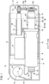
Fig. 1 is a partially omitted schematic plan view of a liquid medicine administration device according to an embodiment of the present invention. -
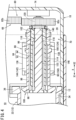
Fig. 2 is a partially omitted cross-sectional view of the liquid medicine administration device inFig. 1 . -
Fig. 3 is a perspective view of a gasket inFig. 2 . -
Fig. 4 is a partially enlarged cross-sectional view of the liquid medicine administration device inFig. 2 . -
Fig. 5 is a transverse cross-sectional view taken along line V-V inFig. 2 . -
Fig. 6 is a partially exploded perspective view of a pressing mechanism inFig. 2 . -
Fig. 7 is an explanatory cross-sectional view illustrating a state where a drive unit is pushed into a housing such that a connection needle penetrates a sealing member. -
Fig. 8 is an explanatory cross-sectional view illustrating a state where a protruding end of a first protrusion of a first fitting portion and a protruding end of a second protrusion of a second fitting portion are in contact with each other. -
Fig. 9 is an explanatory cross-sectional view illustrating a state where the second fitting portion is fitted to the first fitting portion. -
Fig. 10 is a transverse cross-sectional view taken along line X-X inFig. 9 . -
Fig. 11 is a cross-sectional explanatory view illustrating a state where the gasket is pressed to the most distal end in a liquid medicine container. - As illustrated in
Fig. 1 , a liquidmedicine administration device 10 according to an embodiment of the present invention is used for administering a liquid medicine M into a living body. The liquidmedicine administration device 10 continuously administers the liquid medicine M in a prefilledsyringe 14 into the living body over a relatively long time (for example, about several minutes to several hours). The liquidmedicine administration device 10 may intermittently administer the liquid medicine M into the living body. Examples of the liquid medicine M include protein preparations, narcotic analgesics, and diuretics. - The liquid
medicine administration device 10 includes ahousing 12, theprefilled syringe 14, apuncture unit 16, and adrive unit 18. - The
housing 12 extends along an axial direction (arrow X direction) of theprefilled syringe 14. Thehousing 12 is formed, for example, by joining two cover members to each other in a thickness direction of thehousing 12 orthogonal to the arrow X direction (direction orthogonal to the paper surface ofFig. 1 ). Note thatFig. 1 does not illustrate one (upper) cover member of thehousing 12. - The
housing 12 houses thepuncture unit 16, theprefilled syringe 14, and thedrive unit 18. Thepuncture unit 16 is attached to one end (end in an arrow X1 direction) of thehousing 12. The other end (end in an arrow X2 direction) of thehousing 12 is provided with anopening 20 for inserting thedrive unit 18 into thehousing 12. - An insertion hole (not illustrated) through which a
puncture needle 58 forming thepuncture unit 16 is inserted is formed in a wall portion of thehousing 12 to which thepuncture unit 16 is attached. An adhesive sheet (not illustrated) for attaching the liquidmedicine administration device 10 to skin of the living body is fixed to an outer surface of the wall portion. - As illustrated in
Fig. 2 , the prefilledsyringe 14 includes aliquid medicine container 22, a liquid medicine M, agasket 26, a sealingmember 28, and adistal end cap 30. - The
liquid medicine container 22 stores the liquid medicine M. Theliquid medicine container 22 is formed in a hollow cylindrical shape having aliquid medicine chamber 32 therein. Theliquid medicine container 22 includes abody portion 34, aflange portion 36, ashoulder portion 38, and anozzle 40. Thebody portion 34 extends along the axial direction (arrow X direction) of theprefilled syringe 14. An inner diameter and an outer diameter of thebody portion 34 are constant (substantially constant) over an entire length of thebody portion 34. A proximal end opening is formed at a proximal end of thebody portion 34. Theflange portion 36 protrudes radially outward from the proximal end (end in the arrow X2 direction) of thebody portion 34 and extends annularly. - A diameter of the
shoulder portion 38 decreases from the distal end (end in the arrow X1 direction) of thebody portion 34. Thenozzle 40 protrudes in a distal direction (arrow X1 direction) from a radially inner end of theshoulder portion 38. Thenozzle 40 is formed in a tubular shape. A liquidmedicine discharge port 42 communicating with theliquid medicine chamber 32 is formed on a distal end of thenozzle 40. The inside of theliquid medicine container 22 is filled with the liquid medicine M in advance. - The
gasket 26 includes a gasketmain body 44 and aconnection member 46. The gasketmain body 44 is slidably disposed inside theliquid medicine container 22. The gasketmain body 44 is configured to be made of, for example, an elastic resin material such as a rubber material or an elastomer material. An outer peripheral surface of the gasketmain body 44 is in close contact with an inner peripheral surface of thebody portion 34 of theliquid medicine container 22 in a liquid-tight manner. - In
Fig. 3 , theconnection member 46 is connected to a proximal portion of the gasketmain body 44. Theconnection member 46 is configured to be made of, for example, a resin material or a metal material harder than the material forming the gasketmain body 44. A proximal end surface of theconnection member 46 includes a firstproximal end surface 48 and a secondproximal end surface 50. - The first
proximal end surface 48 is located at the center of the proximal end surface of theconnection member 46. The firstproximal end surface 48 is formed in a circular shape. The firstproximal end surface 48 is a flat surface extending in a direction orthogonal to an axis of theconnection member 46. - The second
proximal end surface 50 is located radially outward of theconnection member 46 with respect to the firstproximal end surface 48. The secondproximal end surface 50 annularly extends so as to surround the firstproximal end surface 48. The secondproximal end surface 50 is inclined in the arrow X2 direction toward the radially outer side of theconnection member 46. - The second
proximal end surface 50 is provided with a firstfitting portion 52 having an uneven shape. The firstfitting portion 52 extends annularly. The firstfitting portion 52 has a shape in which first protrusions 54 (first teeth) and first recesses 56 (first tooth grooves) are alternately arranged in a circumferential direction of theconnection member 46. - Each of the
first protrusions 54 protrudes from the secondproximal end surface 50. Each of thefirst protrusions 54 is formed such that a length (tooth thickness) along the circumferential direction of theconnection member 46 decreases in a protruding direction. Each of thefirst protrusions 54 extends from aboundary 53 between the firstproximal end surface 48 and the secondproximal end surface 50 to an outerperipheral end 55 of the secondproximal end surface 50. Thefirst recess 56 is located between the adjacentfirst protrusions 54. Bottom surfaces of thefirst recesses 56 are formed by the secondproximal end surface 50. - As illustrated in
Fig. 2 , the sealingmember 28 liquid-tightly seals the liquidmedicine discharge port 42 of thenozzle 40. The sealingmember 28 is configured to be made of an elastic resin material such as a rubber material or an elastomer material. Thedistal end cap 30 prevents the sealingmember 28 from coming out of the liquidmedicine discharge port 42. Thedistal end cap 30 is configured to be made of, for example, a hard resin material. - In
Fig. 1 , thepuncture unit 16 includes thepuncture needle 58, aneedle support portion 60, aconnection needle 62, and aneedle coupling portion 64. Thepuncture needle 58 has a needle tip capable of puncturing the skin of the living body. Thepuncture needle 58 is formed in a tubular shape. Thepuncture needle 58 extends along the thickness direction of thehousing 12. Theneedle support portion 60 is arranged in thehousing 12 to support thepuncture needle 58. Thepuncture needle 58 moves in the distal direction of thepuncture needle 58 by operating a puncture switch (not illustrated). - The
connection needle 62 has aneedle tip 66 that can penetrate the sealingmember 28. Theconnection needle 62 is formed in a tubular shape. Theconnection needle 62 extends along the axial direction (arrow X direction) of theprefilled syringe 14. Theneedle tip 66 of theconnection needle 62 faces the arrow X2 direction. In an initial state of the liquidmedicine administration device 10, theneedle tip 66 of theconnection needle 62 is located apart from the sealingmember 28 in the arrow X1 direction. - The
needle coupling portion 64 couples a proximal end of theconnection needle 62 and a proximal end of thepuncture needle 58 to each other. Theneedle coupling portion 64 is a flexible tube that communicates a lumen of theconnection needle 62 and a lumen of thepuncture needle 58 with each other. - The
drive unit 18 presses thegasket 26 in the distal direction. Thedrive unit 18 is slidably inserted into thehousing 12 together with theprefilled syringe 14 in the distal direction (arrow X1 direction) of theprefilled syringe 14. - The
drive unit 18 includes adrive portion 68, apressing mechanism 70, acontroller 72, and adrive cover 74. Thedrive portion 68 includes apower supply unit 76, amotor 78, and apower transmission mechanism 80. Thepower supply unit 76 supplies power to themotor 78 and thecontroller 72. Thepower supply unit 76 is located on the lateral side of theliquid medicine container 22. Thepower supply unit 76 is located in the arrow X2 direction of theneedle support portion 60. - The
power supply unit 76 includes, for example, a plurality of batteries disposed in series in the arrow X direction. The batteries may be either primary batteries or secondary batteries. Thepower supply unit 76 may include one battery or the plurality of batteries as described above. Themotor 78 is located in the arrow X2 direction of thepower supply unit 76. Thepower transmission mechanism 80 transmits a rotational driving force of themotor 78 to thepressing mechanism 70. Thepower transmission mechanism 80 includes, for example, adrive gear 82a, anintermediate gear 82b, and a drivengear 82c. Thepower transmission mechanism 80 may adopt an appropriate configuration. - As illustrated in
Figs. 4 and5 , thepressing mechanism 70 includes apusher 84, afeed screw shaft 86, arotation restricting structure 88, and a fitting facilitatingguide portion 90. In the initial state of the liquidmedicine administration device 10, a distal portion of thepusher 84 is located at a proximal portion inside theliquid medicine container 22. Thepusher 84 includes apressing plunger 92 having a tubular shape and anintermediate plunger 94 disposed inside thepressing plunger 92. That is, thepusher 84 has a telescopic structure that can extend in the axial direction. - In
Fig. 6 , the pressingplunger 92 is integrally molded using, for example, a resin material. However, the pressingplunger 92 may be configured to be made of a metal material. Thepressing plunger 92 includes a plungermain body 96, a plungerdistal portion 98, and an outward protrudingportion 100. The plungermain body 96 is formed in a cylindrical shape. Afemale screw 102 is formed at a proximal portion of an inner peripheral surface of the plunger main body 96 (seeFig. 4 ). - The plunger
distal portion 98 is connected to a distal end of the plungermain body 96. An outer diameter of the plungerdistal portion 98 is larger than an outer diameter of the plungermain body 96 and smaller than the inner diameter of thebody portion 34 of theliquid medicine container 22. The plungerdistal portion 98 supports the distal portion of thepressing plunger 92 in a predetermined posture inside theliquid medicine container 22. In other words, the plungerdistal portion 98 suppresses excessive inclination of an axis of thepressing plunger 92 with respect to an axis of theliquid medicine container 22 inside theliquid medicine container 22. - A distal end surface of the
pressing plunger 92 includes a firstdistal end surface 104 and a seconddistal end surface 106. The firstdistal end surface 104 is located at the center of the distal end surface of thepressing plunger 92 and extends in an annular shape. The firstdistal end surface 104 is a flat surface extending in a direction orthogonal to the axis of thepressing plunger 92. - The second
distal end surface 106 is located radially outward of thepressing plunger 92 with respect to the firstdistal end surface 104. The seconddistal end surface 106 extends annularly so as to surround the firstdistal end surface 104. The seconddistal end surface 106 is inclined in the arrow X2 direction toward the radially outer side of thepressing plunger 92. - The second
distal end surface 106 is provided with a secondfitting portion 108 having an uneven shape to be fitted to the firstfitting portion 52. The secondfitting portion 108 extends annularly. The secondfitting portion 108 has a shape in which second protrusions 110 (second teeth) and second recesses 112 (second tooth grooves) are alternately arranged in a circumferential direction of thepressing plunger 92. - Each of the
second protrusions 110 protrudes from the seconddistal end surface 106. Each of thesecond protrusions 110 is formed such that a length (tooth thickness) along a circumferential direction of the plungerdistal portion 98 decreases in a protruding direction. Each of thesecond protrusions 110 extends from aboundary 105 between the firstdistal end surface 104 and the seconddistal end surface 106 to ah outerperipheral end 107 of the seconddistal end surface 106. Thesecond recess 112 is located between the adjacentsecond protrusions 110. Bottom surfaces of thesecond recesses 112 are formed by the seconddistal end surface 106. - The
second protrusion 110 and thesecond recess 112 are formed so as to be fittable to thefirst recess 56 and thefirst protrusion 54, respectively. Rotation of the pressing plunger 92 (pusher 84) with respect to the connection member 46 (gasket 26) is restricted in a state where the secondfitting portion 108 is fitted to the firstfitting portion 52. Shapes, sizes, numbers, arrangements, and the like of thefirst protrusions 54, thefirst recesses 56, thesecond protrusions 110, and thesecond recesses 112 can be appropriately set. - The outward protruding
portion 100 protrudes radially outward from an intermediate portion of an outer peripheral surface of the plungermain body 96. The outward protrudingportion 100 is a plate-like portion extending in a circumferential direction of the plungermain body 96. The outward protrudingportion 100 supports an intermediate portion of thepressing plunger 92 in a predetermined posture inside theliquid medicine container 22. In other words, the outward protrudingportion 100 prevents the axis of thepressing plunger 92 from being excessively inclined with respect to the axis of theliquid medicine container 22 inside theliquid medicine container 22. - The
intermediate plunger 94 is formed in a cylindrical shape. In the initial state of the liquidmedicine administration device 10, a distal end of theintermediate plunger 94 does not protrude in the distal direction from a distal end of thepressing plunger 92. Theintermediate plunger 94 is spaced apart from theliquid medicine container 22. - As illustrated in
Fig. 4 , a male screw 114 screwed into thefemale screw 102 of thepressing plunger 92 is formed on an outer peripheral surface of theintermediate plunger 94. The male screw 114 is not formed at a distal portion of the outer peripheral surface of theintermediate plunger 94. In other words, a distal end of the male screw 114 is located in a proximal direction (arrow X2 direction) with respect to the distal end of theintermediate plunger 94. Therefore, the pressingplunger 92 does not come out of theintermediate plunger 94 in the distal direction. Note that a proximal end of the male screw 114 is located at a proximal end of theintermediate plunger 94. Afemale screw 116 is formed at a proximal portion of an inner peripheral surface of theintermediate plunger 94. - The
feed screw shaft 86 includes arod portion 118 and acoupling portion 120. In the initial state of the liquidmedicine administration device 10, a distal end of therod portion 118 does not protrude in the distal direction from the distal end of thepressing plunger 92.
A male screw 122 screwed into thefemale screw 116 of theintermediate plunger 94 is formed on an outer peripheral surface of therod portion 118. - The male screw 122 is not formed at a distal portion of the outer peripheral surface of the
rod portion 118. In other words, a distal end of the male screw 122 is located in the proximal direction (arrow X2 direction) with respect to a distal end of thefeed screw shaft 86. Therefore, theintermediate plunger 94 does not come out of therod portion 118 in the distal direction. Note that a proximal end of the male screw 122 is located at a proximal end of therod portion 118. Thecoupling portion 120 is connected to the proximal end of therod portion 118. The drivengear 82c of thedrive portion 68 is coupled to thecoupling portion 120. - Such a
pressing mechanism 70 includes the female screw 116 (first screw portion) of theintermediate plunger 94, the male screw 122 (second screw portion) of thefeed screw shaft 86, the male screw 114 (third screw portion) of theintermediate plunger 94, and the female screw 102 (fourth screw portion) of thepressing plunger 92. In thepressing mechanism 70, frictional resistance between thefemale screw 102 of thepressing plunger 92 and the male screw 114 of theintermediate plunger 94 is larger than frictional resistance between the male screw 122 of thefeed screw shaft 86 and thefemale screw 116 of theintermediate plunger 94. - As illustrated in
Figs. 4 to 6 , therotation restricting structure 88 restricts rotation of thepusher 84 along a rotation direction of thefeed screw shaft 86. Therotation restricting structure 88 is formed such that the rotation restriction of thepusher 84 is released before thegasket 26 reaches the most distal end in theliquid medicine container 22 in a state where the secondfitting portion 108 is in contact with the firstfitting portion 52. Therotation restricting structure 88 includes a first restrictingportion 124 and a second restrictingportion 126. The first restrictingportion 124 is provided on the outward protrudingportion 100 of thepusher 84. - In
Fig. 6 , the first restrictingportion 124 includes a firstengaging portion 128 and anabutting portion 130. The firstengaging portion 128 includes a restrictingrecess 132 formed in the outward protrudingportion 100. The restrictingrecess 132 penetrates the outward protrudingportion 100 in the axial direction of thepusher 84. The restrictingrecess 132 is opened radially outward of thepusher 84. - The abutting
portion 130 faces the rotation direction of thefeed screw shaft 86. The abuttingportion 130 is a flat surface. The abuttingportion 130 is at a position rotated by about 180° in the circumferential direction of the plungermain body 96 from the restrictingrecess 132. - The second restricting
portion 126 is attached to a support portion 152 (to be described later) of the drive cover 74 (seeFig. 5 ). The second restrictingportion 126 includes abase portion 134, afirst rib 136, and asecond rib 138. Thebase portion 134 is a plate-like portion disposed on the support portion 152 (seeFig. 5 ). Thebase portion 134 extends along the axial direction of thepusher 84. Thebase portion 134 is provided with abearing 140 that rotatably supports thecoupling portion 120 of thefeed screw shaft 86. - In
Fig. 5 , thefirst rib 136 and thesecond rib 138 protrude in a direction opposite to thesupport portion 152 from both side portions of thebase portion 134 in a width direction. The pusher 84 (plunger main body 96) is located between thefirst rib 136 and thesecond rib 138. As illustrated inFig. 6 , thefirst rib 136 and thesecond rib 138 extend in parallel to each other along the axial direction of thepusher 84. - The
first rib 136 is provided with a secondengaging portion 142 that engages with the first engagingportion 128. The secondengaging portion 142 includes a restrictingprotrusion 144 protruding from a protruding end portion of thefirst rib 136 toward thesecond rib 138. In the initial state of the liquidmedicine administration device 10, the restrictingprotrusion 144 is fitted into the restricting recess 132 (seeFig. 5 ). The restrictingprotrusion 144 extends along the axial direction (arrow X direction) of thepusher 84. - A protruding end surface of the
second rib 138 is provided with astopper portion 146 on which the abuttingportion 130 abuts. Thestopper portion 146 is a flat surface extending along the axial direction of thepusher 84. A length of thestopper portion 146 along the axial direction of thepusher 84 is substantially the same as a length of the restrictingprotrusion 144 along the axial direction of thepusher 84. Therotation restricting structure 88 is formed such that the restrictingrecess 132 is separated from the restrictingprotrusion 144 when the abuttingportion 130 is separated from thestopper portion 146 in a case where the pusher 84 (pressing plunger 92) is moved in the distal direction with respect to thefeed screw shaft 86. - When a protruding end of the
second protrusion 110 comes into contact with a protruding end of thefirst protrusion 54 and the secondfitting portion 108 is not fitted to the firstfitting portion 52, the fitting facilitatingguide portion 90 guides a guidedportion 149 provided in thepusher 84 with the rotation of thefeed screw shaft 86 such that thepusher 84 rotates while moving in the distal direction to fit the secondfitting portion 108 to the firstfitting portion 52. In the present embodiment, the guidedportion 149 is the abuttingportion 130 of the first restrictingportion 124. - The fitting facilitating
guide portion 90 is integrally molded with the second restrictingportion 126. The fitting facilitatingguide portion 90 includes aninclined surface 150 continuous to thestopper portion 146. - The
inclined surface 150 is inclined in a circumferential direction of the pusher 84 (the circumferential direction of the pressing plunger 92) toward the distal direction of thepusher 84. Theinclined surface 150 terminates at a position rotated by about 90° in the circumferential direction of thepusher 84 from a boundary portion with the stopper portion 146 (seeFig. 5 ). Theinclined surface 150 is a flat surface. - In
Fig. 1 , thecontroller 72 controls an operation of themotor 78. Thedrive cover 74 integrally supports thepower supply unit 76, themotor 78, thepower transmission mechanism 80, thepusher 84, and thecontroller 72. Thedrive cover 74 includes thesupport portion 152 that supports theliquid medicine container 22 of the prefilled syringe 14 (seeFig. 5 ). - Next, a method for using the liquid
medicine administration device 10 will be described. As illustrated inFig. 2 , in the initial state of the liquidmedicine administration device 10, the secondfitting portion 108 is located apart from the firstfitting portion 52 in the proximal direction (arrow X2 direction). In addition, the sealingmember 28 of theprefilled syringe 14 is located apart from theneedle tip 66 of theconnection needle 62 in the arrow X2 direction. - When the liquid
medicine administration device 10 is used, as illustrated inFig. 7 , a user pushes thedrive unit 18 in the arrow X1 direction with respect to thehousing 12 to cause theconnection needle 62 to penetrate the sealingmember 28 of theprefilled syringe 14. As a result, the lumen of the puncture needle 58 (seeFig. 1 ) and theliquid medicine chamber 32 communicate with each other via theconnection needle 62 and theneedle coupling portion 64. - In the liquid
medicine administration device 10, thecontroller 72 drives themotor 78 to administer the liquid medicine M. When themotor 78 is driven, the rotational driving force of themotor 78 is transmitted to thefeed screw shaft 86 via the power transmission mechanism 80 (thedrive gear 82a, theintermediate gear 82b, and the drivengear 82c), and thefeed screw shaft 86 rotates, so that torque acts on thepusher 84. - At this time, since the restricting
protrusion 144 is fitted to the restrictingrecess 132 and the abuttingportion 130 abuts on thestopper portion 146, the rotation of thepressing plunger 92 along the rotation direction of thefeed screw shaft 86 is restricted. Therefore, the pusher 84 (thepressing plunger 92 and the intermediate plunger 94) linearly moves in the distal direction with respect to thefeed screw shaft 86. Then, the secondfitting portion 108 of thepusher 84 comes into contact with the firstfitting portion 52 of thegasket 26. - At this time, there is a case where the protruding end of the
first protrusion 54 of the firstfitting portion 52 and the protruding end of thesecond protrusion 110 of the secondfitting portion 108 come into contact with each other so that the secondfitting portion 108 is not fitted to the firstfitting portion 52 depending on the dimensional tolerance and the assembly tolerance of the components of the liquidmedicine administration device 10 as illustrated inFig. 8 . In such a case, thepusher 84 whose rotation is restricted by therotation restricting structure 88 presses thegasket 26 in the distal direction (arrow X1 direction) while the protruding end of thefirst protrusion 54 is in contact with the protruding end of thesecond protrusion 110. As a result, thegasket 26 moves inside theliquid medicine container 22 in the distal direction, and the liquid medicine M in theliquid medicine container 22 is administered into the living body via thepuncture unit 16. - Then, when the restricting
recess 132 is detached (separated) from the restrictingprotrusion 144 and the abuttingportion 130 is separated from thestopper portion 146, the abutting portion 130 (guided portion 149) comes into contact with theinclined surface 150. - Then, when the
feed screw shaft 86 further rotates, the abuttingportion 130 moves while making contact with theinclined surface 150 as illustrated inFigs. 9 and10 , so that the pusher 84 (pressing plunger 92) moves in the distal direction (arrow X1 direction) with respect to thefeed screw shaft 86 while rotating in the rotation direction of thefeed screw shaft 86. As a result, the secondfitting portion 108 is fitted to the first fitting portion 52 (thesecond protrusion 110 is fitted into thefirst recess 56, and thefirst protrusion 54 is fitted into the second recess 112). - When the second
fitting portion 108 is fitted to the firstfitting portion 52, the rotation of thepusher 84 along the rotation direction of thefeed screw shaft 86 is restricted by a frictional force generated between the outer peripheral surface of the gasketmain body 44 and the inner peripheral surface of thebody portion 34 of theliquid medicine container 22. Therefore, thepusher 84 linearly moves in the distal direction (arrow X1 direction) with the rotation of thefeed screw shaft 86. Note that, when the secondfitting portion 108 is fitted to the firstfitting portion 52, thepusher 84 does not rotate with respect to thefeed screw shaft 86, so that the abuttingportion 130 is spaced apart from theinclined surface 150. As illustrated inFig. 11 , thegasket 26 moves to the most distal end in theliquid medicine container 22, whereby all the liquid medicine M in theliquid medicine container 22 is administered into the living body. - In the above description, the case where the protruding end of the
second protrusion 110 comes into contact with the protruding end of thefirst protrusion 54 and the secondfitting portion 108 is not fitted to the firstfitting portion 52 when thepusher 84 of the liquidmedicine administration device 10 in the initial state moves in the distal direction and the secondfitting portion 108 comes into contact with the firstfitting portion 52 has been exemplified. In this case, the secondfitting portion 108 is fitted to the firstfitting portion 52 by the fitting facilitatingguide portion 90 as described above. - On the other hand, in the present embodiment, there is also a case where the first
fitting portion 52 is fitted to the secondfitting portion 108 when thepusher 84 of the liquidmedicine administration device 10 in the initial state moves in the distal direction and the firstfitting portion 52 comes into contact with the secondfitting portion 108 depending on the dimensional tolerance and the assembly tolerance of the components of the liquidmedicine administration device 10. In such a case, when the secondfitting portion 108 is fitted to the firstfitting portion 52, the frictional force generated between the outer peripheral surface of the gasketmain body 44 and the inner peripheral surface of thebody portion 34 of theliquid medicine container 22 restricts the rotation of thepusher 84 along the rotation direction of thefeed screw shaft 86. Therefore, when the restrictingrecess 132 is detached from the restrictingprotrusion 144 and the abuttingportion 130 is separated from thestopper portion 146, thepusher 84 moves in the distal direction without being rotated by thefeed screw shaft 86. That is, since the abuttingportion 130 does not come into contact with theinclined surface 150, the function of the fitting facilitatingguide portion 90 is not exerted. - The present embodiment has the following effects.
- According to the present embodiment, the
pusher 84 is disposed apart from thegasket 26 in the proximal direction in the initial state of the liquidmedicine administration device 10, so that the liquid medicine M in theliquid medicine container 22 can be maintained in an aseptic state. When thedrive portion 68 rotates thefeed screw shaft 86, the rotation of thepusher 84 along the rotation direction of thefeed screw shaft 86 is restricted by therotation restricting structure 88, so that thepusher 84 moves in the distal direction, and the secondfitting portion 108 of thepusher 84 comes into contact with the firstfitting portion 52 of thegasket 26. Then, when the secondfitting portion 108 is fitted to the firstfitting portion 52, the rotation restriction of thepusher 84 is switched from therotation restricting structure 88 to the frictional force generated between thegasket 26 and theliquid medicine container 22 before thegasket 26 reaches the most distal end in theliquid medicine container 22. As a result, the liquidmedicine administration device 10 can be downsized as compared with a case where the rotation of thepusher 84 is restricted by therotation restricting structure 88 until thegasket 26 reaches the most distal end in theliquid medicine container 22. - In addition, there is a case where the protruding end of the
first protrusion 54 of the firstfitting portion 52 and the protruding end of thesecond protrusion 110 of the secondfitting portion 108 come into contact with each other so that the secondfitting portion 108 is not fitted to the firstfitting portion 52 depending on the dimensional tolerance and the assembly tolerance of the components of the liquidmedicine administration device 10. Even in such a case, thepusher 84 rotates while moving in the distal direction by the fitting facilitatingguide portion 90 when the rotation restriction of thepusher 84 by therotation restricting structure 88 is released, so that the secondfitting portion 108 can be fitted to the firstfitting portion 52. Therefore, thegasket 26 can be pressed in the distal direction by thepusher 84. - The
pusher 84 includes theintermediate plunger 94 and thepressing plunger 92. Theintermediate plunger 94 has the female screw 116 (first screw portion) and the male screw 114 (third screw portion). Thepressing plunger 92 has the female screw 102 (fourth screw portion) screwed into the male screw 114 and presses thegasket 26. The distal end of the male screw 122 (second screw portion) of thefeed screw shaft 86 is located in the proximal direction with respect to the distal end of thefeed screw shaft 86. Theintermediate plunger 94 moves in the distal direction with respect to thefeed screw shaft 86 by the rotation of thefeed screw shaft 86, and rotates together with thefeed screw shaft 86 in a state where thefemale screw 116 of theintermediate plunger 94 is located at the distal end of the male screw 122 of thefeed screw shaft 86. Thepressing plunger 92 moves in the distal direction with respect to theintermediate plunger 94 by the rotation of theintermediate plunger 94. - According to such a configuration, since the
pusher 84 can extend, a length of the liquidmedicine administration device 10 along the axial direction of theliquid medicine container 22 can be made short. As a result, the liquidmedicine administration device 10 can be further downsized. - The
intermediate plunger 94 is spaced apart from theliquid medicine container 22. - According to such a configuration, since no frictional force is generated between the
liquid medicine container 22 and theintermediate plunger 94, a driving force required to move thegasket 26 in the distal direction can be efficiently reduced. - The liquid
medicine administration device 10 includes thesupport portion 152 that supports theliquid medicine container 22. Therotation restricting structure 88 includes the first restrictingportion 124 provided in thepusher 84 and the second restrictingportion 126 provided in thesupport portion 152. The first restrictingportion 124 abuts on the second restrictingportion 126 to restrict the rotation of thepusher 84 along the rotation direction of thefeed screw shaft 86. - According to such a configuration, it is possible to restrict the rotation of the
pusher 84 along the rotation direction of thefeed screw shaft 86 with a simple configuration. - The second restricting
portion 126 is located in a direction facing a proximal end surface of theliquid medicine container 22. - According to such a configuration, the
rotation restricting structure 88 can be downsized. - The first restricting
portion 124 has the first engagingportion 128, and the second restrictingportion 126 has the secondengaging portion 142. The firstengaging portion 128 includes the restrictingrecess 132. The secondengaging portion 142 includes the restrictingprotrusion 144 fitted to the restrictingrecess 132. - According to such a configuration, the rotation of the
pusher 84 along the rotation direction of thefeed screw shaft 86 can be efficiently restricted by the restrictingrecess 132 and the restrictingprotrusion 144. - The second
engaging portion 142 extends along the axial direction of thepusher 84. - According to such a configuration, the
pusher 84 can be moved in the distal direction in a state where the rotation of thepusher 84 is restricted with a simple configuration. - The first restricting
portion 124 has the abuttingportion 130 facing the rotational direction of thefeed screw shaft 86. The second restrictingportion 126 has thestopper portion 146 on which the abuttingportion 130 abuts. - According to such a configuration, it is possible to restrict the rotation of the
pusher 84 along the rotation direction of thefeed screw shaft 86 with a simple configuration. - The
stopper portion 146 is a flat surface extending along the axial direction of thepusher 84. - According to such a configuration, the
pusher 84 can be moved in the distal direction in a state where the rotation of thepusher 84 is restricted with a simple configuration. In addition, the torque acting on the pusher 84 (abutting portion 130) can be received by the flat surface. - The guided
portion 149 is provided in the first restrictingportion 124. - According to such a configuration, it is not necessary to provide the guided
portion 149 in thepusher 84 separately from the first restrictingportion 124 so that the configuration of thepusher 84 can be simplified. - The fitting facilitating
guide portion 90 is integrally molded with the second restrictingportion 126. - According to such a configuration, rigidity of the fitting facilitating
guide portion 90 and the second restrictingportion 126 can be enhanced. - The fitting facilitating
guide portion 90 includes theinclined surface 150 inclined in the circumferential direction of thepusher 84 from thestopper portion 146 toward the distal direction of thepusher 84. - According to such a configuration, the first restricting
portion 124 can be smoothly shifted from thestopper portion 146 to theinclined surface 150. - In the initial state of the liquid
medicine administration device 10, a distal portion of thepusher 84 is located at a proximal portion inside theliquid medicine container 22. - According to such a configuration, it is possible to increase the amount of the liquid medicine M that can be stored in the
liquid medicine container 22 while suppressing an increase in size of the liquidmedicine administration device 10. - The present embodiment is not limited to the above-described configuration. The first
engaging portion 128 may have a restricting protrusion, and the secondengaging portion 142 may have a restricting recess. Therotation restricting structure 88 may include only the abuttingportion 130 and thestopper portion 146 without including the first engagingportion 128 and the secondengaging portion 142. In addition, therotation restricting structure 88 may include only the first engagingportion 128 and the secondengaging portion 142 without including the abuttingportion 130 and thestopper portion 146. The firstfitting portion 52 and the secondfitting portion 108 do not necessarily have a gear shape. The shapes, positions, sizes, numbers, and the like of the firstfitting portion 52 and the secondfitting portion 108 can be appropriately set as long as the firstfitting portion 52 and the secondfitting portion 108 can be fitted to each other to restrict the rotation of thepressing plunger 92 with respect to thegasket 26. - Note that the present invention is not limited to the above disclosure, and various configurations can be adopted without departing from the gist of the present invention.
Claims (13)
- A liquid medicine administration device comprising:a liquid medicine container storing a liquid medicine and having a liquid medicine discharge port at a distal end;a gasket liquid-tightly disposed to be slidable in the liquid medicine container;a pressing mechanism comprising a pusher that presses the gasket in a distal direction and a feed screw shaft that has a second screw portion, screwed into a first screw portion provided in the pusher, and moves the pusher in the distal direction; anda drive portion that rotates the feed screw shaft,wherein the gasket comprises a first fitting portion having an uneven shape on a proximal end surface,the pusher comprises a second fitting portion, which has an uneven shape and is fitted to the first fitting portion, on a distal end surface,the second fitting portion is spaced apart from the first fitting portion in a proximal direction in an initial state of the liquid medicine administration device,the pressing mechanism comprisesa rotation restricting structure formed to restrict rotation of the pusher along a rotation direction of the feed screw shaft to move the pusher in the distal direction and bring the second fitting portion into contact with the first fitting portion, and to release the restriction of the rotation of the pusher before the gasket reaches a most distal end in the liquid medicine container in a state where the second fitting portion is in contact with the first fitting portion, anda fitting facilitating guide portion that guides a guided portion provided in the pusher with rotation of the feed screw shaft in such a manner that the pusher rotates while moving in the distal direction to fit the second fitting portion to the first fitting portion when the restriction of the rotation of the pusher by the rotation restricting structure is released in a case where a protruding end of a protrusion of the second fitting portion is in contact with a protruding end of a protrusion of the first fitting portion in a contact state between the first fitting portion and the second fitting portion and the second fitting portion is not fitted to the first fitting portion, andthe rotation of the pusher with respect to the gasket is restricted and the rotation of the pusher is restricted by a frictional force between the gasket and the liquid medicine container in a fitted state where the first fitting portion and the second fitting portion are fitted to each other.
- The liquid medicine administration device according to claim 1, whereinthe pusher comprisesan intermediate plunger having the first screw portion and a third screw portion, anda pressing plunger that has a fourth screw portion screwed into the third screw portion and presses the gasket,a distal end of the second screw portion is located in the proximal direction with respect to a distal end of the feed screw shaft,the intermediate plunger moves in the distal direction with respect to the feed screw shaft by the rotation of the feed screw shaft, and rotates together with the feed screw shaft in a state where the first screw portion is located at the distal end of the second screw portion, andthe pressing plunger moves in the distal direction with respect to the intermediate plunger by the rotation of the intermediate plunger.
- The liquid medicine administration device according to claim 2, wherein
the intermediate plunger is spaced apart from the liquid medicine container. - The liquid medicine administration device according to claim 1, comprising a support portion that supports the liquid medicine container,wherein the rotation restricting structure comprisesa first restricting portion provided in the pusher, anda second restricting portion provided on the support portion, andthe first restricting portion abuts on the second restricting portion to restrict the rotation of the pusher along the rotation direction of the feed screw shaft.
- The liquid medicine administration device according to claim 4, wherein
the second restricting portion is located in a direction facing a proximal end surface of the liquid medicine container. - The liquid medicine administration device according to claim 4, whereinthe first restricting portion comprises a first engaging portion,the second restricting portion comprises a second engaging portion,one of the first engaging portion and the second engaging portion comprises a restricting recess, andanother of the first engaging portion and the second engaging portion comprises a restricting protrusion fitted into the restricting recess.
- The liquid medicine administration device according to claim 6, wherein
the second engaging portion extends along an axial direction of the pusher. - The liquid medicine administration device according to claim 4, whereinthe first restricting portion comprises an abutting portion facing the rotation direction of the feed screw shaft, andthe second restricting portion comprises a stopper portion on which the abutting portion abuts.
- The liquid medicine administration device according to claim 8, wherein
the stopper portion is a flat surface extending along an axial direction of the pusher. - The liquid medicine administration device according to claim 8, wherein
the fitting facilitating guide portion comprises an inclined surface inclined in a circumferential direction of the pusher from the stopper portion toward the distal direction of the pusher. - The liquid medicine administration device according to claim 4, wherein
the guided portion is provided in the first restricting portion. - The liquid medicine administration device according to claim 4, wherein
the fitting facilitating guide portion is integrally molded with the second restricting portion. - The liquid medicine administration device according to any one of claims 1 to 12, wherein
in the initial state, a distal portion of the pusher is located at a proximal portion inside the liquid medicine container.
Applications Claiming Priority (2)
| Application Number | Priority Date | Filing Date | Title |
|---|---|---|---|
| JP2022142253 | 2022-09-07 | ||
| PCT/JP2023/015285 WO2024053149A1 (en) | 2022-09-07 | 2023-04-17 | Drug solution administration device |
Publications (2)
| Publication Number | Publication Date |
|---|---|
| EP4537871A1 true EP4537871A1 (en) | 2025-04-16 |
| EP4537871A4 EP4537871A4 (en) | 2025-09-17 |
Family
ID=90192201
Family Applications (1)
| Application Number | Title | Priority Date | Filing Date |
|---|---|---|---|
| EP23862699.8A Pending EP4537871A4 (en) | 2022-09-07 | 2023-04-17 | Device for administering a medicinal solution |
Country Status (4)
| Country | Link |
|---|---|
| US (1) | US20250186684A1 (en) |
| EP (1) | EP4537871A4 (en) |
| JP (1) | JPWO2024053149A1 (en) |
| WO (1) | WO2024053149A1 (en) |
Families Citing this family (3)
| Publication number | Priority date | Publication date | Assignee | Title |
|---|---|---|---|---|
| WO2016145206A1 (en) | 2015-03-10 | 2016-09-15 | Regeneron Pharmaceuticals, Inc. | Aseptic piercing system and method |
| ES2919934T3 (en) | 2017-05-05 | 2022-07-29 | Regeneron Pharma | Autoinjector and related procedures for use |
| USD1007676S1 (en) | 2021-11-16 | 2023-12-12 | Regeneron Pharmaceuticals, Inc. | Wearable autoinjector |
Family Cites Families (6)
| Publication number | Priority date | Publication date | Assignee | Title |
|---|---|---|---|---|
| DE69928827T2 (en) * | 1998-10-29 | 2006-08-31 | Medtronic MiniMed, Inc., Northridge | RESERVOIR CONNECTION |
| US9173997B2 (en) | 2007-10-02 | 2015-11-03 | Medimop Medical Projects Ltd. | External drug pump |
| US10086145B2 (en) * | 2015-09-22 | 2018-10-02 | West Pharma Services Il, Ltd. | Rotation resistant friction adapter for plunger driver of drug delivery device |
| EP3630226B1 (en) * | 2017-05-30 | 2025-10-22 | West Pharma. Services Il, Ltd. | Modular drive train for wearable injector |
| EP3659650B1 (en) * | 2017-09-29 | 2024-07-03 | Terumo Kabushiki Kaisha | Plunger assembly, drug solution dosage device, and driving method of plunger assembly |
| EP4397336A3 (en) * | 2017-10-16 | 2024-10-09 | Becton, Dickinson and Company | Spacer assembly for drug delivery device |
-
2023
- 2023-04-17 EP EP23862699.8A patent/EP4537871A4/en active Pending
- 2023-04-17 WO PCT/JP2023/015285 patent/WO2024053149A1/en not_active Ceased
- 2023-04-17 JP JP2024545436A patent/JPWO2024053149A1/ja active Pending
-
2025
- 2025-02-20 US US19/058,660 patent/US20250186684A1/en active Pending
Also Published As
| Publication number | Publication date |
|---|---|
| WO2024053149A1 (en) | 2024-03-14 |
| EP4537871A4 (en) | 2025-09-17 |
| JPWO2024053149A1 (en) | 2024-03-14 |
| US20250186684A1 (en) | 2025-06-12 |
Similar Documents
| Publication | Publication Date | Title |
|---|---|---|
| US20250186684A1 (en) | Drug solution administration device | |
| JP7706541B2 (en) | A double acting telescopic screw driven pump mechanism externally disposed in the reservoir of the fluid delivery device | |
| TWI709422B (en) | System for syringe plunger engagement with an injector | |
| EP1461097B1 (en) | Loading mechanism for infusion pump | |
| JP6724133B2 (en) | Chemical dosing device | |
| EP2774637B1 (en) | Cartridge interface assembly | |
| EP0799063B1 (en) | Filling device for a needleless injector cartridge | |
| US6749590B2 (en) | Syringe barrel and plunger assembly having ellipsoidal configurations | |
| US11278675B2 (en) | Plunger assembly, drug solution dosage device, and driving method of plunger assembly | |
| KR20020010649A (en) | Injection device and method for its operation | |
| KR20140042901A (en) | Refill module for an injection device | |
| CN107427639A (en) | Syringe retainer and administration assembly | |
| EP3542772B1 (en) | Drug solution filling unit, drug solution filling set, and filling adapter | |
| CN116020014A (en) | Improved Giving Device | |
| US20210008273A1 (en) | Drug solution administration device | |
| US20250177643A1 (en) | Medical solution administration device and method for manufacturing medical solution administration device | |
| JP6947677B2 (en) | Chemical administration device | |
| JP7411435B2 (en) | Liquid drug administration device | |
| US20240017004A1 (en) | Liquid medicine administration device | |
| US20260083905A1 (en) | Medical device | |
| EP4501374A1 (en) | Puncture device and medicinal solution administering device equipped with puncture device | |
| EP4537874A1 (en) | Puncture device and drug solution administrating device provided with puncture device | |
| WO2025202419A1 (en) | A modular patch injection system | |
| WO2024004329A1 (en) | Liquid medicine administration device | |
| JP2025110908A (en) | Drug administration device |
Legal Events
| Date | Code | Title | Description |
|---|---|---|---|
| STAA | Information on the status of an ep patent application or granted ep patent |
Free format text: STATUS: THE INTERNATIONAL PUBLICATION HAS BEEN MADE |
|
| PUAI | Public reference made under article 153(3) epc to a published international application that has entered the european phase |
Free format text: ORIGINAL CODE: 0009012 |
|
| STAA | Information on the status of an ep patent application or granted ep patent |
Free format text: STATUS: REQUEST FOR EXAMINATION WAS MADE |
|
| 17P | Request for examination filed |
Effective date: 20250111 |
|
| AK | Designated contracting states |
Kind code of ref document: A1 Designated state(s): AL AT BE BG CH CY CZ DE DK EE ES FI FR GB GR HR HU IE IS IT LI LT LU LV MC ME MK MT NL NO PL PT RO RS SE SI SK SM TR |
|
| STAA | Information on the status of an ep patent application or granted ep patent |
Free format text: STATUS: EXAMINATION IS IN PROGRESS |
|
| A4 | Supplementary search report drawn up and despatched |
Effective date: 20250820 |
|
| RIC1 | Information provided on ipc code assigned before grant |
Ipc: A61M 5/142 20060101AFI20250813BHEP Ipc: A61M 5/315 20060101ALI20250813BHEP |
|
| 17Q | First examination report despatched |
Effective date: 20250901 |
|
| DAV | Request for validation of the european patent (deleted) | ||
| DAX | Request for extension of the european patent (deleted) |