EP4537863A1 - Extracorporeal blood treatment apparatus - Google Patents
Extracorporeal blood treatment apparatus Download PDFInfo
- Publication number
- EP4537863A1 EP4537863A1 EP23203654.1A EP23203654A EP4537863A1 EP 4537863 A1 EP4537863 A1 EP 4537863A1 EP 23203654 A EP23203654 A EP 23203654A EP 4537863 A1 EP4537863 A1 EP 4537863A1
- Authority
- EP
- European Patent Office
- Prior art keywords
- fluid
- line
- concentration
- substance
- effluent
- Prior art date
- Legal status (The legal status is an assumption and is not a legal conclusion. Google has not performed a legal analysis and makes no representation as to the accuracy of the status listed.)
- Pending
Links
Images



Classifications
-
- A—HUMAN NECESSITIES
- A61—MEDICAL OR VETERINARY SCIENCE; HYGIENE
- A61M—DEVICES FOR INTRODUCING MEDIA INTO, OR ONTO, THE BODY; DEVICES FOR TRANSDUCING BODY MEDIA OR FOR TAKING MEDIA FROM THE BODY; DEVICES FOR PRODUCING OR ENDING SLEEP OR STUPOR
- A61M1/00—Suction or pumping devices for medical purposes; Devices for carrying-off, for treatment of, or for carrying-over, body-liquids; Drainage systems
- A61M1/34—Filtering material out of the blood by passing it through a membrane, i.e. hemofiltration or diafiltration
- A61M1/3496—Plasmapheresis; Leucopheresis; Lymphopheresis
-
- A—HUMAN NECESSITIES
- A61—MEDICAL OR VETERINARY SCIENCE; HYGIENE
- A61M—DEVICES FOR INTRODUCING MEDIA INTO, OR ONTO, THE BODY; DEVICES FOR TRANSDUCING BODY MEDIA OR FOR TAKING MEDIA FROM THE BODY; DEVICES FOR PRODUCING OR ENDING SLEEP OR STUPOR
- A61M1/00—Suction or pumping devices for medical purposes; Devices for carrying-off, for treatment of, or for carrying-over, body-liquids; Drainage systems
- A61M1/14—Dialysis systems; Artificial kidneys; Blood oxygenators ; Reciprocating systems for treatment of body fluids, e.g. single needle systems for hemofiltration or pheresis
- A61M1/16—Dialysis systems; Artificial kidneys; Blood oxygenators ; Reciprocating systems for treatment of body fluids, e.g. single needle systems for hemofiltration or pheresis with membranes
- A61M1/1601—Control or regulation
- A61M1/1603—Regulation parameters
- A61M1/1605—Physical characteristics of the dialysate fluid
- A61M1/1607—Physical characteristics of the dialysate fluid before use, i.e. upstream of dialyser
-
- A—HUMAN NECESSITIES
- A61—MEDICAL OR VETERINARY SCIENCE; HYGIENE
- A61M—DEVICES FOR INTRODUCING MEDIA INTO, OR ONTO, THE BODY; DEVICES FOR TRANSDUCING BODY MEDIA OR FOR TAKING MEDIA FROM THE BODY; DEVICES FOR PRODUCING OR ENDING SLEEP OR STUPOR
- A61M1/00—Suction or pumping devices for medical purposes; Devices for carrying-off, for treatment of, or for carrying-over, body-liquids; Drainage systems
- A61M1/14—Dialysis systems; Artificial kidneys; Blood oxygenators ; Reciprocating systems for treatment of body fluids, e.g. single needle systems for hemofiltration or pheresis
- A61M1/16—Dialysis systems; Artificial kidneys; Blood oxygenators ; Reciprocating systems for treatment of body fluids, e.g. single needle systems for hemofiltration or pheresis with membranes
- A61M1/1601—Control or regulation
- A61M1/1603—Regulation parameters
- A61M1/1605—Physical characteristics of the dialysate fluid
- A61M1/1609—Physical characteristics of the dialysate fluid after use, i.e. downstream of dialyser
-
- A—HUMAN NECESSITIES
- A61—MEDICAL OR VETERINARY SCIENCE; HYGIENE
- A61M—DEVICES FOR INTRODUCING MEDIA INTO, OR ONTO, THE BODY; DEVICES FOR TRANSDUCING BODY MEDIA OR FOR TAKING MEDIA FROM THE BODY; DEVICES FOR PRODUCING OR ENDING SLEEP OR STUPOR
- A61M1/00—Suction or pumping devices for medical purposes; Devices for carrying-off, for treatment of, or for carrying-over, body-liquids; Drainage systems
- A61M1/14—Dialysis systems; Artificial kidneys; Blood oxygenators ; Reciprocating systems for treatment of body fluids, e.g. single needle systems for hemofiltration or pheresis
- A61M1/16—Dialysis systems; Artificial kidneys; Blood oxygenators ; Reciprocating systems for treatment of body fluids, e.g. single needle systems for hemofiltration or pheresis with membranes
- A61M1/1601—Control or regulation
- A61M1/1619—Sampled collection of used dialysate, i.e. obviating the need for recovery of whole dialysate quantity for post-dialysis analysis
-
- A—HUMAN NECESSITIES
- A61—MEDICAL OR VETERINARY SCIENCE; HYGIENE
- A61M—DEVICES FOR INTRODUCING MEDIA INTO, OR ONTO, THE BODY; DEVICES FOR TRANSDUCING BODY MEDIA OR FOR TAKING MEDIA FROM THE BODY; DEVICES FOR PRODUCING OR ENDING SLEEP OR STUPOR
- A61M1/00—Suction or pumping devices for medical purposes; Devices for carrying-off, for treatment of, or for carrying-over, body-liquids; Drainage systems
- A61M1/14—Dialysis systems; Artificial kidneys; Blood oxygenators ; Reciprocating systems for treatment of body fluids, e.g. single needle systems for hemofiltration or pheresis
- A61M1/16—Dialysis systems; Artificial kidneys; Blood oxygenators ; Reciprocating systems for treatment of body fluids, e.g. single needle systems for hemofiltration or pheresis with membranes
- A61M1/1621—Constructional aspects thereof
- A61M1/165—Constructional aspects thereof with a dialyser bypass on the dialysis fluid line
-
- A—HUMAN NECESSITIES
- A61—MEDICAL OR VETERINARY SCIENCE; HYGIENE
- A61M—DEVICES FOR INTRODUCING MEDIA INTO, OR ONTO, THE BODY; DEVICES FOR TRANSDUCING BODY MEDIA OR FOR TAKING MEDIA FROM THE BODY; DEVICES FOR PRODUCING OR ENDING SLEEP OR STUPOR
- A61M1/00—Suction or pumping devices for medical purposes; Devices for carrying-off, for treatment of, or for carrying-over, body-liquids; Drainage systems
- A61M1/34—Filtering material out of the blood by passing it through a membrane, i.e. hemofiltration or diafiltration
- A61M1/342—Adding solutions to the blood, e.g. substitution solutions
- A61M1/3424—Substitution fluid path
-
- A—HUMAN NECESSITIES
- A61—MEDICAL OR VETERINARY SCIENCE; HYGIENE
- A61M—DEVICES FOR INTRODUCING MEDIA INTO, OR ONTO, THE BODY; DEVICES FOR TRANSDUCING BODY MEDIA OR FOR TAKING MEDIA FROM THE BODY; DEVICES FOR PRODUCING OR ENDING SLEEP OR STUPOR
- A61M1/00—Suction or pumping devices for medical purposes; Devices for carrying-off, for treatment of, or for carrying-over, body-liquids; Drainage systems
- A61M1/36—Other treatment of blood in a by-pass of the natural circulatory system, e.g. temperature adaptation, irradiation ; Extra-corporeal blood circuits
- A61M1/3607—Regulation parameters
- A61M1/3609—Physical characteristics of the blood, e.g. haematocrit, urea
-
- A—HUMAN NECESSITIES
- A61—MEDICAL OR VETERINARY SCIENCE; HYGIENE
- A61M—DEVICES FOR INTRODUCING MEDIA INTO, OR ONTO, THE BODY; DEVICES FOR TRANSDUCING BODY MEDIA OR FOR TAKING MEDIA FROM THE BODY; DEVICES FOR PRODUCING OR ENDING SLEEP OR STUPOR
- A61M1/00—Suction or pumping devices for medical purposes; Devices for carrying-off, for treatment of, or for carrying-over, body-liquids; Drainage systems
- A61M1/36—Other treatment of blood in a by-pass of the natural circulatory system, e.g. temperature adaptation, irradiation ; Extra-corporeal blood circuits
- A61M1/3672—Means preventing coagulation
-
- A—HUMAN NECESSITIES
- A61—MEDICAL OR VETERINARY SCIENCE; HYGIENE
- A61M—DEVICES FOR INTRODUCING MEDIA INTO, OR ONTO, THE BODY; DEVICES FOR TRANSDUCING BODY MEDIA OR FOR TAKING MEDIA FROM THE BODY; DEVICES FOR PRODUCING OR ENDING SLEEP OR STUPOR
- A61M2205/00—General characteristics of the apparatus
- A61M2205/33—Controlling, regulating or measuring
- A61M2205/3306—Optical measuring means
-
- A—HUMAN NECESSITIES
- A61—MEDICAL OR VETERINARY SCIENCE; HYGIENE
- A61M—DEVICES FOR INTRODUCING MEDIA INTO, OR ONTO, THE BODY; DEVICES FOR TRANSDUCING BODY MEDIA OR FOR TAKING MEDIA FROM THE BODY; DEVICES FOR PRODUCING OR ENDING SLEEP OR STUPOR
- A61M2205/00—General characteristics of the apparatus
- A61M2205/70—General characteristics of the apparatus with testing or calibration facilities
-
- A—HUMAN NECESSITIES
- A61—MEDICAL OR VETERINARY SCIENCE; HYGIENE
- A61M—DEVICES FOR INTRODUCING MEDIA INTO, OR ONTO, THE BODY; DEVICES FOR TRANSDUCING BODY MEDIA OR FOR TAKING MEDIA FROM THE BODY; DEVICES FOR PRODUCING OR ENDING SLEEP OR STUPOR
- A61M2230/00—Measuring parameters of the user
- A61M2230/20—Blood composition characteristics
Definitions
- the present disclosure relates to an extracorporeal blood treatment apparatus configured to perform extracorporeal blood treatments, such as dialysis fluid treatments.
- Renal failure produces several physiological derangements. It is no longer possible to balance water and minerals or to excrete daily metabolic load. Toxic end products of metabolism, such as, urea, creatinine, uric acid and others, may accumulate in a patient's blood and tissue.
- Kidney failure therapies include for instance Hemodialysis (HD), Hemofiltration (HF) Hemodiafiltration (HDF).
- the apparatus of the present invention may be used in the context of continuous renal replacement therapies (CRRT) with or without anticoagulation, for example CRRT with or without systemic anticoagulation (e.g., heparin) / with or without regional anticoagulation (e.g., citrate).
- CRRT continuous renal replacement therapies
- systemic anticoagulation e.g., heparin
- regional anticoagulation e.g., citrate
- in-line sensing technology plays an important role in the efficient functioning of the extracorporeal blood treatment apparatuses.
- the general concept of providing a single (e.g., concentration) sensor placed on a by-pass line running between fresh dialysate and effluent and configured for measuring a property of the fresh dialysis fluid and the spent dialysis fluid is known from some prior art documents.
- US5399157 discloses a method and a device for checking the operation of one sensor situated in a dialysis liquid circuit of an artificial kidney.
- the method includes causing a reference liquid of known characteristics to circulate in the extracorporeal blood circuit, taking a measurement to check at least one characteristic of the dialysis liquid through the sensor, calculating the theoretical value of at least one characteristic of the reference liquid on the basis of the measurement, comparing the calculated theoretical value with the known value of the said characteristic of the reference liquid, concluding that the sensor is working properly after the measurement has been taken when the calculated theoretical value is substantially equal to the known value.
- US5744031 discloses an artificial kidney including a measurement structure for measuring a physical characteristic of a fresh dialysis liquid and of used liquid.
- the measurement structure is disposed in a line portion common to a branch circuit to the feeder line of fresh dialysis liquid and to a branch circuit to the discharge line for the used liquid.
- An occluding structure permits the liquid to circulate exclusively in one or the other branch circuit. Due to this arrangement, it is possible to obtain the value of the physical characteristics of a patient's blood by calculation and to adjust the operation of the kidney permanently to a therapeutic objective set by the physician.
- US6623442 discloses a dialysis apparatus including a dialysis liquid circuit for circulating sodium chloride and sodium bicarbonate through a haemodialyzer and a circuit for infusing a patient with a solution containing at least one ionic substance.
- a dialysance detector determines the actual dialysance of the haemodialyzer for sodium and a flow rate detector determines the flow rate of infusion solution such that the concentration of the substance inside the patient's body tends towards a desired concentration as a function of the dialysance, the concentration of the substance in the infusion solution and the desired concentration.
- US2014098359 discloses a method for monitoring a blood treatment of a patient comprising the steps of irradiating a sample of a dialysis liquid used in the treatment with irradiation light of at least a first irradiation wavelength, detecting light emitted by the irradiated sample in at least a first detection wavelength, the detection wavelength being different from the first irradiation wavelength, and determining the presence and/or concentration of an analyte in the sample on the basis of the detected light.
- WO2021205389 discloses a method and a system for providing a personalized hemodialysis treatment to a subject.
- the method includes obtaining concentration of electrolytes and of metabolic content in blood sample flowing into and out of dialyzer through first blood bypass tube and second blood bypass tube in which a first sensor and second sensor are arranged.
- the method includes obtaining concentration of electrolytes and metabolic content in dialysate fluid flowing into and out of dialyzer through a first dialysate duct and a second dialysate duct.
- the first dialysate duct and second dialysate duct are arranged to pass through a third sensor and a fourth sensor. Variations are identified in concentration obtained for electrolytes and metabolic content in blood sample with respect to concentration obtained for electrolytes and metabolic content in dialysate fluid, respectively.
- the present disclosure sets forth extracorporeal blood treatment apparatus, used for performing extracorporeal blood treatments, such as Therapeutic Plasma Exchange (TPE) hemofiltration (HF), hemodialysis (“HD”), hemodiafiltration (“HDF”) as well as the treatments performed during continuous renal replacement treatments (“CRRT”).
- TPE Therapeutic Plasma Exchange
- HD hemodialysis
- HDF hemodiafiltration
- CRRT continuous renal replacement treatments
- an extracorporeal blood treatment apparatus comprises: a filtration unit, the filtration unit having a primary chamber and a secondary chamber separated by a semi-permeable membrane; an extracorporeal blood circuit comprising a blood withdrawal line connected to an inlet of the primary chamber and a blood return line connected to an outlet of the primary chamber, the extracorporeal blood circuit being configured to be connected to a patient; a blood pump active on the extracorporeal blood circuit to pump blood through said extracorporeal blood circuit; a fluid circuit comprising at least one supply line and an effluent line; the at least one supply line being connected to an inlet of the secondary chamber and/or the extracorporeal blood circuit; the effluent line being connected to an outlet of the secondary chamber; a sampling circuit comprising a by-pass line connecting the at least one supply line to the effluent line;
- a monitoring method for monitoring at least one substance into a fluid flowing through a fluid circuit of an extracorporeal blood apparatus of the type comprising a filtration unit, an extracorporeal blood circuit connected to the filtration unit, a fluid circuit comprising at least one supply line and an effluent line, the at least one supply line being connected to the filtration unit and/or the extracorporeal blood circuit, the effluent line being connected to the filtration unit, a sampling circuit comprising a by-pass line connecting the at least one supply line to the effluent line, a fluid pump assembly active on the sampling circuit, a concentrate sensor placed on the by-pass line, the method comprising the following steps:
- the concentrate sensor on the by-pass line is only one for several substances or the concentrate sensor on the by-pass line is one for each substance whose concentration is to be determined. If the concentrate sensor on the by-pass line is only one for several substances it is configured to measure each and every concentration of the several substances.
- no concentrate sensor is provided on the extracorporeal blood circuit for monitoring the concentration of the at least one substance in blood.
- no other concentrate sensor in addition to the concentration sensor on the bypass line is provided on the fluid circuit for monitoring the concentration of the at least one substance, namely for monitoring the same substance(s).
- the fluid circuit comprises: at least one source of supply fluid connected to one end of the at least one supply line; at least one supply pump active on the at least one supply line; optionally an effluent pump active on the effluent line; wherein the at least one fluid is the at least one supply fluid or an effluent fluid flowing out of the secondary chamber;
- the control unit is operatively connected towards the at least one supply pump and to the optional effluent pump and is configured to drive the at least one supply pump and/or the optional effluent pump, and optionally to control valves, to cause the at least one supply fluid to flow into the extracorporeal blood circuit and/or the secondary chamber and to cause the effluent fluid to flow out of the secondary chamber.
- control unit is configured to, or the method provides for, either: drive/ing the fluid pump assembly in the first activated condition and acquire/ing the signal from the concentrate sensor to determine the concentration Csup of the at least one substance into the at least one supply fluid; or drive/ing the fluid pump assembly in the second activated condition and acquire/ing the signal from the concentrate sensor to determine the concentration Ceff of the at least one substance into the effluent fluid.
- control unit is configured to, or the method provides for, both: drive/ing the fluid pump assembly in the first activated condition and acquire/ing the signal from the concentrate sensor to determine the concentration Csup of the at least one substance into the at least one supply fluid; and drive/ing the fluid pump assembly in the second activated condition and acquire/ing the signal from the concentrate sensor to determine the concentration Ceff of the at least one substance into the effluent fluid, particularly wherein driving in the first activated condition and in the second activated condition is performed in sequence in either order.
- control unit is configured to, or the method provides for, stop/ing the at least one supply pump or keep/ing the at least one supply pump stopped while driving the fluid pump assembly in the second activated condition and acquiring the signal from the concentrate sensor to determine the concentration Ceff of the at least one substance into the effluent fluid.
- control unit is configured to, or the method provides for, drive/ing the effluent pump while driving the fluid pump assembly in the second activated condition and acquiring the signal from the concentrate sensor to determine the concentration Ceff of the at least one substance into the effluent fluid.
- control unit is configured to, or the method provides for, estimate/ing a solute removal rate J of the at least one substance.
- the solute removal rate J of the at least one substance is estimated through the following procedure: receiving a flow rate Qeff of the effluent fluid; calculating the solute removal rate J from the concentration Ceff of the at least one substance into the effluent fluid and the flow rate Qeff of the effluent fluid.
- the procedure for estimating the solute removal rate J of the at least one substance further comprises: receiving a flow rate Qsup of the at least one supply fluid; calculating the solute removal rate J also from the concentration Csup of the at least one substance into the at least one supply fluid and the flow rate Qsup of the at least one supply fluid.
- control unit is configured to, or the method provides for, estimate/ing a blood concentration Cb_est of the at least one substance at the inlet of the primary chamber and/or estimate/ing a clearance or dialysance K/D of the at least one substance.
- the blood concentration Cb_est of the at least one substance at the inlet of the primary chamber is the plasma water concentration Cpw
- the at least one substance is calcium, the estimated blood concentration Cb_est being calcium concentration in the blood.
- the estimated blood concentration Cb_est is coincident with the systemic calcium concentration in the patient blood. This is a relevant parameter to know during regional anticoagulation treatments or during cancer treatments with a dialysis apparatus.
- the infusions that may affect the systemic calcium concentration there are the citrate infusion (usually pre-blood pump infusion) and pre-infusion of a substance including calcium ions.
- the clearance or dialysance K/D of the at least one substance is estimated through the following procedure: estimating a blood concentration Cb_est of the same substance at the inlet of the primary chamber; calculating the clearance or dialysance K/D of the at least one substance from the solute removal rate J and the estimated blood concentration Cb_est of the same substance at the inlet of the primary chamber.
- securing equilibrium is achieved by changing the flow rate Qsup of the at least one supply fluid and/or the flow rate Qeff of the effluent fluid and/or a blood flow rate Qb with respect to prescription values set for the extracorporeal blood treatment.
- securing equilibrium is achieved by waiting for a stabilization time after changing the flow rate Qsup of the at least one supply fluid and/or the flow rate Qeff of the effluent fluid and/or a blood flow rate Qb.
- adjusting the flow rate Qeff of the effluent fluid and/or the blood flow rate Qb comprises: decreasing a ratio of the flow rate Qeff of the effluent fluid to the blood flow rate Qb.
- estimating a blood concentration Cb_est of the same substance at the inlet of the primary chamber comprises: recirculating at least part of the effluent fluid from the outlet of the secondary chamber through the sampling circuit and back to the inlet of the secondary chamber; measuring the concentration of said substance, optionally periodically, in the recirculating effluent fluid; waiting until the concentration of said substance becomes stable or extrapolating a steady state concentration of said substance; the estimated blood concentration Cb_est of the substance at the inlet of the primary chamber being, or being derived from, the stable concentration or the extrapolated steady state; optionally setting valves in proper states to route the effluent fluid; optionally recirculating requires activation of the fluid pump assembly.
- the blood concentration Cb of the at least one substance at the inlet of the primary chamber is the plasma water concentration Cpw and the clearance or dialysance Kpw/Dpw is referred to the plasma water concentration Cpw.
- the at least one supply line comprises: a dialysis line connected to the inlet of the secondary chamber, a dialysis pump active on the dialysis line, a source of dialysis fluid connected to one end of the dialysis line; and/or the at least one supply line comprises: at least one replacement infusion line connected to the extracorporeal blood circuit, upstream or downstream of the filtration unit, or directly to the patient, at least one replacement infusion pump active on the at least one replacement infusion line, at least one source of replacement solution connected to one end of the at least one replacement infusion line.
- one or more of the above supply lines may be present on the device at the same time.
- the by-pass line connects the at least one replacement infusion line to the effluent line.
- the by-pass line connects the dialysis line to the effluent line and said by-pass line further comprises a feed line connecting the at least one replacement infusion line to the by-pass line, optionally at a location between the dialysis line and the concentrate sensor.
- control unit is configured to, or the method provides for, routing the replacement solution to the by-pass line.
- control unit is configured to, or the method provides for, routing the replacement solution to the feed line, optionally through at least one valve or clamp.
- the replacement solution flows in the by-pass line through a suction exerted by the fluid pump assembly.
- the replacement solution flows in the feed line through a suction exerted by the fluid pump assembly.
- control unit is configured to, or the method provides for, drive/ing the fluid pump assembly in the first activated condition and acquire/ing the signal from the concentrate sensor to determine the concentration Cr of the at least one substance into the replacement solution and/or to determine the concentration Cdia of the at least one substance into the dialysis fluid.
- recirculating at least part of the effluent fluid comprises: driving the fluid pump assembly to a maximum flow rate.
- recirculating at least part of the effluent fluid comprises: keeping blood flow rate and replacement infusion flow rates upstream of the filtration unit to respective prescribed values, stopping dialysis flow rate and replacement infusion flow rates downstream of the filtration unit, setting effluent flow rate to balance replacement infusion flow rates upstream of the filtration unit.
- control unit is configured to, or the method provides for, rinsing the by-pass line by drive/ing the fluid pump assembly.
- the fluid circuit further comprises: an auxiliary source of an auxiliary fluid connected to the by-pass line at a location between the at least one supply line and the concentrate sensor; optionally the fluid circuit further comprises an auxiliary line connecting the auxiliary source to the by-pass line at a location between the at least one supply line and the fluid pump assembly or connected to the by-pass line at a location between the at least one supply line and the concentrate sensor.
- control unit is configured to, or the method provides for drive/ing the fluid pump assembly, and optionally controlling valves, to cause the auxiliary fluid to flow through the by-pass line.
- the auxiliary fluid is a rinsing fluid and rinses the by-pass line while said auxiliary fluid flows through the by-pass line.
- the rinsing fluid is the same as the supply fluid.
- the auxiliary fluid is a fluid for quality control and the control unit is configured to check the quality of the concentrate sensor while said auxiliary fluid flows through the by-pass line.
- the sampling circuit further comprises an additional line connecting the blood return line to the by-pass line at a location between the at least one supply line and the connection location of the auxiliary line.
- the fluid pump assembly comprises a single reversible pump acting on the by-pass line.
- the single reversible pump is an occlusive pump.
- the fluid pump assembly comprises: a single pump configured to pump always in a same direction; a first by pass branch and a second by-pass branch connecting points of the by-pass line located upstream and downstream of the single pump and assembly valves placed on the first by pass branch on the second by-pass branch and on the by-pass line, wherein the control unit is configured to control the assembly valves such to arrange the fluid pump assembly in the first activated condition or in the second activated condition.
- control unit is configured to, or the method provides for, rinse/ing the by-pass line and the concentrate sensor before and/or after determining the concentration of the at least one substance.
- a valve is operatively active on the by-pass line between the at least one supply line and the fluid pump assembly.
- a connection location of the feed line to the by-pass line is between the valve and the fluid pump assembly.
- a feed valve is operatively active on the feed line.
- an auxiliary valve is operatively active on the auxiliary line.
- the concentrate sensor is positioned between the fluid pump assembly and the at least one supply line.
- the fluid pump assembly is positioned between the concentrate sensor and the at least one supply line.
- the concentrate sensor is an optical sensor, optionally an optical sensor using fluorescence.
- the concentrate sensor is Ion Selective Electrode sensor (ISE).
- control unit is configured to control the extracorporeal blood treatment apparatus to perform an extracorporeal blood treatment on a patient; the control unit being configured determine the concentration of the at least one substance or to monitor the at least one substance during the extracorporeal blood treatment or by interrupting temporarily the extracorporeal blood treatment.
- the sampling circuit is disposable or is part of a disposable set or is connectable to the disposable set, the disposable set comprising the extracorporeal blood circuit and the fluid circuit.
- the apparatus comprises a machine for extracorporeal blood treatment and the disposable set with the sampling circuit, the machine comprising the control unit and actuating devices, like the pumps, and electronic devices, the machine comprising elements to couple or uncouple the disposable set and the sampling circuit to/from the machine.
- the at least one substance may be urea, creatinine, uric acid, glucose, electrolytes, like Na, K, Ca, Mg, chloride, phosphates, lactate.
- the monitoring blood sensor is configured to detect bicarbonate, pH, pCO2, pO2.
- the monitoring method of independent method aspect 2 is for monitoring at least one substance into a fluid flowing through a fluid circuit of an extracorporeal blood apparatus designed for cancer dialysis treatment.
- the at least one substance is calcium.
- the solute removal rate J is measured with a better accuracy from the supply/effluent side than on the blood side. This better accuracy is driven by a larger concentration difference between Ceff and Csup in comparison to the blood inlet-outlet concentration difference and a more accurate estimate/measurement of the fluid flow rate (typically from scales on the fluid side versus volumetric flow from the peristaltic blood pump).
- Another positive aspect of measuring J via supply/effluent data is that it does not require for any assumptions about the solute distribution and possible mass transfer between red blood cells (RBCs) and plasma.
- Extracorporeal blood treatment for example, but not exclusively, renal failure dialysis
- Stage 5 chronic kidney disease or end-stage renal disease.
- some embodiments of extracorporeal blood treatment apparatuses will be firstly described being suitable, or designed, principally (though not exclusively) for intensive care treatments.
- the numeral 1 globally refers to an extracorporeal blood treatment apparatus which may be used for performing Hemodialysis (“HD”), Hemofiltration (“HF”), Hemodiafiltration (“HDF”) as well as the treatments performed during continuous renal replacement therapies (CRRT).
- HD Hemodialysis
- HF Hemofiltration
- HDF Hemodiafiltration
- CRRT continuous renal replacement therapies
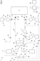
- the extracorporeal blood treatment apparatus 1 comprises a filtration unit 2, of the type having a primary chamber 3 and a secondary chamber 4 separated by a semi-permeable membrane 5, an extracorporeal blood circuit 6 comprising a blood withdrawal line 6a connected to an inlet 3a of the primary chamber 3 of the filtration unit 2, and a blood return line 6b connected to an outlet 3b of the primary chamber 3 of the filtration unit 2.
- the extracorporeal blood circuit 6 is configured to be connected to a patient "P".
- a blood pump 7 is active on the extracorporeal blood circuit 6 to pump blood through said extracorporeal blood circuit 6, from the patient "P" across the blood withdrawal line 6a to the filtration unit 2 and from the filtration unit 2 across the blood return line 6b back to the patient "P".
- the extracorporeal blood treatment apparatus 1 further comprises a fluid circuit 8 comprising a dialysis line 9 and an effluent line 10 connected to the secondary chamber 4.
- the dialysis line 9 has one end connected to an inlet 4a of the secondary chamber 4 and one end connected to a source of dialysis fluid 11, e.g. a bag or a preparation device of fresh dialysis fluid.
- the effluent line 10 has one end connected to an outlet 4b of the secondary chamber 4 and one end connected to a drainage 12.
- a dialysis pump 13 is active on the dialysis line 9 and is able to pump fluid to the second chamber 4.
- An effluent pump 14 is active on the effluent line 10 and is able to draw fluid from the second chamber 4.
- An air detector not shown, and an air separator, such as a deaeration chamber 15, may be present on the blood return line 6b.
- the fluid circuit 8 may also comprise a replacement infusion circuit comprising at least one replacement infusion line connected to the extracorporeal blood circuit 6 or directly to the patient "P", a replacement infusion pump active on the replacement infusion line, a source of replacement solution connected to one end of the replacement infusion line.
- the replacement infusion circuit shown in the embodiment of Figure 1 comprises a pre-blood pump line 16, a pre-infusion line 17 and a post-infusion line 18.
- the dialysis line 9, pre-blood pump line 16, pre-infusion line 17 and post-infusion line 18 are supply lines of the fluid circuit 8.
- the pre-blood pump line 16 is connected to the blood withdrawal line 6a upstream of the blood pump 7 and to a first source 19 of replacement solution, e.g. a bag.
- a pre-blood pump 20 is located on the pre-blood pump line 16 and is able to pump fluid from the first source 19 to the blood circuit.
- the pre-infusion line 17 is connected to the blood withdrawal line 6a downstream of the blood pump 7 and upstream of the filtration unit 2 and to a second source 21 of replacement solution, e.g. a bag.
- a pre-infusion pump 22 is located on the pre-infusion line 17 and is able to pump fluid from the second source 21 to the blood circuit.
- the post-infusion line 18 is connected to the blood return line 6b downstream of the filtration unit 2 and to a third source 23 of replacement solution, e.g. a bag.
- a post-infusion pump 24 is located on the post-infusion line 18 and is able to pump fluid from the third source 23 to the blood circuit.
- the fluid circuit 8 may also comprise one or more further fluid line/s, not shown, connected to the blood circuit and to a source of at least one compensation substance or of an anticoagulant, and a pump or syringe configured to deliver a flow rate of the compensation substance, such as potassium or bicarbonate, etc..
- a withdrawal pressure sensor 25 is configured to detect a pressure at a measurement location in the blood withdrawal line 6a.
- a return pressure sensor 26 is configured to detect a pressure at a measurement location in the blood return line 6b.
- the withdrawal pressure sensor 25 and the return pressure sensor 26 may comprise pressure pods in the blood withdrawal line 6a and blood return line 6b.
- the return pressure sensor 26 may be operatively coupled to the deaeration chamber 15, as shown in Figure 1 .
- a monitor valve, not shown, may be present on the blood return line 6b, downstream the deaeration chamber 15.
- a control unit 100 is configured to control the extracorporeal blood treatment apparatus 1 to perform an extracorporeal blood treatment on the patient "P".
- the control unit 100 is connected and drives the blood pump 7, the dialysis pump 13, the effluent pump 14, the pre-blood pump 20, the pre-infusion pump 22 and the post-infusion pump 24 to regulate a blood flow rate "Qb" in the blood circuit, a supply flow rate crossing the dialysis line 9, an effluent flow rate crossing the effluent line 10, an infusion flow rate crossing the pre-blood pump line 16, an infusion flow rate crossing the pre-infusion line 17, an infusion flow rate crossing the post-infusion line 18.
- control unit 100 is also configured to control/regulate a filtration flow rate in the filtration unit 2 and/or a patient fluid removal rate.
- the control unit 100 is also connected to the withdrawal pressure sensor 25 and to the return pressure sensor 26 to receive signals correlated to pressure values from these sensors 25, 26.
- the control unit 100 may be an electronic control unit comprising at least a CPU, a memory and input/output devices.
- the control unit 100 comprises or is connected to an interface 110 configured to display data and/or allow a user to input data.
- the interface comprises a display, e.g. a touch screen, and/or buttons or a keyboard.
- the apparatus 1 further comprises a sampling circuit 27 comprising a by-pass line 28 having one end connected to the dialysis line 9 of the fluid circuit 8 and another end connected to the effluent line 10 of the fluid circuit 8.
- a fluid pump assembly 29 is active on the sampling circuit 27.
- a concentrate sensor 30 is placed on the by-pass line 28 and is configured for monitoring the concentration of at least one substance detectable into one of the fluids crossing the by-pass line 28, i.e. one or more fluids crossing the fluid circuit 8.
- the fluid pump assembly 29 is a single reversible and occlusive pump acting on the by-pass line 28 and the concentrate sensor 30 is positioned between the fluid pump assembly 29 and the dialysis line 9.
- the fluid pump assembly 29 may be positioned between the concentrate sensor 30 and the dialysis line 9.
- the sampling circuit 27 together with the fluid circuit 8 and the extracorporeal blood circuit 6 may be part of a disposable set which may be mounted to and dismounted from a machine for extracorporeal blood treatment comprising actuating devices, like the pumps, and electronic devices, e.g. the control unit 100.
- the sampling circuit 27 may be a circuit already integrated into the disposable set (being monolithic with the fluid circuit 8) or separate from and connectable to the fluid circuit 8 and/or the extracorporeal blood circuit 6.
- the extracorporeal blood treatment apparatus 1 comprises the machine for extracorporeal blood treatment and the disposable set.
- the concentrate sensor 30 may be an optical sensor which provides for continuous measurements and may be permanently in contact with the fluid to be tested (e.g. an optical sensor using fluorescence). Other type of sensors may alternatively be used such as ion selective sensors. In general, the concentration sensor 30 for measuring the concentration of a specific substance or several different concentrations for several substances of interest may be of different types.
- the concentration sensor 30 may be an ultraviolet (UV) absorbance sensor that measures the absorbance of UV light by the fluid.
- UV absorbance sensor measures the absorbance of UV light by the fluid.
- the concentration sensor 30 may be an ion selective electrode (ISE) to measure specific ions in a solution. They are used to monitor specific electrolytes in the dialysate or the patient's blood, such as potassium or calcium.
- ISE ion selective electrode
- It may be a biosensor, namely a device that uses a biological component (like an enzyme) to detect specific substances. It has potential for measuring specific molecules of interest.
- the concentration sensor 30 may be an optical sensors that employs light properties to measure concentrations of specific solutes. For instance, some optical sensors can detect changes in color or fluorescence related to specific solute concentrations.
- It may be a redox potential sensor to measure the reduction-oxidation potential of the dialysate. It may give insight into the chemical properties and reactions occurring in the dialysate.
- the control unit 100 is connected and controls the fluid pump assembly 29 and is connected to the concentrate sensor 30 to execute a monitoring method for monitoring the concentration of at least one substance in one of the fluids crossing the fluid circuit 8. Since concentration of a substance is desired, the concentration sensor is capable of providing the specific concentration of such a substance (e.g., calcium) without providing a value that includes or is influenced by other solutes, such as sodium.
- concentration sensor is capable of providing the specific concentration of such a substance (e.g., calcium) without providing a value that includes or is influenced by other solutes, such as sodium.
- control unit 100 is configured to drive the fluid pump assembly 29 either in a first activated condition or in a second activated condition.
- the fluid pump assembly 29 causes the fluid in the by-pass line 28 to flow in one direction, from the dialysis line 9 towards the effluent line 10.
- the fluid pump assembly 29 causes the fluid in the by-pass line 28 to flow in an opposite direction, from the effluent line 10 towards the dialysis line 9.
- the fluid pump assembly 29 may be also set in an inactive state in which said fluid pump assembly 29 is stopped and/or at least one valve isolates the sampling circuit 27 from the secondary chamber 4 and from the extracorporeal blood circuit 6.
- the control unit 100 is also configured to receive signals from the concentrate sensor 30 and to determine and monitor the concentration of the at least one substance crossing the by-pass line 28.
- the apparatus 1 of the embodiment of Figure 1 comprises also a feed line 31 having one end connected to the post-infusion line 18, at a location downstream of the post-infusion pump 24, and another end connected to the by-pass line 28, at a connection location between the dialysis line 9 and fluid pump assembly 29.
- a valve 32 is operatively active on the by-pass line 28 between the dialysis line 9 and the feed line 31.
- a feed valve 33 is operatively active on the feed line 31.
- the apparatus 1 of the embodiment of Figure 1 may also comprise (dashed lines) another feed line 34 having one end connected to the pre-blood pump line 16, at a location downstream of the pre-blood pump 20, and another end connected to the by-pass line 28, at a connection location between the dialysis line 9 and the fluid pump assembly 29.
- Another feed valve 35 is operatively active on the other feed line 34.
- the apparatus 1 of the embodiment of Figure 1 may also comprise (dashed lines) a further feed line 36 having one end connected to the pre-infusion line 17, at a location downstream of the pre-infusion pump 22, and another end connected to the by-pass line 28, at a connection location between the dialysis line 9 and the fluid pump assembly 29.
- a further feed valve 37 is operatively active on the further feed line 36.
- a pre- and post-infusion line may be provided, i.e., an infusion line having branches that direct the fluid to the blood withdrawal and to the blood return lines.
- a corresponding feed line having one end connected to the pre- and post-infusion line, at a location downstream of the pump 20 acting on said line (either on the common tract or on the pre-infusion branch or on the post infusion branch), and another end connected to the by-pass line 28.
- a first valve 38, a second valve 39 and a third valve 40 may be operatively active respectively on the post-infusion line 18 (between the feed line 31 and the blood return line 6b), on the pre-blood pump line 16 (between the another feed line 34 and the blood withdrawal line 6a) and on the pre-infusion line 17 (between the further feed line 36 and the blood withdrawal line 6a).
- the control unit 100 is configured to run software routines configured to determine the concentration of the at least one substance or to monitor the at least one substance during the extracorporeal blood treatment or by interrupting temporarily the extracorporeal blood treatment.
- the control unit 100 is configured to run software routines configured to perform several monitoring methods.
- control unit 100 is configured to estimate a filter clearance or dialysance "K/D" of a substance by employing only the concentrate sensor 30 on the by-pass line 28. No other concentrate sensor on the extracorporeal blood circuit 6 is provided or employed for monitoring the concentration of said substance into blood and for calculating the clearance or dialysance "K/D".
- the control unit 100 closes or keeps closed the feed valves 33, 35, 37, opens the valve 32 and drives the fluid pump assembly 29 in the first activated condition to make the dialysis fluid flow from the dialysis line 9 to the effluent line 10 through the by-pass line 28.
- the dialysis fluid interacts with the concentrate sensor 30 and the control unit 100 acquires the signal from the concentrate sensor 30 and determines the concentration "Cdia" of the substance into the dialysis fluid.
- control unit 100 drives the fluid pump assembly 29 in the second activated condition to make the effluent fluid flow from the effluent line 10 to the dialysis line 9 through the by-pass line 28 and acquires the signal from the concentrate sensor 30 to determine the concentration "Ceff" of the substance into the effluent fluid.
- the blood flow rate "Qb" is 200 ml/min
- the prescription value of the flow rate "Qdia” of the dalysate fluid is 2500 ml/h and is decreased to a low value of 1000 ml/h for a time "t" of 5 min.
- a ratio of the low value of the flow rate "Qdia” of the dialysate fluid to the blood flow rate "Qb” is decreased from 0.208 to 0.083.
- control unit 100 stops the fluid pump assembly 29 and may also close the valve 32 and then control the effluent pump 14 to increase the flow rate "Qeff" of the effluent fluid back to the prescription value or above the prescription value to compensate for the decreasing and to achieve a final dose prescription.
- the blood concentration "Cb" of the substance at the inlet 3a of the primary chamber 3 may be estimated through a recirculation method.
- the dialysis pump 13 is stopped, the post-infusion pump 24 is stopped, the pre-blood pump 20 and the pre-infusion pump 22 are kept to their prescribed values, the effluent pump 14 is set to balance pre-dilution infusion(s) and deliver patient fluid removal rate and the fluid pump assembly 29 is driven to a maximum flow rate to recirculate the effluent fluid from the outlet 4b of the secondary chamber 4 through the sampling circuit 27 and back to the inlet 4a of the secondary chamber 4.
- the concentrate sensor 30 measures periodically the concentration of the substance in the recirculating effluent fluid. A steady state concentration of said substance is extrapolated from the plurality of subsequent measures or the measures are performed until the concentration of said substance becomes stable.
- the blood concentration Cb_est of the substance at the inlet 3a of the primary chamber 3 is derived from the stable concentration or as the extrapolated steady state. In addition to calculate filter clearance or dialysance "K/D", the blood concentration Cb_est may be used for other monitoring purposes.
- the flow rate of supply fluid "Qsup” comprise the flow rate "Qdia” of the dialysis fluid and the flow rate of the replacement fluids in the pre-blood pump line 16, pre-infusion line 17 and post-infusion line 18.
- concentrations "Csupi” of the substance to be taken into account is the concentration "Cdia” into the dialysis fluid and the concentrations of the same substance in the replacement fluids of the pre-blood pump line 16, pre-infusion line 17 and post-infusion line 18.
- control unit 100 is configured to determine a concentration of a substance in the pure effluent fluid.
- control unit 100 may be configured to drive the supply pump while also driving the fluid pump assembly 29 in the second activated condition and acquiring the signal from the concentrate sensor 30 to determine the concentration "Ceff" of the substance into the pure effluent fluid.
- control unit 100 is configured to determine a concentration of a substance in the replacement infusion circuit, i.e. in the replacement solution of the first source 19, the second source 21 or the third source 23. This may be carried out as well during system setup as to check for the fluid composition (detection of user errors).
- the control unit 100 closes or keeps closed the feed valve 33 and the further feed valve 37, closes or keeps closed the valve 32, opens the another feed valve 35.
- the control unit 100 keeps on driving the pre-blood pump 20 at its nominal rate and drives the fluid pump assembly 29 in the first activated condition to cause the replacement solution of the first source 19 to flow towards the effluent line 10 through the feed line 34 and the by-pass line 28.
- the fluid pump assembly 29 may be stopped as soon as a predefined volume has been pumped through the circuits 34 and 28 to secure that fluid composition in the sensor 30 is fully representative of first source 19.
- the replacement solution of the first source 19 interacts with the concentrate sensor 30 and the control unit 100 acquires the signal from the concentrate sensor 30 and determines the concentration of the substance into the replacement solution of the first source 19.
- a concentration of a substance in the replacement solution of the second source 21 may be determined by closing or keeping closed the feed valve 33 and the another feed valve 35, closing or keeping closed the valve 32, opening the further feed valve 37 and driving the fluid pump assembly 29 in the first activated condition thus making the replacement solution of the second source 21 to flow towards the effluent line 10 through the by-pass line 28.
- a concentration of a substance in the replacement solution of the third source 23 may be determined by closing or keeping closed the another feed valve 35 and the further feed valve 37, closing or keeping closed the valve 32, opening the feed valve 33 and driving the fluid pump assembly 29 in the first activated condition thus making the replacement solution of the third source 23 to flow towards the effluent line 10 through the by-pass line 28.
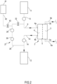
- FIG. 2 shows a second embodiment of a part of the apparatus according to the invention.
- the same reference numerals apply to the same elements of the embodiment of Figure 1 .
- the feed line 31, the other feed line 34 and the further feed line 37 are not depicted but at least one may be present.
- the concentrate sensor 30 of this embodiment is of a type operating intermittently on the fluid to be tested, like an Ion Selective Electrode sensor (ISE) which needs to be rinsed and calibrated before and after the sample measurement.
- ISE Ion Selective Electrode sensor
- this second embodiment further comprises an auxiliary source 41, e.g. a bag, of an auxiliary fluid and an auxiliary line 42 connecting the auxiliary source 41 to the by-pass line 28 at a location between the dialysis line 9 and the fluid pump assembly 29.
- An auxiliary valve 43 is operatively active on the auxiliary line 42 and is operated by the control unit 100.
- the auxiliary fluid in the auxiliary source 41 may be a rinsing fluid and the control unit 100 is configured to rinse the by-pass line 28 and the concentrate sensor 30 before and/or after determining the concentration of the at least one substance.
- the rinsing fluid is configured to rinse the by-pass line 28 while flowing through the by-pass line 28. Rinsing is performed by closing the valve 32, opening the valve 43 and driving the fluid pump assembly 29 in the first activated condition ( Figure 7 ).
- the circuit design is such that the rinsing fluid is then discharged to the drainage 12 and is not infused in the patient "P", so the rinsing fluid may be a sterile fluid not suitable or not approved for infusion in the patient "P".
- the auxiliary fluid in the auxiliary source 41 may be a calibration fluid, i.e. a solution of known concentration of the substance(s) to be measured, and the control unit 100 is configured to calibrate the concentrate sensor 30 before and/or after determining the concentration of the at least one substance.
- the circuit design is such that the calibration fluid is then discharged to the drainage 12 and is not infused in the patient "P", so the calibration fluid may be a sterile fluid not suitable for infusion in the patient "P".
- the auxiliary fluid in the auxiliary source 41 may be a fluid for quality control and the control unit 100 is configured to control the quality of the concentrate sensor 30 before and/or after determining the concentration of the at least one substance.
- the fluid for quality control may be a sterile fluid not suitable for infusion in the patient "P".
- the fluids for quality control may be two different solutions that may be representative of the operating limits of the sensor (concentrations next to the lowest and highest concentrations the device is claimed for).
- the control unit 100 stops the fluid pump assembly 29 when the by-pass line 28 is full of the fluid to be measured (e.g. effluent fluid) and the sensor 30 is filled with said fluid and then the concentration of the substance is measured by the ISE sensor 30. Stopping the fluid pump assembly 29 may be required by sensor technology.
- the fluid to be measured e.g. effluent fluid
- the apparatus 1 may be provided with three different bags all connected to the auxiliary line 42 through valves, one bag with the rinsing fluid, one bag with the calibration fluid and one bag with the fluid for quality control.
- the auxiliary source/s 41 with the rinsing and/or calibration and/or quality control fluids and the auxiliary line 42 may be part of a (disposable) sampling circuit 27 integrating the concentrate sensor 30.
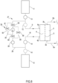
- Figure 3 shows a third embodiment of a part of the apparatus according to the invention.
- the same reference numerals apply to the same elements of the embodiment of Figure 1 .
- the third embodiment is like the second embodiment of Figure 2 with the addition of an additional line 44 connecting the blood return line 6b to the by-pass line 28 at a location between the dialysis line 9 and the connection location of the auxiliary line 42.
- the additional line 44 may have a common section with the post-infusion line 18 (shown in Figure 1 ).
- the positions of the fluid pump assembly 29 and of the concentrate sensor 30 on the by-pass line 28 are swapped.
- some calibration fluid of the auxiliary source 41 may be infused to the patient "P".
- a filter 45 and a further valve 46 are placed on the by-pass line 28 between the effluent line 10 and the fluid pump assembly 29 or the concentrate sensor 12.
- the filter 45 is intended to prevent possible backflow of germs and may be present or not.
- Figure 4 shows a fourth embodiment of a part of the apparatus according to the invention.
- the same reference numerals apply to the same elements of the embodiment of Figure 1 .
- the fourth embodiment is like the first embodiment of Figure 1 with the addition of a monitoring circuit 47 comprising a monitoring line 48 connecting the pre-infusion line 17 to the blood return line 6b.
- a monitoring pump assembly 49 is active on the monitoring line 48 and a monitoring blood sensor 50 is placed on the monitoring line 48.
- a monitoring valve 51 is operative on the monitoring line 48 between the pre-infusion line 17 and the monitoring pump assembly 49.
- a connecting line 52 provided with a connecting valve 53 connects the auxiliary line 42 to the monitoring line 48 at a location between the blood return line 6b and the monitoring blood sensor 50.
- Figure 4 is an example involving two sensors 30, 50, one dedicated to the monitoring of the fluid circuit 8, the other to the monitoring of the extracorporeal blood circuit 6.
- Figure 8 shows a variant embodiment of the fluid pump assembly 29 or of the monitoring pump assembly 49.
- the fluid pump assembly 29 comprises: a single pump 54 configured to pump always in a same direction; a first by pass branch 55 and a second by-pass branch 56 connecting points of the by-pass line 28 located upstream and downstream of the single pump 54 and assembly valves 57, 58, 59, 60 placed on the first by pass branch 55 on the second by-pass branch 56 and on the by-pass line 28, wherein the control unit 100 is configured to control the assembly valves 57, 58, 59, 60 such to arrange the fluid pump assembly 29 in the first activated condition or in the second activated condition.
- a first assembly valve 57 is operative on the first by pass branch 55
- a second assembly valve 58 is operative on the second by pass branch 56.
- a third assembly valve 59 is operative on the by-pass line 28 between a first connection point of the first by pass branch 55 to the by-pass line 28 and a first connection point of the second by pass branch 56 to the by-pass line 28.
- the third assembly valve 59 is positioned between the dialysis line 9 and the single pump 54.
- the first connection point of the first by pass branch 55 is located between the third assembly valve 59 and the dialysis line 9.
- the first connection point of the second by pass branch 56 is located between the third assembly valve 59 and the single pump 54.
- a fourth assembly valve 60 is operative on the by-pass line 28 between a second connection point of the first by pass branch 55 to the by-pass line 28 and a second connection point of the second by pass branch 56 to the by-pass line 28.
- the second connection point of the first by pass branch 55 is located between the fourth assembly valve 60 and the single pump 54.
- the second connection point of the second by pass branch 56 is located between the fourth assembly valve 60 and the effluent line 10.
- the single pump 54 is configured to pump always in a same direction e.g., from to third assembly valve 59 towards the fourth assembly valve 60.
- the control unit 100 is configured to drive the fluid pump assembly 29 in the first activated condition by closing the first assembly valve 57 and the second assembly valve 58 and opening the third assembly valve 59 and the fourth assembly valve 60.
- the control unit 100 is configured to drive the fluid pump assembly 29 in the second activated condition by opening the first assembly valve 57 and the second assembly valve 58 and closing the third assembly valve 59 and the fourth assembly valve 60.
- Figures 9 and 10 show further variants of the fluid circuit 8 provided with the sampling circuit 27. Also in these circuits the same reference numerals apply to the same elements of Figure 1 .
- FIG 9 is a schematic fluid circuit for Therapeutic Plasma Exchange (TPE).
- the fluid circuit 8 comprises the effluent line 10 with the effluent pump 14 and the replacement line 18 with the source 23 of replacement solution and the pump 24.
- the by-pass line 28 connects the effluent line 10 to the replacement line 18.
- Figure 10 is a schematic fluid circuit in which there is no dialysis line 9.
- the by-pass line 28 connects the effluent line 10 to the post-infusion line 18.
- the position of the dialysis pump 13 and of the effluent pump 14 may be different from the position depicted in the drawings.
- the dialysis pump 13 may be placed between a branching point of the by-pass line 28 from the dialysis line 9 and the inlet 4a of the secondary chamber 4 and/or the effluent pump 14 may be placed between the drainage 12 and a connection point of the by-pass line 28 to the effluent line 10.
- the present monitoring method may be advantageously used for monitoring calcium in connection with cancer dialysis.
- cancer-associated hypercalcemia (CAH) is the most frequent metabolic disorder in cancer patients.
- CAH is still associated with poor outcome.
- Hypercalcemia is a condition where there is too much calcium in the blood. It is the most common life-threatening complication of cancer in adults.
- Hypercalcemia develops in 10% to 20% of adults with cancer and is a complication that develops in 10% to 20% of patients with cancer. Cancer-associated hypercalcemia often occurs late in the course of solid-tumor development and portends a poor prognosis. The management of hypercalcemia is based on the presence of characteristic symptomatology and the severity of calcium elevation. Patients with hypercalcemia of malignancy are typically symptomatic and have markedly elevated calcium levels.
- Dialysis may have a fast impact on calcium reduction, and it remains a viable option to reduce hypercalcemia.
- Patients with acute hypercalcaemia may be considered for haemodialysis using a very low calcium dialysate ( ⁇ 1 mmol/L), and monitoring of the blood calcium concentration with the concentration sensor of embodiments of the present description may offer significant advantages for feedback of therapy.
Landscapes
- Health & Medical Sciences (AREA)
- Heart & Thoracic Surgery (AREA)
- Vascular Medicine (AREA)
- Life Sciences & Earth Sciences (AREA)
- Engineering & Computer Science (AREA)
- Anesthesiology (AREA)
- Biomedical Technology (AREA)
- Hematology (AREA)
- Animal Behavior & Ethology (AREA)
- General Health & Medical Sciences (AREA)
- Public Health (AREA)
- Veterinary Medicine (AREA)
- Urology & Nephrology (AREA)
- Emergency Medicine (AREA)
- Cardiology (AREA)
- External Artificial Organs (AREA)
Abstract
Description
- The present disclosure relates to an extracorporeal blood treatment apparatus configured to perform extracorporeal blood treatments, such as dialysis fluid treatments.
- Due to various causes, a person's renal system can fail. Renal failure produces several physiological derangements. It is no longer possible to balance water and minerals or to excrete daily metabolic load. Toxic end products of metabolism, such as, urea, creatinine, uric acid and others, may accumulate in a patient's blood and tissue.
- Reduced kidney function and, above all, kidney failure is treated with dialysis. Dialysis removes waste, toxins and excess water from the body that normal functioning kidneys would otherwise remove. Dialysis treatment for replacement of kidney functions is critical to many people because the treatment is lifesaving. Kidney failure therapies include for instance Hemodialysis (HD), Hemofiltration (HF) Hemodiafiltration (HDF).
- The apparatus of the present invention may be used in the context of continuous renal replacement therapies (CRRT) with or without anticoagulation, for example CRRT with or without systemic anticoagulation (e.g., heparin) / with or without regional anticoagulation (e.g., citrate).
- Irrespective of the type of therapy and/or treatment referred to, in-line sensing technology plays an important role in the efficient functioning of the extracorporeal blood treatment apparatuses.
- For instance, the general concept of providing a single (e.g., concentration) sensor placed on a by-pass line running between fresh dialysate and effluent and configured for measuring a property of the fresh dialysis fluid and the spent dialysis fluid is known from some prior art documents.
-
US2014190876 refers to systems and methods for utilizing a sorbent cartridge and quantifying chemistry changes that occur as dialysate passes through material layers of the cartridge as a means to determine solute concentrations in the solution flowing through the cartridge. The systems and methods disclosed can be used for managing blood urea and quantifying urea clearance during dialysis therapy also including hemodialysis, hemodiafiltration, hemofiltration and peritoneal dialysis. A fluid circuit equipped with a single conductivity sensor is active on a by-pass circuit parallel to the dialyzer. The by-pass circuit allows the diversion of a portion of the dialysate around the dialyzer to rejoin the flow path in the post-dialyzer flow path. -
US5399157 discloses a method and a device for checking the operation of one sensor situated in a dialysis liquid circuit of an artificial kidney. The method includes causing a reference liquid of known characteristics to circulate in the extracorporeal blood circuit, taking a measurement to check at least one characteristic of the dialysis liquid through the sensor, calculating the theoretical value of at least one characteristic of the reference liquid on the basis of the measurement, comparing the calculated theoretical value with the known value of the said characteristic of the reference liquid, concluding that the sensor is working properly after the measurement has been taken when the calculated theoretical value is substantially equal to the known value. -
US5744031 discloses an artificial kidney including a measurement structure for measuring a physical characteristic of a fresh dialysis liquid and of used liquid. The measurement structure is disposed in a line portion common to a branch circuit to the feeder line of fresh dialysis liquid and to a branch circuit to the discharge line for the used liquid. An occluding structure permits the liquid to circulate exclusively in one or the other branch circuit. Due to this arrangement, it is possible to obtain the value of the physical characteristics of a patient's blood by calculation and to adjust the operation of the kidney permanently to a therapeutic objective set by the physician. -
US6623442 discloses a dialysis apparatus including a dialysis liquid circuit for circulating sodium chloride and sodium bicarbonate through a haemodialyzer and a circuit for infusing a patient with a solution containing at least one ionic substance. A dialysance detector determines the actual dialysance of the haemodialyzer for sodium and a flow rate detector determines the flow rate of infusion solution such that the concentration of the substance inside the patient's body tends towards a desired concentration as a function of the dialysance, the concentration of the substance in the infusion solution and the desired concentration. -
US2014098359 discloses a method for monitoring a blood treatment of a patient comprising the steps of irradiating a sample of a dialysis liquid used in the treatment with irradiation light of at least a first irradiation wavelength, detecting light emitted by the irradiated sample in at least a first detection wavelength, the detection wavelength being different from the first irradiation wavelength, and determining the presence and/or concentration of an analyte in the sample on the basis of the detected light.
WO2021205389 discloses a method and a system for providing a personalized hemodialysis treatment to a subject. The method includes obtaining concentration of electrolytes and of metabolic content in blood sample flowing into and out of dialyzer through first blood bypass tube and second blood bypass tube in which a first sensor and second sensor are arranged. The method includes obtaining concentration of electrolytes and metabolic content in dialysate fluid flowing into and out of dialyzer through a first dialysate duct and a second dialysate duct. The first dialysate duct and second dialysate duct are arranged to pass through a third sensor and a fourth sensor. Variations are identified in concentration obtained for electrolytes and metabolic content in blood sample with respect to concentration obtained for electrolytes and metabolic content in dialysate fluid, respectively. - The present disclosure sets forth extracorporeal blood treatment apparatus, used for performing extracorporeal blood treatments, such as Therapeutic Plasma Exchange (TPE) hemofiltration (HF), hemodialysis ("HD"), hemodiafiltration ("HDF") as well as the treatments performed during continuous renal replacement treatments ("CRRT").
- In light of the disclosure set forth herein, and without limiting the disclosure in any way, in a 1st independent aspect, which may be combined with any other aspect or portion thereof described herein, an extracorporeal blood treatment apparatus comprises: a filtration unit, the filtration unit having a primary chamber and a secondary chamber separated by a semi-permeable membrane; an extracorporeal blood circuit comprising a blood withdrawal line connected to an inlet of the primary chamber and a blood return line connected to an outlet of the primary chamber, the extracorporeal blood circuit being configured to be connected to a patient; a blood pump active on the extracorporeal blood circuit to pump blood through said extracorporeal blood circuit; a fluid circuit comprising at least one supply line and an effluent line; the at least one supply line being connected to an inlet of the secondary chamber and/or the extracorporeal blood circuit; the effluent line being connected to an outlet of the secondary chamber; a sampling circuit comprising a by-pass line connecting the at least one supply line to the effluent line; a fluid pump assembly active on the sampling circuit, the fluid pump assembly being drivable between a first activated condition, in which the fluid pump assembly causes at least one fluid crossing the fluid circuit to flow through the by-pass line from the at least one supply line to the effluent line, and a second activated condition, in which the fluid pump assembly causes at least one fluid crossing the fluid circuit to flow through the by-pass line from the effluent line towards the at least one supply line; a concentrate sensor placed on the by-pass line for monitoring the concentration of at least one substance detectable into the at least one fluid crossing the fluid circuit; a control unit operatively connected to the concentration sensor and to the fluid pump assembly, the control unit being configured to drive the fluid pump assembly either in the first activated condition or in the second activated condition and to receive signals from the concentrate sensor and determine the concentration of the at least one substance; optionally a filter placed on the by-pass line between the effluent line and the fluid pump assembly or the concentrate sensor. The fluid pump assembly may be also set in an inactive state in which said fluid pump assembly is stopped and/or at least one valve closes the sampling circuit and/or isolates the sampling circuit from the secondary chamber and from the extracorporeal blood circuit.
- In a 2nd independent aspect, which may be combined with any other aspect or portion thereof described herein, a monitoring method for monitoring at least one substance into a fluid flowing through a fluid circuit of an extracorporeal blood apparatus of the type comprising a filtration unit, an extracorporeal blood circuit connected to the filtration unit, a fluid circuit comprising at least one supply line and an effluent line, the at least one supply line being connected to the filtration unit and/or the extracorporeal blood circuit, the effluent line being connected to the filtration unit, a sampling circuit comprising a by-pass line connecting the at least one supply line to the effluent line, a fluid pump assembly active on the sampling circuit, a concentrate sensor placed on the by-pass line, the method comprising the following steps:
- causing at least one fluid crossing the fluid circuit to flow through the by-pass line from the at least one supply line to the effluent line by driving the fluid pump assembly in a first activated condition and monitoring the concentration of at least one substance detectable into the at least one fluid through the concentrate sensor; or
- causing at least one fluid crossing the fluid circuit to flow through the by-pass line from the effluent line towards the at least one supply line by driving the fluid pump assembly in a second activated condition and monitoring the concentration of the at least one substance detectable into the at least one fluid through the concentrate sensor.
- In the following aspects, details are added with regard to both the extracorporeal blood treatment apparatus and the method considered in the previous independent aspects. Each and every aspect relating to the components/elements and/or any feature of each extracorporeal blood treatment apparatus/method considered in the previous independent aspects are clearly combinable with the aspects of the other extracorporeal blood treatment apparatus considered both in the independent aspects and in the dependent aspects.
- In a 3rd aspect according to any one of previous aspects, the concentrate sensor on the by-pass line is only one for several substances or the concentrate sensor on the by-pass line is one for each substance whose concentration is to be determined. If the concentrate sensor on the by-pass line is only one for several substances it is configured to measure each and every concentration of the several substances.
- In a 4th aspect according to any one of previous aspects, no concentrate sensor is provided on the extracorporeal blood circuit for monitoring the concentration of the at least one substance in blood.
- In a 4th bis aspect according to any one of previous aspects, no other concentrate sensor in addition to the concentration sensor on the bypass line is provided on the fluid circuit for monitoring the concentration of the at least one substance, namely for monitoring the same substance(s).
- In a 5th aspect according to any one of previous aspects, the fluid circuit comprises: at least one source of supply fluid connected to one end of the at least one supply line; at least one supply pump active on the at least one supply line; optionally an effluent pump active on the effluent line; wherein the at least one fluid is the at least one supply fluid or an effluent fluid flowing out of the secondary chamber; the control unit is operatively connected towards the at least one supply pump and to the optional effluent pump and is configured to drive the at least one supply pump and/or the optional effluent pump, and optionally to control valves, to cause the at least one supply fluid to flow into the extracorporeal blood circuit and/or the secondary chamber and to cause the effluent fluid to flow out of the secondary chamber.
- In a 6th aspect according to the
previous aspect 5, the control unit is configured to, or the method provides for, either: drive/ing the fluid pump assembly in the first activated condition and acquire/ing the signal from the concentrate sensor to determine the concentration Csup of the at least one substance into the at least one supply fluid; or drive/ing the fluid pump assembly in the second activated condition and acquire/ing the signal from the concentrate sensor to determine the concentration Ceff of the at least one substance into the effluent fluid. - In a 6th bis aspect according to the
previous aspect 5, the control unit is configured to, or the method provides for, both: drive/ing the fluid pump assembly in the first activated condition and acquire/ing the signal from the concentrate sensor to determine the concentration Csup of the at least one substance into the at least one supply fluid; and drive/ing the fluid pump assembly in the second activated condition and acquire/ing the signal from the concentrate sensor to determine the concentration Ceff of the at least one substance into the effluent fluid, particularly wherein driving in the first activated condition and in the second activated condition is performed in sequence in either order. - In a 7th aspect according to the
previous aspect 6, the control unit is configured to, or the method provides for, stop/ing the at least one supply pump or keep/ing the at least one supply pump stopped while driving the fluid pump assembly in the second activated condition and acquiring the signal from the concentrate sensor to determine the concentration Ceff of the at least one substance into the effluent fluid. - In a 8th aspect according to the
previous aspect - In a 9th aspect according to any of the
previous aspects 5 to 8, the control unit is configured to, or the method provides for, estimate/ing a solute removal rate J of the at least one substance. - In a 10th aspect according to the
previous aspect 9, the solute removal rate J of the at least one substance is estimated through the following procedure: receiving a flow rate Qeff of the effluent fluid; calculating the solute removal rate J from the concentration Ceff of the at least one substance into the effluent fluid and the flow rate Qeff of the effluent fluid. - In a 10th bis aspect according to the
previous aspect 10, the solute removal rate J is calculated through the following formula: J = Qeff x Ceff. - In a 10th ter aspect according to the
previous aspect - In a 11th aspect according to the
previous aspect 10 ter, the solute removal rate J is calculated through the following formula: J = Qeff x Ceff - Qsup x Csup; optionally J = Qeff x Ceff - Σ Qsupi x Csupi, wherein index "i" includes all or some of the supply fluids. - In a 12th aspect according to the
previous aspect - In a 12th bis aspect according to the previous aspect the at least one substance is calcium, the estimated blood concentration Cb_est being calcium concentration in the blood. In case all infusions into the extracorporeal blood circuit affecting calcium concentration in the blood are stopper, the estimated blood concentration Cb_est is coincident with the systemic calcium concentration in the patient blood. This is a relevant parameter to know during regional anticoagulation treatments or during cancer treatments with a dialysis apparatus. Among the infusions that may affect the systemic calcium concentration there are the citrate infusion (usually pre-blood pump infusion) and pre-infusion of a substance including calcium ions.
- In a 13th aspect according to the
previous aspect - In a 13th bis aspect according to the
previous aspect - In a 14th aspect according to the
previous aspect 13 bis, wherein securing equilibrium is achieved by changing the flow rate Qsup of the at least one supply fluid and/or the flow rate Qeff of the effluent fluid and/or a blood flow rate Qb with respect to prescription values set for the extracorporeal blood treatment. - In a 15th aspect according to the
previous aspect 14, securing equilibrium is achieved by waiting for a stabilization time after changing the flow rate Qsup of the at least one supply fluid and/or the flow rate Qeff of the effluent fluid and/or a blood flow rate Qb. - In a 16th aspect according to the
previous aspect 15, adjusting the flow rate Qeff of the effluent fluid and/or the blood flow rate Qb comprises: decreasing a ratio of the flow rate Qeff of the effluent fluid to the blood flow rate Qb. - In a 17th aspect according to the
previous aspect 16, adjusting the flow rate Qeff of the effluent fluid and/or the blood flow rate Qb comprises: decreasing the flow rate Qeff of the effluent fluid with respect to a prescription value of said flow rate Qeff of the effluent fluid; optionally decreasing also the flow rate Qsup of the at least one supply fluid accordingly. - In a 18th aspect according to any of the
previous aspects 14 to 17, after estimating the blood concentration (Cb_est) and/or the clearance or dialysance K/D, the control unit is configured to, or the method provides for, moving back the flow rate Qsup of the at least one supply fluid and/or the flow rate Qeff of the effluent fluid and/or a blood flow rate Qb to the prescription values. - In a 19th aspect according to any of the
previous aspects 13 to 18 when according toaspect 8, acquisition of the signal from the concentrate sensor to determine the concentration Ceff of the at least one substance into the effluent fluid is carried out at least twice. - In a 20th aspect according to the
previous aspect 13 bis, wherein, if the extracorporeal blood treatment is either Hemodialysis or Hemodiafiltration, securing equilibrium is achieved by shifting to pure ultrafiltration. - In a 21st aspect according to any of the
previous aspect 14, the stabilization time is 2 min to 20 min, optionally 5 min to 10 min. - In a 21st bis aspect according to
aspects 12 to 13, estimating a blood concentration Cb_est of the same substance at the inlet of the primary chamber comprises: recirculating at least part of the effluent fluid from the outlet of the secondary chamber through the sampling circuit and back to the inlet of the secondary chamber; measuring the concentration of said substance, optionally periodically, in the recirculating effluent fluid; waiting until the concentration of said substance becomes stable or extrapolating a steady state concentration of said substance; the estimated blood concentration Cb_est of the substance at the inlet of the primary chamber being, or being derived from, the stable concentration or the extrapolated steady state; optionally setting valves in proper states to route the effluent fluid; optionally recirculating requires activation of the fluid pump assembly. - In a 22nd aspect according to any of the
previous aspects 13 to 20, the clearance K of the at least one substance is calculated through the following formula: K = J / (Cb_est) or the dialysance D of the at least one substance is calculated through the following formula: D = J / (Cb_est -Csup), wherein Csup is a concentration Cdia of the at least one substance into a dialysis fluid. - In a 23rd aspect according to any of the
previous aspects 13 to 21, the blood concentration Cb of the at least one substance at the inlet of the primary chamber is the plasma water concentration Cpw and the clearance or dialysance Kpw/Dpw is referred to the plasma water concentration Cpw. - In a 24th aspect according to any of the previous aspects 1 to 24, the at least one supply line comprises: a dialysis line connected to the inlet of the secondary chamber, a dialysis pump active on the dialysis line, a source of dialysis fluid connected to one end of the dialysis line; and/or the at least one supply line comprises: at least one replacement infusion line connected to the extracorporeal blood circuit, upstream or downstream of the filtration unit, or directly to the patient, at least one replacement infusion pump active on the at least one replacement infusion line, at least one source of replacement solution connected to one end of the at least one replacement infusion line.
- Of course, one or more of the above supply lines may be present on the device at the same time.
- In a 25th aspect according to
previous aspect 24, the by-pass line connects the at least one replacement infusion line to the effluent line. - In a 26th aspect according to
previous aspect 24, the by-pass line connects the dialysis line to the effluent line and said by-pass line further comprises a feed line connecting the at least one replacement infusion line to the by-pass line, optionally at a location between the dialysis line and the concentrate sensor. - In a 27th aspect according to
previous aspect 25, the control unit is configured to, or the method provides for, routing the replacement solution to the by-pass line. - In a 27th bis aspect according to
previous aspect 26, the control unit is configured to, or the method provides for, routing the replacement solution to the feed line, optionally through at least one valve or clamp. - In a 28th aspect according to
previous aspect - In a 28th bis aspect according to
previous aspect - In a 29th aspect according to
previous aspect 25 to 28 bis, the control unit is configured to, or the method provides for, drive/ing the fluid pump assembly in the first activated condition and acquire/ing the signal from the concentrate sensor to determine the concentration Cr of the at least one substance into the replacement solution and/or to determine the concentration Cdia of the at least one substance into the dialysis fluid. - In a 29th bis aspect according to any of
aspects 24 to 26, when according toaspect 21 bis, recirculating at least part of the effluent fluid comprises: stopping the dialysis pump or keeping on driving the dialysis pump. - In a 29th ter aspect according to the previous aspect, recirculating at least part of the effluent fluid comprises: driving the fluid pump assembly to a maximum flow rate.
- In a 29th quater aspect according to the
aspect 29 bis or 29 ter, recirculating at least part of the effluent fluid comprises: keeping blood flow rate and replacement infusion flow rates upstream of the filtration unit to respective prescribed values, stopping dialysis flow rate and replacement infusion flow rates downstream of the filtration unit, setting effluent flow rate to balance replacement infusion flow rates upstream of the filtration unit. - In a 30th aspect according to any of the previous aspects 1 to 29 quater, the control unit is configured to, or the method provides for, rinsing the by-pass line by drive/ing the fluid pump assembly.
- In a 31st aspect according to any of the previous aspects 1 to 30, the fluid circuit further comprises: an auxiliary source of an auxiliary fluid connected to the by-pass line at a location between the at least one supply line and the concentrate sensor; optionally the fluid circuit further comprises an auxiliary line connecting the auxiliary source to the by-pass line at a location between the at least one supply line and the fluid pump assembly or connected to the by-pass line at a location between the at least one supply line and the concentrate sensor.
- In a 32nd aspect according to
previous aspect 31, the control unit is configured to, or the method provides for drive/ing the fluid pump assembly, and optionally controlling valves, to cause the auxiliary fluid to flow through the by-pass line. - In a 33th aspect according to
previous aspect - In a 34th aspect according to
previous aspect 33, the rinsing fluid is the same as the supply fluid. - In a 35th aspect according to any of the
previous aspects 32 to 34, the auxiliary fluid is a calibration fluid, i.e. a solution of known concentration of the substance(s) to be measured, and the control unit is configured to calibrate the concentrate sensor while said auxiliary fluid flows through the by-pass line. - In a 36th aspect according any of the
previous aspects 32 to 34, the auxiliary fluid is a fluid for quality control and the control unit is configured to check the quality of the concentrate sensor while said auxiliary fluid flows through the by-pass line. - In a 37th aspect according to any of the
previous aspects 31 to 36, the sampling circuit further comprises an additional line connecting the blood return line to the by-pass line at a location between the at least one supply line and the connection location of the auxiliary line. - In a 38th aspect according to any of the
previous aspects 31 to 36 whenaspect 31 is according toaspect 25, the sampling circuit further comprises a monitoring circuit comprising a monitoring line connecting the replacement infusion line to the blood return line, a monitoring pump assembly active on the monitoring line, a monitoring blood sensor placed on the monitoring line, a connecting line connecting the auxiliary line to the monitoring line at a location between the blood return line and the monitoring blood sensor. - In a 39th aspect according to any of the previous aspects 1 to 38, the fluid pump assembly comprises a single reversible pump acting on the by-pass line.
- In a 40th aspect according to the
previous aspect 39, the single reversible pump is an occlusive pump. - In a 40th bis aspect according to any of the previous aspects 1 to 38, the fluid pump assembly comprises: a single pump configured to pump always in a same direction; a first by pass branch and a second by-pass branch connecting points of the by-pass line located upstream and downstream of the single pump and assembly valves placed on the first by pass branch on the second by-pass branch and on the by-pass line, wherein the control unit is configured to control the assembly valves such to arrange the fluid pump assembly in the first activated condition or in the second activated condition.
- In a 41st aspect according to any of the previous aspects 1 to 40, the control unit is configured to, or the method provides for, calibrate/ing the concentrate sensor before and/or after determining the concentration of the at least one substance.
- In a 42nd aspect according to any of the previous aspects 1 to 41, the control unit is configured to, or the method provides for, rinse/ing the by-pass line and the concentrate sensor before and/or after determining the concentration of the at least one substance.
- In a 43rd aspect according to any of the previous aspects 1 to 42, a valve is operatively active on the by-pass line between the at least one supply line and the fluid pump assembly.
- In a 44th aspect according to the
previous aspect 43 together with any of theprevious aspects - In a 45th aspect according to any of the
previous aspects - In a 46th aspect according to any of the
previous aspect 31 to 38, an auxiliary valve is operatively active on the auxiliary line. - In a 47th aspect according to any of the previous aspects 1 to 46, the concentrate sensor is positioned between the fluid pump assembly and the at least one supply line.
- In a 48th aspect according to any of the previous aspects 1 to 46, the fluid pump assembly is positioned between the concentrate sensor and the at least one supply line.
- In a 49th aspect according to any of the previous aspects 1 to 48, the concentrate sensor is an optical sensor, optionally an optical sensor using fluorescence.
- In a 50th aspect according to any of the previous aspects 1 to 48, the concentrate sensor is Ion Selective Electrode sensor (ISE).
- In a 51st aspect according to any of the previous aspects 1 to 50, the control unit is configured to control the extracorporeal blood treatment apparatus to perform an extracorporeal blood treatment on a patient; the control unit being configured determine the concentration of the at least one substance or to monitor the at least one substance during the extracorporeal blood treatment or by interrupting temporarily the extracorporeal blood treatment.
- In a 52nd aspect according to any of the previous aspects 1 to 51, the sampling circuit is disposable or is part of a disposable set or is connectable to the disposable set, the disposable set comprising the extracorporeal blood circuit and the fluid circuit.
- In a 53rd aspect according to the
previous aspect 52, the apparatus comprises a machine for extracorporeal blood treatment and the disposable set with the sampling circuit, the machine comprising the control unit and actuating devices, like the pumps, and electronic devices, the machine comprising elements to couple or uncouple the disposable set and the sampling circuit to/from the machine. - In a 54th aspect according to any of the previous aspects 1 to 53, the at least one substance may be urea, creatinine, uric acid, glucose, electrolytes, like Na, K, Ca, Mg, chloride, phosphates, lactate.
- In a 55th aspect according to
aspect 38 or to any other aspect when according toaspect 38, the monitoring blood sensor is configured to detect bicarbonate, pH, pCO2, pO2. - In a 56th aspect according to any of the previous aspects the monitoring method of
independent method aspect 2 is for monitoring at least one substance into a fluid flowing through a fluid circuit of an extracorporeal blood apparatus designed for cancer dialysis treatment. In particular the at least one substance is calcium. - It is accordingly an aim achieved by the present disclosure to provide an extracorporeal blood treatment apparatus configured for obtaining concentration measures of substances in fluids flowing in or out of the filtration unit (like the supply fluid, the effluent fluid, etc.) with a simple and reliable structure.
- It is also an aim achieved by the present disclosure to provide an extracorporeal blood treatment apparatus configured for obtaining concentration measures on the fluid lines with a straightforward design resulting less complex and less expensive than the traditional prior art extracorporeal blood treatment apparatuses.
- It is also an aim achieved by the present disclosure to provide an extracorporeal blood treatment apparatus configured for providing accurate measures of the solute removal rate and of clearance or dialysance of a substance with a simple and reliable structure. Indeed, the solute removal rate J is measured with a better accuracy from the supply/effluent side than on the blood side. This better accuracy is driven by a larger concentration difference between Ceff and Csup in comparison to the blood inlet-outlet concentration difference and a more accurate estimate/measurement of the fluid flow rate (typically from scales on the fluid side versus volumetric flow from the peristaltic blood pump). Another positive aspect of measuring J via supply/effluent data is that it does not require for any assumptions about the solute distribution and possible mass transfer between red blood cells (RBCs) and plasma.
- It is another aim achieved by the present disclosure to provide an extracorporeal blood treatment apparatus easier to be monitored than the traditional prior art extracorporeal blood treatment apparatuses.
- It is yet a further aim achieved by the present disclosure to provide an extracorporeal blood treatment apparatus through which one or more solute concentration in the fluids is monitored a plurality of times during a treatment allowing a better treatment accuracy than the one achieved by the traditional prior art extracorporeal blood treatment apparatuses.
- Additional features and advantages are described in, and will be apparent from, the following Detailed Description and the Figures. The features and advantages described herein are not all-inclusive and, in particular, many additional features and advantages will be apparent to one of ordinary skill in the art in view of the figures and description. Also, any particular embodiment does not have to have all of the advantages listed herein and it is expressly contemplated to claim individual advantageous embodiments separately. Moreover, it should be noted that the language used in the specification has been selected principally for readability and instructional purposes, and not to limit the scope of the inventive subject matter.
-
-
Figure 1 is a schematic view of an extracorporeal blood treatment apparatus according to a first embodiment of the present invention; -
Figure 2 is a schematic view of a fluid circuit of an extracorporeal blood treatment apparatus according to a second embodiment of the present invention; -
Figure 3 is a schematic view of a fluid circuit of an extracorporeal blood treatment apparatus according to a third embodiment of the present invention; -
Figure 3 is a schematic view of a fluid circuit of an extracorporeal blood treatment apparatus according to a fourth embodiment of the present invention; -
Figure 5 is a first block diagram representing a monitoring method for monitoring at least one substance into a fluid according to the present application; -
Figure 6 is second first block diagram representing another monitoring method for monitoring at least one substance into a fluid according to the present application; -
Figure 7 is third first block diagram representing a further monitoring method for monitoring at least one substance into a fluid according to the present application; -
Figure 8 is a variant embodiment of a part of the fluid circuit of the present invention; -
Figures 9 and 10 show further variants of the fluid circuit of the invention. - Extracorporeal blood treatment (for example, but not exclusively, renal failure dialysis) may be used in patients with rapidly developing loss of kidney function, called acute renal failure or slowly worsening kidney function, called
Stage 5 chronic kidney disease (or end-stage renal disease). In the following description, some embodiments of extracorporeal blood treatment apparatuses will be firstly described being suitable, or designed, principally (though not exclusively) for intensive care treatments. - With reference to the attached figures, the numeral 1 globally refers to an extracorporeal blood treatment apparatus which may be used for performing Hemodialysis ("HD"), Hemofiltration ("HF"), Hemodiafiltration ("HDF") as well as the treatments performed during continuous renal replacement therapies (CRRT).
- With reference to
figure 1 , the extracorporeal blood treatment apparatus 1 comprises afiltration unit 2, of the type having aprimary chamber 3 and asecondary chamber 4 separated by asemi-permeable membrane 5, anextracorporeal blood circuit 6 comprising ablood withdrawal line 6a connected to aninlet 3a of theprimary chamber 3 of thefiltration unit 2, and ablood return line 6b connected to anoutlet 3b of theprimary chamber 3 of thefiltration unit 2. Theextracorporeal blood circuit 6 is configured to be connected to a patient "P". Ablood pump 7 is active on theextracorporeal blood circuit 6 to pump blood through saidextracorporeal blood circuit 6, from the patient "P" across theblood withdrawal line 6a to thefiltration unit 2 and from thefiltration unit 2 across theblood return line 6b back to the patient "P". - The extracorporeal blood treatment apparatus 1 further comprises a
fluid circuit 8 comprising adialysis line 9 and aneffluent line 10 connected to thesecondary chamber 4. Thedialysis line 9 has one end connected to aninlet 4a of thesecondary chamber 4 and one end connected to a source ofdialysis fluid 11, e.g. a bag or a preparation device of fresh dialysis fluid. Theeffluent line 10 has one end connected to anoutlet 4b of thesecondary chamber 4 and one end connected to adrainage 12. Adialysis pump 13 is active on thedialysis line 9 and is able to pump fluid to thesecond chamber 4. Aneffluent pump 14 is active on theeffluent line 10 and is able to draw fluid from thesecond chamber 4. - An air detector, not shown, and an air separator, such as a
deaeration chamber 15, may be present on theblood return line 6b. - The
fluid circuit 8 may also comprise a replacement infusion circuit comprising at least one replacement infusion line connected to theextracorporeal blood circuit 6 or directly to the patient "P", a replacement infusion pump active on the replacement infusion line, a source of replacement solution connected to one end of the replacement infusion line. The replacement infusion circuit shown in the embodiment ofFigure 1 comprises apre-blood pump line 16, apre-infusion line 17 and apost-infusion line 18. - The
dialysis line 9,pre-blood pump line 16,pre-infusion line 17 andpost-infusion line 18 are supply lines of thefluid circuit 8. - The
pre-blood pump line 16 is connected to theblood withdrawal line 6a upstream of theblood pump 7 and to afirst source 19 of replacement solution, e.g. a bag. Apre-blood pump 20 is located on thepre-blood pump line 16 and is able to pump fluid from thefirst source 19 to the blood circuit. - The
pre-infusion line 17 is connected to theblood withdrawal line 6a downstream of theblood pump 7 and upstream of thefiltration unit 2 and to asecond source 21 of replacement solution, e.g. a bag. Apre-infusion pump 22 is located on thepre-infusion line 17 and is able to pump fluid from thesecond source 21 to the blood circuit. - The
post-infusion line 18 is connected to theblood return line 6b downstream of thefiltration unit 2 and to athird source 23 of replacement solution, e.g. a bag. Apost-infusion pump 24 is located on thepost-infusion line 18 and is able to pump fluid from thethird source 23 to the blood circuit. - The
fluid circuit 8 may also comprise one or more further fluid line/s, not shown, connected to the blood circuit and to a source of at least one compensation substance or of an anticoagulant, and a pump or syringe configured to deliver a flow rate of the compensation substance, such as potassium or bicarbonate, etc.. - A
withdrawal pressure sensor 25 is configured to detect a pressure at a measurement location in theblood withdrawal line 6a. Areturn pressure sensor 26 is configured to detect a pressure at a measurement location in theblood return line 6b. Thewithdrawal pressure sensor 25 and thereturn pressure sensor 26 may comprise pressure pods in theblood withdrawal line 6a andblood return line 6b. Thereturn pressure sensor 26 may be operatively coupled to thedeaeration chamber 15, as shown inFigure 1 . A monitor valve, not shown, may be present on theblood return line 6b, downstream thedeaeration chamber 15. - A
control unit 100 is configured to control the extracorporeal blood treatment apparatus 1 to perform an extracorporeal blood treatment on the patient "P". - The
control unit 100 is connected and drives theblood pump 7, thedialysis pump 13, theeffluent pump 14, thepre-blood pump 20, thepre-infusion pump 22 and thepost-infusion pump 24 to regulate a blood flow rate "Qb" in the blood circuit, a supply flow rate crossing thedialysis line 9, an effluent flow rate crossing theeffluent line 10, an infusion flow rate crossing thepre-blood pump line 16, an infusion flow rate crossing thepre-infusion line 17, an infusion flow rate crossing thepost-infusion line 18. Through the control of the supply flow rate crossing thedialysis line 9 and/or of the effluent flow rate crossing theeffluent line 10, thecontrol unit 100 is also configured to control/regulate a filtration flow rate in thefiltration unit 2 and/or a patient fluid removal rate. Thecontrol unit 100 is also connected to thewithdrawal pressure sensor 25 and to thereturn pressure sensor 26 to receive signals correlated to pressure values from thesesensors - The
control unit 100 may be an electronic control unit comprising at least a CPU, a memory and input/output devices. Thecontrol unit 100 comprises or is connected to aninterface 110 configured to display data and/or allow a user to input data. For instance, the interface comprises a display, e.g. a touch screen, and/or buttons or a keyboard. - The apparatus 1 further comprises a
sampling circuit 27 comprising a by-pass line 28 having one end connected to thedialysis line 9 of thefluid circuit 8 and another end connected to theeffluent line 10 of thefluid circuit 8. Afluid pump assembly 29 is active on thesampling circuit 27. Aconcentrate sensor 30 is placed on the by-pass line 28 and is configured for monitoring the concentration of at least one substance detectable into one of the fluids crossing the by-pass line 28, i.e. one or more fluids crossing thefluid circuit 8. In the embodiment ofFigure 1 , thefluid pump assembly 29 is a single reversible and occlusive pump acting on the by-pass line 28 and theconcentrate sensor 30 is positioned between thefluid pump assembly 29 and thedialysis line 9. In other embodiments, not shown in drawings, thefluid pump assembly 29 may be positioned between theconcentrate sensor 30 and thedialysis line 9. Thesampling circuit 27 together with thefluid circuit 8 and theextracorporeal blood circuit 6 may be part of a disposable set which may be mounted to and dismounted from a machine for extracorporeal blood treatment comprising actuating devices, like the pumps, and electronic devices, e.g. thecontrol unit 100. In this regard, thesampling circuit 27 may be a circuit already integrated into the disposable set (being monolithic with the fluid circuit 8) or separate from and connectable to thefluid circuit 8 and/or theextracorporeal blood circuit 6. The extracorporeal blood treatment apparatus 1 comprises the machine for extracorporeal blood treatment and the disposable set. - The
concentrate sensor 30 may be an optical sensor which provides for continuous measurements and may be permanently in contact with the fluid to be tested (e.g. an optical sensor using fluorescence). Other type of sensors may alternatively be used such as ion selective sensors. In general, theconcentration sensor 30 for measuring the concentration of a specific substance or several different concentrations for several substances of interest may be of different types. - For example, the
concentration sensor 30 may be an ultraviolet (UV) absorbance sensor that measures the absorbance of UV light by the fluid. As waste products like urea and creatinine are removed from the blood, they increase the UV absorbance of the dialysate. By monitoring these changes, clinicians can gauge the efficacy of the dialysis treatment. - Alternatively, the
concentration sensor 30 may be an ion selective electrode (ISE) to measure specific ions in a solution. They are used to monitor specific electrolytes in the dialysate or the patient's blood, such as potassium or calcium. - It may be a biosensor, namely a device that uses a biological component (like an enzyme) to detect specific substances. It has potential for measuring specific molecules of interest.
- As mentioned the
concentration sensor 30 may be an optical sensors that employs light properties to measure concentrations of specific solutes. For instance, some optical sensors can detect changes in color or fluorescence related to specific solute concentrations. - It may be a redox potential sensor to measure the reduction-oxidation potential of the dialysate. It may give insight into the chemical properties and reactions occurring in the dialysate.
- The
control unit 100 is connected and controls thefluid pump assembly 29 and is connected to theconcentrate sensor 30 to execute a monitoring method for monitoring the concentration of at least one substance in one of the fluids crossing thefluid circuit 8. Since concentration of a substance is desired, the concentration sensor is capable of providing the specific concentration of such a substance (e.g., calcium) without providing a value that includes or is influenced by other solutes, such as sodium. - To this aim, the
control unit 100 is configured to drive thefluid pump assembly 29 either in a first activated condition or in a second activated condition. In the first activated condition, thefluid pump assembly 29 causes the fluid in the by-pass line 28 to flow in one direction, from thedialysis line 9 towards theeffluent line 10. In the second activated condition, thefluid pump assembly 29 causes the fluid in the by-pass line 28 to flow in an opposite direction, from theeffluent line 10 towards thedialysis line 9. Thefluid pump assembly 29 may be also set in an inactive state in which saidfluid pump assembly 29 is stopped and/or at least one valve isolates thesampling circuit 27 from thesecondary chamber 4 and from theextracorporeal blood circuit 6. - The
control unit 100 is also configured to receive signals from theconcentrate sensor 30 and to determine and monitor the concentration of the at least one substance crossing the by-pass line 28. - The apparatus 1 of the embodiment of
Figure 1 comprises also afeed line 31 having one end connected to thepost-infusion line 18, at a location downstream of thepost-infusion pump 24, and another end connected to the by-pass line 28, at a connection location between thedialysis line 9 andfluid pump assembly 29. Avalve 32 is operatively active on the by-pass line 28 between thedialysis line 9 and thefeed line 31. Afeed valve 33 is operatively active on thefeed line 31. - The apparatus 1 of the embodiment of
Figure 1 may also comprise (dashed lines) anotherfeed line 34 having one end connected to thepre-blood pump line 16, at a location downstream of thepre-blood pump 20, and another end connected to the by-pass line 28, at a connection location between thedialysis line 9 and thefluid pump assembly 29. Anotherfeed valve 35 is operatively active on theother feed line 34. - The apparatus 1 of the embodiment of
Figure 1 may also comprise (dashed lines) afurther feed line 36 having one end connected to thepre-infusion line 17, at a location downstream of thepre-infusion pump 22, and another end connected to the by-pass line 28, at a connection location between thedialysis line 9 and thefluid pump assembly 29. Afurther feed valve 37 is operatively active on thefurther feed line 36. - In an embodiment not shown, a pre- and post-infusion line may be provided, i.e., an infusion line having branches that direct the fluid to the blood withdrawal and to the blood return lines. A corresponding feed line having one end connected to the pre- and post-infusion line, at a location downstream of the
pump 20 acting on said line (either on the common tract or on the pre-infusion branch or on the post infusion branch), and another end connected to the by-pass line 28. - A
first valve 38, asecond valve 39 and athird valve 40 may be operatively active respectively on the post-infusion line 18 (between thefeed line 31 and theblood return line 6b), on the pre-blood pump line 16 (between the anotherfeed line 34 and theblood withdrawal line 6a) and on the pre-infusion line 17 (between thefurther feed line 36 and theblood withdrawal line 6a). - The
control unit 100 is configured to run software routines configured to determine the concentration of the at least one substance or to monitor the at least one substance during the extracorporeal blood treatment or by interrupting temporarily the extracorporeal blood treatment. Thecontrol unit 100 is configured to run software routines configured to perform several monitoring methods. - According to an example of monitoring method (
Figure 5 ), in the course of a Hemodialysis (HD or HDF) extracorporeal blood treatment, thecontrol unit 100 is configured to estimate a filter clearance or dialysance "K/D" of a substance by employing only theconcentrate sensor 30 on the by-pass line 28. No other concentrate sensor on theextracorporeal blood circuit 6 is provided or employed for monitoring the concentration of said substance into blood and for calculating the clearance or dialysance "K/D". - Filter dialysance "K/D" is calculated in the general case where the solute concentration is non-zero in the dialysis fluid. In the scenario where the solute of interest is not present in the dialysis fluid (Cdia = 0), then dialysance "K/D" is called clearance. This is the typical case when dealing with urea, uric acid, creatinine, but may be not if looking to glucose (which may be present or not into the supply fluid).
- The
control unit 100 closes or keeps closed thefeed valves valve 32 and drives thefluid pump assembly 29 in the first activated condition to make the dialysis fluid flow from thedialysis line 9 to theeffluent line 10 through the by-pass line 28. The dialysis fluid interacts with theconcentrate sensor 30 and thecontrol unit 100 acquires the signal from theconcentrate sensor 30 and determines the concentration "Cdia" of the substance into the dialysis fluid. - Then the
control unit 100 drives thefluid pump assembly 29 in the second activated condition to make the effluent fluid flow from theeffluent line 10 to thedialysis line 9 through the by-pass line 28 and acquires the signal from theconcentrate sensor 30 to determine the concentration "Ceff" of the substance into the effluent fluid. - All fluid flow rates are usually well controlled and known to the system. Therefore, the
control unit 100 receives a flow rate "Qdia" of the dialysis fluid (set or measured), a flow rate "Qeff" of the effluent fluid (set or measured) and calculates a solute removal rate "J" of said substance from the following equation:
- The
control unit 100 decreases (with respect to prescriptions values for the extracorporeal blood treatment) a ratio of the flow rate "Qeff" of the effluent to the blood flow rate "Qb" for a time "t", in order to secure equilibrium between the concentration "Ceff_eq" of the substance into the effluent fluid and a blood concentration "Cb" of the same substance at theinlet 3a of theprimary chamber 3. Since in HD mode Qeff is closely related to Qdia (Qeff=Qdia + Qpfr) a ratio of the flow rate "Qdia" of the dialysis fluid to the blood flow rate "Qb" may be decreased. - For instance, the blood flow rate "Qb" is 200 ml/min, the prescription value of the flow rate "Qdia" of the dalysate fluid is 2500 ml/h and is decreased to a low value of 1000 ml/h for a time "t" of 5 min. A ratio of the low value of the flow rate "Qdia" of the dialysate fluid to the blood flow rate "Qb" is decreased from 0.208 to 0.083.
- Once the equilibrium is reached, it is assumed that the concentration "Ceff_eq" of the substance into the effluent fluid equals the plasma water concentration of the solute "Cpw" of the substance at the
inlet 3a of theprimary chamber 3 and thecontrol unit 100 calculates the dialysance "Dpw" of the substance referred to the plasma water concentration through the following formula:
- If the intent is to report the dialysance "Dp" referring to the plasma concentration, plasma solute concentration at the filter inlet can be estimated as Cp = Fp x Cpw, wherein "Fp" is the plasma water fraction, leading to:

- Once the effluent concentration of the solute at equilibrium "Ceff_eq" has been calculated, the
control unit 100 stops thefluid pump assembly 29 and may also close thevalve 32 and then control theeffluent pump 14 to increase the flow rate "Qeff" of the effluent fluid back to the prescription value or above the prescription value to compensate for the decreasing and to achieve a final dose prescription. - The blood concentration "Cb" of the substance, for instance the plasma water concentration "Cpw", at the
inlet 3a of theprimary chamber 3 may be also estimated through other criteria. For instance, Cb = k x Ceff_eq, wherein k is an equilibrium constant function of blood parameters of the patient. - According to another embodiment, the blood concentration "Cb" of the substance at the
inlet 3a of theprimary chamber 3 may be estimated through a recirculation method. According to this recirculation method and referring toFigure 1 , thedialysis pump 13 is stopped, thepost-infusion pump 24 is stopped, thepre-blood pump 20 and thepre-infusion pump 22 are kept to their prescribed values, theeffluent pump 14 is set to balance pre-dilution infusion(s) and deliver patient fluid removal rate and thefluid pump assembly 29 is driven to a maximum flow rate to recirculate the effluent fluid from theoutlet 4b of thesecondary chamber 4 through thesampling circuit 27 and back to theinlet 4a of thesecondary chamber 4. - The
concentrate sensor 30 measures periodically the concentration of the substance in the recirculating effluent fluid. A steady state concentration of said substance is extrapolated from the plurality of subsequent measures or the measures are performed until the concentration of said substance becomes stable. The blood concentration Cb_est of the substance at theinlet 3a of theprimary chamber 3 is derived from the stable concentration or as the extrapolated steady state. In addition to calculate filter clearance or dialysance "K/D", the blood concentration Cb_est may be used for other monitoring purposes. - According to other examples in which the apparatus carries out Hemodiafiltration (HDF), the concentration of all the supply fluids (in the
dialysis line 9,pre-blood pump line 16,pre-infusion line 17, post-infusion line 18) are checked as to compute the solute removal rate "J" through the formula: J = Qeff x Ceff - Σ Qsupi x Csupi; wherein index "i" includes the supply fluids. - The flow rate of supply fluid "Qsup" comprise the flow rate "Qdia" of the dialysis fluid and the flow rate of the replacement fluids in the
pre-blood pump line 16,pre-infusion line 17 andpost-infusion line 18. The concentrations "Csupi" of the substance to be taken into account is the concentration "Cdia" into the dialysis fluid and the concentrations of the same substance in the replacement fluids of thepre-blood pump line 16,pre-infusion line 17 andpost-infusion line 18. - According to another example of monitoring method, the
control unit 100 is configured to determine a concentration of a substance in the pure effluent fluid. - To this aim, the
control unit 100 may be configured to drive the supply pump while also driving thefluid pump assembly 29 in the second activated condition and acquiring the signal from theconcentrate sensor 30 to determine the concentration "Ceff" of the substance into the pure effluent fluid. - According to an example of monitoring method (
Figure 6 ), in the course of the extracorporeal blood treatment, thecontrol unit 100 is configured to determine a concentration of a substance in the replacement infusion circuit, i.e. in the replacement solution of thefirst source 19, thesecond source 21 or thethird source 23. This may be carried out as well during system setup as to check for the fluid composition (detection of user errors). - For instance, in order to determine a concentration of a substance in the replacement solution of the
first source 19, thecontrol unit 100 closes or keeps closed thefeed valve 33 and thefurther feed valve 37, closes or keeps closed thevalve 32, opens the anotherfeed valve 35. Thecontrol unit 100 keeps on driving thepre-blood pump 20 at its nominal rate and drives thefluid pump assembly 29 in the first activated condition to cause the replacement solution of thefirst source 19 to flow towards theeffluent line 10 through thefeed line 34 and the by-pass line 28. Thefluid pump assembly 29 may be stopped as soon as a predefined volume has been pumped through thecircuits sensor 30 is fully representative offirst source 19. The replacement solution of thefirst source 19 interacts with theconcentrate sensor 30 and thecontrol unit 100 acquires the signal from theconcentrate sensor 30 and determines the concentration of the substance into the replacement solution of thefirst source 19. - Likewise, a concentration of a substance in the replacement solution of the
second source 21 may be determined by closing or keeping closed thefeed valve 33 and the anotherfeed valve 35, closing or keeping closed thevalve 32, opening thefurther feed valve 37 and driving thefluid pump assembly 29 in the first activated condition thus making the replacement solution of thesecond source 21 to flow towards theeffluent line 10 through the by-pass line 28. - A concentration of a substance in the replacement solution of the
third source 23 may be determined by closing or keeping closed the anotherfeed valve 35 and thefurther feed valve 37, closing or keeping closed thevalve 32, opening thefeed valve 33 and driving thefluid pump assembly 29 in the first activated condition thus making the replacement solution of thethird source 23 to flow towards theeffluent line 10 through the by-pass line 28. -
Figure 2 shows a second embodiment of a part of the apparatus according to the invention. In this embodiment, the same reference numerals apply to the same elements of the embodiment ofFigure 1 . Differently form the first embodiment ofFigure 1 , in this second embodiment thefeed line 31, theother feed line 34 and thefurther feed line 37 are not depicted but at least one may be present. Theconcentrate sensor 30 of this embodiment is of a type operating intermittently on the fluid to be tested, like an Ion Selective Electrode sensor (ISE) which needs to be rinsed and calibrated before and after the sample measurement. - Therefore, in addition with respect to the first embodiment of
Figure 1 , this second embodiment further comprises anauxiliary source 41, e.g. a bag, of an auxiliary fluid and anauxiliary line 42 connecting theauxiliary source 41 to the by-pass line 28 at a location between thedialysis line 9 and thefluid pump assembly 29. Anauxiliary valve 43 is operatively active on theauxiliary line 42 and is operated by thecontrol unit 100. - In this second embodiment, the auxiliary fluid in the
auxiliary source 41 may be a rinsing fluid and thecontrol unit 100 is configured to rinse the by-pass line 28 and theconcentrate sensor 30 before and/or after determining the concentration of the at least one substance. Indeed, the rinsing fluid is configured to rinse the by-pass line 28 while flowing through the by-pass line 28. Rinsing is performed by closing thevalve 32, opening thevalve 43 and driving thefluid pump assembly 29 in the first activated condition (Figure 7 ). The circuit design is such that the rinsing fluid is then discharged to thedrainage 12 and is not infused in the patient "P", so the rinsing fluid may be a sterile fluid not suitable or not approved for infusion in the patient "P". - In this second embodiment, the auxiliary fluid in the
auxiliary source 41 may be a calibration fluid, i.e. a solution of known concentration of the substance(s) to be measured, and thecontrol unit 100 is configured to calibrate theconcentrate sensor 30 before and/or after determining the concentration of the at least one substance. The circuit design is such that the calibration fluid is then discharged to thedrainage 12 and is not infused in the patient "P", so the calibration fluid may be a sterile fluid not suitable for infusion in the patient "P". - In this second embodiment, the auxiliary fluid in the
auxiliary source 41 may be a fluid for quality control and thecontrol unit 100 is configured to control the quality of theconcentrate sensor 30 before and/or after determining the concentration of the at least one substance. Also the fluid for quality control may be a sterile fluid not suitable for infusion in the patient "P". The fluids for quality control may be two different solutions that may be representative of the operating limits of the sensor (concentrations next to the lowest and highest concentrations the device is claimed for). - In this second embodiment, since the Ion Selective Electrode sensor (ISE) does not work in a continuous flow and requires static conditions, the
control unit 100 stops thefluid pump assembly 29 when the by-pass line 28 is full of the fluid to be measured (e.g. effluent fluid) and thesensor 30 is filled with said fluid and then the concentration of the substance is measured by theISE sensor 30. Stopping thefluid pump assembly 29 may be required by sensor technology. - In a variant embodiment, the apparatus 1 may be provided with three different bags all connected to the
auxiliary line 42 through valves, one bag with the rinsing fluid, one bag with the calibration fluid and one bag with the fluid for quality control. - The auxiliary source/s 41 with the rinsing and/or calibration and/or quality control fluids and the
auxiliary line 42 may be part of a (disposable)sampling circuit 27 integrating theconcentrate sensor 30. -
Figure 3 shows a third embodiment of a part of the apparatus according to the invention. In this embodiment, the same reference numerals apply to the same elements of the embodiment ofFigure 1 . - The third embodiment is like the second embodiment of
Figure 2 with the addition of anadditional line 44 connecting theblood return line 6b to the by-pass line 28 at a location between thedialysis line 9 and the connection location of theauxiliary line 42. Theadditional line 44 may have a common section with the post-infusion line 18 (shown inFigure 1 ). Furthermore, differently from the embodiment ofFigures 1 and2 , the positions of thefluid pump assembly 29 and of theconcentrate sensor 30 on the by-pass line 28 are swapped. In this embodiment, some calibration fluid of theauxiliary source 41 may be infused to the patient "P". Afilter 45 and afurther valve 46 are placed on the by-pass line 28 between theeffluent line 10 and thefluid pump assembly 29 or theconcentrate sensor 12. Thefilter 45 is intended to prevent possible backflow of germs and may be present or not. -
Figure 4 shows a fourth embodiment of a part of the apparatus according to the invention. In this embodiment, the same reference numerals apply to the same elements of the embodiment ofFigure 1 . - The fourth embodiment is like the first embodiment of
Figure 1 with the addition of amonitoring circuit 47 comprising amonitoring line 48 connecting thepre-infusion line 17 to theblood return line 6b. Amonitoring pump assembly 49 is active on themonitoring line 48 and amonitoring blood sensor 50 is placed on themonitoring line 48. A monitoringvalve 51 is operative on themonitoring line 48 between thepre-infusion line 17 and themonitoring pump assembly 49. - A connecting
line 52 provided with a connectingvalve 53 connects theauxiliary line 42 to themonitoring line 48 at a location between theblood return line 6b and the monitoringblood sensor 50. -
Figure 4 is an example involving twosensors fluid circuit 8, the other to the monitoring of theextracorporeal blood circuit 6. -
Figure 8 shows a variant embodiment of thefluid pump assembly 29 or of themonitoring pump assembly 49. Thefluid pump assembly 29 comprises: asingle pump 54 configured to pump always in a same direction; a first bypass branch 55 and a second by-pass branch 56 connecting points of the by-pass line 28 located upstream and downstream of thesingle pump 54 andassembly valves pass branch 55 on the second by-pass branch 56 and on the by-pass line 28, wherein thecontrol unit 100 is configured to control theassembly valves fluid pump assembly 29 in the first activated condition or in the second activated condition. - In details, in
Figure 8 , afirst assembly valve 57 is operative on the first bypass branch 55, asecond assembly valve 58 is operative on the second bypass branch 56. Athird assembly valve 59 is operative on the by-pass line 28 between a first connection point of the first bypass branch 55 to the by-pass line 28 and a first connection point of the second bypass branch 56 to the by-pass line 28. Thethird assembly valve 59 is positioned between thedialysis line 9 and thesingle pump 54. The first connection point of the first bypass branch 55 is located between thethird assembly valve 59 and thedialysis line 9. The first connection point of the second bypass branch 56 is located between thethird assembly valve 59 and thesingle pump 54. - A
fourth assembly valve 60 is operative on the by-pass line 28 between a second connection point of the first bypass branch 55 to the by-pass line 28 and a second connection point of the second bypass branch 56 to the by-pass line 28. The second connection point of the first bypass branch 55 is located between thefourth assembly valve 60 and thesingle pump 54. The second connection point of the second bypass branch 56 is located between thefourth assembly valve 60 and theeffluent line 10. - The
single pump 54 is configured to pump always in a same direction e.g., from tothird assembly valve 59 towards thefourth assembly valve 60. Thecontrol unit 100 is configured to drive thefluid pump assembly 29 in the first activated condition by closing thefirst assembly valve 57 and thesecond assembly valve 58 and opening thethird assembly valve 59 and thefourth assembly valve 60. Thecontrol unit 100 is configured to drive thefluid pump assembly 29 in the second activated condition by opening thefirst assembly valve 57 and thesecond assembly valve 58 and closing thethird assembly valve 59 and thefourth assembly valve 60. -
Figures 9 and 10 show further variants of thefluid circuit 8 provided with thesampling circuit 27. Also in these circuits the same reference numerals apply to the same elements ofFigure 1 . -
Figure 9 is a schematic fluid circuit for Therapeutic Plasma Exchange (TPE). Thefluid circuit 8 comprises theeffluent line 10 with theeffluent pump 14 and thereplacement line 18 with thesource 23 of replacement solution and thepump 24. The by-pass line 28 connects theeffluent line 10 to thereplacement line 18. -
Figure 10 is a schematic fluid circuit in which there is nodialysis line 9. The by-pass line 28 connects theeffluent line 10 to thepost-infusion line 18. - In further embodiments and irrespectively of the structure of the
fluid pump assembly 29, the position of thedialysis pump 13 and of theeffluent pump 14 may be different from the position depicted in the drawings. For instance, as shown in dashed line inFigure 8 , thedialysis pump 13 may be placed between a branching point of the by-pass line 28 from thedialysis line 9 and theinlet 4a of thesecondary chamber 4 and/or theeffluent pump 14 may be placed between thedrainage 12 and a connection point of the by-pass line 28 to theeffluent line 10. - The present monitoring method may be advantageously used for monitoring calcium in connection with cancer dialysis. Indeed, cancer-associated hypercalcemia (CAH) is the most frequent metabolic disorder in cancer patients. CAH is still associated with poor outcome. Hypercalcemia is a condition where there is too much calcium in the blood. It is the most common life-threatening complication of cancer in adults.
- Hypercalcemia develops in 10% to 20% of adults with cancer and is a complication that develops in 10% to 20% of patients with cancer. Cancer-associated hypercalcemia often occurs late in the course of solid-tumor development and portends a poor prognosis. The management of hypercalcemia is based on the presence of characteristic symptomatology and the severity of calcium elevation. Patients with hypercalcemia of malignancy are typically symptomatic and have markedly elevated calcium levels.
- Dialysis may have a fast impact on calcium reduction, and it remains a viable option to reduce hypercalcemia. Patients with acute hypercalcaemia may be considered for haemodialysis using a very low calcium dialysate (≤1 mmol/L), and monitoring of the blood calcium concentration with the concentration sensor of embodiments of the present description may offer significant advantages for feedback of therapy.
- While the invention has been described in connection with what is presently considered to be the most practical and preferred embodiment, it is to be understood that the invention is not to be limited to the disclosed embodiment, but on the contrary, is intended to cover various modifications and equivalent arrangements included within the scope of the appended claims.
Claims (16)
- An extracorporeal blood treatment apparatus (1) comprising:a filtration unit (2) having a primary chamber (3) and a secondary chamber (4) separated by a semi-permeable membrane (5);an extracorporeal blood circuit (6) comprising a blood withdrawal line (6a) connected to an inlet (3a) of the primary chamber (3) and a blood return line (6b) connected to an outlet (3b) of the primary chamber (3), the extracorporeal blood circuit (6) being configured to be connected to a patient (P);a blood pump (7) active on the extracorporeal blood circuit (6) to pump blood through said extracorporeal blood circuit (6);a fluid circuit (8) comprising at least one supply line (9, 16, 17, 18) and an effluent line (10), the at least one supply line (9, 16, 17, 18) being connected to an inlet (4a) of the secondary chamber (4) and/or the extracorporeal blood circuit (6); the effluent line (10) being connected to an outlet (4b) of the secondary chamber (4);a sampling circuit (27) comprising a by-pass line (28) connecting the at least one supply line (9, 16, 17, 18) to the effluent line (10);a fluid pump assembly (29) active on the sampling circuit (27), the fluid pump assembly (29) being controlled between a first activated condition, in which the fluid pump assembly (29) causes at least one fluid crossing the fluid circuit (8) to flow through the by-pass line (28) from the at least one supply line (9, 16, 17, 18) to the effluent line (10), and a second activated condition, in which the fluid pump assembly (29) causes at least one fluid crossing the fluid circuit (8) to flow through the by-pass line (28) from the effluent line (10) towards the at least one supply line (9, 16, 17, 18);a concentrate sensor (30) placed on the by-pass line (28) for monitoring the concentration of at least one substance detectable into the at least one fluid crossing the fluid circuit (8);a control unit (100) operatively connected to the concentration sensor (30) and to the fluid pump assembly (29), the control unit (100) being configured to control the fluid pump assembly (29) either in the first activated condition or in the second activated condition and to receive signals from the concentrate sensor (30) and determine the concentration (Csup, Ceff) of the at least one substance.
- An extracorporeal blood treatment apparatus according to the previous claim 1, wherein the fluid circuit (8) comprises: a source (11, 19, 21, 23) of a supply fluid connected to one end of the at least one supply line (9, 16, 17, 18); a supply pump (13, 20, 22, 24) active on the at least one supply line (9, 16, 17, 18); an effluent pump (14) active on the effluent line (10), wherein the at least one fluid is the supply fluid or an effluent fluid flowing out of the secondary chamber (4); the control unit (100) being operatively connected to the supply pump (13, 20, 22, 24) and to the effluent pump (14);wherein the control unit (100) is configured to control the supply pump (13, 20, 22, 24) and/or the effluent pump (14), and optionally to control valves (32, 33, 35, 37), to cause the supply fluid to flow into the extracorporeal blood circuit (6) and/or the secondary chamber (4) and to cause the effluent fluid to flow out of the secondary chamber (4);wherein the control unit (100) is configured to either:drive the fluid pump assembly (29) in the first activated condition and acquire the signal from the concentrate sensor (30) to determine the concentration (Csup) of the at least one substance into the supply fluid; ordrive the fluid pump assembly (29) in the second activated condition and acquire the signal from the concentrate sensor (30) to determine the concentration (Ceff) of the at least one substance into the effluent fluid.
- An extracorporeal blood treatment apparatus according to the previous claim 2, wherein the control unit (100) is configured to estimate a solute removal rate (J) of the at least one substance through the following procedure:receiving a flow rate (Qeff) of the effluent fluid;calculating the solute removal rate (J) from the concentration (Ceff) of the at least one substance into the effluent fluid and the flow rate (Qeff) of the effluent fluid;optionally, the procedure comprising:receiving a flow rate (Qsup) of the at least one supply fluid;calculating the solute removal rate (J) also from the concentration (Csup) of the at least one substance into the at least one supply fluid and the flow rate (Qsup) of the at least one supply fluid.
- An extracorporeal blood treatment apparatus according to the previous claim 3, wherein the control unit (100) is configured to estimate a clearance or dialysance (K/D) of the at least one substance through the following procedure: estimating a blood concentration (Cb_est) of the same substance at the inlet (3a) of the primary chamber (3); calculating the clearance or dialysance (K/D) of the at least one substance from the solute removal rate (J) and the estimated blood concentration (Cb_est) of the same substance at the inlet (3a) of the primary chamber (3).
- An extracorporeal blood treatment apparatus according to the previous claim 4, wherein estimating a blood concentration (Cb_est) of the same substance at the inlet (3a) of the primary chamber (3) comprises: securing equilibrium between the concentration (Ceff_eq) of the at least one substance into the effluent fluid and a blood concentration (Cb) of the same substance at the inlet (3a) of the primary chamber (3) such that the concentration (Ceff) of the at least one substance into the effluent fluid equals or is proportional to the blood concentration (Cb) of the at least one substance at the inlet (3a) of the primary chamber (3); wherein securing equilibrium is achieved by changing the flow rate (Qsup) of the at least one supply fluid and/or the flow rate (Qeff) of the effluent fluid and/or a blood flow rate (Qb) set for the extracorporeal blood treatment.
- An extracorporeal blood treatment apparatus according to the previous claim 5, wherein securing equilibrium is achieved by waiting for a stabilization time (t) after changing the flow rate (Qsup) of the at least one supply fluid and/or the flow rate (Qeff) of the effluent fluid and/or a blood flow rate (Qb).
- An extracorporeal blood treatment apparatus according to any of the previous claims 5 or 6, wherein, after estimating the blood concentration (Cb_est), the control unit is configured to, or the method provides for, moving back the flow rate Qsup of the at least one supply fluid and/or the flow rate Qeff of the effluent fluid and/or a blood flow rate Qb to the prescription values.
- An extracorporeal blood treatment apparatus according to the previous claim 4, wherein estimating a blood concentration (Cb_est) of the same substance at the inlet (3a) of the primary chamber (3) comprises: recirculating at least part of the effluent fluid from the outlet (4b) of the secondary chamber (4) through the sampling circuit (27) and back to the inlet (4a) of the secondary chamber (4); measuring the concentration of said substance, optionally periodically, in the recirculating effluent fluid; waiting until the concentration of said substance becomes stable or extrapolating a steady state concentration of said substance; the estimated blood concentration (Cb_est) of the substance at the inlet (3a) of the primary chamber (3) being the stable concentration or the extrapolated steady state; optionally setting valves in proper states to route the effluent fluid.
- An extracorporeal blood treatment apparatus according to any of the previous claims 1 to 8, wherein the at least one supply line (9, 16, 17, 18) comprises:a dialysis line (9) connected to the inlet of the secondary chamber (4), a dialysis pump (13) active on the dialysis line (9), a source (11) of dialysis fluid connected to one end of the dialysis line (9);
and/orthe at least one supply line (9, 16, 17, 18) comprising:at least one replacement infusion line (16, 17, 18) connected to the extracorporeal blood circuit, upstream or downstream of the filtration unit (2), or directly to the patient (P);at least one replacement infusion pump (20, 22, 24) active on the at least one replacement infusion line (16, 17, 18);at least one source (19, 21, 23) of replacement solution connected to one end of the at least one replacement infusion line (16, 17, 18);wherein the by-pass line (28) connects the at least one replacement infusion line (16, 17, 18) to the effluent line (10); orwherein the by-pass line (28) connects the dialysis line (9) to the effluent line (10) and said by-pass line (28) further comprises a feed line (31, 34, 36) connecting the at least one replacement infusion line (16, 17, 18) to the by-pass line (28) at a location between the dialysis line (9) and the concentrate sensor (30). - An extracorporeal blood treatment apparatus according to claim 2 or 3, wherein the fluid circuit (8) further comprises an auxiliary source (41) of an auxiliary fluid connected to the by-pass line (28) at a location between the at least one supply line (9, 16, 17, 18) and the concentrate sensor (30); wherein the control unit (100) is configured to:
drive the fluid pump assembly (29), and optionally to control valves, to cause the auxiliary fluid to flow through the by-pass line (28). - An extracorporeal blood treatment apparatus according to the previous claim 10, wherein the auxiliary fluid is a calibration fluid and the control unit (100) is configured to calibrate the concentrate sensor (100) while said auxiliary fluid flows through the by-pass line (28).
- An extracorporeal blood treatment apparatus according to any ot claims 1 to 11, wherein the control unit (100) is configured to control the extracorporeal blood treatment apparatus to perform an extracorporeal blood treatment on the patient (P) and is configured determine the concentration of the at least one substance or to monitor the at least one substance during the extracorporeal blood treatment.
- An extracorporeal blood treatment apparatus according to any of the previous claims 1 to 12, wherein the fluid pump assembly (29) comprises a single reversible pump acting on the by-pass line (28).
- An extracorporeal blood treatment apparatus according to any of the previous claims 1 to 12, wherein the fluid pump assembly (29) comprises: a single pump (54) configured to pump always in a same direction; a first by pass branch (55) and a second by-pass branch (56) connecting points of the by-pass line (28) located upstream and downstream of the single pump (54) and assembly valves (57, 58, 59, 60) placed on the first by pass branch (55) on the second by-pass branch (56) and on the by-pass line (28), wherein the control unit (100) is configured to control the assembly valves (57, 58, 59, 60) such to arrange the fluid pump assembly (29) in the first activated condition or in the second activated condition.
- An extracorporeal blood treatment apparatus according any of the previous claims 1 to 14, wherein the sampling circuit (27) is disposable or is part of a disposable set or is connectable to the disposable set, the disposable set comprising the extracorporeal blood circuit (6) and the fluid circuit (8).
- An extracorporeal blood treatment apparatus according any of the previous claims 1 to 15, wherein the at least one substance may be urea, creatinine, uric acid, glucose, electrolytes, lactate.
Priority Applications (3)
| Application Number | Priority Date | Filing Date | Title |
|---|---|---|---|
| EP23203654.1A EP4537863A1 (en) | 2023-10-13 | 2023-10-13 | Extracorporeal blood treatment apparatus |
| PCT/EP2024/078766 WO2025078646A1 (en) | 2023-10-13 | 2024-10-11 | Extracorporeal blood treatment apparatus |
| CN202480065638.5A CN122003259A (en) | 2023-10-13 | 2024-10-11 | Extracorporeal blood treatment apparatus |
Applications Claiming Priority (1)
| Application Number | Priority Date | Filing Date | Title |
|---|---|---|---|
| EP23203654.1A EP4537863A1 (en) | 2023-10-13 | 2023-10-13 | Extracorporeal blood treatment apparatus |
Publications (1)
| Publication Number | Publication Date |
|---|---|
| EP4537863A1 true EP4537863A1 (en) | 2025-04-16 |
Family
ID=88412972
Family Applications (1)
| Application Number | Title | Priority Date | Filing Date |
|---|---|---|---|
| EP23203654.1A Pending EP4537863A1 (en) | 2023-10-13 | 2023-10-13 | Extracorporeal blood treatment apparatus |
Country Status (3)
| Country | Link |
|---|---|
| EP (1) | EP4537863A1 (en) |
| CN (1) | CN122003259A (en) |
| WO (1) | WO2025078646A1 (en) |
Citations (9)
| Publication number | Priority date | Publication date | Assignee | Title |
|---|---|---|---|---|
| US5399157A (en) | 1992-07-06 | 1995-03-21 | Hospal Industrie | Method for checking the operation of sensors situated in a dialysis liquid circuit |
| FR2712822A1 (en) * | 1993-11-26 | 1995-06-02 | Hospal Ind | Hydraulic device for connection to exchanger with two chambers |
| US5685988A (en) * | 1993-09-15 | 1997-11-11 | Malchesky; Paul | Dialysis process and system |
| US5744031A (en) | 1991-09-10 | 1998-04-28 | Hospal Industrie | Artificial kidney provided with means for determining characteristics of blood |
| EP1029554A2 (en) * | 1999-02-19 | 2000-08-23 | Fresenius Medical Care Deutschland GmbH | Apparatus for dialysis treatment |
| US6623442B2 (en) | 1997-08-21 | 2003-09-23 | Hospal Industrie | Dialysis apparatus for independently controlling the concentration of at least two ionic substances inside a patient's body |
| US20140098359A1 (en) | 2011-04-11 | 2014-04-10 | Fresenius Medical Care Deutschland Gmbh | Method and apparatus for monitoring a treatment of a patient, preferably for monitoring hemodialysis, hemodiafiltration, and/or peritoneal dialysis |
| US20140190876A1 (en) | 2013-01-09 | 2014-07-10 | Medtronic, Inc. | Sorbent cartridge to measure solute concentrations |
| WO2021205389A1 (en) | 2020-04-09 | 2021-10-14 | Renalyx Health Systems Private Limited | Method and device for providing personalised haemodialysis for a subject |
-
2023
- 2023-10-13 EP EP23203654.1A patent/EP4537863A1/en active Pending
-
2024
- 2024-10-11 WO PCT/EP2024/078766 patent/WO2025078646A1/en active Pending
- 2024-10-11 CN CN202480065638.5A patent/CN122003259A/en active Pending
Patent Citations (9)
| Publication number | Priority date | Publication date | Assignee | Title |
|---|---|---|---|---|
| US5744031A (en) | 1991-09-10 | 1998-04-28 | Hospal Industrie | Artificial kidney provided with means for determining characteristics of blood |
| US5399157A (en) | 1992-07-06 | 1995-03-21 | Hospal Industrie | Method for checking the operation of sensors situated in a dialysis liquid circuit |
| US5685988A (en) * | 1993-09-15 | 1997-11-11 | Malchesky; Paul | Dialysis process and system |
| FR2712822A1 (en) * | 1993-11-26 | 1995-06-02 | Hospal Ind | Hydraulic device for connection to exchanger with two chambers |
| US6623442B2 (en) | 1997-08-21 | 2003-09-23 | Hospal Industrie | Dialysis apparatus for independently controlling the concentration of at least two ionic substances inside a patient's body |
| EP1029554A2 (en) * | 1999-02-19 | 2000-08-23 | Fresenius Medical Care Deutschland GmbH | Apparatus for dialysis treatment |
| US20140098359A1 (en) | 2011-04-11 | 2014-04-10 | Fresenius Medical Care Deutschland Gmbh | Method and apparatus for monitoring a treatment of a patient, preferably for monitoring hemodialysis, hemodiafiltration, and/or peritoneal dialysis |
| US20140190876A1 (en) | 2013-01-09 | 2014-07-10 | Medtronic, Inc. | Sorbent cartridge to measure solute concentrations |
| WO2021205389A1 (en) | 2020-04-09 | 2021-10-14 | Renalyx Health Systems Private Limited | Method and device for providing personalised haemodialysis for a subject |
Also Published As
| Publication number | Publication date |
|---|---|
| WO2025078646A1 (en) | 2025-04-17 |
| CN122003259A (en) | 2026-05-08 |
Similar Documents
| Publication | Publication Date | Title |
|---|---|---|
| US6861266B1 (en) | Method and device for calculating dialysis efficiency | |
| US6156002A (en) | Method of measuring the efficiency of mass and energy transfer in hemodialysis | |
| US6702774B1 (en) | Method of measuring dialysis or clearance of hemodialysis systems | |
| EP1949922B1 (en) | Method and apparatus for determining hemodialysis parameters | |
| US7563240B2 (en) | Haemodialysis device | |
| KR19990029075A (en) | Hemodialysis monitor system for hemodialysis | |
| US20110264025A1 (en) | Regional citrate anticoagulation | |
| US20190022292A1 (en) | Apparatus and method for carrying out an isonatremic dialysis | |
| CN110225773B (en) | Device for extracorporeal blood processing | |
| US10201646B2 (en) | Device for regulating at least one filtration value, haemodialysis machine and corresponding method and use | |
| US20240399036A1 (en) | Device for monitoring blood purification using an extracorporeal blood purification device | |
| CA2574529C (en) | Dialysis machine with arterial pressure monitoring by measuring oxygen saturation | |
| WO2025078646A1 (en) | Extracorporeal blood treatment apparatus | |
| EP4537864A1 (en) | Extracorporeal blood treatment apparatus | |
| GB2614308A (en) | Apparatus and method | |
| CN206103036U (en) | Control structure of hemodialysis and ultrafiltration | |
| EP4098291B1 (en) | An apparatus for extracorporeal blood treatment | |
| US20240216596A1 (en) | Medical Functional Device for Hemodialysis, Balancing Device and Method | |
| EP3673929B1 (en) | Apparatus for extracorporeal blood treatment | |
| CN120112319A (en) | Extracorporeal blood processing equipment | |
| CN122055790A (en) | Computer system for assisting a user in preparing and performing a blood treatment procedure | |
| CN105999447A (en) | Control method for hemodialysis and ultrafiltration |
Legal Events
| Date | Code | Title | Description |
|---|---|---|---|
| PUAI | Public reference made under article 153(3) epc to a published international application that has entered the european phase |
Free format text: ORIGINAL CODE: 0009012 |
|
| STAA | Information on the status of an ep patent application or granted ep patent |
Free format text: STATUS: THE APPLICATION HAS BEEN PUBLISHED |
|
| AK | Designated contracting states |
Kind code of ref document: A1 Designated state(s): AL AT BE BG CH CY CZ DE DK EE ES FI FR GB GR HR HU IE IS IT LI LT LU LV MC ME MK MT NL NO PL PT RO RS SE SI SK SM TR |
|
| STAA | Information on the status of an ep patent application or granted ep patent |
Free format text: STATUS: REQUEST FOR EXAMINATION WAS MADE |
|
| 17P | Request for examination filed |
Effective date: 20250425 |
|
| GRAP | Despatch of communication of intention to grant a patent |
Free format text: ORIGINAL CODE: EPIDOSNIGR1 |
|
| STAA | Information on the status of an ep patent application or granted ep patent |
Free format text: STATUS: GRANT OF PATENT IS INTENDED |