EP4537803A1 - Medical vibratory stimulation device - Google Patents
Medical vibratory stimulation device Download PDFInfo
- Publication number
- EP4537803A1 EP4537803A1 EP23819962.4A EP23819962A EP4537803A1 EP 4537803 A1 EP4537803 A1 EP 4537803A1 EP 23819962 A EP23819962 A EP 23819962A EP 4537803 A1 EP4537803 A1 EP 4537803A1
- Authority
- EP
- European Patent Office
- Prior art keywords
- vibration elements
- medical
- stimulation device
- target part
- vibratory
- Prior art date
- Legal status (The legal status is an assumption and is not a legal conclusion. Google has not performed a legal analysis and makes no representation as to the accuracy of the status listed.)
- Pending
Links
Images






Classifications
-
- A—HUMAN NECESSITIES
- A61—MEDICAL OR VETERINARY SCIENCE; HYGIENE
- A61H—PHYSICAL THERAPY APPARATUS, e.g. DEVICES FOR LOCATING OR STIMULATING REFLEX POINTS IN THE BODY; ARTIFICIAL RESPIRATION; MASSAGE; BATHING DEVICES FOR SPECIAL THERAPEUTIC OR HYGIENIC PURPOSES OR SPECIFIC PARTS OF THE BODY
- A61H23/00—Percussion or vibration massage, e.g. using supersonic vibration; Suction-vibration massage; Massage with moving diaphragms
- A61H23/02—Percussion or vibration massage, e.g. using supersonic vibration; Suction-vibration massage; Massage with moving diaphragms with electric or magnetic drive
-
- A—HUMAN NECESSITIES
- A61—MEDICAL OR VETERINARY SCIENCE; HYGIENE
- A61H—PHYSICAL THERAPY APPARATUS, e.g. DEVICES FOR LOCATING OR STIMULATING REFLEX POINTS IN THE BODY; ARTIFICIAL RESPIRATION; MASSAGE; BATHING DEVICES FOR SPECIAL THERAPEUTIC OR HYGIENIC PURPOSES OR SPECIFIC PARTS OF THE BODY
- A61H23/00—Percussion or vibration massage, e.g. using supersonic vibration; Suction-vibration massage; Massage with moving diaphragms
- A61H23/02—Percussion or vibration massage, e.g. using supersonic vibration; Suction-vibration massage; Massage with moving diaphragms with electric or magnetic drive
- A61H23/0254—Percussion or vibration massage, e.g. using supersonic vibration; Suction-vibration massage; Massage with moving diaphragms with electric or magnetic drive with rotary motor
- A61H23/0263—Percussion or vibration massage, e.g. using supersonic vibration; Suction-vibration massage; Massage with moving diaphragms with electric or magnetic drive with rotary motor using rotating unbalanced masses
-
- A—HUMAN NECESSITIES
- A61—MEDICAL OR VETERINARY SCIENCE; HYGIENE
- A61H—PHYSICAL THERAPY APPARATUS, e.g. DEVICES FOR LOCATING OR STIMULATING REFLEX POINTS IN THE BODY; ARTIFICIAL RESPIRATION; MASSAGE; BATHING DEVICES FOR SPECIAL THERAPEUTIC OR HYGIENIC PURPOSES OR SPECIFIC PARTS OF THE BODY
- A61H2201/00—Characteristics of apparatus not provided for in the preceding codes
- A61H2201/12—Driving means
- A61H2201/1207—Driving means with electric or magnetic drive
-
- A—HUMAN NECESSITIES
- A61—MEDICAL OR VETERINARY SCIENCE; HYGIENE
- A61H—PHYSICAL THERAPY APPARATUS, e.g. DEVICES FOR LOCATING OR STIMULATING REFLEX POINTS IN THE BODY; ARTIFICIAL RESPIRATION; MASSAGE; BATHING DEVICES FOR SPECIAL THERAPEUTIC OR HYGIENIC PURPOSES OR SPECIFIC PARTS OF THE BODY
- A61H2201/00—Characteristics of apparatus not provided for in the preceding codes
- A61H2201/16—Physical interface with patient
- A61H2201/1602—Physical interface with patient kind of interface, e.g. head rest, knee support or lumbar support
- A61H2201/1635—Hand or arm, e.g. handle
-
- A—HUMAN NECESSITIES
- A61—MEDICAL OR VETERINARY SCIENCE; HYGIENE
- A61H—PHYSICAL THERAPY APPARATUS, e.g. DEVICES FOR LOCATING OR STIMULATING REFLEX POINTS IN THE BODY; ARTIFICIAL RESPIRATION; MASSAGE; BATHING DEVICES FOR SPECIAL THERAPEUTIC OR HYGIENIC PURPOSES OR SPECIFIC PARTS OF THE BODY
- A61H2201/00—Characteristics of apparatus not provided for in the preceding codes
- A61H2201/16—Physical interface with patient
- A61H2201/1602—Physical interface with patient kind of interface, e.g. head rest, knee support or lumbar support
- A61H2201/1645—Physical interface with patient kind of interface, e.g. head rest, knee support or lumbar support contoured to fit the user
-
- A—HUMAN NECESSITIES
- A61—MEDICAL OR VETERINARY SCIENCE; HYGIENE
- A61H—PHYSICAL THERAPY APPARATUS, e.g. DEVICES FOR LOCATING OR STIMULATING REFLEX POINTS IN THE BODY; ARTIFICIAL RESPIRATION; MASSAGE; BATHING DEVICES FOR SPECIAL THERAPEUTIC OR HYGIENIC PURPOSES OR SPECIFIC PARTS OF THE BODY
- A61H2201/00—Characteristics of apparatus not provided for in the preceding codes
- A61H2201/16—Physical interface with patient
- A61H2201/1602—Physical interface with patient kind of interface, e.g. head rest, knee support or lumbar support
- A61H2201/165—Wearable interfaces
-
- A—HUMAN NECESSITIES
- A61—MEDICAL OR VETERINARY SCIENCE; HYGIENE
- A61H—PHYSICAL THERAPY APPARATUS, e.g. DEVICES FOR LOCATING OR STIMULATING REFLEX POINTS IN THE BODY; ARTIFICIAL RESPIRATION; MASSAGE; BATHING DEVICES FOR SPECIAL THERAPEUTIC OR HYGIENIC PURPOSES OR SPECIFIC PARTS OF THE BODY
- A61H2201/00—Characteristics of apparatus not provided for in the preceding codes
- A61H2201/16—Physical interface with patient
- A61H2201/1602—Physical interface with patient kind of interface, e.g. head rest, knee support or lumbar support
- A61H2201/165—Wearable interfaces
- A61H2201/1652—Harness
-
- A—HUMAN NECESSITIES
- A61—MEDICAL OR VETERINARY SCIENCE; HYGIENE
- A61H—PHYSICAL THERAPY APPARATUS, e.g. DEVICES FOR LOCATING OR STIMULATING REFLEX POINTS IN THE BODY; ARTIFICIAL RESPIRATION; MASSAGE; BATHING DEVICES FOR SPECIAL THERAPEUTIC OR HYGIENIC PURPOSES OR SPECIFIC PARTS OF THE BODY
- A61H2201/00—Characteristics of apparatus not provided for in the preceding codes
- A61H2201/50—Control means thereof
-
- A—HUMAN NECESSITIES
- A61—MEDICAL OR VETERINARY SCIENCE; HYGIENE
- A61H—PHYSICAL THERAPY APPARATUS, e.g. DEVICES FOR LOCATING OR STIMULATING REFLEX POINTS IN THE BODY; ARTIFICIAL RESPIRATION; MASSAGE; BATHING DEVICES FOR SPECIAL THERAPEUTIC OR HYGIENIC PURPOSES OR SPECIFIC PARTS OF THE BODY
- A61H2201/00—Characteristics of apparatus not provided for in the preceding codes
- A61H2201/50—Control means thereof
- A61H2201/5002—Means for controlling a set of similar massage devices acting in sequence at different locations on a patient
-
- A—HUMAN NECESSITIES
- A61—MEDICAL OR VETERINARY SCIENCE; HYGIENE
- A61H—PHYSICAL THERAPY APPARATUS, e.g. DEVICES FOR LOCATING OR STIMULATING REFLEX POINTS IN THE BODY; ARTIFICIAL RESPIRATION; MASSAGE; BATHING DEVICES FOR SPECIAL THERAPEUTIC OR HYGIENIC PURPOSES OR SPECIFIC PARTS OF THE BODY
- A61H2205/00—Devices for specific parts of the body
- A61H2205/06—Arms
Definitions
- Embodiments of the present disclosure described herein relate to a medical vibratory stimulation device.
- a composite lymphatic physical therapy including a compression therapy, a manual drainage massage, and an exercise, is the most common lymphoedema treatment method, and applies physical pressures sequentially from a distal portion to a proximal portion of a target part of the body of a lymphoedema patient to move a lymph fluid accumulated in the target part of the body and thus reduce lymphoedema.
- the compression therapy provides gradient compression by using bandages, and the like based on the experience of highly trained physical therapists, and applies physical pressures from the distal portion to the proximal portion of the target part of the body through a manual massage to create lymphatic flow in the body.
- lymphoedema patients In the case of lymphoedema patients, it is important to receive complex lymphatic physical therapies periodically and consistently to improve the treatment prognosis, but the inconvenience of having to visit the hospital every time decreases the treatment compliance of lymphoedema patients, which has a negative effect on the treatment prognosis of lymphoedema.
- a medical vibratory stimulation device that may apply vibration stimuli to a target part of the body and thus, perform a gradient compression therapy in various places other than a specific place, such as a hospital, is necessary.
- the target part of the body of the conventional medical vibratory stimulation device is mainly the lower body, and thus has limitations in applying it to the upper body of the body.
- the conventional medical vibratory stimulation device simultaneously transmits vibration stimuli to all areas of the target part of the body, the effect of decreasing a volume of the lymphoedema limb is not good.
- Embodiments of the present disclosure provide a medical vibratory stimulation device that sequentially applies vibration stimuli from a distal portion to a proximal portion of a target part of a body to activate muscles of the target part of the body to maximize an exercise effect and induce lymph flow through lymphatic vessel pumping of the target part of the body to reduce a volume of lymphoedema limbs of the target part of the body.
- a medical vibratory stimulation device includes a mounting part mounted on a target part of a body, a plurality of vibration elements disposed in the mounting part, and configured to apply vibratory stimuli to the target part of the body, respectively, and a controller configured to control the plurality of vibration elements such that the plurality of vibration elements sequentially apply the vibratory stimuli from a distal portion to a proximal portion of the target part of the body.
- the plurality of vibration elements may be disposed along a row direction and a column direction of the mounting part.
- the medical vibratory stimulation device may include a first group having the plurality of vibration elements disposed along the column direction, and a second group being adjacent to the first group and having the plurality of vibration elements disposed along the column direction, the plurality of vibration elements included in the first group and the plurality of vibration elements included in the second group may be disposed to be misaligned with each other in the row direction, and the first group and the second group may be alternately disposed along the row direction.
- the plurality of vibration elements may be disposed in the mounting part along a spiral direction.
- the medical vibratory stimulation device may include an electric wire electrically connecting the plurality of vibration elements in a row direction and a column direction, and a power source unit configured to provide electric power to the plurality of vibration elements through the electric wire, and the controller may control the electric power provided to the vibration elements.
- the mounting part may include a cuff including an inner cover and an outer cover, and accommodating the plurality of vibration elements, and a fixing member configured to fix the cuff while surrounding the target part of the body.
- the fixing member may include any one of a Velcro tape, a double-sided tape, a snap button, a hook, or a strap.
- the mounting part may include at least one of polyurethane, nylon, spandex, and cotton.
- the medical vibratory stimulation device may sequentially apply vibration stimuli from the distal portion to the proximal portion of the target part of the body to activate the muscles of the target part of the body to maximize an exercise effect and induce the lymph flow through lymphatic vessel pumping of the target part of the body to reduce the volume of lymphoedema limbs of the target part of the body.
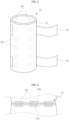
- FIG. 1 is a perspective view illustrating, a state in which a medical vibratory stimulation device is mounted on a body according to an embodiment of the present disclosure
- FIG. 2 is a perspective view illustrating a medical vibratory stimulation device according to an embodiment of the present disclosure
- FIG. 3 is a cross-sectional view illustrating a medical vibratory stimulation device according to an embodiment of the present disclosure
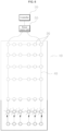
- FIG. 4 is an exploded view illustrating a medical vibratory stimulation device according to an embodiment of the present disclosure
- FIGS. 5 to 6 are exploded views illustrating a process of applying a vibratory stimulus to a target part of a body by a medical vibratory stimulation device according to an embodiment of the present disclosure.
- the medical vibratory stimulation device includes a mounting part 10, a plurality of vibration elements 20, and a controller 30.
- the mounting part 10 is a basic body of the present disclosure, and is mounted on a target part of a body.
- the target part of the body may be an upper body, a lower body, and a main body.
- the mounting part 10 may be formed in a shape corresponding to the upper body of the body, and may be mounted on the upper body of the body. Furthermore, the mounting part 10 may be formed in a shape corresponding to the lower body of the body, and may be mounted on the lower body of the body. Furthermore, the mounting part 10 may be formed in a shape corresponding to the main body of the body, and may be mounted on the main body of the body.
- the mounting part 10 may be formed of a flexible material to be mounted while pressing the target part of the body when being mounted on the target part of the body.
- the mounting part 10 has a diameter that is smaller than the target part of the body, and when being mounted on the target part of the body, the diameter increases and then decreases, and may be mounted while pressing the target part of the body.
- the flexible material may include at least one of polyurethane, nylon, spandex, and cotton.
- the mounting part 10 may include a cuff 12 and a fixing member 14.
- the cuff 12 may include an inner cover 12a and an outer cover 12b, and may accommodate the plurality of vibration elements 20.
- the plurality of vibration elements 20 may be accommodated between the inner cover 12a and the outer cover 12b of the cuff 12.
- the present disclosure is not limited thereto, and the plurality of vibration elements 20 may be provided on a contact surface of the inner cover 12a of the cuff 12, which contacts the target part of the body.
- the plurality of vibration elements 20 may be provided on a non-contact surface of the outer cover 12b of the cuff 12, which contacts the target part of the body.
- the cuff 12 may have a sleeve shape to surround the target part of the body.
- the fixing member 14 serves to fix the cuff 12 to the target part of the body while surrounding it.
- the fixing member 14 may be provided on a contact surface of the inner cover 12a of the cuff 12, which contacts the target part of the body, and may fix the cuff 12 to the target part of the body while the cuff 12 surrounds it.
- the fixing member 14 may include any one of a Velcro tape, a double-sided tape, a snap button, a hook, and a strap.
- the drawing illustrates an example, in which the fixing member 14 is a pair of Velcro tapes that surround the cuff 12 in a circumferential direction, the present disclosure is not limited thereto.
- the plurality of vibration elements 20 are disposed on the mounting part 10, and serve to apply vibratory stimuli to the target part of the body, respectively.
- vibration elements 20 For example, ultrasonic vibrators may be used as the vibration elements 20.
- the plurality of vibration elements 20 may be disposed in the mounting part 10 in a row direction and a column direction. That is, the plurality of vibration elements 20 may be disposed in a rectangular grid shape in the mounting part 10, as illustrated in FIG. 4 .
- the row direction may be a lengthwise direction of the mounting part 10 and a direction from a distal portion to a proximal portion of the target part of the body
- the column direction may be a circumferential direction of the mounting part 10, and hereinafter, only a row direction and a column direction will be referred to for unification of terms.
- the controller 30 controls the plurality of vibration elements 20 such that the plurality of vibration elements 20 sequentially apply vibratory stimuli from the distal portion to the proximal portion of the target part of the body.
- the controller 30 operates, among the plurality of vibration elements 20, the vibration elements 20 that are disposed in parallel in the first row from the distal portion of the target part of the body to control the vibratory stimuli to be applied to the target part of the body (see FIG. 5 ), and controls to operate the vibration elements 20 that are disposed in parallel in the second row (see FIG. 6 ) after stopping the vibration elements 20 that are disposed in parallel in the first row such that the vibratory stimuli that are generated for each row along the row direction are applied when the vibration elements 20 are sequentially moved from the distal portion of the target part of the body toward the proximal portion while the vibration elements 20 that are disposed in parallel in each row along the row direction are sequentially operated.
- controller 30 For example, a microcomputer or the like may be used as the controller 30.
- the medical vibratory stimulation device may further include an electric wire 40 and a power source unit 50.
- the electric wire 40 may electrically connect the plurality of the vibration elements 20 in the row direction and the column direction, for example, an electric wire line may be used as the electric wire 40.
- the power source unit 50 may provide electric power to the plurality of vibration elements 20 through the electric wire 40.
- the power source unit 50 may be a battery or a power supply device.
- the controller 30 operates, the vibration elements 20 that are disposed in parallel in the first row from the distal portion of the target part of the body to control the vibratory stimuli to be applied to the target part of the body (see FIG. 5 ), and controls to operate the vibration elements 20 that are disposed in parallel in the second row after stopping the vibration elements 20 that are disposed in parallel in the first row such that the vibratory stimuli that are generated for each row along the row direction are applied when the vibration elements 20 are sequentially moved from the distal portion of the target part of the body toward the proximal portion while the vibration elements 20 that are disposed in parallel in each row along the row direction are sequentially operated.
- the vibratory stimuli are sequentially applied from the distal portion to the proximal portion of the target part of the body to maximize an exercise effect of lymph fluid of the target part of the body and to induce extrinsic and intrinsic muscle contraction of the target part of the body, whereby the thickness of lymphoedema of the target part of the body may be decreased.
- FIGS. 7 to 8 are exploded views illustrating a process of applying a vibratory stimulus to a target part of a body by a medical vibratory stimulation device according to another embodiment of the present disclosure.
- a plurality of vibration elements 20 may be disposed to be misaligned with each other.
- the present embodiment may include a first group 20a having a plurality of vibration elements 20 that are disposed along the column direction, and a second group 20b having a plurality of vibration elements 20 that are adjacent to the first group 20a and are disposed along the column direction.
- the plurality of vibration elements 20 included in the first group 20a and the plurality of vibration elements 20 included in the second group 20b may be disposed to be misaligned with each other in the row direction, and the first group 20a and the second group 20b may be alternately disposed along the row direction.
- the controller 30 operates the vibration elements 20 included in the first group 20a, which are disposed in parallel in the first row, from the distal portion of the target part of the body to control the vibratory stimuli to be applied to the target part of the body (see FIG. 7 ), and then, controls the vibration elements 20 included in the second group 20b, which are disposed in parallel in the second row, to be operated after stopping the vibration elements 20 included in in the first group 20a, which are disposed in parallel in the first row (see FIG.
- the vibratory stimuli generated for each row along the row direction are sequentially applied toward the proximal portion from the distal portion of the target part of the body while the vibration elements 20 included in the first group 20a and the vibration elements 20 included in the second group 20b arranged in parallel for each row along the row direction are sequentially operated.
- the plurality of vibration elements 20 included in the first group 20a and the plurality of vibration elements 20 included in the second group 20b are disposed to be misaligned with each other in the row direction, vibratory stimuli that look as if they were moved in a diagonal direction may be applied to the target part of the body. Accordingly, the movement of the lymph fluid of the target part of the body in the diagonal direction may be assisted.
- the plurality of vibration elements 20 may be disposed in the mounting part 10 in a spiral direction.
- the plurality of vibration elements 20 may apply vibratory stimuli to the target part of the body in a spiral direction under the control of the controller 30. Accordingly, the movement of the lymph fluid of the target part of the body in the spiral direction may be assisted.
- the plurality of vibration elements 20 were allowed to transmit vibratory stimuli from the distal portion of the target part to the proximal portion of the body.
- the plurality of vibration elements 20 transmitted vibratory stimuli having a frequency of 30 Hz to 40 Hz and an amplitude of 4 mm to 5 mm displacement from the distal portion to the proximal portion of the target part of the body. Moreover, the plurality of vibration elements 20 transmitted vibratory stimuli to the target part of the body for about 10 to 20 minutes every day for about 5 weeks.
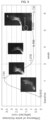
- FIG. 9 is a graph depicting a thickness of a target part of a body along a period, in which a vibratory stimulus is applied to a lower body target part of an experimental animal with lymphoedema by a medical vibratory stimulation device according to various embodiments of the present disclosure
- FIG. 10 is a graph illustrating that a frequency of lymph contraction increases due to vibratory stimuli at a lower body target part of an experimental animal with lymphoedema by a medical vibratory stimulation device according to various embodiments of the present disclosure.
- the target part of the body which was subjected to the vibratory stimuli by the plurality of vibration elements 20, as an exercise effect of the lymph fluid was maximized and the extrinsic and intrinsic muscle contraction was induced, the thickness of the lymphoedema decreased from about 3.7 mm to 0.7 m. Then, the target part of the body is the lower body.
- the frequency of the vibratory stimuli transmitted by the plurality of vibration elements 20 to the target part of the body was greater than 40 Hz or the amplitude displacement of the vibratory stimuli was greater than 5 mm
- an excessive impact was applied to the target part of the body, which was subjected to the vibratory stimuli
- the frequency of the vibratory stimuli transmitted by the plurality of vibration elements 20 to the target part of the body is less than 30 Hz or the amplitude displacement is less than 4 mm
- the vibratory stimuli were weakly transmitted to the target part of the body, which was subjected to the vibratory stimulus, whereby a lymphatic pumping effect and an effect of reducing the thickness of the lymphoedema area were decreased.
- the intensity of the frequencies transmitted by the plurality of vibration elements 20 to the target part of the body and the intensity of the vibratory stimuli are limited to the above values.
- the medical vibratory stimulation device may maximize the exercise effect by activating the muscles of the target part of the body by sequentially applying the vibratory stimuli from the distal portion to the proximal portion of the target part of the body, and may reduce the volume of the target part of the body with lymphoedema by inducing the lymphatic flow through the lymphatic pumping of the target part of the body.
Landscapes
- Health & Medical Sciences (AREA)
- Epidemiology (AREA)
- Pain & Pain Management (AREA)
- Physical Education & Sports Medicine (AREA)
- Rehabilitation Therapy (AREA)
- Life Sciences & Earth Sciences (AREA)
- Animal Behavior & Ethology (AREA)
- General Health & Medical Sciences (AREA)
- Public Health (AREA)
- Veterinary Medicine (AREA)
- Percussion Or Vibration Massage (AREA)
Abstract
Description
- Embodiments of the present disclosure described herein relate to a medical vibratory stimulation device.
- A composite lymphatic physical therapy, including a compression therapy, a manual drainage massage, and an exercise, is the most common lymphoedema treatment method, and applies physical pressures sequentially from a distal portion to a proximal portion of a target part of the body of a lymphoedema patient to move a lymph fluid accumulated in the target part of the body and thus reduce lymphoedema.
- The compression therapy provides gradient compression by using bandages, and the like based on the experience of highly trained physical therapists, and applies physical pressures from the distal portion to the proximal portion of the target part of the body through a manual massage to create lymphatic flow in the body.
- In the case of lymphoedema patients, it is important to receive complex lymphatic physical therapies periodically and consistently to improve the treatment prognosis, but the inconvenience of having to visit the hospital every time decreases the treatment compliance of lymphoedema patients, which has a negative effect on the treatment prognosis of lymphoedema.
- Accordingly, a medical vibratory stimulation device that may apply vibration stimuli to a target part of the body and thus, perform a gradient compression therapy in various places other than a specific place, such as a hospital, is necessary.
- However, the target part of the body of the conventional medical vibratory stimulation device is mainly the lower body, and thus has limitations in applying it to the upper body of the body.
- In addition, because the conventional medical vibratory stimulation device simultaneously transmits vibration stimuli to all areas of the target part of the body, the effect of decreasing a volume of the lymphoedema limb is not good.
- Embodiments of the present disclosure provide a medical vibratory stimulation device that sequentially applies vibration stimuli from a distal portion to a proximal portion of a target part of a body to activate muscles of the target part of the body to maximize an exercise effect and induce lymph flow through lymphatic vessel pumping of the target part of the body to reduce a volume of lymphoedema limbs of the target part of the body.
- The problems to be solved by the present disclosure are not limited to the problems mentioned above, and other problems that are not mentioned may be clearly understood by those skilled in the art from the description below.
- According to an embodiment, a medical vibratory stimulation device includes a mounting part mounted on a target part of a body, a plurality of vibration elements disposed in the mounting part, and configured to apply vibratory stimuli to the target part of the body, respectively, and a controller configured to control the plurality of vibration elements such that the plurality of vibration elements sequentially apply the vibratory stimuli from a distal portion to a proximal portion of the target part of the body.
- Furthermore, the plurality of vibration elements may be disposed along a row direction and a column direction of the mounting part.
- Furthermore, the medical vibratory stimulation device may include a first group having the plurality of vibration elements disposed along the column direction, and a second group being adjacent to the first group and having the plurality of vibration elements disposed along the column direction, the plurality of vibration elements included in the first group and the plurality of vibration elements included in the second group may be disposed to be misaligned with each other in the row direction, and the first group and the second group may be alternately disposed along the row direction.
- Furthermore, the plurality of vibration elements may be disposed in the mounting part along a spiral direction.
- Furthermore, the medical vibratory stimulation device may include an electric wire electrically connecting the plurality of vibration elements in a row direction and a column direction, and a power source unit configured to provide electric power to the plurality of vibration elements through the electric wire, and the controller may control the electric power provided to the vibration elements.
- Furthermore, the mounting part may include a cuff including an inner cover and an outer cover, and accommodating the plurality of vibration elements, and a fixing member configured to fix the cuff while surrounding the target part of the body.
- Furthermore, the fixing member may include any one of a Velcro tape, a double-sided tape, a snap button, a hook, or a strap.
- Furthermore, the mounting part may include at least one of polyurethane, nylon, spandex, and cotton.
- Other specific details of the present disclosure are included in the detailed description and drawings.
- The medical vibratory stimulation device according to an embodiment of the present disclosure may sequentially apply vibration stimuli from the distal portion to the proximal portion of the target part of the body to activate the muscles of the target part of the body to maximize an exercise effect and induce the lymph flow through lymphatic vessel pumping of the target part of the body to reduce the volume of lymphoedema limbs of the target part of the body.
- The effects of the present disclosure are not limited to the effects mentioned above, and other effects not mentioned will be clearly understood by those skilled in the art from the description below.
-
-
FIG. 1 is a perspective view illustrating, a state in which a medical vibratory stimulation device is mounted on a body according to an embodiment of the present disclosure. -
FIG. 2 is a perspective view illustrating a medical vibratory stimulation device according to an embodiment of the present disclosure. -
FIG. 3 is a cross-sectional view illustrating a medical vibratory stimulation device according to an embodiment of the present disclosure. -
FIG. 4 is an exploded view illustrating a medical vibratory stimulation device according to an embodiment of the present disclosure. -
FIGS. 5 to 6 are exploded views illustrating a process of applying a vibratory stimulus to a target part of a body by a medical vibratory stimulation device according to an embodiment of the present disclosure. -
FIGS. 7 to 8 are exploded views illustrating a process of applying a vibratory stimulus to a target part of a body by a medical vibratory stimulation device according to another embodiment of the present disclosure. -
FIG. 9 is a graph depicting a thickness of a target part of a body along a period, in which a vibratory stimulus is applied to a lower body target part of an experimental animal with lymphoedema by a medical vibratory stimulation device according to various embodiments of the present disclosure. -
FIG. 10 is a graph illustrating that a frequency of lymph contraction increases due to vibratory stimuli at a lower body target part of an experimental animal with lymphoedema by a medical vibratory stimulation device according to various embodiments of the present disclosure. - The advantages and features of the present disclosure, and the method of achieving them, will be clarified by referring to the embodiments described in detail below together with the attached drawings. However, the present disclosure is not limited to the embodiments disclosed below and may be implemented in various different forms, and these embodiments are provided only to ensure that the disclosure of the present disclosure is complete and to fully inform those skilled in the art, to which the present disclosure pertains, of the scope of the present disclosure, and the present disclosure is defined only by the scope of the claims.
- Unless otherwise defined, all terms (including technical and scientific terms) used in the specification may be used in a meaning that can be commonly understood by those skilled in the art, to which the present disclosure pertains. In addition, the terms defined in a commonly used dictionary shall not be ideally or excessively interpreted unless explicitly specifically defined.
- Before describing the present disclosure, in several embodiments, components having the same configuration will be representatively described in one embodiment by using the same reference numerals, and in other embodiments, a configuration that is different from that in one embodiment will be described.
- Hereinafter, embodiments of the present disclosure will be described in detail with reference to the accompanying drawings.
-
FIG. 1 is a perspective view illustrating, a state in which a medical vibratory stimulation device is mounted on a body according to an embodiment of the present disclosure,FIG. 2 is a perspective view illustrating a medical vibratory stimulation device according to an embodiment of the present disclosure,FIG. 3 is a cross-sectional view illustrating a medical vibratory stimulation device according to an embodiment of the present disclosure,FIG. 4 is an exploded view illustrating a medical vibratory stimulation device according to an embodiment of the present disclosure, andFIGS. 5 to 6 are exploded views illustrating a process of applying a vibratory stimulus to a target part of a body by a medical vibratory stimulation device according to an embodiment of the present disclosure. - As illustrated in
FIGS. 1 to 4 , the medical vibratory stimulation device according to an embodiment of the present disclosure includes amounting part 10, a plurality ofvibration elements 20, and acontroller 30. - The mounting
part 10 is a basic body of the present disclosure, and is mounted on a target part of a body. Here, the target part of the body may be an upper body, a lower body, and a main body. - Accordingly, the
mounting part 10 may be formed in a shape corresponding to the upper body of the body, and may be mounted on the upper body of the body. Furthermore, themounting part 10 may be formed in a shape corresponding to the lower body of the body, and may be mounted on the lower body of the body. Furthermore, themounting part 10 may be formed in a shape corresponding to the main body of the body, and may be mounted on the main body of the body. - The
mounting part 10 may be formed of a flexible material to be mounted while pressing the target part of the body when being mounted on the target part of the body. For example, themounting part 10 has a diameter that is smaller than the target part of the body, and when being mounted on the target part of the body, the diameter increases and then decreases, and may be mounted while pressing the target part of the body. Meanwhile, the flexible material may include at least one of polyurethane, nylon, spandex, and cotton. - The mounting
part 10 may include acuff 12 and afixing member 14. - The
cuff 12 may include aninner cover 12a and anouter cover 12b, and may accommodate the plurality ofvibration elements 20. Referring toFIG. 3 , the plurality ofvibration elements 20 may be accommodated between theinner cover 12a and theouter cover 12b of thecuff 12. However, the present disclosure is not limited thereto, and the plurality ofvibration elements 20 may be provided on a contact surface of theinner cover 12a of thecuff 12, which contacts the target part of the body. Furthermore, the plurality ofvibration elements 20 may be provided on a non-contact surface of theouter cover 12b of thecuff 12, which contacts the target part of the body. - The
cuff 12 may have a sleeve shape to surround the target part of the body. - The
fixing member 14 serves to fix thecuff 12 to the target part of the body while surrounding it. Specifically, thefixing member 14 may be provided on a contact surface of theinner cover 12a of thecuff 12, which contacts the target part of the body, and may fix thecuff 12 to the target part of the body while thecuff 12 surrounds it. For example, thefixing member 14 may include any one of a Velcro tape, a double-sided tape, a snap button, a hook, and a strap. However, although the drawing illustrates an example, in which thefixing member 14 is a pair of Velcro tapes that surround thecuff 12 in a circumferential direction, the present disclosure is not limited thereto. - The plurality of
vibration elements 20 are disposed on themounting part 10, and serve to apply vibratory stimuli to the target part of the body, respectively. For example, ultrasonic vibrators may be used as thevibration elements 20. - The plurality of
vibration elements 20 may be disposed in themounting part 10 in a row direction and a column direction. That is, the plurality ofvibration elements 20 may be disposed in a rectangular grid shape in themounting part 10, as illustrated inFIG. 4 . Here, the row direction may be a lengthwise direction of the mountingpart 10 and a direction from a distal portion to a proximal portion of the target part of the body, and the column direction may be a circumferential direction of the mountingpart 10, and hereinafter, only a row direction and a column direction will be referred to for unification of terms. - The
controller 30 controls the plurality ofvibration elements 20 such that the plurality ofvibration elements 20 sequentially apply vibratory stimuli from the distal portion to the proximal portion of the target part of the body. - Specifically, the
controller 30 operates, among the plurality ofvibration elements 20, thevibration elements 20 that are disposed in parallel in the first row from the distal portion of the target part of the body to control the vibratory stimuli to be applied to the target part of the body (seeFIG. 5 ), and controls to operate thevibration elements 20 that are disposed in parallel in the second row (seeFIG. 6 ) after stopping thevibration elements 20 that are disposed in parallel in the first row such that the vibratory stimuli that are generated for each row along the row direction are applied when thevibration elements 20 are sequentially moved from the distal portion of the target part of the body toward the proximal portion while thevibration elements 20 that are disposed in parallel in each row along the row direction are sequentially operated. - For example, a microcomputer or the like may be used as the
controller 30. - Meanwhile, the medical vibratory stimulation device according to an embodiment of the present disclosure may further include an
electric wire 40 and apower source unit 50. - The
electric wire 40 may electrically connect the plurality of thevibration elements 20 in the row direction and the column direction, for example, an electric wire line may be used as theelectric wire 40. - The
power source unit 50 may provide electric power to the plurality ofvibration elements 20 through theelectric wire 40. For example, thepower source unit 50 may be a battery or a power supply device. - According to the configuration, in the medical vibratory stimulation device according to an embodiment of the present disclosure, the
controller 30 operates, thevibration elements 20 that are disposed in parallel in the first row from the distal portion of the target part of the body to control the vibratory stimuli to be applied to the target part of the body (seeFIG. 5 ), and controls to operate thevibration elements 20 that are disposed in parallel in the second row after stopping thevibration elements 20 that are disposed in parallel in the first row such that the vibratory stimuli that are generated for each row along the row direction are applied when thevibration elements 20 are sequentially moved from the distal portion of the target part of the body toward the proximal portion while thevibration elements 20 that are disposed in parallel in each row along the row direction are sequentially operated. - Accordingly, the vibratory stimuli are sequentially applied from the distal portion to the proximal portion of the target part of the body to maximize an exercise effect of lymph fluid of the target part of the body and to induce extrinsic and intrinsic muscle contraction of the target part of the body, whereby the thickness of lymphoedema of the target part of the body may be decreased.
-
FIGS. 7 to 8 are exploded views illustrating a process of applying a vibratory stimulus to a target part of a body by a medical vibratory stimulation device according to another embodiment of the present disclosure. - As illustrated in
FIGS. 7 to 8 , unlike an embodiment, in the medical vibratory stimulation device according to another embodiment of the present disclosure, a plurality ofvibration elements 20 may be disposed to be misaligned with each other. - Specifically, the present embodiment may include a
first group 20a having a plurality ofvibration elements 20 that are disposed along the column direction, and asecond group 20b having a plurality ofvibration elements 20 that are adjacent to thefirst group 20a and are disposed along the column direction. - Here, the plurality of
vibration elements 20 included in thefirst group 20a and the plurality ofvibration elements 20 included in thesecond group 20b may be disposed to be misaligned with each other in the row direction, and thefirst group 20a and thesecond group 20b may be alternately disposed along the row direction. - In the embodiment, the
controller 30 operates thevibration elements 20 included in thefirst group 20a, which are disposed in parallel in the first row, from the distal portion of the target part of the body to control the vibratory stimuli to be applied to the target part of the body (seeFIG. 7 ), and then, controls thevibration elements 20 included in thesecond group 20b, which are disposed in parallel in the second row, to be operated after stopping thevibration elements 20 included in in thefirst group 20a, which are disposed in parallel in the first row (seeFIG. 8 ), and the vibratory stimuli generated for each row along the row direction are sequentially applied toward the proximal portion from the distal portion of the target part of the body while thevibration elements 20 included in thefirst group 20a and thevibration elements 20 included in thesecond group 20b arranged in parallel for each row along the row direction are sequentially operated. - Then, because the plurality of
vibration elements 20 included in thefirst group 20a and the plurality ofvibration elements 20 included in thesecond group 20b are disposed to be misaligned with each other in the row direction, vibratory stimuli that look as if they were moved in a diagonal direction may be applied to the target part of the body. Accordingly, the movement of the lymph fluid of the target part of the body in the diagonal direction may be assisted. - Meanwhile, the plurality of
vibration elements 20 may be disposed in the mountingpart 10 in a spiral direction. In this case, the plurality ofvibration elements 20 may apply vibratory stimuli to the target part of the body in a spiral direction under the control of thecontroller 30. Accordingly, the movement of the lymph fluid of the target part of the body in the spiral direction may be assisted. - By using the
controller 30 of the medical vibratory stimulation device according to various embodiments of the present disclosure, the plurality ofvibration elements 20 were allowed to transmit vibratory stimuli from the distal portion of the target part to the proximal portion of the body. - Then, the plurality of
vibration elements 20 transmitted vibratory stimuli having a frequency of 30 Hz to 40 Hz and an amplitude of 4 mm to 5 mm displacement from the distal portion to the proximal portion of the target part of the body. Moreover, the plurality ofvibration elements 20 transmitted vibratory stimuli to the target part of the body for about 10 to 20 minutes every day for about 5 weeks. -
FIG. 9 is a graph depicting a thickness of a target part of a body along a period, in which a vibratory stimulus is applied to a lower body target part of an experimental animal with lymphoedema by a medical vibratory stimulation device according to various embodiments of the present disclosure, andFIG. 10 is a graph illustrating that a frequency of lymph contraction increases due to vibratory stimuli at a lower body target part of an experimental animal with lymphoedema by a medical vibratory stimulation device according to various embodiments of the present disclosure. - As illustrated in
FIG. 9 , it could be identified that in the target part of the body, which was subjected to the vibratory stimuli by the plurality ofvibration elements 20, as an exercise effect of the lymph fluid was maximized and the extrinsic and intrinsic muscle contraction was induced, the thickness of the lymphoedema decreased from about 3.7 mm to 0.7 m. Then, the target part of the body is the lower body. - As illustrated in
FIG. 10 , a dynamic change in the actual lymph flow of the target part of the body, which was subjected to the vibratory stimuli by the plurality ofvibration elements 20, was measured, and the frequency of lymph contraction due to the vibration increased from 6 to 8 times per minute, and accordingly, an effect of increasing lymphatic drainage and reducing lymphoedema may be identified. - However, when the frequency of the vibratory stimuli transmitted by the plurality of
vibration elements 20 to the target part of the body was greater than 40 Hz or the amplitude displacement of the vibratory stimuli was greater than 5 mm, an excessive impact was applied to the target part of the body, which was subjected to the vibratory stimuli, and when the frequency of the vibratory stimuli transmitted by the plurality ofvibration elements 20 to the target part of the body is less than 30 Hz or the amplitude displacement is less than 4 mm, the vibratory stimuli were weakly transmitted to the target part of the body, which was subjected to the vibratory stimulus, whereby a lymphatic pumping effect and an effect of reducing the thickness of the lymphoedema area were decreased. - Accordingly, it is preferable that the intensity of the frequencies transmitted by the plurality of
vibration elements 20 to the target part of the body and the intensity of the vibratory stimuli are limited to the above values. - According to the present disclosure, the medical vibratory stimulation device according to various embodiments of the present disclosure may maximize the exercise effect by activating the muscles of the target part of the body by sequentially applying the vibratory stimuli from the distal portion to the proximal portion of the target part of the body, and may reduce the volume of the target part of the body with lymphoedema by inducing the lymphatic flow through the lymphatic pumping of the target part of the body.
- Although the present disclosure has been described above with reference to the attached drawings, it will be understood by those skilled in the art that the present disclosure may be implemented in other specific forms without changing the technical spirit or essential features thereof. Therefore, it should be understood that the present disclosure described above is illustrative in all respects and not restrictive.
[ INDUSTRIAL APPLICABILITY]
Claims (8)
- A medical vibratory stimulation device comprising:a mounting part mounted on a target part of a body;a plurality of vibration elements disposed in the mounting part, and configured to apply vibratory stimuli to the target part of the body, respectively; anda controller configured to control the plurality of vibration elements such that the plurality of vibration elements sequentially apply the vibratory stimuli from a distal portion to a proximal portion of the target part of the body.
- The medical vibratory stimulation device of claim 1, wherein the plurality of vibration elements are disposed along a row direction and a column direction of the mounting part.
- The medical vibratory stimulation device of claim 2, comprising:a first group having the plurality of vibration elements disposed along the column direction, and a second group being adjacent to the first group and having the plurality of vibration elements disposed along the column direction,wherein the plurality of vibration elements included in the first group and the plurality of vibration elements included in the second group are disposed to be misaligned with each other in the row direction, andwherein the first group and the second group are alternately disposed along the row direction.
- The medical vibratory stimulation device of claim 1, wherein the plurality of vibration elements are disposed in the mounting part along a spiral direction.
- The medical vibratory stimulation device of claim 1, further comprising:an electric wire electrically connecting the plurality of vibration elements in a row direction and a column direction; anda power source unit configured to provide electric power to the plurality of vibration elements through the electric wire,wherein the controller controls the electric power provided to the vibration elements.
- The medical vibratory stimulation device of claim 1, wherein the mounting part includes:a cuff including an inner cover and an outer cover, and accommodating the plurality of vibration elements; anda fixing member configured to fix the cuff while surrounding the target part of the body.
- The medical vibratory stimulation device of claim 6, wherein the fixing member includes any one of a Velcro tape, a double-sided tape, a snap button, a hook, or a strap.
- The medical vibratory stimulation device of claim 1, wherein the mounting part includes at least one of polyurethane, nylon, spandex, and cotton.
Applications Claiming Priority (2)
| Application Number | Priority Date | Filing Date | Title |
|---|---|---|---|
| KR1020220069405A KR102787172B1 (en) | 2022-06-08 | 2022-06-08 | Medical vibration stimulator |
| PCT/KR2023/003842 WO2023239023A1 (en) | 2022-06-08 | 2023-03-23 | Medical vibratory stimulation device |
Publications (2)
| Publication Number | Publication Date |
|---|---|
| EP4537803A1 true EP4537803A1 (en) | 2025-04-16 |
| EP4537803A4 EP4537803A4 (en) | 2025-09-17 |
Family
ID=89118531
Family Applications (1)
| Application Number | Title | Priority Date | Filing Date |
|---|---|---|---|
| EP23819962.4A Pending EP4537803A4 (en) | 2022-06-08 | 2023-03-23 | MEDICAL VIBRATION STIMULATION DEVICE |
Country Status (4)
| Country | Link |
|---|---|
| US (1) | US20250090415A1 (en) |
| EP (1) | EP4537803A4 (en) |
| KR (1) | KR102787172B1 (en) |
| WO (1) | WO2023239023A1 (en) |
Families Citing this family (1)
| Publication number | Priority date | Publication date | Assignee | Title |
|---|---|---|---|---|
| KR20230136512A (en) * | 2022-03-18 | 2023-09-26 | 주식회사 코어라인소프트 | Method and apparatus for determining level of airway region |
Family Cites Families (11)
| Publication number | Priority date | Publication date | Assignee | Title |
|---|---|---|---|---|
| WO2009136931A1 (en) * | 2008-05-08 | 2009-11-12 | Lotus Magnus, Llc. | Systems, devices, and methods for treating restless leg syndrome and periodic limb movement disorder |
| KR20090120200A (en) * | 2008-05-19 | 2009-11-24 | 한국과학기술원 | Somatosensory Stimulator |
| JP5739896B2 (en) * | 2009-11-05 | 2015-06-24 | コーニンクレッカ フィリップス エヌ ヴェ | Electrical muscle stimulation |
| CN102905669A (en) | 2010-05-26 | 2013-01-30 | 雅芒股份有限公司 | Massage device |
| KR101224480B1 (en) * | 2011-01-31 | 2013-01-21 | 전북대학교산학협력단 | Vibratory stimulation device for gips |
| KR102205421B1 (en) * | 2013-12-04 | 2021-01-20 | 삼성전자주식회사 | Wearable device and method for providing message of wearable device |
| JP2016016076A (en) * | 2014-07-08 | 2016-02-01 | 株式会社アイシス | Body rubbing device |
| US11491077B2 (en) * | 2016-06-06 | 2022-11-08 | Perumala Holdings, LLC | Vibration device |
| US11065174B2 (en) * | 2017-02-16 | 2021-07-20 | Rebecca Lach | Wearable interactive system and method of non-opioid and drug-free pain control |
| KR102027398B1 (en) * | 2017-09-19 | 2019-10-01 | 연세대학교 원주산학협력단 | Muscle stimulating wearable apparatus for directional stimulation and controlling method thereof |
| KR20210147578A (en) | 2020-05-29 | 2021-12-07 | (주)에스원바이오 | Lymphedema treatment device |
-
2022
- 2022-06-08 KR KR1020220069405A patent/KR102787172B1/en active Active
-
2023
- 2023-03-23 WO PCT/KR2023/003842 patent/WO2023239023A1/en not_active Ceased
- 2023-03-23 EP EP23819962.4A patent/EP4537803A4/en active Pending
-
2024
- 2024-11-27 US US18/961,944 patent/US20250090415A1/en active Pending
Also Published As
| Publication number | Publication date |
|---|---|
| US20250090415A1 (en) | 2025-03-20 |
| WO2023239023A1 (en) | 2023-12-14 |
| KR20230169507A (en) | 2023-12-18 |
| KR102787172B1 (en) | 2025-03-27 |
| EP4537803A4 (en) | 2025-09-17 |
Similar Documents
| Publication | Publication Date | Title |
|---|---|---|
| US11464969B2 (en) | Method and device for enhanced blood flow | |
| US20040254624A1 (en) | Electrical stimulator and garment electrode connection system | |
| US9271864B2 (en) | Orthosis for range of motion, muscular and neurologic rehabilitation of the lower extremities | |
| US20150257970A1 (en) | Device and method for reducing pain | |
| US8755894B2 (en) | Method and device for enhanced blood flow | |
| CN113101518B (en) | Acupoint stimulation device and acupoint stimulation method using same | |
| WO2018187241A1 (en) | Systems, methods and devices for peripheral neuromodulation for treating diseases related to overactive bladder | |
| US4552132A (en) | Pulsating hydrotherapy system | |
| JP2017524396A (en) | System and method for peripheral nerve stimulation for treating tremor | |
| EP3878506A1 (en) | Medical therapy arrangement | |
| JP2017524396A5 (en) | ||
| WO2009136931A1 (en) | Systems, devices, and methods for treating restless leg syndrome and periodic limb movement disorder | |
| US20250090415A1 (en) | Medical vibratory stimulation device | |
| US20250134761A1 (en) | Muscle passive haptic rehabilitation systems and methods for treating neurological dysfunctions | |
| KR20120001366U (en) | Waist band for composite physical theraphy | |
| KR20240169621A (en) | Treatment system and method by electrophysiological stimulation | |
| US20260124101A1 (en) | Modular therapeutic device and methods of use thereof | |
| US20130138143A1 (en) | Acupressure device with a plurality of individually-controlled applicators having protrusions extending therefrom | |
| KR200447803Y1 (en) | Limb compression air massager | |
| US20250099746A1 (en) | Method and apparatus for noninvasive inhibition of deep vein thrombosis | |
| KR102196663B1 (en) | Apparatus using high frequency and mechanical stimulas for decreaing fat | |
| CN117018445A (en) | Multifunctional myoelectricity biofeedback-based treatment device and control method | |
| CN209771106U (en) | Medical treatment device | |
| RU103733U1 (en) | INSTALLATION FOR DIAGNOSIS AND TREATMENT OF THE PATIENT | |
| KR200427531Y1 (en) | Combined low frequency physiotherapy machine with acupoints |
Legal Events
| Date | Code | Title | Description |
|---|---|---|---|
| STAA | Information on the status of an ep patent application or granted ep patent |
Free format text: STATUS: THE INTERNATIONAL PUBLICATION HAS BEEN MADE |
|
| PUAI | Public reference made under article 153(3) epc to a published international application that has entered the european phase |
Free format text: ORIGINAL CODE: 0009012 |
|
| STAA | Information on the status of an ep patent application or granted ep patent |
Free format text: STATUS: REQUEST FOR EXAMINATION WAS MADE |
|
| 17P | Request for examination filed |
Effective date: 20241209 |
|
| AK | Designated contracting states |
Kind code of ref document: A1 Designated state(s): AL AT BE BG CH CY CZ DE DK EE ES FI FR GB GR HR HU IE IS IT LI LT LU LV MC ME MK MT NL NO PL PT RO RS SE SI SK SM TR |
|
| A4 | Supplementary search report drawn up and despatched |
Effective date: 20250819 |
|
| DAV | Request for validation of the european patent (deleted) | ||
| DAX | Request for extension of the european patent (deleted) | ||
| RIC1 | Information provided on ipc code assigned before grant |
Ipc: A61H 23/02 20060101AFI20250812BHEP |
|
| GRAP | Despatch of communication of intention to grant a patent |
Free format text: ORIGINAL CODE: EPIDOSNIGR1 |
|
| STAA | Information on the status of an ep patent application or granted ep patent |
Free format text: STATUS: GRANT OF PATENT IS INTENDED |