EP4537764A1 - Ultrasonic probe and flexible printed circuit board - Google Patents
Ultrasonic probe and flexible printed circuit board Download PDFInfo
- Publication number
- EP4537764A1 EP4537764A1 EP24153591.3A EP24153591A EP4537764A1 EP 4537764 A1 EP4537764 A1 EP 4537764A1 EP 24153591 A EP24153591 A EP 24153591A EP 4537764 A1 EP4537764 A1 EP 4537764A1
- Authority
- EP
- European Patent Office
- Prior art keywords
- connection part
- circuit board
- printed circuit
- ultrasonic
- probe
- Prior art date
- Legal status (The legal status is an assumption and is not a legal conclusion. Google has not performed a legal analysis and makes no representation as to the accuracy of the status listed.)
- Granted
Links
Images






Classifications
-
- A—HUMAN NECESSITIES
- A61—MEDICAL OR VETERINARY SCIENCE; HYGIENE
- A61B—DIAGNOSIS; SURGERY; IDENTIFICATION
- A61B8/00—Diagnosis using ultrasonic, sonic or infrasonic waves
- A61B8/56—Details of data transmission or power supply
-
- G—PHYSICS
- G01—MEASURING; TESTING
- G01S—RADIO DIRECTION-FINDING; RADIO NAVIGATION; DETERMINING DISTANCE OR VELOCITY BY USE OF RADIO WAVES; LOCATING OR PRESENCE-DETECTING BY USE OF THE REFLECTION OR RERADIATION OF RADIO WAVES; ANALOGOUS ARRANGEMENTS USING OTHER WAVES
- G01S7/00—Details of systems according to groups G01S13/00, G01S15/00, G01S17/00
- G01S7/52—Details of systems according to groups G01S13/00, G01S15/00, G01S17/00 of systems according to group G01S15/00
- G01S7/52017—Details of systems according to groups G01S13/00, G01S15/00, G01S17/00 of systems according to group G01S15/00 particularly adapted to short-range imaging
- G01S7/52079—Constructional features
- G01S7/52082—Constructional features involving a modular construction, e.g. a computer with short range imaging equipment
-
- A—HUMAN NECESSITIES
- A61—MEDICAL OR VETERINARY SCIENCE; HYGIENE
- A61B—DIAGNOSIS; SURGERY; IDENTIFICATION
- A61B8/00—Diagnosis using ultrasonic, sonic or infrasonic waves
- A61B8/44—Constructional features of the ultrasonic, sonic or infrasonic diagnostic device
- A61B8/4444—Constructional features of the ultrasonic, sonic or infrasonic diagnostic device related to the probe
-
- A—HUMAN NECESSITIES
- A61—MEDICAL OR VETERINARY SCIENCE; HYGIENE
- A61B—DIAGNOSIS; SURGERY; IDENTIFICATION
- A61B8/00—Diagnosis using ultrasonic, sonic or infrasonic waves
- A61B8/44—Constructional features of the ultrasonic, sonic or infrasonic diagnostic device
- A61B8/4444—Constructional features of the ultrasonic, sonic or infrasonic diagnostic device related to the probe
- A61B8/4461—Features of the scanning mechanism, e.g. for moving the transducer within the housing of the probe
- A61B8/4466—Features of the scanning mechanism, e.g. for moving the transducer within the housing of the probe involving deflection of the probe
-
- A—HUMAN NECESSITIES
- A61—MEDICAL OR VETERINARY SCIENCE; HYGIENE
- A61B—DIAGNOSIS; SURGERY; IDENTIFICATION
- A61B8/00—Diagnosis using ultrasonic, sonic or infrasonic waves
- A61B8/44—Constructional features of the ultrasonic, sonic or infrasonic diagnostic device
- A61B8/4483—Constructional features of the ultrasonic, sonic or infrasonic diagnostic device characterised by features of the ultrasound transducer
- A61B8/4488—Constructional features of the ultrasonic, sonic or infrasonic diagnostic device characterised by features of the ultrasound transducer the transducer being a phased array
-
- G—PHYSICS
- G01—MEASURING; TESTING
- G01S—RADIO DIRECTION-FINDING; RADIO NAVIGATION; DETERMINING DISTANCE OR VELOCITY BY USE OF RADIO WAVES; LOCATING OR PRESENCE-DETECTING BY USE OF THE REFLECTION OR RERADIATION OF RADIO WAVES; ANALOGOUS ARRANGEMENTS USING OTHER WAVES
- G01S7/00—Details of systems according to groups G01S13/00, G01S15/00, G01S17/00
- G01S7/52—Details of systems according to groups G01S13/00, G01S15/00, G01S17/00 of systems according to group G01S15/00
- G01S7/52017—Details of systems according to groups G01S13/00, G01S15/00, G01S17/00 of systems according to group G01S15/00 particularly adapted to short-range imaging
- G01S7/52079—Constructional features
- G01S7/52084—Constructional features related to particular user interfaces
-
- G—PHYSICS
- G10—MUSICAL INSTRUMENTS; ACOUSTICS
- G10K—SOUND-PRODUCING DEVICES; METHODS OR DEVICES FOR PROTECTING AGAINST, OR FOR DAMPING, NOISE OR OTHER ACOUSTIC WAVES IN GENERAL; ACOUSTICS NOT OTHERWISE PROVIDED FOR
- G10K11/00—Methods or devices for transmitting, conducting or directing sound in general; Methods or devices for protecting against, or for damping, noise or other acoustic waves in general
- G10K11/18—Methods or devices for transmitting, conducting or directing sound
- G10K11/26—Sound-focusing or directing, e.g. scanning
- G10K11/35—Sound-focusing or directing, e.g. scanning using mechanical steering of transducers or their beams
- G10K11/352—Sound-focusing or directing, e.g. scanning using mechanical steering of transducers or their beams by moving the transducer
- G10K11/355—Arcuate movement
-
- H—ELECTRICITY
- H05—ELECTRIC TECHNIQUES NOT OTHERWISE PROVIDED FOR
- H05K—PRINTED CIRCUITS; CASINGS OR CONSTRUCTIONAL DETAILS OF ELECTRIC APPARATUS; MANUFACTURE OF ASSEMBLAGES OF ELECTRICAL COMPONENTS
- H05K1/00—Printed circuits
- H05K1/02—Details
- H05K1/14—Structural association of two or more printed circuits
- H05K1/147—Structural association of two or more printed circuits at least one of the printed circuits being bent or folded, e.g. by using a flexible printed circuit
-
- A—HUMAN NECESSITIES
- A61—MEDICAL OR VETERINARY SCIENCE; HYGIENE
- A61B—DIAGNOSIS; SURGERY; IDENTIFICATION
- A61B2562/00—Details of sensors; Constructional details of sensor housings or probes; Accessories for sensors
- A61B2562/16—Details of sensor housings or probes; Details of structural supports for sensors
- A61B2562/166—Details of sensor housings or probes; Details of structural supports for sensors the sensor is mounted on a specially adapted printed circuit board
-
- A—HUMAN NECESSITIES
- A61—MEDICAL OR VETERINARY SCIENCE; HYGIENE
- A61B—DIAGNOSIS; SURGERY; IDENTIFICATION
- A61B8/00—Diagnosis using ultrasonic, sonic or infrasonic waves
- A61B8/44—Constructional features of the ultrasonic, sonic or infrasonic diagnostic device
- A61B8/4405—Device being mounted on a trolley
-
- A—HUMAN NECESSITIES
- A61—MEDICAL OR VETERINARY SCIENCE; HYGIENE
- A61B—DIAGNOSIS; SURGERY; IDENTIFICATION
- A61B8/00—Diagnosis using ultrasonic, sonic or infrasonic waves
- A61B8/44—Constructional features of the ultrasonic, sonic or infrasonic diagnostic device
- A61B8/4427—Device being portable or laptop-like
-
- A—HUMAN NECESSITIES
- A61—MEDICAL OR VETERINARY SCIENCE; HYGIENE
- A61B—DIAGNOSIS; SURGERY; IDENTIFICATION
- A61B8/00—Diagnosis using ultrasonic, sonic or infrasonic waves
- A61B8/44—Constructional features of the ultrasonic, sonic or infrasonic diagnostic device
- A61B8/4444—Constructional features of the ultrasonic, sonic or infrasonic diagnostic device related to the probe
- A61B8/4472—Wireless probes
Definitions
- various medical imaging devices have been widely used to image and obtain information about biological tissues of a human body for the purpose of early diagnosis of various diseases or surgery.
- Representative examples of such medical imaging devices may include ultrasonic imaging devices, CT devices, and MRI devices.
- the first connection part may be folded twice or more and overlapped with the second connection part.
- the first connection part and the second connection part may be completely overlapped with each other.
- FIG. 1A illustrates a control block diagram of the ultrasonic imaging system 100 in a case in which the probe 20 is a wired probe or a hybrid probe.
- the probe 20 may include a plurality of transducers.
- the plurality of transducers may transmit an ultrasonic signal to an object 10 in response to a transmission signal applied from a transmission module 113.
- the plurality of transducers may form a received signal by receiving the ultrasonic signal (echo signal) reflected from the object 10.
- the probe 20 may also be implemented integrally with the ultrasonic imaging device 40, or may be implemented as a separate type connected to the ultrasonic imaging device 40 by wire.
- the ultrasonic imaging device 40 may be connected to the one or more probes 20 depending on the implementation type.
- the probe 20 may be implemented as a two-dimensional probe.
- the plurality of transducers included in the probe 20 may be arranged in two dimensions to form a two-dimensional transducer array.
- the two-dimensional transducer array may have a form in which a plurality of sub-arrays including the plurality of transducers arranged in a first direction is arranged in a second direction different from the first direction.
- a processor 120 controls the transmission module 113 to form a transmission signal to be applied to each of a transducers 115 in consideration of positions and focal points of the plurality of transducers included in the probe 20.
- the processor 120 may calculate a time delay value for digital beamforming for each sub-array for each of the plurality of sub-arrays included in the two-dimensional transducer array.
- the processor 120 may also calculate a time delay value for analog beamforming for each of the transducers included in one of the plurality of sub-arrays.
- the processor 120 may control the analog beamformer and the digital beamformer to form a transmission signal to be applied to each of the plurality of transducers depending on the time delay values for analog beamforming and the time delay values for digital beamforming.
- the processor 120 may also control the analog beamformer to sum up the signals received from the plurality of transducers for each sub-array depending on the time delay values for analog beamforming.
- the processor 120 may also control the ultrasonic transmission/reception module 110 to convert the summed signal for each sub-array to analog to digital.
- the processor 120 may also control the digital beamformer to generate ultrasonic data by summing the digitally converted signals depending on the time delay values for digital beamforming.
- the image processor 130 generates an ultrasonic image using the generated ultrasonic data.
- the display 140 may display the generated ultrasonic image and a variety of information processed by the ultrasonic imaging device 40 and/or the probe 20.
- the probe 20 and/or the ultrasonic imaging device 40 may include the one or more displays 140 depending on the implementation type.
- the display 140 may include a touch panel or a touch screen.
- the processor 120 may control the overall operation of the ultrasonic imaging device 40 and signal flow between internal components of the ultrasonic imaging device 40.
- the processor 120 may perform or control various operations or functions of the ultrasonic imaging device 40 by executing programs or instructions stored in a memory 150.
- the processor 120 may also control an operation of the ultrasonic imaging device 40 by receiving a control signal from the input interface 170 or an external device.
- the ultrasonic imaging device 40 may include a communication module 160, and may be connected to an external device (e.g., the probe 20, a server, medical device, portable device (a smart phone, tablet PC, wearable device, etc.)) through the communication module 160.
- an external device e.g., the probe 20, a server, medical device, portable device (a smart phone, tablet PC, wearable device, etc.)
- the communication module 160 may include one or more components that enable communication with the external device, and may include, for example, at least one of a short-range communication module, a wired communication module, and a wireless communication module.
- the communication module 160 may receive a control signal and data from the external device, and may transmit the received control signal to the processor 120 to enable the processor 120 to control the ultrasonic imaging device 40 depending on the received control signal.
- the processor 120 may transmit a control signal to the external device through the communication module 160 to control the external device depending on the control signal of the processor.
- the external device may process data within the external device depending on the control signal of the processor received through the communication module.
- a program capable of controlling the ultrasonic imaging device 40 may be installed in the external device, and this program may include instructions for performing some or all of the operations of the processor 120.
- the program may be pre-installed on the external device, or a user of the external device may download and install the program from a server providing an application.
- the server providing the application may include a recording medium in which the program is stored.
- the memory 150 may store various data or programs for driving and controlling the ultrasonic imaging device 40, inputted and outputted ultrasonic data, ultrasonic images, etc.
- the input interface 170 may receive user input for controlling the ultrasonic imaging device 40.
- the user input may include, but is not limited to, input of manipulating a button, a keypad, a mouse, a trackball, a jog switch, a knob, and the like, input of touching a touch pad or touch screen, voice input, motion input, biometric information input (e.g., iris recognition, fingerprint recognition, etc.), and the like.
- FIG. 1B illustrates a control block diagram of the ultrasonic imaging system 100 in the case in which the probe 20 is a wireless probe or a hybrid probe.
- the ultrasonic imaging device 40 illustrated in FIG. 1B may be replaced with the ultrasonic imaging device 40 described with reference to FIG. 1A .
- the probe 20 illustrated in FIG. 1A may be replaced with the probe 20 to be described with reference to FIG. 1B .
- the probe 20 may include the transmission module 113, a battery 114, the transducer 115, a charging module 116, the reception module 117, a processor 118, and a communication module 119.
- FIG. 1B illustrates that probe 20 includes both the transmission module 113 and the reception module 117, depending on the implementation type, the probe 20 may include only part of a configuration of the transmission module 113 and the reception module 117, and the part of the configuration of the transmission module 113 and the reception module 117 may be included in the ultrasonic imaging device 40.
- the probe 20 may further include the image processor 130.
- the transducer 115 may include a plurality of transducers.
- the plurality of transducers may transmit an ultrasonic signal to the object 10 in response to a transmission signal applied from the transmission module 113.
- the plurality of transducers may receive the ultrasonic signal reflected from the object 10 to form a reception signal.
- the charging module 116 may charge the battery 114.
- the charging module 116 may receive power from the outside.
- the charging module 116 may receive power wirelessly. However, the disclosure is not limited thereto, and the charging module 116 may receive power by wire.
- the charging module 116 may transfer the received power to the battery 114.
- the processor 118 controls the transmission module 113 to form a transmission signal to be applied to each of the plurality of transducers in consideration of the positions and focal points of the plurality of transducers.
- the processor 118 controls the reception module 117 to generate ultrasonic data by converting reception signals received from the transducer 115 to analog to digital and summing the digitally converted reception signals in consideration of the positions and focal points of the plurality of transducers.
- the probe 20 may generate an ultrasonic image using the generated ultrasonic data.
- the processor 118 may calculate a time delay value for digital beamforming for each sub-array for each of the plurality of sub-arrays included in the two-dimensional transducer array.
- the processor 118 may also calculate a time delay value for analog beamforming for each of the transducers included in one of the plurality of sub-arrays.
- the processor 118 may control the analog beamformer and the digital beamformer to form a transmission signal to be applied to each of the plurality of transducers depending on the time delay values for analog beamforming and the time delay values for digital beamforming.
- the processor 118 may also control the analog beamformer to sum up the signals received from the plurality of transducers for each sub-array depending on the time delay values for analog beamforming.
- the processor 118 may also control the ultrasonic transmission/reception module 110 to convert the summed signal for each sub-array to analog to digital.
- the processor 118 may also control the digital beamformer to generate ultrasonic data by summing the digitally converted signals depending on the time delay values for digital beamforming.
- the processor 118 may control the overall operation of the probe 20 and the signal flow between the internal components of the probe 20.
- the processor 118 may perform or control the various operations or functions of the probe 20 by executing programs or instructions stored in a memory 111.
- the processor 118 may also control the operation of the probe 20 by receiving the control signal from the input interface 170 of the probe 20 or an external device (e.g., the ultrasonic imaging device 40).
- the communication module 119 may wirelessly transmit the generated ultrasonic data or ultrasonic images to the ultrasonic imaging device 40 through a wireless network.
- the communication module 119 may also receive control signals and data from the ultrasonic imaging device 40.
- the ultrasonic imaging device 40 may receive the ultrasonic data or ultrasonic images from the probe 20.
- the probe 20 may transmit ultrasonic data and/or the ultrasonic images generated by the image processor 130 to the ultrasonic imaging device 40.
- the probe 20 may transmit ultrasonic data to the ultrasonic imaging device 40.
- the ultrasonic data may include ultrasonic raw data, and the ultrasonic image may refer to ultrasonic image data.
- the ultrasonic imaging device 40 may include the processor 120, the image processor 130, the display 140, the memory 150, the communication module 160, and the input interface 170.
- the image processor 130 generates an ultrasonic image using ultrasonic data received from the probe 20.
- the display 140 may display an ultrasonic image received from the probe 20, an ultrasonic image generated by processing ultrasonic data received from the probe 20, and a variety of information processed by the ultrasonic imaging system 100.
- the ultrasonic imaging device 40 may include the one or more displays 140 depending on the implementation type.
- the display 140 may include a touch panel or a touch screen.
- the processor 120 may control the overall operation of the ultrasonic imaging device 40 and the signal flow between the internal components of the ultrasonic imaging device 40.
- the processor 120 may perform or control the various operations or functions of the ultrasonic imaging device 40 by executing the programs or applications stored in a memory 150.
- the processor 120 may also control the operation of the ultrasonic imaging device 40 by receiving the control signal from the input interface 170 or an external device.
- the ultrasonic imaging device 40 may include the communication module 160, and may be connected to an external device (e.g., the probe 20, a server, medical device, portable device (a smart phone, tablet PC, wearable device, etc.)) through the communication module 160.
- an external device e.g., the probe 20, a server, medical device, portable device (a smart phone, tablet PC, wearable device, etc.)
- the communication module 160 may include one or more components that enable communication with the external device, and may include, for example, at least one of a short-range communication module, a wired communication module, and a wireless communication module.
- the communication module 160 of the ultrasonic imaging device 40 and the communication module 119 of the probe 20 may communicate using a network or a short-range wireless communication method.
- the communication module 160 of the ultrasonic imaging device 40 and the communication module 119 of the probe 20 may communicate using any one of wireless LAN, Wi-Fi, Bluetooth, ZigBee, Wi-Fi Direct (WFD), Infrared Data Association (IrDA), Bluetooth Low Energy (BLE), Near Field Communication (NFC), Wireless Broadband Internet (WiBro), World Interoperability for Microwave Access (WiMAX), Shared Wireless Access Protocol (SWAP), Wireless Gigabit Alliance (WiGig), RF communication, a wireless data communication method including 60GHz millimeter wave (mm wave) short-range communication, etc.
- the communication module 160 of the ultrasonic imaging device 40 and the communication module 119 of the probe 20 may include at least one of a wireless LAN communication module, a Wi-Fi communication module, a Bluetooth communication module, a ZigBee communication module, a Wi-Fi Direct (WFD) communication module, an Infrared Data Association (IrDA) communication module, a Bluetooth Low Energy (BLE) communication module, a Near Field Communication (NFC) module, a Wireless Broadband Internet (WiBro) communication module, a World Interoperability for Microwave Access (WiMAX) communication module, a Shared Wireless Access Protocol (SWAP) communication module, a Wireless Gigabit Alliance (WiGig) communication module, a RF communication module, and a 60GHz millimeter wave (mm wave) short-range communication module.
- a wireless LAN communication module a Wi-Fi communication module
- a Bluetooth communication module a ZigBee communication module
- Wi-Fi Direct (WFD) communication module an Infrared Data Association (IrDA
- the probe 20 may transmit device information (e.g., ID information) of the probe 20 using a first communication method (e.g., BLE), may be wirelessly paired with the ultrasonic imaging device 40, and may transmit ultrasonic data and/or ultrasonic images to the paired ultrasonic imaging device 40.
- a first communication method e.g., BLE
- the device information of the probe 20 may include a variety of information related to a serial number, model name, and battery state of the probe 20.
- the ultrasonic imaging device 40 may receive the device information (e.g., ID information) of the probe 20 from the probe 20 using the first communication method (e.g., BLE), may be wirelessly paired with the probe 20, may transmit an activation signal to the paired probe 20, and may receive the ultrasonic data and/or ultrasonic images from the probe 20.
- the activation signal may include a signal for controlling the operation of the probe 20.
- the probe 20 may transmit the device information (e.g., ID information) of the probe 20 using the first communication method (e.g., BLE), may be wirelessly paired with the ultrasonic imaging device 40, and may transmit the ultrasonic data and/or ultrasonic images to the ultrasonic imaging device 40 paired by the first communication method using a second communication method (e.g., 60 GHz millimeter wave and Wi-Fi).
- the first communication method e.g., BLE
- a second communication method e.g. 60 GHz millimeter wave and Wi-Fi
- the ultrasonic imaging device 40 may receive the device information (e.g., ID information) of the probe 20 from the probe 20 using the first communication method (e.g., BLE), may be wirelessly paired with the probe 20, may transmit the activation signal to the paired probe 20, and may receive the ultrasonic data and/or ultrasonic images from the probe 20 using the second communication method (e.g., 60 GHz millimeter wave and Wi-Fi).
- the first communication method e.g., BLE
- the first communication method e.g., BLE
- the first communication method e.g., BLE
- the second communication method e.g. 60 GHz millimeter wave and Wi-Fi
- the first communication method used to pair the probe 20 and the ultrasonic imaging device 40 with each other may have a lower frequency band than the frequency band of the second communication method used by the probe 20 to transmit the ultrasonic data and/or ultrasonic images to the ultrasonic imaging device 40.
- the display 140 of the ultrasonic imaging device 40 may display Uls indicating device information of the probe 20.
- the display 140 may display Uls, which indicate identification information of the wireless ultrasonic probe 20, a pairing method indicating a pairing method with the probe 20, a data communication state between the probe 20 and the ultrasonic imaging device 40, a method of performing data communication with the ultrasonic imaging device 40, and the battery state of the probe 20.
- the display 140 of the probe 20 may display Uls indicating the device information of the probe 20.
- the display 140 may display Uls, which indicate the identification information of the wireless ultrasonic probe 20, the pairing method indicating the pairing method with the probe 20, the data communication state between the probe 20 and the ultrasonic imaging device 40, the method of performing data communication with the ultrasonic imaging device 40, and the battery state of the probe 20.
- the communication module 160 may receive a control signal and data from an external device and transmit the received control signal to the processor 120 so that the processor 120 controls the ultrasonic imaging device 40 depending on the received control signal.
- the processor 120 may transmit a control signal to the external device through the communication module 160 to control the external device depending on the control signal of the processor 120.
- the external device may process data of the external device depending on the control signal of the processor 120 received through the communication module 160.
- a program capable of controlling the ultrasonic imaging device 40 may be installed in the external device, and this program may include instructions for performing part or all of the operations of the processor 120.
- the program may be pre-installed on the external device, or the user of the external device may download and install the program from the server providing the application.
- the server providing the application may include the recording medium on which the program is stored.
- the memory 150 may store various data or programs for driving and controlling the ultrasonic imaging device 40, inputted and outputted ultrasonic data, ultrasonic images, etc.
- FIGS. 2A , 2B , 2C , and 2D An example of the ultrasonic imaging system 100 according to an embodiment of the disclosure will be described later through FIGS. 2A , 2B , 2C , and 2D .
- the transducer array 115 may be connected to a rotation shaft d and rotated around the rotation shaft d by a motor 210.
- the ultrasonic signal emitted in two dimensions by the transducer array 115 may obtain a three-dimensional ultrasonic image as the transducer array 115 rotates.
- loads are applied to the signal connector as the transducer array 115 rotates, and various types of signal connectors may be used to withstand the loads.
- a coaxial cable may be used as a signal connector, and as illustrated in FIG. 4B , a flexible printed circuit board (FPCB) 230 may also be used.
- FPCB flexible printed circuit board
- the signal connector may be used in various ways.
- the coaxial cable In the case of using the coaxial cable as a signal connector, the coaxial cable easily distributes the loads so that durability may increase, but manufacturing costs increase so that manufacturing may not be easy. In addition, a space occupied by the coaxial cable may increase due to the increase in signal channels.
- the manufacturing cost is reduced so that the manufacturing may be easy and a space occupied by the FPCB may be small compared to the coaxial cable, but the durability may be reduced because it is difficult to distribute the loads.
- the FPCB occupies less space compared to the coaxial cable, as the number of signal channels continues to increase, the signal channels occupy a lot of space in the ultrasonic probe 20, which may increase the volume of the product.
- a structure of the FPCB is disclosed to solve problems in space utilization that occur when the FPCB is used as a signal connector.
- the loads resulting from the rotation of the transducer array 115 may be better distributed, thereby improving durability.
- the loads applied to the flexible printed circuit board 230 may be distributed.
- FIGS. 6A to 6C are views for explaining a new structure of the flexible printed circuit board according to an embodiment
- FIG. 7 is a view illustrating the ultrasonic probe into which the flexible printed circuit board is inserted.
- the ultrasonic probe 20 may include the transducer array 115 connected to the rotation shaft d, and the motor 210 provided to rotate the transducer around the rotation shaft d.
- the ultrasonic probe 20 may also include a printed circuit board 220 provided to output a driving signal for driving the transducer array 115 and the flexible printed circuit board 230 as a signal connector electrically connected to the printed circuit board 220 to transmit the driving signal to the transducer array 115.
- the flexible printed circuit board 230 may include an array terminal 231 electrically connected to the transducer array 115, a first terminal 232 electrically connected to one portion of the printed circuit board, a first connection part 233 connecting the array terminal 231 and the first terminal 232, a second terminal 234 electrically connected to the other portion of the printed circuit board, and a second connection part 235 connecting the array terminal 231 and the second terminal 234.
- the array terminal 231 may transmit or receive signals to or from the transducer by being electrically connected to the transducer array 115.
- the array terminal 231 may be separated into t two or more strands and each connected to the printed circuit board.
- the disclosure exemplifies two strands, but is not limited thereto, and the array terminal may be separated into two or more strands.
- the first connection part 233 may connect the first terminal 232 and the array terminal 231
- the second connection part 235 may connect the second terminal 234 and the array terminal 231.
- a first strand including the first connection part 233 and the first terminal 232 may be folded at least twice to be overlapped with a second strand including the second connection part 235 and the second terminal 234.
- the first strand may be folded once as illustrated in FIG. 6B , and folded once more as illustrated in FIG. 6C to be overlapped with the second strand.
- first terminal 232 and the second terminal 234 are not overlapped with each other, and the first connection part 233 and the second connection part 235 may be overlapped with each other.
- first connection part 233 is folded twice as illustrated in FIG. 6
- the disclosure is not limited thereto, and the first connection part 233 may be overlapped with the second connection part 235 by being folded twice or more.
- first connection part 233 and the second connection part 235 may be completely overlapped with each other depending on a structural design.
- first connection part 233 which is a connection part to be folded, longer, when the first connection part 233 is folded and overlapped with the second connection part 235, the first terminal 232 and the second terminal 234 may be positioned on the same line.
- the overlapped portion may be wound around the rotation shaft d, as illustrated in FIG. 5B .
- a portion where the first connection part 233 and the second connection part 235 are overlapped with each other may be wound around the rotation shaft d.
- the space occupied by the flexible printed circuit board 230 in the ultrasonic probe 20 may be reduced, thereby preventing a size of the ultrasonic probe 20 from increasing.
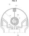
- FIG. 8 is a view of the ultrasonic probe according to an embodiment viewed from a side
- FIG. 9 is a view of the ultrasonic probe according to an embodiment viewed from the front.
- the ultrasonic array may is rotated around the rotation shaft d by the motor 210, and the flexible printed circuit board 230 may be wound around the rotation shaft d in the form of a clockwork.
- a rotation radius R1 at which the ultrasonic array rotates may be larger than a radius R2 at which the flexible printed circuit board 230 is wound around the rotation shaft d.
- first connection part 233 and the second connection part 235 may be overlapped with each other, and a length of the transducer array 115 in an axial (lateral) direction may be longer than a width of the overlapped first connection part 233 and second connection part 235.
- the space utilization of the ultrasonic probe 20 may be increased.
- FIGS. 10A and 10B are views for explaining a structure of a flexible printed circuit board according to another embodiment.
- first connection part 233 may be folded only once and overlapped with the second connection part 235.
- the first connection part 233 may be folded once and overlapped with the second connection part 235 in the form illustrated in FIG. 10B .
- an ultrasonic probe and a flexible printed circuit board can reduce a space occupied by a signal connector by folding and overlapping the flexible printed circuit board as the signal connector.
- the ultrasonic probe and the flexible printed circuit board can better withstand a load caused by rotation of a transducer array by overlapping the flexible printed circuit board and winding the overlapped flexible printed circuit board around a rotation shaft.
Landscapes
- Engineering & Computer Science (AREA)
- Health & Medical Sciences (AREA)
- Life Sciences & Earth Sciences (AREA)
- Physics & Mathematics (AREA)
- Animal Behavior & Ethology (AREA)
- Veterinary Medicine (AREA)
- Nuclear Medicine, Radiotherapy & Molecular Imaging (AREA)
- Pathology (AREA)
- Radiology & Medical Imaging (AREA)
- Biomedical Technology (AREA)
- Heart & Thoracic Surgery (AREA)
- Medical Informatics (AREA)
- Molecular Biology (AREA)
- Surgery (AREA)
- Biophysics (AREA)
- General Health & Medical Sciences (AREA)
- Public Health (AREA)
- Computer Networks & Wireless Communication (AREA)
- General Physics & Mathematics (AREA)
- Radar, Positioning & Navigation (AREA)
- Remote Sensing (AREA)
- Acoustics & Sound (AREA)
- Multimedia (AREA)
- Human Computer Interaction (AREA)
- Computer Hardware Design (AREA)
- General Engineering & Computer Science (AREA)
- Microelectronics & Electronic Packaging (AREA)
- Gynecology & Obstetrics (AREA)
- Ultra Sonic Daignosis Equipment (AREA)
Abstract
Description
- This application is based on and claims priority under 35 U.S.C. §119 to
Korean Patent Application No. 10-2023-0136056, filed on October 12, 2023 - The disclosure relates to an ultrasonic probe having an improved structure and a flexible printed circuit board included in the ultrasonic probe.
- Recently, in a medical field, various medical imaging devices have been widely used to image and obtain information about biological tissues of a human body for the purpose of early diagnosis of various diseases or surgery. Representative examples of such medical imaging devices may include ultrasonic imaging devices, CT devices, and MRI devices.
- An ultrasonic imaging device is a device that radiates an ultrasonic signal generated from a transducer of a probe to an object, and non-invasively obtains at least one image of a region inside the object (e.g., soft tissue or blood flow) by receiving information from the signal reflected from the object. In particular, the ultrasonic imaging device is used for medical purposes such as observing the interior of an object, detecting foreign substances, and measuring injury. Such an ultrasonic imaging device is widely used along with other imaging devices because the ultrasonic imaging device has higher stability than an imaging device using an X-ray, may display images in real time, and does not cause radiation exposure.
- An ultrasonic probe may include a volume probe that obtains a 3D image by rotating a transducer array at a certain angle. A signal connector made of flexible material is used to withstand a load caused when the transducer array rotates, but as the number of channels of the ultrasonic probe increases, an area of the signal connector increases, thereby increasing the need for space utilization.
- It is an aspect of the disclosure to provide an ultrasonic probe and a flexible printed circuit board (FPCB) capable of reducing a space occupied by a signal connector by folding and overlapping the flexible printed circuit board as the signal connector.
- It is an aspect of the disclosure to provide an ultrasonic probe and a flexible printed circuit board capable of better withstanding a load caused by rotation of a transducer array by overlapping the flexible printed circuit board and winding the overlapped flexible printed circuit board around a rotation shaft.
- Additional aspects of the disclosure will be set forth in part in the description which follows and, in part, will be obvious from the description, or may be learned by practice of the disclosure.
- In accordance with an aspect of the disclosure, an ultrasonic probe includes a transducer array connected to a rotation shaft, a motor provided to rotate the transducer array around the rotation shaft, a printed circuit board provided to output a driving signal for driving the transducer array, and a flexible printed circuit board electrically connected to the printed circuit board to transmit the driving signal to the transducer array, wherein the flexible printed circuit board includes an array terminal electrically connected to the transducer array, a first terminal electrically connected to one portion of the printed circuit board, a first connection part connecting the array terminal and the first terminal, a second terminal electrically connected to the other portion of the printed circuit board, and a second connection part connecting the array terminal and the second terminal, and wherein the first connection part and the second connection part are overlapped with each other and wound around the rotation shaft.
- The first connection part may be folded twice or more and overlapped with the second connection part.
- The first connection part may be formed to be longer than the second connection part.
- The first connection part and the second connection part may be completely overlapped with each other.
- A portion where the first connection part and the second connection part are overlapped with each other may be wound around the rotation shaft.
- A radius at which the flexible printed circuit board is wound around the rotation shaft may be smaller than a rotation radius of the transducer array.
- A length of the transducer array in a lateral direction may be longer than a width of the overlapped first connection part and second connection part.
- In accordance with another aspect of the disclosure, a flexible printed circuit board, which is configured to transmit a driving signal from a printed circuit board to a transducer array connected to a rotation shaft, includes an array terminal electrically connected to the transducer array, a first terminal electrically connected to one portion of the printed circuit board, a first connection part connecting the array terminal and the first terminal, a second terminal electrically connected to the other portion of the printed circuit board, and a second connection part connecting the array terminal and the second terminal, wherein the first connection part and the second connection part are overlapped with each other and wound around the rotation shaft.
- The first connection part may be folded twice or more and overlapped with the second connection part.
- The first connection part may be formed to be longer than the second connection part.
- The first connection part and the second connection part may be completely overlapped with each other.
- A portion where the first connection part and the second connection part are overlapped with each other may be wound around the rotation shaft.
- A radius at which the flexible printed circuit board is wound around the rotation shaft may be smaller than a rotation radius of the transducer array.
- A length of the transducer array in a lateral direction may be longer than a width of the overlapped first connection part and second connection part.
- These and/or other aspects of the disclosure will become apparent and more readily appreciated from the following description of the embodiments, taken in conjunction with the accompanying drawings of which:
-
FIGS. 1A and1B are block diagrams illustrating a configuration of an ultrasonic imaging system according to an embodiment; -
FIGS. 2A ,2B ,2C , and2D are views illustrating the ultrasonic imaging system according to an embodiment; -
FIG. 3 is a view illustrating rotation of a transducer array of an ultrasonic probe; -
FIGS. 4A and 4B are views illustrating various types of a conventional signal connector; -
FIGS. 5A and 5B are views illustrating winding of a flexible printed circuit board according to an embodiment; -
FIGS. 6A to 6C are views for explaining a new structure of the flexible printed circuit board according to an embodiment; -
FIG. 7 is a view illustrating the ultrasonic probe into which the flexible printed circuit board is inserted; -
FIG. 8 is a side cross-sectional view of the ultrasonic probe according to an embodiment; -
FIG. 9 is a front cross-sectional view of the ultrasonic probe according to an embodiment; and -
FIGS. 10A and 10B are views for explaining a structure of a flexible printed circuit board according to another embodiment. - This disclosure will explain the principles and disclose embodiments of the disclosure to clarify the scope of the claims of the disclosure and enable those skilled in the art to which the embodiments of the disclosure belong to practice the embodiments. The embodiments of the disclosure may be implemented in various forms.
- Like reference numbers refer to like elements throughout this specification. This specification does not describe all components of the embodiments, and general contents in the technical field to which the disclosure belongs or overlapping contents between the embodiments will not be described. The "module" or "unit" used in the specification may be implemented as one or a combination of two or more of software, hardware, or firmware, and according to embodiments, a plurality of "module" or "unit" may be implemented as a single element, or a single "module" or "unit" may include a plurality of elements.
- The singular form of a noun corresponding to an item may include a single item or a plurality of items, unless the relevant context clearly indicates otherwise.
- In this disclosure, each of phrases such as "A or B," "at least one of A and B," "at least one of A or B," "A, B or C," "at least one of A, B and C," and "at least one of A, B, or C" may include any one of the items listed together in the corresponding one of the phrases, or all possible combinations thereof.
- The term "and/or" includes any combination of a plurality of related components or any one of a plurality of related components.
- The terms such as "first," "second," "primary," and "secondary" may simply be used to distinguish a given component from other corresponding components, and do not limit the corresponding components in any other respect (e.g., importance or order).
- The terms "front surface," "rear surface," "upper surface," "lower surface," "side surface," "left side," "right side," "upper portion," "lower portion," and the like used in the disclosure are defined with reference to the drawings, and the shape and position of each component are not limited by these terms.
- The terms "comprises," "has," and the like are intended to indicate that there are features, numbers, steps, operations, components, parts, or combinations thereof described in the disclosure, and do not exclude the presence or addition of one or more other features, numbers, steps, operations, components, parts, or combinations thereof.
- When any component is referred to as being "connected," "coupled," "supported," or "in contact" with another component, this includes a case in which the components are indirectly connected, coupled, supported, or in contact with each other through a third component as well as directly connected, coupled, supported, or in contact with each other.
- When any component is referred to as being located "on" or "over" another component, this includes not only a case in which any component is in contact with another component but also a case in which another component is present between the two components.
- Hereinafter, an ultrasonic device according to various embodiments will be described in detail with reference to the accompanying drawings. When described with reference to the attached drawings, similar reference numbers may be assigned to identical or corresponding components and redundant description thereof may be omitted.
- In the disclosure, images may include a medical image obtained by a medical imaging device, such as a magnetic resonance imaging (MRI) device, a computed tomography (CT) device, an ultrasonic imaging device, and an x-ray imaging device.
- In the disclosure, an 'object', which is subject to photography, may include a person, animal, or part thereof. For example, the object may include a part of a human body (organ, etc.) or a phantom.
- Throughout the disclosure, an `ultrasonic image' refers to an image of an object that has been processed based on an ultrasonic signal transmitted to and reflected from the object.
- Hereinafter, embodiments will be described in detail with reference to the drawings.
-
FIGS. 1A and1B are block diagrams illustrating a configuration of an ultrasonic imaging system according to an embodiment. - Referring to
FIGS. 1A and1B , anultrasonic imaging system 100 may include aprobe 20 and anultrasonic imaging device 40. - The
ultrasonic imaging device 40 may be implemented not only in a cart type but also in a portable form. The portable ultrasonic imaging device may include, for example, a smart phone, laptop computer, PDA, tablet PC, etc., which include a probe and an application, but is not limited thereto. - The
probe 20 may include a wired probe connected to theultrasonic imaging device 40 by wire to communicate with theultrasonic imaging device 40 by wire, a wireless probe wirelessly connected to theultrasonic imaging device 40 to communicate wirelessly with theultrasonic imaging device 40, and/or a hybrid probe by wire or wirelessly connected to theultrasonic imaging device 40 to communicate by wire or wirelessly with theultrasonic imaging device 40. - According to various embodiments, as illustrated in
FIG. 1A , theultrasonic imaging device 40 may include an ultrasonic transmission/reception module 110, or as illustrated in 1B, theprobe 20 may include the ultrasonic transmission/reception module 110. According to various embodiments, both theultrasonic imaging device 40 and theprobe 20 may also include the ultrasonic transmission/reception module 110. - According to various embodiments, the
probe 20 may further include animage processor 130, adisplay 140, and/or aninput interface 170. - Accordingly, the description of the ultrasonic transmission/
reception module 110, theimage processor 130, thedisplay 140, and/or theinput interface 170 included in theultrasonic imaging device 40 may also be applied to the ultrasonic transmission/reception module 110, theimage processor 130, thedisplay 140, and/or theinput interface 170 included in theprobe 20. -
FIG. 1A illustrates a control block diagram of theultrasonic imaging system 100 in a case in which theprobe 20 is a wired probe or a hybrid probe. - The
probe 20 may include a plurality of transducers. The plurality of transducers may transmit an ultrasonic signal to anobject 10 in response to a transmission signal applied from atransmission module 113. The plurality of transducers may form a received signal by receiving the ultrasonic signal (echo signal) reflected from theobject 10. Theprobe 20 may also be implemented integrally with theultrasonic imaging device 40, or may be implemented as a separate type connected to theultrasonic imaging device 40 by wire. Theultrasonic imaging device 40 may be connected to the one ormore probes 20 depending on the implementation type. - In the case in which the
probe 20 is a wired probe or a hybrid probe, theprobe 20 may include a cable and a connector capable of being connected to a connector of theultrasonic imaging device 40. - The
probe 20 according to an embodiment may be implemented as a two-dimensional probe. In a case in which theprobe 20 is implemented as a two-dimensional probe, the plurality of transducers included in theprobe 20 may be arranged in two dimensions to form a two-dimensional transducer array. - For example, the two-dimensional transducer array may have a form in which a plurality of sub-arrays including the plurality of transducers arranged in a first direction is arranged in a second direction different from the first direction.
- In addition, the case in which the
probe 20 is implemented as a two-dimensional probe, the ultrasonic transmission/reception module 110 may include an analog beamformer and a digital beamformer. Alternatively, the two-dimensional probe may include one or both of the analog beamformer and the digital beamformer depending on the implementation type. - A
processor 120 controls thetransmission module 113 to form a transmission signal to be applied to each of atransducers 115 in consideration of positions and focal points of the plurality of transducers included in theprobe 20. - The
processor 120 may control areception module 117 to generate ultrasonic data by converting reception signals received from theprobe 20 to analog to digital and summing the digitally converted reception signals in consideration of the positions and focal points of the plurality of transducers. - In the case in which the
probe 20 is implemented as a two-dimensional probe, theprocessor 120 may calculate a time delay value for digital beamforming for each sub-array for each of the plurality of sub-arrays included in the two-dimensional transducer array. Theprocessor 120 may also calculate a time delay value for analog beamforming for each of the transducers included in one of the plurality of sub-arrays. Theprocessor 120 may control the analog beamformer and the digital beamformer to form a transmission signal to be applied to each of the plurality of transducers depending on the time delay values for analog beamforming and the time delay values for digital beamforming. Theprocessor 120 may also control the analog beamformer to sum up the signals received from the plurality of transducers for each sub-array depending on the time delay values for analog beamforming. Theprocessor 120 may also control the ultrasonic transmission/reception module 110 to convert the summed signal for each sub-array to analog to digital. Theprocessor 120 may also control the digital beamformer to generate ultrasonic data by summing the digitally converted signals depending on the time delay values for digital beamforming. - The
image processor 130 generates an ultrasonic image using the generated ultrasonic data. - The
display 140 may display the generated ultrasonic image and a variety of information processed by theultrasonic imaging device 40 and/or theprobe 20. Theprobe 20 and/or theultrasonic imaging device 40 may include the one ormore displays 140 depending on the implementation type. Thedisplay 140 may include a touch panel or a touch screen. - The
processor 120 may control the overall operation of theultrasonic imaging device 40 and signal flow between internal components of theultrasonic imaging device 40. Theprocessor 120 may perform or control various operations or functions of theultrasonic imaging device 40 by executing programs or instructions stored in amemory 150. Theprocessor 120 may also control an operation of theultrasonic imaging device 40 by receiving a control signal from theinput interface 170 or an external device. - The
ultrasonic imaging device 40 may include acommunication module 160, and may be connected to an external device (e.g., theprobe 20, a server, medical device, portable device (a smart phone, tablet PC, wearable device, etc.)) through thecommunication module 160. - The
communication module 160 may include one or more components that enable communication with the external device, and may include, for example, at least one of a short-range communication module, a wired communication module, and a wireless communication module. - The
communication module 160 may receive a control signal and data from the external device, and may transmit the received control signal to theprocessor 120 to enable theprocessor 120 to control theultrasonic imaging device 40 depending on the received control signal. - Alternatively, the
processor 120 may transmit a control signal to the external device through thecommunication module 160 to control the external device depending on the control signal of the processor. - For example, the external device may process data within the external device depending on the control signal of the processor received through the communication module.
- A program capable of controlling the
ultrasonic imaging device 40 may be installed in the external device, and this program may include instructions for performing some or all of the operations of theprocessor 120. - The program may be pre-installed on the external device, or a user of the external device may download and install the program from a server providing an application. The server providing the application may include a recording medium in which the program is stored.
- The
memory 150 may store various data or programs for driving and controlling theultrasonic imaging device 40, inputted and outputted ultrasonic data, ultrasonic images, etc. - The
input interface 170 may receive user input for controlling theultrasonic imaging device 40. For example, the user input may include, but is not limited to, input of manipulating a button, a keypad, a mouse, a trackball, a jog switch, a knob, and the like, input of touching a touch pad or touch screen, voice input, motion input, biometric information input (e.g., iris recognition, fingerprint recognition, etc.), and the like. -
FIG. 1B illustrates a control block diagram of theultrasonic imaging system 100 in the case in which theprobe 20 is a wireless probe or a hybrid probe. - According to various embodiments, the
ultrasonic imaging device 40 illustrated inFIG. 1B may be replaced with theultrasonic imaging device 40 described with reference toFIG. 1A . - According to various embodiments, the
probe 20 illustrated inFIG. 1A may be replaced with theprobe 20 to be described with reference toFIG. 1B . - The
probe 20 may include thetransmission module 113, abattery 114, thetransducer 115, acharging module 116, thereception module 117, aprocessor 118, and acommunication module 119. AlthoughFIG. 1B illustrates thatprobe 20 includes both thetransmission module 113 and thereception module 117, depending on the implementation type, theprobe 20 may include only part of a configuration of thetransmission module 113 and thereception module 117, and the part of the configuration of thetransmission module 113 and thereception module 117 may be included in theultrasonic imaging device 40. Alternatively, theprobe 20 may further include theimage processor 130. - The
transducer 115 may include a plurality of transducers. The plurality of transducers may transmit an ultrasonic signal to theobject 10 in response to a transmission signal applied from thetransmission module 113. The plurality of transducers may receive the ultrasonic signal reflected from theobject 10 to form a reception signal. - The
charging module 116 may charge thebattery 114. Thecharging module 116 may receive power from the outside. Thecharging module 116 may receive power wirelessly. However, the disclosure is not limited thereto, and thecharging module 116 may receive power by wire. Thecharging module 116 may transfer the received power to thebattery 114. - The
processor 118 controls thetransmission module 113 to form a transmission signal to be applied to each of the plurality of transducers in consideration of the positions and focal points of the plurality of transducers. - The
processor 118 controls thereception module 117 to generate ultrasonic data by converting reception signals received from thetransducer 115 to analog to digital and summing the digitally converted reception signals in consideration of the positions and focal points of the plurality of transducers. Alternatively, in a case in which theprobe 20 includes theimage processor 130, theprobe 20 may generate an ultrasonic image using the generated ultrasonic data. - In the case in which the
probe 20 is implemented as a two-dimensional probe, theprocessor 118 may calculate a time delay value for digital beamforming for each sub-array for each of the plurality of sub-arrays included in the two-dimensional transducer array. Theprocessor 118 may also calculate a time delay value for analog beamforming for each of the transducers included in one of the plurality of sub-arrays. Theprocessor 118 may control the analog beamformer and the digital beamformer to form a transmission signal to be applied to each of the plurality of transducers depending on the time delay values for analog beamforming and the time delay values for digital beamforming. Theprocessor 118 may also control the analog beamformer to sum up the signals received from the plurality of transducers for each sub-array depending on the time delay values for analog beamforming. Theprocessor 118 may also control the ultrasonic transmission/reception module 110 to convert the summed signal for each sub-array to analog to digital. Theprocessor 118 may also control the digital beamformer to generate ultrasonic data by summing the digitally converted signals depending on the time delay values for digital beamforming. - The
processor 118 may control the overall operation of theprobe 20 and the signal flow between the internal components of theprobe 20. Theprocessor 118 may perform or control the various operations or functions of theprobe 20 by executing programs or instructions stored in amemory 111. Theprocessor 118 may also control the operation of theprobe 20 by receiving the control signal from theinput interface 170 of theprobe 20 or an external device (e.g., the ultrasonic imaging device 40). - The
communication module 119 may wirelessly transmit the generated ultrasonic data or ultrasonic images to theultrasonic imaging device 40 through a wireless network. Thecommunication module 119 may also receive control signals and data from theultrasonic imaging device 40. - The
ultrasonic imaging device 40 may receive the ultrasonic data or ultrasonic images from theprobe 20. - In one embodiment, in a case in which the
probe 20 includes theimage processor 130 capable of generating an ultrasonic image using ultrasonic data, theprobe 20 may transmit ultrasonic data and/or the ultrasonic images generated by theimage processor 130 to theultrasonic imaging device 40. - In one embodiment, in a case in which the
probe 20 does not include theimage processor 130 capable of generating an ultrasonic image using ultrasonic data, theprobe 20 may transmit ultrasonic data to theultrasonic imaging device 40. The ultrasonic data may include ultrasonic raw data, and the ultrasonic image may refer to ultrasonic image data. - The
ultrasonic imaging device 40 may include theprocessor 120, theimage processor 130, thedisplay 140, thememory 150, thecommunication module 160, and theinput interface 170. - The
image processor 130 generates an ultrasonic image using ultrasonic data received from theprobe 20. - The
display 140 may display an ultrasonic image received from theprobe 20, an ultrasonic image generated by processing ultrasonic data received from theprobe 20, and a variety of information processed by theultrasonic imaging system 100. Theultrasonic imaging device 40 may include the one ormore displays 140 depending on the implementation type. Thedisplay 140 may include a touch panel or a touch screen. - The
processor 120 may control the overall operation of theultrasonic imaging device 40 and the signal flow between the internal components of theultrasonic imaging device 40. Theprocessor 120 may perform or control the various operations or functions of theultrasonic imaging device 40 by executing the programs or applications stored in amemory 150. Theprocessor 120 may also control the operation of theultrasonic imaging device 40 by receiving the control signal from theinput interface 170 or an external device. - The
ultrasonic imaging device 40 may include thecommunication module 160, and may be connected to an external device (e.g., theprobe 20, a server, medical device, portable device (a smart phone, tablet PC, wearable device, etc.)) through thecommunication module 160. - The
communication module 160 may include one or more components that enable communication with the external device, and may include, for example, at least one of a short-range communication module, a wired communication module, and a wireless communication module. - The
communication module 160 of theultrasonic imaging device 40 and thecommunication module 119 of theprobe 20 may communicate using a network or a short-range wireless communication method. For example, thecommunication module 160 of theultrasonic imaging device 40 and thecommunication module 119 of theprobe 20 may communicate using any one of wireless LAN, Wi-Fi, Bluetooth, ZigBee, Wi-Fi Direct (WFD), Infrared Data Association (IrDA), Bluetooth Low Energy (BLE), Near Field Communication (NFC), Wireless Broadband Internet (WiBro), World Interoperability for Microwave Access (WiMAX), Shared Wireless Access Protocol (SWAP), Wireless Gigabit Alliance (WiGig), RF communication, a wireless data communication method including 60GHz millimeter wave (mm wave) short-range communication, etc. - To this end, the
communication module 160 of theultrasonic imaging device 40 and thecommunication module 119 of theprobe 20 may include at least one of a wireless LAN communication module, a Wi-Fi communication module, a Bluetooth communication module, a ZigBee communication module, a Wi-Fi Direct (WFD) communication module, an Infrared Data Association (IrDA) communication module, a Bluetooth Low Energy (BLE) communication module, a Near Field Communication (NFC) module, a Wireless Broadband Internet (WiBro) communication module, a World Interoperability for Microwave Access (WiMAX) communication module, a Shared Wireless Access Protocol (SWAP) communication module, a Wireless Gigabit Alliance (WiGig) communication module, a RF communication module, and a 60GHz millimeter wave (mm wave) short-range communication module. - In one embodiment, the
probe 20 may transmit device information (e.g., ID information) of theprobe 20 using a first communication method (e.g., BLE), may be wirelessly paired with theultrasonic imaging device 40, and may transmit ultrasonic data and/or ultrasonic images to the pairedultrasonic imaging device 40. - The device information of the
probe 20 may include a variety of information related to a serial number, model name, and battery state of theprobe 20. - The
ultrasonic imaging device 40 may receive the device information (e.g., ID information) of theprobe 20 from theprobe 20 using the first communication method (e.g., BLE), may be wirelessly paired with theprobe 20, may transmit an activation signal to the pairedprobe 20, and may receive the ultrasonic data and/or ultrasonic images from theprobe 20. In this case, the activation signal may include a signal for controlling the operation of theprobe 20. - In one embodiment, the
probe 20 may transmit the device information (e.g., ID information) of theprobe 20 using the first communication method (e.g., BLE), may be wirelessly paired with theultrasonic imaging device 40, and may transmit the ultrasonic data and/or ultrasonic images to theultrasonic imaging device 40 paired by the first communication method using a second communication method (e.g., 60 GHz millimeter wave and Wi-Fi). - The
ultrasonic imaging device 40 may receive the device information (e.g., ID information) of theprobe 20 from theprobe 20 using the first communication method (e.g., BLE), may be wirelessly paired with theprobe 20, may transmit the activation signal to the pairedprobe 20, and may receive the ultrasonic data and/or ultrasonic images from theprobe 20 using the second communication method (e.g., 60 GHz millimeter wave and Wi-Fi). - According to various embodiments, the first communication method used to pair the
probe 20 and theultrasonic imaging device 40 with each other may have a lower frequency band than the frequency band of the second communication method used by theprobe 20 to transmit the ultrasonic data and/or ultrasonic images to theultrasonic imaging device 40. - The
display 140 of theultrasonic imaging device 40 may display Uls indicating device information of theprobe 20. For example, thedisplay 140 may display Uls, which indicate identification information of the wirelessultrasonic probe 20, a pairing method indicating a pairing method with theprobe 20, a data communication state between theprobe 20 and theultrasonic imaging device 40, a method of performing data communication with theultrasonic imaging device 40, and the battery state of theprobe 20. - In a case in which the
probe 20 includes thedisplay 140, thedisplay 140 of theprobe 20 may display Uls indicating the device information of theprobe 20. For example, thedisplay 140 may display Uls, which indicate the identification information of the wirelessultrasonic probe 20, the pairing method indicating the pairing method with theprobe 20, the data communication state between theprobe 20 and theultrasonic imaging device 40, the method of performing data communication with theultrasonic imaging device 40, and the battery state of theprobe 20. - The
communication module 160 may receive a control signal and data from an external device and transmit the received control signal to theprocessor 120 so that theprocessor 120 controls theultrasonic imaging device 40 depending on the received control signal. - Alternatively, the
processor 120 may transmit a control signal to the external device through thecommunication module 160 to control the external device depending on the control signal of theprocessor 120. - For example, the external device may process data of the external device depending on the control signal of the
processor 120 received through thecommunication module 160. - A program capable of controlling the
ultrasonic imaging device 40 may be installed in the external device, and this program may include instructions for performing part or all of the operations of theprocessor 120. - The program may be pre-installed on the external device, or the user of the external device may download and install the program from the server providing the application. The server providing the application may include the recording medium on which the program is stored.
- The
memory 150 may store various data or programs for driving and controlling theultrasonic imaging device 40, inputted and outputted ultrasonic data, ultrasonic images, etc. - An example of the
ultrasonic imaging system 100 according to an embodiment of the disclosure will be described later throughFIGS. 2A ,2B ,2C , and2D . -
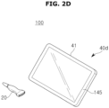
FIGS. 2A ,2B ,2C , and2D are views illustrating ultrasonic imaging devices according to an embodiment. - Referring to
FIGS. 2A and2B ,ultrasonic imaging devices main display 121 and thesub display 122 may be implemented as a touch screen. At least one of themain display 121 and thesub display 122 may display ultrasonic images or a variety of information processed by theultrasonic imaging devices main display 121 and thesub display 122 may be implemented as a touch screen and provide a GUI, so that data for controlling theultrasonic imaging devices main display 121 may display an ultrasonic image, and thesub display 122 may display a control panel for controlling the display of the ultrasonic image in the form of a GUI. Thesub display 122 may receive data for controlling the display of images through a control panel displayed in a GUI form. For example, a time gain compensation (TGC) button, a Freeze button, a trackball, a jog switch, a knob, and the like may be provided as a GUI on thesub display 122. - The
ultrasonic imaging devices main display 121 using input control data. Theultrasonic imaging devices probe 20 by wire or wirelessly to transmit and receive ultrasonic signals to and from the object. - Referring to
FIG. 2B , theultrasonic imaging device 40b may further include acontrol panel 165 in addition to themain display 121 and thesub display 122. Thecontrol panel 165 may include a button, a trackball, a jog switch, a knob, and the like, and may receive data for controlling theultrasonic imaging device 40b from the user. For example, thecontrol panel 165 may include a time gain compensation (TGC)button 171, aFreeze button 172, and the like. TheTGC button 171 is a button for setting a TGC value for each depth of the ultrasonic images. When detecting the input of theFreeze button 172 while scanning an ultrasonic image, theultrasonic imaging device 40b may maintain the display of the frame image at that point in time. - A button, a trackball, a jog switch, a knob, and the like included in the
control panel 165 may be provided as a GUI on themain display 121 or thesub display 122. Theultrasonic imaging devices probe 20 to transmit and receive ultrasonic signals to and from the object. - Referring to
FIGS. 2C and2D , theultrasonic imaging device 40c may also be implemented in a portable form. The portableultrasonic imaging device 40c may include, for example, a smart phone, laptop computer, PDA, tablet PC, etc., which include a probe and an application, but is not limited thereto. - The
ultrasonic imaging device 40c may include amain body 41. Referring toFIG. 2C , theprobe 20 may be connected to one side of themain body 41 by wire. To this end, themain body 41 may include a connection terminal through which a cable connected to theprobe 20 may be attached and detached, and theprobe 20 may include a connection terminal through which a cable connected to themain body 41 may be attached and detached. - Referring to
FIG. 2D , theprobe 20 may be wirelessly connected to theultrasonic imaging device 40. Themain body 41 may include an input/output interface (e.g., a touch screen) 145 (140 and 170). The input/output interface 145 may display ultrasonic images, a variety of information processed by the ultrasonic imaging devices, a GUI, and the like. - An ultrasonic image may be displayed on the input/
output interface 145. Theultrasonic imaging device 40c may correct the ultrasonic image displayed on the input/output interface 145 using Al. Theultrasonic imaging device 40c may provide an alarm informing using various audio-visual tools, such as graphics, sound, and vibration, information about lesions among the ultrasonic images displayed on the input/output interface 145 using AI. - The
ultrasonic imaging device 40c may output a control panel displayed in a GUI form through the input/output interface 145. - Hereinafter, a structure of the probe, which obtains three-dimensional images by rotating a transducer array around a rotation shaft, will be described in detail.
-
FIG. 3 is a view illustrating rotation of a transducer array of an ultrasonic probe,FIGS. 4A and 4B are views illustrating various types of a conventional signal connector, andFIGS. 5A and 5B , which are views for explaining a space occupied by a flexible printed circuit board as a signal connector, are views illustrating winding of the flexible printed circuit board according to an embodiment. - Referring to
FIG. 3 , thetransducer array 115 may be connected to a rotation shaft d and rotated around the rotation shaft d by amotor 210. - The ultrasonic signal emitted in two dimensions by the
transducer array 115 may obtain a three-dimensional ultrasonic image as thetransducer array 115 rotates. - In this type of the
ultrasonic probe 20, loads are applied to the signal connector as thetransducer array 115 rotates, and various types of signal connectors may be used to withstand the loads. - As illustrated in
FIG. 4A , a coaxial cable may be used as a signal connector, and as illustrated inFIG. 4B , a flexible printed circuit board (FPCB) 230 may also be used. In addition, the signal connector may be used in various ways. - In the case of using the coaxial cable as a signal connector, the coaxial cable easily distributes the loads so that durability may increase, but manufacturing costs increase so that manufacturing may not be easy. In addition, a space occupied by the coaxial cable may increase due to the increase in signal channels.
- In the case of using the FPCB as a signal connector, the manufacturing cost is reduced so that the manufacturing may be easy and a space occupied by the FPCB may be small compared to the coaxial cable, but the durability may be reduced because it is difficult to distribute the loads.
- Even though the FPCB occupies less space compared to the coaxial cable, as the number of signal channels continues to increase, the signal channels occupy a lot of space in the
ultrasonic probe 20, which may increase the volume of the product. - In the disclosure, a structure of the FPCB is disclosed to solve problems in space utilization that occur when the FPCB is used as a signal connector.
- As the flexible printed
circuit board 230 having the same shape as inFIG. 5A is wound in the form of a clockwork as illustrated inFIG. 5B , the loads resulting from the rotation of thetransducer array 115 may be better distributed, thereby improving durability. - That is, as the flexible printed
circuit board 230 wound in the form of a clockwork is repeatedly wound and unwound when thetransducer array 115 rotates, the loads applied to the flexible printedcircuit board 230 may be distributed. - Hereinafter, a structure of the flexible printed
circuit board 230 will be described in detail. -
FIGS. 6A to 6C are views for explaining a new structure of the flexible printed circuit board according to an embodiment, andFIG. 7 is a view illustrating the ultrasonic probe into which the flexible printed circuit board is inserted. - As illustrated in
FIG. 7 , theultrasonic probe 20 may include thetransducer array 115 connected to the rotation shaft d, and themotor 210 provided to rotate the transducer around the rotation shaft d. - The
ultrasonic probe 20 may also include a printedcircuit board 220 provided to output a driving signal for driving thetransducer array 115 and the flexible printedcircuit board 230 as a signal connector electrically connected to the printedcircuit board 220 to transmit the driving signal to thetransducer array 115. - The detailed structure of the flexible printed
circuit board 230 will be described below with reference toFIG. 6 . - The flexible printed
circuit board 230 may include anarray terminal 231 electrically connected to thetransducer array 115, afirst terminal 232 electrically connected to one portion of the printed circuit board, afirst connection part 233 connecting thearray terminal 231 and thefirst terminal 232, asecond terminal 234 electrically connected to the other portion of the printed circuit board, and asecond connection part 235 connecting thearray terminal 231 and thesecond terminal 234. - The
array terminal 231 may transmit or receive signals to or from the transducer by being electrically connected to thetransducer array 115. - The
array terminal 231 may be separated into t two or more strands and each connected to the printed circuit board. The disclosure exemplifies two strands, but is not limited thereto, and the array terminal may be separated into two or more strands. - The
first terminal 232 may be electrically connected to one portion of the printed circuit board, and thesecond terminal 234 may be electrically connected to the other portion of the printed circuit board. - The
first connection part 233 may connect thefirst terminal 232 and thearray terminal 231, and thesecond connection part 235 may connect thesecond terminal 234 and thearray terminal 231. - A first strand including the
first connection part 233 and thefirst terminal 232 may be folded at least twice to be overlapped with a second strand including thesecond connection part 235 and thesecond terminal 234. - Specifically, in the form illustrated in
FIG. 6A , the first strand may be folded once as illustrated inFIG. 6B , and folded once more as illustrated inFIG. 6C to be overlapped with the second strand. - In this case, the
first terminal 232 and thesecond terminal 234 are not overlapped with each other, and thefirst connection part 233 and thesecond connection part 235 may be overlapped with each other. - That is, the
first connection part 233 may be overlapped with thesecond connection part 235 by being folded twice. - Although the disclosure has been described as an example in which the
first connection part 233 is folded twice as illustrated inFIG. 6 , the disclosure is not limited thereto, and thefirst connection part 233 may be overlapped with thesecond connection part 235 by being folded twice or more. - In this case, the
first connection part 233 and thesecond connection part 235 may be completely overlapped with each other depending on a structural design. - Because positions of the
first terminal 232 and thesecond terminal 234 do not match as thefirst connection part 233 is folded and overlapped with thesecond connection part 235 so that thefirst terminal 232 and thesecond terminal 234 may not be electrically connected to the printed circuit board, by forming thefirst connection part 233, which is a connection part to be folded, longer, when thefirst connection part 233 is folded and overlapped with thesecond connection part 235, thefirst terminal 232 and thesecond terminal 234 may be positioned on the same line. - In this case, the overlapped portion may be wound around the rotation shaft d, as illustrated in
FIG. 5B . - Specifically, a portion where the
first connection part 233 and thesecond connection part 235 are overlapped with each other may be wound around the rotation shaft d. - As the
first connection part 233 and thesecond connection part 235 is overlapped with each other, the space occupied by the flexible printedcircuit board 230 in theultrasonic probe 20 may be reduced, thereby preventing a size of theultrasonic probe 20 from increasing. -
FIG. 8 is a view of the ultrasonic probe according to an embodiment viewed from a side, andFIG. 9 is a view of the ultrasonic probe according to an embodiment viewed from the front. - As described above, the ultrasonic array may is rotated around the rotation shaft d by the
motor 210, and the flexible printedcircuit board 230 may be wound around the rotation shaft d in the form of a clockwork. - In this case, a rotation radius R1 at which the ultrasonic array rotates may be larger than a radius R2 at which the flexible printed
circuit board 230 is wound around the rotation shaft d. - As described above, the
first connection part 233 and thesecond connection part 235 may be overlapped with each other, and a length of thetransducer array 115 in an axial (lateral) direction may be longer than a width of the overlappedfirst connection part 233 andsecond connection part 235. - Accordingly, the space utilization of the
ultrasonic probe 20 may be increased. -
FIGS. 10A and 10B are views for explaining a structure of a flexible printed circuit board according to another embodiment. - Although the disclosure has been described as an example in which the
first connection part 233 is folded twice or more and overlapped with thesecond connection part 235 as illustrated inFIG. 6 , thefirst connection part 233 may be folded only once and overlapped with thesecond connection part 235. - That is, in the flexible printed
circuit board 230 having the structure illustrated inFIG. 10A , thefirst connection part 233 may be folded once and overlapped with thesecond connection part 235 in the form illustrated inFIG. 10B . - As is apparent from the above, according to the disclosure, an ultrasonic probe and a flexible printed circuit board (FPCB) can reduce a space occupied by a signal connector by folding and overlapping the flexible printed circuit board as the signal connector.
- In addition, the ultrasonic probe and the flexible printed circuit board can better withstand a load caused by rotation of a transducer array by overlapping the flexible printed circuit board and winding the overlapped flexible printed circuit board around a rotation shaft.
- The embodiments disclosed with reference to the accompanying drawings have been described above. It will be understood by those skilled in the art that various changes in form and details may be made therein without departing from the spirit and scope of the disclosure as defined by the appended claims. The disclosed embodiments are illustrative and should not be construed as limiting.
Claims (14)
- An ultrasonic probe comprising:a transducer array connected to a rotation shaft;a motor provided to rotate the transducer array around the rotation shaft;a printed circuit board provided to output a driving signal for driving the transducer array; anda flexible printed circuit board electrically connected to the printed circuit board to transmit the driving signal to the transducer array,wherein the flexible printed circuit board comprises:an array terminal electrically connected to the transducer array;a first terminal electrically connected to one portion of the printed circuit board;a first connection part connecting the array terminal and the first terminal;a second terminal electrically connected to the other portion of the printed circuit board; anda second connection part connecting the array terminal and the second terminal, andwherein the first connection part and the second connection part are overlapped with each other and wound around the rotation shaft.
- The ultrasonic probe according to claim 1, wherein
the first connection part is folded twice or more and overlapped with the second connection part. - The ultrasonic probe according to claim 2, wherein
the first connection part is formed to be longer than the second connection part. - The ultrasonic probe according to claim 1, wherein
the first connection part and the second connection part are completely overlapped with each other. - The ultrasonic probe according to claim 4, wherein
a portion where the first connection part and the second connection part are overlapped with each other is wound around the rotation shaft. - The ultrasonic probe according to claim 1, wherein
a radius at which the flexible printed circuit board is wound around the rotation shaft is smaller than a rotation radius of the transducer array. - The ultrasonic probe according to claim 1, wherein
a length of the transducer array in a lateral direction is longer than a width of the overlapped first connection part and second connection part. - A flexible printed circuit board, which is configured to transmit a driving signal from a printed circuit board to a transducer array connected to a rotation shaft, comprising:an array terminal electrically connected to the transducer array;a first terminal electrically connected to one portion of the printed circuit board;a first connection part connecting the array terminal and the first terminal;a second terminal electrically connected to the other portion of the printed circuit board; anda second connection part connecting the array terminal and the second terminal,wherein the first connection part and the second connection part are overlapped with each other and wound around the rotation shaft.
- The ultrasonic probe according to claim 8, wherein
the first connection part is folded twice or more and overlapped with the second connection part. - The ultrasonic probe according to claim 9, wherein
the first connection part is formed to be longer than the second connection part. - The ultrasonic probe according to claim 8, wherein
the first connection part and the second connection part are completely overlapped with each other. - The ultrasonic probe according to claim 11, wherein
a portion where the first connection part and the second connection part are overlapped with each other is wound around the rotation shaft. - The ultrasonic probe according to claim 8, wherein
a radius at which the flexible printed circuit board is wound around the rotation shaft is smaller than a rotation radius of the transducer array. - The ultrasonic probe according to claim 8, wherein
a length of the transducer array in a lateral direction is longer than a width of the overlapped first connection part and second connection part.
Applications Claiming Priority (1)
| Application Number | Priority Date | Filing Date | Title |
|---|---|---|---|
| KR1020230136056A KR20250052813A (en) | 2023-10-12 | 2023-10-12 | Ultrasonic probe and flexible printed circuit board |
Publications (2)
| Publication Number | Publication Date |
|---|---|
| EP4537764A1 true EP4537764A1 (en) | 2025-04-16 |
| EP4537764B1 EP4537764B1 (en) | 2026-03-25 |
Family
ID=89715724
Family Applications (1)
| Application Number | Title | Priority Date | Filing Date |
|---|---|---|---|
| EP24153591.3A Active EP4537764B1 (en) | 2023-10-12 | 2024-01-24 | Ultrasonic probe and flexible printed circuit board |
Country Status (3)
| Country | Link |
|---|---|
| US (1) | US12523753B2 (en) |
| EP (1) | EP4537764B1 (en) |
| KR (1) | KR20250052813A (en) |
Cited By (1)
| Publication number | Priority date | Publication date | Assignee | Title |
|---|---|---|---|---|
| US12523753B2 (en) * | 2023-10-12 | 2026-01-13 | Samsung Medison Co., Ltd. | Ultrasonic probe and flexible printed circuit board |
Citations (3)
| Publication number | Priority date | Publication date | Assignee | Title |
|---|---|---|---|---|
| WO2012160501A2 (en) * | 2011-05-23 | 2012-11-29 | Koninklijke Philips Electronics N.V. | Flexible board connecting method and ultrasonic probe |
| US20130172756A1 (en) * | 2012-01-02 | 2013-07-04 | General Electric Company | Systems and methods for connection to a transducer in ultrasound probes |
| KR20230136056A (en) | 2022-03-17 | 2023-09-26 | 애플 인크. | Enhanced single-dci multi-panel uplink transmissions |
Family Cites Families (11)
| Publication number | Priority date | Publication date | Assignee | Title |
|---|---|---|---|---|
| US5044053A (en) | 1990-05-21 | 1991-09-03 | Acoustic Imaging Technologies Corporation | Method of manufacturing a curved array ultrasonic transducer assembly |
| US6582371B2 (en) | 2001-07-31 | 2003-06-24 | Koninklijke Philips Electronics N.V. | Ultrasound probe wiring method and apparatus |
| US7491172B2 (en) | 2004-01-13 | 2009-02-17 | General Electric Company | Connection apparatus and method for controlling an ultrasound probe |
| JP2008187625A (en) | 2007-01-31 | 2008-08-14 | Nippon Dempa Kogyo Co Ltd | Convex-type ultrasonic probe |
| IN2013CN03726A (en) | 2010-11-18 | 2015-08-07 | Koninkl Philips Electronics Nv | |
| US20130172751A1 (en) | 2012-01-02 | 2013-07-04 | General Electric Company | Systems and methods for shock absorbing in ultrasound probes |
| JP6091755B2 (en) | 2012-01-24 | 2017-03-08 | 東芝メディカルシステムズ株式会社 | Ultrasonic probe and ultrasonic diagnostic apparatus |
| JP6271887B2 (en) | 2013-07-10 | 2018-01-31 | キヤノン株式会社 | Capacitive transducer, probe, and subject information acquisition apparatus |
| WO2019212068A1 (en) | 2018-04-30 | 2019-11-07 | 서강대학교 산학협력단 | Ultrasonic probe assembly using fpcb |
| CN113490555B (en) | 2019-02-22 | 2023-05-23 | 维蒙股份公司 | Flexible printed circuit board device for interfacing high density ultrasound matrix array transducers with integrated circuits |
| KR20250052813A (en) * | 2023-10-12 | 2025-04-21 | 삼성메디슨 주식회사 | Ultrasonic probe and flexible printed circuit board |
-
2023
- 2023-10-12 KR KR1020230136056A patent/KR20250052813A/en active Pending
-
2024
- 2024-01-24 EP EP24153591.3A patent/EP4537764B1/en active Active
- 2024-01-26 US US18/424,656 patent/US12523753B2/en active Active
Patent Citations (3)
| Publication number | Priority date | Publication date | Assignee | Title |
|---|---|---|---|---|
| WO2012160501A2 (en) * | 2011-05-23 | 2012-11-29 | Koninklijke Philips Electronics N.V. | Flexible board connecting method and ultrasonic probe |
| US20130172756A1 (en) * | 2012-01-02 | 2013-07-04 | General Electric Company | Systems and methods for connection to a transducer in ultrasound probes |
| KR20230136056A (en) | 2022-03-17 | 2023-09-26 | 애플 인크. | Enhanced single-dci multi-panel uplink transmissions |
Cited By (1)
| Publication number | Priority date | Publication date | Assignee | Title |
|---|---|---|---|---|
| US12523753B2 (en) * | 2023-10-12 | 2026-01-13 | Samsung Medison Co., Ltd. | Ultrasonic probe and flexible printed circuit board |
Also Published As
| Publication number | Publication date |
|---|---|
| US12523753B2 (en) | 2026-01-13 |
| EP4537764B1 (en) | 2026-03-25 |
| US20250123381A1 (en) | 2025-04-17 |
| KR20250052813A (en) | 2025-04-21 |
Similar Documents
| Publication | Publication Date | Title |
|---|---|---|
| KR102762540B1 (en) | Wireless ultrasound probe, ultrasound diagnostic apparatus connected to the wireless ultrasound probes and operating the same | |
| US11647986B2 (en) | Ultrasound diagnosis apparatus connected to wireless ultrasound probes and method of operating the same | |
| US11413010B2 (en) | Ultrasound diagnosis apparatus and method of operating the same | |
| US10130335B2 (en) | Ultrasonic diagnostic system | |
| US20160206284A1 (en) | Probe assembly, ultrasound imaging apparatus and controlling method of ultrasound imaging apparatus | |
| US20020138007A1 (en) | Ultrasonic probe including pointing devices for remotely controlling functions of an associated imaging system | |
| KR20230135035A (en) | Ultrasound diagnostic apparatus and operating the same | |
| EP4537764B1 (en) | Ultrasonic probe and flexible printed circuit board | |
| EP2901938B1 (en) | Ultrasonic probe and ultrasonic diagnostic apparatus including the same | |
| EP3627995B1 (en) | Ultrasound diagnosis apparatus and method of operating the same | |
| US11730449B2 (en) | Ultrasonic diagnostic system | |
| EP4538739A1 (en) | Probe capable of self-inspection, ultrasonic imaging system having the same, and method of controlling the same | |
| KR102580426B1 (en) | Ultrasound diagnostic apparatus and operating the same | |
| US20260009766A1 (en) | Ultrasonic apparatus and manufacturing method thereof | |
| EP4527309B1 (en) | Wireless ultrasonic probe | |
| EP4534215A1 (en) | Ultrasound probe, method of manufacturing the same, and structure combinable with main backing layer of the same | |
| US20250127487A1 (en) | Ultrasonic probe | |
| US20260108234A1 (en) | Ultrasound probe and ultrasound image providing method | |
| KR20240142940A (en) | Ultrasonic probe and ultrasound diagnosis apparatus including the same | |
| KR20240071209A (en) | Ultrasound diagnosis apparatus including wireless probe and operating method thereof | |
| KR20250085529A (en) | A probe and controlling method thereof | |
| CN120826194A (en) | Ultrasonic imaging system and control method thereof |
Legal Events
| Date | Code | Title | Description |
|---|---|---|---|
| PUAI | Public reference made under article 153(3) epc to a published international application that has entered the european phase |
Free format text: ORIGINAL CODE: 0009012 |
|
| STAA | Information on the status of an ep patent application or granted ep patent |
Free format text: STATUS: REQUEST FOR EXAMINATION WAS MADE |
|
| 17P | Request for examination filed |
Effective date: 20241105 |
|
| AK | Designated contracting states |
Kind code of ref document: A1 Designated state(s): AL AT BE BG CH CY CZ DE DK EE ES FI FR GB GR HR HU IE IS IT LI LT LU LV MC ME MK MT NL NO PL PT RO RS SE SI SK SM TR |
|
| GRAP | Despatch of communication of intention to grant a patent |
Free format text: ORIGINAL CODE: EPIDOSNIGR1 |
|
| STAA | Information on the status of an ep patent application or granted ep patent |
Free format text: STATUS: GRANT OF PATENT IS INTENDED |
|
| INTG | Intention to grant announced |
Effective date: 20250710 |
|
| GRAJ | Information related to disapproval of communication of intention to grant by the applicant or resumption of examination proceedings by the epo deleted |
Free format text: ORIGINAL CODE: EPIDOSDIGR1 |
|
| STAA | Information on the status of an ep patent application or granted ep patent |
Free format text: STATUS: REQUEST FOR EXAMINATION WAS MADE |
|
| GRAP | Despatch of communication of intention to grant a patent |
Free format text: ORIGINAL CODE: EPIDOSNIGR1 |
|
| STAA | Information on the status of an ep patent application or granted ep patent |
Free format text: STATUS: GRANT OF PATENT IS INTENDED |
|
| INTC | Intention to grant announced (deleted) | ||
| INTG | Intention to grant announced |
Effective date: 20251105 |
|
| GRAS | Grant fee paid |
Free format text: ORIGINAL CODE: EPIDOSNIGR3 |
|
| GRAA | (expected) grant |
Free format text: ORIGINAL CODE: 0009210 |
|
| STAA | Information on the status of an ep patent application or granted ep patent |
Free format text: STATUS: THE PATENT HAS BEEN GRANTED |
|
| AK | Designated contracting states |
Kind code of ref document: B1 Designated state(s): AL AT BE BG CH CY CZ DE DK EE ES FI FR GB GR HR HU IE IS IT LI LT LU LV MC ME MK MT NL NO PL PT RO RS SE SI SK SM TR |
|
| REG | Reference to a national code |
Ref country code: CH Ref legal event code: F10 Free format text: ST27 STATUS EVENT CODE: U-0-0-F10-F00 (AS PROVIDED BY THE NATIONAL OFFICE) Effective date: 20260325 Ref country code: GB Ref legal event code: FG4D |
|
| REG | Reference to a national code |
Ref country code: DE Ref legal event code: R096 Ref document number: 602024003329 Country of ref document: DE |
|
| REG | Reference to a national code |
Ref country code: IE Ref legal event code: FG4D |
|
| PG25 | Lapsed in a contracting state [announced via postgrant information from national office to epo] |
Ref country code: RS Free format text: LAPSE BECAUSE OF FAILURE TO SUBMIT A TRANSLATION OF THE DESCRIPTION OR TO PAY THE FEE WITHIN THE PRESCRIBED TIME-LIMIT Effective date: 20260625 |
|
| PG25 | Lapsed in a contracting state [announced via postgrant information from national office to epo] |
Ref country code: GR Free format text: LAPSE BECAUSE OF FAILURE TO SUBMIT A TRANSLATION OF THE DESCRIPTION OR TO PAY THE FEE WITHIN THE PRESCRIBED TIME-LIMIT Effective date: 20260626 |
|
| REG | Reference to a national code |
Ref country code: LT Ref legal event code: MG9D |
|
| PG25 | Lapsed in a contracting state [announced via postgrant information from national office to epo] |
Ref country code: LT Free format text: LAPSE BECAUSE OF FAILURE TO SUBMIT A TRANSLATION OF THE DESCRIPTION OR TO PAY THE FEE WITHIN THE PRESCRIBED TIME-LIMIT Effective date: 20260325 |
|
| PG25 | Lapsed in a contracting state [announced via postgrant information from national office to epo] |
Ref country code: NO Free format text: LAPSE BECAUSE OF FAILURE TO SUBMIT A TRANSLATION OF THE DESCRIPTION OR TO PAY THE FEE WITHIN THE PRESCRIBED TIME-LIMIT Effective date: 20260625 |
|
| PG25 | Lapsed in a contracting state [announced via postgrant information from national office to epo] |
Ref country code: SE Free format text: LAPSE BECAUSE OF FAILURE TO SUBMIT A TRANSLATION OF THE DESCRIPTION OR TO PAY THE FEE WITHIN THE PRESCRIBED TIME-LIMIT Effective date: 20260325 Ref country code: FI Free format text: LAPSE BECAUSE OF FAILURE TO SUBMIT A TRANSLATION OF THE DESCRIPTION OR TO PAY THE FEE WITHIN THE PRESCRIBED TIME-LIMIT Effective date: 20260325 |
|
| PG25 | Lapsed in a contracting state [announced via postgrant information from national office to epo] |
Ref country code: HR Free format text: LAPSE BECAUSE OF FAILURE TO SUBMIT A TRANSLATION OF THE DESCRIPTION OR TO PAY THE FEE WITHIN THE PRESCRIBED TIME-LIMIT Effective date: 20260325 |
|
| PG25 | Lapsed in a contracting state [announced via postgrant information from national office to epo] |
Ref country code: LV Free format text: LAPSE BECAUSE OF FAILURE TO SUBMIT A TRANSLATION OF THE DESCRIPTION OR TO PAY THE FEE WITHIN THE PRESCRIBED TIME-LIMIT Effective date: 20260325 |
|
| PG25 | Lapsed in a contracting state [announced via postgrant information from national office to epo] |
Ref country code: BG Free format text: LAPSE BECAUSE OF FAILURE TO SUBMIT A TRANSLATION OF THE DESCRIPTION OR TO PAY THE FEE WITHIN THE PRESCRIBED TIME-LIMIT Effective date: 20260325 |
|
| REG | Reference to a national code |
Ref country code: NL Ref legal event code: MP Effective date: 20260325 |