EP4537730A1 - Dishwasher - Google Patents
Dishwasher Download PDFInfo
- Publication number
- EP4537730A1 EP4537730A1 EP23203344.9A EP23203344A EP4537730A1 EP 4537730 A1 EP4537730 A1 EP 4537730A1 EP 23203344 A EP23203344 A EP 23203344A EP 4537730 A1 EP4537730 A1 EP 4537730A1
- Authority
- EP
- European Patent Office
- Prior art keywords
- hood
- dishwasher
- kinematic
- damper device
- actuator
- Prior art date
- Legal status (The legal status is an assumption and is not a legal conclusion. Google has not performed a legal analysis and makes no representation as to the accuracy of the status listed.)
- Granted
Links
Images



Classifications
-
- A—HUMAN NECESSITIES
- A47—FURNITURE; DOMESTIC ARTICLES OR APPLIANCES; COFFEE MILLS; SPICE MILLS; SUCTION CLEANERS IN GENERAL
- A47L—DOMESTIC WASHING OR CLEANING; SUCTION CLEANERS IN GENERAL
- A47L15/00—Washing or rinsing machines for crockery or tableware
- A47L15/0076—Washing or rinsing machines for crockery or tableware of non-domestic use type, e.g. commercial dishwashers for bars, hotels, restaurants, canteens or hospitals
- A47L15/0081—Washing or rinsing machines for crockery or tableware of non-domestic use type, e.g. commercial dishwashers for bars, hotels, restaurants, canteens or hospitals with vertical sliding closing doors, e.g. hood-type dishwashers
Definitions
- the present invention relates to a dishwasher in the form of a hood-type dishwasher. Aspects of the present invention also relate to an actuating assembly for hood-type dishwashers.
- Dishwashers configured as hood-type dishwashers generally comprise a treatment chamber for cleaning washware.
- a wash tank is arranged below the treatment chamber, such that liquid that is sprayed onto the washware is able to flow back from the treatment chamber into the wash tank by means of gravity.
- Washing liquid which is generally water, is located in the wash tank, whereas the detergent is added to the washing liquid if required.
- hood-type dishwashers racks loaded with washware are pushed manually into the treatment chamber from an entry side and after the completion of a washing program are manually removed from the treatment chamber via an exit side.
- a hood or cover of the dishwasher may be lifted and lowered to either open or close the entry and exit sides of the treatment chamber.
- Hood-type dishwashers are used primarily (but not exclusively) for relatively small sculleries, such as for example in relatively small canteens, in particular school canteens, or in the catering field.
- the use of such dishwashers is characterized by said dishwashers being able to be used in sculleries, in which generally only a limited floor space is available.
- An industrial dishwasher in particular a hood-type dishwasher, differs from a household dishwasher particularly in that an industrial dishwasher has to be designed such that, depending on the selected treatment program, running times of 1 to 5 minutes may be employed, whereas household dishwashers generally have running times of several hours. Due to the short program times required in industrial dishwashers, techniques used in household dishwashers are generally not able to be transferred easily to industrial dishwashers.
- Loading and unloading of hood-type dishwashers typically takes place manually, i.e., after carrying out pre-clearing and/or pre-washing on the entry side, the operator pushes the rack to be cleaned manually from an entry table into the opened dishwasher and closes the hood. Once the hood of the dishwasher is closed, a cleaning cycle begins. Once the cleaning cycle has been completed, the operator opens the hood and pushes the cleaned rack from the machine onto an exit table arranged on the exit side of the treatment chamber.
- actuating mechanisms have been develobed, which may be used to automatically open and close the hood of the dishwasher before and after the respective washing programs.
- automatically opening hoods for hood-type dishwashers significantly reduces the amount of manual labour required
- such mechanisms often rely on hydraulic cylinders, which are used to generate the force required to lift and lower the hood.
- hydraulic cylinders are typically very reliable, they do not normally allow for manual operation of the hood if there is a problem with the cylinder (i.e., the cylinder got stuck).
- a dishwasher of the hood-type comprising:
- the hood may be actuated both automatically and manually.
- an actuator for example an electric linear actuator
- the actuator is connected to the hood via a kinematic that transfers the forces of the actuator into vertically sliding movement of the hood.
- the kinematic of the present invention not only transfers the forces generated by the actuator to the hood but also enables manual movement of the hood, e.g., when the actuator is out of order.
- the rod of the linear actuator may not be pushed inside or pulled out of the cylinder when the actuator is not operating.
- the present invention suggests configuring the kinematic movable in such a way that the hood may still be transferred between its closed and open position manually, when the actuator is stuck.
- the kinematic may be collapsible or compressible, preferably exclusively when the actuator is inoperable/stuck.
- the kinematic of the present invention allows the user to operate the hood, even if the actuator is out of order. This facilitates further use of the hood-type dishwasher in a conventional (manual) manner, until the actuator can be repaired or replaced.
- the present invention suggests providing a damper device as part of the kinematic, wherein the damper device is configured to damper the movement of the hood when the hood is manually operated.
- the damper device ensures that the hood will slowly move from its open position into its closed position, even during manual operation.
- the damper device is configured to remain inactive, during automatic transfer of the hood between its closed position and its open position.
- the damper device of the present invention will not hinder the movement of the hood during automatic operation.
- the actuator of the present invention is not required to provide higher actuating forces due to the presence of the damper device.
- the damper device is arranged between the actuator and the hood. This configuration corresponds to a particularly space saving arrangement of the damper device.
- the damper device may be arranged between the hood and the supporting casing of the dishwasher.
- the kinematic of the actuating assembly is configured to allow for relative movement between the actuator and the hood during manual operation and to be extended during automatic operation. As will be explained in more detail below, the kinematic may remain in its extended position during automatic operation by means of the weight of the hood alone.
- the damper device comprises a linear damper cylinder, particularly a gas cylinder.
- the damper device may be any other suitable device, such as a hydraulic cylinder etc.
- the linear damper cylinder is transferable between an extended configuration and a compressed configuration, wherein the linear damper cylinder is configured to remain in its extended configuration during automatic transfer of the hood between its closed position and its open position, and wherein the linear damper cylinder is configured to move towards its compressed configuration when the hood is manually operated.
- the kinematic comprises a first link and a second link, wherein the first and second links are movable with respect to each other so as to allow a relative movement between the hood and the actuator, during manual operation of the hood.
- first and second links that are movable with respect to each other is a particularly simple way of constructing the kinematic of the present invention.
- the kinematic may alternatively comprise any type of link between the actuator and the hood that is configured to transfer pulling forces but not push forces. Some examples include chains or ropes.
- first and second links are movable with respect to each other in a longitudinal direction. Accordingly, the first and second links should be movable with respect to each other in the vertical direction that the hood slides in.
- the first and second links each comprise at least one bar, the bars of the first and second links being connected to each other via a slot arranged in one of the bars. This arrangement allows for a particularly smooth transition between the open and closed positions of the hood, when the actuator is inoperable.
- the damper device is arranged in parallel with the first and second links. This arrangement is particularly space saving.
- the dishwasher comprises a second damper device arranged in parallel with the first damper device and configured to dampen the movement of the hood when the hood is manually operated.
- an actuating assembly for a hood-type dishwasher comprising:
- the kinematic comprises a first link and a second link, wherein the first and second links are movable with respect to each other, when the kinematic is moved between its extended configuration and its compressed configuration.
- the damper device is arranged in parallel with the first and second links.
- the actuating assembly comprises a second damper device arranged in parallel with the damper device and configured to dampen the movement of the hood when the hood is manually operated, wherein the two damper devices are preferably arranged on opposite sides of the first and second links.
- Fig. 1 is a reproduction of Fig. 1 of WO2013/109841 , showing a conventional, manually operated hood-type dishwasher 1, some parts of which shall be described by way of background below.
- the conventional dishwasher comprises a supporting casing 2, tank 3 and a hood 5, carried in a vertically sliding manner by the casing 2 over the tank 3, so as to selectively take a first open position (shown in Fig. 1 ) and a second, closed position (not shown).
- the hood 5 In the closed position, the hood 5 covers a treatment chamber 6 with the tank 3. In the open position of the hood, the treatment chamber 6 is accessible to insert/remove dishware. Dishes to be washed are arranged with the aid of a basket (known and not shown for the sake of simplicity).
- the hood 5 is carried in vertically sliding manner by respective rear vertical guides 7 carried by the casing 2, so as to be able to selectively assume the open and the closed position defined above passing through an intermediate or "mid stroke" position.
- the dishwasher 1 further comprises a control device 8 of the vertical sliding movement of the hood 5 comprising a frame-shaped handle 9 surrounding the hood 5 along at least one front side 10 and a first of two opposite lateral sides 11,12 of the hood 5; the handle 9 is carried by the casing 2 so as to pivot about a first horizontal rotation axis A arranged behind the hood 5 and is restrained in an articulated manner to at least the first lateral side 11 of the hood 5, so as to receive in use a vertical stress H, indicated by the arrow in figure 1 , proportional to the weight of the hood 5 itself.
- a control device 8 of the vertical sliding movement of the hood 5 comprising a frame-shaped handle 9 surrounding the hood 5 along at least one front side 10 and a first of two opposite lateral sides 11,12 of the hood 5; the handle 9 is carried by the casing 2 so as to pivot about a first horizontal rotation axis A arranged behind the hood 5 and is restrained in an articulated manner to at least the first lateral side 11 of the
- the frame-shaped handle 9 forms on its laying plane a closed loop of essentially rectangular shape and comprises a front, essentially rectilinear holding position 14, a pair of opposite side arms 15 (also rectilinear in the illustrated example, only one of which is visible in the figures) and a rear C-shaped portion 16, which portion 16 is directly connected to the elastic means 13 and which form an angle with the rest of the handle 9, as described in greater detail below.
- the hood 5 consists of a generally parallelepiped-shaped shell delimited by the aforesaid front side 10 and lateral sides 11,12, as well as by a rear side 17, all defined by flat metallic panels, and the arms 15 are arranged parallel and facing the lateral sides 11,12.
- the handle 9 is restrained to the first lateral side 11 of the hood (and also to the second side 12, by means of a dual structure symmetric to the one which will be described now) by means of a link rod 18, which ( figure 5 ) has a first end 19 and a second end 20, opposite to each other, which are respectively restrained and hinged, the end 19 to the lateral side 11, near a lower edge 21 of the hood 5 and towards the front side 10 of the hood 5, so as to be able to turn with respect to the hood 5 about a second axis B horizontal and parallel to axis A and facing the front side 10 of the hood, and the end 20 to the corresponding side arm 15 of the handle 9 arranged facing the side 11, so as to be able to turn with respect to the handle 9 about a third horizontal axis C, eccentric to the second axis B and arranged higher than the second axis B.
- the other side 12 of the hood 5 is provided with a second link rod 18 (not shown) symmetric with in figures 1-3 and having similar ends to the axes B and C and, consequently, the corresponding arm 15 facing it. Furthermore, in the first position of the hood 5, shown in figure 1 , the first axis A is arranged higher than the second axis B and the third axis C.
- the holding portion 14 of the handle 9 is arranged essentially parallel to axis A and crosswise with respect to the side arms 15; in the case in point, the handle 9 is restrained and hinged to the vertical guides 7, laterally and outside the same, by means of respective L-folded ends 32 of the side arms 15 which ends are reciprocally coaxial and opposite to the holding portion 14; the ends 32 idling and laterally crossing through the guides 7 ( figure 4 ) to define axis A, forming a pair pins 33 belonging to the rear portion 16 of the
- the handle 9 is restrained of respective handle 9 and hinged to the guides 7 near an upper end 34 of the latter, away from the tank 3, at a height chosen so that the axis A is aligned essentially coplanar with the holding portion 14 when the hood 5 is in an intermediate mid stroke position between the first and second position, shown in figure 3 , in which the arms 15 are arranged essentially horizontal.
- a pair of helical springs 35 accommodated in the casing 2 are substantially at the guides 7; first ends 36 of the springs 35 are restrained to a pedestal 37 of the casing 2, on the side opposite to the vertical guides 7, and second ends 38 of the springs 35, opposite to the ends 36, are directly restrained to the handle 9, eccentrically to axis A, and at the side opposite to the front side 10 of the hood 5, in the case in point to the rear portion 16 by means of belts 39.
- the rear portion 16 of the handle 9, arranged facing side 17, is arranged on the side opposite to the front portion 14 with respect to axis A, and is hinged to the vertical guides 7, so as to turn about axis A along with the arms 15 and to the front portion 14, by means of the pair of opposite hinging pins 33, pins 33 which define axis A;
- the arms 15 radially extend so as to protrude from a pin 33 each;
- the rear portion 16 further comprises a pair of second arms 40 ( figure 4 ), which each radially protrude in overhanging manner from a respective pin 33 in a direction opposite to the overhanging direction of the corresponding arm 15 and which forms, with the latter direction and on a plane perpendicular to axis A, an obtuse angle K different from 180'.
- the rear portion 16 further comprises a cross-bar 41, which connects the free ends of the arms 40 to each other.
- each arm 40 is formed by a pair of plates 42 fixed in angularly integral manner to a pin 33 and joined at the free end of arms 40 by an extension of the cross-bar 41;
- the springs 35 are restrained to the cross-bar 41, being coupled to the extension thereof arranged between the plates 42 by means of the belts 39.
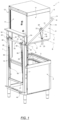
- FIG. 2 there is shown a schematic perspective view of a hood-type dishwasher according to an embodiment of the present invention. Parts no longer specifically mentioned with respect to FIG. 2 are generally identical to corresponding parts of the conventional hood-type dishwasher shown in FIG. 1 .
- the dishwasher 200 of FIG. 2 comprises an actuating assembly 202, which enables automatic and manual operation of the hood, i.e., transfer of the hood 5 between its open position (shown in FIG. 2 ) and is closed position (not shown) automatically and by hand.
- the actuating assembly 202 is, on one end, connected to the pedestal 237 of the casing 2. On an opposite end, the actuating assembly 202 is connected to the cross-bar 241. In particular, a first end of an actuator 204, particularly an electric linear actuator 204, is connected to the pedestal 237. A rod of the linear actuator 204 is connected to the cross-bar 241 via a kinematic 206 of the actuating assembly.
- FIG. 2 shows the linear actuator 204 in its retracted configuration, i.e., when the rod is partly or fully received within the cylinder.
- the hood 5 In this retracted configuration of the actuator 204, the hood 5 is in its open position.
- the linear actuator 204 may be extended, i.e., the rod will extend out of the cylinder, thereby enabling the cross-bar 241 to rotate under the weight of the hood 5. This will ultimately result in the hood being transferred into its closed position.
- the movement of the hood 5 between its open position and its closed position will be determined by the speed of which the rod is extended from the cylinder during this automatic operation.
- the kinematic 206 will maintain its dimensions, i.e., will not compress/fold/retract or extend, as will be explained in more detail below. Rather, during automatic operation, the kinematic 206 may be thought of as a single link connecting the distal end of the cylinder rod 208 to the cross-bar 241.
- the kinematic 206 is configured to be compressible/foldable, such that a rotation of the cross-bar 41 and thus a lifting of the hood 5 is possible even if the rod 208 is fixed.
- the kinematic 206 of the present invention may be configured in various different ways, some of which will be described in more detail with reference to FIGs. 3 to 6 .
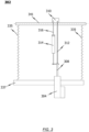
- FIG. 3 shows an actuating assembly 302 according to a first embodiment of the present invention.
- the actuating assembly 302 of FIG. 3 is shown connected to a schematic pedestal 337 and cross-bar 341.
- FIG. 3 also schematically shows two springs 335, which function identically to the springs 35 shown in FIG. 1 .
- the actuating assembly 302 of FIG. 3 comprises a linear actuator 304, which is connected to the pedestal 337 of the supporting casing of the dishwasher.
- a cylinder rod 308 of the linear actuator 304 is connected to a lobe 310 of the cross-bar 341 via a kinematic 306.
- the kinematic 306 comprises a flexible link 312 and a dampening device 314.
- the dampening device 314 is arranged in parallel with the flexible link 312.
- the flexible link 312 is schematically represented as a chain that is able to transfer pulling forces between the linear actuator 304 and the cross-bar 341.
- the flexible link 312 of the kinematic is not limited to a chain. Rather, any link that can transfer pulling forces/movements in automatic operation and is compressible/foldable/bendable, etc. to allow for compression of the kinematics may be used too.
- the flexible link 312 may be a rope or a plurality of links, which are connected in a linearly or angularly movable with respect to each other.
- the damper device 314 is shown as a gas cylinder.
- FIG. 3 shows an arrangement of the actuating assembly 302 in the closed configuration of the hood, irrespective of the manual or automatic operation. In the closed position of the hood, both the flexible link 312 and the damper device 314 are fully extended.
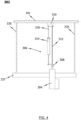
- FIG. 4 there is shown the embodiment of FIG. 3 in the open position of the hood, during automatic operation. Similar to FIG. 3 , the kinematic 306 of the actuating assembly 302 shown in FIG. 4 is also fully extended. In other words, neither the flexible link 312, nor the damper device 314 are compressed. Rather, the main difference between the positions in FIGs. 3 and 4 is that the cylinder rod 308 has been retracted in FIG. 4 , such that the actuator 304 transfers pulling movement to the lobe 310 and thus to the cross-bar 410 to open the hood 5. Since only a pulling-force is transferred from the linear actuator 304 to the lobe 310 of the cross-bar 341, the kinematic 306 remains in its extended configuration.
- the kinematic 306 still does not compress, and the damper device 314 remains inactive, i.e., the damper device does not act against the movement of the hood 5.
- a pushing force is not required to close the hood 5. Rather, the cylinder rod 308 of the linear actuator 304 will be slowly extended from the retracted position of FIG. 4 to the extended position of FIG. 3 , thereby gradually lowering the hood from its open position and stopping the hood from falling uncontrollably.
- FIG. 5 shows a configuration of the actuating assembly 302 according to the embodiment of FIG. 3 during manual operation.
- the linear actuator 302 is inoperable and stuck in its extended configuration shown in FIG. 3 .
- the flexible link 312 between the linear actuator 304 and the cross-bar 341 was not flexible but rigid, a manual operation of the hood would not be possible, since the linear actuator 304 would prevent rotation of the cross-bar 341.
- the flexible link 312 may be compressed/folded/bent, as explained more generally above, the hood 5 may be lifted by the operator manually at any point. During manual operation, the cross-bar will be rotated due to the lifting movement of the operator.
- the lobe 310 will be rotated together with the cross-bar 341, thereby reducing the distance between the distal end of the cylinder rod (now fixed) 308 and the lobe 310.
- This reduction in distance leads, on the one hand, to a compression of the flexible link 312 and, at the same time, to a compression of the damper device 314, which is a gas cylinder in this example.
- the damper device 314 may be configured in such a way that compression will be possible with no or no significant resistance. In other words, air within the lower chamber shown in FIG. 5 may be pushed out of the cylinder without significant flow restrictions, such that the damper device remains largely inactive during the lifting movement of the hood, i.e., during compression of the kinematic 306.
- this will mean extending the rod 316 against an air cushion within the cylinder.
- the speed at which the hood 5 is lowered into its closed position during manual operation may be determined by the type and setting (e.g. throttle valve) of the damper device 314.
- FIG. 6 shows another embodiment of the actuating assembly 402 according to the present disclosure.
- the actuating assembly 402 comprises a linear actuator 404 with a cylinder rod 408, which is connected to a cross-bar 441 via a kinematic 406.
- the kinematic 406 of the actuating assembly 402 of FIG. 6 exclusively consists of one or more damper devices 414.
- the damper device 414 in FIG. 6 is a gas cylinder, which is arranged between the cylinder rod 408 of the actuator 404 and a lobe 410 of the cross-bar 441.
- FIG. 6 shows the embodiment of the actuating assembly 402 during manual operation (cf. FIG. 5 ).
- the gas cylinder 414 is and remains fully extended, irrespective of whether the hood 5 is in its opened or closed position. A compression of the damper device 414 during automatic operation is not possible, because the weight of the hood will keep pulling on the rod 416 of the damper device 414.
- FIG. 7 shows an actuating assembly 502 according to another embodiment of the present invention.
- the actuating assembly 502 of FIG. 7 may be connected to a pedestal and cross-bar (not shown) of a conventional dishwashes, such as the dishwasher of FIG. 1 .
- the actuating assembly 502 may thus be retro-fitted to existing dishwashers, so as to enable both automatic and (safe) manual operation of the conventional dishwasher.
- the flexible link 512 comprises three links 518, 520, 522, which are connected to each other in a longitudinally movable manner. In other words, the three links may move with respect to each other to compress and extent the flexible link 512.
- two links 520, 522 are arranged on opposite sides of a central link 518.
- the central link may include one or more longitudinal slot.
- Connectors 524, 526 may extend through the outer links 520, 522 and the slot(s) of the central link 518 to enable the outer links 520, 522 to move with respect to the central link 518 in a longitudinal direction, particularly during manual operation of the hood.
Landscapes
- Washing And Drying Of Tableware (AREA)
Abstract
Description
- The present invention relates to a dishwasher in the form of a hood-type dishwasher. Aspects of the present invention also relate to an actuating assembly for hood-type dishwashers.
- Dishwashers configured as hood-type dishwashers generally comprise a treatment chamber for cleaning washware. Generally, a wash tank is arranged below the treatment chamber, such that liquid that is sprayed onto the washware is able to flow back from the treatment chamber into the wash tank by means of gravity. Washing liquid, which is generally water, is located in the wash tank, whereas the detergent is added to the washing liquid if required.
- In hood-type dishwashers, racks loaded with washware are pushed manually into the treatment chamber from an entry side and after the completion of a washing program are manually removed from the treatment chamber via an exit side. To this end, a hood or cover of the dishwasher may be lifted and lowered to either open or close the entry and exit sides of the treatment chamber.
- Hood-type dishwashers are used primarily (but not exclusively) for relatively small sculleries, such as for example in relatively small canteens, in particular school canteens, or in the catering field. The use of such dishwashers is characterized by said dishwashers being able to be used in sculleries, in which generally only a limited floor space is available.
- An industrial dishwasher, in particular a hood-type dishwasher, differs from a household dishwasher particularly in that an industrial dishwasher has to be designed such that, depending on the selected treatment program, running times of 1 to 5 minutes may be employed, whereas household dishwashers generally have running times of several hours. Due to the short program times required in industrial dishwashers, techniques used in household dishwashers are generally not able to be transferred easily to industrial dishwashers.
- Loading and unloading of hood-type dishwashers typically takes place manually, i.e., after carrying out pre-clearing and/or pre-washing on the entry side, the operator pushes the rack to be cleaned manually from an entry table into the opened dishwasher and closes the hood. Once the hood of the dishwasher is closed, a cleaning cycle begins. Once the cleaning cycle has been completed, the operator opens the hood and pushes the cleaned rack from the machine onto an exit table arranged on the exit side of the treatment chamber.
- In order to reduce the amount of manual labour required when operating hood-type dishwashers, actuating mechanisms have been develobed, which may be used to automatically open and close the hood of the dishwasher before and after the respective washing programs. Although automatically opening hoods for hood-type dishwashers significantly reduces the amount of manual labour required, such mechanisms often rely on hydraulic cylinders, which are used to generate the force required to lift and lower the hood. Although such hydraulic cylinders are typically very reliable, they do not normally allow for manual operation of the hood if there is a problem with the cylinder (i.e., the cylinder got stuck).
- It is an object of the present invention to solve or at least ameliorate some of the problems associated with the prior-art. In particular, it is an object of the present invention to provide a dishwasher with an automatic hood lifting arrangement that is simple and cost-effective to manufacture and, at the same time, allows for safe operation of the hood even in case of failure of the actuating mechanism.
- According to one aspect of the present invention, there is provided a dishwasher of the hood-type comprising:
- a supporting casing;
- a tank arranged within the supporting casing;
- a hood carried in a vertically sliding manner over the tank, so as to be transferable between a closed position, in which the hood covers a treatment chamber, and an open position, in which the hood opens the treatment chamber for loading and/or unloading of dishware; and
- an actuating assembly comprising an actuator for automatically transferring the hood between its closed position and its open position, and vice versa, said actuating assembly comprising a kinematic connecting the actuator to the hood, the kinematic being moveable in such a way that the hood may be manually transferred between its closed position and its open position, and vice versa,
- According to the present invention, the hood may be actuated both automatically and manually. During automatic actuation, an actuator, for example an electric linear actuator, may be used to transfer the hood between its open and closed position. To this end, the actuator is connected to the hood via a kinematic that transfers the forces of the actuator into vertically sliding movement of the hood. However, the kinematic of the present invention not only transfers the forces generated by the actuator to the hood but also enables manual movement of the hood, e.g., when the actuator is out of order. As will be appreciated, particularly with electrical linear actuators, the rod of the linear actuator may not be pushed inside or pulled out of the cylinder when the actuator is not operating. In prior-art hood-type dishwashers, this problem lead to the hood of the dishwasher being stuck when the actuator was inoperable. The present invention suggests configuring the kinematic movable in such a way that the hood may still be transferred between its closed and open position manually, when the actuator is stuck. To this end, and as will be described in more detail below, the kinematic may be collapsible or compressible, preferably exclusively when the actuator is inoperable/stuck.
- The kinematic of the present invention allows the user to operate the hood, even if the actuator is out of order. This facilitates further use of the hood-type dishwasher in a conventional (manual) manner, until the actuator can be repaired or replaced. However, it was found that providing the opportunity to move the hood between its open and closed position even if the actuator is inoperable, it is associated with health and safety risks to the operator, because the weight of the hood is then no longer carried by the actuator but by the strength of the operator. If, during manual (emergency) operation of the hood, the operator releases the hood in its open position, the hood may fall down into its closed position very quickly due to gravity. A hood falling in such a way can cause significant harm to the operator or any assistant and must thus be avoided. In view of the above, the present invention suggests providing a damper device as part of the kinematic, wherein the damper device is configured to damper the movement of the hood when the hood is manually operated. The damper device ensures that the hood will slowly move from its open position into its closed position, even during manual operation.
- According to another embodiment, the damper device is configured to remain inactive, during automatic transfer of the hood between its closed position and its open position. In other words, the damper device of the present invention will not hinder the movement of the hood during automatic operation. Accordingly, the actuator of the present invention is not required to provide higher actuating forces due to the presence of the damper device.
- According to another embodiment, the damper device is arranged between the actuator and the hood. This configuration corresponds to a particularly space saving arrangement of the damper device. In an alternative embodiment, the damper device may be arranged between the hood and the supporting casing of the dishwasher.
- According to another embodiment, the kinematic of the actuating assembly is configured to allow for relative movement between the actuator and the hood during manual operation and to be extended during automatic operation. As will be explained in more detail below, the kinematic may remain in its extended position during automatic operation by means of the weight of the hood alone.
- According to another embodiment, the damper device comprises a linear damper cylinder, particularly a gas cylinder. Alternatively, the damper device may be any other suitable device, such as a hydraulic cylinder etc.
- According to another embodiment, the linear damper cylinder is transferable between an extended configuration and a compressed configuration, wherein the linear damper cylinder is configured to remain in its extended configuration during automatic transfer of the hood between its closed position and its open position, and wherein the linear damper cylinder is configured to move towards its compressed configuration when the hood is manually operated.
- According to another embodiment, the kinematic comprises a first link and a second link, wherein the first and second links are movable with respect to each other so as to allow a relative movement between the hood and the actuator, during manual operation of the hood. Using first and second links that are movable with respect to each other is a particularly simple way of constructing the kinematic of the present invention. However, the kinematic may alternatively comprise any type of link between the actuator and the hood that is configured to transfer pulling forces but not push forces. Some examples include chains or ropes.
- According to another embodiment, the first and second links are movable with respect to each other in a longitudinal direction. Accordingly, the first and second links should be movable with respect to each other in the vertical direction that the hood slides in.
- According to another embodiment, the first and second links each comprise at least one bar, the bars of the first and second links being connected to each other via a slot arranged in one of the bars. This arrangement allows for a particularly smooth transition between the open and closed positions of the hood, when the actuator is inoperable.
- According to another embodiment, the damper device is arranged in parallel with the first and second links. This arrangement is particularly space saving.
- According to yet another embodiment, the dishwasher comprises a second damper device arranged in parallel with the first damper device and configured to dampen the movement of the hood when the hood is manually operated.
- According to another aspect of the present disclosure, there is provided an actuating assembly for a hood-type dishwasher, said actuating assembly comprising:
- an actuator for automatically transferring the hood of a hood-type dishwasher between a closed position and an open position, and vice versa;
- a kinematic for connecting the actuator to the hood of the hood-type dishwasher, said kinematic being moveable between an extended configuration and a compressed configuration,
- at least one damper device configured to dampen the movement of the kinematic between the extended configuration and the compressed configuration.
- In another embodiment, the kinematic comprises a first link and a second link, wherein the first and second links are movable with respect to each other, when the kinematic is moved between its extended configuration and its compressed configuration.
- In another embodiment, the damper device is arranged in parallel with the first and second links.
- In another embodiment, the actuating assembly comprises a second damper device arranged in parallel with the damper device and configured to dampen the movement of the hood when the hood is manually operated, wherein the two damper devices are preferably arranged on opposite sides of the first and second links.
- The present invention shall now be described in more detail with reference to the embodiments shown in the accompanying drawings, in which:
- FIG. 1
- shows a conventional hood-type dishwasher;
- FIG. 2
- shows a hood-type dishwasher according to an embodiment of the present invention;
- FIG. 3
- shows a schematic embodiment of the actuator assembly according to the present invention in a closed position of the hood;
- FIG. 4
- shows the assembly of
FIG. 3 in its open position, during automatic actuation; - FIG. 5
- shows the actuating assembly of
FIG. 3 in the open position of the hood during manual operation; and - FIG. 6
- shows an alternative embodiment of the actuating assembly according to the present invention.
-
Fig. 1 is a reproduction ofFig. 1 ofWO2013/109841 , showing a conventional, manually operated hood-type dishwasher 1, some parts of which shall be described by way of background below. The conventional dishwasher comprises a supporting casing 2, tank 3 and ahood 5, carried in a vertically sliding manner by the casing 2 over the tank 3, so as to selectively take a first open position (shown inFig. 1 ) and a second, closed position (not shown). - In the closed position, the
hood 5 covers a treatment chamber 6 with the tank 3. In the open position of the hood, the treatment chamber 6 is accessible to insert/remove dishware. Dishes to be washed are arranged with the aid of a basket (known and not shown for the sake of simplicity). - In particular, the
hood 5 is carried in vertically sliding manner by respective rear vertical guides 7 carried by the casing 2, so as to be able to selectively assume the open and the closed position defined above passing through an intermediate or "mid stroke" position. - The dishwasher 1 further comprises a control device 8 of the vertical sliding movement of the
hood 5 comprising a frame-shaped handle 9 surrounding thehood 5 along at least one front side 10 and a first of two oppositelateral sides 11,12 of thehood 5; the handle 9 is carried by the casing 2 so as to pivot about a first horizontal rotation axis A arranged behind thehood 5 and is restrained in an articulated manner to at least the first lateral side 11 of thehood 5, so as to receive in use a vertical stress H, indicated by the arrow infigure 1 , proportional to the weight of thehood 5 itself. - In the example shown, the frame-shaped handle 9 forms on its laying plane a closed loop of essentially rectangular shape and comprises a front, essentially rectilinear holding position 14, a pair of opposite side arms 15 (also rectilinear in the illustrated example, only one of which is visible in the figures) and a rear C-shaped portion 16, which portion 16 is directly connected to the elastic means 13 and which form an angle with the rest of the handle 9, as described in greater detail below. The
hood 5 consists of a generally parallelepiped-shaped shell delimited by the aforesaid front side 10 andlateral sides 11,12, as well as by a rear side 17, all defined by flat metallic panels, and thearms 15 are arranged parallel and facing the lateral sides 11,12. - The handle 9 is restrained to the first lateral side 11 of the hood (and also to the
second side 12, by means of a dual structure symmetric to the one which will be described now) by means of a link rod 18, which (figure 5 ) has a first end 19 and asecond end 20, opposite to each other, which are respectively restrained and hinged, the end 19 to the lateral side 11, near a lower edge 21 of thehood 5 and towards the front side 10 of thehood 5, so as to be able to turn with respect to thehood 5 about a second axis B horizontal and parallel to axis A and facing the front side 10 of the hood, and theend 20 to thecorresponding side arm 15 of the handle 9 arranged facing the side 11, so as to be able to turn with respect to the handle 9 about a third horizontal axis C, eccentric to the second axis B and arranged higher than the second axis B. - The
other side 12 of thehood 5 is provided with a second link rod 18 (not shown) symmetric with infigures 1-3 and having similar ends to the axes B and C and, consequently, thecorresponding arm 15 facing it. Furthermore, in the first position of thehood 5, shown infigure 1 , the first axis A is arranged higher than the second axis B and the third axis C. - As mentioned, the holding portion 14 of the handle 9 is arranged essentially parallel to axis A and crosswise with respect to the
side arms 15; in the case in point, the handle 9 is restrained and hinged to the vertical guides 7, laterally and outside the same, by means of respective L-folded ends 32 of theside arms 15 which ends are reciprocally coaxial and opposite to the holding portion 14; the ends 32 idling and laterally crossing through the guides 7 (figure 4 ) to define axis A, forming a pair pins 33 belonging to the rear portion 16 of the In particular, the handle 9 is restrained of respective handle 9 and hinged to the guides 7 near anupper end 34 of the latter, away from the tank 3, at a height chosen so that the axis A is aligned essentially coplanar with the holding portion 14 when thehood 5 is in an intermediate mid stroke position between the first and second position, shown infigure 3 , in which thearms 15 are arranged essentially horizontal. - A pair of helical springs 35 accommodated in the casing 2 are substantially at the guides 7; first ends 36 of the springs 35 are restrained to a pedestal 37 of the casing 2, on the side opposite to the vertical guides 7, and second ends 38 of the springs 35, opposite to the ends 36, are directly restrained to the handle 9, eccentrically to axis A, and at the side opposite to the front side 10 of the
hood 5, in the case in point to the rear portion 16 by means ofbelts 39. - As shown, the rear portion 16 of the handle 9, arranged facing side 17, is arranged on the side opposite to the front portion 14 with respect to axis A, and is hinged to the vertical guides 7, so as to turn about axis A along with the
arms 15 and to the front portion 14, by means of the pair of opposite hinging pins 33, pins 33 which define axis A; thearms 15 radially extend so as to protrude from a pin 33 each; the rear portion 16 further comprises a pair of second arms 40 (figure 4 ), which each radially protrude in overhanging manner from a respective pin 33 in a direction opposite to the overhanging direction of thecorresponding arm 15 and which forms, with the latter direction and on a plane perpendicular to axis A, an obtuse angle K different from 180'. - The rear portion 16 further comprises a cross-bar 41, which connects the free ends of the arms 40 to each other. In this case, each arm 40 is formed by a pair of plates 42 fixed in angularly integral manner to a pin 33 and joined at the free end of arms 40 by an extension of the cross-bar 41; The springs 35, are restrained to the cross-bar 41, being coupled to the extension thereof arranged between the plates 42 by means of the
belts 39. - Turning to
FIG. 2 , there is shown a schematic perspective view of a hood-type dishwasher according to an embodiment of the present invention. Parts no longer specifically mentioned with respect toFIG. 2 are generally identical to corresponding parts of the conventional hood-type dishwasher shown inFIG. 1 . In contrast to the conventional dishwasher 1 shown inFIG. 1 , thedishwasher 200 ofFIG. 2 comprises anactuating assembly 202, which enables automatic and manual operation of the hood, i.e., transfer of thehood 5 between its open position (shown inFIG. 2 ) and is closed position (not shown) automatically and by hand. - The
actuating assembly 202 is, on one end, connected to thepedestal 237 of the casing 2. On an opposite end, theactuating assembly 202 is connected to the cross-bar 241. In particular, a first end of anactuator 204, particularly an electriclinear actuator 204, is connected to thepedestal 237. A rod of thelinear actuator 204 is connected to the cross-bar 241 via a kinematic 206 of the actuating assembly. -
FIG. 2 shows thelinear actuator 204 in its retracted configuration, i.e., when the rod is partly or fully received within the cylinder. In this retracted configuration of theactuator 204, thehood 5 is in its open position. - In order to lower the hood automatically into its closed position, the
linear actuator 204 may be extended, i.e., the rod will extend out of the cylinder, thereby enabling the cross-bar 241 to rotate under the weight of thehood 5. This will ultimately result in the hood being transferred into its closed position. As will be appreciated, the movement of thehood 5 between its open position and its closed position will be determined by the speed of which the rod is extended from the cylinder during this automatic operation. - It should be noted that, during automatic operation, the kinematic 206 will maintain its dimensions, i.e., will not compress/fold/retract or extend, as will be explained in more detail below. Rather, during automatic operation, the kinematic 206 may be thought of as a single link connecting the distal end of the cylinder rod 208 to the cross-bar 241.
- However, in order to allow for manual operation of the hood, e.g., when the
actuator 204 is inactive, the kinematic 206 is configured to be compressible/foldable, such that a rotation of the cross-bar 41 and thus a lifting of thehood 5 is possible even if the rod 208 is fixed. The kinematic 206 of the present invention may be configured in various different ways, some of which will be described in more detail with reference toFIGs. 3 to 6 . -
FIG. 3 shows anactuating assembly 302 according to a first embodiment of the present invention. Theactuating assembly 302 ofFIG. 3 is shown connected to aschematic pedestal 337 and cross-bar 341.FIG. 3 also schematically shows twosprings 335, which function identically to the springs 35 shown inFIG. 1 . Theactuating assembly 302 ofFIG. 3 comprises alinear actuator 304, which is connected to thepedestal 337 of the supporting casing of the dishwasher. Acylinder rod 308 of thelinear actuator 304 is connected to alobe 310 of the cross-bar 341 via a kinematic 306. - The kinematic 306 comprises a
flexible link 312 and a dampeningdevice 314. The dampeningdevice 314 is arranged in parallel with theflexible link 312. Theflexible link 312 is schematically represented as a chain that is able to transfer pulling forces between thelinear actuator 304 and the cross-bar 341. However, it should be appreciated that theflexible link 312 of the kinematic is not limited to a chain. Rather, any link that can transfer pulling forces/movements in automatic operation and is compressible/foldable/bendable, etc. to allow for compression of the kinematics may be used too. In some examples, theflexible link 312 may be a rope or a plurality of links, which are connected in a linearly or angularly movable with respect to each other. - The
damper device 314 is shown as a gas cylinder.FIG. 3 shows an arrangement of theactuating assembly 302 in the closed configuration of the hood, irrespective of the manual or automatic operation. In the closed position of the hood, both theflexible link 312 and thedamper device 314 are fully extended. - Turning to
FIG. 4 , there is shown the embodiment ofFIG. 3 in the open position of the hood, during automatic operation. Similar toFIG. 3 , the kinematic 306 of theactuating assembly 302 shown inFIG. 4 is also fully extended. In other words, neither theflexible link 312, nor thedamper device 314 are compressed. Rather, the main difference between the positions inFIGs. 3 and4 is that thecylinder rod 308 has been retracted inFIG. 4 , such that theactuator 304 transfers pulling movement to thelobe 310 and thus to the cross-bar 410 to open thehood 5. Since only a pulling-force is transferred from thelinear actuator 304 to thelobe 310 of the cross-bar 341, the kinematic 306 remains in its extended configuration. - If the
hood 5 is transferred back automatically into its closed position, shown inFIG. 3 , the kinematic 306 still does not compress, and thedamper device 314 remains inactive, i.e., the damper device does not act against the movement of thehood 5. In this regard, it should also be appreciated that a pushing force is not required to close thehood 5. Rather, thecylinder rod 308 of thelinear actuator 304 will be slowly extended from the retracted position ofFIG. 4 to the extended position ofFIG. 3 , thereby gradually lowering the hood from its open position and stopping the hood from falling uncontrollably. -
FIG. 5 shows a configuration of theactuating assembly 302 according to the embodiment ofFIG. 3 during manual operation. Consider a scenario, in which thelinear actuator 302 is inoperable and stuck in its extended configuration shown inFIG. 3 . If theflexible link 312 between thelinear actuator 304 and the cross-bar 341 was not flexible but rigid, a manual operation of the hood would not be possible, since thelinear actuator 304 would prevent rotation of the cross-bar 341. However, since theflexible link 312 may be compressed/folded/bent, as explained more generally above, thehood 5 may be lifted by the operator manually at any point. During manual operation, the cross-bar will be rotated due to the lifting movement of the operator. Consequently, thelobe 310 will be rotated together with the cross-bar 341, thereby reducing the distance between the distal end of the cylinder rod (now fixed) 308 and thelobe 310. This reduction in distance leads, on the one hand, to a compression of theflexible link 312 and, at the same time, to a compression of thedamper device 314, which is a gas cylinder in this example. Thedamper device 314 may be configured in such a way that compression will be possible with no or no significant resistance. In other words, air within the lower chamber shown inFIG. 5 may be pushed out of the cylinder without significant flow restrictions, such that the damper device remains largely inactive during the lifting movement of the hood, i.e., during compression of the kinematic 306. - If the operator releases the
hood 5 in its open position, the hood will start moving towards its closed position, due to the gravitational forces. Such movement towards the closed position will, in turn, rotate the cross-bar 341 and thecorresponding lobe 310 into the position shown inFIG. 3 . In order for thelobe 310 and the cross-bar 341 to rotate into the position ofFIG. 3 , however, therod 316 of thedamper device 314 will have to be extended, i.e., pulled out of the cylinder. In order to slow the movement of thehood 5 from its open position into its closed position, and thereby prevent harm to the operator, such movement of thedamper device 314 into its extended position (FIG. 3 ) shall be against the dampening force of thedamper device 314. In the particular example ofFIGs. 3 to 5 , this will mean extending therod 316 against an air cushion within the cylinder. As will be appreciated, the speed at which thehood 5 is lowered into its closed position during manual operation may be determined by the type and setting (e.g. throttle valve) of thedamper device 314. -
FIG. 6 shows another embodiment of theactuating assembly 402 according to the present disclosure. Similar to the embodiment ofFIG. 3 , theactuating assembly 402 comprises alinear actuator 404 with acylinder rod 408, which is connected to a cross-bar 441 via a kinematic 406. In contrast to the embodiment ofFIGs. 3 to 5 , the kinematic 406 of theactuating assembly 402 ofFIG. 6 exclusively consists of one ormore damper devices 414. Again, thedamper device 414 inFIG. 6 is a gas cylinder, which is arranged between thecylinder rod 408 of theactuator 404 and alobe 410 of the cross-bar 441. -
FIG. 6 shows the embodiment of theactuating assembly 402 during manual operation (cf.FIG. 5 ). During automatic actuation, thegas cylinder 414 is and remains fully extended, irrespective of whether thehood 5 is in its opened or closed position. A compression of thedamper device 414 during automatic operation is not possible, because the weight of the hood will keep pulling on therod 416 of thedamper device 414. -
FIG. 7 shows anactuating assembly 502 according to another embodiment of the present invention. Theactuating assembly 502 ofFIG. 7 may be connected to a pedestal and cross-bar (not shown) of a conventional dishwashes, such as the dishwasher ofFIG. 1 . Theactuating assembly 502 may thus be retro-fitted to existing dishwashers, so as to enable both automatic and (safe) manual operation of the conventional dishwasher. - The
actuating assembly 502 ofFIG. 7 comprises a linear actuator 504 (e.g. an electric linear actuator). The kinematic 506 of theassembly 502 comprises aflexible link 512 and first and second dampeningdevices devices flexible link 512 on opposite sides of theflexible link 512. - The
flexible link 512 comprises threelinks flexible link 512. In the example ofFIG. 7 , twolinks central link 518. The central link may include one or more longitudinal slot. -
Connectors 524, 526 (e.g. bolts) may extend through theouter links central link 518 to enable theouter links central link 518 in a longitudinal direction, particularly during manual operation of the hood.
Claims (15)
- A dishwasher of the hood-type comprising:- a supporting casing (2);- a tank (3) arranged within the supporting casing (2);- a hood (5) carried in a vertically sliding manner over the tank, so as to be transferable between a closed position, in which the hood (5) covers a treatment chamber, and an open position, in which the hood (5) opens the treatment chamber for loading and/or unloading of dishware; and- an actuating assembly (202, 302, 402, 502) comprising an actuator (204, 304, 404, 504) for automatically transferring the hood (5) between its closed position and its open position, and vice versa, said actuating assembly (202, 302, 402, 502) comprising a kinematic (206, 306, 406, 506) connecting the actuator (204, 304, 404, 504) to the hood (5), the kinematic (206, 306, 406, 506) being moveable in such a way that the hood (5) may be manually transferred between its closed position and its open position, and vice versa,wherein the kinematic (206, 306, 406, 506) comprises a damper device (314, 414, 514, 516) configured to dampen the movement of the hood (5) when the hood (5) is manually operated.
- The dishwasher of claim 1,
wherein the damper device (314, 414, 514, 516) is configured to remain inactive, during automatic transfer of the hood (5) between its closed position and its open position. - The dishwasher of claim 1 or 2,
wherein the damper device (314, 414, 514, 516) is arranged between the actuator (204, 304, 404, 504) and the hood (5). - The dishwasher of any one of claims 1 to 3,
wherein the kinematic (206, 306, 406, 506) of the actuating assembly (202, 302, 402, 502) is configured to allow for relative movement between the actuator (204, 304, 404, 504) and the hood (5) during manual operation and to be extended during automatic operation. - The dishwasher of any one of claims 1 to 4,
wherein the damper device (314, 414, 514, 516) comprises a linear damper cylinder, particularly a gas cylinder. - The dishwasher according to claim 5,
wherein the linear damper cylinder is transferable between an extended configuration and a compressed configuration, wherein the linear damper cylinder is configured to remain in its extended configuration during automatic transfer of the hood (5) between its closed position and its open position, and wherein the linear damper cylinder is configured to move towards its compressed configuration when the hood (5) is manually operated. - The dishwasher of any one of claims 1 to 6,
wherein the kinematic (206, 306, 406, 506) comprises a first link (518) and a second link (520), wherein the first and second links (518, 520) are movable with respect to each other so as to allow a relative movement between the hood (5) and the actuator (204, 304, 404, 504), during manual operation of the hood (5). - The dishwasher of claim 7,
wherein the first and second links (518, 520) are movable with respect to each other in a longitudinal direction. - The dishwasher of claim 7 or 8,
wherein the first and second links (518, 520) each comprise at least one bar, the bars of the first and second links (518, 520) being connected to each other via a slot arranged in one of the bars. - The dishwasher of any of claims 7 to 9,
wherein the damper device (314, 414, 514, 516) is arranged in parallel with the first and second links (518, 520). - The dishwasher of any one of claims 1 to 10,
comprising a second damper device (314, 414, 514, 516) arranged in parallel with the damper device (314, 414, 514, 516) and configured to dampen the movement of the hood (5) when the hood (5) is manually operated. - An actuating assembly (202, 302, 402, 502) for a hood-type dishwasher, said actuating assembly (202, 302, 402, 502) comprising:- an actuator (204, 304, 404, 504) for automatically transferring the hood (5) of a hood-type dishwasher between a closed position and an open position, and vice versa;- a kinematic (206, 306, 406, 506) for connecting the actuator (204, 304, 404, 504) to the hood (5) of the hood-type dishwasher, said kinematic (206, 306, 406, 506) being moveable between an extended configuration and a compressed configuration;- at least one damper device (314, 414, 514, 516) configured to dampen the movement of the kinematic (206, 306, 406, 506) between the extended configuration and the compressed configuration.
- The actuating assembly (202, 302, 402, 502) of claim 12,
wherein the kinematic (206, 306, 406, 506) comprises a first link (518) and a second link (520), wherein the first and second links (518, 520) are movable with respect to each other, when the kinematic (206, 306, 406, 506) is moved between its extended configuration and its compressed configuration. - The actuating assembly (202, 302, 402, 502) of claim 13,
wherein the damper device (314, 414, 514, 516) is arranged in parallel with the first and second links (518, 520). - The actuating assembly (502) of claim 14,
comprising a second damper device (514, 516) arranged in parallel with the damper device (514, 516) and configured to dampen the movement of the hood (5) when the hood (5) is manually operated, wherein the two damper devices (514, 516) are preferably arranged on opposite sides of the first and second links (518, 520).
Priority Applications (2)
| Application Number | Priority Date | Filing Date | Title |
|---|---|---|---|
| EP23203344.9A EP4537730B1 (en) | 2023-10-12 | 2023-10-12 | Dishwasher |
| DK23203344.9T DK4537730T3 (en) | 2023-10-12 | 2023-10-12 | DISHWASHER |
Applications Claiming Priority (1)
| Application Number | Priority Date | Filing Date | Title |
|---|---|---|---|
| EP23203344.9A EP4537730B1 (en) | 2023-10-12 | 2023-10-12 | Dishwasher |
Publications (2)
| Publication Number | Publication Date |
|---|---|
| EP4537730A1 true EP4537730A1 (en) | 2025-04-16 |
| EP4537730B1 EP4537730B1 (en) | 2026-02-04 |
Family
ID=88412407
Family Applications (1)
| Application Number | Title | Priority Date | Filing Date |
|---|---|---|---|
| EP23203344.9A Active EP4537730B1 (en) | 2023-10-12 | 2023-10-12 | Dishwasher |
Country Status (2)
| Country | Link |
|---|---|
| EP (1) | EP4537730B1 (en) |
| DK (1) | DK4537730T3 (en) |
Citations (5)
| Publication number | Priority date | Publication date | Assignee | Title |
|---|---|---|---|---|
| JPH08299244A (en) * | 1995-04-28 | 1996-11-19 | Yokogawa Denshi Kiki Kk | Dishwasher |
| EP2165636A1 (en) * | 2008-09-23 | 2010-03-24 | Bonferraro S.p.A. | Hood-type industrial dishwasher |
| JP2012050580A (en) * | 2010-08-31 | 2012-03-15 | Hoshizaki Electric Co Ltd | Dishwasher |
| WO2013109841A1 (en) | 2012-01-20 | 2013-07-25 | Premark Feg L.L.C. | Dishwashing machine of the hood movable type |
| WO2017167874A1 (en) * | 2016-03-31 | 2017-10-05 | Meiko Maschinenbau Gmbh & Co. Kg | Cleaning apparatus and method for cleaning articles |
-
2023
- 2023-10-12 DK DK23203344.9T patent/DK4537730T3/en active
- 2023-10-12 EP EP23203344.9A patent/EP4537730B1/en active Active
Patent Citations (5)
| Publication number | Priority date | Publication date | Assignee | Title |
|---|---|---|---|---|
| JPH08299244A (en) * | 1995-04-28 | 1996-11-19 | Yokogawa Denshi Kiki Kk | Dishwasher |
| EP2165636A1 (en) * | 2008-09-23 | 2010-03-24 | Bonferraro S.p.A. | Hood-type industrial dishwasher |
| JP2012050580A (en) * | 2010-08-31 | 2012-03-15 | Hoshizaki Electric Co Ltd | Dishwasher |
| WO2013109841A1 (en) | 2012-01-20 | 2013-07-25 | Premark Feg L.L.C. | Dishwashing machine of the hood movable type |
| WO2017167874A1 (en) * | 2016-03-31 | 2017-10-05 | Meiko Maschinenbau Gmbh & Co. Kg | Cleaning apparatus and method for cleaning articles |
Also Published As
| Publication number | Publication date |
|---|---|
| DK4537730T3 (en) | 2026-04-27 |
| EP4537730B1 (en) | 2026-02-04 |
Similar Documents
| Publication | Publication Date | Title |
|---|---|---|
| EP2818092B1 (en) | Dishwasher | |
| US3466105A (en) | Door-operated rack extending and retracting means for a front-opening appliance cabinet | |
| EP1452124A1 (en) | Dishwasher with swingable rack | |
| CN103547189B (en) | Accessory for corner cabinet and the drawn-back device for this kind of accessory | |
| US3466108A (en) | Door-operated rack extending and retracting means for a front-opening appliance cabinet | |
| ITMI991455A1 (en) | ELEVATOR DEVICE OF THE LOWER BASKET OF A DISHWASHER | |
| CN104706043A (en) | Pull-down shelf for furniture | |
| US9351583B2 (en) | Sofa bed with facilitated opening, particularly with automatic actuation | |
| EP2491844A2 (en) | Door arrangement in dishwasher, and method for operating dishwasher having such arrangement | |
| CN112118769A (en) | Sliding pivoting mechanism of shelf of furniture or household appliance and furniture or household appliance | |
| EP4251836B1 (en) | A device for supporting and moving furniture doors | |
| EP4537730B1 (en) | Dishwasher | |
| US3794400A (en) | Rack mechanism for toploading dishwasher | |
| AU697276B2 (en) | Collapsible door for a warewasher | |
| WO2007055679A1 (en) | Shelf extending and lifting system | |
| EP2314194B1 (en) | Hood-type industrial dishwasher | |
| JP5384850B2 (en) | Moving shelf lifting device | |
| WO2009093125A1 (en) | Lifting mechanism | |
| US4479371A (en) | Washing and extracting machine | |
| JP2559108B2 (en) | Hood lifting device for dishwasher | |
| CN218128464U (en) | Lifting bowl basket and functional machine | |
| EP2165636B1 (en) | Hood-type industrial dishwasher | |
| CN111132592A (en) | Warewasher and related hood construction | |
| CN109077496A (en) | A kind of cabinet of high storage property | |
| JPH0489025A (en) | Dish washer |
Legal Events
| Date | Code | Title | Description |
|---|---|---|---|
| PUAI | Public reference made under article 153(3) epc to a published international application that has entered the european phase |
Free format text: ORIGINAL CODE: 0009012 |
|
| STAA | Information on the status of an ep patent application or granted ep patent |
Free format text: STATUS: THE APPLICATION HAS BEEN PUBLISHED |
|
| AK | Designated contracting states |
Kind code of ref document: A1 Designated state(s): AL AT BE BG CH CY CZ DE DK EE ES FI FR GB GR HR HU IE IS IT LI LT LU LV MC ME MK MT NL NO PL PT RO RS SE SI SK SM TR |
|
| STAA | Information on the status of an ep patent application or granted ep patent |
Free format text: STATUS: REQUEST FOR EXAMINATION WAS MADE |
|
| 17P | Request for examination filed |
Effective date: 20250428 |
|
| GRAP | Despatch of communication of intention to grant a patent |
Free format text: ORIGINAL CODE: EPIDOSNIGR1 |
|
| STAA | Information on the status of an ep patent application or granted ep patent |
Free format text: STATUS: GRANT OF PATENT IS INTENDED |
|
| INTG | Intention to grant announced |
Effective date: 20251031 |
|
| GRAS | Grant fee paid |
Free format text: ORIGINAL CODE: EPIDOSNIGR3 |
|
| GRAA | (expected) grant |
Free format text: ORIGINAL CODE: 0009210 |
|
| STAA | Information on the status of an ep patent application or granted ep patent |
Free format text: STATUS: THE PATENT HAS BEEN GRANTED |
|
| AK | Designated contracting states |
Kind code of ref document: B1 Designated state(s): AL AT BE BG CH CY CZ DE DK EE ES FI FR GB GR HR HU IE IS IT LI LT LU LV MC ME MK MT NL NO PL PT RO RS SE SI SK SM TR |
|
| REG | Reference to a national code |
Ref country code: CH Ref legal event code: F10 Free format text: ST27 STATUS EVENT CODE: U-0-0-F10-F00 (AS PROVIDED BY THE NATIONAL OFFICE) Effective date: 20260204 Ref country code: GB Ref legal event code: FG4D |
|
| REG | Reference to a national code |
Ref country code: DE Ref legal event code: R096 Ref document number: 602023011535 Country of ref document: DE |
|
| REG | Reference to a national code |
Ref country code: IE Ref legal event code: FG4D |
|
| P01 | Opt-out of the competence of the unified patent court (upc) registered |
Free format text: CASE NUMBER: UPC_APP_0002806_4537730/2026 Effective date: 20260127 |
|
| REG | Reference to a national code |
Ref country code: DK Ref legal event code: T3 Effective date: 20260421 |
|
| REG | Reference to a national code |
Ref country code: NL Ref legal event code: MP Effective date: 20260204 |
|
| PG25 | Lapsed in a contracting state [announced via postgrant information from national office to epo] |
Ref country code: RS Free format text: LAPSE BECAUSE OF FAILURE TO SUBMIT A TRANSLATION OF THE DESCRIPTION OR TO PAY THE FEE WITHIN THE PRESCRIBED TIME-LIMIT Effective date: 20260504 |
|
| PG25 | Lapsed in a contracting state [announced via postgrant information from national office to epo] |
Ref country code: ES Free format text: LAPSE BECAUSE OF FAILURE TO SUBMIT A TRANSLATION OF THE DESCRIPTION OR TO PAY THE FEE WITHIN THE PRESCRIBED TIME-LIMIT Effective date: 20260204 |
|
| PG25 | Lapsed in a contracting state [announced via postgrant information from national office to epo] |
Ref country code: PL Free format text: LAPSE BECAUSE OF FAILURE TO SUBMIT A TRANSLATION OF THE DESCRIPTION OR TO PAY THE FEE WITHIN THE PRESCRIBED TIME-LIMIT Effective date: 20260204 |
|
| PG25 | Lapsed in a contracting state [announced via postgrant information from national office to epo] |
Ref country code: GR Free format text: LAPSE BECAUSE OF FAILURE TO SUBMIT A TRANSLATION OF THE DESCRIPTION OR TO PAY THE FEE WITHIN THE PRESCRIBED TIME-LIMIT Effective date: 20260505 |
|
| REG | Reference to a national code |
Ref country code: LT Ref legal event code: MG9D |
|
| PG25 | Lapsed in a contracting state [announced via postgrant information from national office to epo] |
Ref country code: LT Free format text: LAPSE BECAUSE OF FAILURE TO SUBMIT A TRANSLATION OF THE DESCRIPTION OR TO PAY THE FEE WITHIN THE PRESCRIBED TIME-LIMIT Effective date: 20260204 |
|
| PG25 | Lapsed in a contracting state [announced via postgrant information from national office to epo] |
Ref country code: NO Free format text: LAPSE BECAUSE OF FAILURE TO SUBMIT A TRANSLATION OF THE DESCRIPTION OR TO PAY THE FEE WITHIN THE PRESCRIBED TIME-LIMIT Effective date: 20260504 |
|
| PG25 | Lapsed in a contracting state [announced via postgrant information from national office to epo] |
Ref country code: AT Free format text: LAPSE BECAUSE OF FAILURE TO SUBMIT A TRANSLATION OF THE DESCRIPTION OR TO PAY THE FEE WITHIN THE PRESCRIBED TIME-LIMIT Effective date: 20260204 Ref country code: FI Free format text: LAPSE BECAUSE OF FAILURE TO SUBMIT A TRANSLATION OF THE DESCRIPTION OR TO PAY THE FEE WITHIN THE PRESCRIBED TIME-LIMIT Effective date: 20260204 Ref country code: SE Free format text: LAPSE BECAUSE OF FAILURE TO SUBMIT A TRANSLATION OF THE DESCRIPTION OR TO PAY THE FEE WITHIN THE PRESCRIBED TIME-LIMIT Effective date: 20260204 |
|
| REG | Reference to a national code |
Ref country code: AT Ref legal event code: MK05 Ref document number: 1883548 Country of ref document: AT Kind code of ref document: T Effective date: 20260204 |
|
| PG25 | Lapsed in a contracting state [announced via postgrant information from national office to epo] |
Ref country code: HR Free format text: LAPSE BECAUSE OF FAILURE TO SUBMIT A TRANSLATION OF THE DESCRIPTION OR TO PAY THE FEE WITHIN THE PRESCRIBED TIME-LIMIT Effective date: 20260204 |
|
| PG25 | Lapsed in a contracting state [announced via postgrant information from national office to epo] |
Ref country code: PT Free format text: LAPSE BECAUSE OF FAILURE TO SUBMIT A TRANSLATION OF THE DESCRIPTION OR TO PAY THE FEE WITHIN THE PRESCRIBED TIME-LIMIT Effective date: 20260605 Ref country code: IS Free format text: LAPSE BECAUSE OF FAILURE TO SUBMIT A TRANSLATION OF THE DESCRIPTION OR TO PAY THE FEE WITHIN THE PRESCRIBED TIME-LIMIT Effective date: 20260604 |
|
| PG25 | Lapsed in a contracting state [announced via postgrant information from national office to epo] |
Ref country code: NL Free format text: LAPSE BECAUSE OF FAILURE TO SUBMIT A TRANSLATION OF THE DESCRIPTION OR TO PAY THE FEE WITHIN THE PRESCRIBED TIME-LIMIT Effective date: 20260204 |
|
| PG25 | Lapsed in a contracting state [announced via postgrant information from national office to epo] |
Ref country code: LV Free format text: LAPSE BECAUSE OF FAILURE TO SUBMIT A TRANSLATION OF THE DESCRIPTION OR TO PAY THE FEE WITHIN THE PRESCRIBED TIME-LIMIT Effective date: 20260204 |
|
| PG25 | Lapsed in a contracting state [announced via postgrant information from national office to epo] |
Ref country code: BG Free format text: LAPSE BECAUSE OF FAILURE TO SUBMIT A TRANSLATION OF THE DESCRIPTION OR TO PAY THE FEE WITHIN THE PRESCRIBED TIME-LIMIT Effective date: 20260204 |