EP4537725A1 - Vacuum cleaner station and vacuum cleaner station control method - Google Patents
Vacuum cleaner station and vacuum cleaner station control method Download PDFInfo
- Publication number
- EP4537725A1 EP4537725A1 EP23835697.6A EP23835697A EP4537725A1 EP 4537725 A1 EP4537725 A1 EP 4537725A1 EP 23835697 A EP23835697 A EP 23835697A EP 4537725 A1 EP4537725 A1 EP 4537725A1
- Authority
- EP
- European Patent Office
- Prior art keywords
- dust
- bag
- vacuum cleaner
- dust bag
- bin
- Prior art date
- Legal status (The legal status is an assumption and is not a legal conclusion. Google has not performed a legal analysis and makes no representation as to the accuracy of the status listed.)
- Pending
Links
Images








Classifications
-
- A—HUMAN NECESSITIES
- A47—FURNITURE; DOMESTIC ARTICLES OR APPLIANCES; COFFEE MILLS; SPICE MILLS; SUCTION CLEANERS IN GENERAL
- A47L—DOMESTIC WASHING OR CLEANING; SUCTION CLEANERS IN GENERAL
- A47L9/00—Details or accessories of suction cleaners, e.g. mechanical means for controlling the suction or for effecting pulsating action; Storing devices specially adapted to suction cleaners or parts thereof; Carrying-vehicles specially adapted for suction cleaners
- A47L9/0009—Storing devices ; Supports, stands or holders
- A47L9/0063—External storing devices; Stands, casings or the like for the storage of suction cleaners
-
- A—HUMAN NECESSITIES
- A47—FURNITURE; DOMESTIC ARTICLES OR APPLIANCES; COFFEE MILLS; SPICE MILLS; SUCTION CLEANERS IN GENERAL
- A47L—DOMESTIC WASHING OR CLEANING; SUCTION CLEANERS IN GENERAL
- A47L9/00—Details or accessories of suction cleaners, e.g. mechanical means for controlling the suction or for effecting pulsating action; Storing devices specially adapted to suction cleaners or parts thereof; Carrying-vehicles specially adapted for suction cleaners
- A47L9/10—Filters; Dust separators; Dust removal; Automatic exchange of filters
- A47L9/106—Dust removal
-
- A—HUMAN NECESSITIES
- A47—FURNITURE; DOMESTIC ARTICLES OR APPLIANCES; COFFEE MILLS; SPICE MILLS; SUCTION CLEANERS IN GENERAL
- A47L—DOMESTIC WASHING OR CLEANING; SUCTION CLEANERS IN GENERAL
- A47L9/00—Details or accessories of suction cleaners, e.g. mechanical means for controlling the suction or for effecting pulsating action; Storing devices specially adapted to suction cleaners or parts thereof; Carrying-vehicles specially adapted for suction cleaners
- A47L9/10—Filters; Dust separators; Dust removal; Automatic exchange of filters
- A47L9/106—Dust removal
- A47L9/108—Dust compression means
-
- A—HUMAN NECESSITIES
- A47—FURNITURE; DOMESTIC ARTICLES OR APPLIANCES; COFFEE MILLS; SPICE MILLS; SUCTION CLEANERS IN GENERAL
- A47L—DOMESTIC WASHING OR CLEANING; SUCTION CLEANERS IN GENERAL
- A47L9/00—Details or accessories of suction cleaners, e.g. mechanical means for controlling the suction or for effecting pulsating action; Storing devices specially adapted to suction cleaners or parts thereof; Carrying-vehicles specially adapted for suction cleaners
- A47L9/10—Filters; Dust separators; Dust removal; Automatic exchange of filters
- A47L9/14—Bags or the like; Rigid filtering receptacles; Attachment of, or closures for, bags or receptacles
-
- A—HUMAN NECESSITIES
- A47—FURNITURE; DOMESTIC ARTICLES OR APPLIANCES; COFFEE MILLS; SPICE MILLS; SUCTION CLEANERS IN GENERAL
- A47L—DOMESTIC WASHING OR CLEANING; SUCTION CLEANERS IN GENERAL
- A47L9/00—Details or accessories of suction cleaners, e.g. mechanical means for controlling the suction or for effecting pulsating action; Storing devices specially adapted to suction cleaners or parts thereof; Carrying-vehicles specially adapted for suction cleaners
- A47L9/10—Filters; Dust separators; Dust removal; Automatic exchange of filters
- A47L9/14—Bags or the like; Rigid filtering receptacles; Attachment of, or closures for, bags or receptacles
- A47L9/1427—Means for mounting or attaching bags or filtering receptacles in suction cleaners; Adapters
-
- A—HUMAN NECESSITIES
- A47—FURNITURE; DOMESTIC ARTICLES OR APPLIANCES; COFFEE MILLS; SPICE MILLS; SUCTION CLEANERS IN GENERAL
- A47L—DOMESTIC WASHING OR CLEANING; SUCTION CLEANERS IN GENERAL
- A47L9/00—Details or accessories of suction cleaners, e.g. mechanical means for controlling the suction or for effecting pulsating action; Storing devices specially adapted to suction cleaners or parts thereof; Carrying-vehicles specially adapted for suction cleaners
- A47L9/10—Filters; Dust separators; Dust removal; Automatic exchange of filters
- A47L9/14—Bags or the like; Rigid filtering receptacles; Attachment of, or closures for, bags or receptacles
- A47L9/1427—Means for mounting or attaching bags or filtering receptacles in suction cleaners; Adapters
- A47L9/1436—Connecting plates, e.g. collars, end closures
- A47L9/1445—Connecting plates, e.g. collars, end closures with closure means
-
- A—HUMAN NECESSITIES
- A47—FURNITURE; DOMESTIC ARTICLES OR APPLIANCES; COFFEE MILLS; SPICE MILLS; SUCTION CLEANERS IN GENERAL
- A47L—DOMESTIC WASHING OR CLEANING; SUCTION CLEANERS IN GENERAL
- A47L9/00—Details or accessories of suction cleaners, e.g. mechanical means for controlling the suction or for effecting pulsating action; Storing devices specially adapted to suction cleaners or parts thereof; Carrying-vehicles specially adapted for suction cleaners
- A47L9/10—Filters; Dust separators; Dust removal; Automatic exchange of filters
- A47L9/14—Bags or the like; Rigid filtering receptacles; Attachment of, or closures for, bags or receptacles
- A47L9/1427—Means for mounting or attaching bags or filtering receptacles in suction cleaners; Adapters
- A47L9/1436—Connecting plates, e.g. collars, end closures
- A47L9/1445—Connecting plates, e.g. collars, end closures with closure means
- A47L9/1454—Self-sealing closures, e.g. valves
-
- A—HUMAN NECESSITIES
- A47—FURNITURE; DOMESTIC ARTICLES OR APPLIANCES; COFFEE MILLS; SPICE MILLS; SUCTION CLEANERS IN GENERAL
- A47L—DOMESTIC WASHING OR CLEANING; SUCTION CLEANERS IN GENERAL
- A47L9/00—Details or accessories of suction cleaners, e.g. mechanical means for controlling the suction or for effecting pulsating action; Storing devices specially adapted to suction cleaners or parts thereof; Carrying-vehicles specially adapted for suction cleaners
- A47L9/10—Filters; Dust separators; Dust removal; Automatic exchange of filters
- A47L9/14—Bags or the like; Rigid filtering receptacles; Attachment of, or closures for, bags or receptacles
- A47L9/1427—Means for mounting or attaching bags or filtering receptacles in suction cleaners; Adapters
- A47L9/1472—Means for mounting or attaching bags or filtering receptacles in suction cleaners; Adapters combined with security means, e.g. for preventing use, e.g. in case of absence of the bag
-
- A—HUMAN NECESSITIES
- A47—FURNITURE; DOMESTIC ARTICLES OR APPLIANCES; COFFEE MILLS; SPICE MILLS; SUCTION CLEANERS IN GENERAL
- A47L—DOMESTIC WASHING OR CLEANING; SUCTION CLEANERS IN GENERAL
- A47L9/00—Details or accessories of suction cleaners, e.g. mechanical means for controlling the suction or for effecting pulsating action; Storing devices specially adapted to suction cleaners or parts thereof; Carrying-vehicles specially adapted for suction cleaners
- A47L9/10—Filters; Dust separators; Dust removal; Automatic exchange of filters
- A47L9/14—Bags or the like; Rigid filtering receptacles; Attachment of, or closures for, bags or receptacles
- A47L9/1481—Means for removing bags in suction cleaners, e.g. ejecting means; Means for exchanging bags
-
- A—HUMAN NECESSITIES
- A47—FURNITURE; DOMESTIC ARTICLES OR APPLIANCES; COFFEE MILLS; SPICE MILLS; SUCTION CLEANERS IN GENERAL
- A47L—DOMESTIC WASHING OR CLEANING; SUCTION CLEANERS IN GENERAL
- A47L9/00—Details or accessories of suction cleaners, e.g. mechanical means for controlling the suction or for effecting pulsating action; Storing devices specially adapted to suction cleaners or parts thereof; Carrying-vehicles specially adapted for suction cleaners
- A47L9/10—Filters; Dust separators; Dust removal; Automatic exchange of filters
- A47L9/19—Means for monitoring filtering operation
-
- A—HUMAN NECESSITIES
- A47—FURNITURE; DOMESTIC ARTICLES OR APPLIANCES; COFFEE MILLS; SPICE MILLS; SUCTION CLEANERS IN GENERAL
- A47L—DOMESTIC WASHING OR CLEANING; SUCTION CLEANERS IN GENERAL
- A47L9/00—Details or accessories of suction cleaners, e.g. mechanical means for controlling the suction or for effecting pulsating action; Storing devices specially adapted to suction cleaners or parts thereof; Carrying-vehicles specially adapted for suction cleaners
- A47L9/28—Installation of the electric equipment, e.g. adaptation or attachment to the suction cleaner; Controlling suction cleaners by electric means
-
- A—HUMAN NECESSITIES
- A47—FURNITURE; DOMESTIC ARTICLES OR APPLIANCES; COFFEE MILLS; SPICE MILLS; SUCTION CLEANERS IN GENERAL
- A47L—DOMESTIC WASHING OR CLEANING; SUCTION CLEANERS IN GENERAL
- A47L9/00—Details or accessories of suction cleaners, e.g. mechanical means for controlling the suction or for effecting pulsating action; Storing devices specially adapted to suction cleaners or parts thereof; Carrying-vehicles specially adapted for suction cleaners
- A47L9/28—Installation of the electric equipment, e.g. adaptation or attachment to the suction cleaner; Controlling suction cleaners by electric means
- A47L9/2805—Parameters or conditions being sensed
-
- A—HUMAN NECESSITIES
- A47—FURNITURE; DOMESTIC ARTICLES OR APPLIANCES; COFFEE MILLS; SPICE MILLS; SUCTION CLEANERS IN GENERAL
- A47L—DOMESTIC WASHING OR CLEANING; SUCTION CLEANERS IN GENERAL
- A47L9/00—Details or accessories of suction cleaners, e.g. mechanical means for controlling the suction or for effecting pulsating action; Storing devices specially adapted to suction cleaners or parts thereof; Carrying-vehicles specially adapted for suction cleaners
- A47L9/28—Installation of the electric equipment, e.g. adaptation or attachment to the suction cleaner; Controlling suction cleaners by electric means
- A47L9/2805—Parameters or conditions being sensed
- A47L9/281—Parameters or conditions being sensed the amount or condition of incoming dirt or dust
-
- A—HUMAN NECESSITIES
- A47—FURNITURE; DOMESTIC ARTICLES OR APPLIANCES; COFFEE MILLS; SPICE MILLS; SUCTION CLEANERS IN GENERAL
- A47L—DOMESTIC WASHING OR CLEANING; SUCTION CLEANERS IN GENERAL
- A47L9/00—Details or accessories of suction cleaners, e.g. mechanical means for controlling the suction or for effecting pulsating action; Storing devices specially adapted to suction cleaners or parts thereof; Carrying-vehicles specially adapted for suction cleaners
- A47L9/28—Installation of the electric equipment, e.g. adaptation or attachment to the suction cleaner; Controlling suction cleaners by electric means
- A47L9/2836—Installation of the electric equipment, e.g. adaptation or attachment to the suction cleaner; Controlling suction cleaners by electric means characterised by the parts which are controlled
-
- A—HUMAN NECESSITIES
- A47—FURNITURE; DOMESTIC ARTICLES OR APPLIANCES; COFFEE MILLS; SPICE MILLS; SUCTION CLEANERS IN GENERAL
- A47L—DOMESTIC WASHING OR CLEANING; SUCTION CLEANERS IN GENERAL
- A47L9/00—Details or accessories of suction cleaners, e.g. mechanical means for controlling the suction or for effecting pulsating action; Storing devices specially adapted to suction cleaners or parts thereof; Carrying-vehicles specially adapted for suction cleaners
- A47L9/28—Installation of the electric equipment, e.g. adaptation or attachment to the suction cleaner; Controlling suction cleaners by electric means
- A47L9/2868—Arrangements for power supply of vacuum cleaners or the accessories thereof
- A47L9/2873—Docking units or charging stations
-
- A—HUMAN NECESSITIES
- A47—FURNITURE; DOMESTIC ARTICLES OR APPLIANCES; COFFEE MILLS; SPICE MILLS; SUCTION CLEANERS IN GENERAL
- A47L—DOMESTIC WASHING OR CLEANING; SUCTION CLEANERS IN GENERAL
- A47L9/00—Details or accessories of suction cleaners, e.g. mechanical means for controlling the suction or for effecting pulsating action; Storing devices specially adapted to suction cleaners or parts thereof; Carrying-vehicles specially adapted for suction cleaners
- A47L9/28—Installation of the electric equipment, e.g. adaptation or attachment to the suction cleaner; Controlling suction cleaners by electric means
- A47L9/2889—Safety or protection devices or systems, e.g. for prevention of motor over-heating or for protection of the user
-
- A—HUMAN NECESSITIES
- A47—FURNITURE; DOMESTIC ARTICLES OR APPLIANCES; COFFEE MILLS; SPICE MILLS; SUCTION CLEANERS IN GENERAL
- A47L—DOMESTIC WASHING OR CLEANING; SUCTION CLEANERS IN GENERAL
- A47L9/00—Details or accessories of suction cleaners, e.g. mechanical means for controlling the suction or for effecting pulsating action; Storing devices specially adapted to suction cleaners or parts thereof; Carrying-vehicles specially adapted for suction cleaners
- A47L9/10—Filters; Dust separators; Dust removal; Automatic exchange of filters
- A47L9/16—Arrangement or disposition of cyclones or other devices with centrifugal action
- A47L9/1683—Dust collecting chambers; Dust collecting receptacles
-
- A—HUMAN NECESSITIES
- A47—FURNITURE; DOMESTIC ARTICLES OR APPLIANCES; COFFEE MILLS; SPICE MILLS; SUCTION CLEANERS IN GENERAL
- A47L—DOMESTIC WASHING OR CLEANING; SUCTION CLEANERS IN GENERAL
- A47L9/00—Details or accessories of suction cleaners, e.g. mechanical means for controlling the suction or for effecting pulsating action; Storing devices specially adapted to suction cleaners or parts thereof; Carrying-vehicles specially adapted for suction cleaners
- A47L9/28—Installation of the electric equipment, e.g. adaptation or attachment to the suction cleaner; Controlling suction cleaners by electric means
- A47L9/2857—User input or output elements for control, e.g. buttons, switches or displays
Definitions
- a cleaner is an electrical appliance configured to suck in small pieces of trash or dust by sucking air and filling a dust bin provided therein, and is commonly called a vacuum cleaner.
- a stick vacuum cleaner may be used standing up so a user can clean without bending down. This makes the stick vacuum cleaner ideal for cleaning wide areas while moving around. While the handheld vacuum cleaner can clean narrow spaces, the stick vacuum cleaner can clean wider spaces and high places that are hard to reach. Recently, the stick vacuum cleaner is being provided in modular form, allowing user to actively change the vacuum cleaner type for user on various cleaning targets.
- robot vacuum cleaners configured to clean on their own without user manipulation are being used.
- a robot vacuum cleaner automatically cleans the cleaning target area by moving around the area on their own and sucking up foreign substances such as dust from the floor.
- Korean Patent Publication No. KR20210019940A discloses a vacuum cleaner station that separates dust collected in a dust bin.
- the prior art includes a vacuum cleaner sucking and storing dust contained in the air, a vacuum cleaner station coupled to a dust bin to empty the dust stored in the dust bin.
- the vacuum station may include a dust collection motor sucking foreign substances and air inside the dust bin coupled to the vacuum cleaner station, and a vinyl bag type dust collection unit.
- the inner space of the vinyl dust bag becomes narrower when the dust collection motor is operating, and it could be difficult to collect and capture dust inside the vinyl dust bag the vacuum cleaner station.
- the vacuum cleaner station might fail to measure the amount of dust inside the vinyl dust bag.
- the above vacuum cleaner station might joint the vinyl dust back regardless of the amount of dust inside the dust bag, so the vinyl bag could be wasted while only a small amount of dust is store.
- Korean Patent Publication No. KR10-2021-0029583 discloses a vacuum cleaner that can detect the dust amount.
- the vacuum cleaner includes a light-emitting element and a light-receiving element.
- the light-emitting element irradiates infrared rays into the dust bin, and the amount of dust may be determined through the voltage value output by the light-receiving element.
- the vacuum cleaner can determine only the dust amount inside the dust bin, and have the limitation of not being able to automatically empty the dust bin.
- one object of the present disclosure is to solve the above-noted disadvantages of the prior art, and to provide a vacuum cleaner station that may maintain the shape of a dust bag while collecting dust.
- Another object of the present disclosure is to provide a vacuum cleaner station that may separate dust from the air and collect it in a dust bag, while the air containing dust is flowing toward a dust collection motor.
- a further object of the present disclosure is to provide a vacuum cleaner station that does not require users to tie a dust bag themselves.
- a still further object of the present disclosure is to provide a vacuum cleaner station that may empty the dust bin by the user removing only dust bag.
- a still further object of the present disclosure is to provide a vacuum cleaner station that may measure the amount of dust collected in the dust bag.
- a still further object of the present disclosure is to provide a vacuum cleaner station that may remove the dust bag by automatically sealing the dust bag when the amount of dust collected in the dust bag is a predetermined reference amount or more.
- the bag support portion may include a support main body; a bag extracting portion movably accommodated in the support main body and configured to transfer the dust bag.
- the dust collection unit may further include a jointer configured to joint the dust bag; and a bag discharge actuator configured to apply a rotational force to the stopper, and the bag discharge actuator may be operated after the jointer is operated.
- the controlling method of the vacuum cleaner station may further include a bag checking step of sensing whether the dust bag jointed in the bag jointing step is present.
- the vacuum cleaner station according to the embodiments of the present disclosure has an effect of maintaining the shape of a dust bag while collecting dust.
- the vacuum cleaner station has an effect of separating dust from the air and collect it in a dust bag, while the air containing dust is flowing toward a dust collection motor.
- the vacuum cleaner station according to the embodiments of the present disclosure has an effect of sealing the dust bag without having to tie the dust bag directly by the jointer joining the upper portion of the dust bag.
- the vacuum cleaner station may have an effect of emptying the dust bin by the user removing only dust bag.
- the vacuum cleaner station according to the embodiments of the present disclosure may have an effect of measuring the amount of dust collected in the dust bag.
- the vacuum cleaner according to the embodiments may have an effect of removing the dust bag by automatically sealing the dust bag when the amount of dust collected in the dust bag is a predetermined reference amount or more.
- the vacuum cleaner may have an effect of discharging the sealed dust bag by notifying the user and allowing the user to discharge the dust bag if the sealed dust bag is not discharged outside the vacuum cleaner station.
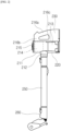
- FIG. 1 is a diagram to describe a vacuum cleaner system according to one embodiment.
- the vacuum cleaner system 1 may include a vacuum cleaner 200 and a vacuum cleaner 100.
- the vacuum cleaner system 1 may include the vacuum cleaner station 100.
- the vacuum cleaner 200 may be coupled to the vacuum cleaner station 100.
- the vacuum cleaner 2 may be coupled to a lateral surface of the vacuum cleaner station 100.
- the vacuum cleaner station 100 may be configured to remove dust inside a dust bin 220 of the vacuum cleaner 100.
- FIG. 2 is a schematic diagram showing the configuration of a vacuum cleaner according to one embodiment.
- FIG. 3 is a diagram of the vacuum cleaner shown in FIG. 2 , seen from a different angle.
- FIG. 4 is a diagram to describe a lower surface of a dust bin of the vacuum cleaner in the vacuum cleaner system according to one embodiment.
- forward may refer to the direction in which a suction part 212 is disposed with respect to a suction motor 214
- rearward may refer to the direction in which a handle 216 is disposed with respect to the suction motor 214.
- the direction on the right may be called rightward
- the direction on the left may be called leftward.
- upward and downward may be defined along the direction perpendicular to the ground when the lower surface of the dust bin 220 and the battery housing 230 are disposed on the floor.
- a virtual line penetrating the interior of the suction part 212 having the cylindrical shape may be formed.
- the dust separation part 213 may be in communication with the suction part 212.
- the dust separation part 213 may be configured to separate dust sucked inward through the suction part 212.
- the inner space of the dust separation unit 213 may be in communication with the inner space of the dust bin 220.
- the dust separation unit 213 may include at least one cyclone unit configured to dust by using cyclone flow.
- the inner space of the dust separation unit 213 may be in communication with the suction flow path. Accordingly, the air and dust sucked through the suction part 212 may spirally flow along an inner circumferential surface of the dust separation unit 213. Accordingly, cyclonic flow may occur in the inner space of the dust separation unit 213.
- the dust separation unit 213 may be in communication with the suction part 212, and may be the configuration to which the principle of a dust collector is applied to separate dust sucked into the vacuum cleaner body 210 through the suction part 212.
- the dust separation unit 213 may further include a secondary cyclone configured to secondarily separate dust from the air discharged from the cyclone.
- the secondary cyclone may be disposed inside the cyclone to maximize the size of the dust separation unit.
- the secondary cyclone may include a plurality of cyclone bodies disposed in parallel. The air discharged from the cyclone may dividedly pass through the plurality of cyclone bodies.
- the axis of the cyclone flow of the secondary cyclone may also be extended in a vertical direction, and the axis of the cyclone flow of the cyclone and the axis of the cyclone flow of the secondary cyclone may form a coaxial line in the vertical direction, which may be collectively referred to as the axis of the cyclone flow of the dust separation unit 213.
- the suction motor 214 may be configured to generate a suction force to suck in air.
- the suction motor 214 may be accommodated in the cleaner body housing 211.
- the suction motor 214 may generate the suction force, using rotation.
- the suction motor 214 may be provided in a cylinder-like shape.
- a virtual suction motor axial line may be formed by extending the rotation axis of the suction motor 214.
- the air discharge cover 215 may be provided on one axial side of the cleaner body housing 211.
- the air discharge cover 215 may communicate a filter for filtering air.
- the air discharge cover 215 may accommodate a HEPA filter.
- An air outlet hole may be formed in the air discharge cover 215 to discharge air sucked by the suction force.
- a flow guide may be disposed in the air discharge cover 215.
- the flow guide may be configured to guide the flow of air discharged through the air outlet hole.
- the handle 216 may be held by the user.
- the handle 216 may be disposed behind the suction motor 214.
- the handle 216 may be formed in a shape similar to a cylinder.
- the handle 216 may be formed in a curved cylinder shape.
- the handle 216 may be disposed at a predetermined angle with respect to the cleaner body housing 211, the suction motor 214, or the dust separation unit 213.
- the handle 216 may include a holding portion 216a formed in a cylindrical shape to be held by the user; a first extension 216b connected to one longitudinal (i.e., axial) end of the holding portion 216a and extending toward the suction motor 214; and a second extension 216c connected to the other longitudinal (i.e., axial) end of the holding portion 216a and extending toward the dust bin 220.
- the holding portion penetration line may be a virtual line formed inside the cylindrical handle 216, and may be a virtual line formed parallel to at least predetermined area of the outer surface of the holding portion 216a.
- the first extension may extend toward the cleaner body housing 211 or the suction motor 214. At least predetermined area of the first extension may extend in a horizontal direction.
- the second extension may extend toward the dust bin 220 from the holding portion 216a. At least predetermined area of the second extension may extend in a horizontal direction.
- the operation unit 218 may be disposed on the handle 216.
- the operation unit 218 may be disposed on an inclined surface formed on the top of the handle 216.
- the user may input an operation command or stop command for the vacuum cleaner 200 through the operation unit 218.
- the discharge cover 222 When the discharge cover 222 is closed, the lower surface of the dust bin 220 may be blocked (i.e., sealed) by the discharge cover 222 and the lower surface extension 221a.
- the dust bin 220 may include the dust bin compression lever 223 (see FIG. 8 ).
- the dust bin compression lever 223 may be disposed outside the dust bin 220 or the dust separation unit 213.
- the dust bin compression lever 223 may be disposed to be movable upward/downward outside the dust bin 220 or the dust separation unit 213.
- the dust bin compression lever 223 may be connected to the compressor (not shown). When the dust bin compression lever 223 is moved downward by the external force, the compressor (not shown) may be also moved downward together. This may provide the user with use convenience.
- the compressor (not shown) and the dust bin compression lever 223 may be restituted by an elastic member (not shown). Specifically, when the external force applied to the dust bin compression lever 223 is removed, the elastic member may move the dust bin compression lever 223 and the compressor (not shown) upward.
- the compressor (not shown) may be disposed inside the dust bin body 221.
- the compressor may be movable in the inner space of the dust bin body 221. Specifically, the compressor may be movable vertically inside the dust bin body 221. Through this, the compressor may compress dust inside the dust bin body 221 downward.
- the compressor may remove foreign substances such as residual dust in the dust bin 220 by moving to the bottom from the top. Through this, the suction force of the vacuum cleaner may be improved by preventing dust from remaining inside the dust bin 220. In addition, it is possible to eliminate bad smell caused by residue by preventing residual dust from remaining in the dust bin 220.
- the vacuum cleaner 200 may include the battery 240.
- the battery 240 may be configured to provide power to the suction motor 214.
- the battery 240 may be disposed under the handle 216.
- the battery 240 may be disposed behind the dust bin 220.
- the vacuum cleaner 200 may be coupled to a lateral surface of a housing 110.
- the cleaner body 210 of the vacuum cleaner 200 may be mounted to a mounting portion 120.
- the dust bin 220 of the vacuum cleaner 200 and the battery housing 230 may be coupled to a coupling surface 121, and an outer circumferential surface of the dust bin body 221 may be coupled to a dust bin guide surface 122.
- the suction part 212 may be coupled to a suction part guide surface 126 of the mounting portion 120.
- the central axis of the dust bin 220 may be disposed parallel to the ground, and the extension pipe 250 may be disposed along a direction perpendicular to the ground.
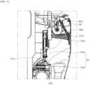
- FIG. 5 is a diagram to describe the inner structure of the vacuum cleaner station according to one embodiment.
- FIG. 6 is a diagram to describe a coupling portion provided in the vacuum cleaner station according to one embodiment.
- FIG. 7 is a perspective view to describe a fixing unit in the vacuum cleaner station according to one embodiment.
- FIGS. 8 and 9 are diagrams to describe the relationship between the vacuum cleaner and a door unit in the vacuum cleaner station according to one embodiment.
- FIG. 10 is a diagram to describe the relationship between the vacuum cleaner and a door unit in the vacuum cleaner station according to one embodiment.
- the bottom surface 111 may support the gravity-direction lower portion of the dust suction module 190. That is, the bottom surface 111 may support the lower portion of a dust collection motor 191 of the dust suction module 190.
- the outer wall surface 112 may include at least one surface.
- the outer wall surface 112 may include a first outer wall surface 112a, a second outer wall surface 112b, a third outer wall surface 112c, and a fourth outer wall surface 112d.
- the first outer wall surface 112a may be disposed on the front side of the vacuum cleaner station 100.
- the front side may mean the surface on which the vacuum cleaner 200 is exposed in a state where the vacuum cleaner 200 is coupled to the vacuum cleaner station 100. Accordingly, the first outer wall surface 112a may form the exterior of the front side of the vacuum cleaner station 100.
- the direction in which the suction motor 214 of the vacuum cleaner 200 is disposed may be called forward.
- the direction opposite to the direction in which the suction motor 214 of the vacuum cleaner station 100 is placed may be called rearward. Accordingly, the rear surface or rearward may mean the direction in which the second outer wall surface 112b is formed.
- the left side When looking at the front side based on the inner space of the housing 110, the left side may be called the left surface and the right side may be called the right surface. Accordingly, the rear surface may mean the direction in which the second outer wall surface 112b is formed.
- the left side When looking at the front surface with respect to the inner surface of the housing 110, the left side may be called the left surface and the right side may be called the right surface. Accordingly, the left surface may mean the direction in which the third outer wall surface 112c is formed, and the right surface may mean the direction in which the fourth outer wall surface 112d is formed.
- the first outer wall surface 112a may be a flat surface and it may be an entirely curved surface, or a surface having a partially curved area.
- the third outer wall surface 112c or the fourth outer wall surface 112d may be a flat surface and it may be a curved surface or a surface having a curved area.
- the top surface 113 may define the top exterior of the vacuum cleaner station. That is, the top surface 113 may means the surface disposed on the uppermost portion in the gravity direction within the vacuum cleaner station, and exposed to the outside.
- the top and bottom portion may mean the upper portion and the lower portion, respectively, along the direction of gravity (i.e., the direction perpendicular to the ground) when the vacuum cleaner station 100 is installed on the ground.
- the top surface 113 may be disposed parallel to the ground and also may be inclined at a predetermined angle with respect to the ground.
- a display unit may be disposed on the top surface 113.
- the display unit may be configured to display a state of the vacuum cleaner station 100, a state of the vacuum cleaner 200, and may also display information such as the cleaning progress and a map of the cleaning area.
- a bag accommodating space 115 may be formed within the housing 110.
- the bag accommodating space 115 may be placed below the gravity direction of the mounting portion 120 and above the gravity direction of the dust suction module 190.
- a dust collection unit 170 may be provided in the bag accommodating space 115.
- a bag supporting portion 173 which will be described later may be movably accommodated in the bag accommodating space 115.
- a dust bag cartridge 174 which will be described later may be detachably coupled to the bag accommodating space 115.
- a jointer 176 which will be described later may be mounted in the bag accommodating space 115.
- the bag accommodating space 115 may be in communication with a first flow path 181, a second flow path 182, and a bypass flow path 183, which will be described later. This configuration may provide the space in which the air and dust introduced from the dust bin 220 can flow and be collected in a dust bag 172.
- an axial line of the suction motor 214 may be perpendicular to the first outer wall surface 112a. That is, the axial line of the suction motor 214 may be formed parallel to the ground.
- a virtual line penetrating the dust bin 220 may be formed perpendicular to the first outer wall surface 112a.
- a longitudinal axis C of the housing 110 may be formed perpendicular to the ground.
- the longitudinal axis C of the housing 110 may be formed parallel to at least one of the first outer wall surface 112a, the second outer wall surface 112b, the third outer wall surface 112c, and the fourth outer wall surface 112d.
- the axis of the suction motor 214 may intersect the longitudinal axis of the vacuum cleaner station 100. That is, the rotation axis of the suction motor 214 may intersect the longitudinal axis of the vacuum cleaner station 100.
- the handle 216 may be disposed at a preset distance from the ground farther than a virtual line penetrating the dust bin 220.
- the convenience of being able to mount or demount the vacuum cleaner 200 to or from the vacuum cleaner station 100 may be provided by simply moving the vacuum cleaner 200 in a direction parallel to the ground.
- the vacuum cleaner station 100 may include the mounting portion 120 for coupling the vacuum cleaner 200.
- the mounting portion 120 may be disposed on the first outer wall surface 112a.
- the cleaner body 210, the dust bin 220, and the battery housing 230 of the vacuum cleaner 200 may be coupled to the mounting portion 120.
- the vacuum cleaner 200 may be coupled to the coupling surface 121.
- the coupling surface 121 may be in contact with the dust bin 220 of the vacuum cleaner 200 and the lower surface of the battery housing 230.
- the lower surface means the surface toward the ground when the user places the vacuum cleaner 200 on the ground.
- the mounting portion 120 may include a dust bin guide surface 122.
- the dust bin guide surface 122 may be disposed on the first outer wall surface 112a. the dust bin guide surface 122 may be connected to the first outer wall surface 112a. also, the dust bin guide surface 122 may be connected to the coupling surface 121.
- the protrusion moving hole 122a, the guide space 122b, the bypass hole 122c, and the first flow path 181 may form one flow path.
- the mounting portion 120 may include a guide protrusion 123.
- the guide protrusion 123 may be disposed on the coupling surface 121.
- the guide protrusion 123 may protrude upward from the coupling surface 121.
- Two guide protrusions 123 may be spaced apart a distance from each other. The distance between the two guide protrusions 123 may be corresponding to the width of the battery housing 230 of the vacuum cleaner 200. This may provide convenient coupling process of coupling the vacuum cleaner 200 to the coupling surface 121.
- the mounting sensor 125 may include a non-contact sensor.
- the mounting sensor 125 may include an IR sensor.
- the mounting sensor 125 may be disposed on the mounting portion lateral wall 124. Accordingly, when the dust bin 220 or the cleaner body 210 of the vacuum cleaner 200 passes the mounting portion lateral wall 124 and reaches the coupling surface 121, the mounting sensor 125 may sense the presence of the dust bin 220 or the cleaner body 210.
- the mounting sensor 125 may face the dust bin 220 of the vacuum cleaner 200 or the battery housing 230.
- the mounting portion 120 may include a suction part guide surface 126.
- the suction part guide surface 126 may be disposed on the first outer wall surface 112a.
- the suction part guide surface 126 may be connected to the dust bin guide surface 122.
- the suction part 212 may be coupled to the suction part guide surface 126.
- the shape of the suction part guide surface 126 may be corresponding to the shape of the suction part 212.
- the mounting portion 120 may further include a fixing member introduction hole 127.
- the fixing member introduction hole 127 may be formed in a shape of a long hole formed along the mounting portion lateral wall 124 so that the fixing member 131 can be introduced.
- the cleaner body 210 of the vacuum cleaner 200 may be stably mounted to the mounting portion 120 by the dust bin guide surface 122, the guide protrusion 123, and the suction part guide surface 126.
- the convenience of coupling the dust bin 220 of the vacuum cleaner 200 and the battery housing 230 to the coupling surface 121 may be provided.
- the vacuum cleaner station 100 may further include a charging unit 128.
- the charging unit 128 may be mounted on the mounting portion.
- the charging unit 128 may be electrically connected to the vacuum cleaner 200 mounted to the mounting portion 120.
- the charging unit 128 may be configured to supply power to the battery of the vacuum cleaner 200 mounted to the mounting portion 120.
- the vacuum cleaner station 100 may further include a side door (not shown).
- the side door may be disposed in the housing 110.
- the side door may selectively expose the dust collection unit 170 to the outside. Through this, the user can easily remove the dust bag 172 from the vacuum cleaner station 100.
- the fixing unit 130 according to the present disclosure will be described as follows.
- the vacuum cleaner 100 may include a fixing unit 130.
- the fixing unit 130 may be disposed on the mounting portion lateral wall 124. Alternatively, the fixing unit 130 may be disposed on the back surface of the coupling surface 121.
- the fixing unit 130 may be configured to fix the vacuum cleaner 200 coupled to the coupling surface 121. Specifically, the fixing unit 130 may fix the dust bin 220 and the battery housing 230 of the vacuum cleaner 200.
- the fixing unit 130 may include a fixing member 141 configured to fix the dust bin 220 and the battery housing 230 of the vacuum cleaner 200; and a fixing unit motor 133 configured to drive the fixing member 131.
- the fixing unit 130 may further include a fixing unit link 135 configured to transmit a power of the fixing unit motor 133 to the fixing member 131.
- the fixing member 131 may be disposed on the mounting portion lateral wall 124, and may be configured to reciprocate on the mounting portion lateral wall 124. Specifically, the fixing member 131 may be received inside the fixing member introduction hole 127.
- the fixing member 131 may be disposed on each of both sides of the mounting portion 120.
- two fixing members may be arranged in a pair symmetrically centered on the coupling surface 121.
- the fixing unit motor 133 may be configured to supply power for moving the fixing member 131.
- the fixing unit link 135 may be configured to convert the rotational force of the fixing motor 133 into reciprocating motion of the fixing member 131.
- a fixing sealer 136 may be disposed on the dust bin guide surface 122 to seal the dust bin 220 when the vacuum cleaner 200 is mounted. With this configuration, when the dust bin 220 of the vacuum cleaner 200 is coupled, the fixing sealer 136 may be pressurized by the weight of the vacuum cleaner 200, and the dust bin 220 and the dust bin guide surface 122 may be sealed.
- the fixing sealer 136 may be disposed on a virtual extension line of the fixing member 131. With this configuration, when the fixing unit motor 133 is operated and the fixing member 131 pressurizes the dust bin 220, the circumference of the dust bin at the same height may be sealed.
- the fixing sealer 136 may be disposed on the dust bin guide surface 122 in a bent line shape corresponding to arrangement of a cover opening unit 150, which will be described later.
- the fixing unit 130 may fix the cleaner body 210 of the vacuum cleaner 200.
- the fixing unit motor 133 may move the fixing member 131 and fix the cleaner body 210 of the vacuum cleaner 200.
- the suction force of the vacuum cleaner may be improved by preventing dust from remaining inside the dust bin.
- bad smell generated by residual dust may be removed by preventing dust from remaining inside the dust bin.
- the vacuum cleaner station 100 may include the door unit 140.
- the door unit 140 may be configured to open and close the dust passage hole 121a.
- the door unit 140 may include a door 141, a door motor 142, and a door arm 143.
- the door 141 may be hingedly coupled to the coupling surface 121 and configured to open and close the dust passage hole 121a.
- the door 141 may include a door main body 141a.
- the door main body 141a may be formed in a shape that can block the dust passage hole 121a.
- the door main body 141 may be formed in a shape similar to a disc.
- a hinge portion may be provided an upper portion of the door main body 141a and an arm coupling portion 141b may be disposed in a lower portion of the door main body 141a.
- the arm coupling portion 141b may be the means for rotatably coupling the door arm 143.
- the arm coupling portion 141b may be provided in a lower portion of the door main body 141a and rotatably coupled to the door main body 141a so that a door arm 143 can be rotatably coupled to the arm coupling portion 141b.
- the door motor 142 may be configured to provide a power to rotate the door 141.
- the door motor 142 may be configured to rotate the door arm 143 in a forward direction or reverse direction.
- the forward direction may mean a direction in which the door arm 143 pulls the door 141. Accordingly, when the door arm 143 is rotated in the forward direction, the dust passage hole 121a may be open.
- the reverse direction may mean a direction in which the door arm 143 pushes the door 141. Accordingly, when the door arm 143 is rotated in the reverse direction, at least some area of the dust passage hole 121a may be closed.
- the forward direction may be the opposite of the reverse direction.
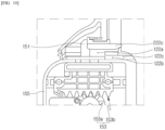
- the push protrusion 151 may be configured to linearly reciprocate so as to pressurize the coupling lever 222c. Specifically, the push protrusion 151 may be coupled to the gear box 155 so that its linear movement can be guided. The push protrusion 151 may be coupled to the cover opening gear 153 to be moved together along the movement of the cover opening gear 153.
- the cover opening sensor unit 155 may be provided in the gear box 155.
- the cover opening sensor unit 155f may include a contact sensor.
- the cover opening sensor unit 155f may include a micro switch.
- the cover opening sensor unit 155 may include a non-contact sensor.
- the cover opening sensor unit 155f may include an IR sensor.
- the cover opening unit 150 may allow the user to open the dust bin 220 without separately opening the discharge cover 222 of the vacuum cleaner, thereby improving user convenience.
- the discharge cover 222 may be opened in a state where the vacuum cleaner 200 is mounted to the vacuum cleaner station 100. Accordingly, there is an advantage of preventing dust from scattering.
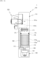
- FIGS. 11 to 16 are diagrams to describe the configuration and arrangement of the dust collection unit in the vacuum cleaner according to one embodiment of the present disclosure.
- the vacuum cleaner 100 may include the dust collection unit 170.
- the dust collection unit 170 may be provided in the housing 110.
- the dust collection unit 170 may be disposed in the bag accommodating space 115.
- the dust collection unit 170 may be disposed above of the dust collection motor 191 in the direction of gravity.
- the dust collection unit 170 may be configured to collect dust inside the dust bin 220 of the vacuum cleaner 200. Specifically, when the dust collection motor 191 is put into operation in a state where the vacuum cleaner 200 may be mounted to the vacuum cleaner station 100 and the inside of the dust bin 220 is in communication with the flow path unit 180, dust inside the dust bin 220 may flow along the flow path unit 180 to be collected in the dust collection unit 170.
- the dust separation part 171 may be configured to separate dust from the air introduced from the dust bin 220.
- the dust separation part 171 may be disposed above the dust bag 172, the bag support portion 173, the dust bag cartridge 174, and the jointer 176. That is, the dust bag cartridge 174, the bag support portion 173, the dust bag cartridge 174, and the jointer 176 may be disposed below the dust separation unit 172.
- the dust separation part 171 may be disposed on a longitudinal axial line C of the vacuum cleaner station 300.
- the dust separation part 171 may include a dust separation case 171a.
- a sealer may be provided on the lower surface of the dust separation part case 171a, and the sealer may come into contact with the dust bag cartridge 174.
- the sealer may be formed in a square shape surrounding the periphery of the dust passage pipe 171c.
- the cyclone unit 171b may include a cylindrical mesh.
- an axial direction of a mesh may be provided parallel to the ground.
- the dust separation part 171 may include a dust passage pipe 171c configured to guide the dust separated from the cyclone unit 171b to the dust bag 172.
- the dust passage pipe 171c may be formed downward from one axial side of the cyclone unit 171b. That is, the dust passage pipe 171c may be formed below the dust separation part case 171a. accordingly, the flow path formed in the dust passage pipe 171c may allow the dust bag cartridge 174 and the inner space of the bag support portion 173 to communicate with the cyclone unit 171b.
- the dust separation part 171 may further include a secondary cyclone configured to re-separate dust from the air discharged from the cyclone. At this time, the secondary cyclone may be provided inside the cyclone to minimize the size of the dust separation part 171.
- the dust bag 172 may be disposed within the housing 110, the dust bag 172 may be disposed under the dust separation part 171 in the direction of gravity.
- the bag support portion 173 may be disposed below the dust separation part 171. With this configuration, the dust separated in the dust separation part 171 may be collected within the bag support portion 173.
- the air inside the bag accommodating space 115 may be sucked into the dust collection motor 191 by the suction force of the dust collection motor 191, and a negative pressure for expanding the dust bag 172 may be formed in the bag accommodating space 115.
- a negative pressure may be applied toward the outside of the support main body 173a with respect to the dust bag 172, and the dust bag 172 may be expanded to become in close contact with the inner surface and lower surface of the support main body 173a. That is, the dust bag 172 may be expanded along the inner shape of the bag support portion 173.
- a uniform negative pressure may be applied to the entire dust bag 172 evenly, and the expanded state may be maintained.
- FIGS. 19 to 24 are diagrams to describe a process of pulling the bag suction portion 173 out from the vacuum cleaner station.
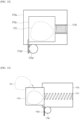
- a stopper 273d' as shown in FIGS. 22 and 23 may be provided in the support main body 173a and configured to linearly reciprocate.
- the stopper may contact the bag extracting portion 173c along the linear movement, to limit the movement of the bag extracting portion 173c.
- the stopper 173d' may be formed in a bar shape, with one side connected to a bag discharge actuator 173e', which will be described later, to move in a straight stroke when the bag discharge actuator 173e' is operated, and the other side provided to come into contact with the bag extracting portion 173c along the linear movement.
- the stopper 173d and 173d' may limit the movement of the bag extracting portion 173c by coming into contact with the bag extracting portion 173c, and release the movement limit of the bag extracting portion 173c as it is moved by the operation of the bag discharge actuator 173e and 173e'.
- the movement of the bag extracting 173c may be limited or the limit of the movement may be released.
- a spring 173f may provide an elastic force to the bag extracting portion 173c.
- the spring 173f may be a coil spring.
- one side of the spring 173f may be coupled to the support main body 173a, and the other side thereof may be coupled to the bag extracting portion 173c.
- the spring 173f may be in a state of being pressurized.
- the pressurizing of the spring 173f may be released and the bag extracting portion 173c may be pushed. Accordingly, the bag extracting portion 173c may be linearly moved by the spring 173f.
- Dust bag sensors 173g and 173h may be disposed in the bag support port 173 and may be configured to detect the dust bag 172.
- the dust bag sensors 173g and 173h may be disposed within the support main body 173a.
- the dust bag sensor 173g and 173h may be disposed, passing through the support main body 173a. With this configuration, the dust bag sensor 173g and 174h may be provided at a position allowing it to radiate light toward the dust bag 172 within the support main body 173a.
- the light emitting element (not show) may be configured to emit light. Specifically, the light emitting element may be disposed toward the inside of the support main body 173a, to emit light toward a direction toward the inside from the outside of the support main body 173a. The light emitted from the light emitting element may be reflected by the dust bag 172 and dust or foreign substances inside the dust bag 172.
- the light receiving element may be configured to receive light. Specifically, the light receiving light may receive the light reflected by the light emitting element.
- the light receiving element may be disposed toward the inside of the support main body 173a, like the light emitting element. Accordingly, the light receiving element may receive the light reflected by the dust bag 172 and dust or foreign substances inside the dust bag 172.
- the vacuum cleaner station may include a plurality of dust bag sensors 173g and 173h that are disposed at different heights, to determine whether the dust bag 172 is discharged or not.
- the dust bag sensors 173g and 173h may include a first dust bag sensor 173g and a second dust bag sensor 173h.
- the first dust bag sensor 173g and the second dust bag sensor 173h may be disposed in the support main body 173a. At this time, the first dust bag sensor 173g may be disposed farther from the ground than the second dust bag sensor 173h. That is, the second dust bag sensor 173h may be disposed below the first dust bag sensor 173g.
- the light irradiated by the first dust bag sensor 173g may reach the dust bag 172.
- the dust bag 172 is jointed and separated, and falling down from the dust bag cartridge 174, the light irradiated by the second dust bag sensor 173h may reach the dust bag 172.
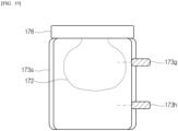
- the first dust bag sensor 173g may measure the amount of dust stored in the dust bag 172.
- the first dust bag sensor 173g may irradiate light toward the dust bag 172, and the amount of reflected light may be varied based on the amount of dust stored in the dust bag 172. Accordingly, the first dust bag sensor 173g may receive the light reflected by the dust bag 172 and the dust stored in the dust bag 172 and measure the amount of dust stored in the dust bag 172.
- the second dust bag 173h may sense presence of the dust bag 172.
- the second dust bag sensor 174h may irradiate light toward the dust bag 172 and the light may be reflected by the dust bag 172. Accordingly, the second dust bag sensor 173h may receive the light reflected by the dust bag 172 and sense whether the dust bag 172 is present or not.
- the first dust bag sensor 173g may sense the amount of dust inside the dust bag 172 in a state where the dust bag 172 is expanded.
- the second dust bag sensor 173h may sense whether the dust bag 172 is present below the bag support portion 173 after jointed and falling down.
- the dust bag may be easily supplied through the dust bag cartridge by the user's simply replacing the cartridge.
- the dust bag cartridge 174 may include the dust bag 172.
- the dust bag 172 may be coupled to the dust bag cartridge 174, and the dust bag 172 may be expanded toward the bag suction portion 173 as the dust collection motor 191 operates.
- Some area of the dust bag 172 may be separated from the dust bag cartridge 174 as the dust bag 172 is jointed along with the operation of the jointer 176 which will be descried later. With this configuration, the user does not have to separately tie up the dust bag having collected dust, thereby improving user convenience.
- the dust bag cartridge 174 may be disposed below the dust separation part 171. For example, an upper surface of the dust bag cartridge 174 may be in contact with a lower surface of the dust separation part 171.
- the dust bag cartridge 174 may define a space which will accommodate the dust bag 172. At this time, the dust bag cartridge 174 may be formed in a square pipe shape. That is, a space in which air can flow may be formed in (i.e., in a center area) the dust bag cartridge 174. At least predetermined area of the dust bag 172 may be expanded through the space.
- a hole may be formed in the dust bag cartridge 174 and the dust bag 172 can be extracted through the hole.
- the hole may be formed on an inner circumferential surface of the dust bag cartridge 174.
- the dust bag cartridge 174 may include at least one sealer to seal the gap in which dust could fly.
- the sealer may be provided on the upper surface of the dust bag cartridge 174. With this configuration, it is possible to prevent foreign substances from leaking between the dust bag cartridge 174 and the dust separation part 171.
- the sealer may be provided on the lower surface of the dust bag cartridge 174. With this configuration, it is possible to prevent foreign substances having passed the dust bag cartridge 174 from leaking between the dust bag cartridge 174 and the jointer 176.
- the dust collection unit 170 may further include the jointer 176.
- the jointer 176 may be disposed blow the dust bag cartridge 174.
- an upper surface of the jointer 176 may be in contact with a lower surface of the dust bag cartridge 174. With this configuration, the jointer 176 may guide the coupling or decoupling of the dust bag cartridge 174.
- the jointer 176 may be disposed above the bag suction portion 173.
- the lower surface of the jointer 176 may be in contact with the upper surface of the bag suction portion 173.
- the dust collected from the outside may be gathered in the roll vinyl and the roll vinyl may be automatically jointed. Accordingly, the user does not have to tie up the dust bag storing dust, thereby improving user convenience.
- a sealer may be disposed on the upper surface of the jointer 176 and come into contact with the dust bag cartridge 174.
- the sealer may be disposed in a square shape surrounding an outer area with respect to the flow path unit 180. The sealer may seal foreign substances from leaking between the jointer 176 and the dust bag cartridge 174.
- the vacuum cleaner station 100 may include the flow path unit 180.
- the flow path unit 180 may connect the vacuum cleaner 200 to the dust collection unit 170 and the dust collection motor 191.
- the flow path unit 180 may include a first flow path 181, a second flow path 182, and a bypass flow path 183.
- the first flow path 181 may be configured to connect the dust bin 220 of the vacuum cleaner 200 to the dust collection unit.
- the first flow path 181 may mean the space between the dust bin 220 of the vacuum cleaner 200 and the dust collection unit 170.
- the first flow path 181 may be the space formed toward the rear from the dust passage hole 121a, and may be a path formed downward from the dust passage hole 121a through which dust and air can flow.
- the second flow path 182 and the bypass flow path 183 may be in communication with each other to be collected to the dust suction module 190.
- the second flow path 182 may be connected to the bypass flow path 183.
- the bypass flow path 183 may be connected to the second flow path 182, and the second flow path 182 may be connected to the dust suction module 190.
- the second flow path 182 and the bypass flow path 183 may be connected to the dust collection unit 170 and the dust collection motor 191, respectively.
- the door opening/closing sensor unit 144 may transmit a signal indicating that the door 141 is opened, when the door 141 or the door arm 143 reaches a predetermined opening position DP1.
- the controller 400 may receive the signal indicating that the door 141 is opened from the door opening/closing sensor unit 137, and determined that the door 141 is opened.
- the controller 400 may stop the operation of the door motor 142 when determining that the door 141 is opened.
- the controller 400 may close the door 141 by rotating the door motor 142 in the reverse direction, when the emptying of the dust bin 220 is terminated.
- the controller 400 may operate the cover opening motor 152 and open the discharge cover 222 of the vacuum cleaner 200, when determining that the door 141 is opened.
- the controller 400 may drive the bag discharge motor 173e and move the stopper 173d. for example, while the stopper 173d and the bag extracting portion 173c are supported in contact, the controller 400 may drive the bag discharge motor 173e and move the stopper 173d in the direction in which the stopper 173d releases the contact with the bag extracting portion 173c.
- the controller 400 may operate the jointer 176, after the operation of the dust collection motor 191 is terminated.
- the controller 400 may operate the jointer 176 in a preset time after the operation of the dust collection motor 191 is terminated.
- the controller 400 may operate the jointer 176 in a preset time after the dust collection motor 191 is operated a preset number of times.
- the controller 400 may operate the jointer 176 at preset intervals, and when the dust collection motor 191 is operating, the controller 400 may operate the jointer 176 after a preset time period.
- the controller 400 may operate the jointer 176 when the amount of dust measured by the dust amount sensor (not shown) is more than a preset reference value.
- the controller 400 may be configured to suck dust inside the dust bin 220 by operating the dust collection motor 191.
- the controller 400 may operate the display 410 to display a state of emptying the dust bin and a state of charging the vacuum cleaner 200. For example, in this embodiment, if the amount of dust measured by the dust amount sensor is more than a preset reference value, the controller 400 may control the display 410 to display that it is necessary to replace the dust bag 172.
- the vacuum cleaner station 100 of the present disclosure may include the display 410.
- the display 410 may be disposed in the housing 110 or may be disposed in a separate display device. Also, it may be provided in a terminal including a mobile phone.
- the display 410 may include at least one of a display panel configured to output characters and/or figures, and a speaker configured to output voice signals and sounds. The user can easily figure out the state of the current process, the remaining time, etc. through the information output through the display.
- the vacuum cleaner station 100 may include a memory 430.
- the memory 430 may contain various data for driving and operating the vacuum cleaner station 100.
- the vacuum cleaner station 100 may include an input unit 440.
- the input unit 440 may be configured to generate key input data input by the user to control the operation of the vacuum cleaner station 100.
- the input unit 440 may include a key pad, a dome switch, a touchpad (static/capacitive), etc.
- the touch pad forms a mutual layer structure with the display unit 410, it can be called a touch screen.
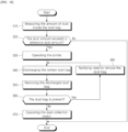
- FIG. 18 is a flow chart to describe a controlling method of the vacuum cleaner statin according to one embodiment.
- FIG. 19 is a schematic view to describe a process in which a first dust bag sensor measures the dust amount in the controlling method of the vacuum cleaner station according to one embodiment.
- FIG. 20 is a schematic view to describe a state where a jointed dust bag is accommodated in a bag discharge unit in the controlling method of the vacuum cleaner station according to one embodiment.
- FIG. 21 is a schematic view to describe a process of discharging the jointed dust bag through the movement of the bag discharge unit in the controlling method of the vacuum cleaner station according to one embodiment.
- FIG. 19 is a schematic view to describe a process in which a first dust bag sensor measures the dust amount in the controlling method of the vacuum cleaner station according to one embodiment.
- FIG. 20 is a schematic view to describe a state where a jointed dust bag is accommodated in a bag discharge unit in the controlling method of the vacuum cleaner station according to one embodiment.
- FIG. 21 is a schematic view to
- FIG. 22 is a schematic view to describe a state where a jointed dust bag is accommodated in a bag discharge unit in the controlling method of the vacuum cleaner station according to another embodiment.
- FIG. 23 is a schematic view to describe a process of discharging the jointed dust bag through the movement of the bag discharge unit in the controlling method of the vacuum cleaner station according to one embodiment.
- FIG. 24 is a schematic view to describe a process of detecting whether the jointed dust bag is present by using a second dust bag detecting sensor in the controlling method of the vacuum cleaner station according to one embodiment.
- the controller 400 may derive the amount of dust stored in the dust bag 172 based on the information received from the first dust bag sensor 173g.
- the memory 430 may store information about the amount of dust based on the light sensed by the first dust bag sensor 173g. Accordingly, the controller 400 may compute the amount of dust stored in the dust bag 172 based on the light sensed by the first dust bag sensor 173g.
- the controlling method of the vacuum cleaner station may include a bag joint step S30.
- the dust bag 172 may be jointed if the amount of dust stored in the dust bag 172 exceeds the preset reference dust amount.
Landscapes
- Engineering & Computer Science (AREA)
- Mechanical Engineering (AREA)
- Robotics (AREA)
- Electric Vacuum Cleaner (AREA)
- Filters For Electric Vacuum Cleaners (AREA)
Abstract
Description
- The present disclosure relates to a vacuum cleaner station and a controlling method thereof, more particularly, a vacuum cleaner station configured to separate dust contained in the air and collect it in a dust bag, and only allow user to empty the dust bag, and a controlling method thereof.
- Generally, a cleaner is an electrical appliance configured to suck in small pieces of trash or dust by sucking air and filling a dust bin provided therein, and is commonly called a vacuum cleaner.
- Such vacuum cleaners may be classified into manual cleaners that perform cleaning while the user moves the cleaner, and automatic cleaners that perform cleaning while driving on their own. The manual vacuum cleaners may be classified into canister type vacuum cleaners, upright type vacuum cleaners, handheld vacuum cleaners and stick type vacuum cleaners, depending on the shape
- In the past, canister-type vacuum cleaners were widely used for home vacuum cleaners, but recently, handheld vacuum cleaners stick type vacuum cleaners, which can a dust bin and vacuum cleaner body as one unit to improve convenience, are being widely used.
- A canister-type vacuum cleaner has a cleaner body and a suction inlet that are connected by a rubber hose or pipe, and in some cases, a brush may be fitted to the suction inlet for use.
- A handheld vacuum cleaner is designed to maximize portability. The handheld vacuum cleaner is light in weight but short in length, so the cleaning area may be limited when sitting down. Accordingly, it is used to clean localized areas such as a desk, sofa or inside a car.
- A stick vacuum cleaner may be used standing up so a user can clean without bending down. This makes the stick vacuum cleaner ideal for cleaning wide areas while moving around. While the handheld vacuum cleaner can clean narrow spaces, the stick vacuum cleaner can clean wider spaces and high places that are hard to reach. Recently, the stick vacuum cleaner is being provided in modular form, allowing user to actively change the vacuum cleaner type for user on various cleaning targets.
- In addition, robot vacuum cleaners configured to clean on their own without user manipulation are being used. A robot vacuum cleaner automatically cleans the cleaning target area by moving around the area on their own and sucking up foreign substances such as dust from the floor.
- However, conventional handheld vacuum cleaners, stick vacuum cleaners, and robot vacuum cleaners have small dust bins for storing collected dust, which is inconvenient for user to have to empty the dust bags every time.
- In addition, there is a problem that when the dust bin was emptied, dust is scattered and has a harmful effect on the user's health.
- In addition, there is another problem that the suction power of the vacuum cleaner is reduced when the remaining dust bin.
- In addition, there is a further problem that a bad smell occurs due to the residue if the remaining dust in the dust bin is not removed.
- As the prior art, Korean Patent Publication No.
KR2161708B1 - The prior art may include a station to which a dust bin of the vacuum cleaner is coupled, and the dust bag may be provided in the station. At this time, the dust bag may be mounted in a housing along a sliding groove and an outer surface of the dust bag may be formed of a material capable of filtering air while the air is passing therethrough.
- However, such a permeable or semi-permeable dust bag has a disadvantage that dust inside the dust bag might leak out of the dust bag and bad smells might also leak out of the dust bag.
- In addition, as the prior art, Korean Patent Publication No.
KR20210019940A - The prior art includes a vacuum cleaner sucking and storing dust contained in the air, a vacuum cleaner station coupled to a dust bin to empty the dust stored in the dust bin. The vacuum station may include a dust collection motor sucking foreign substances and air inside the dust bin coupled to the vacuum cleaner station, and a vinyl bag type dust collection unit.
- However, in the vacuum cleaner station, when the dust collection motor is operation, the vinyl bag might be pulled toward the dust collection motor only to be flattened.
- Accordingly, the inner space of the vinyl dust bag becomes narrower when the dust collection motor is operating, and it could be difficult to collect and capture dust inside the vinyl dust bag the vacuum cleaner station.
- In addition, the vacuum cleaner station might fail to measure the amount of dust inside the vinyl dust bag.
- Due to that, the above vacuum cleaner station might joint the vinyl dust back regardless of the amount of dust inside the dust bag, so the vinyl bag could be wasted while only a small amount of dust is store.
- Or, if the vinyl dust bag too full of dust is sealed, it might burst or the sealing might not be done properly. Due to that, dust might fly inside the vacuum cleaner station disadvantageously.
- In addition, even if the vinyl bag is jointed or bonded, there is a limit that the vinyl bag remains inside the vacuum cleaner station.
- Meanwhile, as the prior art, Korean Patent Publication No.
KR10-2021-0029583 - The vacuum cleaner includes a light-emitting element and a light-receiving element. The light-emitting element irradiates infrared rays into the dust bin, and the amount of dust may be determined through the voltage value output by the light-receiving element.
- However, the vacuum cleaner can determine only the dust amount inside the dust bin, and have the limitation of not being able to automatically empty the dust bin.
- Accordingly, one object of the present disclosure is to solve the above-noted disadvantages of the prior art, and to provide a vacuum cleaner station that may maintain the shape of a dust bag while collecting dust.
- Another object of the present disclosure is to provide a vacuum cleaner station that may separate dust from the air and collect it in a dust bag, while the air containing dust is flowing toward a dust collection motor.
- A further object of the present disclosure is to provide a vacuum cleaner station that does not require users to tie a dust bag themselves.
- A still further object of the present disclosure is to provide a vacuum cleaner station that may empty the dust bin by the user removing only dust bag.
- A still further object of the present disclosure is to provide a vacuum cleaner station that may measure the amount of dust collected in the dust bag.
- A still further object of the present disclosure is to provide a vacuum cleaner station that may remove the dust bag by automatically sealing the dust bag when the amount of dust collected in the dust bag is a predetermined reference amount or more.
- A still further object of the present disclosure is to provide a vacuum cleaner station that if the sealed dust bag is not discharged outside the vacuum cleaner station, may notify the user and allow the user to discharge the dust bag.
- To solve the objects of the present disclosure, a vacuum cleaner station may include a housing; a mounting portion disposed in the housing and comprising a coupling surface to which at least predetermined area of a vacuum cleaner is coupled; a dust collection unit accommodated within the housing and disposed below the mounting portion, the dust collection unit configured to collect dust inside a dust bin of the vacuum cleaner; and a dust collection motor accommodated within the housing and disposed below the dust collection unit, the dust collection motor configured to generate a suction force for sucking in dust inside the dust bin.
- At this time, the dust collection unit may include a dust bag configured to store dust; a bag support portion configured to accommodate the dust bag; and a dust bag sensor disposed in the bag support portion and configured to sense the dust bag.
- The dust bag sensor may include a first dust bag sensor configured to measure the amount of dust stored in the dust bag.
- The dust bag sensor may include a second dust bag sensor disposed closer to the ground than the first dust bag sensor and configured to sense presence of the dust bag.
- Meanwhile, the bag support portion may include a support main body; a bag extracting portion movably accommodated in the support main body and configured to transfer the dust bag.
- The bag support portion may further include a stopper configured to be supported on the bag extracting portion in contact, along with rotation.
- The bag support portion may further include a spring coupled to the support main body and the bag extracting portion, and configured to linearly move the bag extracting portion.
- The dust collection unit may further include a jointer configured to joint the dust bag; and a bag discharge actuator configured to apply a rotational force to the stopper, and the bag discharge actuator may be operated after the jointer is operated.
- To solve the objects of the present disclosure, a controlling method of a vacuum cleaner station coupled to a vacuum cleaner comprising a dust bin; and a discharge cover configured to selectively open and close the dust bin, and configured to collect dust inside the dust bin in a dust bag, the controlling method may include a dust amount sensing step of sensing the amount of dust stored in the dust bag; and a bag jointing step of jointing the dust bag when the amount of dust stored in the dust bag is more than a preset reference dust amount.
- The controlling method of the vacuum cleaner station may further include a bag discharging step of discharging the dust bag jointed in the bag jointing step.
- The controlling method of the vacuum cleaner station may further include a bag checking step of sensing whether the dust bag jointed in the bag jointing step is present.
- At this time, when it is sensed in the bag checking step that the jointed dust bag is removed, the dust bag may be expanded.
- When it is sensed in the bag checking step that the jointed dust bag is present, need to remove the dust bag may be displayed.
- The vacuum cleaner station according to the embodiments of the present disclosure has an effect of maintaining the shape of a dust bag while collecting dust.
- Furthermore, the vacuum cleaner station according to the embodiments of the present disclosure has an effect of separating dust from the air and collect it in a dust bag, while the air containing dust is flowing toward a dust collection motor.
- Still further, the vacuum cleaner station according to the embodiments of the present disclosure has an effect of sealing the dust bag without having to tie the dust bag directly by the jointer joining the upper portion of the dust bag.
- Still further, the vacuum cleaner station according to the embodiments of the present disclosure may have an effect of emptying the dust bin by the user removing only dust bag.
- Still further, the vacuum cleaner station according to the embodiments of the present disclosure may have an effect of measuring the amount of dust collected in the dust bag.
- Still further, the vacuum cleaner according to the embodiments may have an effect of removing the dust bag by automatically sealing the dust bag when the amount of dust collected in the dust bag is a predetermined reference amount or more.
- Still further, the vacuum cleaner may have an effect of discharging the sealed dust bag by notifying the user and allowing the user to discharge the dust bag if the sealed dust bag is not discharged outside the vacuum cleaner station.
-
-
FIG. 1 is a diagram to describe a vacuum cleaner system according to one embodiment; -
FIG. 2 is a schematic diagram showing the configuration of a vacuum cleaner according to one embodiment; -
FIG. 3 is a diagram of the vacuum cleaner shown inFIG. 2 , seen from a different angle; -
FIG. 4 is a diagram to describe a lower surface of a dust bin of the vacuum cleaner in the vacuum cleaner system according to one embodiment; -
FIG. 5 is a diagram to describe the inner structure of the vacuum cleaner station according to one embodiment; -
FIG. 6 is a diagram to describe a coupling portion provided in the vacuum cleaner station according to one embodiment; -
FIG. 7 is a perspective view to describe a fixing unit in the vacuum cleaner station according to one embodiment; -
FIGS. 8 and9 are diagrams to describe the relationship between the vacuum cleaner and a door unit in the vacuum cleaner station according to one embodiment; -
FIG. 10 is a diagram to describe the relationship between the vacuum cleaner and a door unit in the vacuum cleaner station according to one embodiment; -
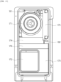
FIG. 11 is a diagram to describe the specific arrangement and configuration of a dust collection unit in the vacuum cleaner station according to one embodiment; -
FIG. 12 is a diagram to describe a process in which dust flows through a dust collection unit and a flow path unit in the vacuum cleaner station according to one embodiment; -
FIG. 13 is a front view to describe a dust collection unit in the vacuum cleaner station according to one embodiment; -
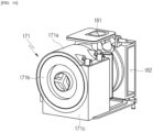
FIG. 14 is a perspective view to describe a dust separation unit in the vacuum cleaner station according to one embodiment; -
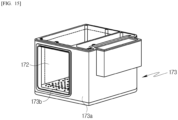
FIG. 15 is a perspective view to describe a bag support portion in the vacuum cleaner station according to one embodiment; -
FIG. 16 is a view to describe a flow path unit and a prefilter in the vacuum cleaner station according to one embodiment; -
FIG. 17 is a block view to describe the control configuration in the vacuum cleaner station according to one embodiment; -
FIG. 18 is a flow chart to describe a controlling method of the vacuum cleaner statin according to one embodiment; -
FIG. 19 is a schematic view to describe a process in which a first dust bag sensor measures the dust amount in the controlling method of the vacuum cleaner station according to one embodiment; -
FIG. 20 is a schematic view to describe a state where a jointed dust bag is accommodated in a bag discharge unit in the controlling method of the vacuum cleaner station according to one embodiment; -
FIG. 21 is a schematic view to describe a process of discharging the jointed dust bag through the movement of the bag discharge unit in the controlling method of the vacuum cleaner station according to one embodiment; -
FIG. 22 is a schematic view to describe a state where a jointed dust bag is accommodated in a bag discharge unit in the controlling method of the vacuum cleaner station according to another embodiment; -
FIG. 23 is a schematic view to describe a process of discharging the jointed dust bag through the movement of the bag discharge unit in the controlling method of the vacuum cleaner station according to one embodiment; and -
FIG. 24 is a schematic view to describe a process of detecting whether the jointed dust bag is present by using a second dust bag detecting sensor in the controlling method of the vacuum cleaner station according to one embodiment. - Description will now be given in detail according to exemplary embodiments disclosed herein, with reference to the accompanying drawings.
- The present disclosure may be variously modified and may have various embodiments, and particular embodiments illustrated in the drawings will be specifically described below. The description of the embodiments is not intended to limit the present disclosure to the particular embodiments, but it should be interpreted that the present disclosure is to cover all modifications, equivalents and alternatives falling within the spirit and technical scope of the present disclosure.
- Terminology that is used in the present disclosure is limited to only for embodiments herewith but made only to make it easy to understand the present disclosure.
- Terms of respective elements used in the following description are terms defined taking into consideration of the functions obtained in the present invention. Therefore, these terms do not limit technical elements in the present invention. Further, the defined terms of the respective elements will be called other terms in the art.
-
FIG. 1 is a diagram to describe a vacuum cleaner system according to one embodiment. - Referring to
FIG. 1 , thevacuum cleaner system 1 according to the embodiment of the present disclosure may include avacuum cleaner 200 and avacuum cleaner 100. - The
vacuum cleaner system 1 may include thevacuum cleaner station 100. Thevacuum cleaner 200 may be coupled to thevacuum cleaner station 100. The vacuum cleaner 2 may be coupled to a lateral surface of thevacuum cleaner station 100. Thevacuum cleaner station 100 may be configured to remove dust inside adust bin 220 of thevacuum cleaner 100. -
FIG. 2 is a schematic diagram showing the configuration of a vacuum cleaner according to one embodiment.FIG. 3 is a diagram of the vacuum cleaner shown inFIG. 2 , seen from a different angle.FIG. 4 is a diagram to describe a lower surface of a dust bin of the vacuum cleaner in the vacuum cleaner system according to one embodiment. - First, referring to
FIGS. 2 to 4 , the structure of thevacuum cleaner 200 will be described as follows. - The
vacuum cleaner 200 may mean a vacuum cleaner that is manually operated by a user. For example, thevacuum cleaner 200 may mean a handheld vacuum cleaner or a still vacuum cleaner. - The
vacuum cleaner 200 may be mounted on thevacuum cleaner station 100. Thevacuum cleaner 200 can be supported by thevacuum cleaner station 100. Thevacuum cleaner 200 may be coupled to thevacuum cleaner station 100. - Meanwhile, in one embodiment, the direction of the
vacuum cleaner 200 may be defined based on the time when thedust bin 220 and a lower surface of abattery housing 230 are placed on the floor. - At this time, forward may refer to the direction in which a
suction part 212 is disposed with respect to a suction motor 214, and rearward may refer to the direction in which ahandle 216 is disposed with respect to the suction motor 214. When looking at thesuction part 212 from the suction motor 214, the direction on the right may be called rightward, and the direction on the left may be called leftward. In addition, upward and downward may be defined along the direction perpendicular to the ground when the lower surface of thedust bin 220 and thebattery housing 230 are disposed on the floor. - The
vacuum cleaner 200 may include a cleaner body 210. The cleaner body 210 may include acleaner body housing 211, asuction part 212, adust separation part 213, a suction motor 214, an air discharge cover 215, ahandle 216, and anoperation unit 218. - The
cleaner body housing 211 may define the exterior of thevacuum cleaner 200. Thecleaner body housing 211 may provide a space that can accommodate the suction motor 214 and a filter (not shown). Thecleaner body housing 211 may be provided in a shape similar to a cylinder. - The
suction part 212 may protrude outward from thecleaner body housing 211. For example, thesuction part 212 may be formed in a cylindrical shape with an open inside. Thesuction part 212 may be coupled to anextension pipe 240. Thesuction part 212 may provide a flow path through which air containing dust can flow (hereinafter, a suction flow path). - Meanwhile, a virtual line penetrating the interior of the
suction part 212 having the cylindrical shape may be formed. - First, the
dust separation part 213 may be in communication with thesuction part 212. Thedust separation part 213 may be configured to separate dust sucked inward through thesuction part 212. The inner space of thedust separation unit 213 may be in communication with the inner space of thedust bin 220. - For example, the
dust separation unit 213 may include at least one cyclone unit configured to dust by using cyclone flow. The inner space of thedust separation unit 213 may be in communication with the suction flow path. Accordingly, the air and dust sucked through thesuction part 212 may spirally flow along an inner circumferential surface of thedust separation unit 213. Accordingly, cyclonic flow may occur in the inner space of thedust separation unit 213. - The
dust separation unit 213 may be in communication with thesuction part 212, and may be the configuration to which the principle of a dust collector is applied to separate dust sucked into the vacuum cleaner body 210 through thesuction part 212. - The
dust separation unit 213 may further include a secondary cyclone configured to secondarily separate dust from the air discharged from the cyclone. At this time, the secondary cyclone may be disposed inside the cyclone to maximize the size of the dust separation unit. The secondary cyclone may include a plurality of cyclone bodies disposed in parallel. The air discharged from the cyclone may dividedly pass through the plurality of cyclone bodies. - At this time, the axis of the cyclone flow of the secondary cyclone may also be extended in a vertical direction, and the axis of the cyclone flow of the cyclone and the axis of the cyclone flow of the secondary cyclone may form a coaxial line in the vertical direction, which may be collectively referred to as the axis of the cyclone flow of the
dust separation unit 213. - The suction motor 214 may be configured to generate a suction force to suck in air. The suction motor 214 may be accommodated in the
cleaner body housing 211. The suction motor 214 may generate the suction force, using rotation. As one example, the suction motor 214 may be provided in a cylinder-like shape. - Meanwhile, in this embodiment, a virtual suction motor axial line may be formed by extending the rotation axis of the suction motor 214.
- The air discharge cover 215 may be provided on one axial side of the
cleaner body housing 211. The air discharge cover 215 may communicate a filter for filtering air. As one example, the air discharge cover 215 may accommodate a HEPA filter. - An air outlet hole may be formed in the air discharge cover 215 to discharge air sucked by the suction force.
- A flow guide may be disposed in the air discharge cover 215. The flow guide may be configured to guide the flow of air discharged through the air outlet hole.
- The
handle 216 may be held by the user. Thehandle 216 may be disposed behind the suction motor 214. As one example, thehandle 216 may be formed in a shape similar to a cylinder. Alternatively, thehandle 216 may be formed in a curved cylinder shape. Thehandle 216 may be disposed at a predetermined angle with respect to thecleaner body housing 211, the suction motor 214, or thedust separation unit 213. - The
handle 216 may include a holdingportion 216a formed in a cylindrical shape to be held by the user; afirst extension 216b connected to one longitudinal (i.e., axial) end of the holdingportion 216a and extending toward the suction motor 214; and asecond extension 216c connected to the other longitudinal (i.e., axial) end of the holdingportion 216a and extending toward thedust bin 220. - Meanwhile, in this embodiment, a virtual line penetrating the holding
portion 216a may be formed by extending along the longitudinal direction of the holdingportion 216a (i.e., the axial direction of the cylindrical shape). - For example, the holding portion penetration line may be a virtual line formed inside the
cylindrical handle 216, and may be a virtual line formed parallel to at least predetermined area of the outer surface of the holdingportion 216a. - The upper surface of the
handle 216 may define the exterior of some area of the upper surface of thevacuum cleaner 200. Through this, it is possible to prevent the components of thevacuum cleaner 200 from coming into contact with the user's arm when the user holds thehandle 216. - The first extension may extend toward the
cleaner body housing 211 or the suction motor 214. At least predetermined area of the first extension may extend in a horizontal direction. - The second extension may extend toward the
dust bin 220 from the holdingportion 216a. At least predetermined area of the second extension may extend in a horizontal direction. - The
operation unit 218 may be disposed on thehandle 216. Theoperation unit 218 may be disposed on an inclined surface formed on the top of thehandle 216. The user may input an operation command or stop command for thevacuum cleaner 200 through theoperation unit 218. - The
vacuum cleaner 200 may include thedust bin 220. Thedust bin 220 may be in communication with thedust separation unit 213. Thedust bin 220 may be configured to store dust separated from thedust separation unit 213. - The
dust bin 220 may include adust bin body 221, adischarge cover 222, a dustbin compression lever 223, and a compressor (not shown). - The
dust bin body 221 may provide a predetermined space for storing dust separated from thedust separation unit 213. For example, thebust bin body 221 may be formed in a shape similar to a cylinder. - Meanwhile, in this embodiment, a virtual dust bin penetration line may be formed by penetrating the inner space of the
dust bin body 221 and extending along the longitudinal direction (i.e., the axial direction in the cylindricaldust bin body 221. - A lower surface (i.e., bottom surface) of the
dust bin body 221 may be partially open. Also, alower surface extension 221a may be formed on the lower surface (i.e., bottom surface) of thedust bin body 221. Thelower surface extension 221a may be formed block some area of the lower surface of thedust bin body 221. - The
dust bin 220 may include thedischarge cover 222. Thedischarge cover 222 may be disposed on the lower surface of thedust bin 220. - The
discharge cover 220 may be configured to open and close one longitudinal end of thedust bin body 221. Specifically, thedischarge cover 222 may selectively open and close the bottom of thedust bin 220 which is opened downward. - The
discharge cover 222 may include acover body 222a and ahinge portion 222b. thecover body 222a may be configured to partially block the lower surface of the dust bin body 2221. Thecover body 222a may be rotatable downward with respect to thehinge portion 222b. Thehinge portion 222b may include a torsion spring 22b. Accordingly, when the discharge cover 22 is separated from thedust bin body 221, thecover body 222a may be supported in a state of being rotated at a predetermined angle or more with respect to thehinge portion 222b in thedust bin body 221 by the elastic force of thetorsion spring 222d. - The
discharge cover 222 may be coupled to thedust bin 220 through hook coupling. Meanwhile, thedischarge cover 222 may be separated from thedust bin 220 through acoupling lever 222c. specifically, thecoupling lever 222c may be disposed on a front outer surface of thedust bin 220. When an external force is applied, thecoupling lever 222c may elastically deform a hook formed by extending from thecover body 222a to release the hook-coupling between thecover body 222a and thedust bin body 221. - When the
discharge cover 222 is closed, the lower surface of thedust bin 220 may be blocked (i.e., sealed) by thedischarge cover 222 and thelower surface extension 221a. - The
dust bin 220 may include the dust bin compression lever 223 (seeFIG. 8 ). The dustbin compression lever 223 may be disposed outside thedust bin 220 or thedust separation unit 213. The dustbin compression lever 223 may be disposed to be movable upward/downward outside thedust bin 220 or thedust separation unit 213. The dustbin compression lever 223 may be connected to the compressor (not shown). When the dustbin compression lever 223 is moved downward by the external force, the compressor (not shown) may be also moved downward together. This may provide the user with use convenience. The compressor (not shown) and the dustbin compression lever 223 may be restituted by an elastic member (not shown). Specifically, when the external force applied to the dustbin compression lever 223 is removed, the elastic member may move the dustbin compression lever 223 and the compressor (not shown) upward. - The compressor (not shown) may be disposed inside the
dust bin body 221. The compressor may be movable in the inner space of thedust bin body 221. Specifically, the compressor may be movable vertically inside thedust bin body 221. Through this, the compressor may compress dust inside thedust bin body 221 downward. In addition, when thedischarge cover 222 is separated only to open the bottom of thedust bin 220, the compressor may remove foreign substances such as residual dust in thedust bin 220 by moving to the bottom from the top. Through this, the suction force of the vacuum cleaner may be improved by preventing dust from remaining inside thedust bin 220. In addition, it is possible to eliminate bad smell caused by residue by preventing residual dust from remaining in thedust bin 220. - The
vacuum cleaner 200 may include abattery housing 230. Thebattery housing 230 may accommodate thebattery 240. Thebattery housing 230 may be disposed under thehandle 216. For example, thebattery housing 230 may have a hexahedral shape with an open bottom. The rear of thebattery housing 230 may be connected to thehandle 216. - The
battery housing 230 may include an accommodating portion that is open downward. Thebattery 240 may be mounted or demounted through the accommodating portion of thebattery housing 230. - The
vacuum cleaner 200 may include thebattery 240. - For example, the
battery 240 may be detachably connected to thevacuum cleaner 200. Thebattery 240 may be detachably mounted to thebattery housing 230. For example, thebattery 240 may be inserted into thebattery housing 230 from the lower portion of thebattery housing 230. With this configuration, the portability of thevacuum cleaner 200 can be improved. - Alternatively, the
battery 240 may be integrally formed within thebattery housing 230. At this time, the lower surface of thebattery 240 may not be exposed to the outside. - The
battery 240 may be configured to provide power to the suction motor 214. Thebattery 240 may be disposed under thehandle 216. Thebattery 240 may be disposed behind thedust bin 220. - According to the embodiment, when the
battery 240 is mounted in thebattery housing 230, the lower surface of thebattery 240 may be exposed to the outside. When thevacuum cleaner 200 is put down on the floor, thebattery 240 may be placed on the floor, so thebattery 240 can be demounted form thebattery housing 230. In addition, the lower surface of thebattery 240 may be exposed to the outside and may then directly come into contact with external air of thebattery 240, thereby improving the cooling performance of thebattery 240. - Meanwhile, if the
battery 240 is integrally formed in thebattery housing 230 as one body, the structure configured for the connection between thebattery 240 and thebattery housing 230 may be reduced, thereby reducing the overall size of thevacuum cleaner 200 and the weight of thevacuum cleaner 200. - The
vacuum cleaner 200 may include theextension pipe 250. The extension pipe may be in communication with acleaning module 260. Theextension pipe 250 may be in communication with the cleaner body 210. Theextension pipe 250 may be in communication with thesuction part 212 of the cleaner body 210. Theextension pipe 250 may be formed in a long cylindrical shape. - The cleaner body 210 may be connected with the
extension pipe 250. The cleaner body 210 may be connected to thecleaning module 260 through theextension pipe 250. The cleaner body 210 may be configured to generate a suction force by using the suction motor 214, and provide the suction force to thecleaning module 260 through theextension pipe 250. Dust may be introduced into the cleaner body 210 through thecleaning module 260 and theextension pipe 250. - The
vacuum cleaner 200 may include thecleaning module 260. Thecleaning module 260 may be in communication with theextension pipe 250. Accordingly, external air may pass through thecleaning module 260 and theextension pipe 250 and may be introduced into the cleaner body 210 of thevacuum cleaner 200 by the suction force generated in the cleaner body 210 of thevacuum cleaner 200. - Dust inside the
dust bin 220 of thevacuum cleaner 200 may be collected in adust collection unit 170 of thevacuum cleaner station 200 by the gravity and the suction force of adust collection motor 191. Through this, user convenience may be provided by removing dust inside the dust bin without the user's separate operation. In addition, this may eliminate the inconvenience of the user having to empty the dust bin every time. Also, this can prevent dust from flying when the dust bin is emptied. - The
vacuum cleaner 200 may be coupled to a lateral surface of ahousing 110. Specifically, the cleaner body 210 of thevacuum cleaner 200 may be mounted to a mountingportion 120. More specifically, thedust bin 220 of thevacuum cleaner 200 and thebattery housing 230 may be coupled to acoupling surface 121, and an outer circumferential surface of thedust bin body 221 may be coupled to a dustbin guide surface 122. Thesuction part 212 may be coupled to a suctionpart guide surface 126 of the mountingportion 120. In this instance, the central axis of thedust bin 220 may be disposed parallel to the ground, and theextension pipe 250 may be disposed along a direction perpendicular to the ground. -
FIG. 5 is a diagram to describe the inner structure of the vacuum cleaner station according to one embodiment.FIG. 6 is a diagram to describe a coupling portion provided in the vacuum cleaner station according to one embodiment.FIG. 7 is a perspective view to describe a fixing unit in the vacuum cleaner station according to one embodiment.FIGS. 8 and9 are diagrams to describe the relationship between the vacuum cleaner and a door unit in the vacuum cleaner station according to one embodiment.FIG. 10 is a diagram to describe the relationship between the vacuum cleaner and a door unit in the vacuum cleaner station according to one embodiment. - Referring to
FIGS. 5 to 10 , thevacuum cleaner station 100 according to the present disclosure will be described as follows. - The
vacuum cleaner 200 may be connected to thevacuum cleaner station 100. Specifically, the cleaner body of thevacuum cleaner 200 may be coupled to the lateral surface of thevacuum cleaner station 100. Thevacuum cleaner station 100 may be configured to remove dust inside the dust bin of thevacuum cleaner 200. - The
vacuum cleaner station 100 may include thehousing 110. Thehousing 110 may define the exterior of thevacuum cleaner station 100. Specifically, thehousing 110 may be formed in a cylindrical shape having at least one outer wall surface. For example, thehousing 110 may be formed in a shape similar to a square pillar. - The
housing 110 may have an inner space formed to accommodate thedust collection unit 170 configured to store dust therein and adust suction module 190 configured to generate a flow force for collecting dust in thedust collection unit 170. - The
housing 110 may include abottom surface 111, anouter wall surface 112, and a tosurface 113. - The
bottom surface 111 may support the gravity-direction lower portion of thedust suction module 190. That is, thebottom surface 111 may support the lower portion of adust collection motor 191 of thedust suction module 190. - At this time, the
bottom surface 111 may be disposed toward the ground. It Thebottom surface 111 may be disposed parallel to the ground, but also be disposed at a predetermined angle relative to the ground. This configuration has an advantage of stably supporting thedust collection motor 191 and balancing the overall weight even when thevacuum cleaner 200 is connected. - Meanwhile, according to the embodiment, the
bottom surface 111 may further include ground supporting portion 311a configured increase the area in contact with the ground in order to prevent thevacuum cleaner station 100 from falling over and maintain balance. For example, the ground supporting portion 311a may have a plate-shaped member formed by extending from thebottom surface 111, and one or more frames may protrude and extend along the ground direction from thebottom surface 111. - The
outer wall surface 112 may mean a surface formed along the gravity direction, and may mean a surface connected to thebottom surface 111. For example, theouter wall surface 111 may mean a surface perpendicularly connected to thebottom surface 111. Alternatively, theouter wall surface 112 may be arranged to be inclined at a predetermined angle with respect to thebottom surface 111. - The
outer wall surface 112 may include at least one surface. For example, theouter wall surface 112 may include a firstouter wall surface 112a, a second outer wall surface 112b, a thirdouter wall surface 112c, and a fourth outer wall surface 112d. - At this time, in this embodiment, the first
outer wall surface 112a may be disposed on the front side of thevacuum cleaner station 100. Here, the front side may mean the surface on which thevacuum cleaner 200 is exposed in a state where thevacuum cleaner 200 is coupled to thevacuum cleaner station 100. Accordingly, the firstouter wall surface 112a may form the exterior of the front side of thevacuum cleaner station 100. - Meanwhile, in order to understand this embodiment, the direction is defined as follows. In this embodiment, the direction may be defined as the direction in a state where the
vacuum cleaner 200 is placed on thevacuum cleaner station 100. - When the
vacuum cleaner 200 is mounted on thevacuum cleaner station 100, the direction in which thevacuum cleaner 200 is exposed to the outside of thevacuum cleaner station 100 may be called the front direction. - In another aspect, when the
vacuum cleaner 200 is mounted on thevacuum cleaner station 100, the direction in which the suction motor 214 of thevacuum cleaner 200 is disposed may be called forward. The direction opposite to the direction in which the suction motor 214 of thevacuum cleaner station 100 is placed may be called rearward. Accordingly, the rear surface or rearward may mean the direction in which the second outer wall surface 112b is formed. - When looking at the front side based on the inner space of the
housing 110, the left side may be called the left surface and the right side may be called the right surface. Accordingly, the rear surface may mean the direction in which the second outer wall surface 112b is formed. - When looking at the front surface with respect to the inner surface of the
housing 110, the left side may be called the left surface and the right side may be called the right surface. Accordingly, the left surface may mean the direction in which the thirdouter wall surface 112c is formed, and the right surface may mean the direction in which the fourth outer wall surface 112d is formed. - The first
outer wall surface 112a may be a flat surface and it may be an entirely curved surface, or a surface having a partially curved area. - The mounting
portion 120 may be disposed on the firstouter wall surface 112a. With this configuration, thevacuum cleaner 200 may be mounted to thevacuum cleaner station 100, and may be supported by thevacuum cleaner station 100. The detailed configuration of the mountingportion 120 will be described later. - Meanwhile, it is also possible to add a structure formed in various types to the first
outer wall surface 112a so as to mount thecleaning module 260. - In this embodiment, the second outer wall surface 112b may be a surface facing the first
outer wall surface 112a. That is, the second outer wall surface 112b may be disposed on a rear surface of thevacuum cleaner 100. The second outer wall surface 112b may define the exterior of the rear surface of thevacuum cleaner station 100. - In this embodiment, the third
outer wall surface 112c and the fourth outer wall surface 112d may refer to the surfaces connecting the firstouter wall surface 112a and the second outer wall surface 112b. at this time, the thirdouter wall surface 112c may be disposed on the left surface of thevacuum cleaner station 100, and the fourth outer wall surface 112d may be disposed on the right surface of thevacuum cleaner station 100. Alternatively, the thirdouter wall surface 112c may be disposed on the right surface of thevacuum cleaner station 100, and the fourth outer wall surface 112d may be disposed on the left surface of thevacuum cleaner station 100. - The third
outer wall surface 112c or the fourth outer wall surface 112d may be a flat surface and it may be a curved surface or a surface having a curved area. - Meanwhile, it is also possible to add a structure formed in various types to the third
outer wall surface 112c or the fourth outer wall surface 112d so as to mount thecleaning module 260. - The
top surface 113 may define the top exterior of the vacuum cleaner station. That is, thetop surface 113 may means the surface disposed on the uppermost portion in the gravity direction within the vacuum cleaner station, and exposed to the outside. - For reference, in this embodiment, the top and bottom portion may mean the upper portion and the lower portion, respectively, along the direction of gravity (i.e., the direction perpendicular to the ground) when the
vacuum cleaner station 100 is installed on the ground. - At this time, the
top surface 113 may be disposed parallel to the ground and also may be inclined at a predetermined angle with respect to the ground. - A display unit may be disposed on the
top surface 113. The display unit may be configured to display a state of thevacuum cleaner station 100, a state of thevacuum cleaner 200, and may also display information such as the cleaning progress and a map of the cleaning area. - Meanwhile, according to the embodiment, the
top surface 113 may be separable from theouter wall surface 112. At this time, when thetop surface 113 is separated, the battery separated from thevacuum cleaner 200 may be disposed in the inner space surrounded by theouter wall surface 112 and a terminal (not shown) configured to charge the separated battery may be provided therein. - Meanwhile, a bag
accommodating space 115 may be formed within thehousing 110. The bagaccommodating space 115 may be placed below the gravity direction of the mountingportion 120 and above the gravity direction of thedust suction module 190. - A
dust collection unit 170 may be provided in the bagaccommodating space 115. Specifically, abag supporting portion 173 which will be described later may be movably accommodated in the bagaccommodating space 115. Adust bag cartridge 174 which will be described later may be detachably coupled to the bagaccommodating space 115. Ajointer 176 which will be described later may be mounted in the bagaccommodating space 115. The bagaccommodating space 115 may be in communication with afirst flow path 181, asecond flow path 182, and abypass flow path 183, which will be described later. This configuration may provide the space in which the air and dust introduced from thedust bin 220 can flow and be collected in adust bag 172. - In the present disclosure, the
vacuum cleaner 200 may be mounted to the outer wall surface of thevacuum cleaner station 100. For example, thedust bin 220 of thevacuum cleaner 200 and thebattery housing 230 may be coupled to thecoupling surface 121 of thevacuum cleaner station 100. That is, thevacuum cleaner 200 may be mounted on the firstouter wall surface 112a. - At this time, an axial line of the suction motor 214 may be perpendicular to the first
outer wall surface 112a. That is, the axial line of the suction motor 214 may be formed parallel to the ground. - A virtual line penetrating the
dust bin 220 may be formed perpendicular to the firstouter wall surface 112a. - A longitudinal axis C of the
housing 110 may be formed perpendicular to the ground. The longitudinal axis C of thehousing 110 may be formed parallel to at least one of the firstouter wall surface 112a, the second outer wall surface 112b, the thirdouter wall surface 112c, and the fourth outer wall surface 112d. - When the
vacuum cleaner 200 is mounted to thevacuum cleaner station 100, the axis of the suction motor 214 may intersect the longitudinal axis of thevacuum cleaner station 100. That is, the rotation axis of the suction motor 214 may intersect the longitudinal axis of thevacuum cleaner station 100. - When the
vacuum cleaner 200 is mounted to the vacuum cleaner station100, thebattery 240 may be placed at a distance from the ground farther than the rotation axis of the suction motor 214. With this configuration, thevacuum cleaner 200 may be stably supported on thevacuum cleaner station 100. - When the
vacuum cleaner 200 is mounted to thevacuum cleaner station 100, a virtual line penetrating thedust bin 220 may intersect the longitudinal axis of thevacuum cleaner station 100. That is, the longitudinal axis of thedust bin 220 may intersect the longitudinal axis of thevacuum cleaner station 100. At this time, the intersection of the longitudinal axis of thedust bin 220 and the longitudinal axis of thevacuum cleaner station 100 may be located inside thehousing 110, and more specifically, inside theflow path unit 180. - Meanwhile, when the
vacuum cleaner 100 is mounted to thevacuum cleaner station 100, thehandle 216 may be disposed at a preset distance from the ground farther than a virtual line penetrating thedust bin 220. With this configuration, when the user holds thehandle 216, the convenience of being able to mount or demount thevacuum cleaner 200 to or from thevacuum cleaner station 100 may be provided by simply moving thevacuum cleaner 200 in a direction parallel to the ground. - Referring to
FIG. 6 , the mountingportion 120 of thevacuum cleaner station 100 according to the present disclosure will be described as follows. - The
vacuum cleaner station 100 may include the mountingportion 120 for coupling thevacuum cleaner 200. Specifically, the mountingportion 120 may be disposed on the firstouter wall surface 112a. The cleaner body 210, thedust bin 220, and thebattery housing 230 of thevacuum cleaner 200 may be coupled to the mountingportion 120. - The mounting
portion 120 may include acoupling surface 121. Thecoupling surface 121 may be disposed on a lateral surface of thehousing 110. For example, thecoupling surface 121 may be a groove-shaped surface recessed inwardly from the firstouter wall surface 112a toward the inside of thevacuum cleaner station 100. That is, thecoupling surface 121 may mean a surface forming a step with the firstouter wall surface 112a. - The
vacuum cleaner 200 may be coupled to thecoupling surface 121. For example, thecoupling surface 121 may be in contact with thedust bin 220 of thevacuum cleaner 200 and the lower surface of thebattery housing 230. Here, the lower surface means the surface toward the ground when the user places thevacuum cleaner 200 on the ground. - For example, the angle formed by the
coupling surface 121 with the ground may be a right angle. Through this, the space of thevacuum cleaner station 100 may be minimized when thevacuum cleaner 200 is coupled to thecoupling surface 121. - As another example, the
coupling surface 121 may be disposed at a predetermined angle with respect to the ground. Through this, when thevacuum cleaner 200 is coupled to thecoupling surface 121, thevacuum cleaner station 100 may be stably supported. - A
dust passage hole 121a may be formed in thecoupling surface 121 to introduce external air into thehousing 110. Thedust passage hole 121a may be formed in a hole shape corresponding to the shape of thedust bin 220 so that dust inside thedust bin 220 can be introduced into thedust collection unit 170. Thedust bin 220 and thehole 121a may be formed to in a shape corresponding to the shape of thedischarge cover 222 of thedust bin 220. Thedust passage hole 121a may be formed be in communication with theflow path unit 180 which will be described later. - The mounting
portion 120 may include a dustbin guide surface 122. The dustbin guide surface 122 may be disposed on the firstouter wall surface 112a. the dustbin guide surface 122 may be connected to the first outer wall surface 112a. also, the dustbin guide surface 122 may be connected to thecoupling surface 121. - The dust
bin guide surface 122 may be formed in a shape corresponding to the outer surface of thedust bin 220. A front outer surface of thedust bin 220 may be coupled to the dustbin guide surface 122. This may provide convenience of coupling thevacuum cleaner 200 to thecoupling surface 121. - Meanwhile, a
protrusion moving hole 122a may be formed on the dustbin guide surface 122, and apush protrusion 151, which will be described later, may be linearly movable along the protrusion moving hole 122a. in addition, agear box 155 configured to accommodate gears of acover opening unit 150, which will be described later, may be provided on the lower portion of the dustbin guide surface 122 in the direction of gravity. At this time, aguide space 122b in which apush protrusion 151 can move may be formed between the dustbin guide surface 122, the bottom surface and the upper surface of thegear box 155. Theguide space 122b may become in communication with afirst flow path 181 through a bypass hole 122c. that is, theprotrusion moving hole 122a, theguide space 122b, thebypass hole 122c, and thefirst flow path 181 may form one flow path. With this configuration, when thedust collection motor 191 is put into operation in a state where thedust bin 220 is coupled to the mountingportion 120, there is an advantage that dust remaining in thedust bin 220 and the dustbin guide surface 122 can be sucked through the flow path mentioned above. - The mounting
portion 120 may include aguide protrusion 123. Theguide protrusion 123 may be disposed on thecoupling surface 121. Theguide protrusion 123 may protrude upward from thecoupling surface 121. Twoguide protrusions 123 may be spaced apart a distance from each other. The distance between the twoguide protrusions 123 may be corresponding to the width of thebattery housing 230 of thevacuum cleaner 200. This may provide convenient coupling process of coupling thevacuum cleaner 200 to thecoupling surface 121. - The mounting
portion 120 may include a mountingportion lateral wall 124. The mountingportion lateral wall 124 may mean a wall surface disposed on each of the both lateral surfaces of thecoupling surface 121, and may be perpendicularly connected to thecoupling surface 121. The mountingportion lateral wall 124 may be connected to the firstouter wall surface 112a. The mountingportion lateral wall 124 may form a surface connected to the dustbin guide surface 122. Through this, thevacuum cleaner 200 may be accommodated stably. - The mounting
portion 120 may include a mountingsensor 125. The mountingsensor 125 may be configured to detect whether thevacuum cleaner 200 is mounted to the mountingportion 120. - The mounting
sensor 125 may include a contact. As one example, the mountingsensor 125 may include a micro switch. At this time, the mountingsensor 125 may be provided on theguide protrusion 123. Accordingly, when thebattery housing 230 or thebattery 240 of thevacuum cleaner 200 is mounted between the pair ofguide protrusions 123, the mountingsensor 125 may be contacted and the mountingsensor 125 may detect that thevacuum cleaner 200 is mounted. - Meanwhile, the mounting
sensor 125 may include a non-contact sensor. For example, the mountingsensor 125 may include an IR sensor. At this time, the mountingsensor 125 may be disposed on the mountingportion lateral wall 124. Accordingly, when thedust bin 220 or the cleaner body 210 of thevacuum cleaner 200 passes the mountingportion lateral wall 124 and reaches thecoupling surface 121, the mountingsensor 125 may sense the presence of thedust bin 220 or the cleaner body 210. - In a state where the
vacuum cleaner 200 is mounted to thevacuum cleaner station 100, the mountingsensor 125 may face thedust bin 220 of thevacuum cleaner 200 or thebattery housing 230. - The mounting
sensor 125 may be means for determining whether thevacuum cleaner 200 is mounted together with power supplied to the battery of thevacuum cleaner 200. - The mounting
portion 120 may include a suctionpart guide surface 126. The suctionpart guide surface 126 may be disposed on the firstouter wall surface 112a. The suctionpart guide surface 126 may be connected to the dustbin guide surface 122. Thesuction part 212 may be coupled to the suctionpart guide surface 126. The shape of the suctionpart guide surface 126 may be corresponding to the shape of thesuction part 212. - The mounting
portion 120 may further include a fixingmember introduction hole 127. The fixingmember introduction hole 127 may be formed in a shape of a long hole formed along the mountingportion lateral wall 124 so that the fixingmember 131 can be introduced. - With this configuration, when the user mounts the
vacuum cleaner 200 to the mountingportion 120 of thevacuum cleaner station 100, the cleaner body 210 of thevacuum cleaner 200 may be stably mounted to the mountingportion 120 by the dustbin guide surface 122, theguide protrusion 123, and the suctionpart guide surface 126. Through this, the convenience of coupling thedust bin 220 of thevacuum cleaner 200 and thebattery housing 230 to thecoupling surface 121 may be provided. - Meanwhile, the
vacuum cleaner station 100 may further include acharging unit 128. The chargingunit 128 may be mounted on the mounting portion. The chargingunit 128 may be electrically connected to thevacuum cleaner 200 mounted to the mountingportion 120. The chargingunit 128 may be configured to supply power to the battery of thevacuum cleaner 200 mounted to the mountingportion 120. - In addition, the
vacuum cleaner station 100 may further include a side door (not shown). The side door may be disposed in thehousing 110. The side door may selectively expose thedust collection unit 170 to the outside. Through this, the user can easily remove thedust bag 172 from thevacuum cleaner station 100. - Referring to
FIG. 7 , the fixingunit 130 according to the present disclosure will be described as follows. - The
vacuum cleaner 100 according to the present disclosure may include a fixingunit 130. The fixingunit 130 may be disposed on the mountingportion lateral wall 124. Alternatively, the fixingunit 130 may be disposed on the back surface of thecoupling surface 121. The fixingunit 130 may be configured to fix thevacuum cleaner 200 coupled to thecoupling surface 121. Specifically, the fixingunit 130 may fix thedust bin 220 and thebattery housing 230 of thevacuum cleaner 200. - The fixing
unit 130 may include a fixingmember 141 configured to fix thedust bin 220 and thebattery housing 230 of thevacuum cleaner 200; and a fixingunit motor 133 configured to drive the fixingmember 131. The fixingunit 130 may further include a fixingunit link 135 configured to transmit a power of the fixingunit motor 133 to the fixingmember 131. - The fixing
member 131 may be disposed on the mountingportion lateral wall 124, and may be configured to reciprocate on the mountingportion lateral wall 124. Specifically, the fixingmember 131 may be received inside the fixingmember introduction hole 127. - The fixing
member 131 may be disposed on each of both sides of the mountingportion 120. For example, two fixing members may be arranged in a pair symmetrically centered on thecoupling surface 121. - The fixing
unit motor 133 may be configured to supply power for moving the fixingmember 131. - The fixing
unit link 135 may be configured to convert the rotational force of the fixingmotor 133 into reciprocating motion of the fixingmember 131. - A fixing
sealer 136 may be disposed on the dustbin guide surface 122 to seal thedust bin 220 when thevacuum cleaner 200 is mounted. with this configuration, when thedust bin 220 of thevacuum cleaner 200 is coupled, the fixingsealer 136 may be pressurized by the weight of thevacuum cleaner 200, and thedust bin 220 and the dustbin guide surface 122 may be sealed. - The fixing
sealer 136 may be disposed on a virtual extension line of the fixingmember 131. With this configuration, when the fixingunit motor 133 is operated and the fixingmember 131 pressurizes thedust bin 220, the circumference of the dust bin at the same height may be sealed. - According to one embodiment, the fixing
sealer 136 may be disposed on the dustbin guide surface 122 in a bent line shape corresponding to arrangement of acover opening unit 150, which will be described later. - Accordingly, when the cleaner body 210 of the
vacuum cleaner 200 is mounted to the mountingportion 120, the fixingunit 130 may fix the cleaner body 210 of thevacuum cleaner 200. Specifically, when the mountingsensor 125 detects that the cleaner body 210 of thevacuum cleaner 200 is mounted to the mountingportion 120 of thevacuum cleaner station 100, the fixingunit motor 133 may move the fixingmember 131 and fix the cleaner body 210 of thevacuum cleaner 200. - Through this, the suction force of the vacuum cleaner may be improved by preventing dust from remaining inside the dust bin. In addition, bad smell generated by residual dust may be removed by preventing dust from remaining inside the dust bin.
- Referring to
FIGS. 8 and9 , thedoor unit 140 according to the present disclosure will be described as follows. - The
vacuum cleaner station 100 according to the present disclosure may include thedoor unit 140. Thedoor unit 140 may be configured to open and close thedust passage hole 121a. - The
door unit 140 may include adoor 141, adoor motor 142, and adoor arm 143. - The
door 141 may be hingedly coupled to thecoupling surface 121 and configured to open and close thedust passage hole 121a. thedoor 141 may include a doormain body 141a. - The door
main body 141a may be formed in a shape that can block thedust passage hole 121a. For example, the doormain body 141 may be formed in a shape similar to a disc. - With respect to the state where the door
main body 141a blocks thedust passage hole 121a, a hinge portion may be provided an upper portion of the doormain body 141a and anarm coupling portion 141b may be disposed in a lower portion of the doormain body 141a. - The door
main body 141a may be formed in a shape that can seal thedust passage hole 121a. for example, in the doormain body 141a, an outer surface exposed to the outside of thevacuum cleaner station 100 may be formed to have a diameter corresponding to a diameter of the dust passage hole 121a. also, a step may be generated between the outer surface and the inner surface. Meanwhile, at least one reinforcing rib may be projectedly formed on the inner surface to connect the hinge portion and thearm coupling portion 141b and to reinforce the supporting of the doormain body 141a. - The hinge portion may be the means for hingeldy coupling the
door 141 to thecoupling surface 121. The hinge portion may be disposed on an upper end of the doormain body 141a and coupled to thecoupling surface 121. - The
arm coupling portion 141b may be the means for rotatably coupling thedoor arm 143. Thearm coupling portion 141b may be provided in a lower portion of the doormain body 141a and rotatably coupled to the doormain body 141a so that adoor arm 143 can be rotatably coupled to thearm coupling portion 141b. - With this configuration, when the
door arm 143 pulls the doormain body 141a in a state where thedoor 141 closes thedust passage hole 121a, the doormain body 141a may rotatably move toward the inside of thevacuum cleaner station 100 with respect to the hinge portion as a rotation axis and thedust passage hole 121a may be open. Meanwhile, when thedoor arm 143 pushes the doormain body 141a in a state where thedust passage hole 121a is open, the doormain body 141a may rotatably move toward the outside of thevacuum cleaner station 100 with respect to the hinge portion as the rotation axis and thedust passage hole 121a may be blocked. - Meanwhile, in a state were the
vacuum cleaner 200 is mounted to thevacuum cleaner station 100 and thedischarge cover 222 is separated from thedust bin body 211, thedoor 141 may become in contact with thedischarge cover 222. Thedischarge cover 222 may be rotated in relation with thedoor 141 based on the rotation of thedoor 141. - The
door motor 142 may be configured to provide a power to rotate thedoor 141. Specifically, thedoor motor 142 may be configured to rotate thedoor arm 143 in a forward direction or reverse direction. Here, the forward direction may mean a direction in which thedoor arm 143 pulls thedoor 141. Accordingly, when thedoor arm 143 is rotated in the forward direction, thedust passage hole 121a may be open. In addition, the reverse direction may mean a direction in which thedoor arm 143 pushes thedoor 141. Accordingly, when thedoor arm 143 is rotated in the reverse direction, at least some area of thedust passage hole 121a may be closed. The forward direction may be the opposite of the reverse direction. - The
door arm 143 may be configured to connect thedoor 141 to thedoor motor 142, and open and close thedoor 141, using the power generated by thedoor motor 142. - For example, the
door arm 143 may include afirst door arm 143a and asecond door arm 143b. One end of thefirst door arm 143a may be coupled to thedoor motor 142. Thefirst door arm 143a may be rotated by the power of thedoor motor 142. The other end of thefirst door arm 143a may be rotatably coupled to thesecond door arm 143b. thefirst door arm 143a may transmit the power from thedoor motor 143 to thesecond door arm 143b. One end of thesecond door arm 143b may be coupled to thefirst door arm 143a. The other end of thesecond door arm 143b may be coupled to thedoor 141. Thesecond door arm 143b may be configured to push or pull to open and close thedust passage hole 121a. - The
door unit 140 may further include a door opening/closing sensor unit 144. The door opening/closing sensor unit 144 may be provided in thehousing 110, and configured to sense whether thedoor 141 is open or not. - As one example, the door opening/
closing sensor unit 144 may be provided on each of both ends of the rotation movement area. As another example, the door opening/closing sensor unit 144 may be provided on each of both ends of the movement area of thedoor 141. - Accordingly, when the
door arm 143 is moved up to a preset door opening position DP1 or thedoor 141 is opened to a preset position, the door opening/closing sensor unit 144 may sense that the door is open. In addition, when thedoor arm 143 is moved to a preset door closing position DP2 or thedoor 141 is opened to a predetermined position, the door opening/closing sensor unit 144 may sense that the door is opened. - The door opening/
closing sensor unit 144 may include a contact sensor. As one example, the door opening/closing sensor unit 144 may include a micro switch. - Meanwhile, the door opening/
closing sensor unit 144 may also include a non-contact sensor. As one example, the door opening/closing sensor unit 144 may include an IR sensor. - With this configuration, the
door unit 140 may be configured to selectively open or close at least area of thecoupling surface 121, to connect the outside of the firstouter wall surface 112a to theflow path 180 and/or thedust collection unit 170. - The
door unit 140 may also be opened when thedischarge cover 222 of thevacuum cleaner 200 is opened. In addition, when thedoor unit 140 is closed, thedischarge cover 222 of thevacuum cleaner 200 may be closed together with it. - When dust is removed from the
dust bin 220 of thevacuum cleaner 200, thedoor motor 142 may rotate thedoor 141 and coupled thedischarge cover 222 to thedust bin body 221. Specifically, thedoor motor 142 may rotate thedoor 141 with respect to thehinge portion 141b by rotating thedoor 141, and thedoor 141 rotated with respect to thehinge portion 141b may push thedischarge cover 222 toward thedust bin body 221. - Referring to
FIG. 10 , thecover opening unit 150 according to the present disclosure will be described as follows. - The
vacuum cleaner station 100 of the present disclosure may include thecover opening unit 150. Thecover opening unit 150 may be provided in the mountingportion 120, and configured to open thedischarge cover 222 of thevacuum cleaner 200. - The
cover opening unit 150 may include apush protrusion 151, acover opening motor 152, acover opening gear 153, asupport plate 154, and agear box 155. - The
push protrusion 151 may move to pressurize thecoupling lever 222c. - The
push protrusion 151 may be disposed on the dustbin guide surface 122. Specifically, a protrusion moving hole may be formed in the dustbin guide surface 122, and thepush protrusion 151 may pass through the protrusion moving hole to be exposed to the outside. - The
push protrusion 151 may be disposed at a position that may push thecoupling lever 222c, when thevacuum cleaner 200 is mounted. that is, the coupling lever 22c may be disposed on the protrusion moving hole. Also, thecoupling lever 222c may be disposed on the moving area of thepush protrusion 151. - The
push protrusion 151 may be configured to linearly reciprocate so as to pressurize thecoupling lever 222c. Specifically, thepush protrusion 151 may be coupled to thegear box 155 so that its linear movement can be guided. Thepush protrusion 151 may be coupled to thecover opening gear 153 to be moved together along the movement of thecover opening gear 153. - The
cover opening motor 152 may be configured to provide a power for moving thepush protrusion 151. Specifically, thecover opening moor 152 may be configured to rotate a motor shaft (not shown) in a forward direction or reverse direction. Here, the forward direction means the direction in which thepush protrusion 151 pressurize thecoupling lever 222c. Aso, the reverse direction means the direction in which thepush protrusion 151 pushing thecoupling lever 222c is restituted. The forward direction may be the opposite of the reverse direction. - The
cover opening gear 153 may be coupled to thecover opening motor 152, and configured to move thepush protrusion 151, using the power of thecover opening motor 152. Specifically, thecover opening gear 153 may be disposed within thegear box 155. Adriving gear 153a of thecover opening gear 153 may be coupled may be coupled to a motor shaft of thecover opening motor 152 to receive a power. A drivengear 153b of thecover opening gear 153 may be coupled to thepush protrusion 151 and can move thepush protrusion 151. For example, the drivengear 153b may be provided in the form of a rack gear and engage with thedriving gear 153a and may receive power from thedriving gear 153a. - At this time, a
torsion spring 222d may be provided on thedischarge cover 222. The elasticity of thetorsion spring 222d may rotate thedischarge cover 222 by a predetermined angle or more and support it at a rotated position. Accordingly, thedischarge cover 222 may be opened and thedust passage hole 121a and thedust bin 220 may be in communication with each other. - The
gear box 155 may be provided in thehousing 110 and disposed below the direction of gravity, and thecover opening gear 153 may be mounted within thegear box 155. - The cover
opening sensor unit 155 may be provided in thegear box 155. At this time, the coveropening sensor unit 155f may include a contact sensor. For example, the coveropening sensor unit 155f may include a micro switch. Meanwhile, the coveropening sensor unit 155 may include a non-contact sensor. For example, the coveropening sensor unit 155f may include an IR sensor. - At least one cover
opening sensor unit 155f may be disposed on an inner surface or outer surface of thegear box 155. For example, one coveropening sensor unit 155f may be disposed on an inner surface of thegear box 155. At this time, the coveropening sensor unit 155f may be configured to sense that thepush protrusion 151 is located at an initial position. - Accordingly, according to the present disclosure, the
cover opening unit 150 may allow the user to open thedust bin 220 without separately opening thedischarge cover 222 of the vacuum cleaner, thereby improving user convenience. - In addition, the
discharge cover 222 may be opened in a state where thevacuum cleaner 200 is mounted to thevacuum cleaner station 100. Accordingly, there is an advantage of preventing dust from scattering. -
FIGS. 11 to 16 are diagrams to describe the configuration and arrangement of the dust collection unit in the vacuum cleaner according to one embodiment of the present disclosure. - Meanwhile, referring to
FIGS. 11 to 16 , thedust collection unit 170 will be described as follows. - The
vacuum cleaner 100 may include thedust collection unit 170. Thedust collection unit 170 may be provided in thehousing 110. Thedust collection unit 170 may be disposed in the bagaccommodating space 115. Thedust collection unit 170 may be disposed above of thedust collection motor 191 in the direction of gravity. - The
dust collection unit 170 may be configured to collect dust inside thedust bin 220 of thevacuum cleaner 200. Specifically, when thedust collection motor 191 is put into operation in a state where thevacuum cleaner 200 may be mounted to thevacuum cleaner station 100 and the inside of thedust bin 220 is in communication with theflow path unit 180, dust inside thedust bin 220 may flow along theflow path unit 180 to be collected in thedust collection unit 170. - Meanwhile, in the conventional vacuum cleaner station, dust is collected in a dust bag without being separated from the air, so some of the dust might flow into the dust collecting motor. Therefore, dust flowing into the dust collecting motor may cause the dust collecting motor to malfunction.
- To solve that, it is possible to place a prefilter on the flow path, but there is a limitation in that if the prefilter alone is used to filter dust, the prefilter may become clogged with a large amount of dust, reducing the suction power of the dust collection motor.
- To this end, the
dust collection unit 170 of thevacuum cleaner station 100 according to the present disclosure may include adust separation portion 171 configured to separate and collect dust contained in the air introduced through theflow path unit 180. - Specifically, the
dust collection unit 170 may include adust separation part 171, adust bag 172, abag supporting portion 173, adust bag cartridge 174, aprefilter 175, and ajointer 176. - The
dust separation part 171 may be configured to separate dust from the air introduced from thedust bin 220. - The
dust separation part 171 may be disposed above thedust bag 172, thebag support portion 173, thedust bag cartridge 174, and thejointer 176. That is, thedust bag cartridge 174, thebag support portion 173, thedust bag cartridge 174, and thejointer 176 may be disposed below thedust separation unit 172. - The
dust separation part 171 may be disposed on a longitudinal axial line C of the vacuum cleaner station 300. - The
dust separation part 171 may include adust separation case 171a. - The dust
separation unit case 171a may be configured to define the exterior of the dust separation part. - First, a cyclone may be provided within the
dust separation case 171a. That is, acyclone unit 171b may be disposed within thedust separation case 171a. - In addition, a
dust passage pipe 171c may be formed in the dustseparation part case 171a. For example, a flow path through which dust can pass may be formed on a lower surface of the dustseparation part case 171a. - A sealer may be provided on the lower surface of the dust
separation part case 171a, and the sealer may come into contact with thedust bag cartridge 174. For example, the sealer may be formed in a square shape surrounding the periphery of thedust passage pipe 171c. - The
dust separation part 171 may be in communication with thefirst flow path 181. Thedust separation part 171 may be configured to separate dust sucked therein through thefirst flow path 181. The inner space of thedust separation part 171 may be in communication with thedust bag cartridge 174. The inner space of thedust separation part 171 may be in communication with the inner space of thebag support portion 173. - For example, the
dust separation part 171 may include at least onecyclone unit 171b configured to separate dust through cyclone flow. Accordingly, cyclone flow may occur in the inner space of thedust separation part 171. - Meanwhile, in this embodiment, the
cyclone unit 171b may include a cylindrical mesh. Here, an axial direction of a mesh may be provided parallel to the ground. With this configuration, when thecyclone unit 171b is pulled on the lateral surface of thevacuum cleaner station 100, it may be separated from thedust collection unit 170. Accordingly, according to this embodiment, the user can easily separate thecyclone unit 171b and wash the mesh. - In addition, the
dust separation part 171 may include adust passage pipe 171c configured to guide the dust separated from thecyclone unit 171b to thedust bag 172. Thedust passage pipe 171c may be formed downward from one axial side of thecyclone unit 171b. That is, thedust passage pipe 171c may be formed below the dustseparation part case 171a. accordingly, the flow path formed in thedust passage pipe 171c may allow thedust bag cartridge 174 and the inner space of thebag support portion 173 to communicate with thecyclone unit 171b. - The
dust separation part 171 may further include a secondary cyclone configured to re-separate dust from the air discharged from the cyclone. At this time, the secondary cyclone may be provided inside the cyclone to minimize the size of thedust separation part 171. - The
dust separation part 171 may be in communication with thefirst flow path 181, and may be the element to which the principle of the dust collector using the centrifugal force is applied to separate dust introduced into thehousing 110 through thedust passage hole 121a. - The
dust bag 172 may be disposed within thehousing 110, thedust bag 172 may be disposed under thedust separation part 171 in the direction of gravity. - The
dust bag 172 may be made of an impermeable material. For example, thedust bag 172 may include a roll of vinyl (not shown). With this configuration, it is possible to prevent dust collected in thedust bag 172 or bad smell from coming out of thedust bag 172 when thedust bag 172 is sealed or jointed. - The
dust bag 172 may be secured to thehousing 110 through thedust bag cartridge 174. As necessity arises, thedust bag 172 may be replaced through thedust bag cartridge 174. That is, thedust collection unit 170 can be defined as a consumable part. Thedust bag 172 may increase in volume due to the suction force (negative pressure) generated the operation of thedust collection motor 191, while mounted in thehousing 110. - At this time, the unfolded
dust bag 172 may be disposed within thebag support portion 173. That is, when thedust collection motor 191 is put into operation, thedust bag 172 can be expanded inside thebag support portion 173. In addition, the unfoldeddust bag 172 may be supported by thebag support portion 173 and its shape can be maintained. - The
dust bag 172 may store dust separated in thedust separation part 171. An upper area of thedust bag 172 may be cut and jointed by thejointer 176. Thedust bag 172 may be separated from thebag support portion 173, in a state where the upper area of thedust bag 172 is cut and jointed. - With this configuration, the user does not have to tie the dust bag having collected dust separately, thereby improving user convenience.
- Meanwhile, a roll vinyl type dust bag that is a conventional type may be pulled toward the dust collection motor and become flattened, when the dust collection motor operates. Therefore, it is difficult to collect dust in the dust bag, because the inner space of the dust bag becomes narrow when the dust collection motor operates.
- To solve this, the
dust collection unit 170 of thevacuum cleaner station 100 according to one embodiment may further include thebag support portion 173 to stably spread the dust bag. - The
bag support portion 173 may support thedust bag 172. Thebag support portion 173 may accommodate thedust bag 172, when thedust bag 172 is expanded. Thebag support portion 173 may support the exterior of thedust bag 172. - The
bag support portion 173 may be disposed below thedust separation part 171. With this configuration, the dust separated in thedust separation part 171 may be collected within thebag support portion 173. - The
bag support portion 173 may be disposed below thedust bag cartridge 174. With this configuration, when thedust bag 172 is expanded downward from thedust bag cartridge 174, at least predetermined area of thedust bag 172 may be accommodated in thebag support portion 173. - The
bag support portion 173 may be disposed below thejointer 176. With this configuration, the expandeddust bag 172 may be jointed and separated by thejointer 176, and may be received in thebag support portion 173 as it falls down due to gravity. - Specifically, the
bag support portion 173 may include a supportmain body 173a and asuction hole 173b. - A space may be formed between a lower surface of the support
main body 173a and a lower surface of the bagaccommodating space 115. The space may provide a path through which the suction force of thedust collection motor 191 is transmitted. - With this configuration, when the
dust collection motor 191 operates, the air inside the bagaccommodating space 115 may be sucked into thedust collection motor 191 by the suction force of thedust collection motor 191, and a negative pressure for expanding thedust bag 172 may be formed in the bagaccommodating space 115. - When the
dust bag 172 is expanded, the supportmain body 173a may be formed to accommodate dust in thedust bag 172. For example, the supportmain body 173a may be formed in a cylindrical shape with an open top, and at least predetermined area of a lower surface of the supportmain body 173a may be closed. - As another example, the support
main body 173a may be formed in a hexahedron, the upper surface of thesupport body 173a may be open, and a front surface of thesupport body 173a can be opened. With this configuration, thedust bag 172 can be removed through the open front surface. - At least predetermined area of the
dust bag 172 may be disposed above the supportmain body 173a. When thedust bag 172 is expanded, thedust bag 172 may fill in the inner space of the supportmain body 173a as it is being expanded. - The
suction hole 173b may be formed in the supportmain body 173a in plural. For example, a plurality ofsuction holes 173a may be formed along an outer surface of the supportmain body 173a. At least onesuction hole 173b may be formed on a lower surface of the supportmain body 173a. with this configuration, when thedust collection motor 191 operates, air inside the supportmain body 173a may flow to the outside the supportmain body 173a through thesuction hole 173b. In addition, in a state where thedust bag 172 is expanded within the supportmain body 173a, a negative pressure may be applied toward the outside of the supportmain body 173a with respect to thedust bag 172, and thedust bag 172 may be expanded to become in close contact with the inner surface and lower surface of the supportmain body 173a. That is, thedust bag 172 may be expanded along the inner shape of thebag support portion 173. - Especially, when the plurality of
suction holes 173b are formed at preset intervals, a uniform negative pressure may be applied to theentire dust bag 172 evenly, and the expanded state may be maintained. - Meanwhile, even if the dust amount exceeds a preset reference amount, the conventional vacuum cleaner capable of sensing the amount of dust may only notify the user of it but has limitation that it cannot automatically empty the dust bag.
- To solve that, the vacuum cleaner station according to one embodiment may be configured to automatically joint the
dust bag 172 and discharge the jointed dust bag to the outside of thevacuum cleaner station 100. - That is, in the vacuum cleaner station, the
bag support part 173 may be extractable within thehousing 110. -
FIGS. 19 to 24 are diagrams to describe a process of pulling thebag suction portion 173 out from the vacuum cleaner station. - Specifically, referring to
FIGS. 19 to 24 , thebag suction portion 173 may include abag extracting portion 173c. Thebag extracting portion 173c may be movably disposed in the supportmain body 173a, and configured to transfer thedust bag 172. - For example, the
bag extracting portion 173c may be formed in a box shape with an open top, and a wheel (not shown) may be provided on a lower surface. As another example, thebag extracting portion 173c may be formed in a box shape with an open top, and a rail (not shown) may be formed on the supportmain body 173a to be able to slide. - With this configuration, after jointed by the
jointer 176, thedust bag 172 may fall down due to the gravity to be accommodated in thebag extracting portion 173c. Thebag extracting portion 173c may be configured to linearly reciprocate with respect to the supportmain body 173a. - Accordingly, the
bag extracting portion 173c may linearly reciprocate in a state of accommodating the jointeddust bag 172. - With this configuration, the
bag extracting portion 173c may be configured to discharge the jointeddust bag 172 to the outside of thevacuum cleaner station 100. - A
stopper 173d may be supported by contact with theenvelope extracting part 173c as it moves. - For example, the
stopper 173d may be rotatably provided in the supportmain body 173a, and contact thebag extracting portion 173c as it rotates, to limit the movement of thebag extracting portion 173c. That is, thestopper 173d may be formed in a bar shape, with one side connected to abag discharge actuator 173e, which will be described later, to be rotatably moved by the operation of thebag discharge actuator 173e and the other side contactable with thebag extracting portion 173c along the rotation movement. - At this time, at least predetermined area of the stopper may be formed in a shape with a curved surface. With this configuration, the
stopper 173d may improve the supporting force for supporting thebag extracting portion 173c. - According to another embodiment, a stopper 273d' as shown in
FIGS. 22 and 23 may be provided in the supportmain body 173a and configured to linearly reciprocate. The stopper may contact thebag extracting portion 173c along the linear movement, to limit the movement of thebag extracting portion 173c. That is, thestopper 173d' may be formed in a bar shape, with one side connected to abag discharge actuator 173e', which will be described later, to move in a straight stroke when thebag discharge actuator 173e' is operated, and the other side provided to come into contact with thebag extracting portion 173c along the linear movement. - Accordingly, the
stopper bag extracting portion 173c by coming into contact with thebag extracting portion 173c, and release the movement limit of thebag extracting portion 173c as it is moved by the operation of thebag discharge actuator - The
bag discharge actuator 173e may provide a power for moving thestopper 173d. For example, thebag discharge actuator 173e may be a motor. At this time, thebag discharge actuator 173e may be rotatable in both directions. Accordingly, when thebag discharge actuator 173e rotates in one direction, thestopper 173d may move in a direction in which the contact with thebag extracting portion 173c can be released. When thebag discharge actuator 173e rotates in the other direction different from the above direction, thestopper 173d may move in a direction in which it can contact thebag extracting portion 173c. - Accordingly, as the
bag discharge actuator 173e operates, the movement of the bag extracting 173c may be limited or the limit of the movement may be released. - A
spring 173f may provide an elastic force to thebag extracting portion 173c. For example, thespring 173f may be a coil spring. For example, one side of thespring 173f may be coupled to the supportmain body 173a, and the other side thereof may be coupled to thebag extracting portion 173c. At this time, if thebag extracting portion 173c is in contact with thestopper 173d, thespring 173f may be in a state of being pressurized. In a state where the contact of thestopper 173d with thebag extracting portion 173c is released, the pressurizing of thespring 173f may be released and thebag extracting portion 173c may be pushed. Accordingly, thebag extracting portion 173c may be linearly moved by thespring 173f. - According to the present disclosure, if the amount of dust inside the
dust bag 172 is more than a preset reference dust amount, thebag discharge actuator 173e may operate and the contact of thestopper 173d with thebag extracting portion 173c may be released. Then, thebag extracting portion 173c may be extracted to the outside of thevacuum cleaner station 100. Accordingly, the user may only remove thedust bag 172 discharged to the outside of thevacuum cleaner station 100. -
Dust bag sensors bag support port 173 and may be configured to detect thedust bag 172. - For example, the
dust bag sensors main body 173a. As another example, thedust bag sensor main body 173a. With this configuration, thedust bag sensor 173g and 174h may be provided at a position allowing it to radiate light toward thedust bag 172 within the supportmain body 173a. - The
dust bag sensor dust bag 172 and presence of thedust bag 172 by irradiating light. For example, thedust bag sensor - The
dust bag sensor - The light emitting element (not show) may be configured to emit light. Specifically, the light emitting element may be disposed toward the inside of the support
main body 173a, to emit light toward a direction toward the inside from the outside of the supportmain body 173a. The light emitted from the light emitting element may be reflected by thedust bag 172 and dust or foreign substances inside thedust bag 172. - The light receiving element (not shown) may be configured to receive light. Specifically, the light receiving light may receive the light reflected by the light emitting element. The light receiving element may be disposed toward the inside of the support
main body 173a, like the light emitting element. Accordingly, the light receiving element may receive the light reflected by thedust bag 172 and dust or foreign substances inside thedust bag 172. - Meanwhile, the conventional vacuum cleaner capable of sensing the amount of dust may determine the amount of dust inside a dust bin through an optical sensor, and only notify the user of the determined amount. However, that conventional vacuum cleaner has limitations that it cannot automatically discharge the dust bag containing the collected dust and determine whether the dust bag has been discharged.
- To solve the limitations, the vacuum cleaner station according to one embodiment may include a plurality of
dust bag sensors dust bag 172 is discharged or not. - That is, the
dust bag sensors dust bag sensor 173g and a seconddust bag sensor 173h. - The first
dust bag sensor 173g and the seconddust bag sensor 173h may be disposed in the supportmain body 173a. At this time, the firstdust bag sensor 173g may be disposed farther from the ground than the seconddust bag sensor 173h. That is, the seconddust bag sensor 173h may be disposed below the firstdust bag sensor 173g. - With this configuration, while the
dust bag 172 is expanded and hung on thedust bag cartridge 174, the light irradiated by the firstdust bag sensor 173g may reach thedust bag 172. While thedust bag 172 is jointed and separated, and falling down from thedust bag cartridge 174, the light irradiated by the seconddust bag sensor 173h may reach thedust bag 172. - Accordingly, the first
dust bag sensor 173g may be configured to sense thedust bag 172 in a state where thedust bag 172 is expanded, and the seconddust bag sensor 173h may be configured to sense the jointeddust bag 172. - The first
dust bag sensor 173g may measure the amount of dust stored in thedust bag 172. For example, the firstdust bag sensor 173g may irradiate light toward thedust bag 172, and the amount of reflected light may be varied based on the amount of dust stored in thedust bag 172. Accordingly, the firstdust bag sensor 173g may receive the light reflected by thedust bag 172 and the dust stored in thedust bag 172 and measure the amount of dust stored in thedust bag 172. - The
second dust bag 173h may sense presence of thedust bag 172. For example, the second dust bag sensor 174h may irradiate light toward thedust bag 172 and the light may be reflected by thedust bag 172. Accordingly, the seconddust bag sensor 173h may receive the light reflected by thedust bag 172 and sense whether thedust bag 172 is present or not. - Therefore, the first
dust bag sensor 173g may sense the amount of dust inside thedust bag 172 in a state where thedust bag 172 is expanded. The seconddust bag sensor 173h may sense whether thedust bag 172 is present below thebag support portion 173 after jointed and falling down. - Meanwhile, in a roll vinyl type vacuum cleaner station, if all of consumable dust bags are used up, the dust bag needs to be replaced. At this time, the user can install the dust bag by inserting it into the housing of the vacuum cleaner station, but there is a risk of malfunction when the user opens the inside of the vacuum cleaner station, and also, if the dust bag is installed incorrectly, dust collection might be performed without the dust bag being opened, causing dust to fly.
- To solve this, according to the present disclosure, the dust bag may be easily supplied through the dust bag cartridge by the user's simply replacing the cartridge.
- The
dust bag cartridge 174 may be separably coupled to thehousing 110 and configured to supplydust bags 172. - The
dust bag cartridge 174 may be detachably coupled to thehousing 110. Specifically, thedust bag cartridge 174 may be detachably coupled in space formed between thedust separation part 171 and thejointer 176. - When the user pulls the
dust bag cartridge 174 toward the outside of thevacuum cleaner station 100 in a state where thedust bag cartridge 174 is coupled to thehousing 110, thedust bag cartridge 174 may be separated from thehousing 110. With this configuration, the user can easily couple or separate thedust bag cartridge 174 to or from the housing. - The
dust bag cartridge 174 may include thedust bag 172. For example, at least predetermined area of thedust bag 172 that is a roll vinyl type may be coupled to thedust bag cartridge 174, and thedust bag 172 may be expanded toward thebag suction portion 173 as thedust collection motor 191 operates. Some area of thedust bag 172 may be separated from thedust bag cartridge 174 as thedust bag 172 is jointed along with the operation of thejointer 176 which will be descried later. With this configuration, the user does not have to separately tie up the dust bag having collected dust, thereby improving user convenience. - The
dust bag cartridge 174 may be disposed below thedust separation part 171. For example, an upper surface of thedust bag cartridge 174 may be in contact with a lower surface of thedust separation part 171. - The
dust bag cartridge 174 may be disposed above thejointer 176. For example, the lower surface of thedust bag cartridge 175 may be in contact with the upper surface of thejointer 176. - The
dust bag cartridge 174 may define a space which will accommodate thedust bag 172. At this time, thedust bag cartridge 174 may be formed in a square pipe shape. That is, a space in which air can flow may be formed in (i.e., in a center area) thedust bag cartridge 174. At least predetermined area of thedust bag 172 may be expanded through the space. - A hole may be formed in the
dust bag cartridge 174 and thedust bag 172 can be extracted through the hole. For example, the hole may be formed on an inner circumferential surface of thedust bag cartridge 174. With this configuration, the space formed in the center of thedust bag cartridge 174 may be blocked by thedust bag 172, in a state where thedust bag 172 is extracted. Accordingly, when thedust collection motor 191 operates, thedust bag 172 may be sucked toward thedust collection motor 191 and expanded. - Meanwhile, as described above, when the space is provided between the dust bag cartridge and an adjacent structure or the dust bag cartridge is detachably provided, there might be a problem that dust contained in the air flies through the space to which the dust bag cartridge is coupled.
- To solve that, in the vacuum cleaner station according to one embodiment, the
dust bag cartridge 174 may include at least one sealer to seal the gap in which dust could fly. - That is, the sealer may be provided on the upper surface of the
dust bag cartridge 174. With this configuration, it is possible to prevent foreign substances from leaking between thedust bag cartridge 174 and thedust separation part 171. - The sealer may be provided on the lower surface of the
dust bag cartridge 174. With this configuration, it is possible to prevent foreign substances having passed thedust bag cartridge 174 from leaking between thedust bag cartridge 174 and thejointer 176. - The
dust collection unit 170 may further include aprefilter 175. Theprefilter 175 may be disposed on thesecond flow path 182 and configured to separate foreign substances from air flowing through thesecond flow path 182. For example, theprefilter 175 may be disposed in the inlet of thesecond flow path 182 and configured to separate dust contained in the air having passed through thedust separation part 171. With this configuration, it is possible to prevent foreign substances from flowing into thedust collection motor 191. - The
prefilter 175 may be detachably coupled to thesecond flow path 182. Theprefilter 175 may be detachably coupled to the second flow path in the front side of thevacuum cleaner station 100. - The
dust collection unit 170 may further include thejointer 176. - The
jointer 176 may be disposed blow thedust bag cartridge 174. For example, an upper surface of thejointer 176 may be in contact with a lower surface of thedust bag cartridge 174. With this configuration, thejointer 176 may guide the coupling or decoupling of thedust bag cartridge 174. - The
jointer 176 may be disposed above thebag suction portion 173. For example, the lower surface of thejointer 176 may be in contact with the upper surface of thebag suction portion 173. - The
jointer 176 may be configured to cut and joint the upper area of thedust bag 172 storing dust. Specifically, thejointer 176 can be configured to heat-bond the upper area of thedust bag 172 by gathering dust in the central area of thedust bag 172. For example, thejointer 176 may include a first joint member (not shown) and a second joint member (not shown). The first joint member (not shown) may move in a first direction through a first joint driving unit, and the second joint member (not shown) may move in a second direction, which is perpendicular to the first direction, through a second joint driving unit. - With this configuration, the dust collected from the outside may be gathered in the roll vinyl and the roll vinyl may be automatically jointed. Accordingly, the user does not have to tie up the dust bag storing dust, thereby improving user convenience.
- A sealer may be disposed on the upper surface of the
jointer 176 and come into contact with thedust bag cartridge 174. For example, the sealer may be disposed in a square shape surrounding an outer area with respect to theflow path unit 180. The sealer may seal foreign substances from leaking between thejointer 176 and thedust bag cartridge 174. - The
vacuum cleaner station 100 may include theflow path unit 180. Theflow path unit 180 may connect thevacuum cleaner 200 to thedust collection unit 170 and thedust collection motor 191. - The
flow path unit 180 may include afirst flow path 181, asecond flow path 182, and abypass flow path 183. - The
first flow path 181 may be configured to connect thedust bin 220 of thevacuum cleaner 200 to the dust collection unit. Thefirst flow path 181 may mean the space between thedust bin 220 of thevacuum cleaner 200 and thedust collection unit 170. Thefirst flow path 181 may be the space formed toward the rear from thedust passage hole 121a, and may be a path formed downward from thedust passage hole 121a through which dust and air can flow. - For example, the
first flow path 181 may include afirst area 181a configured to communicate with the inner space of thedust bin 220, when thedust passage hole 121a is opened after thevacuum cleaner 200 is mounted to thevacuum cleaner station 100; and a second are 381b configured to allow thefirst area 181a to communicate with the bag accommodating space 115 (or the inner space of the dust collection unit 170). At this time, the direction in which thefirst area 181a is formed may be parallel to the axial direction (i.e., longitudinal direction) of the dust bin. In addition, the direction in which thesecond area 181b is formed may be arranged parallel to the longitudinal axial line C of thehousing 110. At this time, thefirst area 181a may be formed at a predetermined angle with thesecond region 181b. With this configuration, it is possible to minimize the reduction in the suction power of thedust collection motor 191 in thefirst area 181a and thesecond area 181b. - Accordingly, when the
dust collection motor 191 operates, dust inside thedust bin 220 of thevacuum cleaner 200 may flow to thedust collection unit 170 through thefirst flow path 181. - The
second flow path 182 may connect thedust collection unit 170 to thedust suction module 190. Specifically, thesecond flow path 182 may be a path connecting the top of thedust collection unit 170 to the top of thedust suction module 190. - With this configuration, air having passed through the
dust collection unit 170 may be guided to thedust collection motor 191 through thesecond flow path 182. - The
bypass flow path 183 may connect thebag suction portion 173 and thedust collection motor 191 in a flow path manner. - The
bypass flow path 183 may connect the bagaccommodating space 115 and the inner space of thedust suction module 190. For example, thebypass flow path 183 may be a path formed along the gravity direction to connect the bagaccommodating space 115 and thedust suction module 190. With this configuration, thebypass flow path 183 may guide air inside the bag accommodating space 15 to thedust collection motor 191. - The
second flow path 182 and thebypass flow path 183 may be in communication with each other to be collected to thedust suction module 190. For example, thesecond flow path 182 may be connected to thebypass flow path 183. As another example, thebypass flow path 183 may be connected to thesecond flow path 182, and thesecond flow path 182 may be connected to thedust suction module 190. Accordingly, thesecond flow path 182 and thebypass flow path 183 may be connected to thedust collection unit 170 and thedust collection motor 191, respectively. - This configuration has the effect of maintaining the shape of the dust bag while simultaneously sucking in outside air by operating the
dust collection motor 191. - The
vacuum cleaner station 100 may include thedust suction module 190. Thedust suction module 190 may include thedust collection motor 191. - The
dust collection motor 191 may be configured to generate a suction force in theflow path unit 180. Through this, thedust collection motor 191 may provide a suction force capable of sucking in dust inside thedust bin 220 of thevacuum cleaner 200. - The
dust collection motor 191 may be configured to generate the suction force due to rotation. For example, thedust collection motor 191 may be formed in a shape similar to a cylinder, and configured to generate the suction force while rotating on a rotation axis. At this time, the rotation axial direction of thedust collection motor 191 may be arranged parallel to the ground. - Meanwhile,
FIG. 17 is a block view to describe the control configuration in the vacuum cleaner station according to one embodiment. - Referring to
FIG. 17 , the control configuration of thevacuum cleaner station 100 will be described as follows. - The
vacuum cleaner station 100 according to the embodiment may further include acontroller 400 configured to control the mountingportion 120, the fixingunit 130, thedoor unit 140, thecover opening unit 150, thedust collection unit 170, theflow path unit 180, and thedust suction module 190. - The
controller 400 may be configured of a printed circuit board and elements mounted on the printed circuit board. - When the mounting
sensor 125 senses the mounting of thevacuum cleaner 200, the mountingsensor 125 may be configured to transmit a signal indicating that thevacuum cleaner 200 is mounted to the mountingportion 120. At this time, thecontroller 400 may receive the signal of the mountingsensor 125 and determine that thevacuum cleaner 200 is mounted to the mountingportion 120. - In addition, when the charging
portion 128 supplies power to thebattery 240 of thevacuum cleaner 200, thecontroller 400 may determine that thevacuum cleaner 200 is mounted to the mountingportion 120. - When determining that the
vacuum cleaner 200 is mounted to the mountingportion 120, thecontroller 400 may operate the fixingpart motor 133 and fix thevacuum cleaner 200. - When the fixing
member 131 or the fixingportion link 135 move to a predetermined fixing point FP1, a fixing sensor unit may transmit a signal indicating that thevacuum cleaner 200 is fixed. Thestation controller 400 may receive the signal indicating that thevacuum cleaner 200 is fixed from the fixingsensor unit 137, and determine that thevacuum cleaner 200 is fixed. Thestation controller 400 may stop the operation of the fixingpart motor 133, when determining that thevacuum cleaner 200 is fixed. - Meanwhile, the
controller 400 may be configured to release the fixing of thevacuum cleaner 200 by rotating the fixingpart motor 133 in the reverse direction, when the emptying of thedust bin 220 is terminated. - When determining that the
vacuum cleaner 200 is fixed to the mountingportion 120, thecontroller 400 may operate thedoor motor 142 and open thedoor 141 of thevacuum cleaner station 100. - The door opening/
closing sensor unit 144 may transmit a signal indicating that thedoor 141 is opened, when thedoor 141 or thedoor arm 143 reaches a predetermined opening position DP1. Thecontroller 400 may receive the signal indicating that thedoor 141 is opened from the door opening/closing sensor unit 137, and determined that thedoor 141 is opened. Thecontroller 400 may stop the operation of thedoor motor 142 when determining that thedoor 141 is opened. - Meanwhile, the
controller 400 may close thedoor 141 by rotating thedoor motor 142 in the reverse direction, when the emptying of thedust bin 220 is terminated. - The
controller 400 may operate thecover opening motor 152 and open thedischarge cover 222 of thevacuum cleaner 200, when determining that thedoor 141 is opened. - When the guide frame 351e reaches a predetermined opening position CP1, the cover
opening sensor unit 155f may transmit a signal indicating that thedischarge cover 222 is opened. Thecontroller 400 may receive a signal indicating that thedischarge cover 222 is opened from the coveropening sensor unit 155f and determine that thedischarge cover 222 is opened. When determining that thedischarge cover 222 is opened, thecontroller 400 may stop the operation of thecover opening motor 152. - The
controller 400 may receive information about whether thedust bag 172 is present and/or information about the amount of dust stored in thedust bag 172 from thedust bag sensors - The
controller 400 may drive thebag discharge motor 173e and move thestopper 173d. for example, while thestopper 173d and thebag extracting portion 173c are supported in contact, thecontroller 400 may drive thebag discharge motor 173e and move thestopper 173d in the direction in which thestopper 173d releases the contact with thebag extracting portion 173c. - The
controller 400 may drive thejointer 176 and joint thedust bag 172. For example, thecontroller 400 may operate the first joint member to move it in the first direction, and operate the second joint member to move it in the second direction perpendicular to the first direction. - Meanwhile, in this embodiment, the
controller 400 may operate thejointer 176, after the operation of thedust collection motor 191 is terminated. For example, thecontroller 400 may operate thejointer 176 in a preset time after the operation of thedust collection motor 191 is terminated. As another example, thecontroller 400 may operate thejointer 176 in a preset time after thedust collection motor 191 is operated a preset number of times. As a further example, thecontroller 400 may operate thejointer 176 at preset intervals, and when thedust collection motor 191 is operating, thecontroller 400 may operate thejointer 176 after a preset time period. Rather than those examples, thecontroller 400 may operate thejointer 176 when the amount of dust measured by the dust amount sensor (not shown) is more than a preset reference value. - With this configuration, the
dust bag 172 may be sealed in a state where dust is not flying in thevacuum cleaner station 100 but settling within thedust bag 172, thereby improving sanitation. - The
controller 400 may be configured to suck dust inside thedust bin 220 by operating thedust collection motor 191. - The
controller 400 may operate thedisplay 410 to display a state of emptying the dust bin and a state of charging thevacuum cleaner 200. For example, in this embodiment, if the amount of dust measured by the dust amount sensor is more than a preset reference value, thecontroller 400 may control thedisplay 410 to display that it is necessary to replace thedust bag 172. - Meanwhile, the
vacuum cleaner station 100 of the present disclosure may include thedisplay 410. - The
display 410 may be disposed in thehousing 110 or may be disposed in a separate display device. Also, it may be provided in a terminal including a mobile phone. - The
display 410 may include at least one of a display panel configured to output characters and/or figures, and a speaker configured to output voice signals and sounds. The user can easily figure out the state of the current process, the remaining time, etc. through the information output through the display. - Meanwhile, the
vacuum cleaner station 100 according to the embodiment of the present disclosure may include amemory 430. Thememory 430 may contain various data for driving and operating thevacuum cleaner station 100. - Meanwhile, the
vacuum cleaner station 100 according to the embodiment may include aninput unit 440. Theinput unit 440 may be configured to generate key input data input by the user to control the operation of thevacuum cleaner station 100. To this end, theinput unit 440 may include a key pad, a dome switch, a touchpad (static/capacitive), etc. In particular, when the touch pad forms a mutual layer structure with thedisplay unit 410, it can be called a touch screen. -
FIG. 18 is a flow chart to describe a controlling method of the vacuum cleaner statin according to one embodiment.FIG. 19 is a schematic view to describe a process in which a first dust bag sensor measures the dust amount in the controlling method of the vacuum cleaner station according to one embodiment.FIG. 20 is a schematic view to describe a state where a jointed dust bag is accommodated in a bag discharge unit in the controlling method of the vacuum cleaner station according to one embodiment.FIG. 21 is a schematic view to describe a process of discharging the jointed dust bag through the movement of the bag discharge unit in the controlling method of the vacuum cleaner station according to one embodiment.FIG. 22 is a schematic view to describe a state where a jointed dust bag is accommodated in a bag discharge unit in the controlling method of the vacuum cleaner station according to another embodiment.FIG. 23 is a schematic view to describe a process of discharging the jointed dust bag through the movement of the bag discharge unit in the controlling method of the vacuum cleaner station according to one embodiment.FIG. 24 is a schematic view to describe a process of detecting whether the jointed dust bag is present by using a second dust bag detecting sensor in the controlling method of the vacuum cleaner station according to one embodiment. - Referring to
FIGS. 18 to 24 , the controlling method of the vacuum cleaner station according to one embodiment will be described as follows. - First, the controlling method of the vacuum cleaner station according to this embodiment may include a dust amount sensing step S10. In the dust amount sensing step S10, the amount of dust stored in the
dust bag 172 may be sensed. - That is, in the dust amount sensing step S10, the
controller 400 of thevacuum cleaner station 100 may be configured to sense the amount of dust stored in thedust bag 172 through the firstdust bag sensor 173g. - At this time, the
dust bag 172 may be in a state of being expanded by the operation of thedust collection motor 191. - Specifically, the first
dust bag sensor 173g may irradiate light to thedust bag 172, and sense the light reflected by thedust bag 172 or foreign substances stored inside thedust bag 172. - The first
dust bag sensor 173g may transmit information about the amount of light irradiated by the firstdust bag sensor 173g and the amount of light sensed by the firstdust bag sensor 173g to thecontroller 400. - The
controller 400 may derive the amount of dust stored in thedust bag 172 based on the information received from the firstdust bag sensor 173g. For example, thememory 430 may store information about the amount of dust based on the light sensed by the firstdust bag sensor 173g. Accordingly, thecontroller 400 may compute the amount of dust stored in thedust bag 172 based on the light sensed by the firstdust bag sensor 173g. - Meanwhile, the
controller 400 may determine whether the amount of dust Q stored in thedust bag 172 exceeds a preset reference dust amount Qr S20. - Here, if the dust amount Q is a reference dust amount Qr or less, the controlling method of the vacuum cleaner according to this embodiment may be ended.
- Meanwhile, the controlling method of the vacuum cleaner station according to this embodiment may include a bag joint step S30. In the bag joint step S30, the
dust bag 172 may be jointed if the amount of dust stored in thedust bag 172 exceeds the preset reference dust amount. - If the dust amount Q exceeds the reference dust amount Qr, the
controller 400 may operate thejointer 176 S30. - For example, the
controller 400 may operate the first joint driving unit (not shown) and the second joint driving unit (not shown). Accordingly, the first joint member (not shown) and the second joint member (not shown) may move. - Accordingly, when the
jointer 176 operates, the upper area of thedust bag 172 may be cut and jointed. Specifically, thejointer 176 may gather dust in the center area of thedust bag 172 and heat-bond or heat-joint the upper area of thedust bag 172. - The
dust bag 172 heat-bonded or heat-jointed as described above may be separated from thedust bag cartridge 174 and fall into thebag extracting portion 173c. accordingly, the heat-jointeddust bag 172 may be accommodated in thebag extracting portion 173c. - The controlling method of the vacuum cleaner station according to this embodiment may include a bag discharging step S40. In the bag discharging step S40, the
dust bag 172 jointed in the bag jointing step S30 may be discharged. - In the bag discharging step S40, the
controller 400 may move thestopper 173d by driving thebag discharge motor 173e. - In the bag jointing step S30, the
stopper 173d and thebag extracting portion 173c may be supported in contact with each other. After that, in the bag discharging step S40, the contact between thebag extracting portion 173c and the stopper may be released. When the contact between thestopper 173d and thebag extracting portion 173c is released, thespring 173f may be expanded to move thebag extracting portion 173c. - Accordingly, at least predetermined area of the
bag extracting portion 173c may be extracted to the outside of the suctionmain body 173a. At this time, at least predetermined area of thedust bag 172 may be discharged to the outside of the supportmain body 173a together with thebag extracting portion 173c. - Meanwhile, in the bag discharging step S40, the
controller 400 may notify the user that thedust bag 172 is discharged through thedisplay 410. For example, in the bag discharging step S40, the discharge of thedust bag 172 may be indicated by text through the display panel. As another example, the discharge of thedust bag 172 may be indicated by a voice signal and sound through the speaker. - After the bag discharging step S40, the user may remove the
dust bag 172 accommodated in the supportmain body 173a s50. For example, the user may pull the supportmain body 173a and then raise thedust bag 172 accommodated in the supportmain body 173a to remove. - Accordingly, the jointed
dust bag 172 may be removed from thevacuum cleaner station 100. - The controlling method of the vacuum cleaner station according to this embodiment may include a bag checking step S60. The bag checking step S60 may sense whether the
dust bag 172 jointed in the bag jointing step S40 is present. - That is, in the bag checking step S60, the
controller 400 of thevacuum cleaner station 100 may sense whether thedust bag 172 is present under the supportmain body 173a through the seconddust bag sensor 173h. - Here, the
dust bag 172 may be in a state of being disposed below the supportmain body 173a after jointed by thejointer 176 and falling down. At this time, thedust bag 172 may be in a state of being accommodated in thebag extracting portion 173c and also in a state of being placed on the bottom surface (not shown) of the supportmain body 173a, not being accommodated in thebag extracting portion 173c. - Specifically, the second
dust bag sensor 173h may irradiate light to thedust bag 172 and sense the light reflected by thedust bag 172 or foreign substances (i.e., dust) stored in thedust bag 172. - The second
dust bag sensor 173h may transmit information about the amount of light irradiated by itself and the amount of light sensed by itself to thecontroller 400. - The
controller 400 may determine whether thedust bag 172 is present below thebag extracting portion 173c based on the information received from the seconddust bag sensor 173h. For example, thememory 430 may store information about the amount of light sensed by the seconddust bag sensor 173h if thedust bag 172 is present. Accordingly, thecontroller 400 may determine whether thedust bag 172 separated and falling from thedust bag cartridge 174 is present below thebag support portion 173 based on the light sensed by the seconddust bag sensor 173h. - Here, if the
dust bag 172 is present below thebag support portion 173 after jointed and falling, thecontroller 400 may notify the user that thedust bag 172 has to be removed S65. - At this time, the
controller 400 may indicate through thedisplay 410 that removal of thedust bag 172 is necessary. For example, thecontroller 400 may display a prerecorded voice or a pre-set sound through thedisplay 410 to audibly indicate that thedust bag 172 needs to be removed. As another example, thecontroller 400 may display a pre-stored character, symbol, or shape through thedisplay 410 to visually indicate that thedust bag 172 needs to be removed. As a further example, thecontroller 400 may transmit a signal to a user's terminal (e.g., a smartphone), and the user can be informed of the need to remove thedust bag 172 through a screen, sound, or vibration notifying the user on the terminal. - After notifying the user of the need to remove the
dust bag 172, thecontroller 400 may perform the bag discharging step S40. - Meanwhile, if the
dust bag 172 is not present below the bag support portion 173 (i.e., it is sensed through the seconddust bag sensor 173h that thedust bag 172 is removed), thecontroller 400 may operate thedust collection motor 191 S70. - Before the bag jointing step S30, the
dust bag 172 containing the collected dust is supported on thedust bag cartridge 174. After that, when thedust bag 172 storing dust is separated from thedust bag cartridge 174, the dust bag in a state of being pulled may remain in thedust bag cartridge 174 in the bag jointing step S30. - At this time, when the
dust collection motor 191 is operated, thedust bag 172 may be expanded by the suction force (i.e., negative pressure) of thedust collection motor 191. - Accordingly, as a new dust bag is being expanded by the operation of the
dust collection motor 191, thedust bag 172 may be in a state of being ready to collect dust. - Although the present invention has been described with reference to the exemplified drawings, it is to be understood that the present invention is not limited to the embodiments and drawings disclosed in this specification, and those skilled in the art will appreciate that various modifications are possible without departing from the scope and spirit of the present invention.
- Further, although the operating effects according to the configuration of the present invention are not explicitly described while describing an embodiment of the present invention, it should be appreciated that predictable effects are also to be recognized by the configuration.
Claims (12)
- A vacuum cleaner station comprising:a housing;a mounting portion disposed in the housing and comprising a coupling surface to which at least predetermined area of a vacuum cleaner is coupled;a dust collection unit accommodated within the housing and disposed below the mounting portion, the dust collection unit configured to collect dust inside a dust bin of the vacuum cleaner; anda dust collection motor accommodated within the housing and disposed below the dust collection unit, the dust collection motor configured to generate a suction force for sucking in dust inside the dust bin,wherein the dust collection unit comprises,a dust bag configured to store dust;a bag support portion configured to accommodate the dust bag; anda dust bag sensor disposed in the bag support portion and configured to sense the dust bag.
- The vacuum cleaner station of claim 1, wherein the dust bag sensor comprises a first dust bag sensor configured to measure the amount of dust stored in the dust bag.
- The vacuum cleaner station of claim 2, wherein the dust bag sensor comprises a second dust bag sensor disposed closer to the ground than the first dust bag sensor and configured to sense presence of the dust bag.
- The vacuum cleaner station of claim 1, wherein the bag support portion comprises,a support main body;a bag extracting portion movably accommodated in the support main body and configured to transfer the dust bag.
- The vacuum cleaner station of claim 4, wherein the bag support portion further comprises,
a stopper configured to be supported on the bag extracting portion in contact, along with rotation. - The vacuum cleaner station of claim 4, wherein the bag support portion further comprises,
a spring coupled to the support main body and the bag extracting portion, and configured to linearly move the bag extracting portion. - The vacuum cleaner station of claim 5, wherein the dust collection unit further comprises,a jointer configured to joint the dust bag; anda bag discharge actuator configured to apply a rotational force to the stopper, andthe bag discharge actuator is operated after the jointer is operated.
- A controlling method of a vacuum cleaner station coupled to a vacuum cleaner comprising a dust bin; and a discharge cover configured to selectively open and close the dust bin, and configured to collect dust inside the dust bin in a dust bag, the controlling method comprising:a dust amount sensing step of sensing the amount of dust stored in the dust bag; anda bag jointing step of jointing the dust bag when the amount of dust stored in the dust bag is more than a preset reference dust amount.
- The controlling method of the vacuum cleaner station of claim 8, further comprising:
a bag discharging step of discharging the dust bag jointed in the bag jointing step. - The controlling method of the vacuum cleaner station of claim 8, further comprising:
a bag checking step of sensing whether the dust bag jointed in the bag jointing step is present. - The controlling method of the vacuum cleaner station of claim 10, wherein when it is sensed in the bag checking step that the jointed dust bag is removed, the dust bag is expanded.
- The controlling method of the vacuum cleaner station of claim 10, wherein when it is sensed in the bag checking step that the jointed dust bag is present, need to remove the dust bag is displayed.
Applications Claiming Priority (2)
| Application Number | Priority Date | Filing Date | Title |
|---|---|---|---|
| KR1020220083884A KR102707386B1 (en) | 2022-07-07 | 2022-07-07 | Cleaner station and controlling method thereof |
| PCT/KR2023/007696 WO2024010228A1 (en) | 2022-07-07 | 2023-06-05 | Vacuum cleaner station and vacuum cleaner station control method |
Publications (2)
| Publication Number | Publication Date |
|---|---|
| EP4537725A1 true EP4537725A1 (en) | 2025-04-16 |
| EP4537725A4 EP4537725A4 (en) | 2025-10-01 |
Family
ID=89453654
Family Applications (1)
| Application Number | Title | Priority Date | Filing Date |
|---|---|---|---|
| EP23835697.6A Pending EP4537725A4 (en) | 2022-07-07 | 2023-06-05 | VACUUM CLEANING STATION AND METHOD FOR CONTROLLING THE VACUUM CLEANING STATION |
Country Status (5)
| Country | Link |
|---|---|
| US (1) | US20260007283A1 (en) |
| EP (1) | EP4537725A4 (en) |
| KR (1) | KR102707386B1 (en) |
| CN (1) | CN119546214A (en) |
| WO (1) | WO2024010228A1 (en) |
Family Cites Families (12)
| Publication number | Priority date | Publication date | Assignee | Title |
|---|---|---|---|---|
| US10099854B2 (en) * | 2014-09-11 | 2018-10-16 | Poubelle Llc | Trashcan system and related methods of use |
| CN107405031B (en) * | 2014-12-24 | 2020-10-02 | 美国 iRobot 公司 | emptying station |
| US20200317443A1 (en) * | 2016-06-02 | 2020-10-08 | Nakabayashi Co., Ltd. | Bag-closing device and shredder equipped with device |
| US11039725B2 (en) * | 2018-09-05 | 2021-06-22 | Irobot Corporation | Interface for robot cleaner evacuation |
| KR102063063B1 (en) * | 2019-03-07 | 2020-01-07 | (주)테바 | Dust bin with odor blocking function |
| KR102864642B1 (en) | 2019-09-06 | 2025-09-25 | 삼성전자주식회사 | Cleaner and control method thereof |
| KR102161708B1 (en) | 2020-01-09 | 2020-10-05 | 삼성전자주식회사 | Station |
| KR20210019940A (en) | 2020-06-22 | 2021-02-23 | 엘지전자 주식회사 | Station for cleaner and controlling method thereof |
| KR20220057764A (en) * | 2020-10-30 | 2022-05-09 | 엘지전자 주식회사 | Station for cleaner and controlling method thereof |
| EP4169428B1 (en) * | 2020-11-24 | 2025-02-19 | Samsung Electronics Co., Ltd. | Cleaning apparatus including vacuum cleaner and docking station, and control method therefor |
| KR20220092057A (en) * | 2020-12-24 | 2022-07-01 | 엘지전자 주식회사 | Controlling method of station for cleaner |
| KR102376262B1 (en) * | 2021-08-30 | 2022-03-21 | (주) 캐치웰 | Cleaning apparatus with automatic electric charging and dust discharging |
-
2022
- 2022-07-07 KR KR1020220083884A patent/KR102707386B1/en active Active
-
2023
- 2023-06-05 CN CN202380052371.1A patent/CN119546214A/en active Pending
- 2023-06-05 EP EP23835697.6A patent/EP4537725A4/en active Pending
- 2023-06-05 US US18/992,292 patent/US20260007283A1/en active Pending
- 2023-06-05 WO PCT/KR2023/007696 patent/WO2024010228A1/en not_active Ceased
Also Published As
| Publication number | Publication date |
|---|---|
| EP4537725A4 (en) | 2025-10-01 |
| KR20240006957A (en) | 2024-01-16 |
| CN119546214A (en) | 2025-02-28 |
| US20260007283A1 (en) | 2026-01-08 |
| KR102707386B1 (en) | 2024-09-20 |
| WO2024010228A1 (en) | 2024-01-11 |
Similar Documents
| Publication | Publication Date | Title |
|---|---|---|
| AU2021357265B2 (en) | Cleaner station | |
| KR102920425B1 (en) | Cleaner station and controlling method of cleaner station | |
| KR20250141657A (en) | Station for cleaner | |
| KR20230082593A (en) | Cleaner station, cleaner system and controlling method thereof | |
| KR20250142261A (en) | Cleaner station | |
| EP4537725A1 (en) | Vacuum cleaner station and vacuum cleaner station control method | |
| EP4659642A1 (en) | Cleaner station | |
| KR102744669B1 (en) | Dust collecting apparatus, cleaner and cleaner station | |
| KR20220073945A (en) | Station for cleaner | |
| KR102745038B1 (en) | Cleaner station | |
| EP4382014A1 (en) | Dust collecting device, cleaner, and cleaner station | |
| CN119947624A (en) | Vacuum cleaner base station | |
| CN117794431A (en) | Dust collecting device, dust collector and dust collector base station | |
| KR20230133655A (en) | Cleaner station | |
| KR102733149B1 (en) | Cleaner station | |
| EP4663084A1 (en) | Cleaner station | |
| KR20220046863A (en) | Station for cleaner | |
| EP4509029A1 (en) | Cleaner station | |
| EP4627989A1 (en) | Vacuum cleaner station | |
| EP4613167A1 (en) | Vacuum cleaner station | |
| CN120344181A (en) | Vacuum cleaner base station | |
| KR20250017652A (en) | Cleaner system | |
| AU2024347953A1 (en) | Cleaner station |
Legal Events
| Date | Code | Title | Description |
|---|---|---|---|
| STAA | Information on the status of an ep patent application or granted ep patent |
Free format text: STATUS: THE INTERNATIONAL PUBLICATION HAS BEEN MADE |
|
| PUAI | Public reference made under article 153(3) epc to a published international application that has entered the european phase |
Free format text: ORIGINAL CODE: 0009012 |
|
| STAA | Information on the status of an ep patent application or granted ep patent |
Free format text: STATUS: REQUEST FOR EXAMINATION WAS MADE |
|
| 17P | Request for examination filed |
Effective date: 20250110 |
|
| AK | Designated contracting states |
Kind code of ref document: A1 Designated state(s): AL AT BE BG CH CY CZ DE DK EE ES FI FR GB GR HR HU IE IS IT LI LT LU LV MC ME MK MT NL NO PL PT RO RS SE SI SK SM TR |
|
| A4 | Supplementary search report drawn up and despatched |
Effective date: 20250829 |
|
| RIC1 | Information provided on ipc code assigned before grant |
Ipc: A47L 9/14 20060101AFI20250825BHEP Ipc: A47L 9/28 20060101ALI20250825BHEP Ipc: A47L 9/10 20060101ALI20250825BHEP Ipc: A47L 9/16 20060101ALI20250825BHEP Ipc: A47L 9/19 20060101ALI20250825BHEP |
|
| DAV | Request for validation of the european patent (deleted) | ||
| DAX | Request for extension of the european patent (deleted) |