EP4535823A1 - In-vehicle acoustic device and in-vehicle acoustic control method - Google Patents
In-vehicle acoustic device and in-vehicle acoustic control method Download PDFInfo
- Publication number
- EP4535823A1 EP4535823A1 EP22944058.1A EP22944058A EP4535823A1 EP 4535823 A1 EP4535823 A1 EP 4535823A1 EP 22944058 A EP22944058 A EP 22944058A EP 4535823 A1 EP4535823 A1 EP 4535823A1
- Authority
- EP
- European Patent Office
- Prior art keywords
- vehicle
- passenger
- voice
- sound
- seating position
- Prior art date
- Legal status (The legal status is an assumption and is not a legal conclusion. Google has not performed a legal analysis and makes no representation as to the accuracy of the status listed.)
- Withdrawn
Links
Images


Classifications
-
- G—PHYSICS
- G10—MUSICAL INSTRUMENTS; ACOUSTICS
- G10K—SOUND-PRODUCING DEVICES; METHODS OR DEVICES FOR PROTECTING AGAINST, OR FOR DAMPING, NOISE OR OTHER ACOUSTIC WAVES IN GENERAL; ACOUSTICS NOT OTHERWISE PROVIDED FOR
- G10K11/00—Methods or devices for transmitting, conducting or directing sound in general; Methods or devices for protecting against, or for damping, noise or other acoustic waves in general
- G10K11/16—Methods or devices for protecting against, or for damping, noise or other acoustic waves in general
- G10K11/175—Methods or devices for protecting against, or for damping, noise or other acoustic waves in general using interference effects; Masking sound
- G10K11/178—Methods or devices for protecting against, or for damping, noise or other acoustic waves in general using interference effects; Masking sound by electro-acoustically regenerating the original acoustic waves in anti-phase
- G10K11/1783—Methods or devices for protecting against, or for damping, noise or other acoustic waves in general using interference effects; Masking sound by electro-acoustically regenerating the original acoustic waves in anti-phase handling or detecting of non-standard events or conditions, e.g. changing operating modes under specific operating conditions
- G10K11/17837—Methods or devices for protecting against, or for damping, noise or other acoustic waves in general using interference effects; Masking sound by electro-acoustically regenerating the original acoustic waves in anti-phase handling or detecting of non-standard events or conditions, e.g. changing operating modes under specific operating conditions by retaining part of the ambient acoustic environment, e.g. speech or alarm signals that the user needs to hear
-
- G—PHYSICS
- G10—MUSICAL INSTRUMENTS; ACOUSTICS
- G10K—SOUND-PRODUCING DEVICES; METHODS OR DEVICES FOR PROTECTING AGAINST, OR FOR DAMPING, NOISE OR OTHER ACOUSTIC WAVES IN GENERAL; ACOUSTICS NOT OTHERWISE PROVIDED FOR
- G10K11/00—Methods or devices for transmitting, conducting or directing sound in general; Methods or devices for protecting against, or for damping, noise or other acoustic waves in general
- G10K11/16—Methods or devices for protecting against, or for damping, noise or other acoustic waves in general
- G10K11/175—Methods or devices for protecting against, or for damping, noise or other acoustic waves in general using interference effects; Masking sound
- G10K11/178—Methods or devices for protecting against, or for damping, noise or other acoustic waves in general using interference effects; Masking sound by electro-acoustically regenerating the original acoustic waves in anti-phase
- G10K11/1785—Methods, e.g. algorithms; Devices
- G10K11/17857—Geometric disposition, e.g. placement of microphones
-
- G—PHYSICS
- G10—MUSICAL INSTRUMENTS; ACOUSTICS
- G10K—SOUND-PRODUCING DEVICES; METHODS OR DEVICES FOR PROTECTING AGAINST, OR FOR DAMPING, NOISE OR OTHER ACOUSTIC WAVES IN GENERAL; ACOUSTICS NOT OTHERWISE PROVIDED FOR
- G10K11/00—Methods or devices for transmitting, conducting or directing sound in general; Methods or devices for protecting against, or for damping, noise or other acoustic waves in general
- G10K11/16—Methods or devices for protecting against, or for damping, noise or other acoustic waves in general
- G10K11/175—Methods or devices for protecting against, or for damping, noise or other acoustic waves in general using interference effects; Masking sound
- G10K11/178—Methods or devices for protecting against, or for damping, noise or other acoustic waves in general using interference effects; Masking sound by electro-acoustically regenerating the original acoustic waves in anti-phase
- G10K11/1787—General system configurations
- G10K11/17879—General system configurations using both a reference signal and an error signal
- G10K11/17881—General system configurations using both a reference signal and an error signal the reference signal being an acoustic signal, e.g. recorded with a microphone
-
- H—ELECTRICITY
- H04—ELECTRIC COMMUNICATION TECHNIQUE
- H04R—LOUDSPEAKERS, MICROPHONES, GRAMOPHONE PICK-UPS OR LIKE ACOUSTIC ELECTROMECHANICAL TRANSDUCERS; ELECTRIC HEARING AIDS; PUBLIC ADDRESS SYSTEMS
- H04R3/00—Circuits for transducers
- H04R3/005—Circuits for transducers for combining the signals of two or more microphones
-
- H—ELECTRICITY
- H04—ELECTRIC COMMUNICATION TECHNIQUE
- H04R—LOUDSPEAKERS, MICROPHONES, GRAMOPHONE PICK-UPS OR LIKE ACOUSTIC ELECTROMECHANICAL TRANSDUCERS; ELECTRIC HEARING AIDS; PUBLIC ADDRESS SYSTEMS
- H04R3/00—Circuits for transducers
- H04R3/12—Circuits for transducers for distributing signals to two or more loudspeakers
-
- G—PHYSICS
- G10—MUSICAL INSTRUMENTS; ACOUSTICS
- G10K—SOUND-PRODUCING DEVICES; METHODS OR DEVICES FOR PROTECTING AGAINST, OR FOR DAMPING, NOISE OR OTHER ACOUSTIC WAVES IN GENERAL; ACOUSTICS NOT OTHERWISE PROVIDED FOR
- G10K11/00—Methods or devices for transmitting, conducting or directing sound in general; Methods or devices for protecting against, or for damping, noise or other acoustic waves in general
- G10K11/16—Methods or devices for protecting against, or for damping, noise or other acoustic waves in general
- G10K11/175—Methods or devices for protecting against, or for damping, noise or other acoustic waves in general using interference effects; Masking sound
- G10K11/178—Methods or devices for protecting against, or for damping, noise or other acoustic waves in general using interference effects; Masking sound by electro-acoustically regenerating the original acoustic waves in anti-phase
- G10K11/1781—Methods or devices for protecting against, or for damping, noise or other acoustic waves in general using interference effects; Masking sound by electro-acoustically regenerating the original acoustic waves in anti-phase characterised by the analysis of input or output signals, e.g. frequency range, modes, transfer functions
- G10K11/17821—Methods or devices for protecting against, or for damping, noise or other acoustic waves in general using interference effects; Masking sound by electro-acoustically regenerating the original acoustic waves in anti-phase characterised by the analysis of input or output signals, e.g. frequency range, modes, transfer functions characterised by the analysis of the input signals only
-
- G—PHYSICS
- G10—MUSICAL INSTRUMENTS; ACOUSTICS
- G10K—SOUND-PRODUCING DEVICES; METHODS OR DEVICES FOR PROTECTING AGAINST, OR FOR DAMPING, NOISE OR OTHER ACOUSTIC WAVES IN GENERAL; ACOUSTICS NOT OTHERWISE PROVIDED FOR
- G10K2210/00—Details of active noise control [ANC] covered by G10K11/178 but not provided for in any of its subgroups
- G10K2210/10—Applications
- G10K2210/108—Communication systems, e.g. where useful sound is kept and noise is cancelled
-
- G—PHYSICS
- G10—MUSICAL INSTRUMENTS; ACOUSTICS
- G10K—SOUND-PRODUCING DEVICES; METHODS OR DEVICES FOR PROTECTING AGAINST, OR FOR DAMPING, NOISE OR OTHER ACOUSTIC WAVES IN GENERAL; ACOUSTICS NOT OTHERWISE PROVIDED FOR
- G10K2210/00—Details of active noise control [ANC] covered by G10K11/178 but not provided for in any of its subgroups
- G10K2210/10—Applications
- G10K2210/128—Vehicles
- G10K2210/1282—Automobiles
-
- G—PHYSICS
- G10—MUSICAL INSTRUMENTS; ACOUSTICS
- G10K—SOUND-PRODUCING DEVICES; METHODS OR DEVICES FOR PROTECTING AGAINST, OR FOR DAMPING, NOISE OR OTHER ACOUSTIC WAVES IN GENERAL; ACOUSTICS NOT OTHERWISE PROVIDED FOR
- G10K2210/00—Details of active noise control [ANC] covered by G10K11/178 but not provided for in any of its subgroups
- G10K2210/30—Means
- G10K2210/301—Computational
- G10K2210/3046—Multiple acoustic inputs, multiple acoustic outputs
-
- H—ELECTRICITY
- H04—ELECTRIC COMMUNICATION TECHNIQUE
- H04R—LOUDSPEAKERS, MICROPHONES, GRAMOPHONE PICK-UPS OR LIKE ACOUSTIC ELECTROMECHANICAL TRANSDUCERS; ELECTRIC HEARING AIDS; PUBLIC ADDRESS SYSTEMS
- H04R2420/00—Details of connection covered by H04R, not provided for in its groups
- H04R2420/01—Input selection or mixing for amplifiers or loudspeakers
-
- H—ELECTRICITY
- H04—ELECTRIC COMMUNICATION TECHNIQUE
- H04R—LOUDSPEAKERS, MICROPHONES, GRAMOPHONE PICK-UPS OR LIKE ACOUSTIC ELECTROMECHANICAL TRANSDUCERS; ELECTRIC HEARING AIDS; PUBLIC ADDRESS SYSTEMS
- H04R2420/00—Details of connection covered by H04R, not provided for in its groups
- H04R2420/03—Connection circuits to selectively connect loudspeakers or headphones to amplifiers
-
- H—ELECTRICITY
- H04—ELECTRIC COMMUNICATION TECHNIQUE
- H04R—LOUDSPEAKERS, MICROPHONES, GRAMOPHONE PICK-UPS OR LIKE ACOUSTIC ELECTROMECHANICAL TRANSDUCERS; ELECTRIC HEARING AIDS; PUBLIC ADDRESS SYSTEMS
- H04R2430/00—Signal processing covered by H04R, not provided for in its groups
- H04R2430/01—Aspects of volume control, not necessarily automatic, in sound systems
-
- H—ELECTRICITY
- H04—ELECTRIC COMMUNICATION TECHNIQUE
- H04R—LOUDSPEAKERS, MICROPHONES, GRAMOPHONE PICK-UPS OR LIKE ACOUSTIC ELECTROMECHANICAL TRANSDUCERS; ELECTRIC HEARING AIDS; PUBLIC ADDRESS SYSTEMS
- H04R2499/00—Aspects covered by H04R or H04S not otherwise provided for in their subgroups
- H04R2499/10—General applications
- H04R2499/13—Acoustic transducers and sound field adaptation in vehicles
-
- H—ELECTRICITY
- H04—ELECTRIC COMMUNICATION TECHNIQUE
- H04S—STEREOPHONIC SYSTEMS
- H04S2400/00—Details of stereophonic systems covered by H04S but not provided for in its groups
- H04S2400/15—Aspects of sound capture and related signal processing for recording or reproduction
Definitions
- the present invention relates to an in-vehicle acoustic device and an in-vehicle acoustic control method.
- Patent Document 1 There has conventionally known a sound field control device that controls a sound field in a vehicle cabin so as to cause participants to easily have a conversation, with considerations to non-participants of the conversation (for example, Patent Document 1).
- the sound field control device described in Patent Document 1 detects seating positions of passengers in a vehicle, detects a speaking person and a receiving person of a conversation made in a vehicle cabin as participants from the passengers, and, when a conversation is made in the vehicle cabin, controls a sound field by a plurality of speakers disposed corresponding to seating positions in the vehicle based on the seating positions of the participants and seating positions of non-participants as passengers who are not participants.
- the sound field control device controls the sound field such that, compared to the states prior to the control, a sound volume at the seating positions of the non-participants is not reduced, but a sound volume at the seating positions of the participants is reduced.
- Patent Document 1 WO 2018/026704
- the above-described conventional sound field control device equally reduces the sound volume of the speakers disposed corresponding to the seating positions of the participants of the conversation, and therefore, has a problem that it is not applicable to a conversation form in which the passengers have a conversation through microphones and speakers in the vehicle cabin.
- the problem to be solved by the present invention is to provide an in-vehicle acoustic device and an in-vehicle acoustic control method with which passengers are able to smoothly have a conversation through microphones and speakers in a vehicle cabin.
- the present invention solves the above-described problem by controlling a sound volume of a reproduced voice output from a speaker corresponding to a second seating position based on a positional relation between a first seating position of a first passenger and the second seating position of a second passenger other than the first passenger when a voice of the first passenger input from a microphone is caused to be heard by the second passenger via the speaker.
- FIG. 1 is a block diagram of a vehicle including the in-vehicle acoustic system according to one embodiment of the present invention.
- the in-vehicle acoustic system includes a power switch 1, a microphone 2, a speaker 3, an in-vehicle switch 4, a camera 5, a communication device 6, and a controller 10.
- Correspondence relations between the speakers 31a, 31b, 32a, 32b, 33a to 33d, 34a to 34d, 35a, 35b, 36a, and 36b and the seating positions are not limited to the positions of the speakers relative to the seating positions, but the speakers and the seating positions may be associated by changing the sound positioning of the sound output from the speakers by a control of the controller 10.
- the microphones 2 and the speakers 3 corresponding to the seating positions of the passengers are also simply referred to as "microphones of passengers" and “speakers of passengers,” and when it is described as a microphone of a speaking person as a specific example of a passenger, it indicates a microphone corresponding to the seating position of the speaking person.
- the microphone 2 and the speakers 3 of a driver correspond to the microphone 21 and the speakers 31a, 31b.
- the in-vehicle switch 4 is a switch for transmitting an operation command for controlling the in-vehicle acoustic system.
- the passenger operates the in-vehicle switch 4, and thus, is allowed to select a seat subject to a conversation, a seat with a blocked ambient sound, and a seat from which input of a sound is blocked.
- the in-vehicle switch 4 is installed near the driver's seat, and the driver operates the in-vehicle switch 4 to select a seat from which input of a sound is blocked, a voice input from the microphone 2 of the selected seat is adjusted, and the voice of the passenger on the selected seat can be controlled not to reach the driver through the speakers.
- the in-vehicle switch 4 may be a touch panel in a navigation system, a switch around a dashboard, or a switch reachable by a hand of a passenger other than the driver.
- the controller 10 has a sound device setting unit 11, a voice control unit 12, a noise processing unit 13, a telephone-call control unit 14, and an in-vehicle device sound control unit 15 as function blocks, and programs for achieving respective functions in the respective function blocks are stored in a memory.
- the respective functions of the function blocks are achieved by a computer included in the controller 10 executing the programs.
- the function blocks are not limited to five, and there may be one to four or five or more function blocks.
- the sound device setting unit 11 sets sound devices as control targets for controlling sound environments at respective seats.
- the sound device corresponds to the microphone 2 and the speaker 3.
- the sound device setting unit 11 sets the sound device as the control target (a control target device) based on an operation command of the in-vehicle switch 4, a captured image of the camera 5, and an external command received by the communication device 6. For example, when a passenger in the third row operates the in-vehicle switch 4 and selects a specific seat in order to have a conversation with a passenger in the first row, the sound device setting unit 11 sets the microphone 2 and the speakers 3 corresponding to the position of the seat of the conversation target as control target devices.
- the telephone-call control unit 14 controls a telephone call between a user outside the vehicle and a passenger using the communication device 6.
- the telephone-call control unit 14 identifies the passenger as a destination of the telephone call.
- the telephone-call control unit 14 identifies the passenger by, for example, face authentication using a captured image of the camera 5 and/or authentication using a key ID.
- the telephone-call control unit 14 transmits the information on the identified passenger to the sound device setting unit 11.
- the sound device setting unit 11 sets the microphone 2 and the speakers 3 of the passenger identified by the telephone-call control unit 14 as the control target devices. Additionally, the telephone-call control unit 14 controls the telephone call between the user outside the vehicle and the passenger during the telephone call between the user outside the vehicle and the passenger.
- the sound device setting unit 11 of the controller 10 sets the microphones 22, 24, and 26 and the speakers 32a, 32b, 34a to 34d, 36a, and 36b of the passengers in the first row to the third row positioned on the left side seats as the control target devices.
- the voice control unit 12 of the controller 10 receives voice information of the passengers in the first and second rows through the microphones 22 and 24.
- the voice control unit 12 outputs a reproduced voice of the passenger in the first row from the speaker 36b, and outputs a reproduced voice of the passenger in the second row from the speaker 36a.
- a sound environment may be applied to the following situations.
- the situations include when a child in the vehicle 200 is making a noise and the voice of the child is desirably canceled.
- Other situations include when a driver would like to concentrate on driving or when a passenger on the front passenger seat would like to concentratedly hear a music while a lively conversation is taking place in the second row and the third row and the passengers are talking loudly.
- FIG. 6A is a table for describing on and off of the microphones/speakers in the first to third rows
- FIG. 6B is a table showing a correlation between the seating positions of the passengers and the voice audible by the passengers.
- FIG. 7A is a table for describing on and off of the microphones/speakers in the first to third rows
- FIG. 7B is a table showing a correlation between the seating positions of the passengers and the voice audible by the passengers.
- the sound device setting unit 11 of the controller 10 identifies the seating positions for reducing a sound volume of a specific passenger based on an operation command of the in-vehicle switch 4 and/or a captured image of the camera 5. For example, assume that a voice output from the speakers in the second row is desirably cancelled by another passenger operating the in-vehicle switch 4 while a passenger in the second row is asleep. In such a case, the other passenger operates the in-vehicle switch 4 to cancel the voice output in the second row, the sound device setting unit 11 sets at least, the speakers 33a to 33d and 34a to 34d of the passenger in the second row as the control target speakers based on the operation command of the in-vehicle switch 4.
- Step S1 when the power switch 1 is turned on, the controller 10 activates the in-vehicle acoustic system (system ON).
- Step S2 the controller 10 sets the control target device based on an operation command of the in-vehicle switch 4, a captured image of the camera 5, and an external command received by the communication device 6. That is, the controller 10 determines the microphones 2 and the speakers 3 to be controlled under the in-vehicle acoustic system in order to provide an appropriate sound environment corresponding to the situations of the passengers and/or the vehicle based on the operation command of the in-vehicle switch 4 and the like. For example, when the passengers are having a conversation in the vehicle cabin, the controller 10 sets at least the microphones 2 and the speakers 3 of the passengers in the conversation as the control target devices.
- control of the microphones 2 and the speakers 3 has been described as the control for each row of the first to third rows for facilitating the description, the control may be executed for each seat in the specific example as well.
Landscapes
- Physics & Mathematics (AREA)
- Engineering & Computer Science (AREA)
- Acoustics & Sound (AREA)
- Health & Medical Sciences (AREA)
- General Health & Medical Sciences (AREA)
- Multimedia (AREA)
- Otolaryngology (AREA)
- Signal Processing (AREA)
- Audiology, Speech & Language Pathology (AREA)
- Fittings On The Vehicle Exterior For Carrying Loads, And Devices For Holding Or Mounting Articles (AREA)
- Circuit For Audible Band Transducer (AREA)
Abstract
Description
- The present invention relates to an in-vehicle acoustic device and an in-vehicle acoustic control method.
- There has conventionally known a sound field control device that controls a sound field in a vehicle cabin so as to cause participants to easily have a conversation, with considerations to non-participants of the conversation (for example, Patent Document 1). The sound field control device described in
Patent Document 1 detects seating positions of passengers in a vehicle, detects a speaking person and a receiving person of a conversation made in a vehicle cabin as participants from the passengers, and, when a conversation is made in the vehicle cabin, controls a sound field by a plurality of speakers disposed corresponding to seating positions in the vehicle based on the seating positions of the participants and seating positions of non-participants as passengers who are not participants. The sound field control device controls the sound field such that, compared to the states prior to the control, a sound volume at the seating positions of the non-participants is not reduced, but a sound volume at the seating positions of the participants is reduced. - Patent Document 1:
WO 2018/026704 - However, the above-described conventional sound field control device equally reduces the sound volume of the speakers disposed corresponding to the seating positions of the participants of the conversation, and therefore, has a problem that it is not applicable to a conversation form in which the passengers have a conversation through microphones and speakers in the vehicle cabin.
- The problem to be solved by the present invention is to provide an in-vehicle acoustic device and an in-vehicle acoustic control method with which passengers are able to smoothly have a conversation through microphones and speakers in a vehicle cabin.
- The present invention solves the above-described problem by controlling a sound volume of a reproduced voice output from a speaker corresponding to a second seating position based on a positional relation between a first seating position of a first passenger and the second seating position of a second passenger other than the first passenger when a voice of the first passenger input from a microphone is caused to be heard by the second passenger via the speaker.
- With the present invention, passengers are able to smoothly have a conversation through microphones and speakers in a vehicle cabin.
-
-
FIG. 1 is a block diagram of a vehicle including an in-vehicle acoustic system according to one embodiment of the present invention. -
FIG. 2 is a plan view of the vehicle. -
FIG. 3 is a plan view of the vehicle. -
FIG. 4 is a plan view of the vehicle -
FIG. 5A is a table for describing on and off of microphones/speakers in first to third rows. -
FIG. 5B is a table showing a correlation between seating positions of passengers and a voice audible by the passengers. -
FIG. 6A is a table for describing on and off of the microphones/speakers in the first to third rows. -
FIG. 6B is a table showing a correlation between the seating positions of the passengers and the voice audible by the passengers. -
FIG. 7A is a table for describing on and off of the microphones/speakers in the first to third rows. -
FIG. 7B is a table showing a correlation between the seating positions of the passengers and the voice audible by the passengers. -
FIG. 8A is a table for describing on and off of the microphones/speakers in the first to third rows. -
FIG. 8B is a table showing a correlation between the seating positions of the passengers and the voice audible by the passengers. -
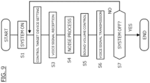
FIG. 9 is a flowchart of a control flow executed by a controller of the in-vehicle acoustic system according to a configuration. - The following describes one embodiment of an in-vehicle acoustic system according to the present invention based on the drawings.
FIG. 1 is a block diagram of a vehicle including the in-vehicle acoustic system according to one embodiment of the present invention. The in-vehicle acoustic system includes apower switch 1, amicrophone 2, aspeaker 3, an in-vehicle switch 4, acamera 5, acommunication device 6, and acontroller 10. The in-vehicle acoustic system is a system for controlling a conversation between passengers, a telephone call between a passenger and a user outside the vehicle, an output of a system sound of the in-vehicle system, and/or a sound environment at a specific seat through the speakers and/or microphones installed in a vehicle cabin. A device that includes at least themicrophone 2, thespeaker 3, and thecontroller 10 corresponds to an "in-vehicle acoustic device" of the present invention, and a control executed by thecontroller 10 corresponds to an "in-vehicle acoustic control method." - The
power switch 1 is a main switch of avehicle 200, and is a system for starting a driving source of thevehicle 200 and turning on an electrical system. The in-vehicle acoustic system is activated by turning on thepower switch 1. When thevehicle 200 includes an engine, thepower switch 1 corresponds to an ignition switch. - A plurality of the
microphones 2 are disposed in thevehicle 200, and they convert a sound, such as a voice of a passenger, into an electric signal and output it to thecontroller 10. Themicrophone 2 has a noise cancelling function. A plurality of thespeakers 3 are disposed in thevehicle 200, and they output any music and the like including the voice of the passenger, a voice of a user outside the vehicle, and a system sound of the in-vehicle system to each of the passengers in thevehicle 200. - As illustrated in
FIG. 2 , themicrophones 2 and thespeakers 3 are installed in the vehicle so as to correspond to seating positions (positions of seats) of the passengers in thevehicle 200.FIG. 2 is a drawing for describing positions of themicrophones 2 and thespeakers 3, and illustrates a plan view of thevehicle 200. - In the example in
FIG. 2 , thevehicle 200 is provided with six seats, three rows of two seats each. Themicrophones 2 are constituted of sixmicrophones 21 to 26, thespeakers 3 are constituted of sixteenspeakers microphone 21 and thespeakers microphone 22 and thespeakers microphone 23 and thespeakers 33a to 33d are installed so as to correspond to a position of a right side seat in a second row of the seats, and themicrophone 24 and thespeakers 34a to 34d are installed so as to correspond to a position of a left side seat in the second row of the seats. Themicrophone 25 and thespeakers microphone 26 and thespeakers microphones 2 are assigned to the seats such that a voice is easily received when a sitting passenger speaks. Thespeakers 3 are assigned to the seats such that a sound is easily heard by passengers when the sitting passengers hear the sound. - The
speakers speakers speakers speakers microphones 21 to 26 and thespeakers speakers controller 10. In the following description, themicrophones 2 and thespeakers 3 corresponding to the seating positions of the passengers are also simply referred to as "microphones of passengers" and "speakers of passengers," and when it is described as a microphone of a speaking person as a specific example of a passenger, it indicates a microphone corresponding to the seating position of the speaking person. For example, themicrophone 2 and thespeakers 3 of a driver correspond to themicrophone 21 and thespeakers - With reference to
FIG. 1 , the in-vehicle switch 4 is a switch for transmitting an operation command for controlling the in-vehicle acoustic system. The passenger operates the in-vehicle switch 4, and thus, is allowed to select a seat subject to a conversation, a seat with a blocked ambient sound, and a seat from which input of a sound is blocked. For example, when the in-vehicle switch 4 is installed near the driver's seat, and the driver operates the in-vehicle switch 4 to select a seat from which input of a sound is blocked, a voice input from themicrophone 2 of the selected seat is adjusted, and the voice of the passenger on the selected seat can be controlled not to reach the driver through the speakers. The in-vehicle switch 4 may be a touch panel in a navigation system, a switch around a dashboard, or a switch reachable by a hand of a passenger other than the driver. - The
camera 5 is an imaging device that obtains images of the passengers in the vehicle. Thecommunication device 6 is a device that enables a telephone call with a user outside the vehicle through a telephone line. Thecommunication device 6 may be connected to a mobile terminal, such as a smart phone owned by a passenger, and make a telephone call with a user outside the vehicle via the mobile terminal. At this time, the telephone call is made through themicrophone 2 and thespeaker 3 mounted in the vehicle, not through a microphone and a speaker of the mobile terminal. - The
controller 10 is a main controller of thevehicle 200, and controls various kinds of systems, such as a drive system of thevehicle 200 and a navigation system. As a processor for controlling the in-vehicle acoustic system, thecontroller 10 controls themicrophone 2 of the speaking person and thespeakers 3 of a hearing person so as to allow a voice of the speaking person input from themicrophone 2 to be heard by the hearing person other than the speaking person via thespeakers 3. Thecontroller 10 controls a sound volume of a reproduced voice output from thespeakers 3 of the hearing person based on a positional relation between the seating position of the speaking person and the seating position of the hearing person. In the example inFIG. 1 , the control unit of thevehicle 200 may be constituted of a plurality of control units, not limited to onecontroller 10. When the in-vehicle acoustic system is incorporated in an existing system of thevehicle 200, thecontroller 10 functions as a control unit for the in-vehicle acoustic system. - The
controller 10 has a sounddevice setting unit 11, avoice control unit 12, anoise processing unit 13, a telephone-call control unit 14, and an in-vehicle devicesound control unit 15 as function blocks, and programs for achieving respective functions in the respective function blocks are stored in a memory. The respective functions of the function blocks are achieved by a computer included in thecontroller 10 executing the programs. The function blocks are not limited to five, and there may be one to four or five or more function blocks. - The sound
device setting unit 11 sets sound devices as control targets for controlling sound environments at respective seats. The sound device corresponds to themicrophone 2 and thespeaker 3. The sounddevice setting unit 11 sets the sound device as the control target (a control target device) based on an operation command of the in-vehicle switch 4, a captured image of thecamera 5, and an external command received by thecommunication device 6. For example, when a passenger in the third row operates the in-vehicle switch 4 and selects a specific seat in order to have a conversation with a passenger in the first row, the sounddevice setting unit 11 sets themicrophone 2 and thespeakers 3 corresponding to the position of the seat of the conversation target as control target devices. When the sound environments are controlled corresponding to the seating position of the speaking person and the seating position of the hearing person in the vehicle cabin, the sounddevice setting unit 11 sets themicrophones 2 and thespeakers 3 of the speaking person and the hearing person as the control target devices. For example, in the example inFIG. 2 , when all the passengers sit on the seats, all themicrophones 2 and thespeakers 3 are the control target devices. - The sound
device setting unit 11 may set the control target device based on a captured image of thecamera 5. For example, the sounddevice setting unit 11 detects a passenger who is having a conversation from a face image included in a camera image, and sets themicrophone 2 and thespeakers 3 of the detected passenger as the control target devices. When detecting that a passenger is sleeping from a camera image, the sounddevice setting unit 11 sets a control target speaker so as to turn off thespeakers 3 of the passenger asleep. When detecting that a passenger is a child and is making a noise from a camera image, the sounddevice setting unit 11 sets a control target speaker so as to turn off themicrophone 2 of the child. - The sound
device setting unit 11 sets the control target device based on an external command received by thecommunication device 6. For example, when thecommunication device 6 receives a call command by telephone from outside of thevehicle 200 to the driver, the sounddevice setting unit 11 sets themicrophone 21 and thespeakers microphone 21 and thespeakers - The
voice control unit 12 controls a voice input/output from the control target devices set by the sounddevice setting unit 11. The control of the voice corresponds to adjustment of a sound volume and/or a position. The adjustment of the sound positioning may be adjusted by a magnitude of a sound volume of thespeakers 3 installed for a seat (for example, thespeakers speaker 3. For example, when a passenger in the third row makes a conversation with a passenger in the first row through themicrophones 2 and thespeakers 3, thevoice control unit 12 increases the sound volume from thespeakers 3 in the third row when the voice from the first row as the speaking person is output from thespeakers 3 in the third row. - The
noise processing unit 13 generates a noise reduction sound for reducing a noise input from themicrophone 2. The noise input to themicrophone 2 is, for example, a road noise, a booming noise of an engine, and a sound generated by a motor and an inverter. In the noise process, for example, the noise is detected through themicrophone 2 using a noise detection function (noise cancelling function) that themicrophone 2 has, and the noise process is executed on the detected noise. The noise process enhances, for example, an original voice drown out by the noise and outputs it from thespeakers 3. The noise process may, for example, cancel a sound other than the original voice by superimposing a signal of an opposite phase over a detected noise waveform. Thus, the noise processing unit reduces a noise on a real-time basis in accordance with a change in the noise inside and outside thevehicle 200. - The telephone-
call control unit 14 controls a telephone call between a user outside the vehicle and a passenger using thecommunication device 6. When thecommunication device 6 receives a telephone call from a user outside the vehicle, the telephone-call control unit 14 identifies the passenger as a destination of the telephone call. The telephone-call control unit 14 identifies the passenger by, for example, face authentication using a captured image of thecamera 5 and/or authentication using a key ID. The telephone-call control unit 14 transmits the information on the identified passenger to the sounddevice setting unit 11. The sounddevice setting unit 11 sets themicrophone 2 and thespeakers 3 of the passenger identified by the telephone-call control unit 14 as the control target devices. Additionally, the telephone-call control unit 14 controls the telephone call between the user outside the vehicle and the passenger during the telephone call between the user outside the vehicle and the passenger. - The in-vehicle device
sound control unit 15 outputs a notification sound by the in-vehicle device from thespeakers vehicle 200. The notification sound of the in-vehicle device is, for example, a guide voice of a navigation system. The information indicated by the notification sound of the in-vehicle device is necessary for the driver, but is not necessarily necessary for the passengers other than the driver. Therefore, when the notification sound of the in-vehicle device is output, the in-vehicle devicesound control unit 15 outputs the notification sound from thespeakers other speakers sound control unit 15 may change an output destination of the notification sound in accordance with the type of information indicated by the notification sound of the in-vehicle device. For example, when the information indicated by the notification sound of the in-vehicle device is shop information or the like, which is preferred to be provided to a passenger other than the driver, the in-vehicle devicesound control unit 15 may output the notification sound from theother speakers - Next, controls of sound environments by the
controller 10 will be described with specific examples. A control of a sound environment when a passenger in the first row and a passenger in the third row have a conversation will be described.FIG. 3 is a plan view of thevehicle 200, and illustrates a state where the passenger in the third row hears respective voices spoken by the passenger in the first row and a passenger in the second row. For icons indicative of the voices of the passengers inFIG. 3 , the solid lines indicate the voice of the passenger in the first row and the dotted lines indicate the voice of the passenger in the second row. - The sound
device setting unit 11 of thecontroller 10 sets themicrophones speakers voice control unit 12 of thecontroller 10 receives voice information of the passengers in the first and second rows through themicrophones voice control unit 12 outputs a reproduced voice of the passenger in the first row from thespeaker 36b, and outputs a reproduced voice of the passenger in the second row from thespeaker 36a. At this time, thevoice control unit 12 increases a sound volume of thespeaker 36b outputting the reproduced voice of the passenger in the second row to be larger than a sound volume of thespeaker 36a outputting the reproduced voice of the passenger in the first row. That is, when the passenger in the third row hears the voices of the passengers in the first and second rows, the sound volume of the passenger in the second row is larger than the sound volume of the passenger in the first row. Thus, thecontroller 10 reduces the sound volume of the reproduced voice as a distance between the seating position of the seat of the speaking person and the seating position of the seat of the hearing person increases. Thus, the magnitudes of the reproduced sound volumes heard by the passenger in the third row enables to create a sense of distance between the respective seats in the embodiment. - Next, a control of a sound environment when a passenger on the left side in the third row and a passenger on the right side in the first row have a conversation will be described.
-
FIG. 4 is a plan view of thevehicle 200, and illustrates a state where the right side passenger in the first row hears the voice spoken by the left side passenger in the third row. - The sound
device setting unit 11 of thecontroller 10 sets themicrophones speakers voice control unit 12 of thecontroller 10 receives voice information of the left side passenger in the third row through themicrophone 26. Thevoice control unit 12 outputs a reproduced voice of the left side passenger in the third row from thespeaker 31b, and does not output it from thespeaker 31a. That is, thevoice control unit 12 increases a reproduced sound volume of thespeaker 31b that is closer to the seating position of the left side passenger in the third row among thespeakers speaker 31a that is farther, and thus, the right side passenger in the first row can hear the voice from theleft side speaker 31b when the left side passenger in the third row speaks. Thus, thecontroller 10 increases the sound volume of the reproduced voice output from the speaker closer to the seating position of the speaking person among the plurality ofspeakers 3. In view of this, the magnitudes of the reproduced sound volumes output from the right and left speakers disposed at the respective seats enables to create a sense of direction in the embodiment. - Next, with reference to
FIGS. 5A, 5B , a control of a sound environment when all passengers have a conversation will be described.FIG. 5A is a table for describing on and off of the microphones/speakers in the first to third rows, andFIG. 5B is a table showing a correlation between the seating positions of the passengers and a voice audible by the passengers. - The sound
device setting unit 11 of thecontroller 10 sets themicrophones 2 and thespeakers 3 of the passengers in the first to third rows as the control target devices. The sounddevice setting unit 11 may detect whether the passengers are sitting on the seats or not using thecamera 5, seat sensors installed in the seats, or the like and set only themicrophones 2 and thespeakers 3 corresponding to the positions of the seats on which the passengers sit as the control target devices. When the passengers sit on the respective seats in the first to third rows, the sounddevice setting unit 11 turns on themicrophones 2 and thespeakers 3 of the passengers in the first row to the third row. When receiving voice information from the turned-on microphones, thevoice control unit 12 of thecontroller 10 controls a sound volume of a reproduced voice in accordance with the positional relation between the position of the microphone that has received the voice information and the positions of thespeakers 3 that output the reproduced voice. For example, as illustrated inFIG. 5B , when the passenger in the first row hears each of the voice of the passenger in the second row and the voice of the passenger in the third row, thevoice control unit 12 increases a sound volume of thespeakers speakers voice control unit 12 increases the sound volume of thespeakers speakers voice control unit 12 makes the sound volume of thespeakers 33a-33d and 34a-34d that output the reproduced voice of the passenger in the first row be the same volume as the sound volume of thespeakers 33a-33d and 34a-34d that output the reproduced voice of the passenger in the third row (make the reproduced sound volumes of the passengers in the first and third rows be a normal level). - That is, the
controller 10 reduces the sound volume of the reproduced sound volume as a distance between the seating position of the seat of the speaking person and the seating position of the seat of the hearing person increases. In view of this, the magnitudes of the reproduced sound volumes enable to create a sense of distance between the respective seats. For example, while the passengers in the first row and the second row are having a conversation, the passenger in the third row sometimes fails to participate in the conversation and feels isolated. In the embodiment, the passenger in the third row can smoothly participate in the conversation since he/she can easily hear the voices of the passengers in the first and second rows through themicrophones 2 and thespeakers 3. - Next, with reference to
FIGS. 6A, 6B , a control of a sound environment when a sound volume of a voice of a specific passenger is reduced so as to be unhearable by the other passengers. Such a sound environment may be applied to the following situations. For example, the situations include when a child in thevehicle 200 is making a noise and the voice of the child is desirably canceled. Other situations include when a driver would like to concentrate on driving or when a passenger on the front passenger seat would like to concentratedly hear a music while a lively conversation is taking place in the second row and the third row and the passengers are talking loudly.FIG. 6A is a table for describing on and off of the microphones/speakers in the first to third rows, andFIG. 6B is a table showing a correlation between the seating positions of the passengers and the voice audible by the passengers. - The sound
device setting unit 11 of thecontroller 10 identifies the seating positions for reducing the sound volume of the specific passenger based on an operation command of the in-vehicle switch 4 and/or a captured image of thecamera 5. For example, in the state where a child in the second row is making a noise, a driver would like to operate the in-vehicle switch 4 to cancel the voice of the child in the second row. In such a case, the driver operates the in-vehicle switch 4 so as to cancel the voice of the child, and the sounddevice setting unit 11 sets at least themicrophones speakers vehicle switch 4. Thevoice control unit 12 receives voice information of the passenger in the second row through themicrophone 23 or themicrophone 24, and reduces a sound volume of the voice of the passenger in the second row when it is output from thespeakers - The
controller 10 controls themicrophones 2 and thespeakers 3 corresponding to the respective seating positions similarly to the above-described sound environment control when the passengers make a conversation between the first row and the third row. As illustrated inFIG. 6A , thespeakers 3 in the first row and the third row output the voices of the respective seats, but cancel the voice of the seat in the second row. As illustrated inFIG. 6B , the passengers in the first row and the third row are able to hear the voices of one another, but not able to hear the voice of the passenger in the second row. The passenger in the second row is able to hear the voices of the passengers in the first row and the third row from thespeakers 33a to 33d, and 34a to 34d. Therefore, the situation in which the passenger in the second row fails to participate in the conversation between the passenger in the first row and the passenger in the third row and feels isolated is avoidable. - Thus, the in-
vehicle switch 4 has a function of adjusting a sound volume of a specific voice input from themicrophone 2 corresponding to a certain seating position among the plurality of seats in the vehicle cabin. The passenger operates the in-vehicle switch 4 and selects the seat of which the sound volume is reduced. Thecontroller 10 reduces the sound volume of the specific voice when it is output from the speakers based on the operation command of the in-vehicle switch 4. Alternatively, thecontroller 10 may inactivate the microphone installed in the specific seat (for example, the microphones in the second row). This enables to provide a sound environment in which a specific passenger's voice is not audible by the other passengers. Furthermore, the sound environment appropriate for conversation is provided between the seats other than the specific seating position, and therefore, the conversation can smoothly take place. - Not limited to the operation command of the in-
vehicle switch 4, thecontroller 10 may reduce the sound volume of the specific passenger based on a captured image of thecamera 5. For example, thecontroller 10 detects that a child is making a noise from the captured image of the camera. At this time, thecontroller 10 may detect that the child is making a noise from the voice detected by themicrophone 2 of the child. Thecontroller 10 then reduces the sound volume of the child voice when the child voice input from themicrophone 2 of the child is output from thespeakers 3. In view of this, the sound environment in which the voice of the child is not audible by the other passengers is providable. - While in the example in
FIGS. 6A, 6B , thecontroller 10 controls to reduce the sound volume of the voice input from the passenger of the specific seat to be small, thecontroller 10 may control to increase a sound volume of a voice output from the speakers corresponding to a specific seating position, as a modification example of the embodiment. For example, when a sound volume of a voice of oneself is desirably increased to transmit the voice to a passenger on a seat far away in a conversation in a vehicle, thecontroller 10 may execute the control like the modification. Specifically, the in-vehicle switch 4 has a function to increase the sound volume of the voice output from thespeakers 3 corresponding to the specific seating position among the plurality of seats in the vehicle cabin. The passenger operates the in-vehicle switch 4 so as to increase the voice of his/her own output from the speakers. At this time, the operation of the in-vehicle switch 4 may allow the speakers from which his/her own voice with increased sound volume is output to be selected by seat. Thecontroller 10 then increases the sound volume of the reproduced voice when it is output from thespeakers 3 based on the operation command of the in-vehicle switch 4 in the case where the voice of the speaking person is reproduced. In view of this, operation of a switch allows the specific passenger to easily hear another passenger's voice. - While in the above-described modification, the
controller 10 increases the sound volume of the reproduced voice when it is output from thespeakers 3 based on the operation command of the in-vehicle switch 4 in the case where the voice of the speaking person is reproduced, a target passenger whose voice is increased may be detected based, for example, on a captured image of thecamera 5, not limited to the operation command of the in-vehicle switch 4, and the sound volume may be increased when the reproduced sound volume of the detected passenger is output in thespeakers 3 of the other seats. Specifically, the sounddevice setting unit 11 executes image processing on the captured image of thecamera 5, detects, for example, a passenger who wears a face mask, and sets at least themicrophone 2 of the passenger wearing the face mask and the speakers of the other passengers having a conversation with this passenger as the control target speakers. Thevoice control unit 12 then increases a sound volume of the reproduced voice when it is output from thespeakers 3 of the other passengers in the case where the voice of the passenger wearing the face mask is reproduced. Thus, thecontroller 10 increases the sound volume of the specific voice when the specific voice input from themicrophone 2 corresponding to the specific seating position among the plurality of seats is output from thespeakers 3. This allows a voice to be easily heard, even in a situation where, for example, a passenger wears a face mask and his/her voice is difficult to hear. Thevoice control unit 12 may increase sensitivity of themicrophone 2 of the passenger who wears the face mask. - Next, with reference to
FIGS. 7A, 7B , a control of a sound environment when the other passengers' voices are made unhearable for a specific passenger will be described. Such a sound environment is applied to the case where, for example, a passenger is asleep and the ambient sound is desirably reduced.FIG. 7A is a table for describing on and off of the microphones/speakers in the first to third rows, andFIG. 7B is a table showing a correlation between the seating positions of the passengers and the voice audible by the passengers. - The sound
device setting unit 11 of thecontroller 10 identifies the seating positions for reducing a sound volume of a specific passenger based on an operation command of the in-vehicle switch 4 and/or a captured image of thecamera 5. For example, assume that a voice output from the speakers in the second row is desirably cancelled by another passenger operating the in-vehicle switch 4 while a passenger in the second row is asleep. In such a case, the other passenger operates the in-vehicle switch 4 to cancel the voice output in the second row, the sounddevice setting unit 11 sets at least, thespeakers 33a to 33d and 34a to 34d of the passenger in the second row as the control target speakers based on the operation command of the in-vehicle switch 4. Thevoice control unit 12 then reduces a sound volume of the voice output from thespeakers 33a to 33d and 34a to 34d in the second row. A control of reducing the sound volume includes a control of lowering a sound volume level or a control of making the sound volume zero. Thecontroller 10 controls themicrophones 2 and thespeakers 3 corresponding to the respective seating positions similarly to the above-described sound environment control when the passengers make a conversation between the first row and the third row. As illustrated inFIG. 7A , thespeakers 3 have the reduced sound volume or thespeakers 3 are turned off in the second row seats, and thespeakers 3 in the first row and the third row output the voices of the passengers of the other seats. Themicrophones 2 are turned on in the first to third rows. As illustrated inFIG. 7B , the passenger in the second row is unable to hear the voice from thespeakers 3, and the passengers in the first and third rows are able to hear the voices of the passengers in the other rows from thespeakers 3. - Thus, the in-
vehicle switch 4 has a function to adjust a sound volume of a specific voice input from themicrophone 2 corresponding to a specific seating position among the plurality of seats in the vehicle cabin. The passenger then operates the in-vehicle switch 4 and selects the seat to have a reduced sound volume. In the example inFIGS. 7A and 7B , themicrophones 2 as the sound volume adjustment targets are the microphones in the first and third rows, and thespeakers 3 with the reduced sound volume are the speakers in the second row. In the example inFIGS. 7A and 7B , thecontroller 10 reduces the sound volume when it is input from themicrophones speakers 33a to 33d and 34a to 34d of the passenger in the second row. This enables to provide a sound environment in which a specific passenger is unable to hear the other passengers' voices. - The
controller 10 may determine whether a passenger in the vehicle cabin is asleep based on a captured image of thecamera 5. Whether the passenger is asleep or not is determined simply by using a known monitoring system. Thecontroller 10 reduces a sound volume of reproduced voices of the other passengers output from thespeakers 3 of the passenger asleep when determining that the passenger is asleep. This enables to provide a comfortable environment for sleep of the passenger. - As a modification example of the embodiment, the
noise processing unit 13 of thecontroller 10 may increase a noise reduction sound output from thespeakers 3 of the passenger in a sleep when determining that the passenger is asleep. Increased noise reduction sound enables to provide a comfortable environment for sleep of the passenger because the noise around the passenger asleep is blocked. - Next, with reference to
FIGS. 8A, 8B , a control of a sound environment where a telephone call from a user outside the vehicle is received will be described.FIG. 8A is a table for describing on and off of the microphones/speakers in the first to third rows, andFIG. 8B is a table showing a correlation between the seating positions of the passengers and the voice audible by the passengers. - For example, when the
communication device 6 receives a call command by telephone from outside thevehicle 200 to a driver, the sounddevice setting unit 11 sets themicrophone 21 and thespeakers microphone 21 and thespeakers device setting unit 11 sets themicrophones 23 to 26 and thespeakers 33a to 33d, 34a to 34d, 35a, 35b, 36a, and 36b as the control target devices so as to allow a conversation between the passengers in the second row and the third row. When the telephone call destination from outside is a passenger other than the driver, the sounddevice setting unit 11 simply sets the control target devices such that the passenger of the call destination is able to talk to the external user through themicrophone 2 and thespeakers 3 and the other passengers are able to have a conversation. - The
voice control unit 12 control a sound volume of thespeakers 3 so as to output a voice of a telephone only from thespeakers 3 of the passenger as the call destination when the voice of the telephone from the user outside the vehicle is output. When the telephone call is for the driver, as illustrated inFIG. 8A , thevoice control unit 12 outputs the telephone voice but not the voices of the passengers in the second and third rows from the speakers in the first row. Thevoice control unit 12 also outputs the voices of the passengers in the second and third rows but not the telephone voice from the speakers in the second row and the third row. Themicrophones 2 are on in the first to third rows. As illustrated inFIG. 8B , the passenger in the first row is able to hear only the telephone voice from thespeakers 3, and the passengers in the second and third rows are able to hear the voices of the other passengers in the second and third rows from thespeakers 3. This enables to provide the voice of the telephone call from outside the vehicle only to the passenger in need. In addition, a sound environment appropriate for conversation can be provided at the seats of the passengers not involved in the telephone call. - While the controls of the sound environments by the
controller 10 have been described with the specific examples above, the following controls may be combined. When a notification sound of in-vehicle device is emitted while a driver is having a conversation with another passenger using the in-vehicle acoustic system according to the embodiment, thecontroller 10 may output the notification sound of the in-vehicle device from thespeakers controller 10 may increase a sound volume of the notification sound of the in-vehicle device to be larger than a sound volume of the voice of the other passenger. When the notification sound of the in-vehicle device relates only to the driver, thecontroller 10 may output the notification sound of the in-vehicle device only from thespeakers controller 10 may reduce the sound volume of the voice of the passenger when the notification sound of the in-vehicle device is output from thespeakers - In the embodiment, when a system sound generated by a navigation system is output, the
controller 10 may output the system sound only from thespeakers speakers - In the embodiment, the
noise processing unit 13 of thecontroller 10 may execute a noise process when a voice of a passenger is output from thespeakers 3. At this time, thevoice control unit 12 increases the sound volume of the reproduced voice that reproduces the voice of the passenger as the sound volume of the noise reduction sound generated by thenoise processing unit 13 is larger. For example, when the frequency band of the noise reduction sound and the frequency band of the voice of the passenger overlap, the sound volume of the voice of the passenger could be reduced because of the noise reduction sound. In such a case, increasing the sound volume of the reproduced voice in accordance with the magnitude of the noise reduction sound, a sound environment appropriate for a conversation by the passengers can be provided. - Next, with reference to
FIG. 9 , a control flow executed by thecontroller 10 will be described.FIG. 9 is a flow chart for describing a procedure of an in-vehicle acoustic control method executed by thecontroller 10. - At Step S1, when the
power switch 1 is turned on, thecontroller 10 activates the in-vehicle acoustic system (system ON). At Step S2, thecontroller 10 sets the control target device based on an operation command of the in-vehicle switch 4, a captured image of thecamera 5, and an external command received by thecommunication device 6. That is, thecontroller 10 determines themicrophones 2 and thespeakers 3 to be controlled under the in-vehicle acoustic system in order to provide an appropriate sound environment corresponding to the situations of the passengers and/or the vehicle based on the operation command of the in-vehicle switch 4 and the like. For example, when the passengers are having a conversation in the vehicle cabin, thecontroller 10 sets at least themicrophones 2 and thespeakers 3 of the passengers in the conversation as the control target devices. - At Step S3, the
controller 10 receives a signal including a voice of a speaking person from themicrophone 2 of the speaking person among the passengers who are having a conversation. At Step S4, thecontroller 10 executes the noise process when the signal including the voice of the speaking person includes a noise. At Step S5, thecontroller 10 controls a sound volume of a reproduced voice output from thespeakers 3 of other passengers based on a positional relation between a seating position of the speaking person and seating positions of the other passengers who hear the voice when the voice of the speaking person is heard by the other passengers. For example, thecontroller 10 controls the sound volume of the reproduced voice in accordance with distances between the seating position of the speaking person and the seating positions of the other passengers who hear the voice and/or directions of the seating positions of the other passengers with respect to the seating position of the speaking person. - At Step S6, the
controller 10 outputs the signal including the controlled reproduced sound volume to thespeakers 3 of the other passengers. At Step S7, thecontroller 10 determines whether the in-vehicle acoustic system is turned off or not. For example, when an operation command to turn off the system or a command to turn off thepower switch 1 is input to thecontroller 10 by the operation of the in-vehicle switch 4, thecontroller 10 turns the in-vehicle acoustic system off, and thus, the control flow illustrated inFIG. 9 is terminated. On the other hand, when determining that the in-vehicle acoustic system is not turned off, the control flow is returned to Step S2, and thecontroller 10 executes the control flow at Step S2 and thereafter. This optimizes the sound environments of the respective seats under the in-vehicle acoustic system during the conversation between the passengers. - As described above, the in-vehicle acoustic device according to the embodiment includes the
controller 10 that controls themicrophones 2 corresponding to the seating position of the speaking person (corresponding to a "first passenger" of the present invention) and thespeakers 3 corresponding to the seating position of the hearing person (corresponding to a "second passenger" of the present invention) so as to cause the voice of the speaking person (corresponding to the "first passenger" of the present invention) input from themicrophone 2 to be heard by the hearing person (corresponding to the "second passenger" of the present invention) via thespeakers 3. Thecontroller 10 controls a sound volume of a reproduced voice output from thespeakers 3 corresponding to the seating position of the hearing person based on the positional relation between the seating position of the speaking person and the seating position of the hearing person. This enables the passengers to have a smooth conversation through the microphones and the speakers in the vehicle cabin. - While in the specific example describing with reference to FIG. 3A, FIG. 3B,
FIG. 5A, FIG. 5B ,FIG. 6A, FIG. 6B ,FIG. 7A, FIG. 7B ,FIG. 8A, and FIG. 8B , the control of themicrophones 2 and thespeakers 3 has been described as the control for each row of the first to third rows for facilitating the description, the control may be executed for each seat in the specific example as well. - The embodiment described above has been described for ease of understanding of the present invention, and has not been described for limiting the present invention. Accordingly, each component disclosed in the above-described embodiment has a gist including even all the design changes and equivalents belonging to the technical scope of the present invention.
-
- 1
- power switch
- 2
- microphone
- 3
- speaker
- 4
- in-vehicle switch
- 5
- camera
- 6
- communication device
- 10
- controller
- 11
- sound device setting unit
- 12
- voice control unit
- 13
- noise processing unit
- 14
- telephone-call control unit
- 15
- in-vehicle device sound control unit
- 200
- vehicle
Claims (14)
- An in-vehicle acoustic device disposed in a vehicle, comprising:a plurality of speakers disposed in the vehicle;a plurality of microphones disposed in the vehicle; anda controller that controls the microphone corresponding to a first seating position of a first passenger and the speaker corresponding to a second seating position of a second passenger so as to cause a voice of the first passenger input from the microphone to be heard by the second passenger other than the first passenger via the speaker, whereinthe controller controls a sound volume of a reproduced voice output from the speaker corresponding to the second seating position based on a positional relation between the first seating position and the second seating position.
- The in-vehicle acoustic device according to claim 1, wherein
the controller reduces the sound volume of the reproduced voice as a distance between the first seating position and the second seating position increases. - The in-vehicle acoustic device according to claim 1 or 2, whereinthe plurality of speakers are disposed corresponding to the second seating position, andthe controller increases the sound volume of the reproduced voice output from the speaker closer to the first seating position among the plurality of speakers.
- The in-vehicle acoustic device according to any one of claims 1 to 3, wherein
the controller outputs a notification sound by an in-vehicle device from the speaker corresponding to a driver's seat of the vehicle. - The in-vehicle acoustic device according to any one of claims 1 to 4, comprisinga noise processing unit that generates a noise reduction sound for reducing a noise input from the microphone, whereinthe controller increases the sound volume of the reproduced voice output from the speaker as a sound volume of the noise reduction sound is larger.
- The in-vehicle acoustic device according to any one of claims 1 to 5, comprisingan in-vehicle switch for adjusting a sound volume of a specific voice input from the microphone corresponding to a specific seating position among a plurality of seats in a vehicle cabin, whereinthe controller reduces the sound volume of the specific voice when the specific voice is output from the speaker based on an operation command of the in-vehicle switch.
- The in-vehicle acoustic device according to any one of claims 1 to 5, wherein
when a voice input from the microphone corresponding to a specific seating position among the plurality of seats in a vehicle cabin is output from the speaker, the controller increases a sound volume of the voice. - The in-vehicle acoustic device according to any one of claims 1 to 7, wherein
when a voice input from the microphone corresponding to a seating position of a child among the plurality of seats in a vehicle cabin is output from the speaker, the controller reduces a sound volume of the voice. - The in-vehicle acoustic device according to any one of claims 1 to 8, wherein
the controller:determines whether a passenger in a vehicle cabin is asleep or not, andwhen determining that the passenger is asleep, reduces a sound volume of the reproduced voice output from the speaker corresponding to the seating position of the passenger in a sleep. - The in-vehicle acoustic device according to any one of claims 1 to 4, comprisinga noise processing unit that generates a noise reduction sound that reduces a noise inside the vehicle input from the microphone, whereinthe controller:determines whether a passenger in a vehicle cabin is asleep or not; andwhen determining that the passenger is asleep, increases the noise reduction sound output from the speaker corresponding to the seating position of the passenger in a sleep.
- The in-vehicle acoustic device according to any one of claims 1 to 10, comprising
an in-vehicle switch for increasing the sound volume of the reproduced voice output from the speaker corresponding to the specific seating position among the plurality of seats in the vehicle cabin. - The in-vehicle acoustic device according to any one of claims 1 to 11, wherein
when a system sound generated by a navigation system is output, the controller outputs the system sound only from the speaker corresponding to the driver's seat. - The in-vehicle acoustic device according to any one of claims 1 to 11, wherein
when a voice of a telephone call from a user outside the vehicle is output, the controller outputs the telephone voice only from the speaker corresponding to a seating position of a passenger as a telephone call destination. - An in-vehicle acoustic control method of controlling an in-vehicle acoustic sound executed by a processor, comprising:receiving a signal including a voice of a first passenger from a microphone corresponding to a first seating position of the first passenger among a plurality of the microphones disposed in a vehicle;when the voice of the first passenger input from the microphone is caused to be heard by a second passenger other than the first passenger via a speaker, controlling a sound volume of a reproduced voice output from the speaker corresponding to a second seating position based on a positional relation between the first seating position and the second seating position of the second passenger; andtransmitting a signal including the controlled reproduced voice to the speaker corresponding to the second seating position.
Applications Claiming Priority (1)
| Application Number | Priority Date | Filing Date | Title |
|---|---|---|---|
| PCT/JP2022/022327 WO2023233586A1 (en) | 2022-06-01 | 2022-06-01 | In-vehicle acoustic device and in-vehicle acoustic control method |
Publications (2)
| Publication Number | Publication Date |
|---|---|
| EP4535823A1 true EP4535823A1 (en) | 2025-04-09 |
| EP4535823A4 EP4535823A4 (en) | 2025-08-13 |
Family
ID=89026074
Family Applications (1)
| Application Number | Title | Priority Date | Filing Date |
|---|---|---|---|
| EP22944058.1A Withdrawn EP4535823A4 (en) | 2022-06-01 | 2022-06-01 | ON-BOARD ACOUSTIC DEVICE AND ON-BOARD ACOUSTIC CONTROL METHOD |
Country Status (4)
| Country | Link |
|---|---|
| EP (1) | EP4535823A4 (en) |
| JP (1) | JPWO2023233586A1 (en) |
| CN (1) | CN119256558A (en) |
| WO (1) | WO2023233586A1 (en) |
Family Cites Families (9)
| Publication number | Priority date | Publication date | Assignee | Title |
|---|---|---|---|---|
| DE10217778A1 (en) * | 2002-04-18 | 2003-11-06 | Volkswagen Ag | Communication device for the transmission of acoustic signals in a motor vehicle |
| JP3410244B2 (en) * | 1995-04-17 | 2003-05-26 | 富士通テン株式会社 | Automotive sound system |
| JPH0983277A (en) * | 1995-09-18 | 1997-03-28 | Fujitsu Ten Ltd | Sound volume adjustment device |
| JPH11342799A (en) * | 1998-06-03 | 1999-12-14 | Mazda Motor Corp | Conversation support device for vehicles |
| CN109642693B (en) | 2016-08-02 | 2020-10-23 | 法斯泰斯特公司 | Female threaded retained fluid connector |
| JP2019068237A (en) * | 2017-09-29 | 2019-04-25 | 株式会社デンソーテン | Conversation support device, conversation support system, and conversation support method |
| JP7124506B2 (en) * | 2018-07-17 | 2022-08-24 | 日本電信電話株式会社 | Sound collector, method and program |
| JP7268582B2 (en) * | 2019-11-12 | 2023-05-08 | トヨタ自動車株式会社 | Vehicle silencer and vehicle silencer |
| JP2022065711A (en) * | 2020-10-16 | 2022-04-28 | アルプスアルパイン株式会社 | Voice system |
-
2022
- 2022-06-01 WO PCT/JP2022/022327 patent/WO2023233586A1/en not_active Ceased
- 2022-06-01 JP JP2024524076A patent/JPWO2023233586A1/ja active Pending
- 2022-06-01 EP EP22944058.1A patent/EP4535823A4/en not_active Withdrawn
- 2022-06-01 CN CN202280096424.5A patent/CN119256558A/en active Pending
Also Published As
| Publication number | Publication date |
|---|---|
| CN119256558A (en) | 2025-01-03 |
| EP4535823A4 (en) | 2025-08-13 |
| WO2023233586A1 (en) | 2023-12-07 |
| JPWO2023233586A1 (en) | 2023-12-07 |
Similar Documents
| Publication | Publication Date | Title |
|---|---|---|
| CA2581774C (en) | Vehicle communication system | |
| EP1882387B1 (en) | System and method for creating personalized sound zones | |
| US9743213B2 (en) | Enhanced auditory experience in shared acoustic space | |
| JP7049803B2 (en) | In-vehicle device and audio output method | |
| US20110216913A1 (en) | Communication improvement in vehicles | |
| US20160127827A1 (en) | Systems and methods for selecting audio filtering schemes | |
| KR20180044878A (en) | Techniques for generating multiple audible scenes through a highly directional loudspeaker | |
| US10645494B1 (en) | Active control system for a vehicular dual microphone and a control method thereof | |
| JP2022516058A (en) | Hybrid in-car speaker and headphone-based acoustic augmented reality system | |
| US20060023892A1 (en) | Communications device for transmitting acoustic signals in a motor vehicle | |
| US20050221877A1 (en) | Methods for controlling processing of outputs to a vehicle wireless communication interface | |
| WO2005101674A1 (en) | Methods for controlling processing of inputs to a vehicle wireless communication interface | |
| WO2023233586A1 (en) | In-vehicle acoustic device and in-vehicle acoustic control method | |
| JPWO2023233586A5 (en) | ||
| US11985495B2 (en) | Audio control in vehicle cabin | |
| CN117412216B (en) | Earphone, control method and control device thereof | |
| JP2003224653A (en) | Hands-free communication device and method for controlling speaker thereof | |
| KR20150047652A (en) | Car audio apparatus | |
| US12587815B2 (en) | Call support system, call support method, and recording medium | |
| CN120895015A (en) | An audio processing method, apparatus, electronic device, and storage medium for a vehicle. | |
| JP2021034781A (en) | Sound system | |
| CN112896061A (en) | Sound system | |
| EP4664924A1 (en) | Electronic audio communication system for creating isolated audio communication zones within a closed environment and audio communication method thereof | |
| US12598424B2 (en) | Zoned audio duck for in car conversation | |
| US20250301532A1 (en) | Vehicle communication apparatus |
Legal Events
| Date | Code | Title | Description |
|---|---|---|---|
| STAA | Information on the status of an ep patent application or granted ep patent |
Free format text: STATUS: THE INTERNATIONAL PUBLICATION HAS BEEN MADE |
|
| PUAI | Public reference made under article 153(3) epc to a published international application that has entered the european phase |
Free format text: ORIGINAL CODE: 0009012 |
|
| STAA | Information on the status of an ep patent application or granted ep patent |
Free format text: STATUS: REQUEST FOR EXAMINATION WAS MADE |
|
| 17P | Request for examination filed |
Effective date: 20241223 |
|
| AK | Designated contracting states |
Kind code of ref document: A1 Designated state(s): AL AT BE BG CH CY CZ DE DK EE ES FI FR GB GR HR HU IE IS IT LI LT LU LV MC MK MT NL NO PL PT RO RS SE SI SK SM TR |
|
| STAA | Information on the status of an ep patent application or granted ep patent |
Free format text: STATUS: THE APPLICATION HAS BEEN WITHDRAWN |
|
| A4 | Supplementary search report drawn up and despatched |
Effective date: 20250715 |
|
| RIC1 | Information provided on ipc code assigned before grant |
Ipc: H04R 3/00 20060101AFI20250709BHEP Ipc: G10K 11/178 20060101ALI20250709BHEP Ipc: H04R 1/02 20060101ALI20250709BHEP Ipc: H04R 3/12 20060101ALI20250709BHEP |
|
| 18W | Application withdrawn |
Effective date: 20250729 |