EP4535650A1 - Transport device - Google Patents
Transport device Download PDFInfo
- Publication number
- EP4535650A1 EP4535650A1 EP23809962.6A EP23809962A EP4535650A1 EP 4535650 A1 EP4535650 A1 EP 4535650A1 EP 23809962 A EP23809962 A EP 23809962A EP 4535650 A1 EP4535650 A1 EP 4535650A1
- Authority
- EP
- European Patent Office
- Prior art keywords
- magnetic pole
- current
- magnetic
- electromagnet
- winding
- Prior art date
- Legal status (The legal status is an assumption and is not a legal conclusion. Google has not performed a legal analysis and makes no representation as to the accuracy of the status listed.)
- Pending
Links
Images


Classifications
-
- H—ELECTRICITY
- H02—GENERATION; CONVERSION OR DISTRIBUTION OF ELECTRIC POWER
- H02P—CONTROL OR REGULATION OF ELECTRIC MOTORS, ELECTRIC GENERATORS OR DYNAMO-ELECTRIC CONVERTERS; CONTROLLING TRANSFORMERS, REACTORS OR CHOKE COILS
- H02P25/00—Arrangements or methods for the control of AC motors characterised by the kind of AC motor or by structural details
- H02P25/02—Arrangements or methods for the control of AC motors characterised by the kind of AC motor or by structural details characterised by the kind of motor
- H02P25/06—Linear motors
- H02P25/064—Linear motors of the synchronous type
-
- G—PHYSICS
- G01—MEASURING; TESTING
- G01N—INVESTIGATING OR ANALYSING MATERIALS BY DETERMINING THEIR CHEMICAL OR PHYSICAL PROPERTIES
- G01N35/00—Automatic analysis not limited to methods or materials provided for in any single one of groups G01N1/00 - G01N33/00; Handling materials therefor
- G01N35/02—Automatic analysis not limited to methods or materials provided for in any single one of groups G01N1/00 - G01N33/00; Handling materials therefor using a plurality of sample containers moved by a conveyor system past one or more treatment or analysis stations
- G01N35/04—Details of the conveyor system
-
- B—PERFORMING OPERATIONS; TRANSPORTING
- B60—VEHICLES IN GENERAL
- B60L—PROPULSION OF ELECTRICALLY-PROPELLED VEHICLES; SUPPLYING ELECTRIC POWER FOR AUXILIARY EQUIPMENT OF ELECTRICALLY-PROPELLED VEHICLES; ELECTRODYNAMIC BRAKE SYSTEMS FOR VEHICLES IN GENERAL; MAGNETIC SUSPENSION OR LEVITATION FOR VEHICLES; MONITORING OPERATING VARIABLES OF ELECTRICALLY-PROPELLED VEHICLES; ELECTRIC SAFETY DEVICES FOR ELECTRICALLY-PROPELLED VEHICLES
- B60L13/00—Electric propulsion for monorail vehicles, suspension vehicles or rack railways; Magnetic suspension or levitation for vehicles
- B60L13/03—Electric propulsion by linear motors
-
- B—PERFORMING OPERATIONS; TRANSPORTING
- B65—CONVEYING; PACKING; STORING; HANDLING THIN OR FILAMENTARY MATERIAL
- B65G—TRANSPORT OR STORAGE DEVICES, e.g. CONVEYORS FOR LOADING OR TIPPING, SHOP CONVEYOR SYSTEMS OR PNEUMATIC TUBE CONVEYORS
- B65G54/00—Non-mechanical conveyors not otherwise provided for
- B65G54/02—Non-mechanical conveyors not otherwise provided for electrostatic, electric, or magnetic
-
- G—PHYSICS
- G01—MEASURING; TESTING
- G01N—INVESTIGATING OR ANALYSING MATERIALS BY DETERMINING THEIR CHEMICAL OR PHYSICAL PROPERTIES
- G01N35/00—Automatic analysis not limited to methods or materials provided for in any single one of groups G01N1/00 - G01N33/00; Handling materials therefor
- G01N35/00584—Control arrangements for automatic analysers
-
- H—ELECTRICITY
- H02—GENERATION; CONVERSION OR DISTRIBUTION OF ELECTRIC POWER
- H02K—DYNAMO-ELECTRIC MACHINES
- H02K41/00—Propulsion systems in which a rigid body is moved along a path due to dynamo-electric interaction between the body and a magnetic field travelling along the path
- H02K41/02—Linear motors; Sectional motors
- H02K41/03—Synchronous motors; Motors moving step by step; Reluctance motors
- H02K41/031—Synchronous motors; Motors moving step by step; Reluctance motors of the permanent magnet type
-
- G—PHYSICS
- G01—MEASURING; TESTING
- G01N—INVESTIGATING OR ANALYSING MATERIALS BY DETERMINING THEIR CHEMICAL OR PHYSICAL PROPERTIES
- G01N35/00—Automatic analysis not limited to methods or materials provided for in any single one of groups G01N1/00 - G01N33/00; Handling materials therefor
- G01N35/02—Automatic analysis not limited to methods or materials provided for in any single one of groups G01N1/00 - G01N33/00; Handling materials therefor using a plurality of sample containers moved by a conveyor system past one or more treatment or analysis stations
- G01N35/04—Details of the conveyor system
- G01N2035/0474—Details of actuating means for conveyors or pipettes
- G01N2035/0477—Magnetic
-
- G—PHYSICS
- G01—MEASURING; TESTING
- G01N—INVESTIGATING OR ANALYSING MATERIALS BY DETERMINING THEIR CHEMICAL OR PHYSICAL PROPERTIES
- G01N35/00—Automatic analysis not limited to methods or materials provided for in any single one of groups G01N1/00 - G01N33/00; Handling materials therefor
- G01N35/02—Automatic analysis not limited to methods or materials provided for in any single one of groups G01N1/00 - G01N33/00; Handling materials therefor using a plurality of sample containers moved by a conveyor system past one or more treatment or analysis stations
- G01N35/04—Details of the conveyor system
- G01N2035/0474—Details of actuating means for conveyors or pipettes
- G01N2035/0491—Position sensing, encoding; closed-loop control
- G01N2035/0493—Locating samples; identifying different tube sizes
Definitions
- the present invention relates to a conveyance apparatus, for example, a conveyance apparatus suitable for a specimen analysis system that analyzes a biological sample such as blood or urine (hereinafter referred to as a specimen) and a specimen pretreatment apparatus that performs a pretreatment required for an analysis.
- a conveyance apparatus suitable for a specimen analysis system that analyzes a biological sample such as blood or urine (hereinafter referred to as a specimen) and a specimen pretreatment apparatus that performs a pretreatment required for an analysis.
- PTL 1 discloses that a current is caused to flow only through a winding of a magnetic circuit to induce an inductance change due to magnetic saturation and thus detect a position.
- PTL 2 discloses a method in which, for a container carrier deviated from a conveyance path and stopped, a voltage pulse is applied to a certain coil to generate an attractive force toward a magnet provided in the container carrier, and voltage pulses are applied indiscriminately to a plurality of coils around the coil that generates the attractive force to generate a repulsive force against the magnet, thereby detecting a position of the container carrier.
- examples of the container carrier 110 include a specimen holder that holds one single specimen container such as a test tube or a sample cell containing a liquid specimen, and a specimen rack that holds a plurality of specimen containers.
- the first winding 21a and the second winding 21b of the first electromagnet 25a and the second electromagnet 25b are respectively connected to the first drive circuit 50a and the second drive circuit 50b.
- the first current detection unit 40a and the second current detection unit 40b have a function of detecting currents flowing through the first winding 21a and the second winding 21b of the first electromagnet 25a and the second electromagnet 25b from the first drive circuit 50a and the second drive circuit 50b, respectively, and transmitting current values detected by the first current detection unit 40a and the second current detection unit 40b to the calculation unit 41.
- the calculation unit 41 outputs, to the first drive circuit 50a and the second drive circuit 50b, a control signal for moving the container carrier 110 using the current values detected by the first current detection unit 40a and the second current detection unit 40b. Accordingly, the container carrier 110 can be conveyed to a desired position.
- the first current detection unit 40a and the second current detection unit 40b may measure a voltage across a series resistor, may use a current transformer, or may use a Hall current sensor, and are not limited thereto.
- FIG. 2 shows an example of an arrangement configuration of the first electromagnet 25a, the second electromagnet 25b and a fifth electromagnet 25e that are adjacent magnetic poles disposed in a traveling direction of the container carrier 110 with respect to the first electromagnet 25a, and a third electromagnet 25c and a fourth electromagnet 25d that are adjacent magnetic poles disposed adjacent to the first electromagnet 25a in a normal direction of the container carrier 110 in the conveyance apparatus 1 in the embodiment (an arrangement configuration of electromagnets in a comparative example (related art) to be described later is also the same arrangement configuration).
- a yoke is not shown.
- a position directly above the first electromagnet 25a is a target stop position, and the container carrier 110 moves on a conveyance surface 65 from the side of the third electromagnet 25c toward the first electromagnet 25a.
- a current is caused to flow only through the first electromagnet 25a located at the stop target position.
- a magnetic field generated by the first electromagnet 25a acts to drive the container carrier 110 leftward in FIG. 3 .
- a magnetic flux 71 of the permanent magnet provided in the container carrier 110 links with the first electromagnet 25a, enhances a magnetic flux 70a generated by the first electromagnet 25a, thus the inside of the first electromagnet 25a is magnetically saturated and an inductance decreases.
- the position of the container carrier 110 is detected using such a change in the inductance (for example, the position of the container carrier 110 is specified by a value of the change in the inductance).
- FIG. 7 shows a relationship of the inductance with respect to a distance between the container carrier 110 and the first electromagnet 25a in the first embodiment of the conveyance apparatus 1 according to the invention, where a broken line indicates a case where no current flows to an adjacent coil, and a solid line indicates a case where a current flows through the adjacent coil.
- the inductance when no current flows to the adjacent coil, the inductance changes from 1 p.u. to about 0.89 p.u., and when the adjacent coil is energized, the inductance changes from 1 p.u. to about 0.68 p.u., indicating that an amount of change in the inductance with respect to the position of the container carrier 110 increases and sensitivity of position detection of the container carrier 110 is improved.
- the magnetic flux amount of the first electromagnet 25a for position detection of the container carrier 110 is controlled using the second electromagnet 25b adjacent in the traveling direction of the container carrier 110 (perform control to increase or decrease the current flowing through the second electromagnet 25b), and thus it is possible to improve the sensitivity of position detection while reducing heat loss without causing the container carrier 110 to deviate from the conveyance path.
- the sensitivity of position detection of the container carrier 110 in a sensorless position detection method using the magnetic saturation phenomenon can be improved while preventing an increase in the heat loss due to the winding resistance.
- the magnitude of the electromagnetic force acting in the normal direction of the conveyance direction of the container carrier 110 is apparently zero, and thus it is possible to improve the sensitivity of position detection without causing the container carrier 110 to deviate from the conveyance path.
- FIG. 9 is a schematic configuration diagram showing a magnetic circuit in the conveyance apparatus 1 in a third embodiment of the invention.
Landscapes
- Physics & Mathematics (AREA)
- Engineering & Computer Science (AREA)
- Chemical & Material Sciences (AREA)
- Immunology (AREA)
- Biochemistry (AREA)
- General Health & Medical Sciences (AREA)
- General Physics & Mathematics (AREA)
- Life Sciences & Earth Sciences (AREA)
- Pathology (AREA)
- Analytical Chemistry (AREA)
- Health & Medical Sciences (AREA)
- Power Engineering (AREA)
- Electromagnetism (AREA)
- Transportation (AREA)
- Mechanical Engineering (AREA)
- Combustion & Propulsion (AREA)
- Non-Mechanical Conveyors (AREA)
- Control Of Linear Motors (AREA)
Abstract
Description
- The present invention relates to a conveyance apparatus, for example, a conveyance apparatus suitable for a specimen analysis system that analyzes a biological sample such as blood or urine (hereinafter referred to as a specimen) and a specimen pretreatment apparatus that performs a pretreatment required for an analysis.
- In general, in a specimen analysis system that analyzes a biological sample such as blood, plasma, serum, urine, and other body fluids, apparatuses having a plurality of functions are connected to automatically process each step for each specimen in order to test specified analysis items. In other words, in the specimen analysis system, analysis units from a plurality of analysis fields such as biochemistry and immunology are connected by a conveyance line to collectively perform a plurality of analyses.
- A conveyance method of the conveyance line includes a method using a belt conveyor and a method using an electromagnetic attractive force as a thrust.
- In the method of using an electromagnetic attractive force as a thrust, a permanent magnet is provided at a container carrier such as a holder that holds a specimen, and an electromagnetic attractive force generated by supplying a current to a winding of a magnetic circuit provided at a conveyance surface is used as a thrust of the container carrier.
- Further, as disclosed in
PTL 1 andPTL 2, a container carrier position detection method using a magnetic saturation phenomenon of a magnetic circuit due to a magnetic flux of a permanent magnet without using any sensor such as a Hall IC has been studied. -
PTL 1 discloses that a current is caused to flow only through a winding of a magnetic circuit to induce an inductance change due to magnetic saturation and thus detect a position. - Meanwhile,
PTL 2 discloses a method in which, for a container carrier deviated from a conveyance path and stopped, a voltage pulse is applied to a certain coil to generate an attractive force toward a magnet provided in the container carrier, and voltage pulses are applied indiscriminately to a plurality of coils around the coil that generates the attractive force to generate a repulsive force against the magnet, thereby detecting a position of the container carrier. -
- PTL 1:
WO2020/137182 - PTL 2:
JP2021-58052A - However, in
PTL 1, the current is caused to flow only through the winding of the magnetic circuit to induce the inductance change due to magnetic saturation and thus detect the position of the container carrier, and there is a problem that winding heat loss increases as the current is increased to cause magnetic saturation. - Meanwhile, in
PTL 2, when the coils around the coil that attracts the container carrier are excited indiscriminately in a situation where the container carrier is conveyed, there is a problem that coil heat loss is excessively increased by exciting a large number of coils, and there is also a problem that a force acts on the container carrier in a direction other than an original conveyance direction and thus causes the container carrier to deviate from the conveyance path. - That is, when the container carrier is conveyed, in order to control a speed to stop at a predetermined stop position, or to avoid liquid sloshing of a specimen loaded on the container carrier or collision between container carriers, it is necessary to correctly detect the position of the container carrier and it is desirable that the current is somewhat large in order to take advantage of the magnetic saturation phenomenon, but an increase in the current leads to increased heat loss due to winding resistance.
- The invention has been made in view of the above-described points, and an object thereof is to provide a conveyance apparatus that can improve sensitivity of position detection of a container carrier while preventing an increase in heat loss due to winding resistance during driving of the container carrier.
- In order to accomplish the above-described object, a conveyance apparatus according to the invention includes: a magnet provided on a conveyed object side; a magnetic pole including a tooth made of a ferromagnetic body and a winding wound outside the tooth; a yoke configured to form a magnetic circuit made of a ferromagnetic body, the magnetic circuit coupling a plurality of the magnetic poles provided adjacent to each other; and a drive circuit configured to supply a current to the winding of the magnetic pole, in which a magnetic field is generated at the magnetic pole by a voltage applied by the drive circuit, and a thrust is generated at the magnet by the magnetic field to convey a conveyed object in a horizontal direction, and
the magnetic pole includes a first magnetic pole where a current is supplied to the winding to apply a force in a conveyance direction of the conveyed object, and at least one adjacent magnetic pole provided adjacent to the first magnetic pole at a predetermined interval, the current is supplied to a winding of at least one magnetic pole of the adjacent magnetic pole and the winding of the first magnetic pole simultaneously, and a magnetic saturation level of the first magnetic pole is controlled by a magnetic flux generated by the at least one adjacent magnetic pole. - According to the invention, it is possible to improve sensitivity of position detection of a container carrier while preventing an increase in heat loss due to winding resistance during driving of the container carrier.
-
-
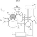
FIG. 1 shows a schematic configuration of a first embodiment of a conveyance apparatus according to the invention. -
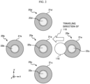
FIG. 2 shows an example of an arrangement configuration of a plurality of electromagnets in the first embodiment of the conveyance apparatus according to the invention (a comparative example (related art) also has the same configuration). -
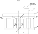
FIG. 3 is a schematic configuration diagram showing a magnetic circuit in a conveyance apparatus in the comparative example (related art). -
FIG. 4 is a schematic configuration diagram showing a magnetic circuit in the first embodiment of the conveyance apparatus according to the invention. -
FIG. 5 is a characteristic diagram showing a relationship between a current and a magnetic flux amount in the first embodiment of the conveyance apparatus according to the invention and the conveyance apparatus in the comparative example (related art). -
FIG. 6 shows a comparison of heat loss due to winding resistance between the first embodiment of the conveyance apparatus according to the invention and the conveyance apparatus in the comparative example (related art). -
FIG. 7 shows a relationship of an inductance with respect to a distance between a container carrier and an electromagnet in the first embodiment of the conveyance apparatus according to the invention. -
FIG. 8 is a schematic configuration diagram showing a magnetic circuit in a second embodiment of the conveyance apparatus according to the invention. -
FIG. 9 is a schematic configuration diagram showing a magnetic circuit in a third embodiment of the conveyance apparatus according to the invention. -
FIG. 10 shows a relationship between a current and a magnetic flux amount in the case of the third embodiment of the conveyance apparatus according to the invention and in a case where a current is caused to flow only through an electromagnet. - Hereinafter, a conveyance apparatus according to the invention will be described based on shown embodiments. In each embodiment described below, the same components are denoted by the same reference numerals. The invention is not limited to the embodiments described below, and the desired effects of the invention may be obtained even when the shape, arrangement, and other configurations are changed.
-
FIG. 1 shows a schematic configuration of a first embodiment of the conveyance apparatus according to the invention. - As shown in
FIG. 1 , aconveyance apparatus 1 in the present embodiment has a schematic configuration including afirst electromagnet 25a that forms a magnetic pole, asecond electromagnet 25b as an adjacent magnetic pole disposed adjacent to thefirst electromagnet 25a at a predetermined interval, afirst drive circuit 50a and asecond drive circuit 50b, a firstcurrent detection unit 40a and a firstcurrent detection unit 40b, acalculation unit 41, and apower supply 55. - The
first electromagnet 25a includes afirst tooth 22a formed of a magnetic body and a first winding 21a wound around an outer peripheral portion of thefirst tooth 22a. Similarly, thesecond electromagnet 25b includes asecond tooth 22b and a second winding 21b wound around an outer peripheral portion of thesecond tooth 22b. Thefirst tooth 22a and thesecond tooth 22b are cylindrical in the embodiment, but are not limited thereto, and may be prismatic, for example. - A
container carrier 110, which is a conveyed object (conveyed body), is placed at upper surface portions of thefirst electromagnet 25a and thesecond electromagnet 25b in a manner that allows movement in a horizontal direction. There is a conveyance surface (not shown) between thecontainer carrier 110 and thefirst electromagnet 25a or thesecond electromagnet 25b, and thecontainer carrier 110 slides in the horizontal direction on this conveyance surface. - A permanent magnet (not shown) forming a magnet is provided in the
container carrier 110. A neodymium alloy, ferrite, or the like is preferably used as the permanent magnet of thecontainer carrier 110. In some cases, a soft magnetic body or the like may be used instead of the permanent magnet. - Further, examples of the
container carrier 110 include a specimen holder that holds one single specimen container such as a test tube or a sample cell containing a liquid specimen, and a specimen rack that holds a plurality of specimen containers. - The first winding 21a and the second winding 21b of the
first electromagnet 25a and thesecond electromagnet 25b are respectively connected to thefirst drive circuit 50a and thesecond drive circuit 50b. - The
first electromagnet 25a and thesecond electromagnet 25b generate magnetic fields by voltages applied by thefirst drive circuit 50a and thesecond drive circuit 50b, respectively. These magnetic fields are generated upward from upper ends of thefirst tooth 22a and thesecond tooth 22b. The magnetic fields generated upward from the upper ends of thefirst tooth 22a and thesecond tooth 22b generate a thrust at the permanent magnet provided in thecontainer carrier 110. - The first
current detection unit 40a and the secondcurrent detection unit 40b have a function of detecting currents flowing through the first winding 21a and the second winding 21b of thefirst electromagnet 25a and thesecond electromagnet 25b from thefirst drive circuit 50a and thesecond drive circuit 50b, respectively, and transmitting current values detected by the firstcurrent detection unit 40a and the secondcurrent detection unit 40b to thecalculation unit 41. Thecalculation unit 41 outputs, to thefirst drive circuit 50a and thesecond drive circuit 50b, a control signal for moving thecontainer carrier 110 using the current values detected by the firstcurrent detection unit 40a and the secondcurrent detection unit 40b. Accordingly, thecontainer carrier 110 can be conveyed to a desired position. - The first
current detection unit 40a and the secondcurrent detection unit 40b may measure a voltage across a series resistor, may use a current transformer, or may use a Hall current sensor, and are not limited thereto. - The
calculation unit 41 calculates, based on the current values detected by the firstcurrent detection unit 40a and the secondcurrent detection unit 40b and the like, a relative positional relationship between each of thefirst tooth 22a and thesecond tooth 22b and thecontainer carrier 110, and calculates a position of thecontainer carrier 110 in theconveyance apparatus 1. That is, thecalculation unit 41 calculates where thecontainer carrier 110 is supposed to be currently located in theconveyance apparatus 1. Thecalculation unit 41 determines, using calculated position information of thecontainer carrier 110, a current amount necessary for driving thecontainer carrier 110 and a timing when the current is to be supplied. - The
first drive circuit 50a and thesecond drive circuit 50b are connected to thepower supply 55, and thepower supply 55 may be either AC or DC. In the case of DC, a battery may be used. -
FIG. 2 shows an example of an arrangement configuration of thefirst electromagnet 25a, thesecond electromagnet 25b and afifth electromagnet 25e that are adjacent magnetic poles disposed in a traveling direction of thecontainer carrier 110 with respect to thefirst electromagnet 25a, and athird electromagnet 25c and afourth electromagnet 25d that are adjacent magnetic poles disposed adjacent to thefirst electromagnet 25a in a normal direction of thecontainer carrier 110 in theconveyance apparatus 1 in the embodiment (an arrangement configuration of electromagnets in a comparative example (related art) to be described later is also the same arrangement configuration). InFIG. 2 , a yoke is not shown. -
FIG. 3 is a schematic configuration diagram showing a magnetic circuit in a conveyance apparatus in the comparative example (related art), andFIG. 4 is a schematic configuration diagram showing a magnetic circuit in theconveyance apparatus 1 in the first embodiment. Thefirst electromagnet 25a, thesecond electromagnet 25b, thethird electromagnet 25c, thefourth electromagnet 25d, and thefifth electromagnet 25e are adjacent to one another at intervals of a pitch A. - In the comparative example shown in
FIG. 3 and the first embodiment shown inFIG. 4 , a position directly above thefirst electromagnet 25a is a target stop position, and thecontainer carrier 110 moves on aconveyance surface 65 from the side of thethird electromagnet 25c toward thefirst electromagnet 25a. -
FIG. 5 is a characteristic diagram showing a relationship between a current and a magnetic flux amount in the conveyance apparatuses in the comparative example (indicated by a broken line) and the first embodiment (indicated by a solid line), andFIG. 6 shows a comparison of heat loss due to winding resistance between the conveyance apparatus in the comparative example and theconveyance apparatus 1 in the first embodiment. - In the comparative example shown in
FIG. 3 , a current is caused to flow only through thefirst electromagnet 25a located at the stop target position. At this time, a magnetic field generated by thefirst electromagnet 25a acts to drive thecontainer carrier 110 leftward inFIG. 3 . As thecontainer carrier 110 moves on theconveyance surface 65, amagnetic flux 71 of the permanent magnet provided in thecontainer carrier 110 links with thefirst electromagnet 25a, enhances amagnetic flux 70a generated by thefirst electromagnet 25a, thus the inside of thefirst electromagnet 25a is magnetically saturated and an inductance decreases. The position of thecontainer carrier 110 is detected using such a change in the inductance (for example, the position of thecontainer carrier 110 is specified by a value of the change in the inductance). - In the comparative example shown in
FIG. 3 , when a current of 1 p.u. flows through thefirst electromagnet 25a as shown inFIG. 5 , magnetic saturation is insufficient, and thus a magnetic flux amount Φm + Φp (Φm is magnitude of themagnetic flux 70a, and Φp is magnitude of themagnetic flux 71 of the permanent magnet) in thefirst electromagnet 25a is located at a point where a rate of change between the current and the magnetic flux is linear. - This point is a portion where the inductance does not change since there is no magnetic saturation, and accordingly, it is difficult to detect the position using the change in the inductance.
- In the comparative example shown in
FIG. 3 , when the current flowing through thefirst electromagnet 25a is increased to 2 p.u., thefirst electromagnet 25a has a magnetic flux amount of 2Φm + Φp, which operates in a region where the relationship between the current and the magnetic flux is nonlinear due to magnetic saturation and the inductance changes. Accordingly, the position can be easily detected. - However, since heat loss due to winding resistance is a product of a square of the current and resistance of the winding, as shown in
FIG. 6 , when the current is 2 p.u., the heat loss is 4 p.u., which is four times the heat loss when the current is 1 p.u. - In the present embodiment, the current flows through the
second electromagnet 25b that is adjacent to thefirst electromagnet 25a shown inFIGS. 2 and4 and is located in the conveyance direction of thecontainer carrier 110 with respect to thefirst electromagnet 25a and thefirst electromagnet 25a simultaneously. Electromagnets adjacent to thefirst electromagnet 25a include thethird electromagnet 25c, thefourth electromagnet 25d, and thefifth electromagnet 25e in addition to thesecond electromagnet 25b. - When the
third electromagnet 25c or thefourth electromagnet 25d is energized, an electromagnetic force acts on thecontainer carrier 110 in the normal direction of the conveyance direction, and thus thecontainer carrier 110 may deviate from a conveyance path (for example, thecontainer carrier 110 may move toward thethird electromagnet 25c and thefourth electromagnet 25d), resulting in abnormal conveyance. - When a current of 1 p.u. is caused to flow through the
first electromagnet 25a, a current of 1 p.u. in an opposite direction is caused to flow through thesecond electromagnet 25b. Themagnetic flux 70b generated by thesecond electromagnet 25b links with thefirst electromagnet 25a via ayoke 26 forming a magnetic circuit which also serves as a base of the electromagnet (see a downward dashed arrow indicating a magnetic flux flowing through thefirst electromagnet 25a inFIG. 4 ), and enhances themagnetic flux 70a generated by thefirst electromagnet 25a and themagnetic flux 71 of the permanent magnet. - At this time, the magnetic flux amount in the
first electromagnet 25a is Φm + Φp + Φa = 2Φm + Φp for a total current of 1 p.u. A point of this sum (indicated by P inFIG. 5 ) is a point where the relationship between the current and the magnetic flux inFIG. 5 is nonlinear due to magnetic saturation and the inductance changes. Accordingly, the position of thecontainer carrier 110 can be easily detected. - At this time, the heat loss due to the winding resistance is 1 p.u. for each of the
first electromagnet 25a and thesecond electromagnet 25b, which is a total of 2 p.u. Accordingly, the heat loss can be halved as compared with the case of the comparative example in which the current flows only through thefirst electromagnet 25a. -
FIG. 7 shows a relationship of the inductance with respect to a distance between thecontainer carrier 110 and thefirst electromagnet 25a in the first embodiment of theconveyance apparatus 1 according to the invention, where a broken line indicates a case where no current flows to an adjacent coil, and a solid line indicates a case where a current flows through the adjacent coil. - As shown in
FIG. 7 , in the first embodiment inFIG. 4 , when no current flows to the adjacent coil, the inductance changes from 1 p.u. to about 0.89 p.u., and when the adjacent coil is energized, the inductance changes from 1 p.u. to about 0.68 p.u., indicating that an amount of change in the inductance with respect to the position of thecontainer carrier 110 increases and sensitivity of position detection of thecontainer carrier 110 is improved. - As described above, the magnetic flux amount of the
first electromagnet 25a for position detection of thecontainer carrier 110 is controlled using thesecond electromagnet 25b adjacent in the traveling direction of the container carrier 110 (perform control to increase or decrease the current flowing through thesecond electromagnet 25b), and thus it is possible to improve the sensitivity of position detection while reducing heat loss without causing thecontainer carrier 110 to deviate from the conveyance path. - Further, since the current in the direction opposite to that of the
first electromagnet 25a flows through thesecond electromagnet 25b, a magnetic field that generates a repulsive force against the permanent magnet provided in thecontainer carrier 110 is generated, and this magnetic field acts as a braking force that prevents thecontainer carrier 110 from passing over thefirst electromagnet 25a that is the stop target position. - According to this embodiment, during driving of the
container carrier 110, the sensitivity of position detection of thecontainer carrier 110 in a sensorless position detection method using the magnetic saturation phenomenon can be improved while preventing an increase in the heat loss due to the winding resistance. -
FIG. 8 is a schematic configuration diagram showing a magnetic circuit in theconveyance apparatus 1 according to a second embodiment of the invention. - In the second embodiment shown in
FIG. 8 , when thefirst electromagnet 25a inFIG. 2 is the stop target position and a current flows from thethird electromagnet 25c adjacent to thefirst electromagnet 25a in the normal direction of the traveling direction of thecontainer carrier 110 toward thefirst electromagnet 25a to drive thecontainer carrier 110 on theconveyance surface 65, currents in a direction opposite to the current flowing through thefirst electromagnet 25a are caused to flow through both the adjacentthird electromagnet 25c and thefourth electromagnet 25d disposed adjacent to thefirst electromagnet 25a in the normal direction of the traveling direction of thecontainer carrier 110. At this time, it is desirable that the currents flowing through thethird electromagnet 25c and thefourth electromagnet 25d have the same magnitude. - Accordingly, a magnetic field generated by the
third electromagnet 25c and thefourth electromagnet 25d acts on thecontainer carrier 110, and an electromagnetic force acts in the normal direction relative to the conveyance direction of thecontainer carrier 110, and by causing the same current to flow through thethird electromagnet 25c and thefourth electromagnet 25d, electromagnetic forces acting in the normal direction of the conveyance direction of thecontainer carrier 110 are equal and offset. - Accordingly, the magnitude of the electromagnetic force acting in the normal direction of the conveyance direction of the
container carrier 110 is apparently zero, and thus it is possible to improve the sensitivity of position detection without causing thecontainer carrier 110 to deviate from the conveyance path. - As shown in
FIG. 8 , magnetic fluxes generated by thethird electromagnet 25c and thefourth electromagnet 25d link with thefirst electromagnet 25a via theyoke 26. At this time, themagnetic flux 70a generated by thefirst electromagnet 25a, amagnetic flux 70c generated by thethird electromagnet 25c, amagnetic flux 70d generated by thefourth electromagnet 25d, and themagnetic flux 71 of the permanent magnet have the same direction, and thus are enhanced. - In this embodiment, a current of 0.5 p.u. flows through the
first electromagnet 25a, a current of 0.25 p.u. flows through thethird electromagnet 25c, and a current of 0.25 p.u. flows through thefourth electromagnet 25d. A magnetic flux amount linked with thefirst electromagnet 25a is Φm + Φp + 0.5Φa × 2 = 2Φm + Φp for a total current of 1 p.u., which operates at a point where the inductance changes due to magnetic saturation shown in the relationship between the current and the magnetic flux inFIG. 5 . Total heat loss due to resistance of the winding at this time is 0.375 p.u. Although the same magnetic flux amount can be obtained by causing a current of 2 p.u. to flow through thefirst electromagnet 25a, the heat loss becomes 4 p.u., which indicates a large increase in the heat loss. - As described above, by supplying currents to both the
third electromagnet 25c and thefourth electromagnet 25d that are adjacent to thefirst electromagnet 25a, which performs the position detection of thecontainer carrier 110, in the normal direction of the conveyance direction of thecontainer carrier 110, it is possible to improve the sensitivity of position detection of thecontainer carrier 110 while reducing heat loss without causing thecontainer carrier 110 to deviate from the conveyance path. -
FIG. 9 is a schematic configuration diagram showing a magnetic circuit in theconveyance apparatus 1 in a third embodiment of the invention. - In the third embodiment shown in
FIG. 9 , a current in the same direction as the current flowing through thefirst electromagnet 25a flows through thesecond electromagnet 25b. At this time, since themagnetic flux 70a generated by thefirst electromagnet 25a and themagnetic flux 70b generated by thesecond electromagnet 25b cancel each other out in opposite directions, the magnetic flux amount of thefirst electromagnet 25a can be reduced. -
FIG. 10 shows a relationship between the current and the magnetic flux in a case where the current is caused to flow only through thefirst electromagnet 25a (shown by a solid line) and in the case of the third embodiment (shown by a broken line). - As shown in
FIG. 10 , in the third embodiment inFIG. 9 , when a current of 1 p.u. is caused to flow only through thefirst electromagnet 25a, the magnetic flux amount in thefirst electromagnet 25a is Φm + Φp, and due to excessive magnetic saturation, the change in the inductance is small, making it difficult to detect the position of thecontainer carrier 110. - Therefore, by energizing the
second electromagnet 25b with a current in the same direction as the current flowing through thefirst electromagnet 25a, the magnetic flux amount is reduced to Φm + Φp - Φa, and the relationship between the current and the magnetic flux is nonlinear, which operates at a point where the inductance changes, making it easier to detect the position of thecontainer carrier 110. - As described above, the sensitivity of position detection of the
container carrier 110 can be improved by reducing the magnetic flux amount of thefirst electromagnet 25a that performs position detection of thecontainer carrier 110 by the adjacentsecond electromagnet 25b. - When the
container carrier 110 passes through thefirst electromagnet 25a and moves directly above thesecond electromagnet 25b, in the case where the current flows only through thefirst electromagnet 25a, a current starts to flow through thesecond electromagnet 25b after the current of thefirst electromagnet 25a becomes 0, and thus an electromagnetic force acting on the container carrier 110 (a force that drives the container carrier 110) decreases when an energized magnetic pole is switched. Since a speed decreases as the electromagnetic force decreases, it is necessary to increase the current in order to return the speed to a speed before switching the magnetic pole. Since the current is increased, the heat loss increases. In addition, a fluctuation in the electromagnetic force increases a risk of liquid spillage due to liquid sloshing of a specimen. - However, in the third embodiment in
FIG. 9 , by causing the current to flow through thesecond electromagnet 25b simultaneously with the current flowing through thefirst electromagnet 25a, even when the current in thefirst electromagnet 25a becomes 0 at a moment when thecontainer carrier 110 passes thefirst electromagnet 25a, the electromagnetic force acts on thecontainer carrier 110 due to thesecond electromagnet 25b, and thus reduction in the force for driving thecontainer carrier 110 can be prevented. That is, the current for returning to the original speed is increased and liquid sloshing is prevented. - The invention is not limited to the embodiments described above, and includes various modifications.
- For example, the embodiments described above have been described in detail to facilitate understanding of the invention, and the invention is not necessarily limited to those including all the configurations described above. A part of a configuration of a certain embodiment can be replaced with a configuration of another embodiment, and a configuration of another embodiment can be added to a configuration of a certain embodiment. A part of a configuration of each embodiment may be added to, deleted from, or replaced with another configuration.
-
- 1... conveyance apparatus
- 21a... first winding
- 21b... second winding
- 22a... first tooth
- 22b... second tooth
- 25a... first electromagnet
- 25b... second electromagnet
- 25c... third electromagnet
- 25d... fourth electromagnet
- 25e... fifth electromagnet
- 26... yoke
- 40a... first current detection unit
- 40b... second current detection unit
- 41... calculation unit
- 50a... first drive circuit
- 50b... second drive circuit
- 55... power supply
- 65... conveyance surface
- 70a... magnetic flux generated by first electromagnet
- 70b... magnetic flux generated by second electromagnet
- 70c... magnetic flux generated by third electromagnet
- 70d... magnetic flux generated by fourth electromagnet
- 71... magnetic flux of permanent magnet
- 110... container carrier
Claims (12)
- A conveyance apparatus comprising:a magnet provided on a conveyed object side;a magnetic pole including a tooth made of a ferromagnetic body and a winding wound outside the tooth;a yoke configured to form a magnetic circuit made of a ferromagnetic body, the magnetic circuit coupling a plurality of the magnetic poles disposed adjacent to each other; anda drive circuit configured to supply a current to the winding of the magnetic pole, whereina magnetic field is generated at the magnetic pole by a voltage applied by the drive circuit, and a thrust is generated at the magnet by the magnetic field to convey a conveyed object in a horizontal direction, andthe magnetic pole includes a first magnetic pole where a current is supplied to the winding to apply a force in a conveyance direction of the conveyed object, and at least one adjacent magnetic pole disposed adjacent to the first magnetic pole at a predetermined interval, the current is supplied to a winding of at least one magnetic pole of the adjacent magnetic pole and the winding of the first magnetic pole simultaneously, and a magnetic saturation level of the first magnetic pole is controlled by a magnetic flux generated by the at least one adjacent magnetic pole.
- The conveyance apparatus according to claim 1, wherein
the at least one adjacent magnetic pole is a second magnetic pole disposed in a traveling direction of the conveyed object with respect to the first magnetic pole, the current is supplied to a winding of the second magnetic pole and the winding of the first magnetic pole simultaneously, and the magnetic saturation level of the first magnetic pole is controlled by a magnetic flux generated by the second magnetic pole. - The conveyance apparatus according to claim 2, wherein
a current in a direction opposite to that of the current supplied to the first magnetic pole is supplied to the second magnetic pole. - The conveyance apparatus according to claim 3, wherein
the current supplied to the second magnetic pole is equal in magnitude to the current supplied to the first magnetic pole. - The conveyance apparatus according to claim 2, wherein
a current in the same direction as the current supplied to the first magnetic pole is supplied to the second magnetic pole. - The conveyance apparatus according to claim 1, wherein
the at least one adjacent magnetic pole is third and fourth magnetic poles disposed adjacent to the first magnetic pole in a normal direction of a traveling direction of the conveyed object, the current is supplied to a winding of each of the third and fourth magnetic poles and the winding of the first magnetic pole simultaneously, and the magnetic saturation level of the first magnetic pole is controlled by a magnetic flux generated by the third and fourth magnetic poles. - The conveyance apparatus according to claim 6, wherein
a current in the same direction as the current supplied to the first magnetic pole is supplied to the third and fourth magnetic poles. - The conveyance apparatus according to claim 7, wherein
the current supplied to the third and fourth magnetic poles is equal in magnitude to the current supplied to the first magnetic pole. - The conveyance apparatus according to any one of claims 1 to 8, wherein
the conveyed object is held by a container carrier, the magnet is a permanent magnet provided in the container carrier, and the magnetic pole is an electromagnet. - The conveyance apparatus according to claim 9, further comprising:a current detection unit configured to detect a current flowing through a winding of the electromagnet from the drive circuit; anda calculation unit configured to output, to the drive circuit, a control signal for moving the container carrier based on a current value detected by the current detection unit.
- The conveyance apparatus according to claim 9, further comprising:a current detection unit configured to detect a current flowing through a winding of the electromagnet from the drive circuit; anda calculation unit configured to calculate a relative positional relationship between the tooth and the container carrier based on a current value detected by the current detection unit and to calculate a position of the container carrier in the conveyance apparatus.
- The conveyance apparatus according to claim 11, wherein
the calculation unit determines, using calculated position information of the container carrier, a current amount necessary for driving the container carrier and a timing when the current is to be supplied.
Applications Claiming Priority (2)
| Application Number | Priority Date | Filing Date | Title |
|---|---|---|---|
| JP2022085009A JP7825512B2 (en) | 2022-05-25 | 2022-05-25 | Conveyor |
| PCT/JP2023/013774 WO2023228583A1 (en) | 2022-05-25 | 2023-04-03 | Transport device |
Publications (2)
| Publication Number | Publication Date |
|---|---|
| EP4535650A1 true EP4535650A1 (en) | 2025-04-09 |
| EP4535650A4 EP4535650A4 (en) | 2026-06-24 |
Family
ID=88919057
Family Applications (1)
| Application Number | Title | Priority Date | Filing Date |
|---|---|---|---|
| EP23809962.6A Pending EP4535650A4 (en) | 2022-05-25 | 2023-04-03 | TRANSPORTATION DEVICE |
Country Status (5)
| Country | Link |
|---|---|
| US (1) | US20250251418A1 (en) |
| EP (1) | EP4535650A4 (en) |
| JP (1) | JP7825512B2 (en) |
| CN (1) | CN118891820A (en) |
| WO (1) | WO2023228583A1 (en) |
Family Cites Families (6)
| Publication number | Priority date | Publication date | Assignee | Title |
|---|---|---|---|---|
| EP2995580A1 (en) * | 2014-09-09 | 2016-03-16 | Roche Diagniostics GmbH | Laboratory sample distribution system and laboratory automation system |
| JP7325184B2 (en) * | 2018-12-27 | 2023-08-14 | 株式会社日立ハイテク | Transport device, sample analysis system equipped with the same, sample pretreatment device |
| JP7107866B2 (en) * | 2019-02-01 | 2022-07-27 | 株式会社日立ハイテク | Conveying device and conveying method of conveyed object |
| JP7300281B2 (en) * | 2019-03-08 | 2023-06-29 | 株式会社日立ハイテク | Transporting device, sample analysis system provided with same, sample pretreatment device, and transporting method for transported object |
| JP7323410B2 (en) * | 2019-10-01 | 2023-08-08 | 株式会社日立ハイテク | Conveyor and analysis system |
| JP7543000B2 (en) * | 2020-06-09 | 2024-09-02 | 株式会社日立ハイテク | Conveyor device and analysis system |
-
2022
- 2022-05-25 JP JP2022085009A patent/JP7825512B2/en active Active
-
2023
- 2023-04-03 CN CN202380028183.5A patent/CN118891820A/en active Pending
- 2023-04-03 US US18/856,828 patent/US20250251418A1/en active Pending
- 2023-04-03 WO PCT/JP2023/013774 patent/WO2023228583A1/en not_active Ceased
- 2023-04-03 EP EP23809962.6A patent/EP4535650A4/en active Pending
Also Published As
| Publication number | Publication date |
|---|---|
| US20250251418A1 (en) | 2025-08-07 |
| CN118891820A (en) | 2024-11-01 |
| JP2023173033A (en) | 2023-12-07 |
| EP4535650A4 (en) | 2026-06-24 |
| JP7825512B2 (en) | 2026-03-06 |
| WO2023228583A1 (en) | 2023-11-30 |
Similar Documents
| Publication | Publication Date | Title |
|---|---|---|
| EP3905515B1 (en) | Conveying device, sample analysis system and sample preprocessing device comprising same, and method for conveying sample to be conveyed | |
| EP3904889A1 (en) | Conveying device, sample analysis system comprising same, and sample preprocessing device | |
| EP4166486A1 (en) | Specimen carrying device | |
| CN115667107A (en) | Transport device and analysis system | |
| US20250251418A1 (en) | Conveyance apparatus | |
| CN114599596B (en) | Object to be conveyed, container carrier and conveying device | |
| US12565389B2 (en) | Sample conveyance system and sample conveyance method | |
| EP4418528A1 (en) | Transport device | |
| CN116568617B (en) | Sample conveying device | |
| JP7410007B2 (en) | Conveyance device | |
| CN118077138A (en) | Transport device | |
| CN118525205A (en) | Transmission device and transmission method | |
| WO2026048157A1 (en) | Electromagnetic specimen transport device, specimen analysis system, and specimen pretreatment device | |
| US12306202B2 (en) | Conveyance device | |
| WO2025216076A1 (en) | Specimen processing system | |
| WO2025134450A1 (en) | Specimen transport device, specimen analysis system, and specimen pretreatment device |
Legal Events
| Date | Code | Title | Description |
|---|---|---|---|
| STAA | Information on the status of an ep patent application or granted ep patent |
Free format text: STATUS: THE INTERNATIONAL PUBLICATION HAS BEEN MADE |
|
| PUAI | Public reference made under article 153(3) epc to a published international application that has entered the european phase |
Free format text: ORIGINAL CODE: 0009012 |
|
| STAA | Information on the status of an ep patent application or granted ep patent |
Free format text: STATUS: REQUEST FOR EXAMINATION WAS MADE |
|
| 17P | Request for examination filed |
Effective date: 20241111 |
|
| AK | Designated contracting states |
Kind code of ref document: A1 Designated state(s): AL AT BE BG CH CY CZ DE DK EE ES FI FR GB GR HR HU IE IS IT LI LT LU LV MC ME MK MT NL NO PL PT RO RS SE SI SK SM TR |
|
| DAV | Request for validation of the european patent (deleted) | ||
| DAX | Request for extension of the european patent (deleted) | ||
| A4 | Supplementary search report drawn up and despatched |
Effective date: 20260527 |
|
| RIC1 | Information provided on ipc code assigned before grant |
Ipc: H02P 25/064 20160101AFI20260520BHEP Ipc: G01N 35/04 20060101ALI20260520BHEP |