EP4535638A1 - Power conversion device - Google Patents
Power conversion device Download PDFInfo
- Publication number
- EP4535638A1 EP4535638A1 EP22944831.1A EP22944831A EP4535638A1 EP 4535638 A1 EP4535638 A1 EP 4535638A1 EP 22944831 A EP22944831 A EP 22944831A EP 4535638 A1 EP4535638 A1 EP 4535638A1
- Authority
- EP
- European Patent Office
- Prior art keywords
- wall
- side wall
- power converter
- insulating
- power conversion
- Prior art date
- Legal status (The legal status is an assumption and is not a legal conclusion. Google has not performed a legal analysis and makes no representation as to the accuracy of the status listed.)
- Pending
Links
Images












Classifications
-
- H—ELECTRICITY
- H05—ELECTRIC TECHNIQUES NOT OTHERWISE PROVIDED FOR
- H05K—PRINTED CIRCUITS; CASINGS OR CONSTRUCTIONAL DETAILS OF ELECTRIC APPARATUS; MANUFACTURE OF ASSEMBLAGES OF ELECTRICAL COMPONENTS
- H05K7/00—Constructional details common to different types of electric apparatus
- H05K7/14—Mounting supporting structure in casing or on frame or rack
- H05K7/1422—Printed circuit boards receptacles, e.g. stacked structures, electronic circuit modules or box like frames
- H05K7/1427—Housings
- H05K7/1432—Housings specially adapted for power drive units or power converters
- H05K7/14324—Housings specially adapted for power drive units or power converters comprising modular units, e.g. DIN rail mounted units
-
- H—ELECTRICITY
- H02—GENERATION; CONVERSION OR DISTRIBUTION OF ELECTRIC POWER
- H02M—APPARATUS FOR CONVERSION BETWEEN AC AND AC, BETWEEN AC AND DC, OR BETWEEN DC AND DC, AND FOR USE WITH MAINS OR SIMILAR POWER SUPPLY SYSTEMS; CONVERSION OF DC OR AC INPUT POWER INTO SURGE OUTPUT POWER; CONTROL OR REGULATION THEREOF
- H02M7/00—Conversion of AC power input into DC power output; Conversion of DC power input into AC power output
- H02M7/003—Constructional details, e.g. physical layout, assembly, wiring or busbar connections
-
- H—ELECTRICITY
- H02—GENERATION; CONVERSION OR DISTRIBUTION OF ELECTRIC POWER
- H02M—APPARATUS FOR CONVERSION BETWEEN AC AND AC, BETWEEN AC AND DC, OR BETWEEN DC AND DC, AND FOR USE WITH MAINS OR SIMILAR POWER SUPPLY SYSTEMS; CONVERSION OF DC OR AC INPUT POWER INTO SURGE OUTPUT POWER; CONTROL OR REGULATION THEREOF
- H02M7/00—Conversion of AC power input into DC power output; Conversion of DC power input into AC power output
- H02M7/42—Conversion of DC power input into AC power output without possibility of reversal
- H02M7/44—Conversion of DC power input into AC power output without possibility of reversal by static converters
- H02M7/48—Conversion of DC power input into AC power output without possibility of reversal by static converters using discharge tubes with control electrode or semiconductor devices with control electrode
- H02M7/483—Converters with outputs that each can have more than two voltages levels
- H02M7/4835—Converters with outputs that each can have more than two voltages levels comprising two or more cells, each including a switchable capacitor, the capacitors having a nominal charge voltage which corresponds to a given fraction of the input voltage, and the capacitors being selectively connected in series to determine the instantaneous output voltage
Definitions
- the present disclosure relates to a power converter.
- the present disclosure has been made in view of the above-described problem of the related art. More specifically, the present disclosure provides a power converter capable of suppressing the occurrence of electric discharge.
- the power converter of the present disclosure includes at least one insulating structure and a plurality of power conversion units.
- the at least one insulating structure includes a plurality of stacked structures stacked along a first direction.
- Each of the plurality of stacked structures has a first bottom wall, a first upper wall, a first side wall, a second side wall, and a first back wall.
- the first bottom wall and the first upper wall face each other with a space therebetween in the first direction.
- the first side wall and the second side wall face each other with a space therebetween in a second direction orthogonal to the first direction.
- An upper end and a lower end of the first side wall are connected to one end of the first bottom wall and one end of the first upper wall in the first direction, respectively.
- the first back wall is connected to one end of the first bottom wall, one end of the first side wall, and one end of the second side wall in a third direction orthogonal to the first direction and the second direction.
- the first side wall and the second side wall are divided into a plurality of portions arranged with a space therebetween in the third direction.
- the plurality of power conversion units are arranged in the first direction with a space therebetween in each of the plurality of stacked structures.
- Each of the plurality of power conversion units has a bottom surface, an upper surface, a first side surface, a second side surface, and a back surface.
- the bottom surface is in contact with the first bottom wall.
- the upper surface is separated from the first upper wall.
- the first side surface and the second side surface face one side in the second direction and the other side in the second direction, respectively.
- the back surface faces one side in the third direction.
- a corner portion between the first side surface and the back surface is covered by a corner portion between the first side wall and the first back wall.
- a corner portion between the second side surface and the back surface is covered by a corner portion between the second side wall and the first back wall.
- the power converter of the present disclosure it is possible to suppress the occurrence of electric discharge.
- a power converter according to a first embodiment will be described.
- the power converter according to the first embodiment is referred to as a power converter 100.
- the power converter 100 is, for example, a MMC (Multilevel Modular Convertor)-type HVDC (High Voltage DC) converter. However, the power converter 100 is not limited thereto.
- MMC Multilevel Modular Convertor
- HVDC High Voltage DC
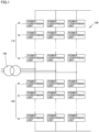
- Fig. 1 is a schematic circuit diagram of the power converter 100.
- the power converter 100 includes multiple pairs of an upper arm 110 and a lower arm 120.
- the upper arm 110 and the lower arm 120 are connected to each other in series.
- the multiple pairs of the upper arm 110 and the lower arm 120 are connected to each other in parallel.
- a transformer 130 is connected between the upper arm 110 and the lower arm 120.
- the upper arm 110 and the lower arm 120 each include a plurality of power conversion units 10 connected to each other in series.
- Fig. 2 is a schematic circuit diagram of the power conversion unit 10. As illustrated in Fig. 2 , the power conversion unit 10 includes, for example, a switching element 11a and a switching element 11b, a diode 12a and a diode 12b, a capacitor 13, and a connection line 14a and a connection line 14b.
- the power conversion unit 10 includes, for example, a switching element 11a and a switching element 11b, a diode 12a and a diode 12b, a capacitor 13, and a connection line 14a and a connection line 14b.
- Each of the switching element 11a and the switching element 11b is, for example, an IGBT (Insulated Gate Bipolar Transistor).
- the switching element 11a and the switching element 11b are connected to each other in series.
- the diode 12a is connected in parallel to the switching element 11a in a reverse bias manner, and the diode 12b is connected in parallel to the switching element 11b in a reverse bias manner.
- the capacitor 13 is connected in parallel to the switching element 11a and the switching element 11b which are connected to each other in series.
- connection line 14a is connected to an emitter of the switching element 11a and a collector of the switching element 11b.
- the connection line 14b is connected to an emitter of the switching element 11b.
- the connection line 14a of one power conversion unit 10 is connected to the connection line 14b of another adjacent power conversion unit 10.
- the power conversion unit 10 constitutes a half-bridge converter cell.
- the power conversion unit 10 may constitute a full-bridge converter cell.
- the insulating structure 20 is formed of an electrically insulating material.
- the insulating structure 20 is formed of, for example, FRP (Fiber Reinforced Plastic), glass epoxy resin, cast epoxy resin, polyethylene, vinyl chloride, silicone, fluorine synthetic rubber, nylon, electrically insulating ceramics, or the like.
- the insulating structure 20 includes a plurality of stacked structures 30.
- the side wall 33 is divided into a plurality of portions in the third direction DR3.
- the side wall 33 has a first portion 33a and a second portion 33b, for example.
- the first portion 33a and the second portion 33b are located at one end and the other end of the side wall 33 in the third direction DR3, respectively.
- the first portion 33a and the second portion 33b are separated from each other in the third direction DR3. In other words, the side wall 33 is open between the first portion 33a and the second portion 33b.
- the side wall 34 is divided into a plurality of portions in the third direction DR3.
- the side wall 34 has a first portion 34a and a second portion 34b, for example.
- the first portion 34a and the second portion 34b are located at one end and the other end of the side wall 34 in the third direction DR3, respectively.
- the first portion 34a and the second portion 34b are separated from each other in the third direction DR3. In other words, the side wall 34 is open between the first portion 34a and the second portion 34b.
- the partition wall 36 is divided into a plurality of portions in the third direction DR3.
- the partition wall 36 has a first portion 36a and a second portion 36b, for example.
- the first portion 36a and the second portion 36b are located at one end and the other end of the partition wall 36 in the third direction DR3, respectively.
- the first portion 36a and the second portion 36b are separated from each other in the third direction DR3.
- the partition wall 36 is open between the first portion 36a and the second portion 36b.
- the stacked structure 30 includes a plurality of insulating cases 40.
- the plurality of insulating cases 40 are arranged along the second direction DR2.
- Fig. 9 is a front view of the insulating case 40.
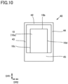
- Fig. 10 is a rear view of the insulating case 40.
- Fig. 11 is a first side view of the insulating case 40.
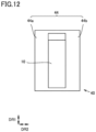
- Fig. 12 is a second side view of the insulating case 40.
- Fig. 13 is a perspective view of the insulating case 40.
- the insulating case 40 has a bottom wall 41, an upper wall 42, a side wall 43, a side wall 44, and a back wall 45.
- the bottom wall 41 and the upper wall 42 face each other with a space therebetween in the first direction DR1.
- the side wall 43 and the side wall 44 face each other with a space therebetween in the second direction DR2.
- a lower end and an upper end of the side wall 43 are connected to one end of the bottom wall 41 and one end of the upper wall 42 in the second direction DR2, respectively.
- a lower end and an upper end of the side wall 44 are connected to the other end of the bottom wall 41 and the other end of the upper wall 42 in the second direction DR2, respectively.
- the back wall 45 is connected to one end of the bottom wall 41, one end of the side wall 43, and one end of the side wall 44 in the third direction DR3.
- the back wall 45 is not connected to one end of the upper wall 42 in the third direction DR3, whereby an opening is formed between the back wall 45 and the upper wall 42.
- the side wall 43 is divided into a plurality of portions in the third direction DR3.
- the side wall 43 has a first portion 43a and a second portion 43b, for example.
- the first portion 43a and the second portion 43b are located at one end and the other end of the side wall 43 in the third direction DR3, respectively.
- the side wall 43 is divided into a plurality of portions in the third direction DR3.
- the side wall 44 has a first portion 44a and a second portion 44b, for example.
- the first portion 44a and the second portion 44b are located at one end and the other end of the side wall 44 in the third direction DR3, respectively.
- the side wall 43 of one insulating case 40 is connected to the side wall 44 of another insulating case 40 adjacent to the one insulating case 40 by an adhesive, a bolt, or the like.
- the bottom wall 41 constitutes a part of the bottom wall 31, and the upper wall 42 constitutes a part of the upper wall 32.
- the side wall 43 at one end in the second direction DR2 constitutes the side wall 33, and the side wall 44 at the other end in the second direction DR2 constitutes the side wall 34.
- the side wall 43 and the side wall 44 adjacent to each other constitute the partition wall 36.
- the power conversion unit 10 is disposed in the insulating case 40.
- the power conversion unit 10 has a bottom surface 10a and an upper surface 10b.
- the power conversion unit 10 also has a side surface 10c, a side surface 10d, and a back surface 10e.
- the bottom surface 10a, the upper surface 10b, the side surface 10c, the side surface 10d, and the back surface 10e are surfaces of a case of the power conversion unit 10.
- the case is made of metal, for example.
- the bottom surface 10a is in contact with the bottom wall 31 (the bottom wall 41).
- the upper surface 10b is spaced apart from the upper wall 32 (the upper wall 42).
- the side surface 10c and the side surface 10d face one side and the other side of the second direction DR2, respectively.
- the back surface 10e faces one side of the third direction DR3.
- a power conversion unit that is adjacent to the side wall 33 is referred to as a power conversion unit 10A.
- a power conversion unit that is adjacent to the side wall 34 is referred to as a power conversion unit 10B.
- a corner portion (a first corner portion) between the side surface 10c and the back surface 10e is covered by a corner portion (a second corner portion) between the side wall 33 and the back wall 35.
- a corner portion (a third corner portion) between the side surface 10d and the back surface 10e is covered by a corner portion (a fourth corner portion) between the side wall 34 and the back wall 35.
- the side surface 10c is separated from the side wall 33 in the second direction DR2
- the back surface 10e is separated from the back wall 35 in the third direction DR3.
- the side surface 10d is separated from the side wall 34 in the second direction DR2
- the back surface 10e is separated from the back wall 35 in the third direction DR3.
- Fig. 14 is a perspective view of the power converter 100 having a plurality of insulating structures 20.
- Fig. 15 is a first side view of the power converter 100 having a plurality of insulating structures 20.
- Fig. 16 is a second side view of the power converter 100 having a plurality of insulating structures 20.
- the power converter 100 may have a plurality of insulating structures 20.
- the power converter 100 has two insulating structures 20.
- the two insulating structures 20 are referred to as an insulating structure 20A and an insulating structure 20B.
- the insulating structure 20A and the insulating structure 20B are arranged in a back-to-back manner with a space therebetween.
- the insulating structure 20A and the insulating structure 20B are arranged in such a manner that the back walls 35 face each other with a space therebetween.
- a potential difference between two power conversion units 10 adjacent to each other in the second direction DR2 is the smallest, and a potential difference between two power conversion units 10 adjacent to each other in the third direction DR3 is the largest.
- the insulating structure 20A and the insulating structure 20B are arranged in a back-to-back manner with a space therebetween, and if the potential difference between two adjacent power conversion units 10 in the third direction DR3 is small, the insulating structure 20A and the insulating structure 20B may be disposed in a back-to-back manner without a space therebetween.
- the upper surface 10b is separated from the upper wall 32, while the bottom surface 10a is in contact with the bottom wall 31. Therefore, a portion where the bottom surface 10a and the bottom wall 31 are in contact with each other becomes a triple junction of air, metal and insulator, which may likely become a starting point of electric discharge due to the occurrence of electric field concentration. If the back wall 35 is extended to reach one end of the upper wall 32 in the third direction DR3, the withstand voltage performance is improved due to barrier insulation. However, if an insulator having a dielectric constant higher than that of air is present in the vicinity of the electric field concentration portion, the electric field at the electric field concentration portion will be stronger than that in the absence of such an insulator.
- the space between the upper wall 32 and the back wall 35 is open, an insulator is present only in the vicinity of the electrolytic concentration portion, and no insulator is present in the portion that is unlikely to become a starting point of electric discharge.
- the electric field concentration in the vicinity of the electric field concentration portion is mitigated, whereby the electric discharge is less likely to occur.
- the first corner portion and the third corner portion are likely to become starting points of electric discharge due to the occurrence of electric field concentration.
- the power converter 100 since the first corner portion and the third corner portion are covered by the second corner portion and the fourth corner portion, respectively, and the side wall 33 and the side wall 34 are divided into a plurality of portions, the insulator is present only in the vicinity of the electric field concentration portion and is not present in a portion that is unlikely to become a starting point of electric discharge. Therefore, according to the power converter 100, the electric field concentration in the vicinity of the electric field concentration portion is mitigated, whereby the electric discharge is less likely to occur.
- the power converter 400 further includes a plurality of insulating posts 60.
- the insulating post 60 is formed of an electrically insulating material.
- the insulating post 60 is formed of, for example, FRP, glass epoxy resin, the other epoxy resin, polyethylene, vinyl chloride, silicone, fluorine synthetic rubber, nylon, polymer insulator, ceramic insulator, or the like.
- the insulating post 60 extends in the first direction DR1.
- the plurality of insulating posts 60 are arranged, for example, in a grid pattern in a plan view.
- the insulating structure 20A and the insulating structure 20B are disposed on the plurality of insulating posts 60. In these regards, the configuration of the power converter 400 is different from the configuration of the power converter 100.
- a power converter according to a fifth embodiment will be described.
- the power converter according to the fifth embodiment is referred to as a power converter 500.
- the differences from the power converter 400 will be mainly described, and the description of the same components will not be repeated.
- Fig. 24 is a front view of the power converter 500.
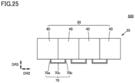
- Fig. 25 is a plan view of the power converter 500.
- Fig. 26 is an exploded perspective view of the power converter 500.
- Fig. 26 schematically illustrates two power conversion units 10, two insulating cases 40, and one conductive member 70.
- the power converter 500 includes a plurality of power conversion units 10, a plurality of insulating structures 20 (insulating structures 20A and 20B), and a plurality of insulating posts 60.
- the configuration of the power converter 500 is the same as the configuration of the power converter 400.
- the power converter 500 includes a plurality of conductive members 70 and a plurality of shield members 71. Two power conversion units 10 adjacent to each other in the second direction DR2 are electrically connected by the conductive member 70. More specifically, the conductive member 70 is connected to the connection line 14a or the connection line 14b. However, in Fig. 26 , the connection line 14a or the connection line 14b and the conductive member 70 are not illustrated. The conductive member 70 is attached to a front surface 10f of the power conversion unit 10. The conductive member 70 is attached by, for example, a bolt or an adhesive.
- the conductive member 70 is formed of an electrically conductive material.
- the conductive member 70 is formed of, for example, aluminum, copper, iron, tin, stainless steel, an alloy thereof, or another metal material.
- the conductive member 70 may be formed of a conductive plastic mixed with a carbon-based material (carbon, graphite, carbon nanotube, graphene, or the like), a conductive plastic mixed with a metal material (silver, nickel, copper, aluminum, tin, stainless steel, iron, or the like), a conductive plastic mixed with both a carbon-based material and a metal material, or the like.
- the conductive member 70 includes a first portion 70a, a second portion 70b, and a third portion 70c.
- the first portion 70a is connected to one power conversion unit 10
- the second portion 70b is connected to another power conversion unit 10 adjacent to the one power conversion unit 10 in the second direction DR2.
- the first portion 70a and the second portion 70b extend along the third direction DR3.
- the third portion 70c is connected to an end of the first portion 70a on the opposite side of the power conversion unit 10 and an end of the second portion 70b on the opposite side of the power conversion unit 10.
- the third portion 70c extends along the second direction DR2.
- the conductive member 70 is formed, for example, by bending a plate material so that it can stand on its own without coming into contact with any component of the power converter 500 or any peripheral structure.
- the conductive member 70 is not limited thereto.
- the conductive member 70 may be, for example, a braided wire.
- the shield member 71 is formed of an electrically conductive material.
- the shield member 71 includes, for example, a cylindrical portion 71a, a hemispherical portion 71b, and a hemispherical portion 71c.
- the cylindrical portion 71a has a cylindrical shape extending along the second direction DR2.
- the hemispherical portion 71b and the hemispherical portion 71c each have a hemispherical shape and are connected to both ends of the cylindrical portion 71a in the second direction DR2.
- the diameter of the hemispherical portion 71b and the hemispherical portion 71c is larger than the width of the conductive member 70.
- the shield member 71 covers a corner portion of the conductive member 70.
- the shield member 80 extends along the second direction DR2 so as to cover a corner portion between the bottom surface 10a and the front surface 10f of the power conversion unit 10C.
- the shield member 81 extends along the second direction DR2 so as to cover a corner portion between the upper surface 10b and the front surface 10f of the power conversion unit 10D.
- the shield member 80 and the shield member 81 cover a corner portion of the power conversion unit 10 facing the ground surface.
- the shield member 80 and the shield member 81 have the same potential as any of the power conversion units 10. The connection between the shield member 80 and the power conversion unit 10 is not illustrated.
- Each of the shield member 80 and the shield member 81 includes a cylindrical portion 82 having a cylindrical shape and extending along the second direction DR2, and a hemispherical portion 83 and a hemispherical portion 84 that are connected to both ends of the cylindrical portion 82.
- the shape of the shield member 80 or the shield member 81 is not limited thereto.
- Each of the shield member 80 and the shield member 81 may be, for example, a plate having rounded ends.
- Fig. 30 is a plan view of a power converter 600 according to a modification.
- both end portions of the shield member 81 may be bent along a corner portion between the upper surface 10b and the side surface 10c and a corner portion between the upper surface 10b and the side surface 10d in the power conversion unit 10D in order to protect the corner portions of the power conversion unit 10D.
- both end portions of the shield member 80 may also be bent along a corner portion between the bottom surface 10a and the side surface 10c and a corner portion between the bottom surface 10a and the side surface 10d in the power conversion unit 10C in order to protect the corner portions of the power conversion unit 10C.
- the shield member 80 and the shield member 81 are formed of an electrically conductive material.
- the shield member 80 and the shield member 81 are formed of, for example, aluminum, copper, iron, tin, stainless steel, alloys thereof, or other metal materials.
- the shield member 80 and the shield member 81 may be formed of a conductive plastic mixed with a carbon-based material (carbon, graphite, carbon nanotube, graphene, or the like), a conductive plastic mixed with a metal material (silver, nickel, copper, aluminum, tin, stainless steel, iron, or the like), a conductive plastic mixed with both a carbon-based material and a metal material, or the like.
- the configuration of the power converter 600 is different from the configuration of the power converter 500.
- an electric discharge may occur from a corner portion of the power conversion unit 10C or a corner portion of the power conversion unit 10D toward a ground object.
- the power converter 600 since the corner portions of the power conversion unit 10C and the power conversion unit 10D are covered by the shield member 80 and the shield member 81, the electric field concentration at the corner portions is mitigated, which makes it possible to suppress the occurrence of electric discharge as described above.
- 10, 10A, 10B, 10C, 10D power conversion unit; 10a: bottom surface; 10b: upper surface; 10c, 10d: side surface; 10e: back surface; 10f: front surface; 11a, 11b: switching element; 12a, 12b: diode; 13: capacitor; 14a, 14b: connection line; 20, 20A, 20B: insulating structure; 30, 30A, 30B: stacked structure; 31: bottom wall; 32: upper wall; 33: side wall; 33a: first portion; 33b: second portion; 34: side wall; 34a: first portion; 34b: second portion; 35: back wall; 36: partition wall; 36a: first portion; 36b: second portion; 40: insulating case; 41: bottom wall; 42: upper wall; 43: side wall; 43a: first portion; 43b: second portion; 44: side wall; 44a: first portion; 44b: second portion; 45: back wall; 50: insulating connection member; 60: insulating post; 70: conductive member; 70a: first portion; 70
Landscapes
- Engineering & Computer Science (AREA)
- Microelectronics & Electronic Packaging (AREA)
- Inverter Devices (AREA)
Abstract
Description
- The present disclosure relates to a power converter.
- For example,
Japanese Patent No. 6995259 - PTL 1:
Japanese Patent No. 6995259 - However, in the power converter described in PTL 1, there is room for improvement in suppressing the occurrence of electric discharge. The present disclosure has been made in view of the above-described problem of the related art. More specifically, the present disclosure provides a power converter capable of suppressing the occurrence of electric discharge.
- The power converter of the present disclosure includes at least one insulating structure and a plurality of power conversion units. The at least one insulating structure includes a plurality of stacked structures stacked along a first direction. Each of the plurality of stacked structures has a first bottom wall, a first upper wall, a first side wall, a second side wall, and a first back wall. The first bottom wall and the first upper wall face each other with a space therebetween in the first direction. The first side wall and the second side wall face each other with a space therebetween in a second direction orthogonal to the first direction. An upper end and a lower end of the first side wall are connected to one end of the first bottom wall and one end of the first upper wall in the first direction, respectively. An upper end and a lower end of the second side wall are connected to the other end of the first bottom wall and the other end of the first upper wall in the first direction, respectively. The first back wall is connected to one end of the first bottom wall, one end of the first side wall, and one end of the second side wall in a third direction orthogonal to the first direction and the second direction. The first side wall and the second side wall are divided into a plurality of portions arranged with a space therebetween in the third direction. The plurality of power conversion units are arranged in the first direction with a space therebetween in each of the plurality of stacked structures. Each of the plurality of power conversion units has a bottom surface, an upper surface, a first side surface, a second side surface, and a back surface. The bottom surface is in contact with the first bottom wall. The upper surface is separated from the first upper wall. The first side surface and the second side surface face one side in the second direction and the other side in the second direction, respectively. The back surface faces one side in the third direction. In a first power conversion unit of the plurality of power conversion units that is adjacent to the first side wall, a corner portion between the first side surface and the back surface is covered by a corner portion between the first side wall and the first back wall. In a second power conversion unit of the plurality of power conversion units that is adjacent to the second side wall, a corner portion between the second side surface and the back surface is covered by a corner portion between the second side wall and the first back wall.
- According to the power converter of the present disclosure, it is possible to suppress the occurrence of electric discharge.
-
-
Fig. 1 is a schematic circuit diagram of apower converter 100; -
Fig. 2 is a schematic circuit diagram of thepower conversion unit 10; -
Fig. 3 is a front view of thepower converter 100; -
Fig. 4 is a rear view of thepower converter 100; -
Fig. 5 is a first side view of thepower converter 100; -
Fig. 6 is a second side view of thepower converter 100; -
Fig. 7 is a cross-sectional view taken along line VII-VII inFig. 3 ; -
Fig. 8 is a perspective view of thepower converter 100; -
Fig. 9 is a front view of aninsulating case 40; -
Fig. 10 is a rear view of theinsulating case 40; -
Fig. 11 is a first side view of theinsulating case 40; -
Fig. 12 is a second side view of theinsulating case 40; -
Fig. 13 is a perspective view of theinsulating case 40; -
Fig. 14 is a perspective view of thepower converter 100 having a plurality ofinsulating structures 20; -
Fig. 15 is a first side view of thepower converter 100 having a plurality ofinsulating structures 20; -
Fig. 16 is a second side view of thepower converter 100 having a plurality ofinsulating structures 20; -
Fig. 17 is a perspective view of aninsulating case 40 in apower converter 100A; -
Fig. 18 is a graph illustrating an intensity of an electric field at a ridge line between abottom surface 10a and aside surface 10c; -
Fig. 19 is a perspective view of apower converter 200; -
Fig. 20 is a side view of thepower converter 200; -
Fig. 21 is a perspective view of apower converter 300; -
Fig. 22 is a rear view of aninsulating structure 20 in thepower converter 300; -
Fig. 23 is a perspective view of apower converter 400; -
Fig. 24 is a front view of apower converter 500; -
Fig. 25 is a plan view of thepower converter 500; -
Fig. 26 is an exploded perspective view of thepower converter 500; -
Fig. 27A is a perspective view illustrating the position of a maximum electric field portion in aconductive member 70 when ashield member 71 is provided; -
Fig. 27B is a perspective view illustrating the position of a maximum electric field portion in aconductive member 70 when ashield member 71 is not provided; -
Fig. 28 is a perspective view of apower converter 600; -
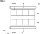
Fig. 29 is a plan view of thepower converter 600; and -
Fig. 30 is a plan view of thepower converter 600 according to a modification. - Embodiments of the present disclosure will be described in detail with reference to the drawings. In the following drawings, the same or corresponding parts are denoted by the same reference numerals, and the description will not be repeated.
- A power converter according to a first embodiment will be described. The power converter according to the first embodiment is referred to as a
power converter 100. - Hereinafter, the configuration of the
power converter 100 will be described. - The
power converter 100 is, for example, a MMC (Multilevel Modular Convertor)-type HVDC (High Voltage DC) converter. However, thepower converter 100 is not limited thereto. -
Fig. 1 is a schematic circuit diagram of thepower converter 100. As illustrated inFig. 1 , thepower converter 100 includes multiple pairs of anupper arm 110 and alower arm 120. Theupper arm 110 and thelower arm 120 are connected to each other in series. The multiple pairs of theupper arm 110 and thelower arm 120 are connected to each other in parallel. Atransformer 130 is connected between theupper arm 110 and thelower arm 120. Theupper arm 110 and thelower arm 120 each include a plurality ofpower conversion units 10 connected to each other in series. -
Fig. 2 is a schematic circuit diagram of thepower conversion unit 10. As illustrated inFig. 2 , thepower conversion unit 10 includes, for example, aswitching element 11a and aswitching element 11b, adiode 12a and adiode 12b, acapacitor 13, and aconnection line 14a and aconnection line 14b. - Each of the
switching element 11a and theswitching element 11b is, for example, an IGBT (Insulated Gate Bipolar Transistor). The switchingelement 11a and theswitching element 11b are connected to each other in series. - The
diode 12a is connected in parallel to theswitching element 11a in a reverse bias manner, and thediode 12b is connected in parallel to theswitching element 11b in a reverse bias manner. Thecapacitor 13 is connected in parallel to theswitching element 11a and theswitching element 11b which are connected to each other in series. - The
connection line 14a is connected to an emitter of theswitching element 11a and a collector of theswitching element 11b. Theconnection line 14b is connected to an emitter of theswitching element 11b. Theconnection line 14a of onepower conversion unit 10 is connected to theconnection line 14b of another adjacentpower conversion unit 10. Thus, thepower conversion unit 10 constitutes a half-bridge converter cell. Thepower conversion unit 10 may constitute a full-bridge converter cell. -
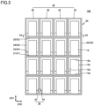
Fig. 3 is a front view of thepower converter 100.Fig. 4 is a rear view of thepower converter 100.Fig. 5 is a first side view of thepower converter 100.Fig. 6 is a second side view of thepower converter 100.Fig. 7 is a cross-sectional view taken along line VII-VII inFig. 3 .Fig. 8 is a perspective view of thepower converter 100. As illustrated inFigs. 3 to 8 , thepower converter 100 includes an insulatingstructure 20. - The insulating
structure 20 is formed of an electrically insulating material. The insulatingstructure 20 is formed of, for example, FRP (Fiber Reinforced Plastic), glass epoxy resin, cast epoxy resin, polyethylene, vinyl chloride, silicone, fluorine synthetic rubber, nylon, electrically insulating ceramics, or the like. The insulatingstructure 20 includes a plurality ofstacked structures 30. - The plurality of
stacked structures 30 are stacked in a first direction DR1. The first direction DR1 corresponds to, for example, the vertical direction. The stackedstructure 30 includes abottom wall 31, anupper wall 32, aside wall 33, aside wall 34, aback wall 35, and a plurality ofpartition walls 36. Theupper wall 32 of one stackedstructure 30 is connected to thebottom wall 31 of another stackedstructure 30 adjacent to the one stackedstructure 30 by an adhesive, a bolt, or the like. - The
bottom wall 31 and theupper wall 32 face each other with a space therebetween in the first direction DR1. Theside wall 33 and theside wall 34 face each other with a space therebetween in a second direction DR2. The second direction DR2 is orthogonal to the first direction DR1. The second direction DR2 corresponds to, for example, the horizontal direction. A lower end and an upper end of theside wall 33 are connected to one end (the right end inFig. 3 ) of thebottom wall 31 and one end of theupper wall 32 in the second direction DR2, respectively. A lower end and an upper end of theside wall 34 are connected to the other end (the left end inFig. 3 ) of thebottom wall 31 and the other end of theupper wall 32 in the second direction DR2, respectively. - A third direction DR3 is orthogonal to the first direction DR1 and the second direction DR2, and corresponds to, for example, the horizontal direction. The
back wall 35 is connected to one end (the right end inFig. 5 ) of thebottom wall 31, one end of theside wall 33, and one end of theside wall 34 in the third direction DR3. However, theback wall 35 is not connected to one end of theupper wall 32 in the third direction DR3, whereby an opening is formed between theback wall 35 and theupper wall 32. The plurality ofpartition walls 36 are arranged between theside wall 33 and theside wall 34 in the second direction DR2. A lower end and an upper end of thepartition wall 36 are connected to thebottom wall 31 and theupper wall 32, respectively. One end of thepartition wall 36 in the third direction DR3 is connected to theback wall 35. - The
power conversion unit 10 is disposed in a space defined by thebottom wall 31, theupper wall 32, theside wall 33, theback wall 35 and thepartition wall 36, a space defined by thebottom wall 31, theupper wall 32, theside wall 34, theback wall 35 and thepartition wall 36, and a space defined by thebottom wall 31, theupper wall 32, theback wall 35 and twoadjacent partition walls 36, respectively. In other words, a plurality ofpower conversion units 10 are arranged in the second direction DR2 inside the stackedstructure 30. Two of thepower conversion units 10 that are adjacent to each other in the second direction DR2 are electrically connected to each other. One power conversion unit 10 (apower conversion unit 10A or apower conversion unit 10B to be described later) at one side or the other side of the second direction DR2 may be also electrically connected to apower conversion unit 10 other than the adjacentpower conversion unit 10 in the second direction DR2. - The
side wall 33 is divided into a plurality of portions in the third direction DR3. Theside wall 33 has afirst portion 33a and asecond portion 33b, for example. Thefirst portion 33a and thesecond portion 33b are located at one end and the other end of theside wall 33 in the third direction DR3, respectively. Thefirst portion 33a and thesecond portion 33b are separated from each other in the third direction DR3. In other words, theside wall 33 is open between thefirst portion 33a and thesecond portion 33b. - The
side wall 34 is divided into a plurality of portions in the third direction DR3. Theside wall 34 has afirst portion 34a and asecond portion 34b, for example. Thefirst portion 34a and thesecond portion 34b are located at one end and the other end of theside wall 34 in the third direction DR3, respectively. Thefirst portion 34a and thesecond portion 34b are separated from each other in the third direction DR3. In other words, theside wall 34 is open between thefirst portion 34a and thesecond portion 34b. - The
partition wall 36 is divided into a plurality of portions in the third direction DR3. Thepartition wall 36 has a first portion 36a and a second portion 36b, for example. The first portion 36a and the second portion 36b are located at one end and the other end of thepartition wall 36 in the third direction DR3, respectively. The first portion 36a and the second portion 36b are separated from each other in the third direction DR3. In other words, thepartition wall 36 is open between the first portion 36a and the second portion 36b. - The stacked
structure 30 includes a plurality of insulatingcases 40. The plurality of insulatingcases 40 are arranged along the second direction DR2.Fig. 9 is a front view of the insulatingcase 40.Fig. 10 is a rear view of the insulatingcase 40.Fig. 11 is a first side view of the insulatingcase 40.Fig. 12 is a second side view of the insulatingcase 40.Fig. 13 is a perspective view of the insulatingcase 40. As illustrated inFigs. 10 to 13 , the insulatingcase 40 has abottom wall 41, anupper wall 42, aside wall 43, aside wall 44, and aback wall 45. - The
bottom wall 41 and theupper wall 42 face each other with a space therebetween in the first direction DR1. Theside wall 43 and theside wall 44 face each other with a space therebetween in the second direction DR2. A lower end and an upper end of theside wall 43 are connected to one end of thebottom wall 41 and one end of theupper wall 42 in the second direction DR2, respectively. A lower end and an upper end of theside wall 44 are connected to the other end of thebottom wall 41 and the other end of theupper wall 42 in the second direction DR2, respectively. Theback wall 45 is connected to one end of thebottom wall 41, one end of theside wall 43, and one end of theside wall 44 in the third direction DR3. Theback wall 45 is not connected to one end of theupper wall 42 in the third direction DR3, whereby an opening is formed between theback wall 45 and theupper wall 42. - The
side wall 43 is divided into a plurality of portions in the third direction DR3. Theside wall 43 has afirst portion 43a and asecond portion 43b, for example. Thefirst portion 43a and thesecond portion 43b are located at one end and the other end of theside wall 43 in the third direction DR3, respectively. Theside wall 43 is divided into a plurality of portions in the third direction DR3. Theside wall 44 has afirst portion 44a and asecond portion 44b, for example. Thefirst portion 44a and thesecond portion 44b are located at one end and the other end of theside wall 44 in the third direction DR3, respectively. - The
side wall 43 of one insulatingcase 40 is connected to theside wall 44 of another insulatingcase 40 adjacent to the one insulatingcase 40 by an adhesive, a bolt, or the like. Thebottom wall 41 constitutes a part of thebottom wall 31, and theupper wall 42 constitutes a part of theupper wall 32. Theside wall 43 at one end in the second direction DR2 constitutes theside wall 33, and theside wall 44 at the other end in the second direction DR2 constitutes theside wall 34. Theside wall 43 and theside wall 44 adjacent to each other constitute thepartition wall 36. Thepower conversion unit 10 is disposed in the insulatingcase 40. - The
power conversion unit 10 has abottom surface 10a and anupper surface 10b. Thepower conversion unit 10 also has aside surface 10c, aside surface 10d, and aback surface 10e. Thebottom surface 10a, theupper surface 10b, theside surface 10c, theside surface 10d, and theback surface 10e are surfaces of a case of thepower conversion unit 10. The case is made of metal, for example. Thebottom surface 10a is in contact with the bottom wall 31 (the bottom wall 41). Theupper surface 10b is spaced apart from the upper wall 32 (the upper wall 42). Theside surface 10c and theside surface 10d face one side and the other side of the second direction DR2, respectively. Theback surface 10e faces one side of the third direction DR3. - Among the plurality of
power conversion units 10 disposed inside the stackedstructure 30, a power conversion unit that is adjacent to theside wall 33 is referred to as apower conversion unit 10A. Among the plurality ofpower conversion units 10 disposed inside the stackedstructure 30, a power conversion unit that is adjacent to theside wall 34 is referred to as apower conversion unit 10B. - In the
power conversion unit 10A, a corner portion (a first corner portion) between theside surface 10c and theback surface 10e is covered by a corner portion (a second corner portion) between theside wall 33 and theback wall 35. In thepower conversion unit 10B, a corner portion (a third corner portion) between theside surface 10d and theback surface 10e is covered by a corner portion (a fourth corner portion) between theside wall 34 and theback wall 35. Preferably, in thepower conversion unit 10A, theside surface 10c is separated from theside wall 33 in the second direction DR2, and theback surface 10e is separated from theback wall 35 in the third direction DR3. Preferably, in thepower conversion unit 10B, theside surface 10d is separated from theside wall 34 in the second direction DR2, and theback surface 10e is separated from theback wall 35 in the third direction DR3. -
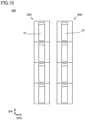
Fig. 14 is a perspective view of thepower converter 100 having a plurality of insulatingstructures 20.Fig. 15 is a first side view of thepower converter 100 having a plurality of insulatingstructures 20.Fig. 16 is a second side view of thepower converter 100 having a plurality of insulatingstructures 20. As illustrated inFigs. 14 to 16 , thepower converter 100 may have a plurality of insulatingstructures 20. In the example illustrated inFigs. 14 to 16 , thepower converter 100 has two insulatingstructures 20. The two insulatingstructures 20 are referred to as an insulatingstructure 20A and an insulatingstructure 20B. The insulatingstructure 20A and the insulatingstructure 20B are arranged in a back-to-back manner with a space therebetween. In other words, the insulatingstructure 20A and the insulatingstructure 20B are arranged in such a manner that theback walls 35 face each other with a space therebetween. - In the examples illustrated in
Figs. 14 to 16 , a potential difference between twopower conversion units 10 adjacent to each other in the second direction DR2 is the smallest, and a potential difference between twopower conversion units 10 adjacent to each other in the third direction DR3 is the largest. In the examples illustrated inFigs. 14 to 16 , the insulatingstructure 20A and the insulatingstructure 20B are arranged in a back-to-back manner with a space therebetween, and if the potential difference between two adjacentpower conversion units 10 in the third direction DR3 is small, the insulatingstructure 20A and the insulatingstructure 20B may be disposed in a back-to-back manner without a space therebetween. - The effects of the
power converter 100 will be described below. - As described above, the
upper surface 10b is separated from theupper wall 32, while thebottom surface 10a is in contact with thebottom wall 31. Therefore, a portion where thebottom surface 10a and thebottom wall 31 are in contact with each other becomes a triple junction of air, metal and insulator, which may likely become a starting point of electric discharge due to the occurrence of electric field concentration. If theback wall 35 is extended to reach one end of theupper wall 32 in the third direction DR3, the withstand voltage performance is improved due to barrier insulation. However, if an insulator having a dielectric constant higher than that of air is present in the vicinity of the electric field concentration portion, the electric field at the electric field concentration portion will be stronger than that in the absence of such an insulator. - In the
power converter 100, since the space between theupper wall 32 and theback wall 35 is open, an insulator is present only in the vicinity of the electrolytic concentration portion, and no insulator is present in the portion that is unlikely to become a starting point of electric discharge. As a result, according to thepower converter 100, the electric field concentration in the vicinity of the electric field concentration portion is mitigated, whereby the electric discharge is less likely to occur. - Since the
back surface 10e is facing anotherpower conversion unit 10 having the largest potential difference, the first corner portion and the third corner portion are likely to become starting points of electric discharge due to the occurrence of electric field concentration. In thepower converter 100, since the first corner portion and the third corner portion are covered by the second corner portion and the fourth corner portion, respectively, and theside wall 33 and theside wall 34 are divided into a plurality of portions, the insulator is present only in the vicinity of the electric field concentration portion and is not present in a portion that is unlikely to become a starting point of electric discharge. Therefore, according to thepower converter 100, the electric field concentration in the vicinity of the electric field concentration portion is mitigated, whereby the electric discharge is less likely to occur. - A power converter according to a comparative example is referred to as a
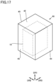
power converter 100A. The configuration of thepower converter 100A is the same as the configuration of thepower converter 100 except for the insulatingcase 40.Fig. 17 is a perspective view of the insulatingcase 40 in thepower converter 100A. As illustrated inFig. 17 , in the insulatingcase 40 of thepower converter 100A, theside wall 43 and theside wall 44 are not divided into a plurality of portions. Moreover, in the insulatingcase 40 of thepower converter 100A, theback wall 45 extends to reach one end of theupper wall 42 in the third direction DR3. -
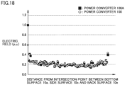
Fig. 18 is a graph illustrating an intensity of an electric field at a ridge line between thebottom surface 10a and theside surface 10c. The vertical axis inFig. 18 indicates a strength of an electric field at the ridge line between thebottom surface 10a and theside surface 10c. The horizontal axis inFig. 18 indicates a distance from an intersection point between thebottom surface 10a, theside surface 10c and theback surface 10e. As illustrated inFig. 18 , in thepower converter 100 and thepower converter 100A, the intersection point between thebottom surface 10a, theside surface 10c and theback surface 10e is an electric field concentration point. However, in thepower converter 100, the strength of the electric field at the electric field concentration portion is mitigated as compared with thepower converter 100. As described above, in thepower converter 100, the electric field concentration in the vicinity of the electric field concentration portion is mitigated, whereby the electric discharge is less likely to occur. - A power converter according to a second embodiment will be described. The power converter according to the second embodiment is referred to as a
power converter 200. In the present embodiment, the differences from thepower converter 100 will be mainly described, and the description of the same components will not be repeated. - Hereinafter, the configuration of the
power converter 200 will be described. -
Fig. 19 is a perspective view of thepower converter 200.Fig. 20 is a side view of thepower converter 200. As illustrated inFigs. 19 and20 , thepower converter 200 includes a plurality ofpower conversion units 10 and a plurality of insulating structures 20 (insulatingstructures power converter 200 is the same as the configuration of thepower converter 100. - The
power converter 200 further includes a plurality of insulatingconnection members 50. The insulatingconnection member 50 is formed of an electrically insulating material. The insulatingconnection member 50 connects the insulatingstructure 20A and the insulatingstructure 20B. More specifically, the insulatingconnection member 50 connects each of the plurality ofstacked structures 30 constituting the insulatingstructure 20A and each of the plurality ofstacked structures 30 constituting the insulatingstructure 20B. A part of the plurality ofstacked structures 30 constituting the insulatingstructure 20A may not be connected to a part of the plurality ofstacked structures 30 constituting the insulatingstructure 20B by the insulatingconnection member 50. In these regards, the configuration of thepower converter 200 is different from the configuration of thepower converter 100. - The effects of the
power converter 200 will be described below. - In the
power converter 200, since the insulatingstructure 20A and the insulatingstructure 20B are connected by the insulatingconnection member 50, the distance between the insulatingstructure 20A and the insulatingstructure 20B is mechanically kept constant. Therefore, even if a vibration such as an earthquake or the like is applied to the power converter, the insulation distance between the insulatingstructure 20A and the insulatingstructure 20B is prevented from becoming smaller than expected. - A power converter according to a third embodiment will be described. The power converter according to the third embodiment is referred to as a
power converter 200. In the present embodiment, the differences from thepower converter 200 will be mainly described, and the description of the same components will not be repeated. - Hereinafter, the configuration of the
power converter 300 will be described. -
Fig. 21 is a perspective view of thepower converter 300.Fig. 22 is a rear view of the insulatingstructure 20 in thepower converter 300. As illustrated inFigs. 21 and22 , thepower converter 300 includes a plurality ofpower conversion units 10, a plurality of insulating structures 20 (insulatingstructures connection members 50. In this regard, the configuration of thepower converter 300 is the same as the configuration of thepower converter 200. - In the
power converter 300, the stackedstructure 30 includes abottom wall 31, anupper wall 32, aside wall 33, aside wall 34, and aback wall 35, but does not include apartition wall 36 and is not constituted by the plurality of insulatingcases 40. In this regard, the configuration of thepower converter 300 is different from the configuration of thepower converter 200. In the example illustrated inFigs. 21 and22 , the stackedstructure 30 does not include apartition wall 36, but thepartition wall 36 may be disposed in a portion between twopower conversion units 10 adjacent to each other in the second direction DR2. - The effects of the
power converter 300 will be described below. - The potential difference between the two adjacent
power conversion units 10 is the smallest in the second direction DR2 between the two adjacentpower conversion units 10. When the potential difference between the two adjacentpower conversion units 10 in the second direction DR2 is small, even if thepartition wall 36 is not disposed, it is possible to suppress the dielectric breakdown between the two adjacentpower conversion units 10 in the second direction DR2. Therefore, in thepower converter 300, it is possible to suppress the dielectric breakdown between twopower conversion units 10 adjacent to each other in the second direction DR2 while reducing the weight of the stackedstructure 30. - A power converter according to a fourth embodiment will be described. The power converter according to the fourth embodiment is referred to as a
power converter 400. In the present embodiment, the differences from thepower converter 100 will be mainly described, and the description of the same components will not be repeated. - Hereinafter, the configuration of the
power converter 400 will be described. -
Fig. 23 is a perspective view of thepower converter 400. As illustrated inFig. 23 , thepower converter 400 includes a plurality ofpower conversion units 10 and a plurality of insulating structures 20 (insulatingstructures power converter 400 is the same as the configuration of thepower converter 100. - The
power converter 400 further includes a plurality of insulatingposts 60. The insulatingpost 60 is formed of an electrically insulating material. The insulatingpost 60 is formed of, for example, FRP, glass epoxy resin, the other epoxy resin, polyethylene, vinyl chloride, silicone, fluorine synthetic rubber, nylon, polymer insulator, ceramic insulator, or the like. The insulatingpost 60 extends in the first direction DR1. The plurality of insulatingposts 60 are arranged, for example, in a grid pattern in a plan view. The insulatingstructure 20A and the insulatingstructure 20B are disposed on the plurality of insulatingposts 60. In these regards, the configuration of thepower converter 400 is different from the configuration of thepower converter 100. - Hereinafter, the effects of the
power converter 400 will be described. - When a surge voltage is applied due to a failure during operation, an operation of a peripheral device, a lightning strike or the like, an electric discharge may occur from the
power conversion unit 10 toward a ground object. In thepower converter 400, since the insulatingstructure 20A and the insulatingstructure 20B are supported by the plurality ofinsulation posts 60 to secure the distance between thepower conversion unit 10 and the ground, it is possible to suppress the occurrence of an electric discharge as described above. - A power converter according to a fifth embodiment will be described. The power converter according to the fifth embodiment is referred to as a
power converter 500. In the present embodiment, the differences from thepower converter 400 will be mainly described, and the description of the same components will not be repeated. - Hereinafter, the configuration of the
power converter 500 will be described. -
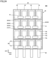
Fig. 24 is a front view of thepower converter 500.Fig. 25 is a plan view of thepower converter 500.Fig. 26 is an exploded perspective view of thepower converter 500.Fig. 26 schematically illustrates twopower conversion units 10, two insulatingcases 40, and oneconductive member 70. As illustrated inFigs. 24 to 26 , thepower converter 500 includes a plurality ofpower conversion units 10, a plurality of insulating structures 20 (insulatingstructures posts 60. In this regard, the configuration of thepower converter 500 is the same as the configuration of thepower converter 400. - The
power converter 500 includes a plurality ofconductive members 70 and a plurality ofshield members 71. Twopower conversion units 10 adjacent to each other in the second direction DR2 are electrically connected by theconductive member 70. More specifically, theconductive member 70 is connected to theconnection line 14a or theconnection line 14b. However, inFig. 26 , theconnection line 14a or theconnection line 14b and theconductive member 70 are not illustrated. Theconductive member 70 is attached to afront surface 10f of thepower conversion unit 10. Theconductive member 70 is attached by, for example, a bolt or an adhesive. - The
conductive member 70 is formed of an electrically conductive material. Theconductive member 70 is formed of, for example, aluminum, copper, iron, tin, stainless steel, an alloy thereof, or another metal material. Theconductive member 70 may be formed of a conductive plastic mixed with a carbon-based material (carbon, graphite, carbon nanotube, graphene, or the like), a conductive plastic mixed with a metal material (silver, nickel, copper, aluminum, tin, stainless steel, iron, or the like), a conductive plastic mixed with both a carbon-based material and a metal material, or the like. - The
conductive member 70 includes afirst portion 70a, asecond portion 70b, and athird portion 70c. Thefirst portion 70a is connected to onepower conversion unit 10, and thesecond portion 70b is connected to anotherpower conversion unit 10 adjacent to the onepower conversion unit 10 in the second direction DR2. Thefirst portion 70a and thesecond portion 70b extend along the third direction DR3. Thethird portion 70c is connected to an end of thefirst portion 70a on the opposite side of thepower conversion unit 10 and an end of thesecond portion 70b on the opposite side of thepower conversion unit 10. Thethird portion 70c extends along the second direction DR2. - The
conductive member 70 is formed, for example, by bending a plate material so that it can stand on its own without coming into contact with any component of thepower converter 500 or any peripheral structure. However, theconductive member 70 is not limited thereto. Theconductive member 70 may be, for example, a braided wire. - The
shield member 71 is formed of an electrically conductive material. Theshield member 71 includes, for example, acylindrical portion 71a, ahemispherical portion 71b, and ahemispherical portion 71c. Thecylindrical portion 71a has a cylindrical shape extending along the second direction DR2. Thehemispherical portion 71b and thehemispherical portion 71c each have a hemispherical shape and are connected to both ends of thecylindrical portion 71a in the second direction DR2. The diameter of thehemispherical portion 71b and thehemispherical portion 71c is larger than the width of theconductive member 70. Theshield member 71 covers a corner portion of theconductive member 70. More specifically, a corner portion between thefirst portion 70a and thethird portion 70c is covered by thehemispherical portion 71b, and a corner portion between thesecond portion 70b and thethird portion 70c is covered by thehemispherical portion 71c. In these regards, the configuration of thepower converter 500 is different from the configuration of thepower converter 400. - The effects of the
power converter 500 will be described below. - Since the
conductive member 70 protrudes outside from thepower converter 500, the electric field concentration is likely to occur at a corner portion of theconductive member 70 when a voltage is applied to thepower conversion unit 10. In thepower converter 500, since the corner portion of theconductive member 70 is covered by theshield member 71, the electric field concentration at the corner portion of theconductive member 70 can be mitigated.Fig. 27A is a perspective view illustrating the position of a maximum electric field portion in theconductive member 70 when theshield member 71 is provided.Fig. 27B is a perspective view illustrating the position of a maximum electric field portion in theconductive member 70 when theshield member 71 is not provided. InFigs. 27A and27B , the position of the maximum electric field portion in theconductive member 70 is indicated by an arrow. As an example, in thepower converter 500, the strength of the electric field in the maximum electric field portion in theconductive member 70 can be reduced to about one third of that in the case where theshield member 71 is not provided. - A power converter according to a sixth embodiment will be described. The power converter according to the sixth embodiment is referred to as a
power converter 600. In the present embodiment, the differences from thepower converter 400 will be mainly described, and the description of the same components will not be repeated. - Hereinafter, the configuration of the
power converter 600 will be described. -
Fig. 28 is a perspective view of thepower converter 600.Fig. 29 is a plan view of thepower converter 600. As illustrated inFigs. 28 and29 , thepower converter 600 includes a plurality ofpower conversion units 10, a plurality of insulating structures 20 (insulatingstructures posts 60. In this regard, the configuration of thepower converter 600 is the same as the configuration of thepower converter 400. - The
power converter 600 includes a plurality ofshield members 80 and a plurality ofshield members 81. Among the plurality ofstacked structures 30 constituting the insulatingstructure 20, a stacked structure that is closest to the insulatingpost 60 is referred to as astacked structure 30A. Among the plurality ofstacked structures 30 constituting the insulatingstructure 20, a stacked structure that is farthest away from the insulatingpost 60 is referred to as astacked structure 30B. Thepower conversion unit 10 disposed inside thestacked structure 30A is referred to as apower conversion unit 10C. Thepower conversion unit 10 disposed inside thestacked structure 30B is referred to as apower conversion unit 10D. - The
shield member 80 extends along the second direction DR2 so as to cover a corner portion between thebottom surface 10a and thefront surface 10f of thepower conversion unit 10C. Theshield member 81 extends along the second direction DR2 so as to cover a corner portion between theupper surface 10b and thefront surface 10f of thepower conversion unit 10D. In other words, theshield member 80 and theshield member 81 cover a corner portion of thepower conversion unit 10 facing the ground surface. Theshield member 80 and theshield member 81 have the same potential as any of thepower conversion units 10. The connection between theshield member 80 and thepower conversion unit 10 is not illustrated. - Each of the
shield member 80 and theshield member 81 includes acylindrical portion 82 having a cylindrical shape and extending along the second direction DR2, and ahemispherical portion 83 and ahemispherical portion 84 that are connected to both ends of thecylindrical portion 82. However, the shape of theshield member 80 or theshield member 81 is not limited thereto. Each of theshield member 80 and theshield member 81 may be, for example, a plate having rounded ends. -
Fig. 30 is a plan view of apower converter 600 according to a modification. As illustrated inFig. 30 , both end portions of theshield member 81 may be bent along a corner portion between theupper surface 10b and theside surface 10c and a corner portion between theupper surface 10b and theside surface 10d in thepower conversion unit 10D in order to protect the corner portions of thepower conversion unit 10D. Although not illustrated, both end portions of theshield member 80 may also be bent along a corner portion between thebottom surface 10a and theside surface 10c and a corner portion between thebottom surface 10a and theside surface 10d in thepower conversion unit 10C in order to protect the corner portions of thepower conversion unit 10C. - The
shield member 80 and theshield member 81 are formed of an electrically conductive material. Theshield member 80 and theshield member 81 are formed of, for example, aluminum, copper, iron, tin, stainless steel, alloys thereof, or other metal materials. Theshield member 80 and theshield member 81 may be formed of a conductive plastic mixed with a carbon-based material (carbon, graphite, carbon nanotube, graphene, or the like), a conductive plastic mixed with a metal material (silver, nickel, copper, aluminum, tin, stainless steel, iron, or the like), a conductive plastic mixed with both a carbon-based material and a metal material, or the like. In these regards, the configuration of thepower converter 600 is different from the configuration of thepower converter 500. - The effects of the
power converter 600 will be described below. - When a surge voltage is applied due to a failure during operation, an operation of a peripheral device, a lightning strike or the like, an electric discharge may occur from a corner portion of the
power conversion unit 10C or a corner portion of thepower conversion unit 10D toward a ground object. In thepower converter 600, since the corner portions of thepower conversion unit 10C and thepower conversion unit 10D are covered by theshield member 80 and theshield member 81, the electric field concentration at the corner portions is mitigated, which makes it possible to suppress the occurrence of electric discharge as described above. - It should be understood that the embodiments disclosed herein are illustrative and non-restrictive in all respects. The basic scope of the present disclosure is defined not by the embodiments above but by the claims, and is intended to include all modifications within the scope and meaning equivalent to the claims.
- 10, 10A, 10B, 10C, 10D: power conversion unit; 10a: bottom surface; 10b: upper surface; 10c, 10d: side surface; 10e: back surface; 10f: front surface; 11a, 11b: switching element; 12a, 12b: diode; 13: capacitor; 14a, 14b: connection line; 20, 20A, 20B: insulating structure; 30, 30A, 30B: stacked structure; 31: bottom wall; 32: upper wall; 33: side wall; 33a: first portion; 33b: second portion; 34: side wall; 34a: first portion; 34b: second portion; 35: back wall; 36: partition wall; 36a: first portion; 36b: second portion; 40: insulating case; 41: bottom wall; 42: upper wall; 43: side wall; 43a: first portion; 43b: second portion; 44: side wall; 44a: first portion; 44b: second portion; 45: back wall; 50: insulating connection member; 60: insulating post; 70: conductive member; 70a: first portion; 70b: second portion; 70c: third portion; 71: shield member; 71a: cylindrical portion; 71b, 71c: hemispherical portion; 80, 81: shield member; 82: cylindrical portion; 83, 84: hemispherical portion; 100, 200, 300, 400, 500, 600: power converter; 100A: power converter; 110: upper arm; 120: lower arm; 130: transformer; DR1: first direction; DR2: second direction; DR3: third direction.
Claims (7)
- A power converter comprising:at least one insulating structure; anda plurality of power conversion units,wherein the at least one insulating structure includes a plurality of stacked structures stacked along a first direction,each of the plurality of stacked structures has a first bottom wall, a first upper wall, a first side wall, a second side wall, and a first back wall,the first bottom wall and the first upper wall face each other with a space therebetween in the first direction,the first side wall and the second side wall face each other with a space therebetween in a second direction orthogonal to the first direction,an upper end and a lower end of the first side wall are connected to one end of the first bottom wall and one end of the first upper wall in the first direction, respectively,an upper end and a lower end of the second side wall are connected to the other end of the first bottom wall and the other end of the first upper wall in the first direction, respectively,the first back wall is connected to one end of the first bottom wall, one end of the first side wall, and one end of the second side wall in a third direction orthogonal to the first direction and the second direction,the first side wall and the second side wall are divided into a plurality of portions arranged with a space therebetween in the third direction,the plurality of power conversion units are arranged in the first direction with a space therebetween in each of the plurality of stacked structures,each of the plurality of power conversion units has a bottom surface, an upper surface, a first side surface, a second side surface, and a back surface,the bottom surface is in contact with the first bottom wall,the upper surface is separated from the first upper wall,the first side surface and the second side surface face one side in the second direction and the other side in the second direction, respectively,the back surface faces one side in the third direction,in a first power conversion unit of the plurality of power conversion units that is adjacent to the first side wall, a corner portion between the first side surface and the back surface is covered by a corner portion between the first side wall and the first back wall,in a second power conversion unit of the plurality of power conversion units that is adjacent to the second side wall, a corner portion between the second side surface and the back surface is covered by a corner portion between the second side wall and the first back wall.
- The power converter according to claim 1, whereinin the first power conversion unit, the first side surface is separated from the first side wall in the second direction, and the back surface is separated from the first back wall in the third direction, andin the second power conversion unit, the second side surface is separated from the second side wall in the second direction, and the back surface is separated from the first back wall in the third direction.
- The power converter according to claim 1 or 2, further comprising:an insulating connection member,wherein the at least one insulating structure includes a first insulating structure and a second insulating structure,the first insulating structure and the second insulating structure are arranged in such a manner that the first back walls face each other with a space therebetween, andthe first insulating structure and the second insulating structure are connected to each other by the insulating connecting member.
- The power converter according to any one of claims 1 to 3, whereineach of the plurality of stacked structures includes a plurality of insulating cases arranged along the second direction,one of the plurality of power conversion units is disposed in a corresponding one of the plurality of insulating cases,each of the plurality of insulating cases includes a second bottom wall constituting a part of the first bottom wall, a second upper wall constituting a part of the first upper wall, a third side wall, a fourth side wall, and a second back wall constituting a part of the first back wall,the third side wall of one of the plurality of insulating cases at one end in the second direction constitutes the first side wall,the fourth side wall of one of the plurality of insulating cases at the other end in the second direction constitutes the second side wall.
- The power converter according to any one of claims 1 to 4, further comprising:a plurality of insulating posts,wherein the plurality of insulating posts extend along the first direction, andeach of the at least one insulating structure is disposed on the plurality of insulating posts.
- The power converter according to any one of claims 1 to 5, further comprising:a conductive member that electrically connects two of the plurality of power conversion units that are adjacent to each other in the second direction, and a first shield member that covers the conductive member,wherein the first shield member includes a cylindrical portion, and a first hemisphere portion and a second hemisphere portion that are connected to both ends of the cylindrical portion, anda diameter of the first hemispherical portion and a diameter of the second hemispherical portion are equal to or larger than a width of the conductive member.
- The power converter according to any one of claims 1 to 5, further comprising:a second shield member,wherein the second shield member covers a corner portion of the plurality of power conversion units that faces a ground surface.
Applications Claiming Priority (1)
| Application Number | Priority Date | Filing Date | Title |
|---|---|---|---|
| PCT/JP2022/022197 WO2023233544A1 (en) | 2022-05-31 | 2022-05-31 | Power conversion device |
Publications (2)
| Publication Number | Publication Date |
|---|---|
| EP4535638A1 true EP4535638A1 (en) | 2025-04-09 |
| EP4535638A4 EP4535638A4 (en) | 2025-06-25 |
Family
ID=89026016
Family Applications (1)
| Application Number | Title | Priority Date | Filing Date |
|---|---|---|---|
| EP22944831.1A Pending EP4535638A4 (en) | 2022-05-31 | 2022-05-31 | POWER CONVERTER |
Country Status (3)
| Country | Link |
|---|---|
| EP (1) | EP4535638A4 (en) |
| JP (1) | JP7837406B2 (en) |
| WO (1) | WO2023233544A1 (en) |
Family Cites Families (6)
| Publication number | Priority date | Publication date | Assignee | Title |
|---|---|---|---|---|
| JP5665342B2 (en) * | 2010-03-30 | 2015-02-04 | 住友重機械搬送システム株式会社 | Overhead traveling crane |
| EP2701476A1 (en) * | 2012-08-21 | 2014-02-26 | ABB Technology AG | Electronic module and modular electronic system using the same |
| WO2019003432A1 (en) * | 2017-06-30 | 2019-01-03 | 東芝三菱電機産業システム株式会社 | Power conversion device |
| EP3667893B1 (en) * | 2017-08-09 | 2021-09-22 | Mitsubishi Electric Corporation | Power conversion device |
| EP3451523A1 (en) * | 2017-08-31 | 2019-03-06 | General Electric Technology GmbH | Voltage source converters |
| WO2022259422A1 (en) | 2021-06-09 | 2022-12-15 | 三菱電機株式会社 | Power conversion device |
-
2022
- 2022-05-31 WO PCT/JP2022/022197 patent/WO2023233544A1/en not_active Ceased
- 2022-05-31 JP JP2024524042A patent/JP7837406B2/en active Active
- 2022-05-31 EP EP22944831.1A patent/EP4535638A4/en active Pending
Also Published As
| Publication number | Publication date |
|---|---|
| EP4535638A4 (en) | 2025-06-25 |
| WO2023233544A1 (en) | 2023-12-07 |
| JPWO2023233544A1 (en) | 2023-12-07 |
| JP7837406B2 (en) | 2026-03-30 |
Similar Documents
| Publication | Publication Date | Title |
|---|---|---|
| US12463552B2 (en) | Power conversion apparatus | |
| US10389268B2 (en) | AC-DC power conversion device including helically cascaded unit cells | |
| CN117526673B (en) | Power assembly and converter | |
| US9999151B2 (en) | Support structure for power electronics | |
| US10243452B2 (en) | Electromagnetic shield for use in a power system | |
| US3783122A (en) | Intercell bus bar connection means | |
| EP4535638A1 (en) | Power conversion device | |
| CN109411685A (en) | A kind of the high pressure electric connection structure and power battery of power battery | |
| CN109545779B (en) | Diode crimping component unit, full-bridge cascade unit and module | |
| EP4350968A1 (en) | Power conversion device | |
| US12464691B2 (en) | Power conversion device | |
| EP3547484A1 (en) | Switch assembly for a reactive power compensation apparatus | |
| CN218730605U (en) | Current through-flow lifting structure and 12kV horizontal rotary isolating switch | |
| JP7139760B2 (en) | Power converter and power converter for railway vehicle | |
| JP3042877B2 (en) | Arrangement structure of electron tube stack for high voltage direct current in electron tube room | |
| KR102247324B1 (en) | Electrode module for electrolysis using chloride and electrolyzer module using the electrode module | |
| IL325034A (en) | Rectangular tubular conductor busbar with solid core and internal heat dissipation | |
| CN213027445U (en) | Compound surge protector and block terminal | |
| CN221328584U (en) | Connector for valve arrangement and HVDC converter comprising valve arrangement and such connector | |
| JP7621571B1 (en) | Power Converter | |
| CN222581437U (en) | Battery cabinet and energy storage system | |
| CN222763212U (en) | A U-shaped busbar connection device and a low-voltage cabinet | |
| CN218632719U (en) | Combined converter copper bar and DC-DC cabinet | |
| CN216929765U (en) | Marine low-voltage generator junction box | |
| CN219778561U (en) | Copper bar heat radiation structure and copper bar assembly |
Legal Events
| Date | Code | Title | Description |
|---|---|---|---|
| STAA | Information on the status of an ep patent application or granted ep patent |
Free format text: STATUS: THE INTERNATIONAL PUBLICATION HAS BEEN MADE |
|
| PUAI | Public reference made under article 153(3) epc to a published international application that has entered the european phase |
Free format text: ORIGINAL CODE: 0009012 |
|
| STAA | Information on the status of an ep patent application or granted ep patent |
Free format text: STATUS: REQUEST FOR EXAMINATION WAS MADE |
|
| 17P | Request for examination filed |
Effective date: 20241112 |
|
| AK | Designated contracting states |
Kind code of ref document: A1 Designated state(s): AL AT BE BG CH CY CZ DE DK EE ES FI FR GB GR HR HU IE IS IT LI LT LU LV MC MK MT NL NO PL PT RO RS SE SI SK SM TR |
|
| A4 | Supplementary search report drawn up and despatched |
Effective date: 20250526 |
|
| RIC1 | Information provided on ipc code assigned before grant |
Ipc: H02M 7/48 20070101AFI20250520BHEP |
|
| DAV | Request for validation of the european patent (deleted) | ||
| DAX | Request for extension of the european patent (deleted) |