EP4535594A1 - Grid forming type wind generating set and control method therefor, and controller - Google Patents
Grid forming type wind generating set and control method therefor, and controller Download PDFInfo
- Publication number
- EP4535594A1 EP4535594A1 EP23881356.2A EP23881356A EP4535594A1 EP 4535594 A1 EP4535594 A1 EP 4535594A1 EP 23881356 A EP23881356 A EP 23881356A EP 4535594 A1 EP4535594 A1 EP 4535594A1
- Authority
- EP
- European Patent Office
- Prior art keywords
- grid
- frequency
- loop
- coefficient
- power control
- Prior art date
- Legal status (The legal status is an assumption and is not a legal conclusion. Google has not performed a legal analysis and makes no representation as to the accuracy of the status listed.)
- Pending
Links
Images

Classifications
-
- H—ELECTRICITY
- H02—GENERATION; CONVERSION OR DISTRIBUTION OF ELECTRIC POWER
- H02J—ELECTRIC POWER NETWORKS; CIRCUIT ARRANGEMENTS OR SYSTEMS FOR SUPPLYING OR DISTRIBUTING ELECTRIC POWER; SYSTEMS FOR STORING ELECTRIC ENERGY
- H02J3/00—Circuit arrangements for AC mains or AC distribution networks
- H02J3/28—Arrangements for balancing of the load in networks by storage of energy
- H02J3/30—Arrangements for balancing of the load in networks by storage of energy using dynamo-electric machines coupled to flywheels
-
- H—ELECTRICITY
- H02—GENERATION; CONVERSION OR DISTRIBUTION OF ELECTRIC POWER
- H02J—ELECTRIC POWER NETWORKS; CIRCUIT ARRANGEMENTS OR SYSTEMS FOR SUPPLYING OR DISTRIBUTING ELECTRIC POWER; SYSTEMS FOR STORING ELECTRIC ENERGY
- H02J3/00—Circuit arrangements for AC mains or AC distribution networks
- H02J3/28—Arrangements for balancing of the load in networks by storage of energy
- H02J3/32—Arrangements for balancing of the load in networks by storage of energy using batteries or super capacitors with converting means
-
- H—ELECTRICITY
- H02—GENERATION; CONVERSION OR DISTRIBUTION OF ELECTRIC POWER
- H02J—ELECTRIC POWER NETWORKS; CIRCUIT ARRANGEMENTS OR SYSTEMS FOR SUPPLYING OR DISTRIBUTING ELECTRIC POWER; SYSTEMS FOR STORING ELECTRIC ENERGY
- H02J3/00—Circuit arrangements for AC mains or AC distribution networks
- H02J3/38—Arrangements for feeding a single network from two or more generators or sources in parallel; Arrangements for feeding already energised networks from additional generators or sources in parallel
-
- H—ELECTRICITY
- H02—GENERATION; CONVERSION OR DISTRIBUTION OF ELECTRIC POWER
- H02J—ELECTRIC POWER NETWORKS; CIRCUIT ARRANGEMENTS OR SYSTEMS FOR SUPPLYING OR DISTRIBUTING ELECTRIC POWER; SYSTEMS FOR STORING ELECTRIC ENERGY
- H02J3/00—Circuit arrangements for AC mains or AC distribution networks
- H02J3/38—Arrangements for feeding a single network from two or more generators or sources in parallel; Arrangements for feeding already energised networks from additional generators or sources in parallel
- H02J3/381—Dispersed generators
-
- H—ELECTRICITY
- H02—GENERATION; CONVERSION OR DISTRIBUTION OF ELECTRIC POWER
- H02J—ELECTRIC POWER NETWORKS; CIRCUIT ARRANGEMENTS OR SYSTEMS FOR SUPPLYING OR DISTRIBUTING ELECTRIC POWER; SYSTEMS FOR STORING ELECTRIC ENERGY
- H02J3/00—Circuit arrangements for AC mains or AC distribution networks
- H02J3/38—Arrangements for feeding a single network from two or more generators or sources in parallel; Arrangements for feeding already energised networks from additional generators or sources in parallel
- H02J3/46—Controlling the sharing of generated power between the generators, sources or networks
- H02J3/48—Controlling the sharing of active power
-
- H—ELECTRICITY
- H02—GENERATION; CONVERSION OR DISTRIBUTION OF ELECTRIC POWER
- H02J—ELECTRIC POWER NETWORKS; CIRCUIT ARRANGEMENTS OR SYSTEMS FOR SUPPLYING OR DISTRIBUTING ELECTRIC POWER; SYSTEMS FOR STORING ELECTRIC ENERGY
- H02J3/00—Circuit arrangements for AC mains or AC distribution networks
- H02J3/38—Arrangements for feeding a single network from two or more generators or sources in parallel; Arrangements for feeding already energised networks from additional generators or sources in parallel
- H02J3/46—Controlling the sharing of generated power between the generators, sources or networks
- H02J3/50—Controlling the sharing of reactive power
-
- H—ELECTRICITY
- H02—GENERATION; CONVERSION OR DISTRIBUTION OF ELECTRIC POWER
- H02J—ELECTRIC POWER NETWORKS; CIRCUIT ARRANGEMENTS OR SYSTEMS FOR SUPPLYING OR DISTRIBUTING ELECTRIC POWER; SYSTEMS FOR STORING ELECTRIC ENERGY
- H02J2101/00—Supply or distribution of decentralised, dispersed or local electric power generation
- H02J2101/20—Dispersed power generation using renewable energy sources
- H02J2101/28—Wind energy
Definitions
- the energy storage device is passively discharged to provide active output for the power grid, thereby providing frequency and inertia support for the power grid and improving the stability of a wind power generation system including the wind turbine.
- a wind turbine is an apparatus that can convert wind energy into electrical energy.
- the electrical energy generated by the wind turbine can be transmitted to a power grid through a transmission network for distribution and use by the power grid.
- the speed and active output of the wind turbine can be adjusted according to changes in wind speed to output electrical energy.
- wind turbine cannot provide inertia and frequency support for the power grid, resulting in poor stability of a wind power generation system including the wind turbine.
- the first aspect of the present disclosure provides a grid-forming wind turbine.
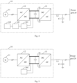
- Fig. 1 is a schematic diagram of a grid-forming wind turbine provided in an embodiment of the present disclosure.
- the grid-forming wind turbine 10 includes a generator 11, a generator-side converter (AC/DC) 12, a grid-side converter (DC/AC) 13, and an energy storage device 14.
- the grid-forming wind turbine 10 may be electrically connected to a power grid 20.
- the generator-side converter 12 is electrically connected to the generator 11.
- the grid-side converter 13 is electrically connected to the generator-side converter 12 through a direct-current(DC) bus 15.
- the energy storage device 14 is connected to the direct-current bus 15, and the energy storage device 14 can be charged or discharged.
- the grid-side converter 13 may be configured to be electrically connected to the power grid 20.
- Inductors, capacitors, and resistors and other structures may be installed between the grid-side converter 13 and the power grid 20. For example, as shown in Fig. 1 , an inductor L1 and a capacitor C1 or other structures may be provided between the grid-side converter 13 and the power grid 20, which will not be listed one by one here.
- the cut-off frequency of the active power control closed-loop is a cut-off frequency of a transfer function of the active power control closed-loop, also known as a bandwidth frequency.
- the cut-off frequency of the reactive power control closed-loop is a cut-off frequency of a transfer function of the reactive power control closed-loop, also known as a bandwidth frequency.
- the bandwidth frequency refers to a frequency at which the amplitude-frequency characteristic of the closed-loop is controlled to decrease to -3 decibels (dB). The higher the cut-off frequency, the faster the dynamic change of the system, and the poorer the anti-interference performance.
- the power switch module includes a plurality of power switch devices, which can be turned on or off under the control of the pulse width modulation signal generated by the control module, so that a change value of output internal potential voltage of the grid-side converter 13 within a cut-off period is less than a stable change threshold.
- the energy storage device 14 is passively discharged to provide active output for the power grid 20.
- the cut-off frequency of the frequency reduced active power control closed-loop and the cut-off frequency of the frequency reduced reactive power control closed-loop are less than or equal to a first preset value.
- the duration of the cut-off period increases.
- the frequency of the power grid 20 attenuates, the voltage difference between the grid-forming wind turbine 10 and the power grid 20 increases.
- the energy storage device 14 is passively discharged to provide active output for the power grid 20, thereby providing frequency and inertia support for the power grid 20 and improving the stability of a wind power generation system including the wind turbine.
- the energy storage device 14 provides active output to the power grid 20 passively, instruction control is not required, the time for instruction control can be saved, and the speed of providing frequency and inertia support to the power grid 20 can be improved.
- a fifth processing result obtained by the integral processing, a sixth processing result obtained by the proportional processing, and a seventh processing result obtained by the derivative processing are added to obtain a third sum, which is a per-unit value.
- the third sum is added to a per-unit value 1 of a feed-forward signal to obtain a fourth sum, and the fourth sum is multiplied by an amplitude conversion value Ubase to obtain a control amplitude Uvsg.
- the second aspect of the present disclosure provides a control method for a grid-forming wind turbine.
- the method may be executed by the grid-side converter in the grid-forming wind turbine in the above embodiments. Further, the method may be executed by the control module of the grid-side converter in the grid-forming wind turbine in the above embodiments.
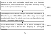
- Fig. 6 is a flowchart of a control method for a grid-forming wind turbine provided in an embodiment of the present disclosure. As shown in Fig. 6 , the control method for the grid-forming wind turbine may include steps S301 to S303.
- a cut-off frequency of the frequency reduced active power control closed-loop and a cut-off frequency of the frequency reduced reactive power control closed-loop are less than or equal to a first preset value.
- the stable change threshold is a change value threshold used for representing and determining whether the output internal potential voltage is stable.
- the active power control closed-loop includes a first proportional integral derivative control unit and a low-pass filter
- the reactive power control closed-loop includes a second proportional integral derivative control unit.
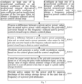
- Fig. 7 is a flowchart of a control method for a grid-forming wind turbine provided in another embodiment of the present disclosure. Fig. 7 differs from Fig. 6 in that the control method for the grid-forming wind turbine shown in Fig. 7 further includes steps S304 and S305, and step S301 in Fig. 6 can be specifically refined into steps S3011 to S3013 in Fig. 7 .
- a desired cut-off frequency of the frequency reduced active power control closed-loop i.e., the target cut-off frequency
- an appropriate proportional coefficient and integral coefficient of the first proportional integral derivative control unit can be calculated based on the target cut-off frequency and a transfer function of an active power control closed-loop, and the appropriate proportional coefficient and integral coefficient of the first proportional integral derivative control unit can be configured in the first proportional integral derivative control unit.
- the transfer function of the active power control closed-loop can be determined based on a specific architecture of the active power control closed-loop, and is not limited here.
- the transfer function of the active power control closed-loop can be expressed as follows (1) to (5):
- C dc represents a capacitance value of the direct-current bus
- u dc 0 and U dc base represent steady-state direct-current bus voltage and direct-current voltage reference value respectively
- K T represents a proportional coefficient
- K I represents an integral coefficient
- K E represents a derivative coefficient
- ⁇ base represents an internal potential angular frequency reference value of the power grid
- K x represents a coefficient between a phase angle difference and a power increment
- U represents an amplitude of alternating-current voltage
- X L represents an impedance.
- an appropriate gain coefficient and inertia time constant can be obtained based on a rotor motion equation of the generator of the grid-forming wind turbine, and the appropriate gain coefficient and inertia time constant can be configured in the low-pass filter.
- a rotational inertia of the generator and a damping coefficient of the generator in the rotor motion equation of the generator are obtained;
- a target gain coefficient and a target inertia time constant are obtained based on the rotational inertia of the generator and the damping coefficient of the generator;
- the target gain coefficient and the target inertia time constant are configured as the gain coefficient and inertia time constant of the low-pass filter respectively.
- the target gain coefficient includes a gain coefficient that enables the cut-off frequency of the active power control closed-loop to reach the target cut-off frequency.
- the target inertia time constant includes an inertia time constant that enables the cut-off frequency of the active power control closed-loop to reach the target cut-off frequency.
- J represents the rotational inertia of the generator
- T m represents a mechanical torque of the generator
- T e represents an electromagnetic torque of the generator
- D represents the damping coefficient of the generator
- ⁇ represents an angular frequency of a generator rotor
- ⁇ g represents a rated angular frequency of the power grid.
- the first target proportional coefficient can be configured as the proportional coefficient of the first proportional integral derivative control unit, so that the cut-off frequency of the frequency reduced active power control closed-loop is less than or equal to the first preset value; or the first target integral coefficient can be configured as the integral coefficient of the first proportional integral derivative control unit, so that the cut-off frequency of the frequency reduced active power control closed-loop is less than or equal to the first preset value; or the target gain coefficient and the target inertia time constant can be configured as the gain coefficient and inertia time constant of the low-pass filter respectively, so that the cut-off frequency of the frequency reduced active power control closed-loop is less than or equal to the first preset value.
- the communication interface 403 is mainly configured to implement communication between various modules, apparatuses, units, and/or devices in the embodiments of the present disclosure. Input and/or output devices can also be connected by the communication interface 403.
- Embodiments of the present disclosure further provide a computer-readable storage medium, storing computer program instructions that, when executed by a processor, can implement the method for controlling a grid-forming wind turbine in the above embodiments and achieve the same technical effects, which will not be repeated here in order to avoid repetition.
- the computer-readable storage medium may be a non-transient computer-readable storage medium, such as a read-only memory (ROM), a random access memory (RAM), a magnetic disk, or an optical disk.
- Such a processor may be, but is not limited to a general-purpose processor, a dedicated processor, a special disclosure processor, or a field programmable logic circuit. It can also be understood that each box in the block view and/or flowchart and a combination of boxes in the block view and/or flowchart can be implemented by dedicated hardware that executes specified functions or actions, or by a combination of dedicated hardware and computer instructions.
Landscapes
- Engineering & Computer Science (AREA)
- Power Engineering (AREA)
- Control Of Eletrric Generators (AREA)
- Wind Motors (AREA)
- Supply And Distribution Of Alternating Current (AREA)
Abstract
Description
- The present disclosure claims priority to
Chinese Patent Disclosure No. 202211319731.3, entitled "GRID-FORMING WIND TURBINE CONTROL METHOD THEREFOR, AND CONTROLLER" filed on October 26, 2022 - The present disclosure belongs to the field of wind power generation, and in particular, relates to a grid-forming wind turbine, a control method therefor, and a controller.
- A wind turbine is an apparatus that can convert wind energy into electrical energy. The electrical energy generated by the wind turbine can be transmitted to a power grid through a transmission network for distribution and use. The speed and active output of the wind turbine can be adjusted based on changes in wind speed to output electrical energy. However, in the case that frequency attenuation occurs in the power grid, the wind turbine cannot provide inertia and frequency support for the power grid, resulting in poor stability of a wind power generation system including the wind turbine.
- Embodiments of the present disclosure provide a grid-forming wind turbine and a control method therefor, and a controller, which can improve the stability of a wind power generation system including the wind turbine.
- In the first aspect, embodiments of the present disclosure provide a grid-forming wind turbine, including: a generator; a generator-side converter electrically connected to the generator; a grid-side converter electrically connected to the generator-side converter by a direct-current bus; and an energy storage device connected to the direct-current bus for charging or discharging. The grid-side converter includes: a control module, configured to generate a pulse width modulation signal based on a frequency reduced active power control closed-loop and a frequency reduced reactive power control closed-loop, where a cut-off frequency of the frequency reduced active power control closed-loop and a cut-off frequency of the frequency reduced reactive power control closed-loop are less than or equal to a first preset value; and a power switch module, including multiple power switch devices, which are turned on or off under the control of the pulse width modulation signal, so that a change value of output internal potential voltage of the grid-side converter within a cut-off period is less than or equal to a preset stable change threshold. In the case that a frequency of a power grid attenuates, the energy storage device is passively discharged to provide active output for the power grid. The power grid is electrically connected to the grid-forming wind turbine, and the stable change threshold is a change value threshold used for representing and determining whether the output internal potential voltage is stable.
- In the second aspect, embodiments of the present disclosure provide a control method for a grid-forming wind turbine, applied to the grid-side converter in the grid-forming wind turbine in the first aspect, the grid-forming wind turbine being configured to be electrically connected to a power grid, the control method including: generating a pulse width modulation signal based on a frequency reduced active power control closed-loop and a frequency reduced reactive power control closed-loop, where a cut-off frequency of the frequency reduced active power control closed-loop and a cut-off frequency of the frequency reduced reactive power control closed-loop are less than or equal to a first preset value; controlling the power switch devices in the grid-side converter to be turned on or off based on the pulse width modulation signal, so that a change value of output internal potential voltage of the grid-side converter within a cut-off period is less than or equal to a preset stable change threshold, where the stable change threshold is a change value threshold used for representing and determining whether the output internal potential voltage is stable; and providing active output for the power grid by passive discharge of the energy storage device in the case that a frequency of the power grid attenuates.
- In the third aspect, embodiments of the present disclosure provide a controller for a grid-side converter, including: a processor and a memory storing computer program instructions, where when the processor executes the computer program instructions, the control method for the wind turbine in the second aspect is implemented.
- Embodiments of the present disclosure provide a grid-forming wind turbine and a control method therefor, and a controller. The grid-forming wind turbine includes a generator, a generator-side converter, a grid-side converter, and an energy storage device. The grid-side converter includes a control module and a power switch module, and the power switch module includes multiple power switch devices. The control module can generate a pulse width modulation signal based on a frequency reduced active power control closed-loop and a frequency reduced reactive power control closed-loop. The pulse width modulation signal can control the power switch devices to be switched on or off, so that a change value of output internal potential voltage of the grid-side converter within a cut-off period is less than or equal to a stable change threshold, that is, the output internal potential voltage of the grid-side converter can remain stable in the cut-off period. The cut-off frequency of the frequency reduced active power control closed-loop and the cut-off frequency of the frequency reduced reactive power control closed-loop are less than or equal to a first preset value. Correspondingly, the duration of the cut-off period increases. In the case that the frequency of a power grid attenuates, the voltage difference between the grid-forming wind turbine and the power grid increases. Due to the physical characteristics of structures between the grid-forming wind turbine and the power grid, the energy storage device is passively discharged to provide active output for the power grid, thereby providing frequency and inertia support for the power grid and improving the stability of a wind power generation system including the wind turbine.
- In order to explain the technical solutions of the embodiments of the present disclosure more clearly, the accompanying drawings required for use in the embodiments of the present disclosure will be briefly introduced below. Those of ordinary skill in the art can derive other drawings based on the accompanying drawings without any creative effort.
-
Fig. 1 is a schematic diagram of a grid-forming wind turbine provided in an embodiment of the present disclosure; -
Fig. 2 is a logical schematic diagram of an example of an active power control closed-loop provided in an embodiment of the present disclosure; -
Fig. 3 is a logical schematic diagram of an example of a reactive power control closed-loop provided in an embodiment of the present disclosure; -
Fig. 4 is a schematic diagram of a grid-forming wind turbine provided in another embodiment of the present disclosure; -
Fig. 5 is a schematic diagram of a grid-forming wind turbine provided in still another embodiment of the present disclosure; -
Fig. 6 is a flowchart of a control method for a grid-forming wind turbine provided in an embodiment of the present disclosure; -
Fig. 7 is a flowchart of a control method for a grid-forming wind turbine provided in another embodiment of the present disclosure; and -
Fig. 8 is a schematic diagram of a controller for a grid-side converter provided in an embodiment of the present disclosure. - Features and exemplary embodiments of various aspects of the present disclosure will be described in detail below. In order to make the objectives, technical solutions, and advantages of the present disclosure clearer, the present disclosure will be further described in detail below with reference to the accompanying drawings and specific embodiments. It should be understood that the specific embodiments described here are only intended to explain the present disclosure, but not to limit the present disclosure. For those skilled in the art, the present disclosure can be implemented without some of these specific details. The following descriptions of the embodiments are merely to provide a better understanding of the present invention by showing examples of the present invention.
- A wind turbine is an apparatus that can convert wind energy into electrical energy. The electrical energy generated by the wind turbine can be transmitted to a power grid through a transmission network for distribution and use by the power grid. The speed and active output of the wind turbine can be adjusted according to changes in wind speed to output electrical energy. However, in the case that frequency attenuation occurs in the power grid, wind turbine cannot provide inertia and frequency support for the power grid, resulting in poor stability of a wind power generation system including the wind turbine.
- Embodiments of the present disclosure provide a grid-forming wind turbine and a control method therefor, and a controller. The grid-forming wind turbine has self-synchronous grid characteristics and can exhibit voltage source control characteristics to the outside. In an off-grid scenario, the grid-forming wind turbine can serve as a voltage source to supply power to some electrical devices. In a grid-connected scenario, the grid-forming wind turbine can provide inertia and frequency support for a power grid connected to the wind turbine. In the embodiments of the present disclosure, a pulse width modulation signal for controlling power switch devices in a grid-side converter is generated based on a frequency reduced active power control closed-loop and a frequency reduced reactive power control closed-loop, so that the fluctuation of the output internal potential voltage of the grid-side converter is minimized. In the case that the frequency of the power grid attenuates, the difference between the output internal potential voltage of the grid-side converter and the voltage of the power grid increases. According to the physical characteristics of connection structures between the grid-forming wind turbine and the power grid, the grid-forming wind turbine will provide active output for the power grid by its energy storage device, to provide inertia and frequency support for the power grid, thereby improving the stability of a wind power generation system including the wind turbine.
- The following introduces the grid-forming wind turbine and the control method therefor, and the controller provided in the present disclosure, respectively.
- The first aspect of the present disclosure provides a grid-forming wind turbine.
Fig. 1 is a schematic diagram of a grid-forming wind turbine provided in an embodiment of the present disclosure. As shown inFig. 1 , the grid-formingwind turbine 10 includes agenerator 11, a generator-side converter (AC/DC) 12, a grid-side converter (DC/AC) 13, and anenergy storage device 14. The grid-formingwind turbine 10 may be electrically connected to apower grid 20. - The generator-
side converter 12 is electrically connected to thegenerator 11. The grid-side converter 13 is electrically connected to the generator-side converter 12 through a direct-current(DC)bus 15. Theenergy storage device 14 is connected to the direct-current bus 15, and theenergy storage device 14 can be charged or discharged. The grid-side converter 13 may be configured to be electrically connected to thepower grid 20. Inductors, capacitors, and resistors and other structures may be installed between the grid-side converter 13 and thepower grid 20. For example, as shown inFig. 1 , an inductor L1 and a capacitor C1 or other structures may be provided between the grid-side converter 13 and thepower grid 20, which will not be listed one by one here. - The generator-
side converter 12 can convert electrical energy generated by thegenerator 11 into direct-current electrical energy and transmit the direct-current electrical energy to the grid-side converter 13 through the direct-current bus 15, and then the grid-side converter 13 converts the transmitted direct-current electrical energy into alternating-current electrical energy and transmits the alternating-current electrical energy to the outside. In some cases, the DC power converted and transmitted by the generator-side converter 12 to the direct-current bus 15 can charge theenergy storage device 14. In some cases, theenergy storage device 14 can be discharged, the electrical energy released by theenergy storage device 14 can be transmitted to the grid-side converter 13 through the direct-current bus 15, converted by the grid-side converter 13 and then provided to thepower grid 20, and the electrical energy released by theenergy storage device 14 can be used as active output. - The grid-
side converter 13 may include a control module and a power switch module. - The control module may be configured to generate a pulse width modulation signal based on a frequency reduced active power control closed-loop and a frequency reduced reactive power control closed-loop. A control phase required for modulating the pulse width modulation signal can be obtained based on the frequency reduced active power control closed-loop, and a control amplitude required for modulating the pulse width modulation signal can be obtained based on the frequency reduced reactive power control closed-loop. The frequency reduced here refers to reduction of a cut-off frequency of the active power control closed-loop and reduction of a cut-off frequency of the reactive power control closed-loop. The cut-off frequency of the active power control closed-loop is a cut-off frequency of a transfer function of the active power control closed-loop, also known as a bandwidth frequency. Similarly, the cut-off frequency of the reactive power control closed-loop is a cut-off frequency of a transfer function of the reactive power control closed-loop, also known as a bandwidth frequency. The bandwidth frequency refers to a frequency at which the amplitude-frequency characteristic of the closed-loop is controlled to decrease to -3 decibels (dB). The higher the cut-off frequency, the faster the dynamic change of the system, and the poorer the anti-interference performance. In the embodiments of the present disclosure, the cut-off frequency of the frequency reduced active power control closed-loop and the cut-off frequency of the frequency reduced reactive power control closed-loop are less than or equal to a first preset value, such as 10 hertz. In order to further improve the stability of a wind power generation system including the wind turbine, the cut-off frequency of the frequency reduced active power control closed-loop and the cut-off frequency of the frequency reduced reactive power control closed-loop may be less than or equal to a second preset value, such as 5 Hz.
- The power switch module includes a plurality of power switch devices, which can be turned on or off under the control of the pulse width modulation signal generated by the control module, so that a change value of output internal potential voltage of the grid-
side converter 13 within a cut-off period is less than a stable change threshold. In the case that the frequency of thepower grid 20 attenuates, theenergy storage device 14 is passively discharged to provide active output for thepower grid 20. - The cut-off period is negatively correlated with the cut-off frequency of the active power control closed-loop and the cut-off frequency of the reactive power control closed-loop. The lower the cut-off frequencies, the longer the cut-off period. The grid-
side converter 13 responds once every cut-off period to adjust its output internal potential voltage. The change value of the output internal potential voltage of the grid-side converter 13 in the same cut-off period is very small and relatively stable, that is, the change value of the output internal potential voltage of the grid-side converter 13 in the same cut-off period is less than or equal to the preset stable change threshold. The change value of the output internal potential voltage of the grid-side converter 13 is an absolute value of a change of the output internal potential voltage of the grid-side converter 13. The stable change threshold is a change value threshold for determining whether the output internal potential voltage is stable. If the change value of the output internal potential voltage of the grid-side converter 13 in the same cut-off period is less than or equal to the stable change threshold, it indicates that the output internal potential voltage of the grid-side converter 13 during the cut-off period remains stable. If the change value of the output internal potential voltage of the grid-side converter 13 in the same cut-off period is greater than the stable change threshold, it indicates that the output internal potential voltage of the grid-side converter 13 during the cut-off period does not remain stable. The stable change threshold can be set according to the scenario, demand, experience, etc., which is not limited here. For example, the stable change threshold may be 0.01 per unit (p.u). - If both the cut-off frequency of the active power control closed-loop and the cut-off frequency of the reactive power control closed-loop decrease, the corresponding cut-off period increases, that is, the dynamic change of the system slows down and the anti-interference performance increases. Within the same cut-off period, even if the frequency of the
power grid 20 attenuates, the output internal potential voltage of the grid-side converter 13 remains stable, and the voltage difference between the grid-side converter 13 and thepower grid 20 increases. In the presence of an inductor, a capacitor, a resistor, etc. between the grid-side converter 13 and thepower grid 20, due to the characteristics of inductive elements, in the case that the voltage difference between the grid-side converter 13 and thepower grid 20 increases, the grid-formingwind turbine 10 will passively provide active output for thepower grid 20. The active output provided for thepower grid 20 by the grid-formingwind turbine 10 includes active output provided for thepower grid 20 by passive discharge of theenergy storage device 14. Here, the active output is referred to as active power. - In the case that the frequency of the
power grid 20 does not attenuate and the electrical energy generated by thegenerator 11 is sufficient, theenergy storage device 14 can obtain the electricity by the direct-current bus 15, i.e., achieve charging, and the stored electricity can be discharged when needed. - In the embodiments of the present disclosure, the grid-forming wind turbine includes a
generator 11, a generator-side converter 12, a grid-side converter 13, and anenergy storage device 14. The grid-side converter 13 includes a control module and a power switch module, and the power switch module includes multiple power switch devices. The control module can generate a pulse width modulation signal based on a frequency reduced active power control closed-loop and a frequency reduced reactive power control closed-loop. The pulse width modulation signal can control the power switch devices to be turned on or off, so that a change value of output internal potential voltage of the grid-side converter 13 in a cut-off period is less than or equal to a stable change threshold, that is, the output internal potential voltage of the grid-side converter 13 can remain stable in the cut-off period. The cut-off frequency of the frequency reduced active power control closed-loop and the cut-off frequency of the frequency reduced reactive power control closed-loop are less than or equal to a first preset value. Correspondingly, the duration of the cut-off period increases. In the case that the frequency of thepower grid 20 attenuates, the voltage difference between the grid-formingwind turbine 10 and thepower grid 20 increases. Due to the physical characteristics of structures between the grid-formingwind turbine 10 and thepower grid 20, theenergy storage device 14 is passively discharged to provide active output for thepower grid 20, thereby providing frequency and inertia support for thepower grid 20 and improving the stability of a wind power generation system including the wind turbine. Moreover, because theenergy storage device 14 provides active output to thepower grid 20 passively, instruction control is not required, the time for instruction control can be saved, and the speed of providing frequency and inertia support to thepower grid 20 can be improved. - In some embodiments, the above control module may include a processing unit and a modulation unit.
- The processing unit may be configured to process a difference between a given active power value and an actual active power value output by the grid-
side converter 13 based on the frequency reduced active power control closed-loop to obtain a control phase, and process a difference between a given reactive power parameter value and an actual reactive power parameter value output by the grid-side converter 13 based on the frequency reduced reactive power control closed-loop to obtain a control amplitude. - The active power control closed-loop controls active power based on the given value of the active power and the measured actual value of the active power output by the grid-
side converter 13. The active power control closed-loop can process the difference between the given value of the active power and the actual value of the active power to obtain the control phase. The reactive power control closed-loop controls reactive power based on the given value of the reactive power and the actual value of the reactive power parameter output by the grid-side converter 13. The reactive power control closed-loop can process the difference between the given value of the reactive power and the actual value of the reactive power to obtain the control amplitude. - In some examples, the active power control closed-loop may include a first proportional integral derivative (PID) control unit and a low-pass filter. The low-pass filter may include a first-order low-pass filter or a second-order low-pass filter.
Fig. 2 is a logical schematic diagram of an example of an active power control closed-loop provided in an embodiment of the present disclosure. As shown inFig. 2 , the difference ΔP between the given value of the active power and the actual value of the active power can be input into the first proportional integral derivative control unit for proportional integral derivative processing. InFig. 2 , KEs represents integral processing, involving an integral coefficient KE; KT represents proportional processing, involving a proportional coefficient KT; and KI/s represents derivative processing, involving a derivative coefficient KI. A first processing result obtained by the integral processing, a second processing result obtained by the proportional processing, and a third processing result obtained by the derivative processing are added to obtain a first sum, and the first sum is input into the low-pass filter for low-pass filtering. InFig. 2, 1 /(KJs+KD) represents low-pass filtering, involving parameters KJ and KD. A fourth processing result output by the low-pass filter is a per-unit value. The fourth processing result is added to a per-unit value 1 of a feed-forward signal to obtain a second sum, and the second sum is multiplied by an angular frequency conversion value ω base to obtain an angular frequency ωvsg, where the angular frequency ωvsg is a nominal value. The derivative processing is performed on the angular frequency ωvsg to obtain a control phase θvsg, where 1/s inFig. 2 represents the derivative processing. - The reactive power control closed-loop may include a second proportional integral derivative control unit.
Fig. 3 is a logical schematic diagram of an example of a reactive power control closed-loop provided in an embodiment of the present disclosure. As shown inFig. 3 , the difference ΔQ between the given value of the reactive power and the actual value of the reactive power can be input into the second proportional integral derivative control unit for proportional integral derivative processing. InFig. 3 , KEs represents integral processing, involving an integral coefficient KE; KT represents proportional processing, involving a proportional coefficient KT; and KI/s represents derivative processing, involving a derivative coefficient KI. A fifth processing result obtained by the integral processing, a sixth processing result obtained by the proportional processing, and a seventh processing result obtained by the derivative processing are added to obtain a third sum, which is a per-unit value. The third sum is added to a per-unit value 1 of a feed-forward signal to obtain a fourth sum, and the fourth sum is multiplied by an amplitude conversion value Ubase to obtain a control amplitude Uvsg. - In the embodiments of the present disclosure, the cut-off frequency of the active power control closed-loop can be reduced by configuring the proportional coefficient of the first proportional integral derivative control unit, the integral coefficient of the first proportional integral derivative control unit, a gain coefficient of the low-pass filter, and an inertia time constant of the low-pass filter. Specifically, at least one of the proportional coefficient or the integral coefficient configured for the first proportional integral derivative control unit, and/or the gain coefficient and the inertia time constant configured for the low-pass filter, make the cut-off frequency of the frequency reduced active power control closed-loop less than or equal to the first preset value.
- The cut-off frequency of the reactive power control closed-loop can be reduced by configuring the proportional coefficient of the second proportional integral derivative control unit and the integral coefficient of the second proportional integral derivative control unit. Specifically, at least one of the proportional coefficient or the integral coefficient configured for the second proportional integral derivative control unit makes the cut-off frequency of the frequency reduced reactive power control closed-loop less than or equal to the first preset value.
- Specific configuration methods for the proportional coefficient of the first proportional integral derivative control unit, the integral coefficient of the first proportional integral derivative control unit, the gain coefficient of the low-pass filter, the inertia time constant of the low-pass filter, the proportional coefficient of the second proportional integral derivative control unit, and the integral coefficient of the second proportional integral derivative control unit will be explained in detail below.
- In some embodiments, the
energy storage device 14 in the above embodiments may be implemented as a flywheel device.Fig. 4 is a schematic diagram of a grid-forming wind turbine provided in another embodiment of the present disclosure.Fig. 4 differs fromFig. 1 in that theenergy storage device 14 shown inFig. 4 may include anelectrical energy converter 141, anelectric motor 142, and aflywheel 143. - In the case that the frequency of the
power grid 20 does not attenuate and the electrical energy generated by thegenerator 11 is sufficient, theelectrical energy converter 141 can convert the electrical energy of the direct-current bus 15 into electrical energy that meets the requirements of theelectric motor 142, and theelectric motor 142 is driven by the electrical energy converted by theelectrical energy converter 141, to drive theflywheel 143 to rotate, that is, the electrical energy is converted into mechanical energy for storage. - In the case that the frequency of the
power grid 20 attenuates, theflywheel 143 rotates to drive theelectric motor 142 to generate electrical energy, and theelectrical energy converter 141 converts the electrical energy generated by theelectric motor 142 into electrical energy that meets the requirements of the direct-current bus 15, that is, the mechanical energy is converted into electrical energy for release, to provide frequency and inertia support for thepower grid 20. - In some embodiments, the
energy storage device 14 may be implemented as a battery module.Fig. 5 is a schematic diagram of a grid-forming wind turbine provided in still another embodiment of the present disclosure.Fig. 5 differs fromFig. 1 in that theenergy storage device 14 shown inFig. 5 may include abattery module 144. Thebattery module 144 may include at least one battery, which is not limited here. In the case that thebattery module 144 includes two or more batteries, the connection method of the batteries in thebattery module 144 is not limited. In the case that theenergy storage device 14 includes thebattery module 144, a special electrical energy converter is not required between thebattery module 144 and the direct-current bus, which can further simplify the structure of the grid-forming wind turbine. - In the case that the frequency of the
power grid 20 does not attenuate and the electrical energy generated by thegenerator 11 is sufficient, the direct-current bus 15 can charge thebattery module 144. - In the case that the frequency of the
power grid 20 attenuates, thebattery module 144 can release electrical energy to provide frequency and inertia support for thepower grid 20. - A control method for the grid-forming wind turbine in the above embodiments will be explained below. The second aspect of the present disclosure provides a control method for a grid-forming wind turbine. The method may be executed by the grid-side converter in the grid-forming wind turbine in the above embodiments. Further, the method may be executed by the control module of the grid-side converter in the grid-forming wind turbine in the above embodiments.
Fig. 6 is a flowchart of a control method for a grid-forming wind turbine provided in an embodiment of the present disclosure. As shown inFig. 6 , the control method for the grid-forming wind turbine may include steps S301 to S303. - In step S301, a pulse width modulation signal is generated based on a frequency reduced active power control closed-loop and a frequency reduced reactive power control closed-loop.
- A cut-off frequency of the frequency reduced active power control closed-loop and a cut-off frequency of the frequency reduced reactive power control closed-loop are less than or equal to a first preset value.
- In some examples, the cut-off frequency of the frequency reduced active power control closed-loop and the cut-off frequency of the frequency reduced reactive power control closed-loop are less than or equal to a second preset value.
- In step S302, the power switch devices in the grid-side converter is controlled to be turned on or off based on the pulse width modulation signal, so that a change value of output internal potential voltage of the grid-side converter in a cut-off period is less than or equal to a preset stable change threshold.
- The stable change threshold is a change value threshold used for representing and determining whether the output internal potential voltage is stable.
- In step S303, active output is provided for the power grid by passive discharge of the energy storage device in the case that a frequency of a power grid attenuates.
- The specific content of steps S301 to S303 can be referred to the relevant explanations in the above embodiments, and will not be repeated here.
- In some embodiments, the active power control closed-loop includes a first proportional integral derivative control unit and a low-pass filter, and the reactive power control closed-loop includes a second proportional integral derivative control unit.
Fig. 7 is a flowchart of a control method for a grid-forming wind turbine provided in another embodiment of the present disclosure.Fig. 7 differs fromFig. 6 in that the control method for the grid-forming wind turbine shown inFig. 7 further includes steps S304 and S305, and step S301 inFig. 6 can be specifically refined into steps S3011 to S3013 inFig. 7 . - In step S304, at least one of a proportional coefficient or an integral coefficient of the first proportional integral derivative control unit, and/or, a gain coefficient and an inertia time constant of the low-pass filter is configured, to obtain a frequency reduced active power control closed-loop.
- For the configuration of the first proportional integral derivative control unit, a desired cut-off frequency of the frequency reduced active power control closed-loop, i.e., the target cut-off frequency, can be first obtained, an appropriate proportional coefficient and integral coefficient of the first proportional integral derivative control unit can be calculated based on the target cut-off frequency and a transfer function of an active power control closed-loop, and the appropriate proportional coefficient and integral coefficient of the first proportional integral derivative control unit can be configured in the first proportional integral derivative control unit. Specifically, the target cut-off frequency is obtained, and at least one of a first target proportional coefficient or a first target integral coefficient corresponding to the target cut-off frequency is calculated based on a corresponding relationship between the proportional coefficient and integral coefficient in the transfer function of the active power control closed-loop and the cut-off frequency of the active power control closed-loop; the first target proportional coefficient is configured as the proportional coefficient of the first proportional integral derivative control unit, and/or, the first target integral coefficient is configured as the integral coefficient of the first proportional integral derivative control unit. The target cut-off frequency is less than or equal to the first preset value. The first target proportional coefficient includes a proportional coefficient that enables the cut-off frequency of the active power control closed-loop to reach the target cut-off frequency. The first target integral coefficient includes an integral coefficient that enables the cut-off frequency of the active power control closed-loop to reach the target cut-off frequency.
- The transfer function of the active power control closed-loop can be determined based on a specific architecture of the active power control closed-loop, and is not limited here. For example, the transfer function of the active power control closed-loop can be expressed as follows (1) to (5):




- Here, Cdc represents a capacitance value of the direct-current bus; u dc0 and Udc
base represent steady-state direct-current bus voltage and direct-current voltage reference value respectively; KT represents a proportional coefficient; KI represents an integral coefficient; KE represents a derivative coefficient; ωbase represents an internal potential angular frequency reference value of the power grid; Kx represents a coefficient between a phase angle difference and a power increment; U represents an amplitude of alternating-current voltage; XL represents an impedance. - For the configuration of the low-pass filter, an appropriate gain coefficient and inertia time constant can be obtained based on a rotor motion equation of the generator of the grid-forming wind turbine, and the appropriate gain coefficient and inertia time constant can be configured in the low-pass filter. Specifically, a rotational inertia of the generator and a damping coefficient of the generator in the rotor motion equation of the generator are obtained; a target gain coefficient and a target inertia time constant are obtained based on the rotational inertia of the generator and the damping coefficient of the generator; the target gain coefficient and the target inertia time constant are configured as the gain coefficient and inertia time constant of the low-pass filter respectively. The target gain coefficient includes a gain coefficient that enables the cut-off frequency of the active power control closed-loop to reach the target cut-off frequency. The target inertia time constant includes an inertia time constant that enables the cut-off frequency of the active power control closed-loop to reach the target cut-off frequency.
- The rotor motion equation can be expressed as equation (6) below:

- Here, J represents the rotational inertia of the generator; Tm represents a mechanical torque of the generator; Te represents an electromagnetic torque of the generator; D represents the damping coefficient of the generator; ω represents an angular frequency of a generator rotor; and ωg represents a rated angular frequency of the power grid. It should be noted that the value of each parameter in equation (6) is a per-unit value.
- In some examples, the first target proportional coefficient can be configured as the proportional coefficient of the first proportional integral derivative control unit, so that the cut-off frequency of the frequency reduced active power control closed-loop is less than or equal to the first preset value; or the first target integral coefficient can be configured as the integral coefficient of the first proportional integral derivative control unit, so that the cut-off frequency of the frequency reduced active power control closed-loop is less than or equal to the first preset value; or the target gain coefficient and the target inertia time constant can be configured as the gain coefficient and inertia time constant of the low-pass filter respectively, so that the cut-off frequency of the frequency reduced active power control closed-loop is less than or equal to the first preset value.
- In other examples, the first target proportional coefficient and the first target integral coefficient can be configured as the proportional coefficient and integral coefficient of the first proportional integral derivative control unit respectively, so that the cut-off frequency of the frequency reduced active power control closed-loop is less than or equal to the first preset value; or the first target proportional coefficient, the target gain coefficient, and the target inertia time constant can be configured as the proportional coefficient of the first proportional integral derivative control unit and the gain coefficient and inertia time constant of the low-pass filter respectively, so that the cut-off frequency of the frequency reduced active power control closed-loop is less than or equal to the first preset value; or the first target integral coefficient, the target gain coefficient, and the target inertia time constant can be configured as the integral coefficient of the first proportional integral derivative control unit and the gain coefficient and inertia time constant of the low-pass filter respectively, so that the cut-off frequency of the frequency reduced active power control closed-loop is less than or equal to the first preset value; or the first target proportional coefficient, the first target integral coefficient, the target gain coefficient, and the target inertia time constant can be configured as the proportional coefficient and integral coefficient of the first proportional integral derivative control unit and the gain coefficient and inertia time constant of the low-pass filter respectively, so that the cut-off frequency of the frequency reduced active power control closed-loop is less than or equal to the first preset value.
- In step S305, at least one of a proportional coefficient or an integral coefficient of the second proportional integral derivative control unit is configured to obtain a frequency reduced reactive power control closed-loop.
- For the configuration of the second proportional integral derivative control unit, a desired cut-off frequency of the frequency reduced reactive power control closed-loop, namely, a target cut-off frequency, can be first obtained, an appropriate proportional coefficient and integral coefficient of the second proportional integral derivative control unit can be calculated based on the target cut-off frequency and a transfer function of a reactive power control closed-loop, and the appropriate proportional coefficient and integral coefficient of the second proportional integral derivative control unit can be configured in the second proportional integral derivative control unit. Specifically, the target cut-off frequency is obtained, and at least one of a second target proportional coefficient or a second target integral coefficient corresponding to the target cut-off frequency is calculated based on a corresponding relationship between the proportional coefficient and integral coefficient in the transfer function of the reactive power control closed-loop and the cut-off frequency of the reactive power control closed-loop; the second target proportional coefficient is configured as the proportional coefficient of the second proportional integral derivative control unit, and/or the second target integral coefficient is configured as the integral coefficient of the second proportional integral derivative control unit. The second target proportional coefficient includes a proportional coefficient that enables the cut-off frequency of the reactive power control closed loop to reach the target cut-off frequency. The second target integral coefficient includes an integral coefficient that enables the cut-off frequency of the reactive power control closed-loop to reach the target cut-off frequency.
- The transfer function of the reactive power control closed-loop can be determined based on a specific architecture of the reactive power control closed-loop, and is not limited here.
- In some examples, the second target proportional coefficient can be configured as the proportional coefficient of the second proportional integral derivative control unit, so that the cut-off frequency of the frequency reduced reactive power control closed-loop is less than or equal to the first preset value; or the second target integral coefficient can be configured as the integral coefficient of the second proportional integral derivative control unit, so that the cut-off frequency of the frequency reduced reactive power control closed-loop is less than or equal to the first preset value; or the second target proportional coefficient and the second target integral coefficient can be configured as the proportional coefficient and integral coefficient of the second proportional integral derivative control unit respectively, so that the cut-off frequency of the frequency reduced reactive power control closed-loop is less than or equal to the first preset value.
- In step S3011, a difference between a given active power value and an actual active power value output by the grid-side converter is processed based on the frequency reduced active power control closed-loop to obtain a control phase.
- In step S3012, a difference between a given reactive power parameter value and an actual reactive power parameter value output by the grid-side converter is processed using the frequency reduced reactive power control closed loop to obtain a control amplitude.
- In step S3013, a pulse width modulation signal is modulated and generated based on the control phase and the control amplitude.
- The specific content of steps S3011 to S3013 can be referred to the relevant explanations in the above embodiments, and will not be repeated here.
- The third aspect of the present disclosure further provides a controller for a grid-side converter.
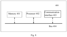
Fig. 8 is a schematic diagram of a controller for a grid-side converter provided in an embodiment of the present disclosure. As shown inFig. 8 , thecontroller 400 for a grid-side converter includes amemory 401, aprocessor 402, and a computer program stored in thememory 401 and executable on theprocessor 402. - In some examples, the
processor 402 may be a central processing unit (CPU) or an disclosure specific integrated circuit (ASIC), or may be configured to implement one or more integrated circuits in the embodiments of the present disclosure. - The
memory 401 may be a read-only memory (ROM), a random-access memory (RAM), a magnetic disk storage medium device, an optical storage medium device, a flash memory device, or an electrical, optical, or other physical/tangible memory device. Therefore, typically, the memory includes one or more tangible (non-transient) computer-readable storage media (such as memory devices) encoded with software including computer executable instructions, and the software, when executed (for example, by one or more processors), can perform the operation described with reference to the method for controlling a grid-forming wind turbine in the embodiments of the present disclosure. - The
processor 402 reads executable program code stored in thememory 401 to run the computer program corresponding to the executable program code, so as to implement the method for controlling a grid-forming wind turbine in the above embodiments. - In some examples, the
controller 400 for a grid-side converter may further include a communication interface 403 and a bus 404. As shown inFig. 8 , thememory 401, theprocessor 402, and the communication interface 403 are connected and communicate with each other by the bus 404. - The communication interface 403 is mainly configured to implement communication between various modules, apparatuses, units, and/or devices in the embodiments of the present disclosure. Input and/or output devices can also be connected by the communication interface 403.
- The bus 404 includes hardware, software, or both, to couple the components of the
controller 400 for a grid-side converter together. By way of example and not limitation, the bus 404 may be an accelerated graphics port (AGP) or other graphics bus, an enhanced industry standard architecture (EISA) bus, a front side bus (FSB), a hyper transport (HT) interconnect, an industry standard architecture (ISA) bus, an infinite bandwidth interconnect, a low pin count (LPC) bus, a memory bus, a micro channel architecture (MCA) bus, a peripheral component interconnect (PCI) bus, a PCI-Express (PCI-E) bus, a serial advanced technology attachment (SATA) bus, a video electronics standards association local (VLB) bus, or any other suitable bus, or a combination of two or more of the above. Where appropriate, the bus 404 may include one or more buses. Although the embodiments of the present disclosure describe and show a specific bus, the present disclosure considers any suitable bus or interconnect. - Embodiments of the present disclosure further provide a computer-readable storage medium, storing computer program instructions that, when executed by a processor, can implement the method for controlling a grid-forming wind turbine in the above embodiments and achieve the same technical effects, which will not be repeated here in order to avoid repetition. The computer-readable storage medium may be a non-transient computer-readable storage medium, such as a read-only memory (ROM), a random access memory (RAM), a magnetic disk, or an optical disk.
- It should be noted that the various embodiments in this specification are described in a progressive manner, the same or similar parts between the various embodiments may refer to each other, and each embodiment focuses on the differences from other embodiments. For the embodiments of the control method, the controller for a grid-side converter, and the computer-readable storage medium, relevant parts can refer to the description section of the embodiments of the grid-forming wind turbine. The present disclosure is not limited to the specific steps and structures described above and shown in the figures. Those skilled in the art can make various changes, modifications, and additions, or change the order of steps after understanding the gist of the present disclosure. And, for the sake of conciseness, detailed descriptions of known technologies are omitted here.
- The above describes various aspects of the present disclosure with reference to the flowchart and/or block diagram of the method, apparatus (system), and computer program product according to the embodiments of the present disclosure. It should be understood that each box in the flowchart and/or block view and a combination of boxes in the flowchart and/or block view can be implemented by computer program instructions. These computer program instructions can be provided to a processor of a general-purpose computer, a dedicated computer, or other programmable data processing apparatuses to produce a machine, which enables the instructions executed by the processor of the computer or other programmable data processing apparatuses to implement the functions/actions specified in one or more boxes of the flowchart and/or block view. Such a processor may be, but is not limited to a general-purpose processor, a dedicated processor, a special disclosure processor, or a field programmable logic circuit. It can also be understood that each box in the block view and/or flowchart and a combination of boxes in the block view and/or flowchart can be implemented by dedicated hardware that executes specified functions or actions, or by a combination of dedicated hardware and computer instructions.
- Those skilled in the art should understand that the above embodiments are all illustrative but not restrictive. Different technical features appearing in different embodiments can be combined to achieve beneficial effects. Those skilled in the art should be able to understand and implement other modified embodiments of the disclosed embodiments after studying the drawings, description, and claims. In the claims, the term "comprise" does not exclude other apparatuses or steps; the quantifier "one" does not exclude more; and the terms "first" and "second" are used to denote names rather than to indicate any specific order. Any reference numerals in the claims should not be construed as limiting the scope of protection. The functions of a plurality of portions appearing in the claims can be implemented by a single hardware or software module. The appearance of some technical features in different dependent claims does not mean that these technical features cannot be combined to achieve beneficial effects.
Claims (12)
- A grid-forming wind turbine, comprising:a generator;a generator-side converter electrically connected to the generator;a grid-side converter electrically connected to the generator-side converter by a direct-current bus; andan energy storage device connected to the direct-current bus for charging or discharging;wherein the grid-side converter comprises:a control module, configured to generate a pulse width modulation signal based on a frequency reduced active power control closed-loop and a frequency reduced reactive power control closed-loop, a cut-off frequency of the frequency reduced active power control closed - loop and a cut-off frequency of the frequency reduced reactive power control closed-loop being less than or equal to a first preset value; anda power switch module, comprising multiple power switch devices which are configured to be turned on or off under the control of the pulse width modulation signal, so that a change value of output internal potential voltage of the grid-side converter within a cut-off period is less than or equal to a preset stable change threshold that is a change value threshold for characterizing and determining whether the output internal potential voltage is stable,in the case that a frequency of a power grid attenuates, the energy storage device being passively discharged to provide active output for the power grid electrically connected to the grid-forming wind turbine.
- The grid-forming wind turbine according to claim 1, wherein the control module comprises:a processing unit, configured to process a difference between a given value of active power and an actual value of active power output by the grid-side converter based on the frequency reduced active power control closed-loop to obtain a control phase, and process a difference between a given value of reactive power parameter and an actual value of reactive power parameter output by the grid-side converter based on the frequency reduced reactive power control closed-loop to obtain a control amplitude; anda modulation unit, configured to modulate and generate the pulse width modulation signal based on the control phase and the control amplitude.
- The grid-forming wind turbine according to claim 1, wherein the active power control closed-loop comprises a first proportional integral derivative control unit and a low-pass filter, and the reactive power control closed-loop comprises a second proportional integral derivative control unit,at least one of a proportional coefficient and an integral coefficient configured for the first proportional integral derivative control unit, and/or, a gain coefficient and an inertia time constant configured for the low-pass filter, make the cut-off frequency of the frequency reduced active power control closed-loop less than or equal to a first preset value, andat least one of a proportional coefficient and an integral coefficient configured for the second proportional integral derivative control unit makes the cut-off frequency of the frequency reduced reactive power control closed-loop less than or equal to the first preset value.
- The grid-forming wind turbine according to claim 3, wherein the low-pass filter comprises a first-order low-pass filter or a second-order low-pass filter.
- The grid-forming wind turbine according to claim 1, wherein,the energy storage device comprises an electrical energy converter, an electric motor, and a flywheel, the electrical energy converter being connected to the direct-current bus, and the flywheel being connected to the electrical energy converter by the electric motor; orthe energy storage device comprises a battery module, which is connected to the direct-current bus.
- The grid-forming wind turbine according to any one of claims 1 to 5, wherein the cut-off frequency of the frequency reduced active power control closed-loop and the cut-off frequency of the frequency reduced reactive power control closed-loop are less than or equal to a second preset value, which is less than the first preset value.
- A control method for a grid-forming wind turbine, applied to the grid-side converter in the grid-forming wind turbine according to claim 1, the grid-forming wind turbine being configured to be electrically connected to a power grid, the control method comprising:generating a pulse width modulation signal based on a frequency reduced active power control closed-loop and a frequency reduced reactive power control closed-loop, a cut-off frequency of the frequency reduced active power control closed-loop and a cut-off frequency of the frequency reduced reactive power control closed-loop being less than or equal to a first preset value;controlling the power switch devices in the grid-side converter to be turned on or off based on the pulse width modulation signal, so that a change value of output internal potential voltage of the grid-side converter within a cut-off period is less than or equal to a preset stable change threshold that is a change value threshold for characterizing and determining whether the output internal potential voltage is stable; andproviding active output for the power grid by passive discharge of the energy storage device in the case that a frequency of the power grid attenuates.
- The control method according to claim 7, wherein the active power control closed-loop comprises a first proportional integral derivative control unit and a low-pass filter, the reactive power control closed-loop comprises a second proportional integral derivative control unit, and
before generating a pulse width modulation signal based on a frequency reduced active power control closed-loop and a frequency reduced reactive power control closed-loop, the method further comprises:configuring at least one of a proportional coefficient and an integral coefficient of the first proportional integral derivative control unit, and/or, configuring a gain coefficient and an inertia time constant of the low-pass filter, to obtain the frequency reduced active power control closed-loop; andconfiguring at least one of a proportional coefficient and an integral coefficient of the second proportional integral derivative control unit to obtain the frequency reduced reactive power control closed-loop. - The control method according to claim 8, wherein
the configuring at least one of a proportional coefficient and an integral coefficient of the first proportional integral derivative control unit comprises:obtaining a target cut-off frequency, and calculating at least one of a first target proportional coefficient or a first target integral coefficient corresponding to the target cut-off frequency based on a corresponding relationship between a proportional coefficient and an integral coefficient in a transfer function of the active power control closed-loop and a cut-off frequency of the active power control closed-loop, the first target cut-off frequency being less than or equal to the first preset value, andconfiguring the first target proportional coefficient as the proportional coefficient of the first proportional integral derivative control unit, and/or, configuring the first target integral coefficient as the integral coefficient of the first proportional integral derivative control unit;the configuring a gain coefficient and an inertia time constant of the low-pass filter comprises:obtaining a rotational inertia and a damping coefficient of the generator in a rotor motion equation of the generator;obtaining a target gain coefficient and a target inertia time constant based on the rotational inertia of the generator and the damping coefficient of the generator, andconfiguring the target gain coefficient and the target inertia time constant as the gain coefficient and inertia time constant of the low-pass filter respectively;the configuring at least one of a proportional coefficient and an integral coefficient of the second proportional integral derivative control unit comprises:obtaining a target cut-off frequency, and calculating at least one of a second target proportional coefficient and a second target integral coefficient corresponding to the target cut-off frequency based on a corresponding relationship between a proportional coefficient and an integral coefficient in a transfer function of a reactive power control closed-loop and a cut-off frequency of the reactive power control closed-loop, andconfiguring the second target proportional coefficient as the proportional coefficient of the second proportional integral derivative control unit, and/or, configuring the second target integral coefficient as the integral coefficient of the second proportional integral derivative control unit. - The control method according to claim 7, wherein the generating a pulse width modulation signal based on a frequency reduced active power control closed-loop and a frequency reduced reactive power control closed-loop comprises:processing a difference between a given value of active power and an actual value of active power output by the grid-side converter based on the frequency reduced active power control closed-loop to obtain a control phase;processing a difference between a given value of reactive power parameter and an actual value of reactive power parameter output by the grid-side converter based on the frequency reduced reactive power control closed-loop to obtain a control amplitude; andmodulating and generating the pulse width modulation signal based on the control phase and the control amplitude.
- The control method according to any one of claims 7 to 10, wherein the cut-off frequency of the frequency reduced active power control closed-loop and the cut-off frequency of the frequency reduced reactive power control closed-loop are less than or equal to a second preset value, which is less than the first preset value.
- A controller for a grid-side converter, comprising: a processor and a memory storing computer program instructions, wherein
the computer program instructions, when executed by the processor, cause the control method for the grid-forming wind turbine according to any one of claims 7 to 11 to be implemented.
Applications Claiming Priority (2)
| Application Number | Priority Date | Filing Date | Title |
|---|---|---|---|
| CN202211319731.3A CN116316904B (en) | 2022-10-26 | 2022-10-26 | Net-structured wind generating set, control method thereof and controller |
| PCT/CN2023/109819 WO2024087768A1 (en) | 2022-10-26 | 2023-07-28 | Grid forming type wind generating set and control method therefor, and controller |
Publications (2)
| Publication Number | Publication Date |
|---|---|
| EP4535594A1 true EP4535594A1 (en) | 2025-04-09 |
| EP4535594A4 EP4535594A4 (en) | 2025-11-05 |
Family
ID=86782158
Family Applications (1)
| Application Number | Title | Priority Date | Filing Date |
|---|---|---|---|
| EP23881356.2A Pending EP4535594A4 (en) | 2022-10-26 | 2023-07-28 | Grid-forming wind generator set and control method therefor, as well as control unit |
Country Status (6)
| Country | Link |
|---|---|
| EP (1) | EP4535594A4 (en) |
| CN (1) | CN116316904B (en) |
| AU (1) | AU2023368990B2 (en) |
| CL (1) | CL2024004100A1 (en) |
| WO (1) | WO2024087768A1 (en) |
| ZA (1) | ZA202500113B (en) |
Families Citing this family (6)
| Publication number | Priority date | Publication date | Assignee | Title |
|---|---|---|---|---|
| CN116316904B (en) * | 2022-10-26 | 2024-05-03 | 北京金风科创风电设备有限公司 | Net-structured wind generating set, control method thereof and controller |
| CN118473011B (en) * | 2024-07-09 | 2024-12-06 | 北京金风科创风电设备有限公司 | Control method and device of net-structured double-fed wind turbine generator, generator and medium |
| CN119298000B (en) * | 2024-09-26 | 2025-10-17 | 北京金风科创风电设备有限公司 | Control method, device, controller, equipment and medium for network construction equipment |
| CN119182177B (en) * | 2024-10-16 | 2025-07-15 | 南方电网科学研究院有限责任公司 | A phase jump fault recovery method and system for a grid-connected inverter |
| CN119813272B (en) * | 2025-03-14 | 2025-06-10 | 北京四方继保自动化股份有限公司 | Control method, device, equipment and medium based on following network proportion and constructing network proportion |
| CN121769921A (en) * | 2026-03-04 | 2026-03-31 | 浙江晶科储能有限公司 | Primary frequency modulation control method and device for energy storage system and energy storage system |
Family Cites Families (15)
| Publication number | Priority date | Publication date | Assignee | Title |
|---|---|---|---|---|
| CN105790297B (en) * | 2014-12-23 | 2018-03-27 | 华中科技大学 | The inertia control method and device of total power wind-driven generator based on built-in potential response |
| KR20170013773A (en) * | 2015-07-28 | 2017-02-07 | 엘에스산전 주식회사 | Energy storage system |
| CN105790307B (en) * | 2016-04-21 | 2019-04-12 | 许继集团有限公司 | A kind of inverter control method and system based on sagging control |
| CN108418258A (en) * | 2018-03-21 | 2018-08-17 | 广东电网有限责任公司电力科学研究院 | The active power and frequency control circuit emulation method and system of distributed grid-connected current transformer |
| CN108683198B (en) * | 2018-03-29 | 2020-04-03 | 合肥工业大学 | Voltage-controlled virtual synchronization method for doubly-fed wind turbines |
| CN110048439A (en) * | 2019-05-10 | 2019-07-23 | 郑州电力高等专科学校 | A kind of virtual synchronous generator control method based on line frequency averagely small-signal model |
| CN110350551B (en) * | 2019-06-11 | 2021-12-03 | 华中科技大学 | Direct current amplitude-frequency control method and system for voltage source type grid-connected conversion device |
| CN112636384B (en) * | 2019-10-08 | 2023-07-18 | 维谛新能源有限公司 | Wind power generation system, grid-connected control method and device |
| CN110962666A (en) * | 2019-12-04 | 2020-04-07 | 中国电力科学研究院有限公司 | Electric vehicle charging equipment based on load virtual synchronous machine technology and control method |
| CN113193605B (en) * | 2021-05-21 | 2022-08-30 | 合肥学院 | Active power direct control method of voltage control type new energy converter |
| CN114094621A (en) * | 2021-11-05 | 2022-02-25 | 武汉大学 | A system and method for synchronous control of DC capacitors of grid-connected converters |
| CN114944663B (en) * | 2022-07-26 | 2022-09-23 | 中国电力科学研究院有限公司 | Energy storage system control method and system based on network-building type converter |
| CN115102149B (en) * | 2022-08-10 | 2025-10-28 | 华北电力大学 | A grid-type converter overcurrent suppression system and method |
| CN115207988B (en) * | 2022-09-13 | 2022-12-30 | 国网江西省电力有限公司电力科学研究院 | Control method and system for new energy power generation converter |
| CN116316904B (en) * | 2022-10-26 | 2024-05-03 | 北京金风科创风电设备有限公司 | Net-structured wind generating set, control method thereof and controller |
-
2022
- 2022-10-26 CN CN202211319731.3A patent/CN116316904B/en active Active
-
2023
- 2023-07-28 WO PCT/CN2023/109819 patent/WO2024087768A1/en not_active Ceased
- 2023-07-28 AU AU2023368990A patent/AU2023368990B2/en active Active
- 2023-07-28 EP EP23881356.2A patent/EP4535594A4/en active Pending
-
2024
- 2024-12-31 CL CL2024004100A patent/CL2024004100A1/en unknown
-
2025
- 2025-01-02 ZA ZA2025/00113A patent/ZA202500113B/en unknown
Also Published As
| Publication number | Publication date |
|---|---|
| WO2024087768A1 (en) | 2024-05-02 |
| CN116316904A (en) | 2023-06-23 |
| ZA202500113B (en) | 2025-09-25 |
| AU2023368990B2 (en) | 2026-04-16 |
| CL2024004100A1 (en) | 2025-04-25 |
| EP4535594A4 (en) | 2025-11-05 |
| AU2023368990A1 (en) | 2025-01-16 |
| CN116316904B (en) | 2024-05-03 |
Similar Documents
| Publication | Publication Date | Title |
|---|---|---|
| EP4535594A1 (en) | Grid forming type wind generating set and control method therefor, and controller | |
| Song et al. | Overview of DFIG-based wind power system resonances under weak networks | |
| EP3065251B1 (en) | System and method for stabilizing sub-synchronous interaction of a wind turbine generator | |
| EP2926002B1 (en) | Power plant generation system, method for controlling wind turbine generators, power plant controller and wind turbine generator | |
| EP2865889B1 (en) | Damping of wind turbine drive train oscillations | |
| CN109066770A (en) | A kind of control method and device of wind power integration flexible HVDC transmission system | |
| US10819262B2 (en) | Power generation system, system for suppressing sub-synchronous oscillation and method for controlling operation of power system | |
| EP3861631B1 (en) | Method and system of subsynchronous oscillations and interactions damping | |
| WO2012041543A1 (en) | Power oscillation damping controller | |
| CA2767263A1 (en) | Frequency-responsive wind turbine output control | |
| CN104265568B (en) | A kind of power per liter progress control method of blower fan, Apparatus and system | |
| CN114245845A (en) | Wind Turbine Control During Mechanical Oscillation Damping | |
| KR101546096B1 (en) | Systems and methods involving operating variable speed generators | |
| CN119298000B (en) | Control method, device, controller, equipment and medium for network construction equipment | |
| CN106712101A (en) | Virtual inertia control system and virtual inertia control method for double-fed pumped storage generator set | |
| KR20240050378A (en) | Power grid frequency detection method, device, power grid frequency adjustment method, and device | |
| Ockhuis et al. | Grid connection power converter and speed controller for slip-synchronous wind generators | |
| Yazdi et al. | Adaptation of VSC-HVDC connected DFIG based offshore wind farm to grid codes: A comparative analysis | |
| CN118611190A (en) | Reactive power coordinated control method, device and equipment for double-fed asynchronous wind turbine grid-connected system | |
| Hara et al. | Enhancing Frequency Stability of Low-Inertia Systems Using Virtual Synchronous Generator-Controlled Grid-Forming Inverter | |
| Tokida et al. | Frequency control of power system with wind farm by output frequency band control of adjustable-speed pumped-storage generator | |
| Yamashita et al. | Development of a frequency-stabilizing scheme for integrating wind power generation into a small Island grid | |
| CN105098830A (en) | Method and device for controlling high voltage ride through of permanent-magnet direct-driven wind generator set | |
| CN119362556B (en) | Energy storage system control method and energy storage system | |
| David et al. | Model‐based control addition to prescribe DFIG wind turbine fast frequency response |
Legal Events
| Date | Code | Title | Description |
|---|---|---|---|
| STAA | Information on the status of an ep patent application or granted ep patent |
Free format text: STATUS: THE INTERNATIONAL PUBLICATION HAS BEEN MADE |
|
| PUAI | Public reference made under article 153(3) epc to a published international application that has entered the european phase |
Free format text: ORIGINAL CODE: 0009012 |
|
| STAA | Information on the status of an ep patent application or granted ep patent |
Free format text: STATUS: REQUEST FOR EXAMINATION WAS MADE |
|
| 17P | Request for examination filed |
Effective date: 20241230 |
|
| AK | Designated contracting states |
Kind code of ref document: A1 Designated state(s): AL AT BE BG CH CY CZ DE DK EE ES FI FR GB GR HR HU IE IS IT LI LT LU LV MC ME MK MT NL NO PL PT RO RS SE SI SK SM TR |
|
| A4 | Supplementary search report drawn up and despatched |
Effective date: 20251007 |
|
| RIC1 | Information provided on ipc code assigned before grant |
Ipc: H02J 3/48 20060101AFI20250930BHEP Ipc: H02J 3/30 20060101ALI20250930BHEP Ipc: H02J 3/32 20060101ALI20250930BHEP Ipc: H02J 3/38 20060101ALI20250930BHEP Ipc: H02J 3/50 20060101ALI20250930BHEP |
|
| DAV | Request for validation of the european patent (deleted) | ||
| DAX | Request for extension of the european patent (deleted) |