EP4535574A2 - Angled subassembly for an angled connector and method of assembling thereof - Google Patents
Angled subassembly for an angled connector and method of assembling thereof Download PDFInfo
- Publication number
- EP4535574A2 EP4535574A2 EP25159775.3A EP25159775A EP4535574A2 EP 4535574 A2 EP4535574 A2 EP 4535574A2 EP 25159775 A EP25159775 A EP 25159775A EP 4535574 A2 EP4535574 A2 EP 4535574A2
- Authority
- EP
- European Patent Office
- Prior art keywords
- shield
- angled
- dielectric
- cable
- section
- Prior art date
- Legal status (The legal status is an assumption and is not a legal conclusion. Google has not performed a legal analysis and makes no representation as to the accuracy of the status listed.)
- Pending
Links
Images



Classifications
-
- H—ELECTRICITY
- H01—ELECTRIC ELEMENTS
- H01R—ELECTRICALLY-CONDUCTIVE CONNECTIONS; STRUCTURAL ASSOCIATIONS OF A PLURALITY OF MUTUALLY-INSULATED ELECTRICAL CONNECTING ELEMENTS; COUPLING DEVICES; CURRENT COLLECTORS
- H01R13/00—Details of coupling devices of the kinds covered by groups H01R12/70 or H01R24/00 - H01R33/00
- H01R13/648—Protective earth or shield arrangements on coupling devices, e.g. anti-static shielding
- H01R13/658—High frequency shielding arrangements, e.g. against EMI [Electro-Magnetic Interference] or EMP [Electro-Magnetic Pulse]
- H01R13/6591—Specific features or arrangements of connection of shield to conductive members
- H01R13/65912—Specific features or arrangements of connection of shield to conductive members for shielded multiconductor cable
- H01R13/65914—Connection of shield to additional grounding conductors
-
- H—ELECTRICITY
- H01—ELECTRIC ELEMENTS
- H01R—ELECTRICALLY-CONDUCTIVE CONNECTIONS; STRUCTURAL ASSOCIATIONS OF A PLURALITY OF MUTUALLY-INSULATED ELECTRICAL CONNECTING ELEMENTS; COUPLING DEVICES; CURRENT COLLECTORS
- H01R13/00—Details of coupling devices of the kinds covered by groups H01R12/70 or H01R24/00 - H01R33/00
- H01R13/46—Bases; Cases
- H01R13/50—Bases; Cases formed as an integral body
- H01R13/501—Bases; Cases formed as an integral body comprising an integral hinge or a frangible part
-
- H—ELECTRICITY
- H01—ELECTRIC ELEMENTS
- H01R—ELECTRICALLY-CONDUCTIVE CONNECTIONS; STRUCTURAL ASSOCIATIONS OF A PLURALITY OF MUTUALLY-INSULATED ELECTRICAL CONNECTING ELEMENTS; COUPLING DEVICES; CURRENT COLLECTORS
- H01R13/00—Details of coupling devices of the kinds covered by groups H01R12/70 or H01R24/00 - H01R33/00
- H01R13/648—Protective earth or shield arrangements on coupling devices, e.g. anti-static shielding
- H01R13/658—High frequency shielding arrangements, e.g. against EMI [Electro-Magnetic Interference] or EMP [Electro-Magnetic Pulse]
- H01R13/6581—Shield structure
-
- H—ELECTRICITY
- H01—ELECTRIC ELEMENTS
- H01R—ELECTRICALLY-CONDUCTIVE CONNECTIONS; STRUCTURAL ASSOCIATIONS OF A PLURALITY OF MUTUALLY-INSULATED ELECTRICAL CONNECTING ELEMENTS; COUPLING DEVICES; CURRENT COLLECTORS
- H01R13/00—Details of coupling devices of the kinds covered by groups H01R12/70 or H01R24/00 - H01R33/00
- H01R13/648—Protective earth or shield arrangements on coupling devices, e.g. anti-static shielding
- H01R13/658—High frequency shielding arrangements, e.g. against EMI [Electro-Magnetic Interference] or EMP [Electro-Magnetic Pulse]
- H01R13/6591—Specific features or arrangements of connection of shield to conductive members
- H01R13/65912—Specific features or arrangements of connection of shield to conductive members for shielded multiconductor cable
- H01R13/65915—Twisted pair of conductors surrounded by shield
-
- H—ELECTRICITY
- H01—ELECTRIC ELEMENTS
- H01R—ELECTRICALLY-CONDUCTIVE CONNECTIONS; STRUCTURAL ASSOCIATIONS OF A PLURALITY OF MUTUALLY-INSULATED ELECTRICAL CONNECTING ELEMENTS; COUPLING DEVICES; CURRENT COLLECTORS
- H01R13/00—Details of coupling devices of the kinds covered by groups H01R12/70 or H01R24/00 - H01R33/00
- H01R13/648—Protective earth or shield arrangements on coupling devices, e.g. anti-static shielding
- H01R13/658—High frequency shielding arrangements, e.g. against EMI [Electro-Magnetic Interference] or EMP [Electro-Magnetic Pulse]
- H01R13/6591—Specific features or arrangements of connection of shield to conductive members
- H01R13/6592—Specific features or arrangements of connection of shield to conductive members the conductive member being a shielded cable
- H01R13/6593—Specific features or arrangements of connection of shield to conductive members the conductive member being a shielded cable the shield being composed of different pieces
-
- H—ELECTRICITY
- H01—ELECTRIC ELEMENTS
- H01R—ELECTRICALLY-CONDUCTIVE CONNECTIONS; STRUCTURAL ASSOCIATIONS OF A PLURALITY OF MUTUALLY-INSULATED ELECTRICAL CONNECTING ELEMENTS; COUPLING DEVICES; CURRENT COLLECTORS
- H01R43/00—Apparatus or processes specially adapted for manufacturing, assembling, maintaining, or repairing of line connectors or current collectors or for joining electric conductors
- H01R43/04—Apparatus or processes specially adapted for manufacturing, assembling, maintaining, or repairing of line connectors or current collectors or for joining electric conductors for forming connections by deformation, e.g. crimping tool
- H01R43/048—Crimping apparatus or processes
-
- H—ELECTRICITY
- H01—ELECTRIC ELEMENTS
- H01R—ELECTRICALLY-CONDUCTIVE CONNECTIONS; STRUCTURAL ASSOCIATIONS OF A PLURALITY OF MUTUALLY-INSULATED ELECTRICAL CONNECTING ELEMENTS; COUPLING DEVICES; CURRENT COLLECTORS
- H01R9/00—Structural associations of a plurality of mutually-insulated electrical connecting elements, e.g. terminal strips or terminal blocks; Terminals or binding posts mounted upon a base or in a case; Bases therefor
- H01R9/03—Connectors arranged to contact a plurality of the conductors of a multiconductor cable, e.g. tapping connections
- H01R9/05—Connectors arranged to contact a plurality of the conductors of a multiconductor cable, e.g. tapping connections for coaxial cables
- H01R9/0518—Connection to outer conductor by crimping or by crimping ferrule
-
- H—ELECTRICITY
- H01—ELECTRIC ELEMENTS
- H01R—ELECTRICALLY-CONDUCTIVE CONNECTIONS; STRUCTURAL ASSOCIATIONS OF A PLURALITY OF MUTUALLY-INSULATED ELECTRICAL CONNECTING ELEMENTS; COUPLING DEVICES; CURRENT COLLECTORS
- H01R4/00—Electrically-conductive connections between two or more conductive members in direct contact, i.e. touching one another; Means for effecting or maintaining such contact; Electrically-conductive connections having two or more spaced connecting locations for conductors and using contact members penetrating insulation
- H01R4/10—Electrically-conductive connections between two or more conductive members in direct contact, i.e. touching one another; Means for effecting or maintaining such contact; Electrically-conductive connections having two or more spaced connecting locations for conductors and using contact members penetrating insulation effected solely by twisting, wrapping, bending, crimping, or other permanent deformation
- H01R4/18—Electrically-conductive connections between two or more conductive members in direct contact, i.e. touching one another; Means for effecting or maintaining such contact; Electrically-conductive connections having two or more spaced connecting locations for conductors and using contact members penetrating insulation effected solely by twisting, wrapping, bending, crimping, or other permanent deformation by crimping
- H01R4/20—Electrically-conductive connections between two or more conductive members in direct contact, i.e. touching one another; Means for effecting or maintaining such contact; Electrically-conductive connections having two or more spaced connecting locations for conductors and using contact members penetrating insulation effected solely by twisting, wrapping, bending, crimping, or other permanent deformation by crimping using a crimping sleeve
Definitions
- the present invention relates to a subassembly of a connector and, more particularly, to an angled subassembly for an angled connector.
- An angled connector commonly includes a housing, contacts disposed within the housing, a shield disposed around the housing, and a cable disposed within the housing and electrically connected to the contacts. Angled connectors are used in applications in which the contacts of the connector are required to be disposed at an angle with respect to a direction in which the cable extends into the connector.
- the cable extends in a single direction into the angled connector and the contacts disposed within the housing have a bend forming the angle desired for the angled connector.
- the contacts can be formed in a single piece and subsequently bent to the desired angle or can be formed in multiple pieces that are attached to one another to form the desired angle.
- An angled subassembly of an angled connector includes an angled shield and a cable disposed in the angled shield.
- the angled shield has a first shield section and a second shield section extending at a bend angle with respect to the first shield section.
- the cable has a first portion positioned in the first shield section and a second portion positioned in the second shield section. The second portion extends at the bend angle with respect to the first portion.
- An angled connector 10 includes an angled subassembly 100 and a mating subassembly 200 connected to the angled subassembly 100.
- the angled subassembly 100 includes an angled shield 110, an angled dielectric 150 disposed in the angled shield 110, a cable 180 disposed in the angled shield 110, a contact 190 electrically connected to the cable 180, and a ferrule 196 disposed around the cable 180 and the angled shield 110.
- the angled shield 110 has a shield body 112 extending from a first end 114 to an opposite second end 116.
- the angled shield 110 has a first shield section 120 and a second shield section 130 extending from the first shield section 120.
- the first shield section 120 extends from the first end 114 of the shield body 112.
- the first shield section 120 has a first shield axis 122 extending centrally through the first shield section 120.
- the first shield axis 122 extends along a vertical direction V.
- the second shield section 130 extends from the first shield section 120 to the second end 116 of the shield body 112, as shown in Figure 3 .
- the second shield section 120 has a second shield axis 132 extending centrally through the second shield section 120.
- the second shield axis 132 extends along a longitudinal direction L perpendicular to the vertical direction V.
- the second shield section 130 extends at a bend angle 140 with respect to the first shield section 120.
- the bend angle 140 is 90° and the second shield section 130 extends perpendicularly with respect to the first shield section 120.
- the bend angle 140 can be any angle greater than 90° and less than 180°, and the second shield section 130 can extend at angles between 90° and 180° with respect to the first shield section 120.
- the angled shield 110 has a shield cover 124 attached to the shield body 112 at a shield hinge 128.
- the shield cover 124 is pivotable with respect to the shield body 112 about the shield hinge 128 between an open shield position SO, shown in Figure 2 , and a closed shield position SC, as shown in Figure 3 .
- the shield body 112 has a tab 123 in the first shield section 120 and the shield cover 124 has a recess 126 extending into the shield cover 124.
- the tab 123 enters the recess 126 and secures the shield cover 124 in the closed shield position SC.
- the angled shield 110 has a narrowed portion 134 in which a dimension of an interior space 135 of the second shield section 130 is decreased along the vertical direction V.
- the narrowed portion 134 is formed by a pair of protrusions 136, as shown in Figures 1 , 3 , and 5 , extending into the interior space 135 of the second shield section 130 opposite one another in the vertical direction V.
- the narrowed portion 134 can be formed by one protrusion 136 extending in the vertical direction V, or could be formed by any other bend or element of the shield body 112 that can decrease the dimension of the interior space 135.
- a dimension of the narrowed portion 134 along the longitudinal direction L shown in Figure 3 is merely exemplary; in other embodiments in which the second shield section 130 has a larger dimension along the longitudinal direction L, the narrowed portion 134 may also have a longer dimension along the longitudinal direction L.
- the angled shield 110 is formed of a conductive material, such as aluminum, and in an embodiment is monolithically formed in a single piece with at least the shield body 112, the first section 120, the second section 130, and the shield cover 124.
- the angled shield 110 may be formed by stamping and bending from a sheet of conductive material. In other embodiments, the angled shield 110 may be formed from a plurality of separate elements attached together.
- the angled dielectric 150 as shown in Figure 2 , has a dielectric body 152 extending from a first end 154 to an opposite second end 156.
- the angled dielectric 150 has a first dielectric section 160 and a second dielectric section 170 extending from the first dielectric section 160.
- the first dielectric section 160 extends from the first end 154 of the dielectric body 152.
- the first dielectric section 160 has a first dielectric axis 162 extending centrally through the first dielectric section 160. In the shown embodiment, the first dielectric axis 162 extends along the vertical direction V.
- the second dielectric section 170 extends from the first dielectric section 160 to the second end 156 of the dielectric body 152, as shown in Figure 2 .
- the second dielectric section 170 has a second dielectric axis 172 extending centrally through the second dielectric section 170. In the shown embodiment, the second dielectric axis 172 extends along the longitudinal direction L.
- the second dielectric section 170 extends at the bend angle 140 with respect to the first dielectric section 160.
- the bend angle 140 of the second dielectric section 170 with respect to the first dielectric section 160 is the same as the bend angle 140 of the second shield section 130 with respect to the first shield section 120; the bend angle 140 of the second dielectric section 170 with respect to the first dielectric section 160 is greater than or equal to 90° and less than 180°.
- the angled dielectric 150 has a dielectric cover 164 attached to the dielectric body 152 at a dielectric hinge 168.
- the dielectric cover 164 is pivotable with respect to the dielectric body 152 about the dielectric hinge 168 between an open dielectric position DO, shown in Figures 2 and 4B , and a closed dielectric position DC, shown in Figure 4C .
- the dielectric body 152 has a catch 158 in the first dielectric section 160 and the dielectric cover 164 has a latch 166.
- the latch 166 engages with the catch 158 and secures the dielectric cover 164 in the closed dielectric position DC.
- the catch 158 is a recess and the latch 166 is a protrusion complementary to the recess of the catch 158.
- the catch 158 may be a protrusion and the latch 166 may be a recess complementary to the protrusion of the catch 158, or the catch 158 and the latch 166 may be any other elements capable of engaging with one another to secure the dielectric cover 164 in the closed dielectric position DC.
- the catch 158 and the latch 166 may be omitted.
- the angled dielectric 150 is a dielectric material, such as a plastic, and in an embodiment is monolithically formed in a single piece with at least the dielectric body 152, the first dielectric section 160, the second dielectric section 170, and the dielectric cover 164; in this embodiment, the dielectric hinge 168 is a film hinge. In other embodiments, the angled dielectric 150 may be formed from a plurality of separate elements attached together.
- the cable 180 as shown in Figure 2 , has a wire 183, a foil 184 disposed around the wire 183, a braid 185 disposed around the foil 184, and a cable insulation 186 disposed around the braid 185.
- the cable 180 includes a twisted pair of wires 183, with each of the wires 183 having a conductor 183a and a wire insulation 183b disposed around the conductor 183a.
- the wires 183 are twisted around one another within the foil 184 with the wire insulation 183b of each of the wires 183 in abutment with one another.
- the cable 180 includes a pair of wires 183 extending parallel to one another, each of the wires 183 having the conductor 183a and the wire insulation 183b.
- the cable 180 may have one wire 183 with one conductor 183a surrounded by one wire insulation 183b.
- the foil 184 is disposed around the wires 183 or wire 183 in abutment with the wire insulation 183b, as shown in Figure 2 .
- the foil 184 is formed of a conductive material.
- the braid 185 is disposed around and in abutment with the foil 184; the braid 185 is formed of a conductive material.
- the cable insulation 186 formed of an insulative material, is disposed around and in abutment with the braid 185.
- the contact 190 has a mating portion 192 and a connection portion 194 at an end opposite the mating portion 192.
- the contact 190 is formed of a conductive material.
- the mating portion 192 is a receptacle for a pin; in other embodiments, the mating portion 192 could be a pin or any other type of contact element capable of mating with another contact element.
- the connection portion 194 is a crimping portion capable of being crimped to a conductor. In other embodiments, the connection portion 194 could be a flat element capable of being welded to a conductor, or any other type of element capable of mechanically and electrically connecting the contact 190 to a conductor.
- the angled subassembly 100 has two contacts 190 in the shown embodiment.
- the number of contacts 190 corresponds to the number of wires 183 of the cable 180; the angled subassembly 100 may alternatively have one contact 190 for an embodiment of the cable 180 having one wire 183.
- the ferrule 196 is an approximately cylindrical element formed of a conductive material.
- the ferrule 196 is formed from bending or rolling a sheet of conductive material.
- the mating subassembly 200 includes a mating shield 210 and a mating dielectric 220 disposed within the mating shield 210.
- the mating shield 210 formed of a conductive material, extends from a first end 212 to an opposite second end 214 along the longitudinal direction L.
- the mating shield 210 has a plurality of contact springs 216 disposed adjacent to the first end 212.
- the mating shield 210 is monolithically formed in a single piece.
- the mating dielectric 220 is formed of a dielectric material and, as shown in Figure 6 , has a plurality of contact receiving passageways 222 extending through the mating dielectric 220 along the longitudinal direction L.
- the mating dielectric 220 can alternatively have one or more than two contact receiving passageways 222; the number of contact receiving passageways 222 corresponds to the number of wires 183 of the cable 180 and the number of contacts 190.
- the cable insulation 186, the braid 185, and the foil 184 are stripped to expose the wires 183.
- a portion of the wire insulation 183b is stripped to expose a portion of the conductor 183a.
- the connection portion 194 of each of the contacts 190 is electrically and mechanically connected to one of the exposed conductors 183a.
- the connections portions 194 are crimped to the conductors 183a.
- the cable 180 is inserted into and through the angled dielectric 150 with the dielectric cover 164 in the open dielectric position DO.
- the cable 180 is bent within the angled dielectric 150 as shown in Figures 2 and 4B .
- the cable 180 has a first portion 187 and a second portion 188 extending at the bend angle 140 with respect to the first portion 187, as shown in Figure 4C .
- the first portion 187 is disposed in the first dielectric section 160 and the second portion 188 is disposed in the second dielectric section 170.
- the wires 183 and the foil 184 of the cable 180 extend through the angled dielectric 150.
- the dielectric cover 164 With the cable 180 fully inserted through the angled dielectric 150 and bent into the shape described above and shown in Figures 2 and 4B , the dielectric cover 164 is moved from the open dielectric position DO to the closed dielectric position DC shown in Figure 4C .
- the catch 158 engages the latch 166 to secure the dielectric cover 164 in the closed dielectric position DC.
- the dielectric cover 164 is secured to the dielectric body 152 in the closed dielectric position DC by plastic welding of the dielectric cover 164 to the dielectric body 152.
- the angled dielectric 150 does not have the dielectric cover 164 pivotable with respect to the dielectric body 152, but rather is overmolded in a single piece over the foil 184 of the cable 180 in the position shown in Figure 4C .
- the angled dielectric 150 in the position shown in Figure 4C due to the structure and the bend angle 140 of the first dielectric section 160 with respect to the second dielectric section 170 shown in Figures 2 and 4B , secures the cable 180 in the position shown in Figure 4C with the first portion 187 at the same bend angle 140 with respect to the second portion 188.
- the cable 180 is inserted into the angled dielectric 150 to be bent and held with the contacts 190 already connected to the wires 183.
- the cable 180 can be inserted into the angled dielectric 150, bent, and held by the angled dielectric 150 prior to connecting the contacts 190 with the wires 183.
- the cable 180 bent and held by the angled dielectric 150 is inserted into the angled shield 110 with the shield cover 124 in the open shield position SO.
- the braid 185 is flared outwards from the cable 180.
- the shield cover 124 is then moved from the open shield position SO shown in Figure 4D to the closed shield position SC shown in Figure 4E , enclosing the cable 180 in the shield body 112.
- the tab 123 is disposed in the recess 126 to secure the shield cover 124 in the closed shield position SC.
- the shield cover 124 can be crimped to the shield body 112 to retain the shield cover 124 in the closed shield position SC.
- the shield cover 124 can be welded to the shield body 112 to secure the shield cover 124 in the closed shield position SC.
- the braid 185 is dressed or folded over the first shield section 120 of the angled shield 110, as shown in Figure 4F .
- the ferrule 196 is then positioned over the exposed portion of the braid 185 and a portion of the cable insulation 186 and crimped over the braid 185, the first shield section 120, and the cable insulation 186, as shown in Figures 1 and 5 .
- the mating subassembly 200 is already connected to the angled shield 110 when the angled dielectric 150 and the cable 180 are inserted into the angled shield 110.
- the second end 116 of the angled shield 110 at the second shield section 130 is inserted into the second end 214 of the mating shield 210 and disposed in the mating shield 210.
- the angled shield 110 is mechanically and electrically connected to the mating shield 210 through the second shield section 130.
- the mating dielectric 220 is disposed within the interior space 135 of the second shield section 130, as shown in Figures 5 and 6 .
- the mating dielectric 220 extends from a position adjacent to the narrowed portion 134 and out of the second shield section 130 along the longitudinal direction L.
- the mating subassembly 200 can be connected to the angled shield 110 after the angled dielectric 150 and the cable 180 are inserted into the angled shield 110.
- the angled connector 10 is shown in a fully assembled state in Figures 1 , 5 , and 6 in which the cable 180 is disposed and held within the angled shield 110 and the angled dielectric 150.
- the first portion 187 of the cable 180 is positioned in the first shield section 120 of the angled shield 110 and in the first dielectric section 160 of the angled dielectric 150.
- the foil 184 is disposed around the wires 183 in the first portion 187 and is held in abutment against the wire insulation 183b of the wires 183.
- the first shield section 120 mechanically and electrically contacts the foil 184 in the first portion 187 and is disposed between the foil 184 and the braid 185.
- the braid 185 in the first portion 187 is crimped to the first shield section 120 by the ferrule 196 and is disposed between the first shield section 120 and the ferrule 196; in an embodiment, the first shield section 120 provides a support for crimping of the ferrule 196 around the braid 185 and the cable 180 that prevents the crimping of the ferrule 196 from damaging the foil 194 or the wires 183.
- the second portion 188 of the cable 180 is positioned in the second shield section 130 of the angled shield 110 and in the second dielectric section 170 of the angled dielectric 150.
- the foil 184 is disposed around the wires 183 in the second portion 188 and is held in abutment against the wire insulation 183b of the wires 183; the wires 183 and the foil 184 are each disposed in the first portion 187 and the second portion 188 of the cable 180.
- the wire insulation 183b of the wires 183 is disposed in the narrowed portion 134 of the angled shield 110.
- the narrowed portion 134 is smaller in the vertical direction V than an outer diameter of the wires 183 and the cable 180 and the foil 134 are held in the second shield section 130 by an interference fit between the second portion 188 of the cable 180 and the narrowed portion 134.
- the foil 134 terminates to the angled shield 110 at the narrowed portion 134.
- the protrusions 136 abut the wire insulation 183b to secure the wires 183 in the angled shield 110.
- each of the contacts 190 is positioned and held in one of the contact receiving passageways 222 of the mating dielectric 220.
- the conductors 183a of the wires 183 electrically and mechanically connected to the connection portions 194 of the contacts 190 are disposed within the mating dielectric 220 and the mating portions 192 of the contact 190 opposite the connection portions 194 are disposed adjacent to the first end 212 of the mating shield 210.
- the foil 184 of the cable 180, the angled shield 110, the braid 185, the ferrule 196, and the mating shield 210 are electrically connected.
- the conductors 183a of the wires 183 are electrically connected to the contacts 190 and are electrically isolated from the foil 184, the angled shield 110, the braid 185, and the mating shield 210 by the wire insulations 183b and the mating dielectric 220.
- the contact springs 216 of the mating shield 210 resiliently abut and electrically connect with a shield of the mating connector, and the contacts 190 mate and electrically connect with contacts of the mating connector.
- the cable 180 extends through a bend with the first portion 187 held at the bend angle 140 with respect to the second portion 188 by the angled shield 110 and the angled dielectric 150.
- the foil 184 can remain over a longer portion of the cable 180 in the angled connector 10, allowing for a high degree of impedance control and improved shielding performance.
- the foil 184 extending over a large portion of the cable 180 and through the bend also avoids the crimping of the ferrule 196 having a significant impact on the impedance control; the ferrule 196 can be crimped as tight as necessary for mechanical robustness and as described above, can bear on the first shield section 120 instead of potentially damaging the foil 184.
- Simple designs of the contact 190 can be used with the angled connector 10, saving on component cost and decreasing the complexity of assembly.
- the angled dielectric 150 maintains a tight fit of the wire or wires 183 within the angled shield 110 and a tight wrap of the foil 184 around the wires 183 in the first portion 187 and the second portion 188.
- the angled dielectric 150 can be omitted.
- the other elements of the angled connector 10 are still arranged as described above; the cable 180 extends through the angled shield 110 with the first portion 187 and the second portion 188 still at the bend angle 140, and the narrowed portion 134 of the second shield section 130 is relied upon to maintain the tightness of the wires 183 with each other and the tight wrap of the foil 184.
- the angled connector 10 in the shown embodiment holds the first portion 187 of the cable 180 with respect to the second portion 188 of the cable 180 on the opposite side of the bend at the bend angle 140 of 90°.
- the bend angle 140 can be any angle greater than 90° and less than 180°.
- the cable 180 in the shown embodiment also has a particular rotational position with respect to the contacts 190 about a rotational axis of the longitudinal direction L.
- the angled connector 10 is not limited to the rotational position of the shown embodiment, and the cable 180 could be arranged and held by the angled subassembly 100 at any rotational position about the longitudinal axis L with respect to the contacts 190.
Landscapes
- Engineering & Computer Science (AREA)
- Manufacturing & Machinery (AREA)
- Details Of Connecting Devices For Male And Female Coupling (AREA)
- Multi-Conductor Connections (AREA)
- Manufacturing Of Electrical Connectors (AREA)
Abstract
Description
- The present invention relates to a subassembly of a connector and, more particularly, to an angled subassembly for an angled connector.
- An angled connector commonly includes a housing, contacts disposed within the housing, a shield disposed around the housing, and a cable disposed within the housing and electrically connected to the contacts. Angled connectors are used in applications in which the contacts of the connector are required to be disposed at an angle with respect to a direction in which the cable extends into the connector.
- The cable extends in a single direction into the angled connector and the contacts disposed within the housing have a bend forming the angle desired for the angled connector. The contacts can be formed in a single piece and subsequently bent to the desired angle or can be formed in multiple pieces that are attached to one another to form the desired angle. These arrangements of the contacts, however, result in high component cost, complicated assembly, inconsistent formation of the necessary angles, and difficult impedance control.
- An angled subassembly of an angled connector includes an angled shield and a cable disposed in the angled shield. The angled shield has a first shield section and a second shield section extending at a bend angle with respect to the first shield section. The cable has a first portion positioned in the first shield section and a second portion positioned in the second shield section. The second portion extends at the bend angle with respect to the first portion.
- The invention will now be described by way of example with reference to the accompanying Figures, of which:
-
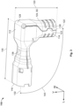
Figure 1 is a perspective view of an angled connector according to an embodiment; -
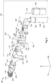
Figure 2 is an exploded perspective view of the angled connector; -
Figure 3 is a perspective view of an angled shield of the angled connector; -
Figure 4A is a perspective view of a cable of the angled connector connected to contacts of the angled connector; -
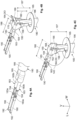
Figure 4B is a perspective view of the cable and an angled dielectric of the angled connector with a dielectric cover of the angled dielectric in an open dielectric position; -
Figure 4C is a perspective view of the cable and the angled dielectric with the dielectric cover in a closed dielectric position; -
Figure 4D is a perspective view of the cable with the angled dielectric in the angled shield, with a shield cover of the angled shield in an open shield position; -
Figure 4E is a perspective view of the cable in the angled shield with the shield cover in a closed shield position; -
Figure 4F is a perspective view of the cable in the angled shield with the shield cover in the closed shield position and a braid of the cable disposed over a first shield section of the angled shield; -
Figure 5 is a sectional side view of the angled connector; and -
Figure 6 is a sectional top view of the angled connector. - An
angled connector 10 according to an embodiment, as shown inFigure 1 , includes anangled subassembly 100 and amating subassembly 200 connected to theangled subassembly 100. - The
angled subassembly 100, as shown inFigures 1 ,2 ,5 , and6 , includes anangled shield 110, an angled dielectric 150 disposed in theangled shield 110, acable 180 disposed in theangled shield 110, acontact 190 electrically connected to thecable 180, and aferrule 196 disposed around thecable 180 and theangled shield 110. - As shown in
Figure 3 , theangled shield 110 has ashield body 112 extending from afirst end 114 to an oppositesecond end 116. Theangled shield 110 has afirst shield section 120 and asecond shield section 130 extending from thefirst shield section 120. - The
first shield section 120, as shown inFigure 3 , extends from thefirst end 114 of theshield body 112. Thefirst shield section 120 has afirst shield axis 122 extending centrally through thefirst shield section 120. In the shown embodiment, thefirst shield axis 122 extends along a vertical direction V. - The
second shield section 130 extends from thefirst shield section 120 to thesecond end 116 of theshield body 112, as shown inFigure 3 . Thesecond shield section 120 has asecond shield axis 132 extending centrally through thesecond shield section 120. In the shown embodiment, thesecond shield axis 132 extends along a longitudinal direction L perpendicular to the vertical direction V. - As shown in
Figure 3 , due to the direction of extension of thesecond shield axis 132 with respect to thefirst shield axis 122, thesecond shield section 130 extends at abend angle 140 with respect to thefirst shield section 120. In the shown embodiment, thebend angle 140 is 90° and thesecond shield section 130 extends perpendicularly with respect to thefirst shield section 120. In other embodiments, thebend angle 140 can be any angle greater than 90° and less than 180°, and thesecond shield section 130 can extend at angles between 90° and 180° with respect to thefirst shield section 120. - In the
first shield section 120, as shown inFigures 2 and3 , theangled shield 110 has ashield cover 124 attached to theshield body 112 at ashield hinge 128. Theshield cover 124 is pivotable with respect to theshield body 112 about theshield hinge 128 between an open shield position SO, shown inFigure 2 , and a closed shield position SC, as shown inFigure 3 . In the embodiment shown inFigures 2 and3 , theshield body 112 has atab 123 in thefirst shield section 120 and theshield cover 124 has arecess 126 extending into theshield cover 124. When theshield cover 124 is pivoted into the closed shield position SC, as shown inFigure 3 , thetab 123 enters therecess 126 and secures theshield cover 124 in the closed shield position SC. - In the
second shield section 130, as shown inFigure 5 , theangled shield 110 has a narrowedportion 134 in which a dimension of aninterior space 135 of thesecond shield section 130 is decreased along the vertical direction V. In the shown embodiment, the narrowedportion 134 is formed by a pair ofprotrusions 136, as shown inFigures 1 ,3 , and5 , extending into theinterior space 135 of thesecond shield section 130 opposite one another in the vertical direction V. In another embodiment, thenarrowed portion 134 can be formed by oneprotrusion 136 extending in the vertical direction V, or could be formed by any other bend or element of theshield body 112 that can decrease the dimension of theinterior space 135. A dimension of the narrowedportion 134 along the longitudinal direction L shown inFigure 3 is merely exemplary; in other embodiments in which thesecond shield section 130 has a larger dimension along the longitudinal direction L, thenarrowed portion 134 may also have a longer dimension along the longitudinal direction L. - The
angled shield 110 is formed of a conductive material, such as aluminum, and in an embodiment is monolithically formed in a single piece with at least theshield body 112, thefirst section 120, thesecond section 130, and theshield cover 124. Theangled shield 110 may be formed by stamping and bending from a sheet of conductive material. In other embodiments, theangled shield 110 may be formed from a plurality of separate elements attached together. - The angled dielectric 150, as shown in
Figure 2 , has adielectric body 152 extending from afirst end 154 to an oppositesecond end 156. The angled dielectric 150 has a firstdielectric section 160 and a seconddielectric section 170 extending from the firstdielectric section 160. - The first
dielectric section 160, as shown inFigure 2 , extends from thefirst end 154 of thedielectric body 152. The firstdielectric section 160 has a firstdielectric axis 162 extending centrally through the firstdielectric section 160. In the shown embodiment, the firstdielectric axis 162 extends along the vertical direction V. - The second
dielectric section 170 extends from the firstdielectric section 160 to thesecond end 156 of thedielectric body 152, as shown inFigure 2 . The seconddielectric section 170 has a seconddielectric axis 172 extending centrally through the seconddielectric section 170. In the shown embodiment, the seconddielectric axis 172 extends along the longitudinal direction L. - As shown in
Figure 2 , due to the direction of extension of the seconddielectric axis 172 with respect to the firstdielectric axis 162, the seconddielectric section 170 extends at thebend angle 140 with respect to the firstdielectric section 160. Thebend angle 140 of the seconddielectric section 170 with respect to the firstdielectric section 160 is the same as thebend angle 140 of thesecond shield section 130 with respect to thefirst shield section 120; thebend angle 140 of the seconddielectric section 170 with respect to the firstdielectric section 160 is greater than or equal to 90° and less than 180°. - In the first
dielectric section 160, as shown inFigure 2 , the angled dielectric 150 has adielectric cover 164 attached to thedielectric body 152 at adielectric hinge 168. Thedielectric cover 164 is pivotable with respect to thedielectric body 152 about thedielectric hinge 168 between an open dielectric position DO, shown inFigures 2 and4B , and a closed dielectric position DC, shown inFigure 4C . - In the embodiment shown in
Figures 2 ,4B, and 4C , thedielectric body 152 has acatch 158 in the firstdielectric section 160 and thedielectric cover 164 has alatch 166. When thedielectric cover 164 is pivoted into the closed dielectric position DC, thelatch 166 engages with thecatch 158 and secures thedielectric cover 164 in the closed dielectric position DC. In the shown embodiment, thecatch 158 is a recess and thelatch 166 is a protrusion complementary to the recess of thecatch 158. In other embodiments, thecatch 158 may be a protrusion and thelatch 166 may be a recess complementary to the protrusion of thecatch 158, or thecatch 158 and thelatch 166 may be any other elements capable of engaging with one another to secure thedielectric cover 164 in the closed dielectric position DC. In another embodiment, thecatch 158 and thelatch 166 may be omitted. - The angled dielectric 150 is a dielectric material, such as a plastic, and in an embodiment is monolithically formed in a single piece with at least the
dielectric body 152, the firstdielectric section 160, the seconddielectric section 170, and thedielectric cover 164; in this embodiment, thedielectric hinge 168 is a film hinge. In other embodiments, the angled dielectric 150 may be formed from a plurality of separate elements attached together. - The
cable 180, as shown inFigure 2 , has awire 183, afoil 184 disposed around thewire 183, abraid 185 disposed around thefoil 184, and acable insulation 186 disposed around thebraid 185. - In the shown embodiment, the
cable 180 includes a twisted pair ofwires 183, with each of thewires 183 having aconductor 183a and awire insulation 183b disposed around theconductor 183a. In the twisted pair embodiment, thewires 183 are twisted around one another within thefoil 184 with thewire insulation 183b of each of thewires 183 in abutment with one another. In another embodiment, thecable 180 includes a pair ofwires 183 extending parallel to one another, each of thewires 183 having theconductor 183a and thewire insulation 183b. In another embodiment, thecable 180 may have onewire 183 with oneconductor 183a surrounded by onewire insulation 183b. - The
foil 184 is disposed around thewires 183 orwire 183 in abutment with thewire insulation 183b, as shown inFigure 2 . Thefoil 184 is formed of a conductive material. Thebraid 185 is disposed around and in abutment with thefoil 184; thebraid 185 is formed of a conductive material. Thecable insulation 186, formed of an insulative material, is disposed around and in abutment with thebraid 185. - The
contact 190, as shown inFigure 2 , has amating portion 192 and aconnection portion 194 at an end opposite themating portion 192. Thecontact 190 is formed of a conductive material. In the shown embodiment, themating portion 192 is a receptacle for a pin; in other embodiments, themating portion 192 could be a pin or any other type of contact element capable of mating with another contact element. In the shown embodiment, theconnection portion 194 is a crimping portion capable of being crimped to a conductor. In other embodiments, theconnection portion 194 could be a flat element capable of being welded to a conductor, or any other type of element capable of mechanically and electrically connecting thecontact 190 to a conductor. Theangled subassembly 100 has twocontacts 190 in the shown embodiment. The number ofcontacts 190 corresponds to the number ofwires 183 of thecable 180; theangled subassembly 100 may alternatively have onecontact 190 for an embodiment of thecable 180 having onewire 183. - The
ferrule 196, as shown in the embodiment ofFigures 1 and2 , is an approximately cylindrical element formed of a conductive material. In an embodiment, theferrule 196 is formed from bending or rolling a sheet of conductive material. - The
mating subassembly 200, as shown inFigures 1 and2 , includes amating shield 210 and amating dielectric 220 disposed within themating shield 210. Themating shield 210, formed of a conductive material, extends from afirst end 212 to an oppositesecond end 214 along the longitudinal direction L. Themating shield 210 has a plurality of contact springs 216 disposed adjacent to thefirst end 212. In an embodiment, themating shield 210 is monolithically formed in a single piece. Themating dielectric 220 is formed of a dielectric material and, as shown inFigure 6 , has a plurality ofcontact receiving passageways 222 extending through themating dielectric 220 along the longitudinal direction L. Themating dielectric 220 can alternatively have one or more than twocontact receiving passageways 222; the number ofcontact receiving passageways 222 corresponds to the number ofwires 183 of thecable 180 and the number ofcontacts 190. - The assembly of the
angled connector 10 will now be described primarily with respect toFigures 4A-4F . - In a first step, shown in
Figure 4A , thecable insulation 186, thebraid 185, and thefoil 184 are stripped to expose thewires 183. For each of thewires 183, a portion of thewire insulation 183b is stripped to expose a portion of theconductor 183a. Theconnection portion 194 of each of thecontacts 190 is electrically and mechanically connected to one of the exposedconductors 183a. In the embodiment shown inFigure 4A , theconnections portions 194 are crimped to theconductors 183a. - In a next step, shown in
Figure 4B , thecable 180 is inserted into and through theangled dielectric 150 with thedielectric cover 164 in the open dielectric position DO. Thecable 180 is bent within theangled dielectric 150 as shown inFigures 2 and4B . When thecable 180 is bent, thecable 180 has afirst portion 187 and asecond portion 188 extending at thebend angle 140 with respect to thefirst portion 187, as shown inFigure 4C . Thefirst portion 187 is disposed in the firstdielectric section 160 and thesecond portion 188 is disposed in thesecond dielectric section 170. As shown inFigure 4B , thewires 183 and thefoil 184 of thecable 180 extend through theangled dielectric 150. - With the
cable 180 fully inserted through theangled dielectric 150 and bent into the shape described above and shown inFigures 2 and4B , thedielectric cover 164 is moved from the open dielectric position DO to the closed dielectric position DC shown inFigure 4C . In an embodiment, thecatch 158 engages thelatch 166 to secure thedielectric cover 164 in the closed dielectric position DC. In another embodiment, in lieu of or in addition to thecatch 158 and thelatch 166, thedielectric cover 164 is secured to thedielectric body 152 in the closed dielectric position DC by plastic welding of thedielectric cover 164 to thedielectric body 152. In another embodiment, theangled dielectric 150 does not have thedielectric cover 164 pivotable with respect to thedielectric body 152, but rather is overmolded in a single piece over thefoil 184 of thecable 180 in the position shown inFigure 4C . - The
angled dielectric 150 in the position shown inFigure 4C , due to the structure and thebend angle 140 of the firstdielectric section 160 with respect to thesecond dielectric section 170 shown inFigures 2 and4B , secures thecable 180 in the position shown inFigure 4C with thefirst portion 187 at thesame bend angle 140 with respect to thesecond portion 188. In the shown embodiment, thecable 180 is inserted into theangled dielectric 150 to be bent and held with thecontacts 190 already connected to thewires 183. In another embodiment, thecable 180 can be inserted into theangled dielectric 150, bent, and held by theangled dielectric 150 prior to connecting thecontacts 190 with thewires 183. - In an embodiment shown in
Figure 4D , thecable 180 bent and held by theangled dielectric 150 is inserted into theangled shield 110 with theshield cover 124 in the open shield position SO. In the position shown inFigure 4D , thebraid 185 is flared outwards from thecable 180. - The
shield cover 124 is then moved from the open shield position SO shown inFigure 4D to the closed shield position SC shown inFigure 4E , enclosing thecable 180 in theshield body 112. In the shown embodiment, thetab 123 is disposed in therecess 126 to secure theshield cover 124 in the closed shield position SC. In an embodiment, theshield cover 124 can be crimped to theshield body 112 to retain theshield cover 124 in the closed shield position SC. In other embodiments, including thetab 123 and therecess 126 or omitting thetab 123 and therecess 126, and in addition to or in lieu of crimping theshield cover 124 to theshield body 112, theshield cover 124 can be welded to theshield body 112 to secure theshield cover 124 in the closed shield position SC. - With the
shield cover 124 in the closed shield position SC shown inFigure 4E , thebraid 185 is dressed or folded over thefirst shield section 120 of theangled shield 110, as shown inFigure 4F . Theferrule 196 is then positioned over the exposed portion of thebraid 185 and a portion of thecable insulation 186 and crimped over thebraid 185, thefirst shield section 120, and thecable insulation 186, as shown inFigures 1 and5 . - In the embodiment shown in
Figures 4D-4F , themating subassembly 200 is already connected to theangled shield 110 when theangled dielectric 150 and thecable 180 are inserted into theangled shield 110. As shown inFigures 5 and6 , thesecond end 116 of theangled shield 110 at thesecond shield section 130 is inserted into thesecond end 214 of themating shield 210 and disposed in themating shield 210. Theangled shield 110 is mechanically and electrically connected to themating shield 210 through thesecond shield section 130. Themating dielectric 220 is disposed within theinterior space 135 of thesecond shield section 130, as shown inFigures 5 and6 . Themating dielectric 220 extends from a position adjacent to the narrowedportion 134 and out of thesecond shield section 130 along the longitudinal direction L. In another embodiment, themating subassembly 200 can be connected to theangled shield 110 after theangled dielectric 150 and thecable 180 are inserted into theangled shield 110. - The
angled connector 10 is shown in a fully assembled state inFigures 1 ,5 , and6 in which thecable 180 is disposed and held within theangled shield 110 and theangled dielectric 150. - As shown in
Figure 5 , thefirst portion 187 of thecable 180 is positioned in thefirst shield section 120 of theangled shield 110 and in the firstdielectric section 160 of theangled dielectric 150. Thefoil 184 is disposed around thewires 183 in thefirst portion 187 and is held in abutment against thewire insulation 183b of thewires 183. Thefirst shield section 120 mechanically and electrically contacts thefoil 184 in thefirst portion 187 and is disposed between thefoil 184 and thebraid 185. Thebraid 185 in thefirst portion 187 is crimped to thefirst shield section 120 by theferrule 196 and is disposed between thefirst shield section 120 and theferrule 196; in an embodiment, thefirst shield section 120 provides a support for crimping of theferrule 196 around thebraid 185 and thecable 180 that prevents the crimping of theferrule 196 from damaging thefoil 194 or thewires 183. - The
second portion 188 of thecable 180, as shown inFigures 5 and6 , is positioned in thesecond shield section 130 of theangled shield 110 and in thesecond dielectric section 170 of theangled dielectric 150. Thefoil 184 is disposed around thewires 183 in thesecond portion 188 and is held in abutment against thewire insulation 183b of thewires 183; thewires 183 and thefoil 184 are each disposed in thefirst portion 187 and thesecond portion 188 of thecable 180. - In the
second portion 188, as shown inFigure 5 , thewire insulation 183b of thewires 183 is disposed in the narrowedportion 134 of theangled shield 110. In an embodiment, the narrowedportion 134 is smaller in the vertical direction V than an outer diameter of thewires 183 and thecable 180 and thefoil 134 are held in thesecond shield section 130 by an interference fit between thesecond portion 188 of thecable 180 and the narrowedportion 134. Thefoil 134 terminates to theangled shield 110 at the narrowedportion 134. In the shown embodiment, theprotrusions 136 abut thewire insulation 183b to secure thewires 183 in theangled shield 110. - As shown in
Figure 6 , each of thecontacts 190 is positioned and held in one of thecontact receiving passageways 222 of themating dielectric 220. Theconductors 183a of thewires 183 electrically and mechanically connected to theconnection portions 194 of thecontacts 190 are disposed within themating dielectric 220 and themating portions 192 of thecontact 190 opposite theconnection portions 194 are disposed adjacent to thefirst end 212 of themating shield 210. - In the fully assembled state shown in
Figures 1 ,5 , and6 , thefoil 184 of thecable 180, theangled shield 110, thebraid 185, theferrule 196, and themating shield 210 are electrically connected. Theconductors 183a of thewires 183 are electrically connected to thecontacts 190 and are electrically isolated from thefoil 184, theangled shield 110, thebraid 185, and themating shield 210 by thewire insulations 183b and themating dielectric 220. When theangled connector 10 is connected with a mating connector, the contact springs 216 of themating shield 210 resiliently abut and electrically connect with a shield of the mating connector, and thecontacts 190 mate and electrically connect with contacts of the mating connector. - In the
angled connector 10, thecable 180 extends through a bend with thefirst portion 187 held at thebend angle 140 with respect to thesecond portion 188 by theangled shield 110 and theangled dielectric 150. By having the bend in thecable 180 itself, thefoil 184 can remain over a longer portion of thecable 180 in theangled connector 10, allowing for a high degree of impedance control and improved shielding performance. Thefoil 184 extending over a large portion of thecable 180 and through the bend also avoids the crimping of theferrule 196 having a significant impact on the impedance control; theferrule 196 can be crimped as tight as necessary for mechanical robustness and as described above, can bear on thefirst shield section 120 instead of potentially damaging thefoil 184. Simple designs of thecontact 190 can be used with theangled connector 10, saving on component cost and decreasing the complexity of assembly. - In the shown embodiment, the
angled dielectric 150 maintains a tight fit of the wire orwires 183 within theangled shield 110 and a tight wrap of thefoil 184 around thewires 183 in thefirst portion 187 and thesecond portion 188. In another embodiment, theangled dielectric 150 can be omitted. In an embodiment omitting theangled dielectric 150, the other elements of theangled connector 10 are still arranged as described above; thecable 180 extends through theangled shield 110 with thefirst portion 187 and thesecond portion 188 still at thebend angle 140, and the narrowedportion 134 of thesecond shield section 130 is relied upon to maintain the tightness of thewires 183 with each other and the tight wrap of thefoil 184. - The
angled connector 10 in the shown embodiment holds thefirst portion 187 of thecable 180 with respect to thesecond portion 188 of thecable 180 on the opposite side of the bend at thebend angle 140 of 90°. In other embodiments, thebend angle 140 can be any angle greater than 90° and less than 180°. Thecable 180 in the shown embodiment also has a particular rotational position with respect to thecontacts 190 about a rotational axis of the longitudinal direction L. Theangled connector 10 is not limited to the rotational position of the shown embodiment, and thecable 180 could be arranged and held by theangled subassembly 100 at any rotational position about the longitudinal axis L with respect to thecontacts 190. - Various aspects and embodiments of the invention are defined in the following numbered clauses:
- Clause 1. An angled subassembly (100) of an angled connector (10), comprising:
- an angled shield (110) having a first shield section (120) and a second shield section (130) extending at a bend angle (140) with respect to the first shield section (120); and
- a cable (180) disposed in the angled shield (110), the cable (180) having a first portion (187) positioned in the first shield section (120) and a second portion (188) positioned in the second shield section (130), the second portion (188) extending at the bend angle (140) with respect to the first portion (187).
- Clause 2. The angled subassembly (100) of Clause 1, wherein the cable (180) has a wire (183) and a foil (184) disposed around the wire (183), the wire (183) and the foil (184) are each disposed in the first portion (187) and in the second portion (188) of the cable (180).
- Clause 3. The angled subassembly (100) of Clause 2, wherein the wire (183) has a conductor (183a) disposed within a wire insulation (183b), the foil (184) abuts the wire insulation (183b) in the first portion (187) and in the second portion (188) of the cable (180).
- Clause 4. The angled subassembly (100) of Clause 1, wherein the angled shield (110) has a narrowed portion (134) in the second shield section (130), the narrowed portion (134) has an interference fit with the second portion (188) of the cable (180).
- Clause 5. The angled subassembly (100) of Clause 1, wherein the angled shield (110) has a shield body (112) and a shield cover (124) attached to the shield body (112), the shield cover (124) is pivotable with respect to the shield body (112) between an open shield position (SO) in which the cable (180) is insertable into the shield body (112) and a closed shield position (SC) enclosing the cable (180) in the shield body (112).
- Clause 6. The angled subassembly (100) of Clause 2, further comprising a ferrule (196) disposed around the cable (180) and the first shield section (120).
- Clause 7. The angled subassembly (100) of Clause 6, wherein the first shield section (120) is disposed between the ferrule (196) and the foil (184).
- Clause 8. The angled subassembly (100) of Clause 7, wherein the cable (180) has a braid (185) disposed around the foil (184), the braid (185) is disposed between the first shield section (120) and the ferrule (196).
- Clause 9. The angled subassembly (100) of Clause 2, further comprising an angled dielectric (150) disposed within the angled shield (110), the wire (183) and the foil (184) of the cable (180) extend through the angled dielectric (150), the angled dielectric (150) has a first dielectric section (160) and a second dielectric section (170) extending at the bend angle (140) with respect to the first dielectric section (160), the first portion (187) of the cable (180) is disposed in the first dielectric section (160) and the second portion (188) of the cable (180) is disposed in the second dielectric section (170).
-
Clause 10. The angled subassembly (100) of Clause 9, wherein the angled dielectric (150) has a dielectric body (152) and a dielectric cover (164) attached to the dielectric body (152), the dielectric cover (164) is pivotable with respect to the dielectric body (152) between an open dielectric position (DO) in which the cable (180) is insertable into the dielectric body (152) and a closed dielectric position (DC) securing the cable (180) in the dielectric body (152). - Clause 11. An angled connector (10), comprising:
- an angled subassembly (100) including an angled shield (110) and a cable (180) disposed in the angled shield (110), the angled shield (110) having a first shield section (120) and a second shield section (130) extending at a bend angle (140) with respect to the first shield section (120), the cable (180) having a first portion (187) positioned in the first shield section (120) and a second portion (188) positioned in the second shield section (130), the second portion (188) extending at the bend angle (140) with respect to the first portion (187); and
- a mating subassembly (200) connected to the angled subassembly (100).
- Clause 12. The angled connector (10) of Clause 11, wherein the mating subassembly (200) has a mating shield (210) electrically connected to the angled shield (110).
- Clause 13. A method of assembling an angled subassembly (100) of a connector (10), comprising:
- providing an angled shield (110) having a first shield section (120) and a second shield section (130) extending at a bend angle (140) with respect to the first shield section (120); and
- inserting a cable (180) into and through the angled shield (110), the cable (180) having a first portion (187) positioned in the first shield section (120) and a second portion (188) positioned in the second shield section (130), the second portion (188) extending at the bend angle (140) with respect to the first portion (187).
- Clause 14. The method of Clause 13, wherein the cable (180) has a wire (183) and a foil (184) disposed around the wire (183), the wire (183) and the foil (184) are each disposed in the first portion (187) and in the second portion (188) of the cable (180).
- Clause 15. The method of Clause 14, wherein the cable (180) has a braid (185) disposed around the foil (184), and further comprising crimping a ferrule (196) around the braid (185) and the first shield section (120).
Claims (10)
- An angled subassembly (100) of an angled connector (10), comprising:an angled shield (110) having a first shield section (120) and a second shield section (130) extending at a bend angle (140) with respect to the first shield section (120);a cable (180) disposed in the angled shield (110), the cable (180) having a first portion (187) positioned in the first shield section (120) and a second portion (188) positioned in the second shield section (130), the second portion (188) extending at the bend angle (140) with respect to the first portion (187), wherein the cable (180) has a wire (183) and a foil (184) disposed around the wire (183), the wire (183) and the foil (184) are each disposed in the first portion (187) and in the second portion (188) of the cable (180); andan angled dielectric (150) disposed within the angled shield (110), the wire (183) and the foil (184) of the cable (180) extend through the angled dielectric (150), the angled dielectric (150) has a first dielectric section (160) and a second dielectric section (170) extending at the bend angle (140) with respect to the first dielectric section (160), the first portion (187) of the cable (180) is disposed in the first dielectric section (160) and the second portion (188) of the cable (180) is disposed in the second dielectric section (170).
- The angled subassembly (100) of claim 1, wherein the wire (183) has a conductor (183a) disposed within a wire insulation (183b), the foil (184) abuts the wire insulation (183b) in the first portion (187) and in the second portion (188) of the cable (180).
- The angled subassembly (100) of claim 1, wherein the angled shield (110) has a narrowed portion (134) in the second shield section (130), the narrowed portion (134) has an interference fit with the second portion (188) of the cable (180).
- The angled subassembly (100) of claim 1, wherein the angled shield (110) has a shield body (112) and a shield cover (124) attached to the shield body (112), the shield cover (124) is pivotable with respect to the shield body (112) between an open shield position (SO) in which the cable (180) is insertable into the shield body (112) and a closed shield position (SC) enclosing the cable (180) in the shield body (112).
- The angled subassembly (100) of claim 1, further comprising a ferrule (196) disposed around the cable (180) and the first shield section (120).
- The angled subassembly (100) of claim 5, wherein the first shield section (120) is disposed between the ferrule (196) and the foil (184).
- The angled subassembly (100) of claim 6, wherein the cable (180) has a braid (185) disposed around the foil (184), the braid (185) is disposed between the first shield section (120) and the ferrule (196).
- The angled subassembly (100) of claim 1, wherein the angled dielectric (150) has a dielectric body (152) and a dielectric cover (164) attached to the dielectric body (152), the dielectric cover (164) is pivotable with respect to the dielectric body (152) between an open dielectric position (DO) in which the cable (180) is insertable into the dielectric body (152) and a closed dielectric position (DC) securing the cable (180) in the dielectric body (152).
- An angled connector (10), comprising the angled subassembly (100) of claim 1 and a mating subassembly (200) connected to the angled subassembly (100).
- The angled connector (10) of claim 9, wherein the mating subassembly (200) has a mating shield (210) electrically connected to the angled shield (110).
Applications Claiming Priority (3)
| Application Number | Priority Date | Filing Date | Title |
|---|---|---|---|
| US17/708,878 US12283776B2 (en) | 2022-03-30 | 2022-03-30 | Angled subassembly for an angled connector |
| PCT/US2023/016986 WO2023192532A1 (en) | 2022-03-30 | 2023-03-30 | Angled subassembly for an angled connector and method of assembling thereof |
| EP23719982.3A EP4500643A1 (en) | 2022-03-30 | 2023-03-30 | Angled subassembly for an angled connector and method of assembling thereof |
Related Parent Applications (1)
| Application Number | Title | Priority Date | Filing Date |
|---|---|---|---|
| EP23719982.3A Division EP4500643A1 (en) | 2022-03-30 | 2023-03-30 | Angled subassembly for an angled connector and method of assembling thereof |
Publications (2)
| Publication Number | Publication Date |
|---|---|
| EP4535574A2 true EP4535574A2 (en) | 2025-04-09 |
| EP4535574A3 EP4535574A3 (en) | 2025-06-25 |
Family
ID=86226591
Family Applications (2)
| Application Number | Title | Priority Date | Filing Date |
|---|---|---|---|
| EP23719982.3A Pending EP4500643A1 (en) | 2022-03-30 | 2023-03-30 | Angled subassembly for an angled connector and method of assembling thereof |
| EP25159775.3A Pending EP4535574A3 (en) | 2022-03-30 | 2023-03-30 | Angled subassembly for an angled connector and method of assembling thereof |
Family Applications Before (1)
| Application Number | Title | Priority Date | Filing Date |
|---|---|---|---|
| EP23719982.3A Pending EP4500643A1 (en) | 2022-03-30 | 2023-03-30 | Angled subassembly for an angled connector and method of assembling thereof |
Country Status (7)
| Country | Link |
|---|---|
| US (2) | US12283776B2 (en) |
| EP (2) | EP4500643A1 (en) |
| JP (1) | JP2025510886A (en) |
| KR (1) | KR102971754B1 (en) |
| CN (1) | CN118947027A (en) |
| MX (1) | MX2024011928A (en) |
| WO (1) | WO2023192532A1 (en) |
Families Citing this family (3)
| Publication number | Priority date | Publication date | Assignee | Title |
|---|---|---|---|---|
| CN117977269B (en) * | 2024-01-19 | 2025-09-02 | 中航光电科技股份有限公司 | Corner connector outer conductor, corner connector insulator and corner RF connector |
| DE102024112725A1 (en) * | 2024-05-06 | 2025-11-06 | Kromberg & Schubert Automotive Gmbh & Co. Kg | Shielded connector, connector arrangement and assembly method of the connector arrangement |
| CN119812857B (en) * | 2024-11-29 | 2025-10-28 | 中航光电科技股份有限公司 | Curved high-speed connector |
Family Cites Families (15)
| Publication number | Priority date | Publication date | Assignee | Title |
|---|---|---|---|---|
| US4173386A (en) * | 1978-03-13 | 1979-11-06 | W. L. Gore & Associates, Inc. | Coaxial assembly |
| US5362255A (en) * | 1993-09-14 | 1994-11-08 | Itt Corporation | Coaxial connector |
| DE10118258A1 (en) * | 2001-04-11 | 2002-11-21 | Christian Schwaiger Gmbh & Co | Switchable and lockable, coaxial connector |
| DE60313538T2 (en) * | 2002-07-02 | 2008-01-10 | Tyco Electronics Amp Gmbh | Coaxial angle connector |
| US6817899B1 (en) * | 2003-04-09 | 2004-11-16 | Yazaki North America, Inc. | Angled connector for coaxial cable |
| DE102004029300B4 (en) * | 2003-06-25 | 2024-10-17 | Te Connectivity Germany Gmbh | coaxial connectors |
| JP2006004820A (en) * | 2004-06-18 | 2006-01-05 | Yazaki Corp | Shield terminal for coaxial cable |
| DE102006012194A1 (en) * | 2006-03-16 | 2007-09-20 | Escha Bauelemente Gmbh | Shielded plug e.g. angular plug, connector for use in e.g. automation engineering, has shield designed in fastening area for mesh wire shield such that shield is arranged for mounting around wire fastened at contact unit of insert |
| DE102008004801B4 (en) | 2007-02-02 | 2011-12-08 | Japan Aviation Electronics Industry, Ltd. | Connector and device equipped therewith |
| US7588460B2 (en) * | 2007-04-17 | 2009-09-15 | Thomas & Betts International, Inc. | Coaxial cable connector with gripping ferrule |
| JP5067980B2 (en) * | 2010-10-06 | 2012-11-07 | 日本航空電子工業株式会社 | Coaxial connector |
| US9214743B2 (en) * | 2014-04-25 | 2015-12-15 | Tyco Electronics Corporation | Right angle connector assembly |
| US10468837B2 (en) * | 2016-09-27 | 2019-11-05 | Te Connectivity Corporation | Coaxial connector assembly |
| JP6814080B2 (en) * | 2017-03-23 | 2021-01-13 | ホシデン株式会社 | Manufacturing method of L-type inner terminal, L-type coaxial connector including the L-type inner terminal, and its L-type coaxial connector |
| US10446950B2 (en) | 2017-06-26 | 2019-10-15 | Delphi Technologies, Llc | Method for forming a shielded electrical terminal and an electrical terminal formed by said method |
-
2022
- 2022-03-30 US US17/708,878 patent/US12283776B2/en active Active
-
2023
- 2023-03-30 CN CN202380030406.1A patent/CN118947027A/en active Pending
- 2023-03-30 KR KR1020247036100A patent/KR102971754B1/en active Active
- 2023-03-30 WO PCT/US2023/016986 patent/WO2023192532A1/en not_active Ceased
- 2023-03-30 JP JP2024557115A patent/JP2025510886A/en active Pending
- 2023-03-30 EP EP23719982.3A patent/EP4500643A1/en active Pending
- 2023-03-30 EP EP25159775.3A patent/EP4535574A3/en active Pending
-
2024
- 2024-09-27 MX MX2024011928A patent/MX2024011928A/en unknown
-
2025
- 2025-04-15 US US19/179,032 patent/US20260163305A1/en active Pending
Also Published As
| Publication number | Publication date |
|---|---|
| US20260163305A1 (en) | 2026-06-11 |
| US20230318231A1 (en) | 2023-10-05 |
| US12283776B2 (en) | 2025-04-22 |
| EP4535574A3 (en) | 2025-06-25 |
| JP2025510886A (en) | 2025-04-15 |
| MX2024011928A (en) | 2024-11-08 |
| WO2023192532A1 (en) | 2023-10-05 |
| KR20240163169A (en) | 2024-11-18 |
| CN118947027A (en) | 2024-11-12 |
| EP4500643A1 (en) | 2025-02-05 |
| KR102971754B1 (en) | 2026-06-01 |
Similar Documents
| Publication | Publication Date | Title |
|---|---|---|
| EP4539264A2 (en) | Angled subassembly for an angled connector and method of assembling thereof | |
| US20230223724A1 (en) | Contact member for electrical connector | |
| WO2023192532A1 (en) | Angled subassembly for an angled connector and method of assembling thereof | |
| EP3584891B1 (en) | Shield connector and shield cable assembly with a terminal | |
| EP0542075B1 (en) | Method of terminating miniature coaxial electrical connector and resulting terminated connector | |
| CN117977269A (en) | Corner connector outer conductor, corner connector insulator and corner radio frequency connector | |
| JPH07106003A (en) | Modular coaxial cable connector and assembly method thereof | |
| JPH07192819A (en) | Coaxial connector | |
| EP3340395B1 (en) | Connector and production method thereof | |
| JP3186021B2 (en) | Connector for coaxial cable and method of manufacturing the same | |
| JP3425634B2 (en) | Electrical connector with shield termination for high-speed cables | |
| US12586959B2 (en) | Angled connector | |
| US20240313488A1 (en) | Multi-piece coaxial plug connector with variably configurable interface geometry | |
| US11996657B2 (en) | Connector including male and female connectors | |
| US11462342B2 (en) | Cable harness assembly with a shielded twisted pair cable | |
| JP3824269B2 (en) | Wire connector | |
| KR0138837B1 (en) | Terminal position assurance system for electrical connectors | |
| JP3344622B2 (en) | Shielded wire connector | |
| JP7644076B2 (en) | connector | |
| EP2019450A1 (en) | Connector for coaxial cable | |
| JP7644077B2 (en) | connector | |
| JP2001283991A (en) | L-type multi-core cable connector | |
| JP2025158082A (en) | Shielded Connector |
Legal Events
| Date | Code | Title | Description |
|---|---|---|---|
| PUAI | Public reference made under article 153(3) epc to a published international application that has entered the european phase |
Free format text: ORIGINAL CODE: 0009012 |
|
| STAA | Information on the status of an ep patent application or granted ep patent |
Free format text: STATUS: THE APPLICATION HAS BEEN PUBLISHED |
|
| AC | Divisional application: reference to earlier application |
Ref document number: 4500643 Country of ref document: EP Kind code of ref document: P |
|
| AK | Designated contracting states |
Kind code of ref document: A2 Designated state(s): AL AT BE BG CH CY CZ DE DK EE ES FI FR GB GR HR HU IE IS IT LI LT LU LV MC ME MK MT NL NO PL PT RO RS SE SI SK SM TR |
|
| REG | Reference to a national code |
Ref country code: DE Ref legal event code: R079 Free format text: PREVIOUS MAIN CLASS: H01R0009050000 Ipc: H01R0013659300 |
|
| PUAL | Search report despatched |
Free format text: ORIGINAL CODE: 0009013 |
|
| AK | Designated contracting states |
Kind code of ref document: A3 Designated state(s): AL AT BE BG CH CY CZ DE DK EE ES FI FR GB GR HR HU IE IS IT LI LT LU LV MC ME MK MT NL NO PL PT RO RS SE SI SK SM TR |
|
| RIC1 | Information provided on ipc code assigned before grant |
Ipc: H01R 9/05 20060101ALN20250520BHEP Ipc: H01R 13/50 20060101ALN20250520BHEP Ipc: H01R 4/20 20060101ALN20250520BHEP Ipc: H01R 13/6591 20110101ALI20250520BHEP Ipc: H01R 13/6593 20110101AFI20250520BHEP |
|
| STAA | Information on the status of an ep patent application or granted ep patent |
Free format text: STATUS: REQUEST FOR EXAMINATION WAS MADE |
|
| 17P | Request for examination filed |
Effective date: 20250804 |
|
| GRAP | Despatch of communication of intention to grant a patent |
Free format text: ORIGINAL CODE: EPIDOSNIGR1 |
|
| STAA | Information on the status of an ep patent application or granted ep patent |
Free format text: STATUS: GRANT OF PATENT IS INTENDED |
|
| RIC1 | Information provided on ipc code assigned before grant |
Ipc: H01R 13/6593 20110101AFI20260529BHEP Ipc: H01R 13/6591 20110101ALI20260529BHEP Ipc: H01R 4/20 20060101ALN20260529BHEP Ipc: H01R 13/50 20060101ALN20260529BHEP Ipc: H01R 9/05 20060101ALN20260529BHEP |
|
| RIC1 | Information provided on ipc code assigned before grant |
Ipc: H01R 13/6593 20110101AFI20260609BHEP Ipc: H01R 13/6591 20110101ALI20260609BHEP Ipc: H01R 4/20 20060101ALN20260609BHEP Ipc: H01R 13/50 20060101ALN20260609BHEP Ipc: H01R 9/05 20060101ALN20260609BHEP |
|
| INTG | Intention to grant announced |
Effective date: 20260617 |