EP4535519A1 - Spacer for battery cell, battery cell, battery pack, and vehicle - Google Patents
Spacer for battery cell, battery cell, battery pack, and vehicle Download PDFInfo
- Publication number
- EP4535519A1 EP4535519A1 EP23909658.9A EP23909658A EP4535519A1 EP 4535519 A1 EP4535519 A1 EP 4535519A1 EP 23909658 A EP23909658 A EP 23909658A EP 4535519 A1 EP4535519 A1 EP 4535519A1
- Authority
- EP
- European Patent Office
- Prior art keywords
- spacer
- battery cell
- pressure relief
- groove
- present disclosure
- Prior art date
- Legal status (The legal status is an assumption and is not a legal conclusion. Google has not performed a legal analysis and makes no representation as to the accuracy of the status listed.)
- Pending
Links
Images




Classifications
-
- H—ELECTRICITY
- H01—ELECTRIC ELEMENTS
- H01M—PROCESSES OR MEANS, e.g. BATTERIES, FOR THE DIRECT CONVERSION OF CHEMICAL ENERGY INTO ELECTRICAL ENERGY
- H01M50/00—Constructional details or processes of manufacture of the non-active parts of electrochemical cells other than fuel cells, e.g. hybrid cells
- H01M50/50—Current conducting connections for cells or batteries
- H01M50/572—Means for preventing undesired use or discharge
- H01M50/584—Means for preventing undesired use or discharge for preventing incorrect connections inside or outside the batteries
- H01M50/59—Means for preventing undesired use or discharge for preventing incorrect connections inside or outside the batteries characterised by the protection means
- H01M50/593—Spacers; Insulating plates
-
- H—ELECTRICITY
- H01—ELECTRIC ELEMENTS
- H01M—PROCESSES OR MEANS, e.g. BATTERIES, FOR THE DIRECT CONVERSION OF CHEMICAL ENERGY INTO ELECTRICAL ENERGY
- H01M50/00—Constructional details or processes of manufacture of the non-active parts of electrochemical cells other than fuel cells, e.g. hybrid cells
- H01M50/40—Separators; Membranes; Diaphragms; Spacing elements inside cells
- H01M50/471—Spacing elements inside cells other than separators, membranes or diaphragms; Manufacturing processes thereof
- H01M50/477—Spacing elements inside cells other than separators, membranes or diaphragms; Manufacturing processes thereof characterised by their shape
-
- H—ELECTRICITY
- H01—ELECTRIC ELEMENTS
- H01M—PROCESSES OR MEANS, e.g. BATTERIES, FOR THE DIRECT CONVERSION OF CHEMICAL ENERGY INTO ELECTRICAL ENERGY
- H01M50/00—Constructional details or processes of manufacture of the non-active parts of electrochemical cells other than fuel cells, e.g. hybrid cells
- H01M50/10—Primary casings; Jackets or wrappings
- H01M50/147—Lids or covers
- H01M50/148—Lids or covers characterised by their shape
- H01M50/15—Lids or covers characterised by their shape for prismatic or rectangular cells
-
- H—ELECTRICITY
- H01—ELECTRIC ELEMENTS
- H01M—PROCESSES OR MEANS, e.g. BATTERIES, FOR THE DIRECT CONVERSION OF CHEMICAL ENERGY INTO ELECTRICAL ENERGY
- H01M50/00—Constructional details or processes of manufacture of the non-active parts of electrochemical cells other than fuel cells, e.g. hybrid cells
- H01M50/10—Primary casings; Jackets or wrappings
- H01M50/183—Sealing members
- H01M50/186—Sealing members characterised by the disposition of the sealing members
- H01M50/188—Sealing members characterised by the disposition of the sealing members the sealing members being arranged between the lid and terminal
-
- H—ELECTRICITY
- H01—ELECTRIC ELEMENTS
- H01M—PROCESSES OR MEANS, e.g. BATTERIES, FOR THE DIRECT CONVERSION OF CHEMICAL ENERGY INTO ELECTRICAL ENERGY
- H01M50/00—Constructional details or processes of manufacture of the non-active parts of electrochemical cells other than fuel cells, e.g. hybrid cells
- H01M50/30—Arrangements for facilitating escape of gases
- H01M50/342—Non-re-sealable arrangements
-
- H—ELECTRICITY
- H01—ELECTRIC ELEMENTS
- H01M—PROCESSES OR MEANS, e.g. BATTERIES, FOR THE DIRECT CONVERSION OF CHEMICAL ENERGY INTO ELECTRICAL ENERGY
- H01M50/00—Constructional details or processes of manufacture of the non-active parts of electrochemical cells other than fuel cells, e.g. hybrid cells
- H01M50/30—Arrangements for facilitating escape of gases
- H01M50/342—Non-re-sealable arrangements
- H01M50/3425—Non-re-sealable arrangements in the form of rupturable membranes or weakened parts, e.g. pierced with the aid of a sharp member
-
- H—ELECTRICITY
- H01—ELECTRIC ELEMENTS
- H01M—PROCESSES OR MEANS, e.g. BATTERIES, FOR THE DIRECT CONVERSION OF CHEMICAL ENERGY INTO ELECTRICAL ENERGY
- H01M50/00—Constructional details or processes of manufacture of the non-active parts of electrochemical cells other than fuel cells, e.g. hybrid cells
- H01M50/40—Separators; Membranes; Diaphragms; Spacing elements inside cells
- H01M50/471—Spacing elements inside cells other than separators, membranes or diaphragms; Manufacturing processes thereof
- H01M50/474—Spacing elements inside cells other than separators, membranes or diaphragms; Manufacturing processes thereof characterised by their position inside the cells
-
- H—ELECTRICITY
- H01—ELECTRIC ELEMENTS
- H01M—PROCESSES OR MEANS, e.g. BATTERIES, FOR THE DIRECT CONVERSION OF CHEMICAL ENERGY INTO ELECTRICAL ENERGY
- H01M50/00—Constructional details or processes of manufacture of the non-active parts of electrochemical cells other than fuel cells, e.g. hybrid cells
- H01M50/50—Current conducting connections for cells or batteries
- H01M50/572—Means for preventing undesired use or discharge
- H01M50/584—Means for preventing undesired use or discharge for preventing incorrect connections inside or outside the batteries
- H01M50/586—Means for preventing undesired use or discharge for preventing incorrect connections inside or outside the batteries inside the batteries, e.g. incorrect connections of electrodes
-
- H—ELECTRICITY
- H01—ELECTRIC ELEMENTS
- H01M—PROCESSES OR MEANS, e.g. BATTERIES, FOR THE DIRECT CONVERSION OF CHEMICAL ENERGY INTO ELECTRICAL ENERGY
- H01M2220/00—Batteries for particular applications
- H01M2220/20—Batteries in motive systems, e.g. vehicle, ship, plane
-
- H—ELECTRICITY
- H01—ELECTRIC ELEMENTS
- H01M—PROCESSES OR MEANS, e.g. BATTERIES, FOR THE DIRECT CONVERSION OF CHEMICAL ENERGY INTO ELECTRICAL ENERGY
- H01M50/00—Constructional details or processes of manufacture of the non-active parts of electrochemical cells other than fuel cells, e.g. hybrid cells
- H01M50/50—Current conducting connections for cells or batteries
- H01M50/531—Electrode connections inside a battery casing
- H01M50/536—Electrode connections inside a battery casing characterised by the method of fixing the leads to the electrodes, e.g. by welding
-
- Y—GENERAL TAGGING OF NEW TECHNOLOGICAL DEVELOPMENTS; GENERAL TAGGING OF CROSS-SECTIONAL TECHNOLOGIES SPANNING OVER SEVERAL SECTIONS OF THE IPC; TECHNICAL SUBJECTS COVERED BY FORMER USPC CROSS-REFERENCE ART COLLECTIONS [XRACs] AND DIGESTS
- Y02—TECHNOLOGIES OR APPLICATIONS FOR MITIGATION OR ADAPTATION AGAINST CLIMATE CHANGE
- Y02E—REDUCTION OF GREENHOUSE GAS [GHG] EMISSIONS, RELATED TO ENERGY GENERATION, TRANSMISSION OR DISTRIBUTION
- Y02E60/00—Enabling technologies; Technologies with a potential or indirect contribution to GHG emissions mitigation
- Y02E60/10—Energy storage using batteries
Definitions
- the present disclosure relates to the field of vehicle technologies, and more particularly, to a spacer for a battery cell, a battery cell, a battery pack, and a vehicle.
- a battery cell can include a cover plate, a lower plastic, and a battery core.
- the lower plastic is connected between the cover plate and the battery core.
- a side edge of the lower plastic cannot be completely closed. In this way, the tab, after being bent, cannot be effectively isolated from a housing of the battery cell to allow a risk of a short circuit between the tab and the housing to be increased, causing insulation and safety of the battery cell to be poor.
- an object of the present disclosure is to provide a spacer for a battery cell, which can effectively improve insulation and safety of the battery cell.
- Another object of the present disclosure is to provide a battery cell.
- a further object of the present disclosure is to provide a battery pack.
- a final object of the present disclosure is to provide a vehicle.
- the spacer for the battery cell includes a spacer body having an accommodation groove.
- the accommodation groove has a gap formed at a bottom wall of the accommodation groove.
- the gap is in communication with the accommodation groove, and the gap is adapted for a tab of the battery cell to pass through the gap to enable the tab to be partially accommodated in the accommodation groove.
- the spacer body has a width D, and the gap has a width d, where 3*d ⁇ 2*D.
- the accommodation groove and the gap are formed at the spacer body, and the gap is in communication with the accommodation groove.
- the tab can be isolated and shaped by the spacer, to allow the partial structure of the tab to be constrained inside the spacer, thereby maintaining insulation and isolation between the tab and a housing of the battery cell. Therefore, insulation and safety of the battery cell can be greatly improved.
- the width of the gap By setting the width of the gap to be smaller than or equal to 2/3 times the width of the spacer body, an insulation effect of the spacer on the tab can be optimized to avoid poor insulation effect of the spacer due to excessive gap.
- the spacer body further has a pressure relief groove.
- the pressure relief groove and the accommodation groove are arranged in a length direction of the spacer body.
- the pressure relief groove is adapted to discharge gas inside the battery cell.
- the pressure relief groove has at least one pressure relief hole formed at a bottom wall of the pressure relief groove.
- the at least one pressure relief hole includes a plurality of pressure relief holes.
- the plurality of pressure relief holes are arranged at intervals in the length direction of the spacer body; and/or the plurality of pressure relief holes are arranged at intervals in a width direction of the spacer body.
- the spacer further includes a reinforcing rib.
- the reinforcing rib is disposed between the accommodation groove and the pressure relief groove; and/or the reinforcing rib is disposed between the plurality of pressure relief holes.
- the pressure relief groove has a sidewall width D1 in the length direction of the spacer body and a sidewall width D2 in a width direction of the spacer body, wherein D2*0.8 ⁇ D1 ⁇ D2*1.2, where D1 ⁇ 0.8 mm and D2 ⁇ 0.8 mm.
- the reinforcing rib has a width D3, where D2*0.5 ⁇ D3 ⁇ D2.
- the spacer body further has a mounting groove formed at an end of the accommodation groove facing away from the pressure relief groove.
- the spacer body has a length L
- the pressure relief groove has a length L1
- the mounting groove has a width L2, wherein L ⁇ (L1+L2)*3, where L1 ⁇ 3 mm and L2 ⁇ 3 mm.
- the battery cell according to the present disclosure includes a cover plate assembly, a battery core, and a spacer disposed between the cover plate assembly and the battery core.
- the spacer is the spacer for the battery cell as described above.
- the battery pack according to the present disclosure includes the spacer for the battery cell as described above, and/or the battery cell as described above.
- the vehicle according to the present disclosure includes the spacer for the battery cell as described above, and/or the battery cell as described above, and/or the battery pack as described above.
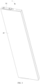
- FIG. 1 is a schematic structural diagram of a battery cell 1 according to an embodiment of the present disclosure.
- FIG. 2 is a sectional view of a battery cell according to an embodiment of the present disclosure.
- FIG. 3 is a partially enlarged schematic view at position A in FIG. 2 .
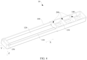
- FIG. 4 is a schematic structural diagram of a spacer according to an embodiment of the present disclosure.
- FIG. 5 is a front view of a spacer according to an embodiment of the present disclosure.
- FIG. 6 is a sectional view of a spacer according to an embodiment of the present disclosure.
- a spacer 10 for a battery cell 1 according to the embodiments of the present disclosure is described below with reference to FIG. 1 to FIG. 6 .
- the spacer 10 includes a spacer body 100 having an accommodation groove 110.
- the accommodation groove 110 has a gap 120 formed at a bottom wall of the accommodation groove 110.
- the gap 120 is in communication with the accommodation groove 110, and the gap 120 is adapted for a tab 31 of the battery cell 1 to pass through the gap, to enable the tab 31 to be partially accommodated in the accommodation groove 110.
- the spacer body 100 has a width D, and the gap 120 has a width d, where 3*d ⁇ 2*D.
- the battery cell 1 can include a cover plate assembly 20, a battery core 30, a spacer 10, and a housing 40.
- the battery core 30 can be mounted in the housing 40.
- the spacer 10 can be disposed between the cover plate assembly 20 and the battery core 30.
- the cover plate assembly 20 can be fixedly connected to the housing 40 to enable the battery core 30 and the spacer 10 to be sealingly disposed inside the housing 40. In this way, the battery core 30 can be pressed and fixed by the spacer 10 to prevent displacement of the battery core 30 due to vibration of the battery cell 1.
- the battery core 30 can be provided with the tab 31 at an end of the battery core 30.
- An end of the tab 31 can be electrically connected to positive and negative electrode plates (not shown in the figures) inside the battery core 30 by welding, and the other end of the tab 31 can be electrically connected to a pole 50 of the battery cell 1 by welding.
- the battery core 30 can be electrically connected to the pole 50.
- the battery core 30 can be electrically connected to an external circuit through the pole 50, to allow the battery cell 1 to be charged and discharged.
- the cover plate assembly 20 can include a cover plate 21 and a lower plastic 22.
- a height direction of the battery cell can be a direction denoted by Z in FIG. 2 .
- one side surface of the lower plastic 22 can be fixedly connected to a lower surface of the cover plate 21 by adhesive, etc., and the other side surface of the lower plastic 22 facing away from the cover plate 21 can abut with the spacer 10. That is, the lower plastic 22 can be abutted between the spacer 10 and the cover plate 21. In this way, the tab 31 can be separated from the cover plate 21 by the lower plastic 22 to allow an insulation between the tab 31 and the cover plate 21 to be maintained, which can effectively avoid short circuit failure of the battery cell 1 due to a contact between the tab 31 and the cover plate 21.
- the spacer body 100 can have a rectangular structure.
- a length direction of the spacer body 100 can be a direction denoted by X in FIG. 3 .
- a width direction of the spacer body 100 can be a direction denoted by Y in FIG. 3 .
- a height direction of the spacer body 100 can be a direction denoted by Z in FIG. 3 .
- the accommodation groove 110 can be integrally formed at the spacer body 100.
- a length direction, a width direction, and a depth direction of the accommodation groove 110 are respectively parallel to the length direction, the width direction, and the height direction of the spacer body 100.
- the gap 120 can be integrally formed at the bottom wall of the accommodation groove 110.
- the gap 120 can penetrate the bottom wall of the accommodation groove 110 in the depth direction of the accommodation groove 110, and can extend in the length direction of the accommodation groove 110.
- an end of the tab 31 facing away from the battery core 30 can pass through the gap 120 to be welded to the pole 50.
- the partial structure of the tab 31 between the pole 50 and the battery core 30 can be bent and accommodated in the accommodation groove 110.
- the tab 31 can be isolated and shaped by the spacer 10, allowing the partial structure of the tab 31 to be constrained inside the spacer 10. Therefore, the insulation and isolation between the tab 31 and the housing 40 can be maintained, and thus the insulation and safety of the battery cell 1 can be greatly improved.
- the width of the spacer body 100 can be labeled as D, and the width of the gap 120 can be labeled as d.
- a relationship between the width of the spacer body 100 and the width of the gap 120 can satisfy the following relational expression: 3*d ⁇ 2*D. That is, the width of the gap 120 can be smaller than or equal to 2/3 times the width of the spacer body 100. Therefore, an insulation effect of the spacer 10 on the tab 31 can be optimized to avoid the poor insulation effect of the spacer 10 due to excessive gap 120.
- the accommodation groove 110 and the gap 120 are formed at the spacer body 100, and the gap 120 is in communication with the accommodation groove 110.
- the tab 31 can be isolated and shaped by the spacer 10, to allow the partial structure of the tab 31 to be constrained inside the spacer 10, thereby maintaining insulation and isolation between the tab 31 and the housing 40 of the battery cell 1. Therefore, the insulation and safety of the battery cell 1 can be greatly improved.
- the width of the gap 120 is smaller than or equal to 2/3 times the width of the spacer body 100, the insulation effect of the spacer 10 on the tab 31 can be optimized to avoid the poor insulation effect of the spacer 10 deteriorating due to excessive gap 20.
- the spacer body 100 further has a pressure relief groove 130.
- the pressure relief groove 130 and the accommodation groove 110 are arranged in the length direction of the spacer body 100.
- the pressure relief groove 130 is adapted to discharge gas inside the battery cell 1.
- the pressure relief groove 130 and the accommodation groove 110 can be arranged adjacent to each other in the length direction of the spacer body 100.
- the pressure relief groove 130 can be integrally formed at the spacer body 100.
- a length direction, a width direction, and a depth direction of the pressure relief groove 130 are respectively parallel to the length direction, the width direction, and the height direction of the spacer body 100.
- the pressure relief groove 130 has at least one pressure relief hole 140 formed at a bottom wall of the pressure relief groove 130.
- the number of the pressure relief hole 140 can be one, two, or more, which is not specifically limited in the embodiments of the present disclosure.
- the pressure relief hole 140 can be circular, elliptical, rectangular, etc., which is not specifically limited by the present disclosure.
- the pressure relief hole 140 can penetrate the bottom wall of the pressure relief groove 130 in the depth direction of the pressure relief groove 130. In this way, when a failure occurs in the battery core 30 and a large amount of gas is generated, the pressure relief hole 140 can discharge the gas inside the battery core 30 in time, which can effectively prevent the battery core 30 from expanding, and prevent the battery cell 1 from exploding, thereby effectively reducing the safety hazards of the battery cell 1.
- the at least one pressure relief hole 140 includes a plurality of pressure relief holes 140.
- the plurality of pressure relief holes 140 are arranged at intervals in the length direction of the spacer body 100; and/or the plurality of pressure relief holes 140 are arranged at intervals in the width direction of the spacer body 100.
- the plurality of pressure relief holes 140 is provided, and the following embodiment takes six pressure relief holes 140 as an example for explanation.
- the six pressure relief holes 140 are arranged in two rows and three columns at the bottom wall of the pressure relief groove 130. That is, the six pressure relief holes 140 can be uniformly and alternately arranged in three columns in the length direction of the pressure relief groove 130, and the six pressure relief holes 140 can be uniformly and alternately arranged in two rows in the width direction of the pressure relief groove 130. In this way, an air discharge speed of the pressure relief hole 140 can be further increased, to allow the gas generated inside the battery core 30 to be rapidly discharged.
- the spacer 10 further includes a reinforcing rib 200.
- the reinforcing rib 200 is disposed between the accommodation groove 110 and the pressure relief groove 130; and/or the reinforcing rib 200 is disposed between the plurality of pressure relief holes 140.
- the reinforcing rib 200 can be integrally and fixedly connected to the spacer body 100.
- the reinforcing rib 200 can extend in the width direction of the spacer body 100. That is, a length direction of the reinforcing rib 200 can be parallel to the width direction of the spacer body 100, and a width direction of the reinforcing rib 200 can be parallel to the length direction of the spacer body 100.
- the number of the reinforcing rib 200 can be one, two, or more, which is not specifically limited by the embodiments of the present disclosure. The following embodiments take three reinforcing ribs 200 as an example for explanation.
- One reinforcing rib 200 can be disposed between the accommodation groove 110 and the pressure relief groove 130, and the other two reinforcing ribs 200 can be disposed at intervals between two adjacent columns of pressure relief holes 140.
- Such arrangement can effectively improve the strength and hardness of the spacer body 100 through the reinforcing rib 200, preventing the spacer 10 from deforming after being pressed.
- the spacer 10 can be firmly abutted between the cover plate assembly 20 and the battery core 30, to allow the spacer 10 to effectively limit the battery core 30, preventing displacement of the battery core 30 due to vibration of the battery cell 1.
- the pressure relief groove 130 has a sidewall width D1 in the length direction of the spacer body and a sidewall width D2 in the width direction of the spacer body 100, wherein D2*0.8 ⁇ D1 ⁇ D2*1.2, where D1 ⁇ 0.8 mm and D2 ⁇ 0.8 mm.
- the sidewall width of the pressure relief groove 130 in the length direction of the spacer body 100 can be labeled as D1, and the sidewall width of the pressure relief groove 130 in the width direction of the spacer body 100 can be labeled as D2.
- D1 can be greater than or equal to 0.8 mm
- D2 can be greater than or equal to 0.8 mm.
- a relationship between D1 and D2 can satisfy the following relational expression: D2*0.8 ⁇ D1 ⁇ D2*1.2, that is, D1 can be between 0.8 times of D2 and 1.2 times of D2. In this way, the spacer body 100 has better strength and hardness, and the spacer 10 is prevented from deforming under pressure.
- the reinforcing rib 200 has a width D3, where D2*0.5 ⁇ D3 ⁇ D2.
- the width of the reinforcing rib 200 can be labeled as D3, and D3 can be between 0.5 times of D2 and 1.0 times of D2. In this way, the spacer body 100 has better strength and hardness, and the spacer 10 is prevented from deforming under pressure.
- the spacer body 100 further has a mounting groove 150 formed at an end of the accommodation groove 110 facing away from the pressure relief groove 130.
- the mounting groove 150, the accommodation groove 110, and the pressure relief groove 130 can be arranged in sequence in the length direction of the spacer body 100, that is, the mounting groove 150 and the pressure relief groove 130 can be respectively disposed at two opposite ends of the accommodation groove 110.
- a length direction of the mounting groove 150 can be parallel to the width direction of the spacer body 100, and a width direction of the mounting groove 150 can be parallel to the length direction of the spacer body 100.
- a plurality of mounting holes can be formed in the mounting groove 150. Bolts (not shown in the figures) or screws (not shown in the figures) can be inserted into the mounting holes, allowing the spacer 10 to be threadedly connected to the cover plate 21 or the housing 40 of the battery cell 1.
- the spacer body 100 has a length L
- the pressure relief groove 130 has a length L1
- the mounting groove 150 has a width L2, wherein L ⁇ (L1+L2)*3, where L1 ⁇ 3 mm and L2 ⁇ 3 mm.
- the length of the spacer body 100 can be labeled as L
- the length of the pressure relief groove 130 can be labeled as L1
- the width of the mounting groove 150 can be labeled as L2.
- L1 can be greater than or equal to 3 mm
- L2 can be greater than or equal to 3 mm.
- a sum of the length of the pressure relief groove 130 and the width of the mounting groove 150 can be greater than or equal to 1/3 times of the length of the spacer body 100. In this way, the anti-vibration performance of the spacer 10 can be effectively improved.
- the spacer 10 can be prevented from pressing and damaging the battery core 30, thus effectively limiting the battery core 30 and preventing displacement of the battery core 30 due to vibration of the battery cell 1.
- the battery cell 1 includes a cover plate assembly 20, a battery core 30, and a spacer 10 disposed between the cover plate assembly 20 and the battery core 30.
- the spacer 10 is the spacer 10 for the battery cell 1 in the above embodiments. A specific structure and working principle of the spacer 10 have been explained in detail in the above embodiments, which are not repeated here.
- the battery cell 1 can include the cover plate assembly 20, the battery core 30, the spacer 10, and the housing 40.
- the battery core 30 can be mounted in the housing 40.
- the spacer 10 can be disposed between the cover plate assembly 20 and the battery core 30.
- the cover plate assembly 20 can be fixedly connected to the housing 40 to allow the battery core 30 and the spacer 10 to be sealingly disposed in the housing 40.
- the battery core 30 can be pressed and fixed by the spacer 10 to prevent displacement of the battery core 30 due to vibration of the battery cell 1.
- the battery core 30 can be provided with a tab 31 at an end of the battery core 30.
- An end of the tab 31 can be electrically connected to the positive and negative electrode plates inside the battery core 30 by welding, and the other end of the tab 31 can be electrically connected to the pole 50 of the battery cell 1 by welding.
- the battery core 30 can be electrically connected to the pole 50, and further the battery core 30 is electrically connected to an external circuit through the pole 50, to allow the battery cell 1 to be charged and discharged.
- the cover plate assembly 20 can include the cover plate 21 and the lower plastic 22.
- one side surface of the lower plastic 22 can be fixedly connected to the lower surface of the cover plate 21 by adhesive, etc., and the other side surface of the lower plastic 22 facing away from the cover plate 21 can abut with the spacer 10. That is, the lower plastic 22 can be abutted between the spacer 10 and the cover plate 21.
- the tab 31 can be separated from the cover plate 21 by the lower plastic 22 to allow the insulation between the tab 31 and the cover plate 21 to be maintained, which can effectively avoid the short circuit failure of a battery due to the contact between the tab 31 and the cover plate 21.
- a battery pack (not shown in the figures) according to the embodiments of the present disclosure includes the spacer 10 for battery cell 1 in the embodiments described above, and/or the battery cell 1 in the embodiments described above. Specific structures and working principles of the spacer 10 and the battery cell 1 have been explained in detail in the above embodiments, which are not repeated here.
- a vehicle (not shown in the figures) according to the embodiments of the present disclosure includes the spacer 10 for battery cell 1 in the embodiments described above, and/or the battery cell 1 in the embodiments described above, and/or the battery pack in the embodiments described above. Specific structures and working principles of the spacer 10, the battery cell 1, and the battery pack have been explained in detail in the above embodiments, which are not repeated here.
- first and second are only used for descriptive purposes, and cannot be understood as indicating or implying relative importance or implicitly indicating the number of the indicated technical features. Therefore, the features associated with “first” and “second” may explicitly or implicitly include at least one of the features. In the description of the present disclosure, “plurality” means at least two, unless otherwise specifically defined.
- the first feature "on” or “under” the second feature may mean that the first feature is in direct contact with the second feature, or the first and second features are in indirect contact through an intermediate.
- the first feature "above” the second feature may mean that the first feature is directly above or obliquely above the second feature, or simply mean that the level of the first feature is higher than that of the second feature.
- the first feature "below” the second feature may mean that the first feature is directly below or obliquely below the second feature, or simply mean that the level of the first feature is smaller than that of the second feature.
Landscapes
- Chemical & Material Sciences (AREA)
- Chemical Kinetics & Catalysis (AREA)
- Electrochemistry (AREA)
- General Chemical & Material Sciences (AREA)
- Gas Exhaust Devices For Batteries (AREA)
- Battery Mounting, Suspending (AREA)
- Cell Separators (AREA)
- Connection Of Batteries Or Terminals (AREA)
Abstract
Description
- This application is based on and claims priority to
Chinese Patent Application No. 202211716323.1 Chinese Patent Application No. 202223610839.6, both filed on December 29, 2022 - The present disclosure relates to the field of vehicle technologies, and more particularly, to a spacer for a battery cell, a battery cell, a battery pack, and a vehicle.
- In the related art, a battery cell can include a cover plate, a lower plastic, and a battery core. The lower plastic is connected between the cover plate and the battery core.
- To meet a welding requirement of a tab, a side edge of the lower plastic cannot be completely closed. In this way, the tab, after being bent, cannot be effectively isolated from a housing of the battery cell to allow a risk of a short circuit between the tab and the housing to be increased, causing insulation and safety of the battery cell to be poor.
- The present disclosure aims at solving at least one of the technical problems existing in the related art. To this end, an object of the present disclosure is to provide a spacer for a battery cell, which can effectively improve insulation and safety of the battery cell.
- Another object of the present disclosure is to provide a battery cell.
- A further object of the present disclosure is to provide a battery pack.
- A final object of the present disclosure is to provide a vehicle.
- The spacer for the battery cell according to the present disclosure includes a spacer body having an accommodation groove. The accommodation groove has a gap formed at a bottom wall of the accommodation groove. The gap is in communication with the accommodation groove, and the gap is adapted for a tab of the battery cell to pass through the gap to enable the tab to be partially accommodated in the accommodation groove. The spacer body has a width D, and the gap has a width d, where 3*d ≤ 2*D.
- With the spacer for the battery cell according to the embodiments of the present disclosure, the accommodation groove and the gap are formed at the spacer body, and the gap is in communication with the accommodation groove. In this way, the tab can be isolated and shaped by the spacer, to allow the partial structure of the tab to be constrained inside the spacer, thereby maintaining insulation and isolation between the tab and a housing of the battery cell. Therefore, insulation and safety of the battery cell can be greatly improved. By setting the width of the gap to be smaller than or equal to 2/3 times the width of the spacer body, an insulation effect of the spacer on the tab can be optimized to avoid poor insulation effect of the spacer due to excessive gap.
- In some examples of the present disclosure, the spacer body further has a pressure relief groove. The pressure relief groove and the accommodation groove are arranged in a length direction of the spacer body. The pressure relief groove is adapted to discharge gas inside the battery cell.
- In some examples of the present disclosure, the pressure relief groove has at least one pressure relief hole formed at a bottom wall of the pressure relief groove.
- In some examples of the present disclosure, the at least one pressure relief hole includes a plurality of pressure relief holes. The plurality of pressure relief holes are arranged at intervals in the length direction of the spacer body; and/or the plurality of pressure relief holes are arranged at intervals in a width direction of the spacer body.
- In some examples of the present disclosure, the spacer further includes a reinforcing rib. The reinforcing rib is disposed between the accommodation groove and the pressure relief groove; and/or the reinforcing rib is disposed between the plurality of pressure relief holes.
- In some examples of the present disclosure, the pressure relief groove has a sidewall width D1 in the length direction of the spacer body and a sidewall width D2 in a width direction of the spacer body, wherein D2*0.8 ≤ D1 ≤ D2*1.2, where D1 ≥ 0.8 mm and D2 ≥ 0.8 mm.
- In some examples of the present disclosure, the reinforcing rib has a width D3, where D2*0.5 ≤ D3 ≤ D2.
- In some examples of the present disclosure, the spacer body further has a mounting groove formed at an end of the accommodation groove facing away from the pressure relief groove.
- In some examples of the present disclosure, the spacer body has a length L, the pressure relief groove has a length L1, and the mounting groove has a width L2, wherein L ≤ (L1+L2)*3, where L1 ≥ 3 mm and L2 ≥ 3 mm.
- The battery cell according to the present disclosure includes a cover plate assembly, a battery core, and a spacer disposed between the cover plate assembly and the battery core. The spacer is the spacer for the battery cell as described above.
- The battery pack according to the present disclosure includes the spacer for the battery cell as described above, and/or the battery cell as described above.
- The vehicle according to the present disclosure includes the spacer for the battery cell as described above, and/or the battery cell as described above, and/or the battery pack as described above.
- Additional aspects and advantages of the present disclosure will be given at least in part in the following description, or become apparent at least in part from the following description, or can be learned from practicing of the present disclosure.
-
-
FIG. 1 is a schematic structural diagram of a battery cell according to an embodiment of the present disclosure. -
FIG. 2 is a sectional view of a battery cell according to an embodiment of the present disclosure. -
FIG. 3 is a partially enlarged schematic view at position A inFIG. 2 . -
FIG. 4 is a schematic structural diagram of a spacer according to an embodiment of the present disclosure. -
FIG. 5 is a front view of a spacer according to an embodiment of the present disclosure. -
FIG. 6 is a sectional view of a spacer according to an embodiment of the present disclosure. - Embodiments of the present disclosure will be described in detail below with reference to examples thereof as illustrated in the accompanying drawings, throughout which same or similar elements, or elements having same or similar functions, are denoted by same or similar reference numerals. The embodiments described below with reference to the drawings are illustrative only, and are intended to explain, rather than limiting, the present disclosure.
-
FIG. 1 is a schematic structural diagram of abattery cell 1 according to an embodiment of the present disclosure.FIG. 2 is a sectional view of a battery cell according to an embodiment of the present disclosure.FIG. 3 is a partially enlarged schematic view at position A inFIG. 2 .FIG. 4 is a schematic structural diagram of a spacer according to an embodiment of the present disclosure.FIG. 5 is a front view of a spacer according to an embodiment of the present disclosure.FIG. 6 is a sectional view of a spacer according to an embodiment of the present disclosure. Aspacer 10 for abattery cell 1 according to the embodiments of the present disclosure is described below with reference toFIG. 1 to FIG. 6 . Thespacer 10 includes aspacer body 100 having anaccommodation groove 110. Theaccommodation groove 110 has agap 120 formed at a bottom wall of theaccommodation groove 110. Thegap 120 is in communication with theaccommodation groove 110, and thegap 120 is adapted for atab 31 of thebattery cell 1 to pass through the gap, to enable thetab 31 to be partially accommodated in theaccommodation groove 110. Thespacer body 100 has a width D, and thegap 120 has a width d, where 3*d ≤ 2*D. - In an exemplary embodiment of the present disclosure, the
battery cell 1 can include acover plate assembly 20, abattery core 30, aspacer 10, and ahousing 40. Thebattery core 30 can be mounted in thehousing 40. Thespacer 10 can be disposed between thecover plate assembly 20 and thebattery core 30. Thecover plate assembly 20 can be fixedly connected to thehousing 40 to enable thebattery core 30 and thespacer 10 to be sealingly disposed inside thehousing 40. In this way, thebattery core 30 can be pressed and fixed by thespacer 10 to prevent displacement of thebattery core 30 due to vibration of thebattery cell 1. - Further, continuing to refer to
FIG. 3 , thebattery core 30 can be provided with thetab 31 at an end of thebattery core 30. An end of thetab 31 can be electrically connected to positive and negative electrode plates (not shown in the figures) inside thebattery core 30 by welding, and the other end of thetab 31 can be electrically connected to apole 50 of thebattery cell 1 by welding. In this way, thebattery core 30 can be electrically connected to thepole 50. Furthermore, thebattery core 30 can be electrically connected to an external circuit through thepole 50, to allow thebattery cell 1 to be charged and discharged. Thecover plate assembly 20 can include acover plate 21 and alower plastic 22. A height direction of the battery cell can be a direction denoted by Z inFIG. 2 . In the height direction of thebattery cell 1, one side surface of thelower plastic 22 can be fixedly connected to a lower surface of thecover plate 21 by adhesive, etc., and the other side surface of thelower plastic 22 facing away from thecover plate 21 can abut with thespacer 10. That is, thelower plastic 22 can be abutted between thespacer 10 and thecover plate 21. In this way, thetab 31 can be separated from thecover plate 21 by thelower plastic 22 to allow an insulation between thetab 31 and thecover plate 21 to be maintained, which can effectively avoid short circuit failure of thebattery cell 1 due to a contact between thetab 31 and thecover plate 21. - Continuing to refer to
FIG. 4 to FIG. 6 , thespacer body 100 can have a rectangular structure. A length direction of thespacer body 100 can be a direction denoted by X inFIG. 3 . A width direction of thespacer body 100 can be a direction denoted by Y inFIG. 3 . A height direction of thespacer body 100 can be a direction denoted by Z inFIG. 3 . Theaccommodation groove 110 can be integrally formed at thespacer body 100. A length direction, a width direction, and a depth direction of theaccommodation groove 110 are respectively parallel to the length direction, the width direction, and the height direction of thespacer body 100. Thegap 120 can be integrally formed at the bottom wall of theaccommodation groove 110. Thegap 120 can penetrate the bottom wall of theaccommodation groove 110 in the depth direction of theaccommodation groove 110, and can extend in the length direction of theaccommodation groove 110. As shown inFIG. 3 , an end of thetab 31 facing away from thebattery core 30 can pass through thegap 120 to be welded to thepole 50. In this case, the partial structure of thetab 31 between thepole 50 and thebattery core 30 can be bent and accommodated in theaccommodation groove 110. In this way, thetab 31 can be isolated and shaped by thespacer 10, allowing the partial structure of thetab 31 to be constrained inside thespacer 10. Therefore, the insulation and isolation between thetab 31 and thehousing 40 can be maintained, and thus the insulation and safety of thebattery cell 1 can be greatly improved. - As shown in
FIG. 5 , the width of thespacer body 100 can be labeled as D, and the width of thegap 120 can be labeled as d. A relationship between the width of thespacer body 100 and the width of thegap 120 can satisfy the following relational expression: 3*d ≤ 2*D. That is, the width of thegap 120 can be smaller than or equal to 2/3 times the width of thespacer body 100. Therefore, an insulation effect of thespacer 10 on thetab 31 can be optimized to avoid the poor insulation effect of thespacer 10 due toexcessive gap 120. - With the
spacer 10 for thebattery cell 1 according to the embodiments of the present disclosure, theaccommodation groove 110 and thegap 120 are formed at thespacer body 100, and thegap 120 is in communication with theaccommodation groove 110. In this way, thetab 31 can be isolated and shaped by thespacer 10, to allow the partial structure of thetab 31 to be constrained inside thespacer 10, thereby maintaining insulation and isolation between thetab 31 and thehousing 40 of thebattery cell 1. Therefore, the insulation and safety of thebattery cell 1 can be greatly improved. By setting the width of thegap 120 to be smaller than or equal to 2/3 times the width of thespacer body 100, the insulation effect of thespacer 10 on thetab 31 can be optimized to avoid the poor insulation effect of thespacer 10 deteriorating due toexcessive gap 20. - Continuing to refer to
FIG. 3 to FIG. 6 , according to another embodiment of the present disclosure, thespacer body 100 further has apressure relief groove 130. Thepressure relief groove 130 and theaccommodation groove 110 are arranged in the length direction of thespacer body 100. Thepressure relief groove 130 is adapted to discharge gas inside thebattery cell 1. - In an exemplary embodiment of the present disclosure, the
pressure relief groove 130 and theaccommodation groove 110 can be arranged adjacent to each other in the length direction of thespacer body 100. Thepressure relief groove 130 can be integrally formed at thespacer body 100. A length direction, a width direction, and a depth direction of thepressure relief groove 130 are respectively parallel to the length direction, the width direction, and the height direction of thespacer body 100. In this way, when a failure occurs inside thebattery core 30 and a large amount of gas is generated, thepressure relief groove 130 can discharge the gas inside thebattery core 30 in time, which can effectively prevent thebattery core 30 from expanding, and prevent thebattery cell 1 from exploding, thereby effectively reducing safety hazards of thebattery cell 1. - Continuing to refer to
FIG. 3 to FIG. 5 , according to another embodiment of the present disclosure, thepressure relief groove 130 has at least onepressure relief hole 140 formed at a bottom wall of thepressure relief groove 130. - In an exemplary embodiment of the present disclosure, the number of the
pressure relief hole 140 can be one, two, or more, which is not specifically limited in the embodiments of the present disclosure. Thepressure relief hole 140 can be circular, elliptical, rectangular, etc., which is not specifically limited by the present disclosure. Thepressure relief hole 140 can penetrate the bottom wall of thepressure relief groove 130 in the depth direction of thepressure relief groove 130. In this way, when a failure occurs in thebattery core 30 and a large amount of gas is generated, thepressure relief hole 140 can discharge the gas inside thebattery core 30 in time, which can effectively prevent thebattery core 30 from expanding, and prevent thebattery cell 1 from exploding, thereby effectively reducing the safety hazards of thebattery cell 1. - Continuing to refer to
FIG. 4 andFIG. 5 , according to another exemplary embodiment of the present disclosure, the at least onepressure relief hole 140 includes a plurality of pressure relief holes 140. The plurality ofpressure relief holes 140 are arranged at intervals in the length direction of thespacer body 100; and/or the plurality ofpressure relief holes 140 are arranged at intervals in the width direction of thespacer body 100. - In an exemplary embodiment of the present disclosure, the plurality of
pressure relief holes 140 is provided, and the following embodiment takes sixpressure relief holes 140 as an example for explanation. The sixpressure relief holes 140 are arranged in two rows and three columns at the bottom wall of thepressure relief groove 130. That is, the sixpressure relief holes 140 can be uniformly and alternately arranged in three columns in the length direction of thepressure relief groove 130, and the sixpressure relief holes 140 can be uniformly and alternately arranged in two rows in the width direction of thepressure relief groove 130. In this way, an air discharge speed of thepressure relief hole 140 can be further increased, to allow the gas generated inside thebattery core 30 to be rapidly discharged. - Continuing to refer to
FIG. 4 andFIG. 5 , according to a further embodiment of the present disclosure, thespacer 10 further includes a reinforcingrib 200. The reinforcingrib 200 is disposed between theaccommodation groove 110 and thepressure relief groove 130; and/or the reinforcingrib 200 is disposed between the plurality of pressure relief holes 140. - In an exemplary embodiment of the present disclosure, the reinforcing
rib 200 can be integrally and fixedly connected to thespacer body 100. The reinforcingrib 200 can extend in the width direction of thespacer body 100. That is, a length direction of the reinforcingrib 200 can be parallel to the width direction of thespacer body 100, and a width direction of the reinforcingrib 200 can be parallel to the length direction of thespacer body 100. The number of the reinforcingrib 200 can be one, two, or more, which is not specifically limited by the embodiments of the present disclosure. The following embodiments take three reinforcingribs 200 as an example for explanation. One reinforcingrib 200 can be disposed between theaccommodation groove 110 and thepressure relief groove 130, and the other two reinforcingribs 200 can be disposed at intervals between two adjacent columns of pressure relief holes 140. Such arrangement can effectively improve the strength and hardness of thespacer body 100 through the reinforcingrib 200, preventing thespacer 10 from deforming after being pressed. In this way, thespacer 10 can be firmly abutted between thecover plate assembly 20 and thebattery core 30, to allow thespacer 10 to effectively limit thebattery core 30, preventing displacement of thebattery core 30 due to vibration of thebattery cell 1. - Continuing to refer to
FIG. 5 , in another exemplary embodiment of the present disclosure, thepressure relief groove 130 has a sidewall width D1 in the length direction of the spacer body and a sidewall width D2 in the width direction of thespacer body 100, wherein D2*0.8 ≤ D1 ≤ D2*1.2, where D1 ≥ 0.8 mm and D2 ≥ 0.8 mm. - In an exemplary embodiment of the present disclosure, as shown in
FIG. 5 , the sidewall width of thepressure relief groove 130 in the length direction of thespacer body 100 can be labeled as D1, and the sidewall width of thepressure relief groove 130 in the width direction of thespacer body 100 can be labeled as D2. D1 can be greater than or equal to 0.8 mm, and D2 can be greater than or equal to 0.8 mm. A relationship between D1 and D2 can satisfy the following relational expression: D2*0.8 ≤ D1 ≤ D2*1.2, that is, D1 can be between 0.8 times of D2 and 1.2 times of D2. In this way, thespacer body 100 has better strength and hardness, and thespacer 10 is prevented from deforming under pressure. - Continuing to refer to
FIG. 5 , in some examples of the present disclosure, the reinforcingrib 200 has a width D3, where D2*0.5 ≤ D3 ≤ D2. - In an exemplary embodiment of the present disclosure, the width of the reinforcing
rib 200 can be labeled as D3, and D3 can be between 0.5 times of D2 and 1.0 times of D2. In this way, thespacer body 100 has better strength and hardness, and thespacer 10 is prevented from deforming under pressure. - Continuing to refer to
FIG. 4 andFIG. 5 , in some embodiments of the present disclosure, thespacer body 100 further has a mountinggroove 150 formed at an end of theaccommodation groove 110 facing away from thepressure relief groove 130. - In an exemplary embodiment of the present disclosure, the mounting
groove 150, theaccommodation groove 110, and thepressure relief groove 130 can be arranged in sequence in the length direction of thespacer body 100, that is, the mountinggroove 150 and thepressure relief groove 130 can be respectively disposed at two opposite ends of theaccommodation groove 110. A length direction of the mountinggroove 150 can be parallel to the width direction of thespacer body 100, and a width direction of the mountinggroove 150 can be parallel to the length direction of thespacer body 100. A plurality of mounting holes (not shown in the figures) can be formed in the mountinggroove 150. Bolts (not shown in the figures) or screws (not shown in the figures) can be inserted into the mounting holes, allowing thespacer 10 to be threadedly connected to thecover plate 21 or thehousing 40 of thebattery cell 1. - Continuing to refer to
FIG. 5 , in some possible implementations of the present disclosure, thespacer body 100 has a length L, thepressure relief groove 130 has a length L1, and the mountinggroove 150 has a width L2, wherein L ≤ (L1+L2)*3, where L1 ≥ 3 mm and L2 ≥ 3 mm. - In an exemplary embodiment of the present disclosure, the length of the
spacer body 100 can be labeled as L, the length of thepressure relief groove 130 can be labeled as L1, and the width of the mountinggroove 150 can be labeled as L2. L1 can be greater than or equal to 3 mm, and L2 can be greater than or equal to 3 mm. A sum of the length of thepressure relief groove 130 and the width of the mountinggroove 150 can be greater than or equal to 1/3 times of the length of thespacer body 100. In this way, the anti-vibration performance of thespacer 10 can be effectively improved. In this case, thespacer 10 can be prevented from pressing and damaging thebattery core 30, thus effectively limiting thebattery core 30 and preventing displacement of thebattery core 30 due to vibration of thebattery cell 1. - Continuing to refer to
FIG. 1 to FIG. 3 , thebattery cell 1 according to the embodiments of the present disclosure includes acover plate assembly 20, abattery core 30, and aspacer 10 disposed between thecover plate assembly 20 and thebattery core 30. Thespacer 10 is thespacer 10 for thebattery cell 1 in the above embodiments. A specific structure and working principle of thespacer 10 have been explained in detail in the above embodiments, which are not repeated here. - In an exemplary embodiment of the present disclosure, the
battery cell 1 can include thecover plate assembly 20, thebattery core 30, thespacer 10, and thehousing 40. Thebattery core 30 can be mounted in thehousing 40. Thespacer 10 can be disposed between thecover plate assembly 20 and thebattery core 30. Thecover plate assembly 20 can be fixedly connected to thehousing 40 to allow thebattery core 30 and thespacer 10 to be sealingly disposed in thehousing 40. In this way, thebattery core 30 can be pressed and fixed by thespacer 10 to prevent displacement of thebattery core 30 due to vibration of thebattery cell 1. Further, thebattery core 30 can be provided with atab 31 at an end of thebattery core 30. An end of thetab 31 can be electrically connected to the positive and negative electrode plates inside thebattery core 30 by welding, and the other end of thetab 31 can be electrically connected to thepole 50 of thebattery cell 1 by welding. In this way, thebattery core 30 can be electrically connected to thepole 50, and further thebattery core 30 is electrically connected to an external circuit through thepole 50, to allow thebattery cell 1 to be charged and discharged. - The
cover plate assembly 20 can include thecover plate 21 and thelower plastic 22. In the height direction of thebattery cell 1, one side surface of thelower plastic 22 can be fixedly connected to the lower surface of thecover plate 21 by adhesive, etc., and the other side surface of thelower plastic 22 facing away from thecover plate 21 can abut with thespacer 10. That is, thelower plastic 22 can be abutted between thespacer 10 and thecover plate 21. In this way, thetab 31 can be separated from thecover plate 21 by thelower plastic 22 to allow the insulation between thetab 31 and thecover plate 21 to be maintained, which can effectively avoid the short circuit failure of a battery due to the contact between thetab 31 and thecover plate 21. - A battery pack (not shown in the figures) according to the embodiments of the present disclosure includes the
spacer 10 forbattery cell 1 in the embodiments described above, and/or thebattery cell 1 in the embodiments described above. Specific structures and working principles of thespacer 10 and thebattery cell 1 have been explained in detail in the above embodiments, which are not repeated here. - A vehicle (not shown in the figures) according to the embodiments of the present disclosure includes the
spacer 10 forbattery cell 1 in the embodiments described above, and/or thebattery cell 1 in the embodiments described above, and/or the battery pack in the embodiments described above. Specific structures and working principles of thespacer 10, thebattery cell 1, and the battery pack have been explained in detail in the above embodiments, which are not repeated here. - Other components of the
spacer 10 for thebattery cell 1 according to the embodiments of the present disclosure, such as a positive electrode plate, a negative electrode plate, thetab 31, thepole 50, thehousing 40, and the like, as well as operations thereof, are known to those skilled in the art, which will not be described in detail herein. - In the description of the present disclosure, it should be understood that the orientation or position relationship indicated by the terms such as "center", "longitudinal", "transverse", "length", "width", "thickness", "upper", "lower", "front", "rear", "left", "right", "vertical", "horizontal", "top", "bottom", "inner", "outer", "clockwise", "counterclockwise", "axial", "radial", and "circumferential" should be construed to refer to the orientation or the position as shown in the drawings, and is only for the convenience of describing the present disclosure and simplifying the description, rather than indicating or implying that the pointed apparatus or element must have a specific orientation, or be constructed and operated in a specific orientation, and therefore cannot be understood as a limitation of the present disclosure.
- In addition, terms "first" and "second" are only used for descriptive purposes, and cannot be understood as indicating or implying relative importance or implicitly indicating the number of the indicated technical features. Therefore, the features associated with "first" and "second" may explicitly or implicitly include at least one of the features. In the description of the present disclosure, "plurality" means at least two, unless otherwise specifically defined.
- In the present disclosure, unless otherwise clearly specified and limited, terms such as "install", "connect", "connect to", "fix" and the like should be understood in a broad sense. For example, it may be a fixed connection or a detachable connection or connection as one piece; mechanical connection or electrical connection; direct connection or indirect connection through an intermediate; internal communication of two components or the interaction relationship between two components, unless otherwise clearly limited. For those skilled in the art, the specific meaning of the above-mentioned terms in the present disclosure can be understood according to specific circumstances.
- In the present disclosure, unless expressly stipulated and defined otherwise, the first feature "on" or "under" the second feature may mean that the first feature is in direct contact with the second feature, or the first and second features are in indirect contact through an intermediate. Moreover, the first feature "above" the second feature may mean that the first feature is directly above or obliquely above the second feature, or simply mean that the level of the first feature is higher than that of the second feature. The first feature "below" the second feature may mean that the first feature is directly below or obliquely below the second feature, or simply mean that the level of the first feature is smaller than that of the second feature.
- In the description of this specification, description with reference to the terms "an embodiment", "some embodiments", "examples" "specific examples", or "some examples" etc., mean that specific features, structure, materials or characteristics described in conjunction with the embodiment or example are included in at least one embodiment or example of the present disclosure. In this specification, the schematic representations of the above terms do not necessarily refer to the same embodiment or example. Moreover, the described specific features, structures, materials or characteristics may be combined in any one or more embodiments or examples in a suitable manner. Furthermore, different embodiments or examples and features of different embodiments or examples described in this specification may be combined and combined by one skilled in the art without contradiction.
- Although embodiments of the present disclosure have been shown and described above, it should be understood that the above embodiments are merely exemplary, and cannot be construed as limitations of the present disclosure. For those skilled in the art, changes, alternatives, and modifications can be made to the above embodiments without departing from the scope of the present disclosure.
Claims (12)
- A spacer for a battery cell, comprising:a spacer body having an accommodation groove, the accommodation groove having a gap formed at a bottom wall of the accommodation groove, the gap being in communication with the accommodation groove, and the gap being adapted for a tab of the battery cell to pass through the gap to enable the tab to be partially accommodated in the accommodation groove,wherein the spacer body has a width D, and the gap has a width d, where 3*d ≤ 2*D.
- The spacer for the battery cell according to claim 1, wherein the spacer body further has a pressure relief groove, the pressure relief groove and the accommodation groove being arranged in a length direction of the spacer body, and the pressure relief groove being adapted to discharge gas inside the battery cell.
- The spacer for the battery cell according to claim 2, wherein the pressure relief groove has at least one pressure relief hole formed at a bottom wall of the pressure relief groove.
- The spacer for the battery cell according to claim 3, wherein the at least one pressure relief hole comprises a plurality of pressure relief holes, wherein:the plurality of pressure relief holes are arranged at intervals in the length direction of the spacer body; and/orthe plurality of pressure relief holes are arranged at intervals in a width direction of the spacer body.
- The spacer for the battery cell according to claim 4, further comprising a reinforcing rib, wherein:the reinforcing rib is disposed between the accommodation groove and the pressure relief groove; and/orthe reinforcing rib is disposed between the plurality of pressure relief holes.
- The spacer for the battery cell according to any one of claims 2 to 5, wherein the pressure relief groove has a sidewall width D1 in the length direction of the spacer body and a sidewall width D2 in a width direction of the spacer body, wherein D2*0.8 ≤ D1 ≤ D2*1.2, where D1 ≥ 0.8 mm and D2 ≥ 0.8 mm.
- The spacer for the battery cell according to claim 5, wherein the reinforcing rib has a width D3, where D2*0.5 ≤ D3 ≤ D2.
- The spacer for the battery cell according to any one of claims 2 to 7, wherein the spacer body further has a mounting groove, the mounting groove being formed at an end of the accommodation groove facing away from the pressure relief groove.
- The spacer for the battery cell according to claim 8, wherein:the spacer body has a length L;the pressure relief groove has a length L1; andthe mounting groove has a width L2, wherein L ≤ (L1+L2)*3, where L1 ≥ 3 mm and L2 ≥ 3 mm.
- A battery cell, comprising:a cover plate assembly;a battery core; andthe spacer for the battery cell according to any one of claims 1 to 9, the spacer being disposed between the cover plate assembly and the battery core.
- A battery pack, comprising:the spacer for the battery cell according to any one of claims 1 to 9; and/orthe battery cell according to claim 10.
- A vehicle, comprising:the spacer for the battery cell according to any one of claims 1 to 9; and/orthe battery cell according to claim 10; and/orthe battery pack according to claim 11.
Applications Claiming Priority (3)
| Application Number | Priority Date | Filing Date | Title |
|---|---|---|---|
| CN202223610839.6U CN218939851U (en) | 2022-12-29 | 2022-12-29 | Spacers for battery cells, battery cells, battery packs and vehicles |
| CN202211716323.1A CN115954587A (en) | 2022-12-29 | 2022-12-29 | Spacers for battery cells, battery cells, battery packs and vehicles |
| PCT/CN2023/129704 WO2024139725A1 (en) | 2022-12-29 | 2023-11-03 | Spacer for battery cell, battery cell, battery pack, and vehicle |
Publications (2)
| Publication Number | Publication Date |
|---|---|
| EP4535519A1 true EP4535519A1 (en) | 2025-04-09 |
| EP4535519A4 EP4535519A4 (en) | 2026-05-20 |
Family
ID=91716360
Family Applications (1)
| Application Number | Title | Priority Date | Filing Date |
|---|---|---|---|
| EP23909658.9A Pending EP4535519A4 (en) | 2022-12-29 | 2023-11-03 | Spacer for battery cell, battery cell, battery pack and vehicle |
Country Status (4)
| Country | Link |
|---|---|
| US (1) | US20250210813A1 (en) |
| EP (1) | EP4535519A4 (en) |
| JP (1) | JP2025526448A (en) |
| WO (1) | WO2024139725A1 (en) |
Family Cites Families (9)
| Publication number | Priority date | Publication date | Assignee | Title |
|---|---|---|---|---|
| CN204927397U (en) * | 2015-07-29 | 2015-12-30 | 东莞市伊斯诺电池有限公司 | Aluminum -shell battery and spacer ring thereof |
| CN206180012U (en) * | 2016-11-21 | 2017-05-17 | 惠州市元大电子科技有限公司 | Lithium ion battery structure |
| CN210296418U (en) * | 2019-06-19 | 2020-04-10 | 天能电池集团股份有限公司 | Protective sheet for storage battery |
| CN211350812U (en) * | 2019-12-31 | 2020-08-25 | 惠州比亚迪电池有限公司 | Spacer assembly and battery |
| CN217507574U (en) * | 2021-12-28 | 2022-09-27 | 荣盛盟固利新能源科技股份有限公司 | Battery spacer ring assembly and battery |
| CN217086819U (en) * | 2022-04-12 | 2022-07-29 | 极氪汽车(宁波杭州湾新区)有限公司 | Battery space ring, electric core assembly and battery |
| CN218939851U (en) * | 2022-12-29 | 2023-04-28 | 浙江极氪智能科技有限公司 | Spacers for battery cells, battery cells, battery packs and vehicles |
| CN115954587A (en) * | 2022-12-29 | 2023-04-11 | 浙江极氪智能科技有限公司 | Spacers for battery cells, battery cells, battery packs and vehicles |
| CN116505152A (en) * | 2023-05-18 | 2023-07-28 | 广汽埃安新能源汽车股份有限公司 | End cover assembly and battery cell |
-
2023
- 2023-11-03 WO PCT/CN2023/129704 patent/WO2024139725A1/en not_active Ceased
- 2023-11-03 JP JP2025504804A patent/JP2025526448A/en active Pending
- 2023-11-03 EP EP23909658.9A patent/EP4535519A4/en active Pending
-
2025
- 2025-03-11 US US19/076,951 patent/US20250210813A1/en active Pending
Also Published As
| Publication number | Publication date |
|---|---|
| EP4535519A4 (en) | 2026-05-20 |
| US20250210813A1 (en) | 2025-06-26 |
| WO2024139725A1 (en) | 2024-07-04 |
| JP2025526448A (en) | 2025-08-13 |
Similar Documents
| Publication | Publication Date | Title |
|---|---|---|
| KR101201744B1 (en) | Rechargeable battery | |
| EP4087024A1 (en) | Battery, battery pack and electric vehicle | |
| KR101015834B1 (en) | Battery module | |
| KR100949333B1 (en) | Battery module | |
| KR101191659B1 (en) | Battery module | |
| EP4084203A1 (en) | Battery, battery module, battery pack, and electric vehicle | |
| WO2020207230A1 (en) | Battery module | |
| US20240356119A1 (en) | Cylindrical Battery, Electric Apparatus and Manufacturing Method for Cylindrical Battery | |
| CN218939851U (en) | Spacers for battery cells, battery cells, battery packs and vehicles | |
| CN115954587A (en) | Spacers for battery cells, battery cells, battery packs and vehicles | |
| CN219979669U (en) | A battery case and battery | |
| EP3246930A1 (en) | Electric energy storage device having improved terminal structure | |
| KR102749680B1 (en) | Absence of adapter, battery cell, battery, electrical device and method for manufacturing battery cell and manufacturing equipment | |
| US20250210813A1 (en) | Spacer for battery cell, battery cell, battery pack, and vehicle | |
| CN217114627U (en) | Battery and electric device | |
| KR20090081174A (en) | Secondary battery | |
| CN217788665U (en) | Battery pack and vehicle | |
| EP4510374A1 (en) | Battery cell, battery, electric device, and battery cell manufacturing method | |
| CN116387721A (en) | Batteries and Consumers | |
| CN223898569U (en) | Battery cells, batteries and electrical devices | |
| KR102861336B1 (en) | Battery cells, batteries, electrical devices and methods for manufacturing battery cells | |
| CN224153396U (en) | Battery and power utilization device | |
| CN221861772U (en) | Battery case and battery | |
| CN222168546U (en) | Battery cells, batteries and electrical devices | |
| CN223052236U (en) | Battery monomer, battery and power consumption device |
Legal Events
| Date | Code | Title | Description |
|---|---|---|---|
| STAA | Information on the status of an ep patent application or granted ep patent |
Free format text: STATUS: THE INTERNATIONAL PUBLICATION HAS BEEN MADE |
|
| PUAI | Public reference made under article 153(3) epc to a published international application that has entered the european phase |
Free format text: ORIGINAL CODE: 0009012 |
|
| STAA | Information on the status of an ep patent application or granted ep patent |
Free format text: STATUS: REQUEST FOR EXAMINATION WAS MADE |
|
| 17P | Request for examination filed |
Effective date: 20241230 |
|
| AK | Designated contracting states |
Kind code of ref document: A1 Designated state(s): AL AT BE BG CH CY CZ DE DK EE ES FI FR GB GR HR HU IE IS IT LI LT LU LV MC ME MK MT NL NO PL PT RO RS SE SI SK SM TR |
|
| DAV | Request for validation of the european patent (deleted) | ||
| DAX | Request for extension of the european patent (deleted) | ||
| REG | Reference to a national code |
Ref country code: DE Ref legal event code: R079 Free format text: PREVIOUS MAIN CLASS: H01M0050103000 Ipc: H01M0050176000 |