EP4535511A1 - Liquid cooling plate, liquid cooling system and battery module - Google Patents
Liquid cooling plate, liquid cooling system and battery module Download PDFInfo
- Publication number
- EP4535511A1 EP4535511A1 EP24827785.7A EP24827785A EP4535511A1 EP 4535511 A1 EP4535511 A1 EP 4535511A1 EP 24827785 A EP24827785 A EP 24827785A EP 4535511 A1 EP4535511 A1 EP 4535511A1
- Authority
- EP
- European Patent Office
- Prior art keywords
- liquid
- liquid cooling
- cooling plate
- collector
- liquid outlet
- Prior art date
- Legal status (The legal status is an assumption and is not a legal conclusion. Google has not performed a legal analysis and makes no representation as to the accuracy of the status listed.)
- Pending
Links
Images


Classifications
-
- F—MECHANICAL ENGINEERING; LIGHTING; HEATING; WEAPONS; BLASTING
- F28—HEAT EXCHANGE IN GENERAL
- F28F—DETAILS OF HEAT-EXCHANGE AND HEAT-TRANSFER APPARATUS, OF GENERAL APPLICATION
- F28F1/00—Tubular elements; Assemblies of tubular elements
- F28F1/10—Tubular elements and assemblies thereof with means for increasing heat-transfer area, e.g. with fins, with projections, with recesses
- F28F1/40—Tubular elements and assemblies thereof with means for increasing heat-transfer area, e.g. with fins, with projections, with recesses the means being only inside the tubular element
-
- F—MECHANICAL ENGINEERING; LIGHTING; HEATING; WEAPONS; BLASTING
- F28—HEAT EXCHANGE IN GENERAL
- F28D—HEAT-EXCHANGE APPARATUS, NOT PROVIDED FOR IN ANOTHER SUBCLASS, IN WHICH THE HEAT-EXCHANGE MEDIA DO NOT COME INTO DIRECT CONTACT
- F28D1/00—Heat-exchange apparatus having stationary conduit assemblies for one heat-exchange medium only, the media being in contact with different sides of the conduit wall, in which the other heat-exchange medium is a large body of fluid, e.g. domestic or motor car radiators
- F28D1/02—Heat-exchange apparatus having stationary conduit assemblies for one heat-exchange medium only, the media being in contact with different sides of the conduit wall, in which the other heat-exchange medium is a large body of fluid, e.g. domestic or motor car radiators with heat-exchange conduits immersed in the body of fluid
- F28D1/04—Heat-exchange apparatus having stationary conduit assemblies for one heat-exchange medium only, the media being in contact with different sides of the conduit wall, in which the other heat-exchange medium is a large body of fluid, e.g. domestic or motor car radiators with heat-exchange conduits immersed in the body of fluid with tubular conduits
- F28D1/053—Heat-exchange apparatus having stationary conduit assemblies for one heat-exchange medium only, the media being in contact with different sides of the conduit wall, in which the other heat-exchange medium is a large body of fluid, e.g. domestic or motor car radiators with heat-exchange conduits immersed in the body of fluid with tubular conduits the conduits being straight
- F28D1/0535—Heat-exchange apparatus having stationary conduit assemblies for one heat-exchange medium only, the media being in contact with different sides of the conduit wall, in which the other heat-exchange medium is a large body of fluid, e.g. domestic or motor car radiators with heat-exchange conduits immersed in the body of fluid with tubular conduits the conduits being straight the conduits having a non-circular cross-section
- F28D1/05358—Assemblies of conduits connected side by side or with individual headers, e.g. section type radiators
-
- F—MECHANICAL ENGINEERING; LIGHTING; HEATING; WEAPONS; BLASTING
- F28—HEAT EXCHANGE IN GENERAL
- F28F—DETAILS OF HEAT-EXCHANGE AND HEAT-TRANSFER APPARATUS, OF GENERAL APPLICATION
- F28F1/00—Tubular elements; Assemblies of tubular elements
- F28F1/006—Tubular elements; Assemblies of tubular elements with variable shape, e.g. with modified tube ends, with different geometrical features
-
- F—MECHANICAL ENGINEERING; LIGHTING; HEATING; WEAPONS; BLASTING
- F28—HEAT EXCHANGE IN GENERAL
- F28F—DETAILS OF HEAT-EXCHANGE AND HEAT-TRANSFER APPARATUS, OF GENERAL APPLICATION
- F28F1/00—Tubular elements; Assemblies of tubular elements
- F28F1/02—Tubular elements of cross-section which is non-circular
- F28F1/022—Tubular elements of cross-section which is non-circular with multiple channels
-
- F—MECHANICAL ENGINEERING; LIGHTING; HEATING; WEAPONS; BLASTING
- F28—HEAT EXCHANGE IN GENERAL
- F28F—DETAILS OF HEAT-EXCHANGE AND HEAT-TRANSFER APPARATUS, OF GENERAL APPLICATION
- F28F1/00—Tubular elements; Assemblies of tubular elements
- F28F1/02—Tubular elements of cross-section which is non-circular
- F28F1/025—Tubular elements of cross-section which is non-circular with variable shape, e.g. with modified tube ends, with different geometrical features
-
- H—ELECTRICITY
- H01—ELECTRIC ELEMENTS
- H01M—PROCESSES OR MEANS, e.g. BATTERIES, FOR THE DIRECT CONVERSION OF CHEMICAL ENERGY INTO ELECTRICAL ENERGY
- H01M10/00—Secondary cells; Manufacture thereof
- H01M10/60—Heating or cooling; Temperature control
- H01M10/61—Types of temperature control
- H01M10/613—Cooling or keeping cold
-
- H—ELECTRICITY
- H01—ELECTRIC ELEMENTS
- H01M—PROCESSES OR MEANS, e.g. BATTERIES, FOR THE DIRECT CONVERSION OF CHEMICAL ENERGY INTO ELECTRICAL ENERGY
- H01M10/00—Secondary cells; Manufacture thereof
- H01M10/60—Heating or cooling; Temperature control
- H01M10/64—Heating or cooling; Temperature control characterised by the shape of the cells
- H01M10/643—Cylindrical cells
-
- H—ELECTRICITY
- H01—ELECTRIC ELEMENTS
- H01M—PROCESSES OR MEANS, e.g. BATTERIES, FOR THE DIRECT CONVERSION OF CHEMICAL ENERGY INTO ELECTRICAL ENERGY
- H01M10/00—Secondary cells; Manufacture thereof
- H01M10/60—Heating or cooling; Temperature control
- H01M10/65—Means for temperature control structurally associated with the cells
- H01M10/655—Solid structures for heat exchange or heat conduction
- H01M10/6554—Rods or plates
-
- H—ELECTRICITY
- H01—ELECTRIC ELEMENTS
- H01M—PROCESSES OR MEANS, e.g. BATTERIES, FOR THE DIRECT CONVERSION OF CHEMICAL ENERGY INTO ELECTRICAL ENERGY
- H01M10/00—Secondary cells; Manufacture thereof
- H01M10/60—Heating or cooling; Temperature control
- H01M10/65—Means for temperature control structurally associated with the cells
- H01M10/655—Solid structures for heat exchange or heat conduction
- H01M10/6554—Rods or plates
- H01M10/6555—Rods or plates arranged between the cells
-
- H—ELECTRICITY
- H01—ELECTRIC ELEMENTS
- H01M—PROCESSES OR MEANS, e.g. BATTERIES, FOR THE DIRECT CONVERSION OF CHEMICAL ENERGY INTO ELECTRICAL ENERGY
- H01M10/00—Secondary cells; Manufacture thereof
- H01M10/60—Heating or cooling; Temperature control
- H01M10/65—Means for temperature control structurally associated with the cells
- H01M10/655—Solid structures for heat exchange or heat conduction
- H01M10/6556—Solid parts with flow channel passages or pipes for heat exchange
- H01M10/6557—Solid parts with flow channel passages or pipes for heat exchange arranged between the cells
-
- H—ELECTRICITY
- H01—ELECTRIC ELEMENTS
- H01M—PROCESSES OR MEANS, e.g. BATTERIES, FOR THE DIRECT CONVERSION OF CHEMICAL ENERGY INTO ELECTRICAL ENERGY
- H01M10/00—Secondary cells; Manufacture thereof
- H01M10/60—Heating or cooling; Temperature control
- H01M10/65—Means for temperature control structurally associated with the cells
- H01M10/656—Means for temperature control structurally associated with the cells characterised by the type of heat-exchange fluid
- H01M10/6567—Liquids
- H01M10/6568—Liquids characterised by flow circuits, e.g. loops, located externally to the cells or cell casings
-
- H—ELECTRICITY
- H01—ELECTRIC ELEMENTS
- H01M—PROCESSES OR MEANS, e.g. BATTERIES, FOR THE DIRECT CONVERSION OF CHEMICAL ENERGY INTO ELECTRICAL ENERGY
- H01M50/00—Constructional details or processes of manufacture of the non-active parts of electrochemical cells other than fuel cells, e.g. hybrid cells
- H01M50/20—Mountings; Secondary casings or frames; Racks, modules or packs; Suspension devices; Shock absorbers; Transport or carrying devices; Holders
- H01M50/204—Racks, modules or packs for multiple batteries or multiple cells
- H01M50/207—Racks, modules or packs for multiple batteries or multiple cells characterised by their shape
- H01M50/213—Racks, modules or packs for multiple batteries or multiple cells characterised by their shape adapted for cells having curved cross-section, e.g. round or elliptic
-
- Y—GENERAL TAGGING OF NEW TECHNOLOGICAL DEVELOPMENTS; GENERAL TAGGING OF CROSS-SECTIONAL TECHNOLOGIES SPANNING OVER SEVERAL SECTIONS OF THE IPC; TECHNICAL SUBJECTS COVERED BY FORMER USPC CROSS-REFERENCE ART COLLECTIONS [XRACs] AND DIGESTS
- Y02—TECHNOLOGIES OR APPLICATIONS FOR MITIGATION OR ADAPTATION AGAINST CLIMATE CHANGE
- Y02E—REDUCTION OF GREENHOUSE GAS [GHG] EMISSIONS, RELATED TO ENERGY GENERATION, TRANSMISSION OR DISTRIBUTION
- Y02E60/00—Enabling technologies; Technologies with a potential or indirect contribution to GHG emissions mitigation
- Y02E60/10—Energy storage using batteries
Definitions
- the present application relates to the field of battery technologies, and in particular, to a liquid cooling plate, a liquid cooling system, and a battery module.
- the snake-shaped liquid cooling plate is in contact with the side surface of the cell for heat exchange, has the advantages of high heat dissipation efficiency, large heat exchange area, small pressure drop, good thermal insulation effect and high structural strength, and becomes the mainstream of the liquid cooling plate for a power battery.
- a flow channel in a serpentine liquid cooling plate is mostly formed by a plurality of square regular cavities.
- a cooling liquid is distributed into the plurality of cavities by a water inlet collector, flows in the flow channel and forms convection heat exchange with a cell, and finally converges into the water outlet collector and flows out from a liquid outlet.
- the flow disturbance member has a single helical structure and extends along the first direction.
- the present application further provides a liquid cooling system, including a liquid collector and a liquid cooling plate as described above, wherein a flow channel is provided inside the liquid cooling plate, and the flow channel has a liquid inlet end and a liquid outlet end; the collector includes a liquid inlet collector and a liquid outlet collector, the liquid inlet collector is communicated with the liquid inlet end, and the liquid outlet collector is communicated with the liquid outlet end.
- the present application further provides a battery module, including the liquid cooling system above.
- the present application provides a liquid cooling plate.
- a flow disturbance member is a single helical structure, and a helical extension direction of the single helical structure is the same as an extension direction of the flow channel, a relatively strong turbulent flow is formed by the single helical structure after cooling liquid enters the flow channel, thereby increasing the heat exchange efficiency of a liquid cooling pipe.
- the present application further provides a liquid cooling system.
- a liquid inlet end, a liquid outlet end, a liquid inlet collector, and a liquid outlet collector of the liquid cooling plate are disposed at the same end of the liquid cooling plate, so that on one hand, it is convenient for the concentration and rapid connection of the liquid inlet end and the liquid inlet collector, as well as that of the liquid outlet end and the liquid outlet collector.
- the present application further provides a battery module.
- the collector and the connection pipelines are disposed on the same side of the liquid cooling plate, so that space occupied by the liquid-cooling system in the battery module is saved.
- connection should be understood broadly, for example, fixed connections, detachable connections, or integral connections; and can also be mechanical or electrical connections; can also be direct connections or indirect connections via intervening structures; can also be inner communications of two elements or interaction relationships between two elements.
- connection should be understood broadly, for example, fixed connections, detachable connections, or integral connections; and can also be mechanical or electrical connections; can also be direct connections or indirect connections via intervening structures; can also be inner communications of two elements or interaction relationships between two elements.
- orientation or position relationships of terms such as 'up', 'down', 'left', 'right', 'front', and 'rear' are based on orientation or position relationships shown in the drawings, which are used for ease of description and simplifying operations, but do not indicate or imply that a device or element referred to must have a specific orientation, or be constructed and operated in a specific orientation, and therefore cannot be construed as limitations to this application.
- first and “second” are used for distinguishing in terms of description, and do not have a special meaning.
- embodiments of the present application provide a liquid cooling plate 10, where the liquid cooling plate 10 includes a liquid cooling plate body 100 and a flow disturbance member 200.
- the liquid cooling plate body 100 extends along a first direction, a side face 101 of the liquid cooling plate body 100 is a curved face or a flat face, and the side face of the liquid cooling plate body 100 conforms with a side wall of a cell 20.
- a plurality of flow channels 110 extending along a first direction are provided inside the liquid cooling plate body 100, and the flow disturbance member 200 is provided in the flow channel 110.
- the flow disturbance member 200 has a single helical structure and extends in the first direction.
- the liquid cooling plate 10 is a plate-shaped structure having a certain thickness and disposed between the cells 20, and contacts a side wall of the cell 20, so as to cool the cell 20.
- the side surface 101 is a curved surface
- the liquid cooling plate 10 is a curved surface liquid cooling plate.
- the side surface 101 of the liquid cooling plate body 100 is a wavy concave-convex curved surface extending along a first direction
- the concave-convex curved surface includes a concave portion and a convex portion
- the curvature of the concave portion and the convex portion matches the diameter of the cell 20.
- the concave portion near the side surface 101 of one side of the cell 20 is attached to the side wall of the cylindrical cell and the protruding portion is located between adjacent cells 20, which increase the contact area between the side surface 101 of the liquid cooling plate body and the side wall of the cell 20.
- the increase of the contact area facilitates heat conduction of the cell 20, so that a heat conduction rate thereof is greater and the temperature equalization performance is better, thereby improving heat exchange efficiency of the liquid cooling plate 10.
- the side surface 101 is a plane
- the liquid cooling plate 10 is a planar liquid cooling plate.
- the planar side surface 101 is attached to the side wall of the planar cell, so as to perform heat exchange, thereby cooling the cells 20.
- the flow channel 110 is a hollow channel arranged inside the liquid cooling plate 10, the channel extends in a first direction (i.e. an X direction in the figure).
- the flow channel 110 includes a liquid inlet opening and a liquid outlet opening, the cooling liquid enters the flow channel from the liquid inlet opening, and is output from the liquid outlet opening to the liquid cooling plate 10.
- the cooling liquid flowing through the flow channel 110 exchanges heat with the cell 20, so as to cool the cell 20.
- the flow disturbance member 200 has a long strip shape and a single helical structure, and the extending direction of the flow disturbance member 200 is consistent with the extending direction of the flow channel 110.
- the flow disturbance member 200 is disposed between the inner wall of the flow channel 110 and the inner wall of the flow channel 110 to form a single helical channel, and the cooling liquid flows in the single helical channel.
- a shape of the flow disturbance member 200 is consistent with a shape of the flow channel 110.
- the flow disturbance member 200 is arranged in a curved shape along the first direction, so that on one hand, the fitting degree with the shape of the flow channel is improved, and on the other hand, the flow disturbance member effect is enhanced, and the liquid cooling efficiency of the liquid cooling plate 10 is improved.
- the flow disturbance member 200 is arranged linearly along the first direction.
- a flow disturbance member with a single helical structure is additionally provided in the flow channel of the liquid cooling plate 10, so as to enhance the flow disturbance effect on the cooling liquid flowing through the flow channel, increase the contact area between the cooling liquid and the flow disturbance member, and enhance the heat exchange efficiency of the cooling liquid.
- the flow disturbance member 200 is formed by helical blades, and the flow disturbance member 200 is configured as a blade-type helical structure, so that the contact area between the cooling liquid and the blade surface is increased, thereby enhancing the flow disturbance member effect and the heat exchange efficiency.
- a through hole 220 is provided on the helical blade 210 of the flow disturbance member 200, the through hole 220 penetrates through the helical blades 210, and a part of the cooling liquid flows through the through hole 220, which can effectively reduce the flow resistance of the cooling liquid in the flow channel 110.
- the through holes 220 can also enhance the effect of turbulence and improve the heat exchange efficiency.
- intervals between adjacent helical blades 210 of the flow disturbance member 200 can be set to be equal, so as to facilitate manufacturing of the flow disturbance member 200, simplify a manufacturing process of the flow disturbance member 200, and increase universality of the flow disturbance member 200.
- the cooling liquid After the cooling liquid flows into the flow channel 110 from the liquid inlet opening, the cooling liquid exchanges heat with the cell 20 to increase the temperature of the cooling liquid. Therefore, in the flow channel 110, the temperature of the cooling liquid near the liquid inlet opening is higher along the flow direction of the cooling liquid, so that the heat exchange capacity of the front section (the part close to the liquid inlet opening) and the heat exchange capacity of the rear section (the part close to the liquid outlet opening) of the liquid cooling plate 10 are inconsistent. As a result, the liquid cooling plate 10 has non-uniform heat exchange. Therefore, the present application ensures uniform heat exchange through the distance between the helical blades 210 of the flow disturbance member 200.
- the heat exchange between the cooling liquid and the helical blades 210 is enhanced, so as to balance the heat exchange capacity of the front section and the rear section of the liquid cooling plate 10, thereby making the cooling liquid flowing through the liquid cooling plate 10 can have evenly exchange heat with the cell 20.
- the distances between adjacent helical blades 210 of the flow disturbance member 200 decrease sequentially.
- the heat exchange capacity of the liquid cooling plate 10 is effectively balanced, and the uniformity of heat exchange is ensured.
- a side surface of the flow channel 110 facing the flow disturbance member 200 is provided with a convex structure 111.
- the protruding structure 111 is a semicircular protrusion structure or a rectangular protrusion structure, which is not limited herein.
- a plurality of protruding structures 111 are distributed at intervals and evenly on an inner wall of the flow channel 110.
- a plurality of flow channels 110 penetrate the liquid cooling plate body 100, and the plurality of flow channels 110 are arranged in parallel in a second direction perpendicular to the first direction.
- the plurality of flow channels 110 all extend in the first direction, the plurality of flow channels 110 all penetrate the liquid cooling plate body 100 in the first direction, and the plurality of flow channels 110 are arranged in parallel at intervals in the second direction (i.e. a Y direction in the figure), so as to form a parallel arrangement.
- the liquid cooling plate 10 includes a first end surface 102 and a second end surface 102 opposite to each other, as shown in Fig. 3 .
- a plurality of liquid inlet openings are arranged along a second direction (i.e. a Y direction in the figure), and the plurality of liquid inlet openings are respectively in communication with corresponding flow channels 110.
- a plurality of liquid outlet openings are arranged along a second direction (i.e. a direction Y in the figure), the liquid outlet openings communicate with the corresponding channels 110.
- the cooling liquid is distributed to the plurality of liquid inlet openings by the liquid inlet collector and is delivered to the corresponding flow channel 110.
- the cooling liquid flows in the flow channel 110 and forms convection heat exchange with the cell 20, and finally flows out of the liquid outlet openings and is converged into the liquid outlet collector.
- the plurality of flow channels 110 are arranged in parallel to cool a cell 20, so that the cooling effect is more uniform and the heat exchange efficiency is higher.
- flow channels 110 in the liquid cooling plate 10 can also be arranged in series, or arranged in combination of series connection and parallel connection, which is not limited herein.
- the liquid cooling system includes a liquid cooling plate 10 and a collector 2001.
- the liquid cooling plate 10 extends in a first direction, the liquid cooling plate 10 includes two opposite ends in the first direction, and a liquid inlet end, a liquid outlet end, a liquid inlet collector 2101 and a liquid outlet collector 2201 are located at the same end of the liquid cooling plate 10.
- the liquid cooling plate 10 includes a first end 101 and a second end 102 opposite to each other. Both a liquid inlet end and a liquid outlet end of the flow channel are located at the first end 101, the liquid inlet collector 2101 is located on a side close to the first end 101 and is in communication with the liquid inlet end, and the liquid outlet collector 2201 is located on a side close to the first end 101 and is in communication with the liquid outlet end.
- a liquid inlet opening 110 is provided at a liquid inlet end
- a liquid outlet opening 120 is provided at a liquid outlet end
- a liquid inlet connector 230 is provided on a liquid inlet collector 2101
- a liquid outlet connector 240 is provided on the liquid outflow collector 2201.
- the liquid inlet opening 110 is connected to the liquid inlet connector 230
- the liquid outlet opening 120 is connected to the liquid outlet connector 240
- the liquid inlet end is communicated with the liquid inlet collector 2101
- the liquid outlet end is communicated with the liquid outlet collector 2201.
- the liquid inlet opening 110 and the liquid outlet opening 120 of the liquid cooling plate 10 are sockets
- the sockets include a inserting hole 1111
- an outer periphery of the socket is provided with a convex lug 112.
- the liquid inlet connector 230 and the liquid outlet connector 240 of the collector 2001 is a quick connector, and an outer diameter of the quick connector matches an inner diameter of the inserting hole 1111, so that in a case where the quick connector is inserted into the inserting hole 1111.
- the outer periphery of the quick plug connector is provided with a convex portion 241, and an inner wall of the inserting hole 1111 is provided with a concave portion matching the convex portion, so that during plugging, the socket is connected and fixed to the quick plug connector;
- the quick plug connector is further provided with a buckle 250.
- a side of the buckle 250 facing the quick plug connector is provided with a groove 251 matching the convex lug 112, so that during plugging, the convex lug 112 is embedded in the groove 251.
- the liquid inlet opening 110, the liquid outlet opening 120, the liquid inlet connector 230, and the liquid outlet connector 240 all extend along a second direction perpendicular to the first direction, the liquid inlet opening 110 is connected to the liquid inlet connector 230 along the second direction, and the liquid outlet opening 120 is connected to the liquid outlet connector 240 along the second direction, so as to facilitate quick connection between the liquid cooling plate 10 and the collector 2001, thereby effectively improving the assembling efficiency.
- the inserting holes 1111 of the liquid inlet opening 110 and the liquid outlet opening 120 have the same opening direction and face towards the second direction (i.e. Z direction).
- the collector 2001 extends along a third direction (i.e. a Y direction) perpendicular to both the first direction and the second direction, the liquid inlet connector 230 and the liquid outlet connector 240 are connected to the collector 2001 via a short pipe, and the short pipe is perpendicular to the collector 2001 (i.e. extending along the Z direction).
- the liquid cooling plate 10 further includes a connecting member 130, the connecting member 130 is connected to one end of the liquid cooling plate 10, and the liquid inlet opening 110 and the liquid outlet opening 120 are disposed on two opposite sides of the connecting member 130.
- a plurality of channels are provided in the connection member 130, and the plurality of channels are configured to communicate the liquid inlet opening 110 and the flow channel, and communicate the liquid outlet opening 120 and the flow channel.
- the connecting member 130 extends along the first direction, and in the third direction, the connecting member 130 includes two opposite sides, the two sides of the connecting member 130 are respectively provided with a first extension portion 131 and a second extension portion 132 which are perpendicular to the connecting member 130, the liquid inlet opening 110 is provided on the first extension portion 131, and the liquid outlet opening 120 is provided on the second extension portion 132, so that the opening direction of the inserting holes 1111 of the liquid inlet opening 110 and the liquid outlet opening 120 faces towards the second direction, it is convenient for the liquid inlet opening 110 and the liquid outlet opening 120 to dock with the collector 2001 in the second direction.
- a channel is provided inside the connection member 130, the liquid inlet opening 110 is in communication with the first extension portion 131, and the first extension portion 131 is in communication with the liquid inlet end of the flow channel via the channel.
- the liquid outlet opening 120 is in communication with the second extension portion 132, and the second extension portion 132 is in communication with the liquid outlet end of the flow channel via the channel.
- the liquid inlet collector 2101 and the liquid outlet collector 2201 are integrally formed, so as to improve the integration of the collector 2001, simplify the process, and save the space occupied by the collector 2001.
- the collector 2001 includes a collector body 201, the collector body 201 extends in a third direction, a liquid inlet collector channel and a liquid outlet collector channel extending in the third direction are disposed inside the collector body 201, a cooling liquid inlet 211 is disposed at one end of the liquid inlet collector channel, and a cooling liquid outlet 221 is disposed at one end of the liquid outlet collector channel.
- the collector body 201 includes two opposite sides, and one side of the collector body 201 is connected to the liquid inlet connector 230 and the liquid outlet connector 240, the liquid inlet connector 230 is in communication with the liquid inlet collector channel, and the liquid outlet connector 240 is in communication with the liquid outlet collector channel.
- the liquid cooling system includes a plurality of liquid cooling plates 10.
- the plurality of liquid cooling plates 10 are arranged in parallel, and communicate with one collector 2001 to form a parallel structure.
- the liquid cooling system includes a plurality of liquid cooling plates 10.
- the plurality of liquid cooling plates 10 are arranged in parallel in a third direction, and the plurality of liquid cooling plates 10 are arranged in parallel.
- a liquid inlet opening 110 and a liquid outlet opening 120 of the liquid cooling plate 10 are both located at a first end 101 of the liquid cooling plate 10.
- the collector 2001 is disposed close to the first end 101 of the liquid cooling plate 10, multiple combinations of liquid inlet connectors 230 and liquid outlet connectors 240 are arranged side by side on the collector body 201 along a third direction, and one liquid inlet connector 230 and one liquid outlet connector 240 are correspondingly connected to one liquid cooling plate 10.
- a liquid-cooling system is connected in parallel using a plurality of liquid cooling plates, which can effectively reduce the flow resistance of the entire liquid-cooling system and improve the flow uniformity of the liquid-cooling system.
- the liquid cooling plate 10 in the second direction, includes a top end 103 and a bottom end 104 opposite to each other, and the collector 2001 overlaps the top end 103 or the bottom end 104.
- a part of the collector body 201 can be overlapped at the edge of the top end 103 of the liquid cooling plate 10 located at the first end 101, so that installation space in the second direction is reasonably utilized, thereby reducing space occupied by the liquid cooling system in the first direction, reducing space occupation ratio of the liquid cooling system in the battery module or the battery pack, and reducing costs of the liquid cooling system at the same time.
- the liquid cooling plate 10 is contoured in a wavy shape in a first direction.
- the liquid cooling plate 10 includes two opposite side faces, and the two side faces of the liquid cooling plate 10 are configured as wavy concave-convex curved surfaces,
- the side surface of the liquid cooling plate 10 is a wavy concave-convex curved surface
- the concave portion of the liquid cooling plate 10 conforms the side wall of the cell of the cylindrical battery module
- a convex portion of the liquid cooling plate 10 is located between adjacent cells, which can increase the contact area between the side surface of the liquid cooling plate 10 and the side wall of the cell, the increase of the contact area facilitates heat conduction of the cell, has a fast heat conduction rate and good temperature equalization performance, and facilitates improvement of heat exchange efficiency of the liquid cooling plate 10.
- the present application further provides a battery module, including the liquid cooling system above.
- the battery module includes a cell group and a liquid cooling system.
- the cell group includes a plurality of cells 300, and the plurality of cells 300 are arranged in an array, wherein the cells 300 are cylindrical cells 300 or square cells 300, but are not limited thereto.
- the liquid cooling system includes a liquid cooling plate 10 and a collector 2001, a flow channel is provided inside the liquid cooling plate 10, and the flow channel includes a liquid inlet end and a liquid outlet end.
- the collector 2001 includes a liquid inlet collector 2101 and a liquid outlet collector 2201, the liquid inlet collector 2101 is in communication with a liquid inlet end, and the liquid outlet collector 2201 is in communication with a liquid outlet end.
- the liquid cooling plate 10 extends in a first direction, the liquid cooling plate 10 includes two opposite ends in the first direction, and a liquid inlet end, a liquid outlet end, a liquid inlet collector 2101 and a liquid outlet collector 2201 are located at the same end of the liquid cooling plate 10.
- the battery module further includes a housing.
- the housing has an accommodating cavity.
- the cell group, the liquid cooling system, the liquid inlet collector and the liquid outlet collector are all accommodated in the accommodating cavity.
- the present application provides a liquid cooling system and a battery module.
- a liquid inlet end, a liquid outlet end, a liquid inlet collector, and a liquid outlet collector of a liquid cooling plate are disposed at the same end of the liquid cooling plate, on the one hand, the liquid inlet end is convenient to be connected to the liquid inlet collector, and the liquid outlet end is convenient to be connected to the liquid outlet collector in a concentrated and rapid manner, on the other hand, the collector and the connection pipeline are disposed on the same side of the liquid cooling plate, so that space occupied by the liquid-cooling system in the battery module is saved.
Landscapes
- Engineering & Computer Science (AREA)
- Chemical & Material Sciences (AREA)
- Chemical Kinetics & Catalysis (AREA)
- Electrochemistry (AREA)
- General Chemical & Material Sciences (AREA)
- Manufacturing & Machinery (AREA)
- Physics & Mathematics (AREA)
- Thermal Sciences (AREA)
- Mechanical Engineering (AREA)
- General Engineering & Computer Science (AREA)
- Geometry (AREA)
- Secondary Cells (AREA)
Abstract
Description
- This application claims priority to
Chinese Patent Application No. 202310800797.2 filed on June 30, 2023 Chinese Patent Application No. 20231712215.7 filed on June 30, 2023 Chinese Patent Application No. 20231712225.0 filed on June 30, 2023 - The present application relates to the field of battery technologies, and in particular, to a liquid cooling plate, a liquid cooling system, and a battery module.
- The snake-shaped liquid cooling plate is in contact with the side surface of the cell for heat exchange, has the advantages of high heat dissipation efficiency, large heat exchange area, small pressure drop, good thermal insulation effect and high structural strength, and becomes the mainstream of the liquid cooling plate for a power battery. Currently, a flow channel in a serpentine liquid cooling plate is mostly formed by a plurality of square regular cavities. A cooling liquid is distributed into the plurality of cavities by a water inlet collector, flows in the flow channel and forms convection heat exchange with a cell, and finally converges into the water outlet collector and flows out from a liquid outlet.
- Since the flow rate of the cooling liquid at the liquid inlet is relatively large, it is difficult to form a turbulent flow in the flow channel. In the meanwhile the heat exchange area in the cavity is limited, so that the heat conduction area inside the serpentine liquid cooling plate is relatively small, resulting in low heat exchange efficiency of the liquid cooling plate.
- The present application provides a liquid cooling plate, including a liquid cooling plate body and a flow disturbance member, wherein the liquid cooling plate body extends along a first direction, a side surface of the liquid cooling plate body is a curved surface or a flat surface, the side surface of the liquid cooling plate body conforms with a side wall of a cell, a plurality of flow channels extending along a first direction are provided inside the liquid cooling plate body, and the flow disturbance member is provided in the flow channels.
- The flow disturbance member has a single helical structure and extends along the first direction.
- The present application further provides a liquid cooling system, including a liquid collector and a liquid cooling plate as described above, wherein a flow channel is provided inside the liquid cooling plate, and the flow channel has a liquid inlet end and a liquid outlet end; the collector includes a liquid inlet collector and a liquid outlet collector, the liquid inlet collector is communicated with the liquid inlet end, and the liquid outlet collector is communicated with the liquid outlet end.
- The liquid cooling plate extends in a first direction, the liquid cooling plate includes two opposite ends in the first direction, and the liquid inlet end, the liquid outlet end, the liquid inlet collector, and the liquid outlet collector are located at a same end of the liquid cooling plate.
- The present application further provides a battery module, including the liquid cooling system above.
- The present application provides a liquid cooling plate. By arranging a flow disturbance member in a flow channel of the liquid cooling plate, since the flow disturbance member is a single helical structure, and a helical extension direction of the single helical structure is the same as an extension direction of the flow channel, a relatively strong turbulent flow is formed by the single helical structure after cooling liquid enters the flow channel, thereby increasing the heat exchange efficiency of a liquid cooling pipe.
- The present application further provides a liquid cooling system. A liquid inlet end, a liquid outlet end, a liquid inlet collector, and a liquid outlet collector of the liquid cooling plate are disposed at the same end of the liquid cooling plate, so that on one hand, it is convenient for the concentration and rapid connection of the liquid inlet end and the liquid inlet collector, as well as that of the liquid outlet end and the liquid outlet collector.
- The present application further provides a battery module. The collector and the connection pipelines are disposed on the same side of the liquid cooling plate, so that space occupied by the liquid-cooling system in the battery module is saved.
-
-
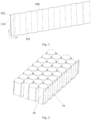
Fig. 1 is a schematic structural diagram of a liquid cooling plate according to embodiments of the present application; -
Fig. 2 is a schematic structural diagram of a liquid cooling plate cooperating with a cell according to embodiments of the present application; -
Fig. 3 is a partial schematic structural diagram of a liquid cooling plate according to embodiments of the present application; -
Fig. 4 is a schematic enlarged view of a position A of a liquid cooling plate according to the embodiment shown inFig. 3 ; -
Fig. 5 is a schematic structural diagram of a flow disturbance member of a liquid cooling cold plate according to embodiments of the present application. -
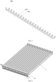
Fig. 6 is a schematic structural diagram of a liquid cooling system according to embodiments of the present application; -
Fig. 7 is a schematic structural diagram of a liquid cooling plate of a liquid cooling system according to embodiments of the present application; -
Fig. 8 is a schematic diagram of a current collecting structure of a liquid cooling system according to embodiments of the present application; -
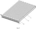
Fig. 9 is a schematic structural diagram of a battery module according to embodiments of the present application; - In the description of the present application, unless specified or limited otherwise, the terms "connected", "connected", and "fixed" should be understood broadly, for example, fixed connections, detachable connections, or integral connections; and can also be mechanical or electrical connections; can also be direct connections or indirect connections via intervening structures; can also be inner communications of two elements or interaction relationships between two elements. The specific meanings of the above terms in the present application can be understood by those skilled in the art according to specific situations.
- In the present application, unless specified or limited otherwise, a structure in which a first feature is "above" or "under" a second feature may include an embodiment in which the first feature is in direct contact with the second feature, and can also include an embodiment in which the first feature and the second feature are not in direct contact with each other, but are contacted via another feature formed therebetween. Furthermore, a first feature "on", "above" or "on top of" a second feature includes an embodiment in which the first feature is right or obliquely "on", "above" or "on top of" the second feature, and the first feature is at a height greater than that of the second feature. The first feature "below", "under", and "on the bottom of" the second feature includes the first feature "directly below" and "diagonally below" the second feature, and the first feature is horizontally less than the second feature.
- In the description of this embodiment, orientation or position relationships of terms such as 'up', 'down', 'left', 'right', 'front', and 'rear' are based on orientation or position relationships shown in the drawings, which are used for ease of description and simplifying operations, but do not indicate or imply that a device or element referred to must have a specific orientation, or be constructed and operated in a specific orientation, and therefore cannot be construed as limitations to this application. In addition, the terms "first" and "second" are used for distinguishing in terms of description, and do not have a special meaning.
- Referring to
Fig. 1 to Fig. 5 , embodiments of the present application provide aliquid cooling plate 10, where theliquid cooling plate 10 includes a liquidcooling plate body 100 and aflow disturbance member 200. The liquidcooling plate body 100 extends along a first direction, aside face 101 of the liquidcooling plate body 100 is a curved face or a flat face, and the side face of the liquidcooling plate body 100 conforms with a side wall of acell 20. A plurality offlow channels 110 extending along a first direction are provided inside the liquidcooling plate body 100, and theflow disturbance member 200 is provided in theflow channel 110. Theflow disturbance member 200 has a single helical structure and extends in the first direction. - As shown in
Fig. 1 to Fig. 2 , theliquid cooling plate 10 is a plate-shaped structure having a certain thickness and disposed between thecells 20, and contacts a side wall of thecell 20, so as to cool thecell 20. - As shown in
Fig. 1 , theliquid cooling plate 10 includes a liquidcooling plate body 100. The liquidcooling plate body 100 extends along a first direction (i.e. an X direction in the figure). The liquid cooling plate body includes twoopposite side surfaces 101, and the shape of theside surfaces 101 matches the shape of the side wall of thecell 20, so as to increase the contact area between theliquid cooling plate 10 and thecell 20, thereby increasing the heat exchange efficiency therebetween. - In a case where the
cell 20 is a cylindrical cell, theside surface 101 is a curved surface, and theliquid cooling plate 10 is a curved surface liquid cooling plate. As shown inFig. 2 , theside surface 101 of the liquidcooling plate body 100 is a wavy concave-convex curved surface extending along a first direction, the concave-convex curved surface includes a concave portion and a convex portion, and the curvature of the concave portion and the convex portion matches the diameter of thecell 20. In a case where theliquid cooling plate 10 is arranged between thecells 20, the concave portion near theside surface 101 of one side of thecell 20 is attached to the side wall of the cylindrical cell and the protruding portion is located betweenadjacent cells 20, which increase the contact area between theside surface 101 of the liquid cooling plate body and the side wall of thecell 20. The increase of the contact area facilitates heat conduction of thecell 20, so that a heat conduction rate thereof is greater and the temperature equalization performance is better, thereby improving heat exchange efficiency of theliquid cooling plate 10. - In a case where the
cell 20 is a square cell or a soft pack cell, theside surface 101 is a plane, and theliquid cooling plate 10 is a planar liquid cooling plate. In a case where theliquid cooling plate 10 is disposed between thecells 20, theplanar side surface 101 is attached to the side wall of the planar cell, so as to perform heat exchange, thereby cooling thecells 20. - As shown in
Fig. 3 , theflow channel 110 is a hollow channel arranged inside theliquid cooling plate 10, the channel extends in a first direction (i.e. an X direction in the figure). Theflow channel 110 includes a liquid inlet opening and a liquid outlet opening, the cooling liquid enters the flow channel from the liquid inlet opening, and is output from the liquid outlet opening to theliquid cooling plate 10. The cooling liquid flowing through theflow channel 110 exchanges heat with thecell 20, so as to cool thecell 20. - In some embodiments, a shape of the
flow channel 110 is consistent with a shape of a side surface of the liquidcold plate body 100. In a case where theside surface 101 of the liquidcold plate body 100 is a curved surface, theflow channel 110 is arranged in a curve shape along a first direction, and the curve-type flow channel helps enhance a flow disturbance effect of the cooling liquid in the flow channel, so as to improve liquid cooling efficiency of the liquidcold plate 10. In a case where theside surface 101 of the liquidcooling plate body 100 is a flat surface, theflow channel 110 is arranged in a straight line shape along the first direction. - As shown in
Fig. 3 to Fig. 4 , theflow disturbance member 200 has a long strip shape and a single helical structure, and the extending direction of theflow disturbance member 200 is consistent with the extending direction of theflow channel 110. Theflow disturbance member 200 is disposed between the inner wall of theflow channel 110 and the inner wall of theflow channel 110 to form a single helical channel, and the cooling liquid flows in the single helical channel. Since the cooling liquid used by the batteryliquid cooling plate 10 is generally a liquid with a low viscosity, such as water, compared with a double helical channel structure, the single helical channel used in the present application is more suitable for transporting the cooling liquid of the battery, and the single helical channel has a simple structure and a lower manufacturing cost.The cooling liquid flows in the single helical channel faster, has a higher heat exchange efficiency, and is not easily blocked. - In some embodiments, a shape of the
flow disturbance member 200 is consistent with a shape of theflow channel 110. In a case where theside surface 101 of the liquidcooling plate body 100 is a curved surface, theflow disturbance member 200 is arranged in a curved shape along the first direction, so that on one hand, the fitting degree with the shape of the flow channel is improved, and on the other hand, the flow disturbance member effect is enhanced, and the liquid cooling efficiency of theliquid cooling plate 10 is improved. In a case where theside surface 101 of the liquidcooling plate body 100 is a flat surface, theflow disturbance member 200 is arranged linearly along the first direction. - In the present application, a flow disturbance member with a single helical structure is additionally provided in the flow channel of the
liquid cooling plate 10, so as to enhance the flow disturbance effect on the cooling liquid flowing through the flow channel, increase the contact area between the cooling liquid and the flow disturbance member, and enhance the heat exchange efficiency of the cooling liquid. - In some embodiments, as shown in
Fig. 5 , theflow disturbance member 200 includes ahelical blade 210, thehelical blade 210 is provided with throughholes 220, and the throughholes 220 penetrate through thehelical blade 210 in a first direction. - As shown in
Fig. 5 , theflow disturbance member 200 is formed by helical blades, and theflow disturbance member 200 is configured as a blade-type helical structure, so that the contact area between the cooling liquid and the blade surface is increased, thereby enhancing the flow disturbance member effect and the heat exchange efficiency. - However, after the
flow disturbance member 200 is added to theflow channel 110, the flow resistance to the cooling liquid is correspondingly increased, and the pressure of the whole liquid cooling system is increased. In order to ensure that the pressure drop of the whole liquid cooling system meets the requirements, in the present application, a throughhole 220 is provided on thehelical blade 210 of theflow disturbance member 200, the throughhole 220 penetrates through thehelical blades 210, and a part of the cooling liquid flows through the throughhole 220, which can effectively reduce the flow resistance of the cooling liquid in theflow channel 110. In addition, the throughholes 220 can also enhance the effect of turbulence and improve the heat exchange efficiency. - In some embodiments, the
flow disturbance member 200 is provided with a plurality of throughholes 220, and the plurality of throughholes 220 are evenly distributed on thehelical blades 210 to ensure the uniformity of heat exchange. - In some embodiments, the cross-section of the through-
hole 220 is a regular shape such as a circle or a square, and can also be an irregular shape, which is not limited herein. - In some embodiments, intervals between adjacent
helical blades 210 of theflow disturbance member 200 can be set to be equal, so as to facilitate manufacturing of theflow disturbance member 200, simplify a manufacturing process of theflow disturbance member 200, and increase universality of theflow disturbance member 200. - After the cooling liquid flows into the
flow channel 110 from the liquid inlet opening, the cooling liquid exchanges heat with thecell 20 to increase the temperature of the cooling liquid. Therefore, in theflow channel 110, the temperature of the cooling liquid near the liquid inlet opening is higher along the flow direction of the cooling liquid, so that the heat exchange capacity of the front section (the part close to the liquid inlet opening) and the heat exchange capacity of the rear section (the part close to the liquid outlet opening) of theliquid cooling plate 10 are inconsistent. As a result, theliquid cooling plate 10 has non-uniform heat exchange. Therefore, the present application ensures uniform heat exchange through the distance between thehelical blades 210 of theflow disturbance member 200. - In some embodiments, the distances between adjacent
helical blades 210 near the liquid inlet opening is greater than the distance between adjacenthelical blades 210 near the liquid outlet opening. Specifically, by taking the center point of theflow disturbance member 200 in the first direction as a boundary, the distances between any adjacenthelical blades 210 from the end of theflow disturbance member 200 close to the liquid inlet opening to the center point are set to be equal to "a", and the distances between any adjacenthelical blades 210 from the center point to the end of theflow disturbance member 200 close to the liquid outlet opening are set to be equal to "b", where "a" is less than "b". By making the helical density of the rear half section (from the central point to the end of theflow disturbance member 200 close to the liquid inlet opening) of theflow disturbance member 200 greater than the helical density of the front half section (from the end of theflow disturbance member 200 close to the liquid inlet opening to the central point) of theflow disturbance member 200 to increase the contact area between the cooling liquid in the second half section and thehelical blades 210, the heat exchange between the cooling liquid and thehelical blades 210 is enhanced, so as to balance the heat exchange capacity of the front section and the rear section of theliquid cooling plate 10, thereby making the cooling liquid flowing through theliquid cooling plate 10 can have evenly exchange heat with thecell 20. - In some embodiments, in a direction from the liquid inlet opening to the liquid outlet opening, that is, in the direction in which the cooling liquid flows, the distances between adjacent
helical blades 210 of theflow disturbance member 200 decrease sequentially. In a case where the temperature of the cooling liquid flowing through theflow channel 110 gradually increases along with the heat exchange with thecell 20, by means of arranging the distances between adjacenthelical blades 210 of theflow disturbance member 200 to be successively reduced, the heat exchange capacity of theliquid cooling plate 10 is effectively balanced, and the uniformity of heat exchange is ensured. - In some embodiments, as shown in
Fig. 4 , a side surface of theflow channel 110 facing theflow disturbance member 200 is provided with aconvex structure 111. - Specifically, the protruding
structure 111 is a semicircular protrusion structure or a rectangular protrusion structure, which is not limited herein. A plurality of protrudingstructures 111 are distributed at intervals and evenly on an inner wall of theflow channel 110. By providing the protrudingstructures 111 in theflow channel 110, a turbulent effect of cooling liquid flowing through theflow channel 110 is promoted, thereby improving heat exchange efficiency of theliquid cooling plate 10. - In some embodiments, as shown in
Fig. 3 to Fig. 4 , the cross section of theflow channel 110 is circular. Theinner flow channel 110 of theliquid cooling plate 10 is formed by a plurality of circular channels. On one hand, the circular channels can enhance the overall structural strength of theliquid cooling plate 10, and can ensure the uniform heat exchange of thecell 20. On the other hand, the circular channel can better match theflow disturbance member 200 with a helical structure, and the edge of thehelical blade 210 of theflow disturbance member 200 is more easily attached to the inner wall of the circular channel, so that a helical channel is formed in theflow channel 110, which helps improve the heat exchange efficiency of theliquid cooling plate 10. - In some embodiments, as shown in
Fig. 1 , a plurality offlow channels 110 penetrate the liquidcooling plate body 100, and the plurality offlow channels 110 are arranged in parallel in a second direction perpendicular to the first direction. - Specifically, the plurality of
flow channels 110 all extend in the first direction, the plurality offlow channels 110 all penetrate the liquidcooling plate body 100 in the first direction, and the plurality offlow channels 110 are arranged in parallel at intervals in the second direction (i.e. a Y direction in the figure), so as to form a parallel arrangement. In a first direction, theliquid cooling plate 10 includes afirst end surface 102 and asecond end surface 102 opposite to each other, as shown inFig. 3 . A plurality of liquid inlet openings are arranged along a second direction (i.e. a Y direction in the figure), and the plurality of liquid inlet openings are respectively in communication withcorresponding flow channels 110. On the second end surface of theliquid cooling plate 10, a plurality of liquid outlet openings are arranged along a second direction (i.e. a direction Y in the figure), the liquid outlet openings communicate with the correspondingchannels 110. In the process of cooling thecell 20 by theliquid cooling plate 10, the cooling liquid is distributed to the plurality of liquid inlet openings by the liquid inlet collector and is delivered to thecorresponding flow channel 110. The cooling liquid flows in theflow channel 110 and forms convection heat exchange with thecell 20, and finally flows out of the liquid outlet openings and is converged into the liquid outlet collector. In the present application, the plurality offlow channels 110 are arranged in parallel to cool acell 20, so that the cooling effect is more uniform and the heat exchange efficiency is higher. - It should be noted that the
flow channels 110 in theliquid cooling plate 10 can also be arranged in series, or arranged in combination of series connection and parallel connection, which is not limited herein. - The present application provides a liquid cooling plate. A flow disturbance member is disposed in a flow channel of the liquid cooling plate. The flow disturbance member is of a single helical structure, and a helical extension direction of the single helical structure is the same as an extension direction of the flow channel. After entering the flow channel, a cooling liquid forms a strong flow disturbance due to the single helical structure, thereby increasing the heat exchange efficiency of a liquid cooling pipe.
- As shown in
Fig. 6 to Fig. 8 , which are schematic structural diagrams of a liquid cooling system provided in the present application. The liquid cooling system includes aliquid cooling plate 10 and acollector 2001. - A flow channel is provided inside the
liquid cooling plate 10, and the flow channel includes a liquid inlet end and a liquid outlet end. - The
collector 2001 includes aliquid inlet collector 2101 and aliquid outlet collector 2201, in which theliquid inlet collector 2101 is in communication with a liquid inlet end, and theliquid outlet collector 2201 is in communication with a liquid outlet end; - The
liquid cooling plate 10 extends in a first direction, theliquid cooling plate 10 includes two opposite ends in the first direction, and a liquid inlet end, a liquid outlet end, aliquid inlet collector 2101 and aliquid outlet collector 2201 are located at the same end of theliquid cooling plate 10. - Specifically, the
liquid cooling plate 10 is a plate-shaped structure having a certain thickness, and a channel, i.e. a flow channel, through which a cooling liquid circulates is provided inside theliquid cooling plate 10. Theliquid cooling plate 10 is arranged on at least one side of the cell, and a side face of theliquid cooling plate 10 is in contact with a side wall of the cell. The cooling liquid flowing in the flow channel exchanges heat with the cell, so as to cool and cool the cell, thereby improving the service life of the cell. - The
collector 2001 is used to provide cooling liquid for theliquid cooling plate 10. Theliquid inlet collector 2101 is in communication with the liquid inlet end of the flow channel and is used to input the cooling liquid to the flow channel. The cooling liquid flows through the flow channel and exchanges heat with the cell, the temperature of the cooling liquid after heat exchange rises, and then is output through the liquid outlet end of the flow channel and collected in theliquid outlet collector 2201, so as to complete the cooling of the cell. - In some embodiments, as shown in
Fig. 7 , along a first direction (i.e. an X direction), theliquid cooling plate 10 includes afirst end 101 and asecond end 102 opposite to each other. Both a liquid inlet end and a liquid outlet end of the flow channel are located at thefirst end 101, theliquid inlet collector 2101 is located on a side close to thefirst end 101 and is in communication with the liquid inlet end, and theliquid outlet collector 2201 is located on a side close to thefirst end 101 and is in communication with the liquid outlet end. - In the present application, the liquid inlet end, the liquid outlet end, the
liquid inlet collector 2101 and theliquid outlet collector 2201 of theliquid cooling plate 10 are arranged at the same end of theliquid cooling plate 10, so that on one hand, the liquid inlet end is integrated with theliquid inlet collector 2101, the liquid outlet end is integrated with theliquid outlet collector 2201 to facilitate quick connection, and on the other hand, thecollector 2001 and the connecting pipeline are arranged at the same side of theliquid cooling plate 10, so that the space occupied by the liquid cooling system in the battery module is saved. - In some embodiments, as shown in
Fig. 6 to Fig. 8 , in order to facilitate the connection between the liquid inlet end and theliquid inlet collector 2101 and the connection between the liquid outlet end and theliquid outlet collector 2201, a liquid inlet opening 110 is provided at a liquid inlet end, aliquid outlet opening 120 is provided at a liquid outlet end, aliquid inlet connector 230 is provided on aliquid inlet collector 2101, and a liquid outlet connector 240 is provided on theliquid outflow collector 2201. The liquid inlet opening 110 is connected to theliquid inlet connector 230, and theliquid outlet opening 120 is connected to the liquid outlet connector 240 Thus, the liquid inlet end is communicated with theliquid inlet collector 2101, and the liquid outlet end is communicated with theliquid outlet collector 2201. - In some embodiments, the liquid inlet opening 110 is connected to the
liquid inlet connector 230 in a plugged manner, and theliquid outlet opening 120 is connected to the liquid outlet connector 240 in a plugged manner, so as to facilitate quick connection between thecollector 2001 and theliquid cooling plate 10. - For example, as shown in
Fig. 7 , theliquid inlet opening 110 and the liquid outlet opening 120 of theliquid cooling plate 10 are sockets, the sockets include a insertinghole 1111, and an outer periphery of the socket is provided with aconvex lug 112. As shown inFig. 3 , theliquid inlet connector 230 and the liquid outlet connector 240 of thecollector 2001 is a quick connector, and an outer diameter of the quick connector matches an inner diameter of the insertinghole 1111, so that in a case where the quick connector is inserted into the insertinghole 1111. The outer periphery of the quick plug connector is provided with aconvex portion 241, and an inner wall of the insertinghole 1111 is provided with a concave portion matching the convex portion, so that during plugging, the socket is connected and fixed to the quick plug connector; The quick plug connector is further provided with abuckle 250. A side of thebuckle 250 facing the quick plug connector is provided with a groove 251 matching theconvex lug 112, so that during plugging, theconvex lug 112 is embedded in the groove 251. The socket and the quick plug are locked, falling-off is avoided, and the reliability of the connection between theliquid cooling plate 10 and thecollector 2001 is improved. - It should be noted that, connection structures of the
liquid inlet opening 110 and theliquid inlet connector 230, and connection structures of theliquid outlet opening 120 and the liquid outlet connector 240 are not limited to the specific structures in the foregoing embodiments, and other forms of plug-in connection structures are also acceptable. The connection manner between theliquid inlet opening 110 and theliquid inlet connector 230, and the connection manner between theliquid outlet opening 120 and the liquid outlet connector 240 are not limited to the foregoing plug-in connection manners, and can also be other connection manners, which are not specifically limited herein. - In some embodiments, as shown in
Fig. 6 , theliquid inlet opening 110, theliquid outlet opening 120, theliquid inlet connector 230, and the liquid outlet connector 240 all extend along a second direction perpendicular to the first direction, the liquid inlet opening 110 is connected to theliquid inlet connector 230 along the second direction, and theliquid outlet opening 120 is connected to the liquid outlet connector 240 along the second direction, so as to facilitate quick connection between theliquid cooling plate 10 and thecollector 2001, thereby effectively improving the assembling efficiency. - As shown in
Fig. 6 , the insertingholes 1111 of theliquid inlet opening 110 and the liquid outlet opening 120 have the same opening direction and face towards the second direction (i.e. Z direction). Thecollector 2001 extends along a third direction (i.e. a Y direction) perpendicular to both the first direction and the second direction, theliquid inlet connector 230 and the liquid outlet connector 240 are connected to thecollector 2001 via a short pipe, and the short pipe is perpendicular to the collector 2001 (i.e. extending along the Z direction). In a case where thecollector 2001 is connected to theliquid cooling plate 10, theliquid inlet connector 230 is inserted into the insertinghole 1111 of the liquid inlet opening 110 in the Z direction, and the liquid outlet connector 240 is inserted into the insertinghole 1111 of the liquid outlet opening 120 in the Z direction, so that theliquid inlet collector 2101 is communicated with theliquid inlet opening 110, and theliquid outlet collector 2201 is communicated with theliquid outlet opening 120, which can effectively improve the connection efficiency. - In some embodiments, as shown in
Fig. 7 , theliquid cooling plate 10 further includes a connecting member 130, the connecting member 130 is connected to one end of theliquid cooling plate 10, and theliquid inlet opening 110 and the liquid outlet opening 120 are disposed on two opposite sides of the connecting member 130. A plurality of channels are provided in the connection member 130, and the plurality of channels are configured to communicate theliquid inlet opening 110 and the flow channel, and communicate theliquid outlet opening 120 and the flow channel. - As shown in
Fig. 7 , the connecting member 130 extends along the first direction, and in the third direction, the connecting member 130 includes two opposite sides, the two sides of the connecting member 130 are respectively provided with afirst extension portion 131 and asecond extension portion 132 which are perpendicular to the connecting member 130, the liquid inlet opening 110 is provided on thefirst extension portion 131, and theliquid outlet opening 120 is provided on thesecond extension portion 132, so that the opening direction of the insertingholes 1111 of theliquid inlet opening 110 and the liquid outlet opening 120 faces towards the second direction, it is convenient for theliquid inlet opening 110 and the liquid outlet opening 120 to dock with thecollector 2001 in the second direction. A channel is provided inside the connection member 130, the liquid inlet opening 110 is in communication with thefirst extension portion 131, and thefirst extension portion 131 is in communication with the liquid inlet end of the flow channel via the channel. Theliquid outlet opening 120 is in communication with thesecond extension portion 132, and thesecond extension portion 132 is in communication with the liquid outlet end of the flow channel via the channel. - An opening direction of the inserting
holes 1111 of theliquid inlet opening 110 and theliquid outlet opening 120 is adjusted by means of the connecting member 130, so that the opening directions of the insertingholes 1111 all face towards a second direction, so that theliquid inlet opening 110 and the liquid outlet opening 120 are connected in the second direction. Meanwhile, theliquid inlet opening 110 and the liquid outlet opening 120 are arranged at two opposite sides of the connecting member 130, thereby avoiding interference between theliquid inlet connector 230 and a connecting pipeline thereof, and the liquid outlet connector 240 and the connecting pipeline thereof during connection, and affecting the connection reliability. - In some embodiments, the
liquid inlet collector 2101 and theliquid outlet collector 2201 are integrally formed, so as to improve the integration of thecollector 2001, simplify the process, and save the space occupied by thecollector 2001. - As shown in
Fig. 8 , thecollector 2001 includes acollector body 201, thecollector body 201 extends in a third direction, a liquid inlet collector channel and a liquid outlet collector channel extending in the third direction are disposed inside thecollector body 201, a coolingliquid inlet 211 is disposed at one end of the liquid inlet collector channel, and a coolingliquid outlet 221 is disposed at one end of the liquid outlet collector channel. In the second direction, thecollector body 201 includes two opposite sides, and one side of thecollector body 201 is connected to theliquid inlet connector 230 and the liquid outlet connector 240, theliquid inlet connector 230 is in communication with the liquid inlet collector channel, and the liquid outlet connector 240 is in communication with the liquid outlet collector channel. Theliquid inlet connector 230 is connected to thecollector body 201 by means of a firstshort pipe 260, the liquid outlet connector 240 is connected to thecollector body 201 by means of a secondshort pipe 270, and the lengths of the firstshort pipe 260 and the secondshort pipe 270 are different, so as to avoid interference between theliquid inlet connector 230 and the liquid outlet connector 240 during installation, which affect the reliability of the connection between themain collecting body 2001 and theliquid cooling plate 10. Thecollector body 201, the firstshort pipe 260 and the secondshort pipe 270 can also be integrally formed. - In some embodiments, as shown in
Fig. 6 , the liquid cooling system includes a plurality ofliquid cooling plates 10. The plurality ofliquid cooling plates 10 are arranged in parallel, and communicate with onecollector 2001 to form a parallel structure. - As shown in
Fig. 5 , the liquid cooling system includes a plurality ofliquid cooling plates 10. The plurality ofliquid cooling plates 10 are arranged in parallel in a third direction, and the plurality ofliquid cooling plates 10 are arranged in parallel. Aliquid inlet opening 110 and a liquid outlet opening 120 of theliquid cooling plate 10 are both located at afirst end 101 of theliquid cooling plate 10. Thecollector 2001 is disposed close to thefirst end 101 of theliquid cooling plate 10, multiple combinations ofliquid inlet connectors 230 and liquid outlet connectors 240 are arranged side by side on thecollector body 201 along a third direction, and oneliquid inlet connector 230 and one liquid outlet connector 240 are correspondingly connected to oneliquid cooling plate 10. In the present application, a liquid-cooling system is connected in parallel using a plurality of liquid cooling plates, which can effectively reduce the flow resistance of the entire liquid-cooling system and improve the flow uniformity of the liquid-cooling system. - In some embodiments, as shown in
Fig. 6 to Fig. 7 , in the second direction, theliquid cooling plate 10 includes atop end 103 and abottom end 104 opposite to each other, and thecollector 2001 overlaps thetop end 103 or thebottom end 104. As shown inFig. 6 , a part of thecollector body 201 can be overlapped at the edge of thetop end 103 of theliquid cooling plate 10 located at thefirst end 101, so that installation space in the second direction is reasonably utilized, thereby reducing space occupied by the liquid cooling system in the first direction, reducing space occupation ratio of the liquid cooling system in the battery module or the battery pack, and reducing costs of the liquid cooling system at the same time. - In some embodiments, the flow channel is U-shaped, one end of the U-shaped flow channel is a liquid inlet end, and the other end of the U-shaped flow channel is a liquid outlet end.
- Specifically, in the
liquid cooling plate 10, a plurality of parallel flow channels are included along a first direction, and the flow channel include a liquid inlet channel and a liquid outlet channel, the liquid inlet end of the liquid inlet channel and the liquid outlet end of the liquid outlet channel are both located at thefirst end 101 of theliquid cooling plate 10, and are located at thesecond end 102 of theliquid cooling plate 10, the liquid inlet channel is in communication with the liquid outlet channel to form a U-shaped flow channel, and the cooling liquid enters the U-shaped flow channel from the liquid inlet end of thefirst end 101 of theliquid cooling plate 10, theliquid crystal panel 10 is output from the liquid outlet end of thefirst end 101 after heat exchange with the cells. The flow channels in theliquid cooling plate 10 are configured to be U-shaped flow channels, so that theliquid cooling plate 10 has better temperature uniformity and a better liquid cooling effect. - In some embodiments, the
liquid cooling plate 10 is contoured in a wavy shape in a first direction. - As shown in
Fig. 5 , along the third direction, theliquid cooling plate 10 includes two opposite side faces, and the two side faces of theliquid cooling plate 10 are configured as wavy concave-convex curved surfaces, By arranging the side surface of theliquid cooling plate 10 to be a wavy concave-convex curved surface, the concave portion of theliquid cooling plate 10 conforms the side wall of the cell of the cylindrical battery module, a convex portion of theliquid cooling plate 10 is located between adjacent cells, which can increase the contact area between the side surface of theliquid cooling plate 10 and the side wall of the cell, the increase of the contact area facilitates heat conduction of the cell, has a fast heat conduction rate and good temperature equalization performance, and facilitates improvement of heat exchange efficiency of theliquid cooling plate 10. - The present application further provides a battery module, including the liquid cooling system above.
- As shown in
Fig. 9 , the battery module includes a cell group and a liquid cooling system. - The cell group includes a plurality of
cells 300, and the plurality ofcells 300 are arranged in an array, wherein thecells 300 arecylindrical cells 300 orsquare cells 300, but are not limited thereto. - The liquid cooling system includes a
liquid cooling plate 10 and acollector 2001, a flow channel is provided inside theliquid cooling plate 10, and the flow channel includes a liquid inlet end and a liquid outlet end. Thecollector 2001 includes aliquid inlet collector 2101 and aliquid outlet collector 2201, theliquid inlet collector 2101 is in communication with a liquid inlet end, and theliquid outlet collector 2201 is in communication with a liquid outlet end. Theliquid cooling plate 10 extends in a first direction, theliquid cooling plate 10 includes two opposite ends in the first direction, and a liquid inlet end, a liquid outlet end, aliquid inlet collector 2101 and aliquid outlet collector 2201 are located at the same end of theliquid cooling plate 10. - The
liquid cooling plate 10 is located between two adjacent rows or two adjacent columns ofcells 300, and a side surface of theliquid cooling plate 10 is in contact with a side wall of thecell 300, the cooling liquid is distributed by aliquid inlet collector 2101 and is delivered into a plurality of flow channels from a liquid inlet end, and the cooling liquid flows in the flow channels and forms convection heat exchange with thecell 300, then, theliquid cooling plate 10 is output from the liquid outlet end, and finally collected in theliquid outlet collector 2201, so that the liquid cooling system cools thecells 300. - In some embodiments, the battery module further includes a housing. The housing has an accommodating cavity. The cell group, the liquid cooling system, the liquid inlet collector and the liquid outlet collector are all accommodated in the accommodating cavity.
- The present application provides a liquid cooling system and a battery module. A liquid inlet end, a liquid outlet end, a liquid inlet collector, and a liquid outlet collector of a liquid cooling plate are disposed at the same end of the liquid cooling plate, on the one hand, the liquid inlet end is convenient to be connected to the liquid inlet collector, and the liquid outlet end is convenient to be connected to the liquid outlet collector in a concentrated and rapid manner, on the other hand, the collector and the connection pipeline are disposed on the same side of the liquid cooling plate, so that space occupied by the liquid-cooling system in the battery module is saved.
Claims (19)
- A liquid cooling plate, comprising a liquid cooling plate body and a flow disturbance member;the liquid cooling plate body extends along a first direction, and a side surface of the liquid cooling plate body is a curved surface or a flat surface, wherein the side surface of the liquid cooling plate body conforms with a side wall of a cell;a plurality of flow channels extending along the first direction are provided inside the liquid cooling plate body, and the flow disturbance member is provided in each of the plurality of flow channels;wherein the flow disturbance member has a single helical structure and extends along the first direction.
- Liquid cooling plate of claim 1, wherein the flow disturbance member comprises a plurality of helical blades, the plurality of helical blades are provided with a plurality of through holes, and the plurality of through holes penetrate the plurality of helical blades in the first direction.
- Liquid cooling plate of claim 2, wherein the flow disturbance member is provided with the plurality of through holes, and the plurality of through holes are evenly distributed on the helical blades.
- Liquid cooling plate of claim 2, wherein intervals between adjacent helical blades of the flow disturbance member are equal.
- Liquid cooling plate of claim 2, wherein the flow channel comprises a liquid inlet opening and a liquid outlet opening, and a distance between adjacent helical blades near the liquid inlet opening is greater than a distance between adjacent helical blades near the liquid outlet opening.
- Liquid cooling plate of claim 2, wherein the flow channel comprises a liquid inlet opening and a liquid outlet opening, and in a direction from the liquid inlet opening to the liquid outlet opening, intervals between adjacent helical blades of the flow disturbance member sequentially decrease.
- Liquid cooling plate of any one of claims 1 to 6, wherein a side surface of the flow channel facing the flow disturbance member is provided with a convex structure.
- Liquid cooling plate of any one of claims 1 to 6, wherein a cross section of the flow channel is circular.
- Liquid cooling plate of any one of claims 1 to 6, wherein the flow channel penetrates through the liquid cooling plate body, and the plurality of flow channels are arranged in parallel to each other in a second direction perpendicular to the first direction.
- A liquid cooling system, comprising:the liquid cooling plate of any one of claims 1-9;a collector;a flow channel comprising a liquid inlet end and a liquid outlet end;the collector comprises a liquid inlet collector and a liquid outlet collector, the liquid inlet collector is communicated with the liquid inlet end, and the liquid outlet collector is communicated with the liquid outlet end;the liquid cooling plate extends in a first direction, the liquid cooling plate comprises two opposite ends in the first direction, and the liquid inlet end, the liquid outlet end, the liquid inlet collector, and the liquid outlet collector are located at a same end of the liquid cooling plate.
- Liquid cooling system of claim 10, wherein the liquid inlet end is provided with a liquid inlet opening, and the liquid outlet end is provided with a liquid outlet opening;the liquid inlet collector comprises a liquid inlet connector, and the liquid outlet collector comprises a liquid outlet connector;the liquid inlet opening is connected to the liquid inlet connector in a pluggable manner, and the liquid outlet opening is connected to the liquid outlet connector in a pluggable manner.
- Liquid cooling system of claim 11, wherein the liquid inlet opening, the liquid outlet opening, the liquid inlet connector, and the liquid outlet connector all extend along a second direction perpendicular to the first direction, the liquid inlet opening is butt-jointed to the liquid inlet connector along the second direction, and the liquid outlet opening is butt-jointed to the liquid outlet connector along the second direction.
- Liquid cooling system of claim 12, wherein the liquid cooling plate further comprises a connecting member, the connecting member is connected to one end of the liquid cooling plate, and the liquid inlet opening and the liquid outlet opening are disposed on two opposite sides of the connecting member; a plurality of channels are provided in the connecting member, and each of the plurality of channels is configured to communicate the liquid inlet opening with the flow channel, and to communicate the liquid outlet opening with the flow channel.
- Liquid cooling system of any one of claims 10-13, wherein the liquid inlet collector and the liquid outlet collector are integrally formed.
- Liquid cooling system of claim 14, wherein the liquid cooling system comprises a plurality of liquid cooling plates, the plurality of liquid cooling plates are arranged in parallel, and the plurality of liquid cooling plates are in communication with one collector to form a parallel structure.
- Liquid cooling system of claim 12, wherein along the second direction, the liquid cooling plate comprises a top end and a bottom end that are opposite to each other, and the collector overlaps the top end or the bottom end.
- Liquid cooling system of any one of claims 10 to 13, wherein the flow channel is U-shaped, one end of a U-shaped flow channel is the liquid inlet end, and the other end of the U-shaped flow channel is the liquid outlet end.
- Liquid cooling system of any one of claims 10 to 13, wherein the liquid cooling plate is in a wave shape along the first direction.
- A battery module, comprising the liquid cooling system of any one of claims 10 to 18.
Applications Claiming Priority (4)
| Application Number | Priority Date | Filing Date | Title |
|---|---|---|---|
| CN202321712225.0U CN220021295U (en) | 2023-06-30 | 2023-06-30 | Liquid cooling plate and battery module |
| CN202310800797.2A CN116722259A (en) | 2023-06-30 | 2023-06-30 | Liquid cooling plate and battery module |
| CN202321712215.7U CN220341321U (en) | 2023-06-30 | 2023-06-30 | Liquid cooling system and battery module |
| PCT/CN2024/101463 WO2025002141A1 (en) | 2023-06-30 | 2024-06-25 | Liquid cooling plate, liquid cooling system and battery module |
Publications (2)
| Publication Number | Publication Date |
|---|---|
| EP4535511A1 true EP4535511A1 (en) | 2025-04-09 |
| EP4535511A4 EP4535511A4 (en) | 2025-12-10 |
Family
ID=93937661
Family Applications (1)
| Application Number | Title | Priority Date | Filing Date |
|---|---|---|---|
| EP24827785.7A Pending EP4535511A4 (en) | 2023-06-30 | 2024-06-25 | LIQUID COOLING PLATE, LIQUID COOLING SYSTEM AND BATTERY MODULE |
Country Status (6)
| Country | Link |
|---|---|
| US (1) | US20250158165A1 (en) |
| EP (1) | EP4535511A4 (en) |
| JP (1) | JP2025528590A (en) |
| KR (1) | KR20250004696A (en) |
| DE (1) | DE212024000056U1 (en) |
| WO (1) | WO2025002141A1 (en) |
Family Cites Families (11)
| Publication number | Priority date | Publication date | Assignee | Title |
|---|---|---|---|---|
| JP2010276319A (en) * | 2009-06-01 | 2010-12-09 | Sumitomo Light Metal Ind Ltd | Heat exchanger |
| JP2014186944A (en) * | 2013-03-25 | 2014-10-02 | Toyoda Gosei Co Ltd | Battery device |
| KR101995576B1 (en) * | 2018-12-31 | 2019-07-03 | 대림로얄이앤피(주) | Tube structure for improving thermal efficiency |
| CN218975566U (en) * | 2022-12-01 | 2023-05-05 | 湖北亿纬动力有限公司 | Cooling plate and battery pack |
| CN115764070A (en) * | 2022-12-01 | 2023-03-07 | 湖北亿纬动力有限公司 | Cooling plate and battery pack |
| CN219106295U (en) * | 2022-12-30 | 2023-05-30 | 湖北亿纬动力有限公司 | Liquid cooling system and battery module |
| CN116111228A (en) * | 2022-12-30 | 2023-05-12 | 湖北亿纬动力有限公司 | A battery module and a battery pack with the battery module |
| CN116231148B (en) * | 2023-01-06 | 2024-05-28 | 小米汽车科技有限公司 | Liquid cooling plate assembly, cooling system, battery pack and vehicle |
| CN116722259A (en) * | 2023-06-30 | 2023-09-08 | 惠州亿纬锂能股份有限公司 | Liquid cooling plate and battery module |
| CN220341321U (en) * | 2023-06-30 | 2024-01-12 | 惠州亿纬锂能股份有限公司 | Liquid cooling system and battery module |
| CN220021295U (en) * | 2023-06-30 | 2023-11-14 | 惠州亿纬锂能股份有限公司 | Liquid cooling plate and battery module |
-
2024
- 2024-06-25 KR KR1020247035774A patent/KR20250004696A/en active Pending
- 2024-06-25 WO PCT/CN2024/101463 patent/WO2025002141A1/en not_active Ceased
- 2024-06-25 JP JP2025514822A patent/JP2025528590A/en active Pending
- 2024-06-25 DE DE212024000056.6U patent/DE212024000056U1/en active Active
- 2024-06-25 EP EP24827785.7A patent/EP4535511A4/en active Pending
-
2025
- 2025-01-13 US US19/019,454 patent/US20250158165A1/en active Pending
Also Published As
| Publication number | Publication date |
|---|---|
| EP4535511A4 (en) | 2025-12-10 |
| US20250158165A1 (en) | 2025-05-15 |
| WO2025002141A1 (en) | 2025-01-02 |
| DE212024000056U1 (en) | 2025-01-28 |
| JP2025528590A (en) | 2025-08-28 |
| KR20250004696A (en) | 2025-01-08 |
Similar Documents
| Publication | Publication Date | Title |
|---|---|---|
| CN219106281U (en) | A liquid cooling system and battery module | |
| CN217426893U (en) | Cooling structure and battery pack | |
| CN118198623A (en) | Batteries and electrical devices | |
| CN113314726B (en) | Arrow-feather-shaped bipolar plate of proton exchange membrane fuel cell | |
| CN116722259A (en) | Liquid cooling plate and battery module | |
| CN116487772A (en) | Liquid cooling plate and battery module | |
| CN220341321U (en) | Liquid cooling system and battery module | |
| CN220021295U (en) | Liquid cooling plate and battery module | |
| CN213989035U (en) | A new type of module frame and cell module | |
| CN219917296U (en) | Liquid cooling system and battery pack | |
| EP4535511A1 (en) | Liquid cooling plate, liquid cooling system and battery module | |
| CN219066953U (en) | Heat exchange assembly, battery module and battery pack for battery | |
| CN117154281A (en) | Battery liquid cooling system, battery core module and battery pack | |
| CN212874592U (en) | Heat exchange assembly and heat exchange device | |
| CN219917291U (en) | Battery pack | |
| CN218731384U (en) | Monomer electric core and battery module of integrated thermal management structure | |
| CN217485574U (en) | A battery device and electric vehicle | |
| CN216648428U (en) | Battery heat exchange plate and battery pack | |
| CN216597749U (en) | Power battery thermal management system | |
| CN216311896U (en) | Battery module structure | |
| CN213340500U (en) | Square battery module | |
| CN224138187U (en) | Thermal management components, battery packs and battery stacks | |
| CN222422069U (en) | Liquid cooling battery module | |
| CN219203379U (en) | Side panel structure and battery module | |
| CN222654063U (en) | Battery pack and power-using device |
Legal Events
| Date | Code | Title | Description |
|---|---|---|---|
| STAA | Information on the status of an ep patent application or granted ep patent |
Free format text: STATUS: UNKNOWN |
|
| STAA | Information on the status of an ep patent application or granted ep patent |
Free format text: STATUS: THE INTERNATIONAL PUBLICATION HAS BEEN MADE |
|
| PUAI | Public reference made under article 153(3) epc to a published international application that has entered the european phase |
Free format text: ORIGINAL CODE: 0009012 |
|
| STAA | Information on the status of an ep patent application or granted ep patent |
Free format text: STATUS: REQUEST FOR EXAMINATION WAS MADE |
|
| 17P | Request for examination filed |
Effective date: 20250103 |
|
| AK | Designated contracting states |
Kind code of ref document: A1 Designated state(s): AL AT BE BG CH CY CZ DE DK EE ES FI FR GB GR HR HU IE IS IT LI LT LU LV MC ME MK MT NL NO PL PT RO RS SE SI SK SM TR |
|
| A4 | Supplementary search report drawn up and despatched |
Effective date: 20251107 |
|
| RIC1 | Information provided on ipc code assigned before grant |
Ipc: H01M 10/613 20140101AFI20251103BHEP Ipc: H01M 10/643 20140101ALI20251103BHEP Ipc: H01M 10/6555 20140101ALI20251103BHEP Ipc: H01M 10/6557 20140101ALI20251103BHEP Ipc: H01M 10/6568 20140101ALI20251103BHEP Ipc: F28F 1/02 20060101ALI20251103BHEP Ipc: F28F 1/40 20060101ALI20251103BHEP |