EP4535469A1 - Fuel cell system - Google Patents
Fuel cell system Download PDFInfo
- Publication number
- EP4535469A1 EP4535469A1 EP23835108.4A EP23835108A EP4535469A1 EP 4535469 A1 EP4535469 A1 EP 4535469A1 EP 23835108 A EP23835108 A EP 23835108A EP 4535469 A1 EP4535469 A1 EP 4535469A1
- Authority
- EP
- European Patent Office
- Prior art keywords
- supply
- amount
- air
- fuel cell
- cell system
- Prior art date
- Legal status (The legal status is an assumption and is not a legal conclusion. Google has not performed a legal analysis and makes no representation as to the accuracy of the status listed.)
- Pending
Links
Images





Classifications
-
- H—ELECTRICITY
- H01—ELECTRIC ELEMENTS
- H01M—PROCESSES OR MEANS, e.g. BATTERIES, FOR THE DIRECT CONVERSION OF CHEMICAL ENERGY INTO ELECTRICAL ENERGY
- H01M8/00—Fuel cells; Manufacture thereof
- H01M8/04—Auxiliary arrangements, e.g. for control of pressure or for circulation of fluids
- H01M8/04223—Auxiliary arrangements, e.g. for control of pressure or for circulation of fluids during start-up or shut-down; Depolarisation or activation, e.g. purging; Means for short-circuiting defective fuel cells
- H01M8/04225—Auxiliary arrangements, e.g. for control of pressure or for circulation of fluids during start-up or shut-down; Depolarisation or activation, e.g. purging; Means for short-circuiting defective fuel cells during start-up
-
- H—ELECTRICITY
- H01—ELECTRIC ELEMENTS
- H01M—PROCESSES OR MEANS, e.g. BATTERIES, FOR THE DIRECT CONVERSION OF CHEMICAL ENERGY INTO ELECTRICAL ENERGY
- H01M8/00—Fuel cells; Manufacture thereof
- H01M8/04—Auxiliary arrangements, e.g. for control of pressure or for circulation of fluids
- H01M8/04223—Auxiliary arrangements, e.g. for control of pressure or for circulation of fluids during start-up or shut-down; Depolarisation or activation, e.g. purging; Means for short-circuiting defective fuel cells
- H01M8/04268—Heating of fuel cells during the start-up of the fuel cells
-
- H—ELECTRICITY
- H01—ELECTRIC ELEMENTS
- H01M—PROCESSES OR MEANS, e.g. BATTERIES, FOR THE DIRECT CONVERSION OF CHEMICAL ENERGY INTO ELECTRICAL ENERGY
- H01M8/00—Fuel cells; Manufacture thereof
- H01M8/04—Auxiliary arrangements, e.g. for control of pressure or for circulation of fluids
- H01M8/04298—Processes for controlling fuel cells or fuel cell systems
- H01M8/043—Processes for controlling fuel cells or fuel cell systems applied during specific periods
- H01M8/04302—Processes for controlling fuel cells or fuel cell systems applied during specific periods applied during start-up
-
- H—ELECTRICITY
- H01—ELECTRIC ELEMENTS
- H01M—PROCESSES OR MEANS, e.g. BATTERIES, FOR THE DIRECT CONVERSION OF CHEMICAL ENERGY INTO ELECTRICAL ENERGY
- H01M8/00—Fuel cells; Manufacture thereof
- H01M8/04—Auxiliary arrangements, e.g. for control of pressure or for circulation of fluids
- H01M8/04298—Processes for controlling fuel cells or fuel cell systems
- H01M8/04313—Processes for controlling fuel cells or fuel cell systems characterised by the detection or assessment of variables; characterised by the detection or assessment of failure or abnormal function
- H01M8/0432—Temperature; Ambient temperature
-
- H—ELECTRICITY
- H01—ELECTRIC ELEMENTS
- H01M—PROCESSES OR MEANS, e.g. BATTERIES, FOR THE DIRECT CONVERSION OF CHEMICAL ENERGY INTO ELECTRICAL ENERGY
- H01M8/00—Fuel cells; Manufacture thereof
- H01M8/04—Auxiliary arrangements, e.g. for control of pressure or for circulation of fluids
- H01M8/04298—Processes for controlling fuel cells or fuel cell systems
- H01M8/04313—Processes for controlling fuel cells or fuel cell systems characterised by the detection or assessment of variables; characterised by the detection or assessment of failure or abnormal function
- H01M8/0432—Temperature; Ambient temperature
- H01M8/04358—Temperature; Ambient temperature of the coolant
-
- H—ELECTRICITY
- H01—ELECTRIC ELEMENTS
- H01M—PROCESSES OR MEANS, e.g. BATTERIES, FOR THE DIRECT CONVERSION OF CHEMICAL ENERGY INTO ELECTRICAL ENERGY
- H01M8/00—Fuel cells; Manufacture thereof
- H01M8/04—Auxiliary arrangements, e.g. for control of pressure or for circulation of fluids
- H01M8/04298—Processes for controlling fuel cells or fuel cell systems
- H01M8/04313—Processes for controlling fuel cells or fuel cell systems characterised by the detection or assessment of variables; characterised by the detection or assessment of failure or abnormal function
- H01M8/04492—Humidity; Ambient humidity; Water content
- H01M8/04507—Humidity; Ambient humidity; Water content of cathode reactants at the inlet or inside the fuel cell
-
- H—ELECTRICITY
- H01—ELECTRIC ELEMENTS
- H01M—PROCESSES OR MEANS, e.g. BATTERIES, FOR THE DIRECT CONVERSION OF CHEMICAL ENERGY INTO ELECTRICAL ENERGY
- H01M8/00—Fuel cells; Manufacture thereof
- H01M8/04—Auxiliary arrangements, e.g. for control of pressure or for circulation of fluids
- H01M8/04298—Processes for controlling fuel cells or fuel cell systems
- H01M8/04313—Processes for controlling fuel cells or fuel cell systems characterised by the detection or assessment of variables; characterised by the detection or assessment of failure or abnormal function
- H01M8/04537—Electric variables
- H01M8/04544—Voltage
- H01M8/04559—Voltage of fuel cell stacks
-
- H—ELECTRICITY
- H01—ELECTRIC ELEMENTS
- H01M—PROCESSES OR MEANS, e.g. BATTERIES, FOR THE DIRECT CONVERSION OF CHEMICAL ENERGY INTO ELECTRICAL ENERGY
- H01M8/00—Fuel cells; Manufacture thereof
- H01M8/04—Auxiliary arrangements, e.g. for control of pressure or for circulation of fluids
- H01M8/04298—Processes for controlling fuel cells or fuel cell systems
- H01M8/04694—Processes for controlling fuel cells or fuel cell systems characterised by variables to be controlled
- H01M8/04746—Pressure; Flow
- H01M8/04753—Pressure; Flow of fuel cell reactants
-
- H—ELECTRICITY
- H01—ELECTRIC ELEMENTS
- H01M—PROCESSES OR MEANS, e.g. BATTERIES, FOR THE DIRECT CONVERSION OF CHEMICAL ENERGY INTO ELECTRICAL ENERGY
- H01M8/00—Fuel cells; Manufacture thereof
- H01M8/04—Auxiliary arrangements, e.g. for control of pressure or for circulation of fluids
- H01M8/04298—Processes for controlling fuel cells or fuel cell systems
- H01M8/04694—Processes for controlling fuel cells or fuel cell systems characterised by variables to be controlled
- H01M8/04858—Electric variables
-
- H—ELECTRICITY
- H01—ELECTRIC ELEMENTS
- H01M—PROCESSES OR MEANS, e.g. BATTERIES, FOR THE DIRECT CONVERSION OF CHEMICAL ENERGY INTO ELECTRICAL ENERGY
- H01M8/00—Fuel cells; Manufacture thereof
- H01M8/10—Fuel cells with solid electrolytes
-
- H—ELECTRICITY
- H01—ELECTRIC ELEMENTS
- H01M—PROCESSES OR MEANS, e.g. BATTERIES, FOR THE DIRECT CONVERSION OF CHEMICAL ENERGY INTO ELECTRICAL ENERGY
- H01M8/00—Fuel cells; Manufacture thereof
- H01M8/04—Auxiliary arrangements, e.g. for control of pressure or for circulation of fluids
- H01M8/04223—Auxiliary arrangements, e.g. for control of pressure or for circulation of fluids during start-up or shut-down; Depolarisation or activation, e.g. purging; Means for short-circuiting defective fuel cells
- H01M8/04231—Purging of the reactants
-
- Y—GENERAL TAGGING OF NEW TECHNOLOGICAL DEVELOPMENTS; GENERAL TAGGING OF CROSS-SECTIONAL TECHNOLOGIES SPANNING OVER SEVERAL SECTIONS OF THE IPC; TECHNICAL SUBJECTS COVERED BY FORMER USPC CROSS-REFERENCE ART COLLECTIONS [XRACs] AND DIGESTS
- Y02—TECHNOLOGIES OR APPLICATIONS FOR MITIGATION OR ADAPTATION AGAINST CLIMATE CHANGE
- Y02E—REDUCTION OF GREENHOUSE GAS [GHG] EMISSIONS, RELATED TO ENERGY GENERATION, TRANSMISSION OR DISTRIBUTION
- Y02E60/00—Enabling technologies; Technologies with a potential or indirect contribution to GHG emissions mitigation
- Y02E60/30—Hydrogen technology
- Y02E60/50—Fuel cells
Definitions
- the present invention relates to a fuel cell system.
- Patent Literature 1 discloses a fuel cell system.
- the fuel cell system includes a cell stack, an air pump, a cell stack temperature sensor, and a CPU.
- the air pump supplies air to the cell stack.
- the cell stack temperature sensor detects a temperature of the cell stack.
- the CPU controls output of the air pump based on the temperature of the cell stack detected by the cell stack temperature sensor.
- the CPU sets air output by the air pump to be greater than output in a case where the temperature of the cell stack is greater than or equal to a predetermined temperature, during at least a part of a period until the temperature of the cell stack reaches the predetermined temperature after the cell stack starts power generation.
- a time required for the fuel cell to increase its temperature is shortened.
- An object of the present invention is to provide a fuel cell system that can reduce an amount of air supplied to a cell stack while maintaining power generation performance of the cell stack.
- a fuel cell system includes a stack including at least one cell including an anode electrode, a cathode electrode, and a catalyst; a fuel supply unit configured to supply fuel to the anode electrode; an air supply unit configured to supply air to the cathode electrode; a measurement unit configured to measure a temperature of a heating medium used for controlling a temperature of the cell; and a controller configured to control the fuel supply unit and the air supply unit.
- the controller is configured to execute: a power generation process for causing the stack to generate power by controlling the fuel supply unit to supply the fuel to the anode electrode and controlling the air supply unit to supply the air to the cathode electrode; in response to the temperature of the heating medium measured by the measurement unit being less than a predetermined threshold temperature during power generation by the stack in the power generation process, a first supply process for supplying the air of a first supply amount to the cathode electrode by controlling the air supply unit; and in response to the temperature of the heating medium measured by the measurement unit being greater than or equal to the predetermined threshold temperature during power generation by the stack in the power generation process, a second supply process for adjusting an amount of the air supplied to the cathode electrode by controlling the air supply unit.
- the second supply process includes: a stepwise supply process for gradually decreasing the amount of the air supplied to the cathode electrode to a second supply amount, the second supply amount being less than the first supply amount in response to the amount of the air supplied to the cathode electrode being equal to the first supply amount; and a continuous supply process for continuously supplying the air at the second supply amount to the cathode electrode in response to the amount of the air supplied to the cathode electrode being equal to the second supply amount.
- the amount of the air supplied to the cathode electrode is gradually reduced to the second supply amount.
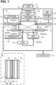
- the fuel cell system 1 includes a fuel cell 1A, a plurality of channels 20, a plurality of valves 20A, a pump 31, a pump 32, a pump 34, a filter 33, a hydrogen supply source 41, an air supply source 42, a heat exchanger 43, a power adjustment unit 44, a voltage measurement unit 51, a temperature measurement unit 52, and a controller 6.
- the plurality of channels 20 include a hydrogen supply channel 21, a hydrogen discharge channel 22, an air supply channel 23, an air discharge channel 24, and a heating medium circulation channel 25.
- the plurality of valves 20A include a hydrogen supply valve 21A, a hydrogen discharge valve 22A, an air supply valve 23A, and an air discharge valve 24A.
- the fuel cell 1A has a stacked structure in which a plurality of cells 10 are stacked.
- the adjacent cells 10 are separated from each other by a separator (not illustrated).
- the cells 10 are connected in series with each other.
- Each cell 10 includes an anode 11, a cathode 12, and an electrolyte (e.g., a solid polymer electrolyte membrane) 13.
- the electrolyte 13 is disposed between the anode 11 and the cathode 12.
- the anode 11 includes an anode electrode 11A and an anode catalyst 11B.
- the cathode 12 includes a cathode electrode 12A and a cathode catalyst 12B.
- the anode electrode 11A and the cathode electrode 12A are electrodes.
- the anode catalyst 11B and the cathode catalyst 12B are made of, for example, platinum supported on acetylene black.
- the materials for the anode catalyst 11B and the cathode catalyst 12B are not limited to the material disclosed as the example, and other materials may be used for the anode catalyst 11B and the cathode catalyst 12B.
- the separators have a plate shape and are disposed between the cells 10, respectively.
- Each separator has a fuel channel on one side and an oxidant channel on the other side.
- the fuel channel faces the anode electrode 11A of a corresponding cell 10.
- the oxidant channel faces the cathode electrode 12A of the corresponding cell 10.
- hydrogen is used as the fuel
- air is used as the oxidant.
- the hydrogen supply source 41 is a hydrogen inlet and functions as a supply source of hydrogen to be consumed in the fuel cell 1A.
- the hydrogen supply source 41 is connected to a hydrogen tank (not illustrated) to admit hydrogen from the hydrogen tank.
- the hydrogen supply source 41 may be connected to a water electrolysis device instead of the hydrogen tank.
- the air supply source 42 is an air inlet and functions as a supply source of air to be consumed in the fuel cell 1A.
- the air supply source 42 admits air in the atmosphere.
- the air supply source 42 may be connected to an air tank or a water electrolysis device instead.
- the hydrogen supply channel 21 and the hydrogen discharge channel 22 are pipes that allow hydrogen to flow therethrough.
- the hydrogen supply channel 21 allows hydrogen to be supplied from the hydrogen supply source 41 to the anode electrode 11A of each cell 10.
- the hydrogen discharge channel 22 allows hydrogen to be discharged from the anode electrode 11A of each cell 10.
- the air supply channel 23 and the air discharge channel 24 are pipes that allow air to flow therethrough.
- the air supply channel 23 allows air to be supplied from the air supply source 42 to the cathode electrode 12A of each cell 10.
- the air discharge channel 24 allows air to be discharged from the cathode electrode 12A of each cell 10.
- the pump 31 is disposed at the hydrogen supply channel 21.
- the pump 31 causes hydrogen to flow from the hydrogen supply source 41 toward the anode electrode 11A of each cell 10 in the hydrogen supply channel 21.
- the pump 32 is disposed at the air supply channel 23.
- the pump 32 causes air to flow from the air supply source 42 toward the cathode electrode 12A of each cell 10 in the air supply channel 23.
- the filter 33 is disposed at a particular position between the air supply source 42 and the pump 32 in the air supply channel 23. The filter 33 removes impurities from the air flowing through the air supply channel 23.
- the hydrogen supply valve 21A is disposed at the hydrogen supply channel 21.
- the hydrogen supply valve 21A is a control valve that can open and close the hydrogen supply channel 21.
- the hydrogen discharge valve 22A is disposed at the hydrogen discharge channel 22.
- the hydrogen discharge valve 22A is a control valve that can open and close the hydrogen discharge channel 22.
- the air supply valve 23A is disposed at the air supply channel 23.
- the air supply valve 23A is a control valve that can open and close the air supply channel 23.
- the air discharge valve 24A is disposed at the air discharge channel 24.
- the air discharge value 24A is a control value that can open and close the air discharge channel 24.
- the hydrogen supply valve 21A can regulate a flow rate of hydrogen flowing through the hydrogen supply channel 21.
- the air supply valve 23A can regulate a flow rate of air flowing through the air supply channel 23.
- the hydrogen supply valve 21A and the air supply valve 23A can each regulate their respective flow rates stepwise according to electric signals output from the controller 6.
- the hydrogen supply source 41, the pump 31, the hydrogen supply valve 21A, and the hydrogen supply channel 21 function as a fuel supply unit 1B that supplies hydrogen to the anode electrode 11A of the fuel cell 1A.
- the fuel supply unit 1B supplies hydrogen to the anode electrode 11A through the hydrogen supply channel 21 by driving the pump 31 and opening the hydrogen supply valve 21A.
- the fuel supply unit 1B can regulate an amount of hydrogen supplied to the anode electrode 11A stepwise by a predetermined step amount r by controlling the flow rate of hydrogen flowing through the hydrogen supply channel 21 by the hydrogen supply value 21A.
- the fuel supply unit 1B stops supplying hydrogen to the anode electrode 11A by stopping the pump 31 and closing the hydrogen supply valve 21A.
- the air supply source 42, the filter 33, the pump 32, the air supply valve 23A, and the air supply channel 23 function as an air supply unit 1C that supplies air to the cathode electrode 12A of the fuel cell 1A.
- the air supply unit 1C supplies air to the cathode electrode 12A via the air supply channel 23 by driving the pump 32 and opening the air supply value 23A.
- the air supply unit 1C can regulate an amount of air supplied to the cathode electrode 12A stepwise by a predetermined step amount q by controlling the flow rate of air flowing through the air supply channel 23 by the air supply value 23A.
- the air supply unit 1C stops supplying air to the cathode electrode 12A by stopping the pump 32 and closing the air supply valve 23A.
- a voltage is applied between output terminals 18 of the fuel cell 1A.
- the voltage is equal to a sum of voltages, each of which is a voltage between the anode electrode 11A and the cathode electrode 12A of each cell 10.
- a voltage is referred to as a "stack voltage”.
- the current outputted from the output terminals 18 of the fuel cell 1A is referred to as a "stack current”.
- the fuel cell system 1 has connection terminals 19 to which an external load Ld can be connected.
- the output terminals 18 of the fuel cell 1A are connected to the connection terminals 19 via the power adjustment unit 44.
- the power adjustment unit 44 is a converter that steps up or down the stack voltage between the output terminals 18.
- the power adjustment unit 44 controls the voltage and the current output from the connection terminals 19 to adjust the power that can be supplied to the external load Ld connected to the connection terminals 19.
- this power is referred to as "output power”.
- the voltage measurement unit 51 includes a voltage dividing resistor and an AD converter.
- the voltage dividing resistor is connected to the output terminals 18 and divides a stack voltage.
- the AD converter is connected to the voltage dividing resistor.
- the AD converter outputs am electric signal indicating a voltage between ends of the voltage dividing resistor to the controller 6.
- the heating medium circulation channel 25 is a pipe through which the heating medium circulates.
- the heating medium is a fluid for heating the fuel cell 1A.
- the heating medium circulation channel 25 has an annular shape.
- a portion of the heating medium circulation channel 25 is located within the fuel cell 1A.
- the portion of the heating medium circulation channel 25 located within the fuel cell 1A is referred to as a "heating portion 25A".
- the heating medium flowing through the heating portion 25A heats the cells 10 by supplying heat to the cells 10 of the fuel cell 1A. Further, the heating medium is cooled by supplying heat to the cells 10 in the heating portion 25A.
- a pump 34 and the heat exchanger 43 are interposed in the heating medium circulation channel 25.
- the pump 34 sends the heating medium discharged from an outlet 252 of the heating portion 25A toward the heat exchanger 43.
- the heat exchanger 43 heats the heating medium by supplying heat to the heating medium sent out by the pump 34.
- the heating medium heated by the heat exchanger 43 is sent toward an inlet 251 of the heating portion 25A.
- the temperature measurement unit 52 is connected to the heating medium circulation channel 25 at a position between the outlet 252 of the heating portion 25A and the pump 34.
- the temperature measurement unit 52 is a thermocouple.
- the temperature measurement unit 52 measures a temperature of the heating medium discharged from the outlet 252 of the heating portion 25A, and outputs an electric signal indicating the measurement result to the controller 6.
- the controller 6 is a control board included in the fuel cell system 1, and controls the entire fuel cell system 1.
- the anode electrode 11A of the anode 11 is supplied with hydrogen from the hydrogen supply source 41 through the hydrogen supply channel 21. Hydrogen is decomposed into hydrogen ions and electrons by the anode catalyst 11B of the anode 11. The hydrogen ions flow through the electrolyte 13 toward the cathode 12. The electrons flow toward the cathode electrode 12A of the cathode 12 through the output terminals 18, the connection terminals 19, and the external load Ld. Thus, the external load Ld is supplied with electric power.
- the cathode electrode 12A of the cathode 12 is supplied with air from the air supply source 42 through the air supply channel 23.
- the hydrogen ions that have flowed from the anode 11 via the electrolyte 13, the electrons that have flowed from the anode 11 via the output terminals 18, the connection terminals 19, and the external load Ld, and oxygen molecules in the air are combined at the cathode catalyst 12B of the cathode 12, thereby generating water.
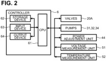
- the controller 6 includes a CPU 61, a storage device 62, an input device 63, and an output device 64.
- the CPU 61 is electrically connected to the storage device 62, the input device 63, the output device 64, the plurality of valves 20A, the pump 31, the pump 32, the pump 34, the power adjustment unit 44, the voltage measurement unit 51, and the temperature measurement unit 52.
- the CPU 61 controls the fuel cell system 1 including the controller 6.
- the storage device 62 stores programs for the CPU 61 to execute a main process (refer to FIG. 11 ), a power generation process (refer to FIG. 12 ), and an output control process (refer to FIG. 13 ), which will be described later.
- the input device 63 is a push button, and receives an input operation to the fuel cell system 1.
- the output device 64 is a display, and outputs the state of the fuel cell system 1 and other information.
- the CPU 61 controls the pump 31 to cause hydrogen to flow from the hydrogen supply source 41 toward the anode electrode 11A of each cell 10 through the hydrogen supply channel 21.
- the CPU 61 controls the pump 32 to cause air to flow from the air supply source 42 toward the cathode electrode 12A of each cell 10 through the air supply channel 23.
- the CPU 61 controls the pump 34 to cause the heating medium to circulate through the heating medium circulation channel 25.
- the heating medium heated by the heat exchanger 43 is sent toward the heating portion 25A of the heating medium circulation channel 25.
- the CPU 61 controls the plurality of valves 20A to open and close the plurality of channels 20.
- the CPU 61 can adjust an output power of the fuel cell system 1 by outputting an electric signal to and controlling the power adjustment unit 44.
- the CPU 61 can obtain a stack voltage of the fuel cell 1A based on the electric signal output from the voltage measurement unit 51.
- the CPU 61 can obtain a temperature of the heating medium discharged from the outlet 252 of the heating portion 25A of the heating medium circulation channel 25 based on a signal output from the temperature measurement unit 52.
- FIG. 3 is a graph showing changes over time in the stack voltage, the stack current of the fuel cell 1A, and the output power of the fuel cell system 1. The stack voltage and the stack current both sharply drop after the elapse of time t11 from the start of power generation, indicating that flooding has occurred at this timing.
- the fuel cell system 1 takes the following measures to reduce the occurrence of flooding: (1) heating the fuel cell 1A; (2) controlling the output power; (3) adjusting an amount of air supplied at the start of power generation; and (4) adjusting the amount of air supplied after the temperature of the heating medium rises.
- the CPU 61 drives the pump 34 disposed in the heating medium circulation channel 25 to supply the heating medium to the heating portion 25A to heat the cells 10.
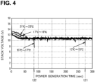
- FIG. 4 is a graph showing changes over time in the stack voltage when the threshold Tk is set from 13°C to 15°C, from 15°C to 17°C, from 17°C to 19°C, and from 21°C to 23°C, respectively.
- the threshold Tk was set to from 13°C to 15°C
- the stack voltage sharply dropped after the elapse of time t21 from the start of power generation.
- the threshold Tk was set to from 15°C to 17°C
- the stack voltage sharply dropped after the elapse of time t22 from the start of power generation. Both of these indicate that flooding has occurred at the respective timings.
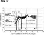
- FIG. 5 is a graph showing a relationship between the stack current and the temperature of the heating medium measured by the temperature measurement unit 52 for each case when the threshold Tk is set from 17°C to 19°C (ambient temperature 9°C/14°C), from 20°C to 22°C, from 21°C to 23°C, from 22°C to 24°C, and from 24°C to 26°C, respectively.
- the temperature of the heating medium increases as the elapsed time from the start of power generation of the fuel cell 1A becomes longer. Therefore, the horizontal axis (heating medium temperature) of the graph can be regarded as synonymous with the elapsed time from the start of power generation of the fuel cell 1A.
- FIG. 6 is a graph showing changes over time in the stack voltage when the threshold Vh1 is set to 0.60V, 0.63V, 0.64V, and 0.66V per cell, respectively.
- the threshold Vh1 was set to 0.60V per cell
- the stack voltage sharply dropped after the elapse of time t41 from the start of power generation.
- the threshold Vh1 was set to 0.63V per cell
- the stack voltage sharply dropped after the elapse of time t42 from the start of power generation.
- the threshold Vh1 was set to 0.64V per cell
- the stack voltage sharply dropped after the elapse of time t43 from the start of power generation.
- a rapid drop in the stack voltage is not shown due to the issue of the sampling period.
- the threshold Vh1 is set to 0.66V per cell and the threshold Vh2 is set to 0.68 V per cell, which is greater than the threshold Vh1. Further, the CPU 61 controls the output power based on the set thresholds Vh1 and Vh2.
- the degree of increasing the output power when the voltage of each cell 10 is reaches or exceeds the threshold Vh2 flooding is more likely to occur due to the rapid increase in stack current.
- the degree of increasing the output power is referred to as an "increase amount Wu”.
- FIG. 7 is a graph showing a relationship between the stack current and the temperature of the heating medium measured by the temperature measurement unit 52 for each case where the increase amount Wu of the output power is set to 1 W/2 sec, 2 W/2 sec, and 5 W/2 sec, respectively.
- the horizontal axis (heating medium temperature) of the graph can be regarded as synonymous with the elapsed time from the start of power generation of the fuel cell 1A.
- the increase amount Wu is set, the more the timing of the stack current starting to flow is delayed, and a rapid increase in the stack current can be prevented (an arrow Y12). This means that setting a lower increase amount Wu can effectively prevent a large stack current from flowing due to the fuel cell 1A generating power at a low temperature. Therefore, it was found that setting a lower increase amount Wu allows the fuel cell 1A to generate power in an environment where flooding is less likely to occur. In the present embodiment, the increase amount Wu is set to 1 W.
- the CPU 61 sets the air supply amount to twice the supply amount of air required for normal power generation from immediately before the start of power generation of the fuel cell 1A until the temperature of the heating medium measured by the temperature measurement unit 52 reaches or exceeds the predetermined threshold Th.
- the air supply amount required for normal power generation is referred to as a "second supply amount Q2", and a supply amount twice the second supply amount is referred to as a "first supply amount Q1".
- the threshold Th is set to 37.5°C.
- FIG. 8 is a graph showing changes over time in the stack voltage and the output power when the air supply amount is adjusted as described above.
- the temperature of the heating medium measured by the temperature measurement unit 52 gradually rises from 32.9°C until time t62 elapses from the start of power generation. Then, when time t62 elapses, the temperature of the heating medium measured by the temperature measurement unit 52 reaches the threshold Th.
- the CPU 61 control the air supply amount such that the amount of the air supplied to the cathode electrode 12A of each cell 10 by the air supply unit 1C is sharply reduced from the first supply amount Q1 to the second supply amount Q2.
- the stack voltage temporarily drops to 9.55 V (refer to sample P1) due to the sudden decrease in the air supply amount. Temporarily dropping of the stack voltage to 9.55 V causes the output power from the fuel cell system 1 to become unstable, which is not preferable.
- the CPU 61 gradually reduces the air supply amount from the first supply amount Q1 to the second supply amount Q2.
- the temperature of the heating medium measured by the temperature measurement unit 52 reaches the threshold Th.
- the amount of the air supplied to the cathode electrode 12A of each cell 10 is gradually reduced from the first supply amount Q1 to the second supply amount Q2 during the period from the start of power generation to the elapse of time t72.
- the stack voltage temporarily drops to 10.2 V (refer to sample P2) due to the sudden decrease in the air supply amount.
- This value of 10.2 V is larger than the stack voltage in the case of FIG. 8 (9.55 V of the sample P1). Therefore, it was found that gradually reducing the air supply amount can stabilize the output power of the fuel cell system 1 as compared with the case of FIG. 8 .
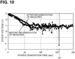
- FIG. 10 is a graph showing changes over time in the stack voltage before and after the implementation of measures (1) to (4).
- the stack voltage sharply drops after the elapse of time t81 from the start of power generation, indicating that flooding has occurred at this timing.
- a rapid drop in the stack voltage was not observed, and the stack voltage stably changed. Therefore, it was found that implementing the the measures (1) to (4) can reduce the occurrence of flooding.
- the CPU 61 starts the main process by reading and executing the program stored in the storage device 62.
- the supply of hydrogen to the anode electrodes 11A is stopped, and the supply of air to the cathode electrodes 12A is also stopped.
- the power adjustment unit 44 sets the output power of the fuel cell system 1 to 0 W.
- the external load Ld is connected to the connection terminals 19 of the fuel cell system 1.
- the CPU 61 determines whether an input operation for starting power generation of the fuel cell 1A has been detected via the input device 63 (S11). In a case where the input operation has not been detected (S11:NO), the CPU 61 returns the process to S11, and continuously waits for the input operation. In a case where the input operation for starting power generation of the fuel cell 1A has been detected via the input device 63 (S11:YES), the CPU 61 moves the process to S13.
- the CPU 61 controls the pump 31 and the hydrogen supply valve 21A of the fuel supply unit 1B to start supplying hydrogen to the anode electrodes 11A.
- the CPU 61 controls the hydrogen supply valve 21A so that the hydrogen supply amount is equal to an initial supply amount Ri.
- the initial supply amount Ri refers to an amount of hydrogen required to start power generation of the fuel cell 1A in accordance with S15 described later, and also required to fill the fuel cell 1A with hydrogen.
- the initial supply amount Ri also refers to an amount capable of blowing off and removing moisture accumulating on the anode electrodes 11A. To be specific, the initial supply amount Ri is 1 Normal Liter per purge (1 NL/purge).
- the CPU 61 controls the pump 32 and the air supply value 23A of the air supply unit 1C to start supplying air to the cathode electrodes 12A (S13).
- the CPU 61 controls the air supply valve 23A so that the air supply amount is equal to an initial supply amount Qi.
- the initial supply amount Qi refers to an amount of the air required to start power generation of the fuel cell 1A in accordance with S15 described later, and also required to fill the fuel cell 1A with air.
- the initial supply amount Qi also refers to an amount capable of blowing off and removing moisture accumulating on the cathode electrodes 12A.
- the fuel cell 1A starts power generation in response to the hydrogen supply to the anode electrodes 11A from the fuel supply unit 1B and the air supply to the cathode electrodes 12A from the air supply unit 1C.
- a stack voltage is applied between the output terminals 18 of the fuel cell 1A.
- the CPU 61 controls the power adjustment unit 44 to change the output power of the fuel cell system 1 from 0 W to an initial power Wi (S15). Thus, the power supply to the external load Ld connected to the connection terminals 19 of the fuel cell system 1 is started.
- the CPU 61 starts the power generation process (refer to FIG. 12 ) (S17), and then starts the output control process (S19).
- the power generation process and the output control process are executed in parallel with the main process.
- the CPU 61 determines whether an input operation for ending power generation of the fuel cell 1A has been detected via the input device 63 (S21). In a case where the input operation has not been detected (S21:NO), the CPU 61 returns the process to S21. During this time, the power generation process and the output control process are continued.
- the CPU 61 controls the hydrogen supply valve 21A so that the amount of hydrogen supplied to the anode electrodes 11A is equal to a hydrogen supply amount for power generation Rv in a state where the fuel cell 1A generates power (S41).
- the hydrogen supply amount for power generation Rv refers to a hydrogen supply amount required for normal power generation.
- the hydrogen supply amount for power generation Rv is greater than or equal to the initial supply amount Ri (Rv ⁇ Ri).
- the CPU 61 controls the air supply valve 23A so that the amount of air supplied to the cathode electrodes 12A is equal to the first supply amount Q1 (S41).
- the first supply amount Q1 is substantially equal to the initial supply amount Qi.
- the CPU 61 receives the temperature of the heating medium measured by the temperature measurement unit 52. The CPU 61 determines whether the received temperature is greater than or equal to the threshold Th (S43). If the CPU 61 determines that the temperature of the heating medium is less than the threshold Th (S43:NO), the CPU 61 returns the process to S41. The CPU 61 continues to control the hydrogen supply valve 21A so that the amount of the hydrogen supplied to the anode electrodes 11A is equal to the hydrogen supply amount for power generation Rv (S41). Further, the CPU 61 controls the air supply valve 23A so that the amount of the air supplied to the cathode electrodes 12A is equal to the first supply amount Q1 (S41).
- the CPU 61 determines that the temperature of the heating medium is greater than or equal to the threshold Th (S43:YES), the CPU 61 returns the process to S45.
- the CPU 61 controls the air supply value 23A to gradually reduce the amount of the air supplied to the cathode electrodes 12A from the first supply amount Q1 to the second supply amount Q2 by a step amount q every second (S45).
- the second supply amount Q2 is half of the first supply amount Q1. That is, the amount of the air supplied to the cathode electrodes 12A is gradually reduced, thereby eventually becoming half of the first supply amount Q1.
- the CPU 61 receives the temperature of the heating medium measured by the temperature measurement unit 52. The CPU 61 determines whether the received temperature of the heating medium is greater than or equal to the threshold Th (S47). If the CPU 61 determines that the temperature of the heating medium is equal to or greater than the threshold Th (S47:YES), the CPU 61 continues to control the hydrogen supply valve 21A so that the amount of the hydrogen supplied to the anode electrodes 11A is equal to the hydrogen supply amount for power generation Rv (S49). Further, the CPU 61 continues to control the air supply valve 23A so that the amount of the air supplied to the cathode electrodes 12A is equal to the second supply amount Q2 (S49).
- the CPU 61 determines that the temperature of the heating medium is less than the threshold Th (S47:NO) after the amount of air supplied to the cathode electrodes 12A is reduced to the second supply amount Q2, the CPU 61 returns the process to S41.
- the CPU 61 continues to control the hydrogen supply valve 21A so that the amount of the hydrogen supplied to the anode electrodes 11A is equal to the hydrogen supply amount for power generation Rv (S41). Further, the CPU 61 controls the air supply valve 23A so that the amount of the air supplied to the cathode electrodes 12A is equal to the first supply amount Q1 (S41). Thus, the amount of air supplied to the cathode electrodes 12A increases to twice the second amount Q2.
- the CPU 61 receives the stack voltage measured by the voltage measurement unit 51. Based on the received stack voltage, the CPU 61 identifies a voltage per each of the plurality of cells 10 (hereinafter, referred to as a "cell voltage). The CPU 61 determines whether the identified cell voltage is less than the threshold Vh1 (S61). If the CPU 61 determines that the cell voltage is less than the threshold Vh1 (S61:YES), the CPU 61 controls the power adjustment unit 44 so that the output power is equal to a value obtained by subtracting a predetermined power (hereinafter, referred to as a "reduction amount Wd" from the current output power (S63). In the present embodiment, the reduction amount Wd is 10 W. The CPU 61 moves the process to S69.
- the CPU 61 determines whether the identified cell voltage is greater than or equal to the threshold Vh1 (S61:NO). If the CPU 61 determines that the identified cell voltage is greater than or equal to the threshold Vh2 (S65:YES), the CPU 61 controls the power adjustment unit 44 so that the output power is equal to a value obtained by adding an increase amount Wu to the current output power (S67). Since the increase amount Wu is set to 1 W in the present embodiment, the increase amount Wu is one-tenth of the reduction amount Wd (10 W). The CPU 61 moves the process to S69.
- the CPU 61 determines that the identified cell voltage is less than the threshold Vh2 (S65:NO), the CPU 61 moves the process to S69 without changing the output current.
- the CPU 61 determines whether two seconds have elapsed from completion of the processing of S61 to S67 (S69). If the CPU 61 determines that two seconds have not elapsed from the completion of the processing of S61 to S67 (S69:NO), the CPU61 moves the process back to S69. If the CPU 61 determines that two seconds have elapsed from the completion of the processing of S61 to S67 (S69:YES), the CPU 61 moves the process back to S61.
- the CPU 61 detects an input operation for ending the power generation by the fuel cell 1A (S21:YES), the CPU 61 ends the power generation process started in S17 (S23), and ends the output control process started in S19 (S25).
- the CPU 61 controls the power adjustment unit 44 to change the output power of the fuel cell system 1 to 0 W (S27). Thus, the power supply to the external load Ld connected to the connection terminals 19 of the fuel cell system 1 is stopped.
- the CPU 61 controls the pump 31 and the hydrogen supply valve 21A of the fuel supply unit 1B to stop supplying hydrogen to the anode electrodes 11A (S29).
- the CPU 61 controls the pump 32 and the air supply value 23A of the air supply unit 1C to stop supplying air to the cathode electrodes 12A (S29). Thus, the power generation by the fuel cell 1A is stopped.
- the CPU 61 ends the main process.
- the amount of the air supplied to the cathode electrodes 12A is set to the first supply amount Q1 (S41).
- the first supply amount Q1 is twice the second supply amount Q2.
- Supplying a large amount of air to the cathode electrodes 12A allows the moisture accumulating on the cathode electrodes 12A to be blown off and removed from the cathode electrodes 12A. Therefore, in the fuel cell system 1, in the case of a low-temperature environment in which flooding is likely to occur, the occurrence of flooding can be reduced by supplying a large amount of air.
- the amount of the air supplied to the cathode electrodes 12A is gradually reduced from the first supply amount Q1 to the second supply amount Q2 (S45).
- the second supply amount Q2 is half of the first supply amount Q1.
- the air at the first supply amount Q1 is supplied to the cathode electrodes 12A in S41. That is, immediately after the start of the power generation by the fuel cell 1A, the air at the first supply amount Q1 is supplied to the cathode electrodes 12A regardless of the temperature of the heating medium.
- the moisture accumulating on the cathode electrodes 12A at the start of power generation by the fuel cell 1A can be blown off and removed from the cathode electrodes 12A with air.
- the occurrence of flooding and the resulting reduction in power generation efficiency due to moisture accumulating on the cathode electrodes 12A can be prevented from the start of power generation by the fuel cell 1A.
- the air supply value 23A of the air supply unit 1C gradually reduces the amount of the air supplied to the cathode electrodes 12A to the second supply amount Q2 by the step amount q every second.
- the control of the air supply amount can be performed accurately with a simple configuration.
- the time change of the supply amount of air to the cathode electrodes 12A can be maintained constant.
- the output power is reduced by the reduction amount Wd (S63).
- the occurrence of flooding can be prevented when a large amount of power is supplied to the external load Ld while the stack voltage of the fuel cell 1A is low.
- the output power is increased by the increase amount Wu (S67).
- power can be supplied to the external load Ld by efficiently using the power generation capacity of the fuel cell 1A.
- the necessity of increasing or reducing the output power is determined based on two thresholds (thresholds Vh1 and Vh2). This can stabilize the output power when the stack voltage is greater than or equal to the threshold Vh1 and less than the threshold Vh2.
- the increase amount Wu is less than the reduction amount Wd. This can prevent the occurrence of flooding due to a sudden increase in the output power.
- the reduction amount Wd is set to be ten times the increase amount Wu. This allows the output power to rapidly reduce in a case where the stack voltage is less than the threshold Vh1. Therefore, in the fuel cell system 1, conditions where flooding is likely to occur can be promptly resolved.
- the present invention is not limited to the above-described embodiment, and various modifications are possible.
- the fuel cell 1A may generate power by being supplied with substances other than hydrogen by the fuel supply unit 1B.
- the fuel supply unit 1B may supply methanol to the fuel cell 1A for power generation.
- the temperature measurement unit 52 may measure the temperature of the heating medium flowing through the heating portion 25A.
- the fuel cell system 1 may further include a circulation channel that connects the hydrogen supply channel 21 and the hydrogen discharge channel 22.
- the circulation channel may allow a part of hydrogen discharged through the hydrogen discharge channel 22 to flow toward the hydrogen supply channel 21 to circulate hydrogen.
- the pump 31 might not necessarily be provided.
- contaminants such as dust and dirt
- contaminants such as dust and dirt
- those chemically bonded to the cathode electrodes 12A such as organic gases, NOx, and SOx
- thresholds Tk, Th, Vh1, and Vh2 in the above embodiment are merely examples, and other values may be set as appropriate.
- the amount of air to be supplied may be controlled to the first supply amount Q1.
- the amount of the air supplied by the air supply unit 1C may be gradually reduced from the initial supply amount Qi to the second supply amount Q2. That is, in the fuel cell system 1, immediately after the power generation by the fuel cell 1A starts, the amount of air supplied by the air supply unit 1C might not necessarily be set to the first supply amount Q1 at all times.
- the amount of air supplied to the cathode electrodes 12A may be gradually reduced to the second supply amount Q2 by a predetermined ratio of the first supply amount Q1. For example, 0.4% may be set as the ratio. In this case, the calculation result of Q1 ⁇ 0.004 may be calculated as an increment U.
- the amount of air supplied by the air supply source Ac may be gradually reduced from the first supply amount Q1 in increments U.
- the amount of air supplied to the cathode electrodes 12A can be gradually reduced at a constant rate. Thus, a sudden drop in the voltage of the stack due to a reduction in the supply amount of air, which can cause the stopping of power generation, can be prevented.
- the step amount q for gradually reducing the amount of air supplied to the cathode electrodes 12A from the first supply amount Q1 to the second supply amount Q2 may be variable. That is, in the fuel cell system 1, the supply amount of air may be gradually reduced by different step amounts.
- the cycle at which the supply amount of air is gradually reduced by the step amount q may be set to a value other than one second. For example, the cycle may be 2 seconds.
- the amount of air supplied to the cathode electrodes 12A may be linearly changed from the first supply amount Q1 to the second supply amount Q2. That is, the amount of air supplied to the cathode electrodes 12A might not necessarily be changed gradually.
- the cathode electrodes 12A may be performed without supplying hydrogen to the anode electrodes 11A before power generation by the fuel cell 1A starts in S13. That is, in the fuel cell system 1, before the fuel cell 1A starts power generation, air may be supplied to the cathode electrodes 12A by the air supply unit 1C to remove moisture accumulating on the cathode electrodes 12A. Thus, in the fuel cell system 1, moisture accumulating on the cathode electrodes 12A can be removed before the fuel cell 1A starts power generation. In the fuel cell system 1, the reduction in power generation efficiency due to the occurrence of flooding caused by moisture accumulating on the cathode electrodes 12A can be prevented before the fuel cell 1A starts power generation.
- a relationship between the first supply amount Q1 and the second supply amount Q2 is not limited to the above embodiment.
- the first supply amount Q1 may be changed as appropriate within a range satisfying the condition that the first supply amount Q1 is greater than the second supply amount Q2.
- the first supply amount Q1 may be 1.5 times, 3 times, or other the second supply amount Q2.
- the reduction amount Wd and the increase amount Wu of the output voltage are not limited to those in the above embodiment. Each value may be appropriately changed within a range satisfying the condition that the reduction amount Wd is greater than the increase amount Wu. In one example, the reduction amount Wd may be greater than 10 times the increase amount Wu. In another example, the reduction amount Wd may be set to 10 W, and the increase amount Wu may be set to 5 W. The reduction amount Wd may be less than the increase amount Wu.
- the fuel cell system 1 might not necessarily execute the output control process.
- the CPU 61 that executes S17 is an example of a "power generation process” in the present invention.
- the CPU 61 that executes S41 is an example of a "first supply process” or a “startup supply process” in the present invention.
- the CPU 61 that executes S45 and S49 is an example of a "second supply process” in the present invention.
- the CPU 61 that executes S45 is an example of a "stepwise supply process” in the present invention.
- the CPU 61 that executes S49 is an example of a "continuous supply process” in the present invention.
- the CPU 61 that executes S13 is an example of a "pre-power generation supply process” in the present invention.
- the CPU 61 that executes S63 is an example of a "power reduction process” in the present invention.
- the CPU 61 that executes S67 is an example of a "power increasing process” in the present invention.
- the threshold Th is an example of a “threshold temperature” in the present invention.
- the threshold Vh1 is an example of a “first threshold” in the present invention.
- the threshold Vh2 is an example of a "second threshold” in the present invention.
Landscapes
- Life Sciences & Earth Sciences (AREA)
- Engineering & Computer Science (AREA)
- Manufacturing & Machinery (AREA)
- Sustainable Development (AREA)
- Sustainable Energy (AREA)
- Chemical & Material Sciences (AREA)
- Chemical Kinetics & Catalysis (AREA)
- Electrochemistry (AREA)
- General Chemical & Material Sciences (AREA)
- Fuel Cell (AREA)
Abstract
Description
- The present invention relates to a fuel cell system.
-
Patent Literature 1 discloses a fuel cell system. The fuel cell system includes a cell stack, an air pump, a cell stack temperature sensor, and a CPU. The air pump supplies air to the cell stack. The cell stack temperature sensor detects a temperature of the cell stack. The CPU controls output of the air pump based on the temperature of the cell stack detected by the cell stack temperature sensor. The CPU sets air output by the air pump to be greater than output in a case where the temperature of the cell stack is greater than or equal to a predetermined temperature, during at least a part of a period until the temperature of the cell stack reaches the predetermined temperature after the cell stack starts power generation. Thus, in the fuel cell system, a time required for the fuel cell to increase its temperature is shortened. - [Patent Literature 1]
JP2011-96553A - In a case where an amount of air supplied to the cell stack is returned from a high supply state, if the supply amount is sharply reduced, there is a problem that voltage of the cell stack suddenly drops, causing power generation to suddenly stop.
- An object of the present invention is to provide a fuel cell system that can reduce an amount of air supplied to a cell stack while maintaining power generation performance of the cell stack.
- A fuel cell system according to the present invention includes a stack including at least one cell including an anode electrode, a cathode electrode, and a catalyst; a fuel supply unit configured to supply fuel to the anode electrode; an air supply unit configured to supply air to the cathode electrode; a measurement unit configured to measure a temperature of a heating medium used for controlling a temperature of the cell; and a controller configured to control the fuel supply unit and the air supply unit. The controller is configured to execute: a power generation process for causing the stack to generate power by controlling the fuel supply unit to supply the fuel to the anode electrode and controlling the air supply unit to supply the air to the cathode electrode; in response to the temperature of the heating medium measured by the measurement unit being less than a predetermined threshold temperature during power generation by the stack in the power generation process, a first supply process for supplying the air of a first supply amount to the cathode electrode by controlling the air supply unit; and in response to the temperature of the heating medium measured by the measurement unit being greater than or equal to the predetermined threshold temperature during power generation by the stack in the power generation process, a second supply process for adjusting an amount of the air supplied to the cathode electrode by controlling the air supply unit. The second supply process includes: a stepwise supply process for gradually decreasing the amount of the air supplied to the cathode electrode to a second supply amount, the second supply amount being less than the first supply amount in response to the amount of the air supplied to the cathode electrode being equal to the first supply amount; and a continuous supply process for continuously supplying the air at the second supply amount to the cathode electrode in response to the amount of the air supplied to the cathode electrode being equal to the second supply amount.
- In the fuel cell system according to the present invention, the amount of the air supplied to the cathode electrode is gradually reduced to the second supply amount. Thus, in the fuel cell system, a sudden drop in the voltage of the stack due to a reduction in the air supply amount, which may cause stopping of power generation, can be prevented.
-
- [
FIG. 1] FIG. 1 is a diagram illustrating an overview of a fuel cell system. - [
FIG. 2] FIG. 2 is a block diagram illustrating an electrical configuration of acontroller 6. - [
FIG. 3] FIG. 3 is a graph showing changes over time in a stack voltage, a stack current, and an output power. - [
FIG. 4] FIG. 4 is a graph showing changes over time in the stack voltage when a threshold Th is set to specific values, respectively. - [
FIG. 5] FIG. 5 is a graph showing a relationship between the stack current and a temperature of a heating medium measured by atemperature measurement unit 52. - [
FIG. 6] FIG. 6 is a graph showing changes over time in the stack voltage when a threshold Vh1 is set to specific values, respectively. - [
FIG. 7] FIG. 7 is a graph showing a relationship between the stack current and the temperature of the heating medium measured by thetemperature measurement unit 52. - [
FIG. 8] FIG. 8 is a graph showing changes over time in the stack voltage and the output power in a case where an air supply amount is sharply reduced. - [
FIG. 9] FIG. 9 is a graph showing changes over time in the stack voltage and the output power in a case where the air supply amount is gradually reduced. - [
FIG. 10] FIG. 10 is a graph showing changes over time in the stack voltage before and after implementation of measures. - [
FIG. 11] FIG. 11 is a flow chart of a main process. - [
FIG. 12] FIG. 12 is a flowchart of a power generation process. - [
FIG. 13] FIG. 13 is a flowchart of an output control process. - An embodiment of a
fuel cell system 1 according to the present invention will be described with reference to the drawings. The drawings to be referred to are used for describing technical features that can be adopted by the present invention, and the configurations and the like of the devices described herein are not intended to be limited thereto, but are merely examples for description. - Referring to
FIG. 1 , a description will be provided on an overview of afuel cell system 1. Thefuel cell system 1 includes afuel cell 1A, a plurality ofchannels 20, a plurality ofvalves 20A, apump 31, apump 32, apump 34, afilter 33, ahydrogen supply source 41, anair supply source 42, aheat exchanger 43, apower adjustment unit 44, avoltage measurement unit 51, atemperature measurement unit 52, and acontroller 6. The plurality ofchannels 20 include ahydrogen supply channel 21, ahydrogen discharge channel 22, anair supply channel 23, anair discharge channel 24, and a heatingmedium circulation channel 25. The plurality ofvalves 20A include ahydrogen supply valve 21A, ahydrogen discharge valve 22A, anair supply valve 23A, and anair discharge valve 24A. - The
fuel cell 1A has a stacked structure in which a plurality ofcells 10 are stacked. Theadjacent cells 10 are separated from each other by a separator (not illustrated). Thecells 10 are connected in series with each other. Eachcell 10 includes ananode 11, acathode 12, and an electrolyte (e.g., a solid polymer electrolyte membrane) 13. - The
electrolyte 13 is disposed between theanode 11 and thecathode 12. Theanode 11 includes ananode electrode 11A and an anode catalyst 11B. Thecathode 12 includes acathode electrode 12A and a cathode catalyst 12B. Theanode electrode 11A and thecathode electrode 12A are electrodes. The anode catalyst 11B and the cathode catalyst 12B are made of, for example, platinum supported on acetylene black. The materials for the anode catalyst 11B and the cathode catalyst 12B are not limited to the material disclosed as the example, and other materials may be used for the anode catalyst 11B and the cathode catalyst 12B. The separators have a plate shape and are disposed between thecells 10, respectively. Each separator has a fuel channel on one side and an oxidant channel on the other side. The fuel channel faces theanode electrode 11A of acorresponding cell 10. The oxidant channel faces thecathode electrode 12A of thecorresponding cell 10. In the present embodiment, hydrogen is used as the fuel, and air is used as the oxidant. - The
hydrogen supply source 41 is a hydrogen inlet and functions as a supply source of hydrogen to be consumed in thefuel cell 1A. For example, thehydrogen supply source 41 is connected to a hydrogen tank (not illustrated) to admit hydrogen from the hydrogen tank. Thehydrogen supply source 41 may be connected to a water electrolysis device instead of the hydrogen tank. Theair supply source 42 is an air inlet and functions as a supply source of air to be consumed in thefuel cell 1A. For example, theair supply source 42 admits air in the atmosphere. Theair supply source 42 may be connected to an air tank or a water electrolysis device instead. - The
hydrogen supply channel 21 and thehydrogen discharge channel 22 are pipes that allow hydrogen to flow therethrough. Thehydrogen supply channel 21 allows hydrogen to be supplied from thehydrogen supply source 41 to theanode electrode 11A of eachcell 10. Thehydrogen discharge channel 22 allows hydrogen to be discharged from theanode electrode 11A of eachcell 10. Theair supply channel 23 and theair discharge channel 24 are pipes that allow air to flow therethrough. Theair supply channel 23 allows air to be supplied from theair supply source 42 to thecathode electrode 12A of eachcell 10. Theair discharge channel 24 allows air to be discharged from thecathode electrode 12A of eachcell 10. - The
pump 31 is disposed at thehydrogen supply channel 21. Thepump 31 causes hydrogen to flow from thehydrogen supply source 41 toward theanode electrode 11A of eachcell 10 in thehydrogen supply channel 21. Thepump 32 is disposed at theair supply channel 23. Thepump 32 causes air to flow from theair supply source 42 toward thecathode electrode 12A of eachcell 10 in theair supply channel 23. Thefilter 33 is disposed at a particular position between theair supply source 42 and thepump 32 in theair supply channel 23. Thefilter 33 removes impurities from the air flowing through theair supply channel 23. - The
hydrogen supply valve 21A is disposed at thehydrogen supply channel 21. Thehydrogen supply valve 21A is a control valve that can open and close thehydrogen supply channel 21. Thehydrogen discharge valve 22A is disposed at thehydrogen discharge channel 22. Thehydrogen discharge valve 22A is a control valve that can open and close thehydrogen discharge channel 22. Theair supply valve 23A is disposed at theair supply channel 23. Theair supply valve 23A is a control valve that can open and close theair supply channel 23. Theair discharge valve 24A is disposed at theair discharge channel 24. Theair discharge value 24A is a control value that can open and close theair discharge channel 24. - The
hydrogen supply valve 21A can regulate a flow rate of hydrogen flowing through thehydrogen supply channel 21. Theair supply valve 23A can regulate a flow rate of air flowing through theair supply channel 23. Thehydrogen supply valve 21A and theair supply valve 23A can each regulate their respective flow rates stepwise according to electric signals output from thecontroller 6. - The
hydrogen supply source 41, thepump 31, thehydrogen supply valve 21A, and thehydrogen supply channel 21 function as afuel supply unit 1B that supplies hydrogen to theanode electrode 11A of thefuel cell 1A. Thefuel supply unit 1B supplies hydrogen to theanode electrode 11A through thehydrogen supply channel 21 by driving thepump 31 and opening thehydrogen supply valve 21A. Thefuel supply unit 1B can regulate an amount of hydrogen supplied to theanode electrode 11A stepwise by a predetermined step amount r by controlling the flow rate of hydrogen flowing through thehydrogen supply channel 21 by thehydrogen supply value 21A. Thefuel supply unit 1B stops supplying hydrogen to theanode electrode 11A by stopping thepump 31 and closing thehydrogen supply valve 21A. - The
air supply source 42, thefilter 33, thepump 32, theair supply valve 23A, and theair supply channel 23 function as anair supply unit 1C that supplies air to thecathode electrode 12A of thefuel cell 1A. Theair supply unit 1C supplies air to thecathode electrode 12A via theair supply channel 23 by driving thepump 32 and opening theair supply value 23A. Theair supply unit 1C can regulate an amount of air supplied to thecathode electrode 12A stepwise by a predetermined step amount q by controlling the flow rate of air flowing through theair supply channel 23 by theair supply value 23A. Theair supply unit 1C stops supplying air to thecathode electrode 12A by stopping thepump 32 and closing theair supply valve 23A. - In response to power generation by the
fuel cell 1A, a voltage is applied betweenoutput terminals 18 of thefuel cell 1A. The voltage is equal to a sum of voltages, each of which is a voltage between theanode electrode 11A and thecathode electrode 12A of eachcell 10. Hereinafter, such a voltage is referred to as a "stack voltage". The current outputted from theoutput terminals 18 of thefuel cell 1A is referred to as a "stack current". - The
fuel cell system 1 hasconnection terminals 19 to which an external load Ld can be connected. Theoutput terminals 18 of thefuel cell 1A are connected to theconnection terminals 19 via thepower adjustment unit 44. Thepower adjustment unit 44 is a converter that steps up or down the stack voltage between theoutput terminals 18. Thepower adjustment unit 44 controls the voltage and the current output from theconnection terminals 19 to adjust the power that can be supplied to the external load Ld connected to theconnection terminals 19. Hereinafter, this power is referred to as "output power". - The
voltage measurement unit 51 includes a voltage dividing resistor and an AD converter. The voltage dividing resistor is connected to theoutput terminals 18 and divides a stack voltage. The AD converter is connected to the voltage dividing resistor. The AD converter outputs am electric signal indicating a voltage between ends of the voltage dividing resistor to thecontroller 6. - The heating
medium circulation channel 25 is a pipe through which the heating medium circulates. The heating medium is a fluid for heating thefuel cell 1A. The heatingmedium circulation channel 25 has an annular shape. A portion of the heatingmedium circulation channel 25 is located within thefuel cell 1A. Hereinafter, the portion of the heatingmedium circulation channel 25 located within thefuel cell 1A is referred to as a "heating portion 25A". The heating medium flowing through theheating portion 25A heats thecells 10 by supplying heat to thecells 10 of thefuel cell 1A. Further, the heating medium is cooled by supplying heat to thecells 10 in theheating portion 25A. - A
pump 34 and theheat exchanger 43 are interposed in the heatingmedium circulation channel 25. Thepump 34 sends the heating medium discharged from anoutlet 252 of theheating portion 25A toward theheat exchanger 43. Theheat exchanger 43 heats the heating medium by supplying heat to the heating medium sent out by thepump 34. The heating medium heated by theheat exchanger 43 is sent toward aninlet 251 of theheating portion 25A. - The
temperature measurement unit 52 is connected to the heatingmedium circulation channel 25 at a position between theoutlet 252 of theheating portion 25A and thepump 34. Thetemperature measurement unit 52 is a thermocouple. Thetemperature measurement unit 52 measures a temperature of the heating medium discharged from theoutlet 252 of theheating portion 25A, and outputs an electric signal indicating the measurement result to thecontroller 6. - The
controller 6 is a control board included in thefuel cell system 1, and controls the entirefuel cell system 1. - In each
cell 10, theanode electrode 11A of theanode 11 is supplied with hydrogen from thehydrogen supply source 41 through thehydrogen supply channel 21. Hydrogen is decomposed into hydrogen ions and electrons by the anode catalyst 11B of theanode 11. The hydrogen ions flow through theelectrolyte 13 toward thecathode 12. The electrons flow toward thecathode electrode 12A of thecathode 12 through theoutput terminals 18, theconnection terminals 19, and the external load Ld. Thus, the external load Ld is supplied with electric power. - The
cathode electrode 12A of thecathode 12 is supplied with air from theair supply source 42 through theair supply channel 23. The hydrogen ions that have flowed from theanode 11 via theelectrolyte 13, the electrons that have flowed from theanode 11 via theoutput terminals 18, theconnection terminals 19, and the external load Ld, and oxygen molecules in the air are combined at the cathode catalyst 12B of thecathode 12, thereby generating water. - Referring to
FIG. 2 , a description will be provided on an electrical configuration of thecontroller 6. Thecontroller 6 includes aCPU 61, astorage device 62, aninput device 63, and anoutput device 64. TheCPU 61 is electrically connected to thestorage device 62, theinput device 63, theoutput device 64, the plurality ofvalves 20A, thepump 31, thepump 32, thepump 34, thepower adjustment unit 44, thevoltage measurement unit 51, and thetemperature measurement unit 52. - The
CPU 61 controls thefuel cell system 1 including thecontroller 6. Thestorage device 62 stores programs for theCPU 61 to execute a main process (refer toFIG. 11 ), a power generation process (refer toFIG. 12 ), and an output control process (refer toFIG. 13 ), which will be described later. - The
input device 63 is a push button, and receives an input operation to thefuel cell system 1. Theoutput device 64 is a display, and outputs the state of thefuel cell system 1 and other information. - The
CPU 61 controls thepump 31 to cause hydrogen to flow from thehydrogen supply source 41 toward theanode electrode 11A of eachcell 10 through thehydrogen supply channel 21. TheCPU 61 controls thepump 32 to cause air to flow from theair supply source 42 toward thecathode electrode 12A of eachcell 10 through theair supply channel 23. TheCPU 61 controls thepump 34 to cause the heating medium to circulate through the heatingmedium circulation channel 25. Thus, the heating medium heated by theheat exchanger 43 is sent toward theheating portion 25A of the heatingmedium circulation channel 25. TheCPU 61 controls the plurality ofvalves 20A to open and close the plurality ofchannels 20. - The
CPU 61 can adjust an output power of thefuel cell system 1 by outputting an electric signal to and controlling thepower adjustment unit 44. - The
CPU 61 can obtain a stack voltage of thefuel cell 1A based on the electric signal output from thevoltage measurement unit 51. TheCPU 61 can obtain a temperature of the heating medium discharged from theoutlet 252 of theheating portion 25A of the heatingmedium circulation channel 25 based on a signal output from thetemperature measurement unit 52. - Flooding refers to a phenomenon in which moisture generated in the process of power generation in the
fuel cell 1A accumulates on acathode electrode 12A. If flooding occurs, moisture accumulating on thecathode electrode 12A blocks the air pathways, resulting in a degradation in power generation performance by thefuel cell 1A.FIG. 3 is a graph showing changes over time in the stack voltage, the stack current of thefuel cell 1A, and the output power of thefuel cell system 1. The stack voltage and the stack current both sharply drop after the elapse of time t11 from the start of power generation, indicating that flooding has occurred at this timing. - In the present embodiment, the
fuel cell system 1 takes the following measures to reduce the occurrence of flooding: (1) heating thefuel cell 1A; (2) controlling the output power; (3) adjusting an amount of air supplied at the start of power generation; and (4) adjusting the amount of air supplied after the temperature of the heating medium rises. - Flooding is more likely to occur as the temperature of the
fuel cell 1A during power generation is lower. This is because the lower the temperature, the more easily the moisture condenses and accumulates on acathode electrode 12A. Therefore, in response to the temperature of the heating medium measured by thetemperature measurement unit 52 falling below a predetermined threshold Tk, theCPU 61 drives thepump 34 disposed in the heatingmedium circulation channel 25 to supply the heating medium to theheating portion 25A to heat thecells 10. -
FIG. 4 is a graph showing changes over time in the stack voltage when the threshold Tk is set from 13°C to 15°C, from 15°C to 17°C, from 17°C to 19°C, and from 21°C to 23°C, respectively. When the threshold Tk was set to from 13°C to 15°C, the stack voltage sharply dropped after the elapse of time t21 from the start of power generation. When the threshold Tk was set to from 15°C to 17°C, the stack voltage sharply dropped after the elapse of time t22 from the start of power generation. Both of these indicate that flooding has occurred at the respective timings. On the other hand, when the threshold Tk was set to from 17°C to 19°C and from 21°C to 23°C, respectively, a rapid drop in the stack voltage due to the occurrence of flooding was not observed. Therefore, in the present embodiment, the threshold Tk is set to 17°C. Further, theCPU 61 performs control to heat thefuel cell 1A based on the set threshold Tk. -
FIG. 5 is a graph showing a relationship between the stack current and the temperature of the heating medium measured by thetemperature measurement unit 52 for each case when the threshold Tk is set from 17°C to 19°C (ambient temperature 9°C/14°C), from 20°C to 22°C, from 21°C to 23°C, from 22°C to 24°C, and from 24°C to 26°C, respectively. The temperature of the heating medium increases as the elapsed time from the start of power generation of thefuel cell 1A becomes longer. Therefore, the horizontal axis (heating medium temperature) of the graph can be regarded as synonymous with the elapsed time from the start of power generation of thefuel cell 1A. - From these results, it was found that the greater the threshold Tk is set, the more the timing of the stack current starting to flow is delayed, and a rapid rise in the stack current can be prevented (an arrow Y11). This means that setting a greater threshold Tk can more effectively prevent a large stack current from flowing due to the
fuel cell 1A generating power at a low temperature. Therefore, it was found that setting a greater threshold Tk allows thefuel cell 1A to generate power in an environment where flooding is less likely to occur. - Examples of a method of reducing the occurrence of flooding include a method of controlling power output from the
fuel cell system 1. In response to the voltage of eachcell 10 of thefuel cell 1A falling below a predetermined threshold Vh1, theCPU 61 controls thepower adjustment unit 44 to reduce the output power. On the other hand, in response to the voltage of eachcell 10 of thefuel cell 1A reaching or exceeding a predetermined threshold Vh2 that is greater than the threshold Vh1, theCPU 61 controls thepower adjustment unit 44 to increase the output power. Thus, theCPU 61 controls the voltage of eachcell 10 to ensure that the voltage does not fall below the threshold Vh1, thereby reducing the occurrence of flooding. -
FIG. 6 is a graph showing changes over time in the stack voltage when the threshold Vh1 is set to 0.60V, 0.63V, 0.64V, and 0.66V per cell, respectively. When the threshold Vh1 was set to 0.60V per cell, the stack voltage sharply dropped after the elapse of time t41 from the start of power generation. When the threshold Vh1 was set to 0.63V per cell, the stack voltage sharply dropped after the elapse of time t42 from the start of power generation. When the threshold Vh1 was set to 0.64V per cell, the stack voltage sharply dropped after the elapse of time t43 from the start of power generation. InFIG. 6 , a rapid drop in the stack voltage is not shown due to the issue of the sampling period. These all indicate that flooding has occurred at the respective timings. On the other hand, when the threshold Vh1 was set to 0.66V per cell, a rapid drop in the stack voltage due to the occurrence of flooding was not observed. Therefore, in the present embodiment, the threshold Vh1 is set to 0.66 V per cell and the threshold Vh2 is set to 0.68 V per cell, which is greater than the threshold Vh1. Further, theCPU 61 controls the output power based on the set thresholds Vh1 and Vh2. - If the degree of increasing the output power when the voltage of each
cell 10 is reaches or exceeds the threshold Vh2, flooding is more likely to occur due to the rapid increase in stack current. Hereinafter, the degree of increasing the output power is referred to as an "increase amount Wu". -
FIG. 7 is a graph showing a relationship between the stack current and the temperature of the heating medium measured by thetemperature measurement unit 52 for each case where the increase amount Wu of the output power is set to 1 W/2 sec, 2 W/2 sec, and 5 W/2 sec, respectively. As in the case ofFIG. 5 , the horizontal axis (heating medium temperature) of the graph can be regarded as synonymous with the elapsed time from the start of power generation of thefuel cell 1A. - From these results, it was found that the lower the increase amount Wu is set, the more the timing of the stack current starting to flow is delayed, and a rapid increase in the stack current can be prevented (an arrow Y12). This means that setting a lower increase amount Wu can effectively prevent a large stack current from flowing due to the
fuel cell 1A generating power at a low temperature. Therefore, it was found that setting a lower increase amount Wu allows thefuel cell 1A to generate power in an environment where flooding is less likely to occur. In the present embodiment, the increase amount Wu is set to 1 W. - For starting power generation of the
fuel cell 1A, in thefuel cell system 1, a large amount of air is supplied to thecathode electrode 12A of eachcell 10 by theair supply unit 1C to blow off moisture accumulating on thecathode electrodes 12A, thereby removing moisture from thecathode electrodes 12A. More specifically, theCPU 61 sets the air supply amount to twice the supply amount of air required for normal power generation from immediately before the start of power generation of thefuel cell 1A until the temperature of the heating medium measured by thetemperature measurement unit 52 reaches or exceeds the predetermined threshold Th. Hereinafter, the air supply amount required for normal power generation is referred to as a "second supply amount Q2", and a supply amount twice the second supply amount is referred to as a "first supply amount Q1". In the present embodiment, the threshold Th is set to 37.5°C. -
FIG. 8 is a graph showing changes over time in the stack voltage and the output power when the air supply amount is adjusted as described above. After the elapse of time t61 from the start of power generation, a state is switched to a state in which power can be supplied from theconnection terminals 19 by thepower adjustment unit 44. During the period from the start of power generation to the elapse of time t62 after the elapse of time t61, the stack voltage and the output power are stable in a state where air at the first supply amount Q1 is being supplied, and the occurrence of flooding is prevented. - As shown in
FIG. 8 , the temperature of the heating medium measured by thetemperature measurement unit 52 gradually rises from 32.9°C until time t62 elapses from the start of power generation. Then, when time t62 elapses, the temperature of the heating medium measured by thetemperature measurement unit 52 reaches the threshold Th. At this time, theCPU 61 control the air supply amount such that the amount of the air supplied to thecathode electrode 12A of eachcell 10 by theair supply unit 1C is sharply reduced from the first supply amount Q1 to the second supply amount Q2. In this case, the stack voltage temporarily drops to 9.55 V (refer to sample P1) due to the sudden decrease in the air supply amount. Temporarily dropping of the stack voltage to 9.55 V causes the output power from thefuel cell system 1 to become unstable, which is not preferable. - Therefore, the
CPU 61 gradually reduces the air supply amount from the first supply amount Q1 to the second supply amount Q2. As shown inFIG. 9 , when time t71 elapses from the start of power generation, the temperature of the heating medium measured by thetemperature measurement unit 52 reaches the threshold Th. The amount of the air supplied to thecathode electrode 12A of eachcell 10 is gradually reduced from the first supply amount Q1 to the second supply amount Q2 during the period from the start of power generation to the elapse of time t72. - In this case, the stack voltage temporarily drops to 10.2 V (refer to sample P2) due to the sudden decrease in the air supply amount. This value of 10.2 V is larger than the stack voltage in the case of
FIG. 8 (9.55 V of the sample P1). Therefore, it was found that gradually reducing the air supply amount can stabilize the output power of thefuel cell system 1 as compared with the case ofFIG. 8 . -
FIG. 10 is a graph showing changes over time in the stack voltage before and after the implementation of measures (1) to (4). In the case before implementation of the measures, the stack voltage sharply drops after the elapse of time t81 from the start of power generation, indicating that flooding has occurred at this timing. On the other hand, in the case after implementation of the measures, a rapid drop in the stack voltage was not observed, and the stack voltage stably changed. Therefore, it was found that implementing the the measures (1) to (4) can reduce the occurrence of flooding. - Referring to
FIGS. 11 to 13 , a description will be provided on the main process. In response to an operation of turning on the power of thecontroller 6, theCPU 61 starts the main process by reading and executing the program stored in thestorage device 62. At the start of the main process, the supply of hydrogen to theanode electrodes 11A is stopped, and the supply of air to thecathode electrodes 12A is also stopped. Thepower adjustment unit 44 sets the output power of thefuel cell system 1 to 0 W. The external load Ld is connected to theconnection terminals 19 of thefuel cell system 1. - As illustrated in
FIG. 11 , theCPU 61 determines whether an input operation for starting power generation of thefuel cell 1A has been detected via the input device 63 (S11). In a case where the input operation has not been detected (S11:NO), theCPU 61 returns the process to S11, and continuously waits for the input operation. In a case where the input operation for starting power generation of thefuel cell 1A has been detected via the input device 63 (S11:YES), theCPU 61 moves the process to S13. - The
CPU 61 controls thepump 31 and thehydrogen supply valve 21A of thefuel supply unit 1B to start supplying hydrogen to theanode electrodes 11A. TheCPU 61 controls thehydrogen supply valve 21A so that the hydrogen supply amount is equal to an initial supply amount Ri. The initial supply amount Ri refers to an amount of hydrogen required to start power generation of thefuel cell 1A in accordance with S15 described later, and also required to fill thefuel cell 1A with hydrogen. The initial supply amount Ri also refers to an amount capable of blowing off and removing moisture accumulating on theanode electrodes 11A. To be specific, the initial supply amount Ri is 1 Normal Liter per purge (1 NL/purge). - The
CPU 61 controls thepump 32 and theair supply value 23A of theair supply unit 1C to start supplying air to thecathode electrodes 12A (S13). TheCPU 61 controls theair supply valve 23A so that the air supply amount is equal to an initial supply amount Qi. The initial supply amount Qi refers to an amount of the air required to start power generation of thefuel cell 1A in accordance with S15 described later, and also required to fill thefuel cell 1A with air. The initial supply amount Qi also refers to an amount capable of blowing off and removing moisture accumulating on thecathode electrodes 12A. - By supplying air to the
cathode electrodes 12A, moisture accumulating on thecathode electrodes 12A is blown off and removed from thecathode electrodes 12A before the power supply from thefuel cell system 1 to the external load Ld is started. Thefuel cell 1A starts power generation in response to the hydrogen supply to theanode electrodes 11A from thefuel supply unit 1B and the air supply to thecathode electrodes 12A from theair supply unit 1C. A stack voltage is applied between theoutput terminals 18 of thefuel cell 1A. - The
CPU 61 controls thepower adjustment unit 44 to change the output power of thefuel cell system 1 from 0 W to an initial power Wi (S15). Thus, the power supply to the external load Ld connected to theconnection terminals 19 of thefuel cell system 1 is started. - The
CPU 61 starts the power generation process (refer toFIG. 12 ) (S17), and then starts the output control process (S19). The power generation process and the output control process are executed in parallel with the main process. - The
CPU 61 determines whether an input operation for ending power generation of thefuel cell 1A has been detected via the input device 63 (S21). In a case where the input operation has not been detected (S21:NO), theCPU 61 returns the process to S21. During this time, the power generation process and the output control process are continued. - Referring to
FIG. 12 , a description will be provided on the power generation process. TheCPU 61 controls thehydrogen supply valve 21A so that the amount of hydrogen supplied to theanode electrodes 11A is equal to a hydrogen supply amount for power generation Rv in a state where thefuel cell 1A generates power (S41). The hydrogen supply amount for power generation Rv refers to a hydrogen supply amount required for normal power generation. The hydrogen supply amount for power generation Rv is greater than or equal to the initial supply amount Ri (Rv ≥ Ri). Further, theCPU 61 controls theair supply valve 23A so that the amount of air supplied to thecathode electrodes 12A is equal to the first supply amount Q1 (S41). The first supply amount Q1 is substantially equal to the initial supply amount Qi. - The
CPU 61 receives the temperature of the heating medium measured by thetemperature measurement unit 52. TheCPU 61 determines whether the received temperature is greater than or equal to the threshold Th (S43). If theCPU 61 determines that the temperature of the heating medium is less than the threshold Th (S43:NO), theCPU 61 returns the process to S41. TheCPU 61 continues to control thehydrogen supply valve 21A so that the amount of the hydrogen supplied to theanode electrodes 11A is equal to the hydrogen supply amount for power generation Rv (S41). Further, theCPU 61 controls theair supply valve 23A so that the amount of the air supplied to thecathode electrodes 12A is equal to the first supply amount Q1 (S41). - As the power generation by the
fuel cell 1A continues, the temperature of thefuel cell 1A rises, and the temperature of the heating medium also rises. If theCPU 61 determines that the temperature of the heating medium is greater than or equal to the threshold Th (S43:YES), theCPU 61 returns the process to S45. TheCPU 61 controls theair supply value 23A to gradually reduce the amount of the air supplied to thecathode electrodes 12A from the first supply amount Q1 to the second supply amount Q2 by a step amount q every second (S45). The second supply amount Q2 is half of the first supply amount Q1. That is, the amount of the air supplied to thecathode electrodes 12A is gradually reduced, thereby eventually becoming half of the first supply amount Q1. - After the amount of the air supplied to the
cathode electrodes 12A is reduced to the second supply amount Q2, theCPU 61 receives the temperature of the heating medium measured by thetemperature measurement unit 52. TheCPU 61 determines whether the received temperature of the heating medium is greater than or equal to the threshold Th (S47). If theCPU 61 determines that the temperature of the heating medium is equal to or greater than the threshold Th (S47:YES), theCPU 61 continues to control thehydrogen supply valve 21A so that the amount of the hydrogen supplied to theanode electrodes 11A is equal to the hydrogen supply amount for power generation Rv (S49). Further, theCPU 61 continues to control theair supply valve 23A so that the amount of the air supplied to thecathode electrodes 12A is equal to the second supply amount Q2 (S49). - If the
CPU 61 determines that the temperature of the heating medium is less than the threshold Th (S47:NO) after the amount of air supplied to thecathode electrodes 12A is reduced to the second supply amount Q2, theCPU 61 returns the process to S41. TheCPU 61 continues to control thehydrogen supply valve 21A so that the amount of the hydrogen supplied to theanode electrodes 11A is equal to the hydrogen supply amount for power generation Rv (S41). Further, theCPU 61 controls theair supply valve 23A so that the amount of the air supplied to thecathode electrodes 12A is equal to the first supply amount Q1 (S41). Thus, the amount of air supplied to thecathode electrodes 12A increases to twice the second amount Q2. - Referring to
FIG. 13 , a description will be provided on the output control process. TheCPU 61 receives the stack voltage measured by thevoltage measurement unit 51. Based on the received stack voltage, theCPU 61 identifies a voltage per each of the plurality of cells 10 (hereinafter, referred to as a "cell voltage). TheCPU 61 determines whether the identified cell voltage is less than the threshold Vh1 (S61). If theCPU 61 determines that the cell voltage is less than the threshold Vh1 (S61:YES), theCPU 61 controls thepower adjustment unit 44 so that the output power is equal to a value obtained by subtracting a predetermined power (hereinafter, referred to as a "reduction amount Wd") from the current output power (S63). In the present embodiment, the reduction amount Wd is 10 W. TheCPU 61 moves the process to S69. - If the
CPU 61 determines that the identified cell voltage is greater than or equal to the threshold Vh1 (S61:NO), theCPU 61 determines whether the identified cell voltage is greater than or equal to the threshold Vh2 (S65). If theCPU 61 determines that the identified cell voltage is greater than or equal to the threshold Vh2 (S65:YES), theCPU 61 controls thepower adjustment unit 44 so that the output power is equal to a value obtained by adding an increase amount Wu to the current output power (S67). Since the increase amount Wu is set to 1 W in the present embodiment, the increase amount Wu is one-tenth of the reduction amount Wd (10 W). TheCPU 61 moves the process to S69. - If the
CPU 61 determines that the identified cell voltage is less than the threshold Vh2 (S65:NO), theCPU 61 moves the process to S69 without changing the output current. - The
CPU 61 determines whether two seconds have elapsed from completion of the processing of S61 to S67 (S69). If theCPU 61 determines that two seconds have not elapsed from the completion of the processing of S61 to S67 (S69:NO), the CPU61 moves the process back to S69. If theCPU 61 determines that two seconds have elapsed from the completion of the processing of S61 to S67 (S69:YES), theCPU 61 moves the process back to S61. - As illustrated in
FIG. 11 , if theCPU 61 detects an input operation for ending the power generation by thefuel cell 1A (S21:YES), theCPU 61 ends the power generation process started in S17 (S23), and ends the output control process started in S19 (S25). - The
CPU 61 controls thepower adjustment unit 44 to change the output power of thefuel cell system 1 to 0 W (S27). Thus, the power supply to the external load Ld connected to theconnection terminals 19 of thefuel cell system 1 is stopped. TheCPU 61 controls thepump 31 and thehydrogen supply valve 21A of thefuel supply unit 1B to stop supplying hydrogen to theanode electrodes 11A (S29). TheCPU 61 controls thepump 32 and theair supply value 23A of theair supply unit 1C to stop supplying air to thecathode electrodes 12A (S29). Thus, the power generation by thefuel cell 1A is stopped. TheCPU 61 ends the main process. - In the
fuel cell system 1, in a case where the temperature of the heating medium for heating thefuel cell 1A is less than the threshold Th (S43:NO) after thefuel cell 1A starts power generation, the amount of the air supplied to thecathode electrodes 12A is set to the first supply amount Q1 (S41). The first supply amount Q1 is twice the second supply amount Q2. Supplying a large amount of air to thecathode electrodes 12A allows the moisture accumulating on thecathode electrodes 12A to be blown off and removed from thecathode electrodes 12A. Therefore, in thefuel cell system 1, in the case of a low-temperature environment in which flooding is likely to occur, the occurrence of flooding can be reduced by supplying a large amount of air. - On the other hand, in a case where the temperature of the heating medium reaches or exceeds the threshold Th in a state where the amount of the air supplied to the
cathode electrodes 12A is equal to the first supply amount Q1 (S43 :YES), the amount of the air supplied to thecathode electrodes 12A is gradually reduced from the first supply amount Q1 to the second supply amount Q2 (S45). The second supply amount Q2 is half of the first supply amount Q1. Thus, in thefuel cell system 1, a sudden drop in the voltage of thefuel cell 1A due to a reduction in the air supply amount, which can cause the stopping of power generation, during the process of changing the air supply amount to the second supply amount Q2 required for normal power generation, can be prevented. - Immediately after the start of the power generation process (refer to
FIG. 12 ), the air at the first supply amount Q1 is supplied to thecathode electrodes 12A in S41. That is, immediately after the start of the power generation by thefuel cell 1A, the air at the first supply amount Q1 is supplied to thecathode electrodes 12A regardless of the temperature of the heating medium. By doing so, in thefuel cell system 1, the moisture accumulating on thecathode electrodes 12A at the start of power generation by thefuel cell 1A can be blown off and removed from thecathode electrodes 12A with air. In thefuel cell system 1, the occurrence of flooding and the resulting reduction in power generation efficiency due to moisture accumulating on thecathode electrodes 12A can be prevented from the start of power generation by thefuel cell 1A. - The
air supply value 23A of theair supply unit 1C gradually reduces the amount of the air supplied to thecathode electrodes 12A to the second supply amount Q2 by the step amount q every second. In thefuel cell system 1, by using theair supply valve 23A to change the air supply amount by the step amount q, the control of the air supply amount can be performed accurately with a simple configuration. Further, in thefuel cell system 1, by gradually reducing the supply amount of air every second, the time change of the supply amount of air to thecathode electrodes 12A can be maintained constant. Thus, in thefuel cell system 1, a sudden drop in the voltage of thefuel cell 1A due to a reduction in the supply amount of air, which can cause the stopping of power generation, can be prevented. - In the
fuel cells system 1, in a case where the stack voltage is less than the threshold Vh1 (S61:YES), the output power is reduced by the reduction amount Wd (S63). Thus, in thefuel cell system 1, the occurrence of flooding can be prevented when a large amount of power is supplied to the external load Ld while the stack voltage of thefuel cell 1A is low. In thefuel cells system 1, in a case where the stack voltage is greater than the threshold Vh2, the output power is increased by the increase amount Wu (S67). Thus, in thefuel cell system 1, power can be supplied to the external load Ld by efficiently using the power generation capacity of thefuel cell 1A. - In the
fuel cell system 1, the necessity of increasing or reducing the output power is determined based on two thresholds (thresholds Vh1 and Vh2). This can stabilize the output power when the stack voltage is greater than or equal to the threshold Vh1 and less than the threshold Vh2. Further, in thefuel cell system 1, the increase amount Wu is less than the reduction amount Wd. This can prevent the occurrence of flooding due to a sudden increase in the output power. In addition, in thefuel cell system 1, the reduction amount Wd is set to be ten times the increase amount Wu. This allows the output power to rapidly reduce in a case where the stack voltage is less than the threshold Vh1. Therefore, in thefuel cell system 1, conditions where flooding is likely to occur can be promptly resolved. - The present invention is not limited to the above-described embodiment, and various modifications are possible. The
fuel cell 1A may generate power by being supplied with substances other than hydrogen by thefuel supply unit 1B. For example, thefuel supply unit 1B may supply methanol to thefuel cell 1A for power generation. Thetemperature measurement unit 52 may measure the temperature of the heating medium flowing through theheating portion 25A. - The
fuel cell system 1 may further include a circulation channel that connects thehydrogen supply channel 21 and thehydrogen discharge channel 22. The circulation channel may allow a part of hydrogen discharged through thehydrogen discharge channel 22 to flow toward thehydrogen supply channel 21 to circulate hydrogen. In a case where the original pressure of hydrogen supplied from thehydrogen supply source 41 is sufficiently high, thepump 31 might not necessarily be provided. - In the
fuel cell system 1, contaminants (such as dust and dirt) attached to thecathode electrodes 12A, excluding those chemically bonded to thecathode electrodes 12A (such as organic gases, NOx, and SOx), may be removed by the supply of air by theair supply unit 1C. - The specific examples of the thresholds Tk, Th, Vh1, and Vh2 in the above embodiment are merely examples, and other values may be set as appropriate.
- In the
fuel cell system 1, in a case where power generation by thefuel cell 1A is started by the start of the supply of air to thecathode electrodes 12A (S13), the amount of air to be supplied may be controlled to the first supply amount Q1. - In the
fuel cell system 1, in a case where the temperature of the heating medium is greater than or equal to the threshold Th immediately after the power generation by thefuel cell 1A starts, the amount of the air supplied by theair supply unit 1C may be gradually reduced from the initial supply amount Qi to the second supply amount Q2. That is, in thefuel cell system 1, immediately after the power generation by thefuel cell 1A starts, the amount of air supplied by theair supply unit 1C might not necessarily be set to the first supply amount Q1 at all times. - In the
fuel cell system 1, in S45, the amount of air supplied to thecathode electrodes 12A may be gradually reduced to the second supply amount Q2 by a predetermined ratio of the first supply amount Q1. For example, 0.4% may be set as the ratio. In this case, the calculation result of Q1 × 0.004 may be calculated as an increment U. In thefuel cell system 1, in S45, the amount of air supplied by the air supply source Ac may be gradually reduced from the first supply amount Q1 in increments U. In thefuel cell system 1, the amount of air supplied to thecathode electrodes 12A can be gradually reduced at a constant rate. Thus, a sudden drop in the voltage of the stack due to a reduction in the supply amount of air, which can cause the stopping of power generation, can be prevented. - In the
fuel cell system 1, in S45, the step amount q for gradually reducing the amount of air supplied to thecathode electrodes 12A from the first supply amount Q1 to the second supply amount Q2 may be variable. That is, in thefuel cell system 1, the supply amount of air may be gradually reduced by different step amounts. In thefuel cell system 1, the cycle at which the supply amount of air is gradually reduced by the step amount q may be set to a value other than one second. For example, the cycle may be 2 seconds. In thefuel cell system 1, the amount of air supplied to thecathode electrodes 12A may be linearly changed from the first supply amount Q1 to the second supply amount Q2. That is, the amount of air supplied to thecathode electrodes 12A might not necessarily be changed gradually. - In the
fuel cell system 1, only the supply of air to thecathode electrodes 12A may be performed without supplying hydrogen to theanode electrodes 11A before power generation by thefuel cell 1A starts in S13. That is, in thefuel cell system 1, before thefuel cell 1A starts power generation, air may be supplied to thecathode electrodes 12A by theair supply unit 1C to remove moisture accumulating on thecathode electrodes 12A. Thus, in thefuel cell system 1, moisture accumulating on thecathode electrodes 12A can be removed before thefuel cell 1A starts power generation. In thefuel cell system 1, the reduction in power generation efficiency due to the occurrence of flooding caused by moisture accumulating on thecathode electrodes 12A can be prevented before thefuel cell 1A starts power generation. - A relationship between the first supply amount Q1 and the second supply amount Q2 is not limited to the above embodiment. The first supply amount Q1 may be changed as appropriate within a range satisfying the condition that the first supply amount Q1 is greater than the second supply amount Q2. For example, the first supply amount Q1 may be 1.5 times, 3 times, or other the second supply amount Q2.
- In the
fuel cell system 1, in the power control process, in a case where the cell voltage is greater than or equal to the threshold Vh1 (S61:NO), a process of increasing the output power may be executed regardless of the magnitude relationship between the cell voltage and the threshold Vh2. The respective values of the reduction amount Wd and the increase amount Wu of the output voltage are not limited to those in the above embodiment. Each value may be appropriately changed within a range satisfying the condition that the reduction amount Wd is greater than the increase amount Wu. In one example, the reduction amount Wd may be greater than 10 times the increase amount Wu. In another example, the reduction amount Wd may be set to 10 W, and the increase amount Wu may be set to 5 W. The reduction amount Wd may be less than the increase amount Wu. Thefuel cell system 1 might not necessarily execute the output control process. - The
CPU 61 that executes S17 is an example of a "power generation process" in the present invention. TheCPU 61 that executes S41 is an example of a "first supply process" or a "startup supply process" in the present invention. TheCPU 61 that executes S45 and S49 is an example of a "second supply process" in the present invention. TheCPU 61 that executes S45 is an example of a "stepwise supply process" in the present invention. TheCPU 61 that executes S49 is an example of a "continuous supply process" in the present invention. TheCPU 61 that executes S13 is an example of a "pre-power generation supply process" in the present invention. TheCPU 61 that executes S63 is an example of a "power reduction process" in the present invention. TheCPU 61 that executes S67 is an example of a "power increasing process" in the present invention. The threshold Th is an example of a "threshold temperature" in the present invention. The threshold Vh1 is an example of a "first threshold" in the present invention. The threshold Vh2 is an example of a "second threshold" in the present invention. -
- 1: fuel cell system
- 1A: fuel cell
- 1B: fuel supply unit
- 1C: air supply source
- 5: temperature measurement unit
- 6: controller
- 10: cell
- 11A: anode electrode
- 12A: cathode electrode
- 52: temperature measurement unit
Claims (11)
- A fuel cell system comprising:a stack including at least one cell including an anode electrode, a cathode electrode, and a catalyst;a fuel supply unit configured to supply fuel to the anode electrode;an air supply unit configured to supply air to the cathode electrode;a measurement unit configured to measure a temperature of a heating medium used for controlling a temperature of the cell; anda controller configured to control the fuel supply unit and the air supply unit,wherein the controller is configured to execute:a power generation process for causing the stack to generate power by controlling the fuel supply unit to supply the fuel to the anode electrode and controlling the air supply unit to supply the air to the cathode electrode;in response to the temperature of the heating medium measured by the measurement unit being less than a predetermined threshold temperature during power generation by the stack in the power generation process, a first supply process for supplying the air of a first supply amount to the cathode electrode by controlling the air supply unit; andin response to the temperature of the heating medium measured by the measurement unit being greater than or equal to the predetermined threshold temperature during power generation by the stack in the power generation process, a second supply process for adjusting an amount of the air supplied to the cathode electrode by controlling the air supply unit, the second supply process including:a stepwise supply process for gradually decreasing the amount of the air supplied to the cathode electrode to a second supply amount, the second supply amount being less than the first supply amount in response to the amount of the air supplied to the cathode electrode being equal to the first supply amount; anda continuous supply process for continuously supplying the air at the second supply amount to the cathode electrode in response to the amount of the air supplied to the cathode electrode being equal to the second supply amount.
- The fuel cell system according to claim 1,
wherein the controller is further configured to execute a startup supply process for supplying the air at the first supply amount to the cathode electrode at a start of power generation by the stack in the power generation process, regardless of the temperature of the heating medium measured by the measurement unit. - The fuel cell system according to claim 1,wherein the air supply unit is configured to control the amount of the air supplied to the cathode electrode by a predetermined step amount, andwherein the stepwise supply process includes gradually decreasing the amount of the air supplied to the cathode electrode to the second supply amount by the step amount.
- The fuel cell system according to claim 1,
wherein the stepwise supply process includes gradually decreasing the amount of the air supplied to the cathode electrode to the second supply amount per unit time. - The fuel cell system according to claim 1,
wherein the stepwise supply process includes gradually decreasing the amount of the air supplied to the cathode electrode to the second supply amount in increments of a predetermined ratio of the first supply amount. - The fuel cell system according to claim 1,
wherein the controller is further configured to execute a pre-power generation supply process for supplying the air to the cathode electrode by controlling the air supply unit before the stack starts power generation. - The fuel cell system according to claim 1,
wherein the first supply amount is at least twice the second supply amount. - The fuel cell system according to claim 1,
wherein the controller is further configured to execute:in response to a voltage of the stack being less than a first threshold voltage, a power reduction process for reducing power output from the stack; andin response to the voltage of the stack being greater than the first threshold voltage, a power increase process for increasing power output from the stack. - The fuel cell system according to claim 8,
wherein the power increase process includes increasing the power output from the stack in response to the voltage of the stack being equal to or greater than a second threshold voltage, the second threshold voltage being greater than the first threshold voltage. - The fuel cell system according to claim 8,
wherein a power reduction amount in the power reduction process is greater than a power increase amount in the power increase process. - The fuel cell system according to claim 10,
wherein the power reduction amount is at least ten time the power increase amount.
Applications Claiming Priority (2)
| Application Number | Priority Date | Filing Date | Title |
|---|---|---|---|
| JP2022110711A JP2024008665A (en) | 2022-07-08 | 2022-07-08 | fuel cell system |
| PCT/JP2023/009798 WO2024009567A1 (en) | 2022-07-08 | 2023-03-14 | Fuel cell system |
Publications (2)
| Publication Number | Publication Date |
|---|---|
| EP4535469A1 true EP4535469A1 (en) | 2025-04-09 |
| EP4535469A4 EP4535469A4 (en) | 2026-04-22 |
Family
ID=89452978
Family Applications (1)
| Application Number | Title | Priority Date | Filing Date |
|---|---|---|---|
| EP23835108.4A Pending EP4535469A4 (en) | 2022-07-08 | 2023-03-14 | FUEL CELL SYSTEM |
Country Status (3)
| Country | Link |
|---|---|
| EP (1) | EP4535469A4 (en) |
| JP (1) | JP2024008665A (en) |
| WO (1) | WO2024009567A1 (en) |
Family Cites Families (10)
| Publication number | Priority date | Publication date | Assignee | Title |
|---|---|---|---|---|
| US6387556B1 (en) * | 1997-11-20 | 2002-05-14 | Avista Laboratories, Inc. | Fuel cell power systems and methods of controlling a fuel cell power system |
| US6395414B1 (en) * | 2000-02-11 | 2002-05-28 | General Motors Corporation | Staged venting of fuel cell system during rapid shutdown |
| DE102004033169B4 (en) * | 2003-07-09 | 2009-01-08 | Honda Motor Co., Ltd. | Start up procedure of a fuel cell at low temperature |
| JP5431873B2 (en) | 2009-10-30 | 2014-03-05 | ヤマハ発動機株式会社 | Fuel cell system and transportation equipment including the same |
| JP5476408B2 (en) * | 2012-03-14 | 2014-04-23 | 本田技研工業株式会社 | Fuel cell system |
| EP2658021B1 (en) * | 2012-04-27 | 2014-12-17 | Hexis AG | Method and control device for controlling a fuel cell or a fuel cell stack |
| JP6390253B2 (en) * | 2014-08-06 | 2018-09-19 | 日産自動車株式会社 | Fuel cell power generation system |
| JP6442740B2 (en) * | 2014-12-02 | 2018-12-26 | ヒロセ電機株式会社 | Coaxial cable connector with outer conductor shell having discontinuities |
| JP6707406B2 (en) * | 2016-06-27 | 2020-06-10 | 三菱日立パワーシステムズ株式会社 | Fuel cell control device, control method, and power generation system |
| KR102777740B1 (en) * | 2019-05-08 | 2025-03-06 | 현대자동차주식회사 | System and method for removing water of fuel cell vehicle using impedance |
-
2022
- 2022-07-08 JP JP2022110711A patent/JP2024008665A/en active Pending
-
2023
- 2023-03-14 WO PCT/JP2023/009798 patent/WO2024009567A1/en not_active Ceased
- 2023-03-14 EP EP23835108.4A patent/EP4535469A4/en active Pending
Also Published As
| Publication number | Publication date |
|---|---|
| JP2024008665A (en) | 2024-01-19 |
| WO2024009567A1 (en) | 2024-01-11 |
| EP4535469A4 (en) | 2026-04-22 |
Similar Documents
| Publication | Publication Date | Title |
|---|---|---|
| CA2685265C (en) | Fuel cell system with insufficient anode gas detection | |
| JP6400044B2 (en) | Fuel cell system and its operation stop method | |
| CN103943871B (en) | For the selective reaction of minimum cell voltage fall off rate in fuel cell system | |
| EP1516384A2 (en) | Fuel cell stack defrosting | |
| US7880429B2 (en) | Power management method using feedback current bias for simultaneously controlling low cells and overall stack voltage | |
| US11043683B2 (en) | Fuel cell system and method for controlling the same | |
| JP2007335408A (en) | Multiple pressure rule control for minimizing rh deflection during transition | |
| JP2005302304A (en) | Fuel cell system | |
| US8231989B2 (en) | Method for improving FCS reliability after end cell heater failure | |
| JP2009117066A (en) | FUEL CELL SYSTEM AND CONTROL METHOD FOR FUEL CELL SYSTEM | |
| JP5804181B2 (en) | FUEL CELL SYSTEM AND CONTROL METHOD FOR FUEL CELL SYSTEM | |
| JP6083472B2 (en) | FUEL CELL SYSTEM AND CONTROL METHOD FOR FUEL CELL SYSTEM | |
| JP2009070576A (en) | Fuel cell system and deterioration detection device | |
| JP5304863B2 (en) | Fuel cell system | |
| JP2005285628A (en) | Fuel concentration detecting method for direct methanol fuel cell, and direct methanol fuel cell system | |
| JP4982977B2 (en) | Fuel cell system | |
| JP5407662B2 (en) | FUEL CELL SYSTEM AND CONTROL METHOD FOR FUEL CELL SYSTEM | |
| JP2010242183A (en) | Impurity concentrator | |
| JP2007115460A (en) | Fuel cell system | |
| WO2024009567A1 (en) | Fuel cell system | |
| JP2007227160A (en) | FUEL CELL SYSTEM AND FUEL CELL STACKING DETERMINATION METHOD | |
| JP5412780B2 (en) | FUEL CELL SYSTEM AND CONTROL METHOD FOR FUEL CELL SYSTEM | |
| JP4559754B2 (en) | Fuel cell system | |
| JP6927071B2 (en) | Fuel cell system | |
| TWI897123B (en) | Hydrogen purification system and control method thereof |
Legal Events
| Date | Code | Title | Description |
|---|---|---|---|
| STAA | Information on the status of an ep patent application or granted ep patent |
Free format text: STATUS: THE INTERNATIONAL PUBLICATION HAS BEEN MADE |
|
| PUAI | Public reference made under article 153(3) epc to a published international application that has entered the european phase |
Free format text: ORIGINAL CODE: 0009012 |
|
| STAA | Information on the status of an ep patent application or granted ep patent |
Free format text: STATUS: REQUEST FOR EXAMINATION WAS MADE |
|
| 17P | Request for examination filed |
Effective date: 20250102 |
|
| AK | Designated contracting states |
Kind code of ref document: A1 Designated state(s): AL AT BE BG CH CY CZ DE DK EE ES FI FR GB GR HR HU IE IS IT LI LT LU LV MC ME MK MT NL NO PL PT RO RS SE SI SK SM TR |
|
| P01 | Opt-out of the competence of the unified patent court (upc) registered |
Free format text: CASE NUMBER: APP_20677/2025 Effective date: 20250430 |
|
| DAV | Request for validation of the european patent (deleted) | ||
| DAX | Request for extension of the european patent (deleted) | ||
| A4 | Supplementary search report drawn up and despatched |
Effective date: 20260323 |
|
| RIC1 | Information provided on ipc code assigned before grant |
Ipc: H01M 8/04746 20160101AFI20260317BHEP Ipc: H01M 8/04225 20160101ALI20260317BHEP Ipc: H01M 8/043 20160101ALI20260317BHEP Ipc: H01M 8/04302 20160101ALI20260317BHEP Ipc: H01M 8/0432 20160101ALI20260317BHEP Ipc: H01M 8/04537 20160101ALI20260317BHEP Ipc: H01M 8/04858 20160101ALI20260317BHEP Ipc: H01M 8/10 20160101ALI20260317BHEP Ipc: H01M 8/04492 20160101ALI20260317BHEP |