EP4535446A1 - Electrochemical device and electronic device - Google Patents
Electrochemical device and electronic device Download PDFInfo
- Publication number
- EP4535446A1 EP4535446A1 EP22953435.9A EP22953435A EP4535446A1 EP 4535446 A1 EP4535446 A1 EP 4535446A1 EP 22953435 A EP22953435 A EP 22953435A EP 4535446 A1 EP4535446 A1 EP 4535446A1
- Authority
- EP
- European Patent Office
- Prior art keywords
- edge
- recess
- region
- electrochemical device
- distance
- Prior art date
- Legal status (The legal status is an assumption and is not a legal conclusion. Google has not performed a legal analysis and makes no representation as to the accuracy of the status listed.)
- Pending
Links
Images





Classifications
-
- H—ELECTRICITY
- H01—ELECTRIC ELEMENTS
- H01M—PROCESSES OR MEANS, e.g. BATTERIES, FOR THE DIRECT CONVERSION OF CHEMICAL ENERGY INTO ELECTRICAL ENERGY
- H01M10/00—Secondary cells; Manufacture thereof
- H01M10/05—Accumulators with non-aqueous electrolyte
- H01M10/058—Construction or manufacture
- H01M10/0587—Construction or manufacture of accumulators having only wound construction elements, i.e. wound positive electrodes, wound negative electrodes and wound separators
-
- H—ELECTRICITY
- H01—ELECTRIC ELEMENTS
- H01M—PROCESSES OR MEANS, e.g. BATTERIES, FOR THE DIRECT CONVERSION OF CHEMICAL ENERGY INTO ELECTRICAL ENERGY
- H01M50/00—Constructional details or processes of manufacture of the non-active parts of electrochemical cells other than fuel cells, e.g. hybrid cells
- H01M50/50—Current conducting connections for cells or batteries
- H01M50/531—Electrode connections inside a battery casing
- H01M50/533—Electrode connections inside a battery casing characterised by the shape of the leads or tabs
-
- H—ELECTRICITY
- H01—ELECTRIC ELEMENTS
- H01M—PROCESSES OR MEANS, e.g. BATTERIES, FOR THE DIRECT CONVERSION OF CHEMICAL ENERGY INTO ELECTRICAL ENERGY
- H01M50/00—Constructional details or processes of manufacture of the non-active parts of electrochemical cells other than fuel cells, e.g. hybrid cells
- H01M50/50—Current conducting connections for cells or batteries
- H01M50/531—Electrode connections inside a battery casing
- H01M50/536—Electrode connections inside a battery casing characterised by the method of fixing the leads to the electrodes, e.g. by welding
-
- H—ELECTRICITY
- H01—ELECTRIC ELEMENTS
- H01M—PROCESSES OR MEANS, e.g. BATTERIES, FOR THE DIRECT CONVERSION OF CHEMICAL ENERGY INTO ELECTRICAL ENERGY
- H01M50/00—Constructional details or processes of manufacture of the non-active parts of electrochemical cells other than fuel cells, e.g. hybrid cells
- H01M50/50—Current conducting connections for cells or batteries
- H01M50/572—Means for preventing undesired use or discharge
- H01M50/584—Means for preventing undesired use or discharge for preventing incorrect connections inside or outside the batteries
- H01M50/586—Means for preventing undesired use or discharge for preventing incorrect connections inside or outside the batteries inside the batteries, e.g. incorrect connections of electrodes
-
- H—ELECTRICITY
- H01—ELECTRIC ELEMENTS
- H01M—PROCESSES OR MEANS, e.g. BATTERIES, FOR THE DIRECT CONVERSION OF CHEMICAL ENERGY INTO ELECTRICAL ENERGY
- H01M50/00—Constructional details or processes of manufacture of the non-active parts of electrochemical cells other than fuel cells, e.g. hybrid cells
- H01M50/50—Current conducting connections for cells or batteries
- H01M50/572—Means for preventing undesired use or discharge
- H01M50/584—Means for preventing undesired use or discharge for preventing incorrect connections inside or outside the batteries
- H01M50/59—Means for preventing undesired use or discharge for preventing incorrect connections inside or outside the batteries characterised by the protection means
- H01M50/595—Tapes
-
- H—ELECTRICITY
- H01—ELECTRIC ELEMENTS
- H01M—PROCESSES OR MEANS, e.g. BATTERIES, FOR THE DIRECT CONVERSION OF CHEMICAL ENERGY INTO ELECTRICAL ENERGY
- H01M10/00—Secondary cells; Manufacture thereof
- H01M10/05—Accumulators with non-aqueous electrolyte
- H01M10/052—Li-accumulators
- H01M10/0525—Rocking-chair batteries, i.e. batteries with lithium insertion or intercalation in both electrodes; Lithium-ion batteries
-
- Y—GENERAL TAGGING OF NEW TECHNOLOGICAL DEVELOPMENTS; GENERAL TAGGING OF CROSS-SECTIONAL TECHNOLOGIES SPANNING OVER SEVERAL SECTIONS OF THE IPC; TECHNICAL SUBJECTS COVERED BY FORMER USPC CROSS-REFERENCE ART COLLECTIONS [XRACs] AND DIGESTS
- Y02—TECHNOLOGIES OR APPLICATIONS FOR MITIGATION OR ADAPTATION AGAINST CLIMATE CHANGE
- Y02E—REDUCTION OF GREENHOUSE GAS [GHG] EMISSIONS, RELATED TO ENERGY GENERATION, TRANSMISSION OR DISTRIBUTION
- Y02E60/00—Enabling technologies; Technologies with a potential or indirect contribution to GHG emissions mitigation
- Y02E60/10—Energy storage using batteries
-
- Y—GENERAL TAGGING OF NEW TECHNOLOGICAL DEVELOPMENTS; GENERAL TAGGING OF CROSS-SECTIONAL TECHNOLOGIES SPANNING OVER SEVERAL SECTIONS OF THE IPC; TECHNICAL SUBJECTS COVERED BY FORMER USPC CROSS-REFERENCE ART COLLECTIONS [XRACs] AND DIGESTS
- Y02—TECHNOLOGIES OR APPLICATIONS FOR MITIGATION OR ADAPTATION AGAINST CLIMATE CHANGE
- Y02P—CLIMATE CHANGE MITIGATION TECHNOLOGIES IN THE PRODUCTION OR PROCESSING OF GOODS
- Y02P70/00—Climate change mitigation technologies in the production process for final industrial or consumer products
- Y02P70/50—Manufacturing or production processes characterised by the final manufactured product
Definitions
- This application relates to the field of energy storage technologies, and in particular, to an electrochemical device and an electronic device including such electrochemical device.
- this application proposes an electrochemical device capable of prolonging the service life.
- the position to which the external force is applied overlaps with a protrusion on a surface of the first conductive plate (such as a weld mark), the position with a larger thickness in the first electrode plate can bear part of the external force, reducing the possibility of the protrusion piercing a separator and causing a short circuit, thereby prolonging the service life of the electrochemical device.
- a thickness of the first conductive plate is less than a thickness of the first conductive material layer. Therefore, the position with a larger thickness in the first electrode plate of the first conductive plate is the first position. Therefore, in the event of mechanical abuse, if the position to which the external force is applied overlaps with the protrusion on the surface of the first conductive plate, the first position can preferentially bear part of the external force. In addition, when viewed from the first direction, the first position has a larger area than the second position, which is conducive to bearing greater external force in the event of mechanical abuse, thereby further prolonging the service life of the electrochemical device.
- the second region when viewed from the first direction, the second region fully covers the first region. Therefore, when viewed from the first direction, the protrusion of the first conductive plate can fully fall within a range of the second region, reducing the possibility of a conductive material falling off and causing a short circuit when the protrusion falls on the second conductive material layer, thereby prolonging the service life of the electrochemical device.
- the electrode assembly is a wound structure
- the first electrode plate is a positive electrode plate
- a three-dimensional coordinate system is established based on a first direction D 1 , a second direction D 2 , and a third direction D 3 perpendicular to each other.
- the first direction D 1 is a direction perpendicular to a surface of the first conductive plate 30.
- the second direction D 2 is a direction along which the first conductive plate 30 protrudes from the electrode assembly 20.
- the second direction D 2 may alternatively be a direction of the winding center axis C.
- the third direction D 3 is a direction from the first conductive plate 30 to the second conductive plate 40.
- the electrode assembly 20 may alternatively be a laminated structure.
- the first electrode plate 21 includes a first current collector 210, a first conductive material layer 211, and a second conductive material layer 212.
- the first current collector 210 includes a first surface 210a and a second surface 210b disposed opposite to each other.
- the first conductive material layer 211 is disposed on the first surface 210a.
- the second conductive material layer 212 is disposed on the second surface 210b.
- the second electrode plate 22 includes a second current collector 220, a third conductive material layer 221, and a fourth conductive material layer 222.
- the second current collector 220 includes a third surface 220a and a fourth surface 220b disposed opposite to each other.
- the third conductive material layer 221 is disposed on the third surface 220a.
- the fourth conductive material layer 222 is disposed on the fourth surface 220b.
- the second conductive material layer 212 and the fourth conductive material layer 222 face each other across the separator 23.
- the first surface 210a of the first current collector 210 is farther from the winding center axis C than the second surface 210b, and the third surface 220a of the second current collector 220 is farther from the winding center axis C than the fourth surface 220b.
- the negative electrode active material layer contains a negative electrode active material
- the negative electrode active material is a negative electrode active material known in the art that can reversibly intercalate and deintercalate active ions. This is not limited in this application.
- the negative electrode active material includes but is not limited to a combination of one or more of graphite, soft carbon, hard carbon, carbon fiber, mesocarbon microbeads, a silicon-based material, a tin-based material, lithium titanate, or another metal capable of forming an alloy with lithium.
- the graphite may be a combination of one or more selected from a group consisting of artificial graphite, natural graphite, and modified graphite.
- the first conductive material layer 211 includes a first opening 2110.
- the first surface 210a of the first current collector 210 includes a first region 2100.
- the first region 2100 is configured to be a region of the first surface 210a exposed at the first opening 2110. That is, the first region 2100 is exposed at the first opening 2110.
- the first direction D 1 may alternatively be a direction perpendicular to the first region 2100.
- the first opening 2110 is cleaned in the first conductive material layer 211 through a laser cleaning manner, so that the first region 2100 is exposed.
- At least one depression 210c is correspondingly formed on the second surface 210b of the first current collector 210.
- the protrusions 30a and 30b and the depression 210c may be formed during the welding process (which may be referred to as weld marks in this case). However, this is not limited in this application.
- at least one depression 30c may also be formed at the welding position between the first conductive plate 30 and the first region 2100.
- a plurality of depressions 30c arranged in a matrix may be formed at the welding position between the first conductive plate 30 and the first region 2100. The depression 30c is recessed from the first region 2100 to the first conductive plate 30.
- this part of the first conductive material layer 211 present between the first opening 2110 and the first recess 2130 can increase the height in the first direction D 1 , and the presence of this part of the first conductive material layer 211 reduces the height difference in the first direction D 1 with a weld mark (such as the protrusion 30b), and even this part of the first conductive material layer 211 may be higher than the weld mark in the first direction D 1 .
- the second opening 2120 is a three-dimensional structure, but when viewed from the first direction D 1 , the second opening 2120 includes a plurality of edges connected sequentially (not shown in the figure). When viewed from the first direction D 1 , the third edge 2105, the fourth edge 2106, the seventh edge 2107, and the eighth edge 2108 of the second region 2100' respectively overlap with a plurality of edges of the second opening 2120.
- the second electrode plate 22 can alternatively adopt a design similar to that of the first electrode plate 21.
- a third region for example, a blank region
- the second electrode plate 22 is provided with a second recess at an end edge, and the third conductive material layer 221 corresponds to the third region being the blank region and is spaced apart from the first recess 2130 in the second direction D 2 .
- this can further improve the space utilization and prolong the service life of the electrochemical device 100.
- a thickness of the first conductive plate 30 is less than a thickness of the first conductive material layer 211. Therefore, after the first conductive plate 30 is connected to the first region 2100, the position with a larger thickness in the first electrode plate 21 having the first conductive plate 30 is the position of the first electrode plate 21 with a double-sided coating on both sides of the first region 2100 in the third direction D 3 , that is, the first position P 1 . Therefore, in the event of mechanical abuse, if the position to which the external force is applied overlaps with the weld mark of the first conductive plate 30, the first position P 1 can preferentially bear part of the external force. In addition, when viewed from the first direction D 1 , the first position P 1 has a larger area than the second position P 2 , which is conducive to bearing greater external force in the event of mechanical abuse, thereby further prolonging the service life of the electrochemical device 100.
- the electrochemical device 100 further includes a first layer 50 containing an insulating material.
- the first layer 50 is adhered to the first region 2100.
- the first conductive plate 30 is disposed between the first region 2100 and the first layer 50.
- the first layer 50 is used to cover the weld mark (such as the protrusion 30b) of the first conductive plate 30, thereby reducing the risk of the weld mark piercing the separator 23 and causing a short circuit.
- the third edge 53 and the fourth edge 54 can both extend along the third direction D 3 .
- the third edge 53 is connected between the first edge 51 and the second edge 52, and the fourth edge 54 is connected between the first edge 51 and the second edge 52.
- the first edge 51 extends beyond the first end edge 213 in the second direction D 2 .
- the second edge 52 may be located between the sixth edge 2104 and the second end edge 214.
- the third edge 53 is located on the first side 30A of the first conductive plate 30, and in the third direction D 3 , the first edge 2101 is located between the third edge 53 and the first conductive plate 30.
- the fourth edge 54 may be located on the second side 30B of the first conductive plate 30, and in the third direction D 3 , the second edge 2102 is located between the fourth edge 54 and the first conductive plate 30.
- the first layer 50 can also cover the burrs generated at the first end edge 213 during cutting the first current collector 210, reducing the possibility of the burrs piercing the separator 23 and causing a short circuit due to contact with the second electrode plate 22.
- the first layer 50 can also cover a part of the first conductive material layer 211.
- the first conductive material layer 211 covered by the first layer 50 and another first conductive material layer 211 are shown in different filling manners.
- a distance from the first connecting edge 213a to the third recess edge 2133 is a first distance L 1
- a distance from the third recess edge 2133 to the first region 2100 is a second distance L 2
- L 2 is also a size of this part of the first conductive material layer 211 located between the first opening 2110 and the first recess 2130 in the second direction D 2 .
- the first distance L 1 is greater than the second distance L 2 (L 1 > L 2 ).
- this application can reduce the influence on the capacity of the electrochemical device 100.
- Setting the range of the second distance L 2 allows the first conductive material layer 211 located between the first opening 2110 and the first recess 2130 to effectively increase the height.
- this application can reduce the influence on the capacity of the electrochemical device 100.
- a range of a ratio of the second distance L 2 to the first distance L 1 is 0.1 to 1.
- the first distance L 1 to the sixth distance L 6 can be respectively measured using a direct measurement method.
- the test steps are as follows: the electrochemical device 100 is disassembled, and the first electrode plate 21 is taken as a test sample; and a caliper or another suitable measuring tool is used to directly measure the values of the first distance L 1 to the sixth distance L 6 , or an image of the first electrode plate 21 is collected and measurement is performed in the image.
- the second edge 2102 and the fourth edge 2106 are staggered with each other, so that the first electrode plate 21 has thickness transitions at positions corresponding to the second edge 2102 and the fourth edge 2106.
- the above thickness transitions are conducive to reducing the possibility of the first current collector 210 undergoing damage such as wrinkles due to sudden pressure increase when the electrode plate is rolled, thereby reducing the possibility of poor appearance or poor internal interface of the electrochemical device 100.
- the above thickness transitions can also reduce the possibility of tearing of the first current collector 210. Therefore, the service life of the electrochemical device 100 is prolonged.
- the second region 2100' when viewed from the first direction D 1 , the second region 2100' fully covers the first region 2100. That is, when viewed from the first direction D 1 , an area of the second region 2100' is greater than an area of the first region 2100, so that a projection of the first region 2100 in the first direction D 1 is fully located in a projection of the second region 2100'.
- the weld mark such as the depression 210c shown in FIG. 10A or the protrusion 210d shown in FIG.
- the electrochemical device is used as a battery
- the first electrode plate is used as a positive electrode
- the first conductive plate is used as a positive electrode conductive plate
Landscapes
- Chemical & Material Sciences (AREA)
- Chemical Kinetics & Catalysis (AREA)
- Electrochemistry (AREA)
- General Chemical & Material Sciences (AREA)
- Engineering & Computer Science (AREA)
- Manufacturing & Machinery (AREA)
- Connection Of Batteries Or Terminals (AREA)
Abstract
Description
- This application relates to the field of energy storage technologies, and in particular, to an electrochemical device and an electronic device including such electrochemical device.
- Electrochemical devices (such as secondary batteries) are widely used in electronic products such as electronic mobile equipment, electric tools, and electric vehicles, and increasingly higher requirements are imposed on the service life of the electrochemical devices.
- An electrochemical device typically includes an electrode assembly and a conductive plate electrically connected to the electrode assembly. In the event of mechanical abuse (such as extrusion or collision due to an external force), a protrusion on a surface of the conductive plate (such as a weld mark) may pierce a separator and cause a short circuit, thus shortening the service life of the electrochemical device.
- Therefore, this application proposes an electrochemical device capable of prolonging the service life.
- In addition, this application further provides an electronic device including such electrochemical device.
- According to a first aspect of this application, an electrochemical device is provided, including an electrode assembly and a first conductive plate. The electrode assembly includes a first electrode plate. The first electrode plate includes a first current collector and a first conductive material layer. The first current collector includes a first surface. The first conductive material layer is disposed on the first surface. The first conductive material layer is provided with a first opening. The first surface includes a first region, where the first region is configured to be a region of the first surface exposed at the first opening. The first conductive plate is connected to the first region. When viewed from a first direction, the first electrode plate includes a first end edge and a second end edge disposed opposite to each other in a second direction, and the first electrode plate is provided with a first recess at the first end edge. When viewed from the first direction, the first recess is spaced apart from the first region. When viewed from the second direction, the first recess overlaps with the first region. When viewed from the first direction, the first conductive plate covers a part of the first region, the first conductive plate covers a part of the first conductive material layer, and the first conductive plate covers a part of the first recess. The first direction is perpendicular to the first region. The second direction is perpendicular to the first direction.
- In this application, after the first recess is provided, a position with a larger thickness in the first electrode plate having the first conductive plate is a position of the first electrode plate with a double-sided coating on both sides of the first region when viewed from the first direction (hereinafter referred to as a first position), or a region overlapping with the first conductive plate between the first opening and the first recess (hereinafter referred to as a second position). This is conducive to reducing the overall thickness of the electrochemical device in the first direction and improving space utilization. In addition, in the event of mechanical abuse (such as collision or extrusion due to an external force), if a position to which the external force is applied overlaps with a protrusion on a surface of the first conductive plate (such as a weld mark), the position with a larger thickness in the first electrode plate can bear part of the external force, reducing the possibility of the protrusion piercing a separator and causing a short circuit, thereby prolonging the service life of the electrochemical device. In addition, if the first electrode plate wrinkles or bends under the action of the external force, the first recess can also provide a buffer space for the first conductive plate, reducing the possibility of the first conductive plate bending with the first electrode plate and undergoing breakage, thereby further prolonging the service life of the electrochemical device.
- In some possible implementations, when viewed from the first direction, the first recess includes a first recess edge and a second recess edge disposed opposite to each other in a third direction, and a third recess edge connecting the first recess edge and the second recess edge. The first recess edge, the second recess edge, and the third recess edge enclose the first recess. The third direction is perpendicular to both the first direction and the second direction. The first recess with the above structure can provide a large buffer space for the first conductive plate in the event of mechanical abuse, thereby further prolonging the service life of the electrochemical device.
- In some possible implementations, when viewed from the first direction, the first end edge includes a first connecting edge connecting to the first recess edge. The third recess edge and the first connecting edge both extend along the third direction. In the second direction, a distance from the first connecting edge to the third recess edge is a first distance L1, a distance from the third recess edge to the first region is a second distance L2, and the first distance L1 is greater than the second distance L2. A large first distance L1 is conducive to increasing an area of the first recess and allows the first recess to provide a large buffer space for the first conductive plate in the event of mechanical abuse. When the second distance L2 is small (in some embodiments, the first conductive material layer located between the first opening and the first recess is covered by the first layer and is difficult to implement capacity utilization, so that the amount of an active material that is difficult to implement capacity utilization is reduced when the second distance is reduced), under a condition that a size of the first electrode plate in the second direction is specified, the amount of another active material that can implement capacity utilization in the second direction is increased, thereby reducing the influence on the capacity of the electrochemical device.
- In some possible implementations, 1 mm ≤ L1 ≤ 6 mm, and 0.3 mm ≤ L2 ≤ 4 mm. Setting the range of the first distance L1 allows the first recess to provide a large buffer space for the first conductive plate in the event of mechanical abuse, and also reduces the influence on the capacity of the electrochemical device. Setting the range of the second distance L2 allows the first conductive material layer located between the first opening and the first recess to effectively increase the height, and also reduces the influence on the capacity of the electrochemical device.
- In some possible implementations, 0.1 ≤ L2/L1 ≤ 1. Setting a lower limit value of the ratio of the second distance L2 to the first distance L1 reduces the influence on the capacity of the electrochemical device and also allows this part of the first conductive material layer to effectively increase the height.
- In some possible implementations, when viewed from the first direction, the first recess further includes a fourth recess edge and a fifth recess edge. The fourth recess edge connects the first recess edge and the third recess edge; and the fifth recess edge connects the second recess edge and the third recess edge. The fourth recess edge is curved; and the fifth recess edge is curved. Therefore, a smooth transition may be present between the first recess edge and the third recess edge and between the second recess edge and the third recess edge. This is conducive to reducing the burrs generated at the transition positions during cutting the first recess, thereby reducing the possibility of the burrs piercing the separator and causing a short circuit, and prolonging the service life of the electrochemical device. In addition, this can increase an area of the first conductive material layer located between the first opening and the first recess and capable of increasing the height, and this allows this part of the first conductive material layer to bear the external force in the event of mechanical abuse.
- In some possible implementations, in the first direction, a thickness of the first conductive plate is less than a thickness of the first conductive material layer. Therefore, the position with a larger thickness in the first electrode plate of the first conductive plate is the first position. Therefore, in the event of mechanical abuse, if the position to which the external force is applied overlaps with the protrusion on the surface of the first conductive plate, the first position can preferentially bear part of the external force. In addition, when viewed from the first direction, the first position has a larger area than the second position, which is conducive to bearing greater external force in the event of mechanical abuse, thereby further prolonging the service life of the electrochemical device.
- In some possible implementations, when viewed from the first direction, in the third direction, a distance from the first conductive plate to the first recess edge is a third distance L3, a distance from the first conductive plate to the second recess edge is a fourth distance L4, and the third distance L3 is not equal to the fourth distance L4.
- In some possible implementations, the first electrode plate further includes a second conductive material layer. The first current collector further includes a second surface opposite to the first surface; and the second conductive material layer is disposed on the second surface. The second conductive material layer is provided with a second opening. The second surface includes a second region; and the second region is configured to be a region of the second surface exposed at the second opening. The first region overlaps with the second region in the first direction. When viewed from the second direction, the second region overlaps with the first recess. Thus, when the electrochemical device is charged, heat generated at the first conductive plate can be dissipated through the first region exposed at the first conductive plate and can also be transferred to the second region through a position where the first region and the second region overlap and then dissipated through the second region, reducing the possibility of local overheating of the first conductive plate.
- In some possible implementations, the second region is spaced apart from the first recess in the second direction. Therefore, a part of the second conductive material layer located between the second opening and the first recess can also increase the height in the first direction. When the external force is applied to the back of the electrochemical device, this part of the second conductive material layer can also bear part of the external force, reducing the possibility of the protrusion on the surface of the first conductive plate piercing the separator and causing a short circuit, thereby prolonging the service life of the electrochemical device.
- In some possible implementations, when viewed from the first direction, the first region includes a first edge and a second edge disposed opposite to each other in the third direction. The first edge and the first recess edge are located on a first side of the first conductive plate. The second edge and the second recess edge are located on a second side of the first conductive plate opposite to the first side. When viewed from the first direction, the second region includes a third edge and a fourth edge disposed opposite to each other in the third direction. The first edge and the third edge are located on the first side of the first conductive plate. The second edge and the fourth edge are located on the second side of the first conductive plate. When viewed from the first direction, the first edge and the third edge are staggered with each other, and/or the second edge and the fourth edge are staggered with each other. Therefore, the first electrode plate has thickness transitions at positions corresponding to the first edge and the third edge, and/or the first electrode plate has thickness transitions at positions corresponding to the second edge and the fourth edge. The above thickness transitions are conducive to reducing the possibility of the first current collector undergoing damage such as wrinkles during rolling, thereby reducing the possibility of poor appearance or poor internal interface of the electrochemical device. Furthermore, in the event of collision or extrusion due to the external force, the above thickness transitions can also reduce the possibility of tearing of the first current collector. Therefore, the service life of the electrochemical device is prolonged.
- In some possible implementations, when viewed from the first direction, the second region fully covers the first region. Therefore, when viewed from the first direction, the protrusion of the first conductive plate can fully fall within a range of the second region, reducing the possibility of a conductive material falling off and causing a short circuit when the protrusion falls on the second conductive material layer, thereby prolonging the service life of the electrochemical device.
- In some possible implementations, the second region connects to the first recess. Therefore, there is no second conductive material layer between the second region and the first recess, reducing the amount of the conductive material used (in some embodiments, this part of the conductive material is covered by the second layer and is difficult to implement capacity utilization). In addition, this reduces the possibility of the conductive material falling off and causing a short circuit when the protrusion on the surface of the first conductive plate falls on this part of the second conductive material layer, thereby prolonging the service life of the electrochemical device.
- In some possible implementations, the electrochemical device further includes a first layer containing a first insulating material. The first layer is adhered to the first region. The first conductive plate is disposed between the first region and the first layer. The first layer can reduce the risk of the protrusion on the surface of the first conductive plate piercing the separator and causing a short circuit.
- In some possible implementations, when viewed from the first direction, the first layer fully covers the first opening and the first recess; and the first layer extends beyond the first end edge in the second direction. Thus, the first layer can also cover the burrs generated at the first end edge during cutting first current collector, reducing the possibility of the burrs piercing the separator and causing a short circuit.
- In some possible implementations, the first conductive plate is welded to the first region, so that a high connection strength is present between the first conductive plate and the first region.
- In some possible implementations, the electrode assembly is a wound structure, and the first electrode plate is a positive electrode plate.
- This application further provides an electronic device including the foregoing electrochemical device. The electronic device is powered by the electrochemical device, and the electrochemical device has a long service life.
-
-
FIG. 1 is a schematic diagram of an overall structure of an electrochemical device according to an embodiment of this application. -
FIG. 2A is a cross-sectional view of the electrochemical device shown inFIG. 1 along II-II. -
FIG. 2B is an enlarged view of an electrode assembly of the electrochemical device shown inFIG. 2A at position A. -
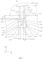
FIG. 3 is a front view of a first electrode plate of the electrode assembly shown inFIG. 2A in some embodiments. -
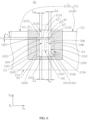
FIG. 4 is a rear view of the first electrode plate shown inFIG. 3 . -
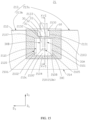
FIG. 5 is a front view of the first electrode plate shown inFIG. 3 after removing a first layer. -
FIG. 6 is a front view of the first electrode plate shown inFIG. 3 in some other embodiments. -
FIG. 7A is a front view of the first electrode plate shown inFIG. 3 in some other embodiments. -
FIG. 7B is a front view of the first electrode plate shown inFIG. 3 in some other embodiments. -
FIG. 8 is a front view of the first electrode plate shown inFIG. 3 in some other embodiments. -
FIG. 9 is a front view of the first electrode plate shown inFIG. 3 in some other embodiments. -
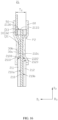
FIG. 10A is a cross-sectional view of the first electrode plate shown inFIG. 3 along X-X in some embodiments. -
FIG. 10B is a cross-sectional view of the first electrode plate shown inFIG. 3 along X-X in some other embodiments. -
FIG. 11 is a cross-sectional view of the first electrode plate shown inFIG. 3 along XI-XI. -
FIG. 12 is a cross-sectional view of the first electrode plate shown inFIG. 3 along XII-XII. -
FIG. 13 is a front view of the first electrode plate shown inFIG. 3 in some other embodiments. -
FIG. 14 is a front view of the first electrode plate shown inFIG. 3 in some other embodiments. -
FIG. 15 is a rear view of a first electrode plate in an electrochemical device according to another embodiment of this application. -
FIG. 16 is a cross-sectional view of the first electrode plate shown inFIG. 15 along XVI-XVI. -
FIG. 17 is a schematic diagram of an overall structure of an electronic device according to an embodiment of this application. -
Electronic device 1 Housing 10 Electrode assembly 20 First electrode plate 21 Second electrode plate 22 Separator 23 First conductive plate 30 Protrusion 30a, 30b, 210d Depression 30c, 210c First side 30A Second side 30B Third side 30C Fourth side 30D First connecting region 31 Second connecting region 32 Third connecting region 33 Second conductive plate 40 First layer 50 First edge 51 Second edge 52 Third edge 53 Fourth edge 54 Second layer 60 Electrochemical device 100 First wall 111 Second wall 112 First current collector 210 First surface 210a Second surface 210b First conductive material layer 211 Second conductive material layer 212 First end edge 213 First connecting edge 213a Second connecting edge 213b Second end edge 214 Second current collector 220 Third surface 220a Fourth surface 220b Third conductive material 221 layer Fourth conductive material 222 layer First region 2100 Second region 2100' First edge 2101 Second edge 2102 Fifth edge 2103 Sixth edge 2104 Third edge 2105 Fourth edge 2106 Seventh edge 2107 Eighth edge 2108 First opening 2110 Second opening 2120 First recess 2130 First recess edge 2131 Second recess edge 2132 Third recess edge 2133 Fourth recess edge 2134 Fifth recess edge 2135 Winding center axis C Winding direction D First direction D1 Second direction D2 Third direction D3 First position P1 Second position P2 Thickness T1, T2 First distance L1 Second distance L2 Third distance L3 Fourth distance L4 Fifth distance L5 Sixth distance L6 - This application will be further described with reference to the accompanying drawings in the following specific embodiments.
- The following describes the technical solutions in some embodiments of this application clearly and in detail. Apparently, the described embodiments are only some rather than all embodiments of this application. Unless otherwise defined, all technical and scientific terms used herein shall have the same meanings as commonly understood by persons skilled in the art to which this application pertains. The terms used in the specification of this application are for description of specific embodiments only without any intention to limit this application.
- The following describes some embodiments of this application in detail. However, this application may be embodied in many different implementations and should not be construed as being limited to some illustrative embodiments described herein. Rather, these illustrative embodiments are provided so that this application can be conveyed to persons skilled in the art thoroughly and in detail.
- In addition, in the accompanying drawings, sizes or thicknesses of various components and layers may be exaggerated for brevity and clarity. Throughout the text, the same numerical values represent the same elements. As used herein, the term "and/or" includes any and all combinations of one or more of the associated listed items. In addition, it should be understood that when an element A is referred to as being "connected to" an element B, the element A can be directly connected the element B or an intermediate element C may be present therebetween such that the element A and the element B are indirectly connected to each other.
- Further, "may" used when describing some embodiments of this application relates to "one or more embodiments of this application".
- The technical terms used herein are merely intended to describe specific embodiments without any intention to limit this application. As used herein, the singular forms are intended to include the plural forms as well, unless otherwise clearly specified in the context. It should be further understood that the term "include" used in this specification indicates the presence of stated features, numerical values, steps, operations, elements, and/or components but does not preclude the presence or addition of one or more other features, numerical values, steps, operations, elements, components, and/or combinations thereof.
- Spatial related terms such as "above" may be used herein for ease of description to describe the relationship between one element or feature and another element (a plurality of elements) or feature (a plurality of features) as illustrated in the figures. It should be understood that spatial related terms are intended to include different orientations of equipment or devices in use or operation in addition to the orientations depicted in the figures. For example, if the equipment in the figures is turned over, elements described as being "above" or "over" other elements or features would then be oriented "below" or "beneath" the other elements or features. Thus, the example term "above" may include both the orientations above and below. It should be understood that although the terms such as first, second, and third may be used herein to describe various elements, components, regions, layers, and/or parts, these elements, components, regions, layers, and/or parts should not be limited by these terms. These terms are used to distinguish one element, component, region, layer, or part from another element, component, region, layer, or part. Therefore, the first element, component, region, layer, or part discussed below may be referred to as the second element, component, region, layer, or part without departing from the teachings of the illustrative embodiments.
- In this application, design relationships between parameter values that are greater than, less than, or not equal to each other need to exclude the reasonable errors of measurement equipment.
- Referring to
FIGs. 1 and2A , an embodiment of this application provides anelectrochemical device 100 including ahousing 10, anelectrode assembly 20, a firstconductive plate 30, and a secondconductive plate 40. Theelectrode assembly 20 is located in thehousing 10. The firstconductive plate 30 and the secondconductive plate 40 are both electrically connected to theelectrode assembly 20 and extend out of thehousing 10 from the inside of thehousing 10. Thehousing 10 may be a packaging bag obtained after packaging by using a packaging film (such as an aluminum-plastic film), that is, theelectrochemical device 100 may be a soft pack battery. In some other embodiments, theelectrochemical device 100 is not limited to a soft pack battery and may alternatively be a steel shell battery or an aluminum shell battery.FIG. 2A shows oneelectrode assemblies 20. In another embodiment, a plurality ofelectrode assemblies 20 may alternatively be provided, and the plurality ofelectrode assemblies 20 are located in thehousing 10 and electrically connected in parallel or in series. - As shown in
FIG. 2A , theelectrode assembly 20 may be a wound structure. Theelectrode assembly 20 includes afirst electrode plate 21, asecond electrode plate 22, and aseparator 23, where theseparator 23 is disposed between thefirst electrode plate 21 and thesecond electrode plate 22. Thefirst electrode plate 21, theseparator 23, and thesecond electrode plate 22 are stacked and then wound sequentially to form theelectrode assembly 20. As shown inFIG. 2A , theelectrode assembly 20 has a winding center axis C perpendicular to the plane of the paper. A winding direction D is a direction rotating counterclockwise around the winding center axis C as shown inFIG. 2A . In some other embodiments, the winding direction D may alternatively be a direction rotating clockwise. In this application, a three-dimensional coordinate system is established based on a first direction D1, a second direction D2, and a third direction D3 perpendicular to each other. The first direction D1 is a direction perpendicular to a surface of the firstconductive plate 30. The second direction D2 is a direction along which the firstconductive plate 30 protrudes from theelectrode assembly 20. In some embodiments, the second direction D2 may alternatively be a direction of the winding center axis C. The third direction D3 is a direction from the firstconductive plate 30 to the secondconductive plate 40. In some other embodiments, theelectrode assembly 20 may alternatively be a laminated structure. - As shown in
FIGs. 2A and2B , thefirst electrode plate 21 includes a firstcurrent collector 210, a firstconductive material layer 211, and a secondconductive material layer 212. The firstcurrent collector 210 includes afirst surface 210a and asecond surface 210b disposed opposite to each other. The firstconductive material layer 211 is disposed on thefirst surface 210a. The secondconductive material layer 212 is disposed on thesecond surface 210b. As shown inFIG. 2A , thesecond electrode plate 22 includes a secondcurrent collector 220, a thirdconductive material layer 221, and a fourthconductive material layer 222. The secondcurrent collector 220 includes athird surface 220a and afourth surface 220b disposed opposite to each other. The thirdconductive material layer 221 is disposed on thethird surface 220a. The fourthconductive material layer 222 is disposed on thefourth surface 220b. The secondconductive material layer 212 and the fourthconductive material layer 222 face each other across theseparator 23. In some embodiments, as shown inFIG. 2A , after stacked and then wound, thefirst surface 210a of the firstcurrent collector 210 is farther from the winding center axis C than thesecond surface 210b, and thethird surface 220a of the secondcurrent collector 220 is farther from the winding center axis C than thefourth surface 220b. It can be understood that in another embodiment, thefirst surface 210a of the firstcurrent collector 210 may alternatively be closer to the winding center axis C, and thethird surface 220a of the secondcurrent collector 220 may alternatively be closer to the winding center axis C than thefourth surface 220b. In some embodiments, in the first direction D1, a thickness range of the firstcurrent collector 210 may be 3 µm to 20 µm, a thickness range of thefirst material layer 211 may be 30 µm to 300 µm, and a thickness range of the secondconductive material layer 212 may be 30 µm to 300 µm. - The
first electrode plate 21 may be a positive electrode plate or a negative electrode plate. Correspondingly, the firstcurrent collector 210 may be a positive electrode current collector or a negative electrode current collector. The firstconductive material layer 211 and the secondconductive material layer 212 may both be positive electrode active material layers or negative electrode active material layers. Thesecond electrode plate 22 may be a negative electrode plate or a positive electrode plate. Correspondingly, the secondcurrent collector 220 may be a negative electrode current collector or a positive electrode current collector. The thirdconductive material layer 221 and the fourthconductive material layer 222 may both be negative electrode active material layers or positive electrode active material layers. In some embodiments, thefirst electrode plate 21 is a positive electrode plate, and thesecond electrode plate 22 is a negative electrode plate. The positive electrode current collector may be an aluminum foil or a nickel foil, and the negative electrode current collector may be at least one of a copper foil, a nickel foil, or a carbon-based current collector. - The positive electrode active material layer contains a positive electrode active material, and the positive electrode active material includes a compound that can reversibly intercalate and deintercalate lithium ions (that is, a lithium intercalation compound). In some embodiments, the positive electrode active material may include a lithium transition metal composite oxide. The lithium transition metal composite oxide contains lithium and at least one element selected from cobalt, manganese, and nickel. In some embodiments, the positive electrode active material is selected from at least one of lithium cobaltate (LiCoO2), a lithium nickel manganese cobalt ternary material (NCM), lithium manganate (LiMn2O4), lithium nickel manganate (LiNi0.5Mn1.5O4), or lithium iron phosphate (LiFePO4).
- The negative electrode active material layer contains a negative electrode active material, and the negative electrode active material is a negative electrode active material known in the art that can reversibly intercalate and deintercalate active ions. This is not limited in this application. For example, the negative electrode active material includes but is not limited to a combination of one or more of graphite, soft carbon, hard carbon, carbon fiber, mesocarbon microbeads, a silicon-based material, a tin-based material, lithium titanate, or another metal capable of forming an alloy with lithium. The graphite may be a combination of one or more selected from a group consisting of artificial graphite, natural graphite, and modified graphite. The silicon-based material may be a combination of one or more selected from a group consisting of elemental silicon, a silicon-oxygen compound, a silicon-carbon composite, and a silicon alloy. The tin-based material may be a combination of one or more selected from a group consisting of elemental tin, a tin-oxygen compound, and a tin alloy.
- The
separator 23 includes at least one of polyethylene, polypropylene, polyvinylidene fluoride, polyethylene glycol terephthalate, polyimide, or aramid. For example, polyethylene includes at least one selected from high-density polyethylene, low-density polyethylene, or ultra-high molecular weight polyethylene. Polyethylene and polypropylene have a good effect on alleviating short circuits and can improve the stability of the electrochemical device through the turn-off effect. - Referring to
FIGs. 3 and5 , the firstconductive material layer 211 includes afirst opening 2110. Thefirst surface 210a of the firstcurrent collector 210 includes afirst region 2100. Thefirst region 2100 is configured to be a region of thefirst surface 210a exposed at thefirst opening 2110. That is, thefirst region 2100 is exposed at thefirst opening 2110. In this case, the first direction D1 may alternatively be a direction perpendicular to thefirst region 2100. In this application, thefirst opening 2110 is cleaned in the firstconductive material layer 211 through a laser cleaning manner, so that thefirst region 2100 is exposed. Alternatively, a foam adhesive may be applied to thefirst region 2100 in advance, and after an active material is applied, heating is performed to make the foam adhesive fall off, thereby making thefirst region 2100 exposed. Alternatively, the active material on thefirst region 2100 can be directly scraped off with a scraper, thereby making thefirst region 2100 exposed. However, it can be understood that after laser cleaning or scraping with the scraper, a small amount of active material may still remain on the surface of thefirst region 2100. This is not limited in this application. - In some embodiments, when viewed from the first direction D1, the
first region 2100 and thefirst opening 2110 may both be rectangular. Specifically, thefirst region 2100 includes afirst edge 2101 and asecond edge 2102 disposed opposite to each other in the third direction D3, and afifth edge 2103 and asixth edge 2104 disposed opposite to each other in the second direction D2. Thefifth edge 2103 is connected between thefirst edge 2101 and thesecond edge 2102, and thesixth edge 2104 is connected between thefirst edge 2101 and thesecond edge 2102. In some embodiments, thefirst edge 2101 and thesecond edge 2102 can both extend along the second direction D2, thefifth edge 2103 and thesixth edge 2104 can both extend along the third direction D3, and thefirst edge 2101, thesecond edge 2102, thefifth edge 2103, and thesixth edge 2104 may all be linear. In some other embodiments, when thefirst region 2100 is formed through manners such as laser cleaning, at least one of thefirst edge 2101, thesecond edge 2102, thefifth edge 2103, and thesixth edge 2104 may alternatively include a corrugated shape. This is not limited in this application. It can be understood that thefirst opening 2110 is a three-dimensional structure, but when viewed from the first direction D1, thefirst opening 2110 includes a plurality of edges connected sequentially (not shown in the figure). When viewed from the first direction D1, thefirst edge 2101, thesecond edge 2102, thefifth edge 2103, and thesixth edge 2104 of thefirst region 2100 respectively overlap with a plurality of edges of thefirst opening 2110. - When viewed from the first direction D1, the first
conductive plate 30 is connected to thefirst region 2100. A first side 30A of the first conductive plate 30 is defined as a position on a side of the first conductive plate 30 in the third direction D3 when viewed from the first direction D1. A second side 30B of the first conductive plate 30 is opposite to the first side 30A and is a position on another side of the first conductive plate 30 in the third direction D3 when viewed from the first direction D1. A third side 30C of the first conductive plate 30 is a position on a side of the first conductive plate 30 in the second direction D2 when viewed from the first direction D1. A fourth side 30D (shown inFIG. 1 ) of the first conductive plate 30 is opposite to the third side 30C and is a position on another side of the first conductive plate 30 in the second direction D2 when viewed from the first direction D1. For example, as shown inFIGs. 3 and5 , the first side 30A of the first conductive plate 30 may refer to a left side of the first conductive plate 30, the second side 30B of the first conductive plate 30 may refer to a right side of the first conductive plate 30, the third side 30C of the first conductive plate 30 may refer to a lower side of the first conductive plate 30, and the fourth side 30D of the first conductive plate 30 may refer to an upper side of the first conductive plate 30. Thethird side 30C of the firstconductive plate 30 is located in thehousing 10, and thefourth side 30D is located outside thehousing 10. When viewed from the first direction D1, in the third direction D3, thefirst edge 2101 is located on thefirst side 30A of the firstconductive plate 30, and thesecond edge 2102 is located on thesecond side 30B of the firstconductive plate 30 opposite to thefirst side 30A. When viewed from the first direction D1, the firstconductive plate 30 covers a part of thefifth edge 2103, and the firstconductive plate 30 overlaps with a part of thefifth edge 2103. To meet the demand for high-current charging of theelectrochemical device 100, thefirst region 2100 may be disposed in a region of thefirst electrode plate 21 other than a winding head and a winding tail. - In some embodiments, the first
conductive plate 30 is welded to thefirst region 2100, so that a high connection strength is present between the firstconductive plate 30 and thefirst region 2100. Referring toFIG. 10A , in some embodiments, at least oneprotrusion 30a may be formed at a welding position between the firstconductive plate 30 and thefirst region 2100. For example, a plurality ofprotrusions 30a arranged in a matrix may be formed at the welding position between the firstconductive plate 30 and thefirst region 2100, and theprotrusions 30a protrude from thefirst region 2100 to the firstconductive plate 30. In addition, at least oneprotrusion 30b is correspondingly formed on a surface of the firstconductive plate 30 facing away from thefirst region 2100. At least onedepression 210c is correspondingly formed on thesecond surface 210b of the firstcurrent collector 210. Theprotrusions depression 210c may be formed during the welding process (which may be referred to as weld marks in this case). However, this is not limited in this application. Referring toFIG. 10B , in some other embodiments, at least onedepression 30c may also be formed at the welding position between the firstconductive plate 30 and thefirst region 2100. For example, a plurality ofdepressions 30c arranged in a matrix may be formed at the welding position between the firstconductive plate 30 and thefirst region 2100. Thedepression 30c is recessed from thefirst region 2100 to the firstconductive plate 30. In addition, at least onedepression 30d is correspondingly formed on the surface of the firstconductive plate 30 facing away from thefirst region 2100, and at least oneprotrusion 210d is correspondingly formed on thesecond surface 210b of the firstcurrent collector 210. Thedepressions protrusion 210d may be formed during the welding process (which may be referred to as weld marks in this case). However, this is not limited in this application. In another embodiment, the firstconductive plate 30 may alternatively be connected to thefirst region 2100 through a conductive adhesive or another manner. In the first direction D1, a thickness range of the firstconductive plate 30 may be 10 µm to 150 µm, and a thickness range of the secondconductive plate 40 may be 10 µm to 150 µm. - As shown in
FIGs. 3 and5 , when viewed from the first direction D1, thefirst electrode plate 21 includes afirst end edge 213 and asecond end edge 214 disposed opposite to each other in the second direction D2. Thesecond end edge 214, thesixth edge 2104, thefifth edge 2103, and thefirst end edge 213 are arranged sequentially in the second direction D2. Thesecond end edge 214, thesixth edge 2104, thefifth edge 2103, and thefirst end edge 213 being arranged sequentially in the second direction D2 means that a virtual straight line set along the second direction D2 successively passes through thesecond end edge 214, thesixth edge 2104, thefifth edge 2103, and thefirst end edge 213. Thefirst end edge 213 and thesecond end edge 214 can both extend along the third direction D3. Thefirst electrode plate 21 is provided with afirst recess 2130 at thefirst end edge 213. Thefirst recess 2130 can be formed through a laser cutting manner or a die cutting manner. When viewed from the first direction D1, thefirst opening 2110 is spaced apart from thefirst recess 2130, so that a part of the firstconductive material layer 211 is present between thefirst opening 2110 and thefirst recess 2130. When viewed from the first direction D1, thefirst opening 2110 may be spaced apart from thesecond end edge 214. When viewed from the second direction D2, thefirst region 2100 overlaps with thefirst recess 2130. Here, overlapping means that the two are at least partially covered in a direction. For example, as shown inFIGs. 3 to 5 , when viewed from the second direction D2, thefirst recess 2130 covers a part of thefirst region 2100. For another example, as shown inFIG. 6 , in some other embodiments, when viewed from the second direction D2, thefirst recess 2130 fully covers thefirst region 2100, and thefirst region 2100 also fully covers thefirst recess 2130 in the second direction D2 (that is, the two overlap each other). When viewed from the first direction D1, the firstconductive plate 30 covers a part of thefirst region 2100, and the firstconductive plate 30 also covers a part of the first conductive material layer 211 (that is, the firstconductive plate 30 covers this part of the firstconductive material layer 211 located between thefirst opening 2110 and the first recess 2130), and the firstconductive plate 30 also covers a part of thefirst recess 2130. Specifically, the firstconductive plate 30 includes a first connectingregion 31, a second connectingregion 32, and a third connectingregion 33 connected sequentially in the second direction D2. When viewed from the first direction D1, the first connectingregion 31 covers a part of thefirst region 2100, and a weld mark may be formed on the first connectingregion 31; the second connectingregion 32 covers a part of the firstconductive material layer 211; and the third connectingregion 33 covers a part of thefirst recess 2130. The third connectingregion 33 extends beyond thefirst end edge 213 in the second direction D2 and further extends out of thehousing 10. The first connectingregion 31 is a position where the current flows through when theelectrochemical device 100 is charged, and heat generated in the first connectingregion 31 when theelectrochemical device 100 is charged can be dissipated through thefirst region 2100 exposed at the first connectingregion 31. Referring toFIGs. 11 and12 , it can be understood that this part of the firstconductive material layer 211 present between thefirst opening 2110 and thefirst recess 2130 can increase the height in the first direction D1, and the presence of this part of the firstconductive material layer 211 reduces the height difference in the first direction D1 with a weld mark (such as theprotrusion 30b), and even this part of the firstconductive material layer 211 may be higher than the weld mark in the first direction D1. Therefore, in the event of mechanical abuse, if a position to which the external force is applied overlaps with a weld mark of the firstconductive plate 30, especially when the external force is applied to the front of the electrochemical device 100 (for example, thehousing 10 faces afirst wall 111 of thefirst region 2100 as shown inFIG. 2A ), this part of the firstconductive material layer 211 capable of increasing the height can bear part of the external force, reducing the possibility of the weld mark piercing theseparator 23 and causing a short circuit due to contact with thesecond electrode plate 22, thereby prolonging the service life of theelectrochemical device 100. - As shown in
FIGs. 3 and5 , in some embodiments, thefirst recess 2130 includes afirst recess edge 2131, asecond recess edge 2132, and athird recess edge 2133. Thefirst recess edge 2131 and thesecond recess edge 2132 are disposed opposite to each other in the third direction D3. Thefirst recess edge 2131 and thesecond recess edge 2132 can both extend along the second direction D2, and thethird recess edge 2133 can extend along the third direction D3. When thefirst recess edge 2131 extends along the second direction D2, thefirst recess edge 2131 may be parallel to the second direction D2 or may be inclined relative to the second direction D2 (that is, an included angle between thefirst recess edge 2131 and the second direction D2 is less than 90°), but the overallfirst recess edge 2131 is not parallel to the third direction D3. Thesecond recess edge 2132 extends along the second direction D2 in the same way. Thethird recess edge 2133 connects thefirst recess edge 2131 and thesecond recess edge 2132. Thefirst recess edge 2131, thesecond recess edge 2132, and thethird recess edge 2133 enclose thefirst recess 2130. When viewed from the first direction D1, thefirst opening 2110 is spaced apart from thethird recess edge 2133 of thefirst recess 2130. When viewed from the first direction D1, thefirst edge 2101 and thefirst recess edge 2131 are both located on thefirst side 30A of the firstconductive plate 30, thesecond edge 2102 and thesecond recess edge 2132 are both located on thesecond side 30B of the firstconductive plate 30, and the firstconductive plate 30 covers a part of thethird recess edge 2133. In some specific embodiments, when viewed from the first direction D1, thefirst recess 2130 may be approximately rectangular, and thefirst recess edge 2131, thesecond recess edge 2132, and thethird recess edge 2133 are all linear. When viewed from the first direction D1, a virtual boundary line between the first connectingregion 31 and the second connectingregion 32 overlaps with thefifth edge 2103, and a virtual boundary line between the second connectingregion 32 and the third connectingregion 33 overlaps with thethird recess edge 2133. - Further, when viewed from the first direction D1, the
first end edge 213 includes a first connectingedge 213a connecting to thefirst recess edge 2131 and a second connectingedge 213b connecting to thesecond recess edge 2132. The first connectingedge 213a and the second connectingedge 213b can both extend along the third direction D3. When viewed from the first direction D1, the first connectingedge 213a is located on thefirst side 30A of the firstconductive plate 30, and the second connectingedge 213b is located on thesecond side 30B of the firstconductive plate 30. - As shown in
FIG. 7A , in some other embodiments, a shape of thefirst recess 2130 may alternatively be changed. For example, when viewed from the first direction D1, thefirst recess 2130 may alternatively be approximately U-shaped. In this case, thefirst recess 2130 includes afirst recess edge 2131, asecond recess edge 2132, athird recess edge 2133, afourth recess edge 2134, and afifth recess edge 2135. Thefirst recess edge 2131 and thesecond recess edge 2132 are disposed opposite to each other in the third direction D3. Thefirst recess edge 2131 and thesecond recess edge 2132 can both extend along the second direction D2, and thethird recess edge 2133 can extend along the third direction D3. Thefourth recess edge 2134 connects thefirst recess edge 2131 and thethird recess edge 2133, and thefourth recess edge 2134 is curved. Thefifth recess edge 2135 connects thesecond recess edge 2132 and thethird recess edge 2133, and thefifth recess edge 2135 is curved. Thefirst recess edge 2131, thesecond recess edge 2132, thethird recess edge 2133, thefourth recess edge 2134, and thefifth recess edge 2135 enclose thefirst recess 2130. In some specific embodiments, thefirst recess edge 2131, thesecond recess edge 2132, and thethird recess edge 2133 are all linear, and thefourth recess edge 2134 and thefifth recess edge 2135 are both arc-shaped and protrude away from thefirst recess 2130. In some other embodiments, thethird recess edge 2133 may alternatively be arc-shaped. With the provision of the curvedfourth recess edge 2134 andfifth recess edge 2135, a smooth transition is present between thefirst recess edge 2131 and thethird recess edge 2133 and between thesecond recess edge 2132 and thethird recess edge 2133. This is conducive to reducing the burrs generated at the transition positions during cutting thefirst recess 2130, thereby reducing the possibility of the burrs piercing theseparator 23 and causing a short circuit due to contact with thesecond electrode plate 22, and prolonging the service life of theelectrochemical device 100. In addition, the provision of the curvedfourth recess edge 2134 andfifth recess edge 2135 can increase an area of the firstconductive material layer 211 located between thefirst opening 2110 and thefirst recess 2130 and capable of increasing the height. This allows this part of the firstconductive material layer 211 to bear the external force in the event of mechanical abuse. - As shown in
FIG. 7B , in some other embodiments, thefirst recess edge 2131 can be curved, and thesecond recess edge 2132 can also be curved. In some specific embodiments, thefirst recess edge 2131 is arc-shaped and protrudes away from thefirst recess 2130. Thesecond recess edge 2132 is also arc-shaped and protrudes away from thefirst recess 2130. In this case, a smooth transition may also be present between thefirst recess edge 2131 and thethird recess edge 2133 and between thesecond recess edge 2132 and thethird recess edge 2133. This is conducive to reducing the burrs generated at the transition positions during cutting thefirst recess 2130, thereby reducing the possibility of the burrs piercing theseparator 23 and causing a short circuit due to contact with thesecond electrode plate 22, and prolonging the service life of theelectrochemical device 100. - As shown in
FIG. 8 , in some other embodiments, when viewed from the first direction D1, thefirst recess 2130 may alternatively be approximately V-shaped. In this case, thefirst recess 2130 includes only thefirst recess edge 2131 and thesecond recess edge 2132. Thefirst recess edge 2131 and thesecond recess edge 2132 can both extend away from the second direction D2. Thefirst recess edge 2131 is directly connected to thesecond recess edge 2132, and thefirst recess edge 2131 and thesecond recess edge 2132 enclose thefirst recess 2130. In some specific embodiments, thefirst recess edge 2131 and thesecond recess edge 2132 are both linear. - Referring to
FIG. 4 , in some embodiments, thesecond surface 210b of the firstcurrent collector 210 includes a second region 2100'. The secondconductive material layer 212 includes asecond opening 2120. The second region 2100' is configured to be a region of thesecond surface 210b exposed at thesecond opening 2120. That is, the second region 2100' is exposed at thesecond opening 2120. When viewed from the first direction D1, thefirst region 2100 and the second region 2100' overlap. Thus, when theelectrochemical device 100 is charged, heat generated at the firstconductive plate 30 can be dissipated through thefirst region 2100 exposed at the first connectingregion 31 and can also be transferred to the second region 2100' through a position where thefirst region 2100 and the second region 2100' overlap and then dissipated through the second region 2100', reducing the possibility of local overheating of the firstconductive plate 30. When viewed from the second direction D2, the second region 2100' overlaps with thefirst recess 2130. - In some embodiments, the second region 2100' may connect to the
first recess 2130. Therefore, when viewed from the first direction D1, there is no secondconductive material layer 212 between the second region 2100' and thefirst recess 2130. Therefore, thefirst electrode plate 21 located between thefirst opening 2110 and thefirst recess 2130 is a single-sided coating region. - In some embodiments, when viewed from the first direction D1, the second region 2100' and the
second opening 2120 may both be rectangular. The second region 2100' includes athird edge 2105 and afourth edge 2106 disposed opposite to each other in the third direction D3, and aseventh edge 2107 and aneighth edge 2108 disposed opposite to each other in the second direction D2. Theseventh edge 2107 is connected between thethird edge 2105 and thefourth edge 2106, and theeighth edge 2108 is connected between thethird edge 2105 and thefourth edge 2106. Thethird edge 2105 and thefourth edge 2106 can both extend along the second direction D2, and theseventh edge 2107 and theeighth edge 2108 can both extend along the third direction D3. As shown inFIGs. 3 to 5 , when viewed from the first direction D1, thefirst edge 2101 and thethird edge 2105 are located on thefirst side 30A of the firstconductive plate 30, and thesecond edge 2102 and thefourth edge 2106 are located on thesecond side 30B of the firstconductive plate 30. When viewed from the first direction D1, the firstconductive plate 30 covers theseventh edge 2107. When viewed from the first direction D1, thesixth edge 2104 may overlap with theeighth edge 2108. In some other embodiments, as shown inFIG. 9 , thesixth edge 2104 and theeighth edge 2108 may alternatively be staggered with each other in the second direction D2. In some embodiments, as shown inFIGs. 3 to 5 , thesixth edge 2104 overlaps with theeighth edge 2108. The second region 2100' connects to thefirst recess 2130, so that thefifth edge 2103 and theseventh edge 2107 are staggered with each other in the second direction D2, and theseventh edge 2107 is closer to thefirst end edge 213 than thefifth edge 2103. When viewed from the first direction D1, theseventh edge 2107 overlaps with thethird recess edge 2133. Therefore, in the second direction D2, thesecond end edge 214, theeighth edge 2108, thefifth edge 2103, the seventh edge 2107 (the third recess edge 2133), and thefirst end edge 213 are arranged sequentially. Since there is no secondconductive material layer 212 between the second region 2100' and thefirst recess 2130, the amount of the conductive material used is reduced. In addition, this reduces the possibility of the conductive material falling off and causing a short circuit when the weld mark (such as thedepression 210c shown inFIG. 10A or theprotrusion 210d shown inFIG. 10B ) extends beyond thefifth edge 2103 and falls onto this part of the secondconductive material layer 212, thereby prolonging the service life of theelectrochemical device 100. It can be understood that thesecond opening 2120 is a three-dimensional structure, but when viewed from the first direction D1, thesecond opening 2120 includes a plurality of edges connected sequentially (not shown in the figure). When viewed from the first direction D1, thethird edge 2105, thefourth edge 2106, theseventh edge 2107, and theeighth edge 2108 of the second region 2100' respectively overlap with a plurality of edges of thesecond opening 2120. - It can be understood that if the
first recess 2130 is not provided, after the firstconductive plate 30 is connected to thefirst region 2100, a position with a larger thickness in thefirst electrode plate 21 having the firstconductive plate 30 should be, when viewed from the first direction D1, a region where the firstconductive material layer 211, the firstcurrent collector 210, and the secondconductive material layer 212 overlap with the first conductive plate 30 (including a total thickness of the firstconductive plate 30, the firstconductive material layer 211, the firstcurrent collector 210, and the second conductive material layer 212). - As shown in
FIGs. 10A to 12 , in this application, after thefirst recess 2130 is provided, the position with a larger thickness in thefirst electrode plate 21 having the firstconductive plate 30 should be, when viewed from the first direction D1, a position of thefirst electrode plate 21 with a double-sided coating on both sides of thefirst region 2100 in the third direction D3 (hereinafter referred to as a first position P1, where a thickness T1 of the first position P1 includes a total thickness of the firstconductive material layer 211, the firstcurrent collector 210, and the second conductive material layer 212), or a region overlapping with the firstconductive plate 30 between thefirst opening 2110 and the first recess 2130 (hereinafter referred to as a second position P2, where a thickness T2 of the second position P2 includes a total thickness of the firstconductive plate 30, the firstconductive material layer 211, and the first current collector 210). - Therefore, in this application, the provision of the
first recess 2130 is conducive to reducing the overall thickness of theelectrochemical device 100 in the first direction D1 and improving space utilization. In addition, in the event of mechanical abuse, if the position to which the external force is applied overlaps with the weld mark of the firstconductive plate 30, especially when the external force is applied to the front of theelectrochemical device 100, the first position P1 or the second position P2 with a larger thickness in thefirst electrode plate 21 can bear part of the external force, reducing the possibility of the weld mark (such as theprotrusion 30b) piercing theseparator 23 and causing a short circuit due to contact with thesecond electrode plate 22, thereby prolonging the service life of theelectrochemical device 100. In addition, thefirst electrode plate 21 may wrinkle under the action of the external force, allowing thefirst end edge 213 orsecond end edge 214 of thefirst electrode plate 21 to bend toward the middle of thefirst electrode plate 21. In this case, thefirst recess 2130 can provide a buffer space for the third connectingregion 33 of the firstconductive plate 30, reducing the possibility of the firstconductive plate 30 bending with thefirst electrode plate 21 and undergoing breakage, thereby further prolonging the service life of theelectrochemical device 100. Especially, as shown inFIGs. 3 ,7A , and7B , when thefirst recess 2130 includes thefirst recess edge 2131, thesecond recess edge 2132, and thethird recess edge 2133, thefirst recess 2130 with the above structure can provide a large buffer space for the firstconductive plate 30 in the event of mechanical abuse. - In some embodiments, the
second electrode plate 22 can alternatively adopt a design similar to that of thefirst electrode plate 21. For example, a third region (for example, a blank region) is provided on the secondcurrent collector 220 of thesecond electrode plate 22 to be connected to the secondconductive plate 40. Thesecond electrode plate 22 is provided with a second recess at an end edge, and the thirdconductive material layer 221 corresponds to the third region being the blank region and is spaced apart from thefirst recess 2130 in the second direction D2. Thus, this can further improve the space utilization and prolong the service life of theelectrochemical device 100. - As shown in
FIGs. 10A to 12 , in some embodiments, in the first direction D1, a thickness of the firstconductive plate 30 is less than a thickness of the firstconductive material layer 211. Therefore, after the firstconductive plate 30 is connected to thefirst region 2100, the position with a larger thickness in thefirst electrode plate 21 having the firstconductive plate 30 is the position of thefirst electrode plate 21 with a double-sided coating on both sides of thefirst region 2100 in the third direction D3, that is, the first position P1. Therefore, in the event of mechanical abuse, if the position to which the external force is applied overlaps with the weld mark of the firstconductive plate 30, the first position P1 can preferentially bear part of the external force. In addition, when viewed from the first direction D1, the first position P1 has a larger area than the second position P2, which is conducive to bearing greater external force in the event of mechanical abuse, thereby further prolonging the service life of theelectrochemical device 100. - As shown in
FIGs. 3 and10A to 12 , in some embodiments, theelectrochemical device 100 further includes afirst layer 50 containing an insulating material. Thefirst layer 50 is adhered to thefirst region 2100. The firstconductive plate 30 is disposed between thefirst region 2100 and thefirst layer 50. Thefirst layer 50 is used to cover the weld mark (such as theprotrusion 30b) of the firstconductive plate 30, thereby reducing the risk of the weld mark piercing theseparator 23 and causing a short circuit. Thefirst layer 50 may be a single-sided adhesive tape or a double-sided adhesive tape, and a specific material of thefirst layer 50 may be selected from at least one of polypropylene, polyethylene, poly(vinylidene difluoride), vinylidene difluoride-hexafluoropropylene copolymer, polymethyl methacrylate, or polyethylene glycol. In another embodiment, thefirst layer 50 may alternatively be a ceramic coating. In the first direction D1, a thickness range of thefirst layer 50 may be 3 µm to 30 µm. - In some embodiments, when viewed from the first direction D1, the
first layer 50 fully covers thefirst opening 2110 and thefirst recess 2130, and also covers the firstconductive material layer 211 located between thefirst opening 2110 and thefirst recess 2130. In addition, thefirst layer 50 extends beyond thefirst end edge 213 in the second direction D2. Specifically, when viewed from the first direction D1, thefirst layer 50 includes afirst edge 51 and asecond edge 52 disposed opposite to each other in the second direction D2, and further includes athird edge 53 and afourth edge 54 disposed opposite to each other in the third direction D3. Thefirst edge 51 and thesecond edge 52 can both extend along the third direction D3. Thethird edge 53 and thefourth edge 54 can both extend along the third direction D3. Thethird edge 53 is connected between thefirst edge 51 and thesecond edge 52, and thefourth edge 54 is connected between thefirst edge 51 and thesecond edge 52. Thefirst edge 51 extends beyond thefirst end edge 213 in the second direction D2. When viewed from the first direction D1, thesecond edge 52 may be located between thesixth edge 2104 and thesecond end edge 214. Thethird edge 53 is located on thefirst side 30A of the firstconductive plate 30, and in the third direction D3, thefirst edge 2101 is located between thethird edge 53 and the firstconductive plate 30. Thefourth edge 54 may be located on thesecond side 30B of the firstconductive plate 30, and in the third direction D3, thesecond edge 2102 is located between thefourth edge 54 and the firstconductive plate 30. Thus, thefirst layer 50 can also cover the burrs generated at thefirst end edge 213 during cutting the firstcurrent collector 210, reducing the possibility of the burrs piercing theseparator 23 and causing a short circuit due to contact with thesecond electrode plate 22. When viewed from the first direction D1, thefirst layer 50 can also cover a part of the firstconductive material layer 211. For ease of distinction, inFIG. 3 , the firstconductive material layer 211 covered by thefirst layer 50 and another firstconductive material layer 211 are shown in different filling manners. However, it can be understood that this does not mean that the firstconductive material layer 211 covered by thefirst layer 50 and the another first conductive material layers 211 are made of different active materials, and there is no clear boundary between the two. It can be understood that as shown inFIG. 7A , when the curvedfourth recess edge 2134 andfifth recess edge 2135 are provided, the area of the firstconductive material layer 211 located between thefirst opening 2110 and thefirst recess 2130 and capable of increasing the height is increased. This is also conducive to increasing a contact area between thefirst layer 50 and the firstconductive material layer 211, and enhancing the connection strength of thefirst layer 50 on thefirst electrode plate 21. - As shown in
FIGs. 5 and10A to 12 , theelectrochemical device 100 further includes asecond layer 60 containing an insulating material. Thesecond layer 60 is adhered to the second region 2100'. Thesecond layer 60 is used to cover the weld mark (such as theprotrusion 210d), thereby reducing the risk of the weld mark piercing theseparator 23 and causing a short circuit. In some embodiments, thesecond layer 60 may be a single-sided adhesive tape, a double-sided adhesive tape, or a ceramic coating. - As shown in
FIGs. 3 and5 , in some embodiments, in the second direction D2, a distance from the first connectingedge 213a to thethird recess edge 2133 is a first distance L1, a distance from thethird recess edge 2133 to thefirst region 2100 is a second distance L2, and L2 is also a size of this part of the firstconductive material layer 211 located between thefirst opening 2110 and thefirst recess 2130 in the second direction D2. The first distance L1 is greater than the second distance L2 (L1 > L2). A large first distance L1 is conducive to increasing an area of thefirst recess 2130 and allows thefirst recess 2130 to provide a large buffer space for the firstconductive plate 30 in the event of mechanical abuse. In addition, it can be understood that a part of the firstconductive material layer 211 located between thefirst opening 2110 and thefirst recess 2130 is covered by thefirst layer 50, and a material in this part of the firstconductive material layer 211 is difficult to implement capacity utilization during charging and discharging. In addition, thefirst region 2100 needs to reserve a sufficient space in the second direction D2 to be connected to the firstconductive plate 30. Therefore, under a condition that a size of thefirst electrode plate 21 in the second direction D2 is specified, when the second distance L2 is small (the amount of an active material that is covered by thefirst layer 50 and is difficult to implement capacity utilization is reduced), a distance from thesixth edge 2104 to thesecond end edge 214 may be increased (that is, the amount of an active material that is located between thesixth edge 2104 and thesecond end edge 214, is not covered by thefirst layer 50, and is capable of implementing capacity utilization is increased), thereby reducing the influence on the capacity of theelectrochemical device 100. In some other embodiments, the first distance L1 may alternatively be less than the second distance L2. In this case, since the second distance L2 is large, the firstconductive material layer 211 located between thefirst opening 2110 and thefirst recess 2130 can effectively increase the height. - It can be understood that as shown in
FIG. 8 , if thefirst recess 2130 is approximately V-shaped when viewed from the first direction D1, the first distance L1 is a distance in the second direction D2 from the first connectingedge 213a to an intersection of thefirst recess edge 2131 and thesecond recess edge 2132. The second distance L2 is a distance in the second direction D2 from the intersection of thefirst recess edge 2131 and thesecond recess edge 2132 to thefirst region 2100. - When the first distance L1 is greater than the second distance L2, in some embodiments, a range of the first distance L1 is 1 mm to 6 mm (1 mm ≤ L1 ≤ 6 mm), and a range of the second distance L2 is 0.3 mm to 4 mm (0.3 mm ≤ L2 ≤ 4 mm), and 0.1 ≤ L2/L1 < 1. Setting the range of the first distance L1 allows the
first recess 2130 to provide a large buffer space for the firstconductive plate 30 in the event of mechanical abuse. In addition, as compared with a situation where the first distance L1 is large (that is, the area of thefirst recess 2130 is increased, and an area of the firstconductive material layer 211 removed within thefirst recess 2130 is also increased), this application can reduce the influence on the capacity of theelectrochemical device 100. Setting the range of the second distance L2 allows the firstconductive material layer 211 located between thefirst opening 2110 and thefirst recess 2130 to effectively increase the height. In addition, as compared with the situation where the second distance L2 is large, this application can reduce the influence on the capacity of theelectrochemical device 100. In some embodiments, a range of a ratio of the second distance L2 to the first distance L1 is 0.1 to 1. That is, 0.1 ≤ L2/L1 < 1. Setting a lower limit value of the ratio of the second distance L2 to the first distance L1 reduces the possibility that the first distance L1 takes up a large proportion (the area of thefirst recess 2130 is large) or the size of this part of the firstconductive material layer 211 located between thefirst opening 2110 and thefirst recess 2130 in the second direction D2 is small. Therefore, this application can reduce the influence on the capacity of theelectrochemical device 100 and also allows this part of the firstconductive material layer 211 to effectively increase the height. - As shown in
FIGs. 3 and5 , in some embodiments, when viewed from the first direction D1, the firstconductive plate 30 covers a middle position of thefirst recess 2130 in the third direction D3. Therefore, in the third direction D3, a distance from the firstconductive plate 30 to thefirst recess edge 2131 is a third distance L3, a distance from the firstconductive plate 30 to thesecond recess edge 2132 is a fourth distance L4, and the third distance L3 is approximately equal to the fourth distance L4. For example, a difference between the third distance L3 and the fourth distance L4 does not exceed ±1.5 mm. In some specific embodiments, a range of the third distance L3 is 1 mm to 8 mm, and a range of the fourth distance L4 is 1 mm to 8 mm. Thus, this allows thefirst recess 2130 to provide a sufficient buffer space for the firstconductive plate 30 and also reduces the influence on the capacity of theelectrochemical device 100 when the third distance L3 or the fourth distance L4 is excessively large. - It can be understood that as shown in
FIG. 7B , if extending directions of thefirst recess edge 2131 and thesecond recess edge 2132 are not strictly parallel to the second direction D2, the third distance L3 is a maximum distance in the second direction D2 from the firstconductive plate 30 to thefirst recess edge 2131, and the fourth distance L4 is a maximum distance in the second direction D2 from the firstconductive plate 30 to thesecond recess edge 2132. As shown inFIG. 8 , if thefirst recess 2130 is approximately V-shaped when viewed from the first direction D1, the third distance L3 is the maximum distance in the second direction D2 from the firstconductive plate 30 to thefirst recess edge 2131. The fourth distance L4 is the maximum distance in the second direction D2 from the firstconductive plate 30 to thesecond recess edge 2132. - As shown in
FIG. 13 , in some other embodiments, when viewed from the first direction D1, the firstconductive plate 30 can alternatively deviate from the middle position of thefirst recess 2130 in the third direction D3, so that the third distance L3 is not equal to the fourth distance L4. In some specific embodiments, the third distance L3 may be less than the fourth distance L4. - As shown in
FIGs. 3 and5 , in some embodiments, when viewed from the first direction D1, the firstconductive plate 30 covers a middle position of thefirst region 2100 in the third direction D3. Therefore, in the third direction D3, a distance from thefirst edge 2101 to the firstconductive plate 30 is a fifth distance L5, a distance from thesecond edge 2102 to the firstconductive plate 30 is a sixth distance L6, and the fifth distance L5 is approximately equal to the sixth distance L6. For example, a difference between the fifth distance L5 and the sixth distance L6 does not exceed ±1.5 mm. The fifth distance L5 and the sixth distance L6 are actually the sizes of thefirst region 2100 exposed at the first connectingregion 31 of the firstconductive plate 30 in the third direction D3. In some specific embodiments, a range of the fifth distance L5 is 1 mm to 10 mm, and a range of the sixth distance L6 is 1 mm to 10 mm. Thus, heat generated in the first connectingregion 31 when theelectrochemical device 100 is charged can be dissipated through thefirst region 2100 exposed at the first connectingregion 31, reducing the possibility of local overheating of the firstconductive plate 30, and reducing the influence on the capacity of theelectrochemical device 100 when the fifth distance L5 or the sixth distance L6 is excessively large. - As shown in
FIG. 13 , in some other embodiments, when viewed from the first direction D1, if the firstconductive plate 30 deviates from the middle position of thefirst region 2100 in the third direction D3, the fifth distance L5 may alternatively be less than or greater than the sixth distance L6. This is conducive to reducing the process requirements when the firstconductive plate 30 is connected to thefirst region 2100. - As shown in
FIGs. 3 and5 , in some embodiments, when thefirst recess 2130 covers only a part of thefirst region 2100 in the second direction D2, the fourth distance L4 is less than the sixth distance L6. As shown inFIG. 6 , in some other embodiments, when thefirst recess 2130 fully overlaps with thefirst region 2100 in the second direction D2, the fourth distance L4 may alternatively be approximately equal to the sixth distance L6. For example, a difference between the fourth distance L4 and the sixth distance L6 does not exceed ±1.5 mm. - The first distance L1 to the sixth distance L6 can be respectively measured using a direct measurement method. The test steps are as follows: the
electrochemical device 100 is disassembled, and thefirst electrode plate 21 is taken as a test sample; and a caliper or another suitable measuring tool is used to directly measure the values of the first distance L1 to the sixth distance L6, or an image of thefirst electrode plate 21 is collected and measurement is performed in the image. - As shown in
FIGs. 3 to 5 , in some embodiments, when viewed from the first direction D1, thefirst region 2100 and the second region 2100' may be staggered in the third direction D3. In some specific embodiments, when viewed from the first direction D1, thefirst edge 2101 and thethird edge 2105 are staggered with each other in the third direction D3, and thesecond edge 2102 and thefourth edge 2106 are staggered with each other in the third direction D3. Thefirst edge 2101 and thethird edge 2105 are staggered with each other, so that thefirst electrode plate 21 has thickness transitions at positions corresponding to thefirst edge 2101 and thethird edge 2105. Similarly, thesecond edge 2102 and thefourth edge 2106 are staggered with each other, so that thefirst electrode plate 21 has thickness transitions at positions corresponding to thesecond edge 2102 and thefourth edge 2106. The above thickness transitions are conducive to reducing the possibility of the firstcurrent collector 210 undergoing damage such as wrinkles due to sudden pressure increase when the electrode plate is rolled, thereby reducing the possibility of poor appearance or poor internal interface of theelectrochemical device 100. Furthermore, in the event of collision or extrusion due to the external force, the above thickness transitions can also reduce the possibility of tearing of the firstcurrent collector 210. Therefore, the service life of theelectrochemical device 100 is prolonged. - Further, in some embodiments, when viewed from the first direction D1, the second region 2100' fully covers the
first region 2100. That is, when viewed from the first direction D1, an area of the second region 2100' is greater than an area of thefirst region 2100, so that a projection of thefirst region 2100 in the first direction D1 is fully located in a projection of the second region 2100'. Thus, when viewed from the first direction D1, the weld mark (such as thedepression 210c shown inFIG. 10A or theprotrusion 210d shown inFIG. 10B ) can fully fall within a range of the second region 2100', reducing the possibility of a conductive material falling off and causing a short circuit when the weld mark falls on the secondconductive material layer 212, thereby prolonging the service life of theelectrochemical device 100. - Referring to
FIG. 14 , in some other embodiments, when viewed from the first direction D1, thefirst region 2100 may alternatively fully overlap with the second region 2100'. Specifically, when viewed from the first direction D1, thefirst edge 2101 overlaps with thethird edge 2105, thesecond edge 2102 overlaps with thefourth edge 2106, thefifth edge 2103 overlaps with theseventh edge 2107, and thesixth edge 2104 overlaps with theeighth edge 2108. In this case, when viewed from the first direction D1, the area of thefirst region 2100 is equal to the area of the second region 2100'. - Referring to
FIGs. 15 and16 , another embodiment of this application further provides an electrochemical device (not shown in the figure). The electrochemical device differs from the foregoingelectrochemical device 100 in that in thefirst electrode plate 21, the second region 2100' is spaced apart from thefirst recess 2130 in the second direction D2, so that a part of the secondconductive material layer 212 is present between thesecond opening 2120 and thefirst recess 2130. Therefore, when viewed from the first direction D1, thefirst electrode plate 21 located between thefirst opening 2110 and thefirst recess 2130 is a double-sided coating region. - As shown in
FIG. 16 , in this case, the thickness T2 of the second position P2 includes the total thickness of the firstconductive plate 30, the firstconductive material layer 211, the firstcurrent collector 210, and the secondconductive material layer 212. In this case, at the second position P2, this part of the secondconductive material layer 212 located between thesecond opening 2120 and thefirst recess 2130 can also increase the height in the first direction D1. When the external force is applied to the back of the electrochemical device 100 (that is, thehousing 10 faces thesecond wall 112 of the second region 2100' as shown inFIG. 2A ), this part of the secondconductive material layer 212 can also bear part of the external force, reducing the possibility of the weld mark (such as thedepression 210c or theprotrusion 210d) piercing theseparator 23 and causing a short circuit due to contact with thesecond electrode plate 22, thereby prolonging the service life of the electrochemical device. - The electrochemical device (such as the electrochemical device 100) of this application includes all devices capable of undergoing electrochemical reactions. Specifically, the electrochemical device includes all types of primary batteries, secondary batteries, fuel batteries, solar batteries, or capacitors (for example, super capacitors). Optionally, the electrochemical device may be a lithium secondary battery, including a lithium metal secondary battery, a lithium-ion secondary battery, a lithium polymer secondary battery, and a lithium-ion polymer secondary battery.
- Referring to
FIG. 17 , an embodiment of this application further provides anelectronic device 1, theelectronic device 1 includes an electrochemical device (such as the electrochemical device 100). Theelectronic device 1 is powered by theelectrochemical device 100, and theelectrochemical device 100 has a long service life. Theelectrochemical device 100 of this application is applicable toelectronic devices 1 in various fields. In an embodiment, theelectronic device 1 of this application may be but is not limited to a notebook computer, a pen-input computer, a mobile computer, an electronic book player, a portable telephone, a portable fax machine, a portable copier, a portable printer, a stereo headset, a video recorder, a liquid crystal television, a portable cleaner, a portable CD player, a mini-disc, a transceiver, an electronic notebook, a calculator, a memory card, a portable recorder, a radio, a standby power source, a motor, an automobile, a motorcycle, a motor bicycle, a bicycle, a lighting appliance, a toy, a game console, a timepiece, an electric tool, a flash lamp, a camera, a large household battery, a lithium-ion capacitor, and the like. - The following will describe this application in detail with reference to specific examples and comparative examples. An example in which the electrochemical device is used as a battery, the first electrode plate is used as a positive electrode, and the first conductive plate is used as a positive electrode conductive plate is used to describe this application with reference to specific test methods.
- Referring to
FIG. 3 , after cold pressing, thefirst opening 2110 was cleaned in the firstconductive material layer 211 on thefirst electrode plate 21 through a laser cleaning manner, so that thefirst region 2100 was exposed at thefirst opening 2110. Thefirst electrode plate 21 was provided with thefirst recess 2130 at thefirst end edge 213. When viewed from the first direction D1, thefirst opening 2110 was spaced apart from thefirst recess 2130. Then, the firstconductive plate 30 was welded to thefirst region 2100. Thesecond electrode plate 22, theseparator 23, and an electrolyte might be conventionally designed. Thefirst electrode plate 21, theseparator 23, and thesecond electrode plate 22 were stacked and then wound. The resulting product was placed in the housing, followed by electrolyte injection and packaging, to obtain a battery, where thefirst electrode plate 21 was a cathode electrode plate. - Examples 1 to 9 differed from each other in the value of the first distance L1, the value of the second distance L2, or the ratio of the second distance L2 to the first distance L1.
- This comparative example differed from Examples 1 to 9 in that the
first electrode plate 21 was not provided with thefirst recess 2130. - 20 batteries of each example and comparative example were respectively subjected to a blunt penetration test (also known as Dent test). The blunt penetration test included the following specific steps: (1) under an environmental condition of 25±5°C, the battery was charged to 100% SOC (State of Charge, state of charge); (2) a triangular bar extruder (model: DKBF-3KH, manufacturer: Dae Kyung) was used, a position, corresponding to the weld mark of the first
conductive plate 30 on the front of the battery was extruded using a semi-circular headed nail with a diameter of 6 mm, and then the pressure increased to 1300 N at a speed of 300 N/min; and (3) whether the battery undergone failure was observed. A Dent pass rate was calculated using the following formula: Dent pass rate = the number of batteries passing the Dent test/the number of tested batteries. The results were recorded in Table 1.Table 1 First recess L1 (mm) L2 (mm) L2/L1 Dent pass rate Example 1 Presence 6 0.3 0.05 14/20 Example 2 Presence 5 0.5 0.1 20/20 Example 3 Presence 4 1.2 0.3 20/20 Example 4 Presence 1 0.5 0.5 20/20 Example 5 Presence 4 3 0.75 20/20 Example 6 Presence 4 4 1 20/20 Example 7 Presence 3 3 1 20/20 Example 8 Presence 2 2 1 20/20 Example 9 Presence 1.5 1.8 1.2 17/20 Comparative example Absence Absence Absence Absence 6/20 Note: Dent pass rate X/20 means that the number of the batteries passing the Dent test in 20 tested samples is X. - It can be seen from the data in Table 1 that as compared with comparative example, in Examples 1 to 9, the
first electrode plate 21 is provided with thefirst recess 2130. This part of the firstconductive material layer 211 located between thefirst opening 2110 and thefirst recess 2130 can increase the height in the first direction D1, and this part of the firstconductive material layer 211 can bear part of the external force during the blunt penetration test. In addition, the semi-circular headed nail has a large diameter (greater than the width of the firstconductive plate 30 in the third direction D3), so that the position of thefirst electrode plate 21 with a double-sided coating on both sides of thefirst region 2100 during the blunt penetration test can also bear part of the external force. Therefore, the possibility of the weld mark piercing theseparator 23 and causing a short circuit due to contact with thesecond electrode plate 22 is reduced, resulting in a high pass rate of the batteries of Examples 1 to 9 during the blunt penetration test. Furthermore, in Examples 1 to 9, the second distance L2 in Example 1 takes up a small proportion, so that the value of L2/L1 is small. Therefore, the size in the second direction D2 of this part of the firstconductive material layer 211 between thefirst opening 2110 and thefirst recess 2130 is small, the size of this part of the firstconductive material layer 211 capable of effectively increasing the height is reduced, and the pass rate of the batteries during the blunt penetration test is reduced. The first distance L1 in Example 9 takes up a small proportion, so that the value of L2/L1 is large. Therefore, the area of thefirst recess 2130 that can provide the buffer space for the firstconductive plate 30 is reduced, and the pass rate of the batteries during the blunt penetration test is reduced. - In conclusion, it should be noted that the foregoing embodiments are merely intended to describe the technical solutions of this application, but not intended to constitute any limitation. Although this application is described in detail with reference to preferred embodiments, persons of ordinary skill in the art should understand that modifications or equivalent replacements can be made to the technical solutions of this application, without departing from the spirit and scope of the technical solutions of this application.
Claims (18)
- An electrochemical device, comprising an electrode assembly and a first conductive plate, wherein the electrode assembly comprises a first electrode plate, the first electrode plate comprises a first current collector and a first conductive material layer, the first current collector comprises a first surface, and the first conductive material layer is disposed on the first surface; wherein,the first conductive material layer is provided with a first opening, the first surface comprises a first region, the first region is configured to be a region of the first surface exposed at the first opening, and the first conductive plate is connected to the first region; andwhen viewed from a first direction, the first electrode plate comprises a first end edge and a second end edge disposed opposite to each other in a second direction, and the first electrode plate is provided with a first recess at the first end edge; when viewed from the first direction, the first recess is spaced apart from the first region; when viewed from the second direction, the first recess overlaps with the first region; when viewed from the first direction, the first conductive plate covers a part of the first region, the first conductive plate covers a part of the first conductive material layer, and the first conductive plate covers a part of the first recess; the first direction is perpendicular to the first region; and the second direction is perpendicular to the first direction.
- The electrochemical device according to claim 1, wherein, when viewed from the first direction, the first recess comprises a first recess edge and a second recess edge disposed opposite to each other in a third direction, and a third recess edge connecting the first recess edge and the second recess edge; the first recess edge, the second recess edge, and the third recess edge enclose the first recess; and the third direction is perpendicular to both the first direction and the second direction.
- The electrochemical device according to claim 2, wherein, when viewed from the first direction, the first end edge comprises a first connecting edge connecting to the first recess edge; the third recess edge and the first connecting edge both extend along the third direction; and in the second direction, a distance from the first connecting edge to the third recess edge is a first distance L1, a distance from the third recess edge to the first region is a second distance L2, and the first distance L1 is greater than the second distance L2.
- The electrochemical device according to claim 3, wherein, 1 mm ≤ L1 ≤ 6 mm, and 0.3 mm ≤ L2 ≤ 4 mm.
- The electrochemical device according to claim 4, wherein, 0.1 ≤ L2/L1 < 1.
- The electrochemical device according to claim 2, wherein, when viewed from the first direction, the first recess further comprises a fourth recess edge and a fifth recess edge; the fourth recess edge connects the first recess edge and the third recess edge; the fifth recess edge connects the second recess edge and the third recess edge; the fourth recess edge has a curved shape; and the fifth recess edge has a curved shape.
- The electrochemical device according to claim 1, wherein, in the first direction, a thickness of the first conductive plate is less than a thickness of the first conductive material layer.
- The electrochemical device according to claim 2, wherein, when viewed from the first direction, in the third direction, a distance from the first conductive plate to the first recess edge is a third distance L3, a distance from the first conductive plate to the second recess edge is a fourth distance L4, and the third distance L3 is not equal to the fourth distance L4.
- The electrochemical device according to claim 2, wherein, the first electrode plate further comprises a second conductive material layer; the first current collector further comprises a second surface opposite to the first surface; the second conductive material layer is disposed on the second surface; the second conductive material layer is provided with a second opening; the second surface comprises a second region; the second region is configured to be a region of the second surface exposed at the second opening; the first region overlaps with the second region in the first direction; and when viewed from the second direction, the second region overlaps with the first recess.
- The electrochemical device according to claim 9, wherein, the second region is spaced apart from the first recess in the second direction.
- The electrochemical device according to claim 10, wherein, when viewed from the first direction, the first region comprises a first edge and a second edge disposed opposite to each other in the third direction; the first edge and the first recess edge are located on a first side of the first conductive plate; the second edge and the second recess edge are located on a second side of the first conductive plate opposite to the first side; when viewed from the first direction, the second region comprises a third edge and a fourth edge disposed opposite to each other in the third direction; the first edge and the third edge are located on the first side of the first conductive plate; the second edge and the fourth edge are located on the second side of the first conductive plate; and when viewed from the first direction, the first edge and the third edge are staggered with each other, and/or the second edge and the fourth edge are staggered with each other.
- The electrochemical device according to claim 11, wherein, when viewed from the first direction, the second region fully covers the first region.
- The electrochemical device according to claim 9, wherein, the second region connects to the first recess.
- The electrochemical device according to claim 1, wherein, the electrochemical device further comprises a first layer containing a first insulating material; the first layer is adhered to the first region; and the first conductive plate is disposed between the first region and the first layer.
- The electrochemical device according to claim 14, wherein, when viewed from the first direction, the first layer fully covers the first opening and the first recess; and the first layer extends beyond the first end edge in the second direction.
- The electrochemical device according to claim 1, wherein, the first conductive plate is welded to the first region.
- The electrochemical device according to claim 1, wherein, the electrode assembly is a wound structure, and the first electrode plate is a positive electrode plate.
- An electronic device, comprising the electrochemical device according to any one of claims 1 to 17.
Applications Claiming Priority (1)
| Application Number | Priority Date | Filing Date | Title |
|---|---|---|---|
| PCT/CN2022/109437 WO2024026618A1 (en) | 2022-08-01 | 2022-08-01 | Electrochemical device and electronic device |
Publications (2)
| Publication Number | Publication Date |
|---|---|
| EP4535446A1 true EP4535446A1 (en) | 2025-04-09 |
| EP4535446A4 EP4535446A4 (en) | 2025-12-03 |
Family
ID=88037702
Family Applications (1)
| Application Number | Title | Priority Date | Filing Date |
|---|---|---|---|
| EP22953435.9A Pending EP4535446A4 (en) | 2022-08-01 | 2022-08-01 | ELECTROCHEMICAL DEVICE AND ELECTRONIC DEVICE |
Country Status (4)
| Country | Link |
|---|---|
| US (1) | US20250167409A1 (en) |
| EP (1) | EP4535446A4 (en) |
| CN (2) | CN121192274A (en) |
| WO (1) | WO2024026618A1 (en) |
Family Cites Families (5)
| Publication number | Priority date | Publication date | Assignee | Title |
|---|---|---|---|---|
| JP6307262B2 (en) * | 2013-12-17 | 2018-04-04 | 三星電子株式会社Samsung Electronics Co.,Ltd. | Lithium ion secondary battery and method for producing lithium ion secondary battery |
| WO2021189380A1 (en) * | 2020-03-26 | 2021-09-30 | 宁德新能源科技有限公司 | Electrochemical device and electronic device |
| CN114766066B (en) * | 2021-03-17 | 2024-08-09 | 宁德新能源科技有限公司 | Pole piece, preparation method thereof, battery and electronic device |
| CN114094044A (en) * | 2021-11-18 | 2022-02-25 | 珠海冠宇电池股份有限公司 | Pole piece and battery |
| CN216928675U (en) * | 2022-03-29 | 2022-07-08 | 珠海冠宇电池股份有限公司 | Battery with a battery cell |
-
2022
- 2022-08-01 EP EP22953435.9A patent/EP4535446A4/en active Pending
- 2022-08-01 WO PCT/CN2022/109437 patent/WO2024026618A1/en not_active Ceased
- 2022-08-01 CN CN202511330531.1A patent/CN121192274A/en active Pending
- 2022-08-01 CN CN202280011270.5A patent/CN116802828B/en active Active
-
2025
- 2025-01-17 US US19/027,953 patent/US20250167409A1/en active Pending
Also Published As
| Publication number | Publication date |
|---|---|
| WO2024026618A1 (en) | 2024-02-08 |
| EP4535446A4 (en) | 2025-12-03 |
| US20250167409A1 (en) | 2025-05-22 |
| CN116802828B (en) | 2025-10-10 |
| CN116802828A (en) | 2023-09-22 |
| CN121192274A (en) | 2025-12-23 |
Similar Documents
| Publication | Publication Date | Title |
|---|---|---|
| US20260121181A1 (en) | Secondary battery and electronic device | |
| US20230238626A1 (en) | Electrochemical device and electronic device | |
| EP4579904A1 (en) | Electrochemical apparatus and electronic apparatus | |
| US20240274939A1 (en) | Electrochemical apparatus and electronic apparatus | |
| US20230299255A1 (en) | Electrode for battery, manufacturing method thereof, and battery | |
| EP4535498A1 (en) | Electrochemical device and electronic device | |
| EP4496065A1 (en) | Electrochemical device and electronic device | |
| KR20230044022A (en) | Electrochemical and Electronic Devices | |
| CN116724430A (en) | Secondary batteries, electronic equipment and power tools | |
| JP2026016735A (en) | Electrochemical and electronic devices | |
| US20250023057A1 (en) | Electrochemical device, module and electronic device | |
| EP4535446A1 (en) | Electrochemical device and electronic device | |
| WO2025199788A1 (en) | Secondary battery and electric device | |
| US20250329751A1 (en) | Electrochemical device and electronic device | |
| US20260112793A1 (en) | Electrochemical device and electronic device | |
| EP4726819A1 (en) | Electrochemical apparatus and electric device including same | |
| JP2025513038A (en) | Electrode leads and correspondingly shaped lead input palettes | |
| CN120153537A (en) | Secondary batteries and electronic devices | |
| CN120237265A (en) | Secondary batteries and electronic devices |
Legal Events
| Date | Code | Title | Description |
|---|---|---|---|
| STAA | Information on the status of an ep patent application or granted ep patent |
Free format text: STATUS: THE INTERNATIONAL PUBLICATION HAS BEEN MADE |
|
| PUAI | Public reference made under article 153(3) epc to a published international application that has entered the european phase |
Free format text: ORIGINAL CODE: 0009012 |
|
| STAA | Information on the status of an ep patent application or granted ep patent |
Free format text: STATUS: REQUEST FOR EXAMINATION WAS MADE |
|
| 17P | Request for examination filed |
Effective date: 20241230 |
|
| AK | Designated contracting states |
Kind code of ref document: A1 Designated state(s): AL AT BE BG CH CY CZ DE DK EE ES FI FR GB GR HR HU IE IS IT LI LT LU LV MC MK MT NL NO PL PT RO RS SE SI SK SM TR |
|
| REG | Reference to a national code |
Ref country code: DE Ref legal event code: R079 Free format text: PREVIOUS MAIN CLASS: H01M0004130000 Ipc: H01M0050533000 |
|
| DAV | Request for validation of the european patent (deleted) | ||
| DAX | Request for extension of the european patent (deleted) | ||
| A4 | Supplementary search report drawn up and despatched |
Effective date: 20251103 |
|
| RIC1 | Information provided on ipc code assigned before grant |
Ipc: H01M 50/533 20210101AFI20251028BHEP Ipc: H01M 50/536 20210101ALI20251028BHEP Ipc: H01M 10/0587 20100101ALI20251028BHEP Ipc: H01M 4/13 20100101ALI20251028BHEP Ipc: H01M 50/586 20210101ALI20251028BHEP Ipc: H01M 50/595 20210101ALI20251028BHEP Ipc: H01M 10/0525 20100101ALN20251028BHEP |