EP4535376A1 - Seal structure - Google Patents
Seal structure Download PDFInfo
- Publication number
- EP4535376A1 EP4535376A1 EP24201513.9A EP24201513A EP4535376A1 EP 4535376 A1 EP4535376 A1 EP 4535376A1 EP 24201513 A EP24201513 A EP 24201513A EP 4535376 A1 EP4535376 A1 EP 4535376A1
- Authority
- EP
- European Patent Office
- Prior art keywords
- bushing
- holder
- seal structure
- hood
- assembled state
- Prior art date
- Legal status (The legal status is an assumption and is not a legal conclusion. Google has not performed a legal analysis and makes no representation as to the accuracy of the status listed.)
- Pending
Links
Images





Classifications
-
- H—ELECTRICITY
- H01—ELECTRIC ELEMENTS
- H01B—CABLES; CONDUCTORS; INSULATORS; SELECTION OF MATERIALS FOR THEIR CONDUCTIVE, INSULATING OR DIELECTRIC PROPERTIES
- H01B17/00—Insulators or insulating bodies characterised by their form
- H01B17/56—Insulating bodies
- H01B17/58—Tubes, sleeves, beads, or bobbins through which the conductor passes
-
- H—ELECTRICITY
- H02—GENERATION; CONVERSION OR DISTRIBUTION OF ELECTRIC POWER
- H02G—INSTALLATION OF ELECTRIC CABLES OR LINES, OR OF COMBINED OPTICAL AND ELECTRIC CABLES OR LINES
- H02G15/00—Cable fittings
- H02G15/013—Sealing means for cable inlets
Definitions
- the first pressing portion of the holder is pressed against the upper surface of the flange of the bushing, the lower surface of the flange is pressed against the attachment portion of the hood, the second pressing portion of the holder is pressed against the tapered portion of the bushing, and an inner wall of the holding hole of the bushing is pressed against the cable.
- the cover of the holder under the assembled state encloses the cable in a horizontal plane perpendicular to the up-down direction and covers an upper end of the bushing from above.
- a seal structure 10 of an embodiment of the present invention is a seal structure configured to be attached to a cable 60.
- the cable 60 of the present embodiment extends along an up-down direction and has a circular shape in a horizontal plane perpendicular to the up-down direction.
- the up-down direction of the present embodiment is the Z-direction.
- "upward” means the positive Z-direction
- "downward” means the negative Z-direction.
- the horizontal plane of the present embodiment is the XY-plane.
- the words such as the up-down direction and the horizontal plane do not indicate the absolute positional relation relative to the ground but merely indicate a relative positional relation under a definition in which an extending direction of the cable 60 attached to the seal structure 10 is the up-down direction.
- the seal structure 10 of the present embodiment includes a connector 70 incorporated therein.
- the connector 70 comprises a plurality of terminals 72.
- the seal structure 10 is attached to the cable 60 so that the lower end part of the cable 60 is covered by the seal structure 10.
- the wires (not shown) of the lower end part of the cable 60 are connected to the terminals 72 of the connector 70, respectively, when the seal structure 10 is attached to the cable 60.
- the seal structure 10 is configured to be fixed and attached to an object 80 under a state where the seal structure 10 is attached to the cable 60.
- the object 80 of the present embodiment comprises a mating connector 84 and a board 82 which is incorporated in a mating device (not shown).
- the mating connector 84 is fixed on the board 82.
- the mating connector 84 comprises a plurality of mating terminals (not shown) and a plurality of mating wires 88 which are connected to the mating terminals, respectively.
- the object 80 of the present embodiment has the aforementioned configuration. However, the configuration of the object 80 of the present invention is not specifically limited.
- the seal structure 10 of the present embodiment is configured to be attached to the cable 60 and the object 80 as described above.
- the object 80 is a part of the mating device (not shown) which is used in a food factory.
- the mating device and the seal structure 10 of this instance may be disinfected with hot steam having high-pressure.
- the seal structure 10 of the present embodiment is suitable for such usage.
- the usage of the seal structure 10 of the present invention is not specifically limited.
- the configuration of the seal structure 10 can be modified in accordance with the usage of the seal structure 10.
- the seal structure 10 of the present embodiment comprises a hood 20, a bushing 30 and a holder 40 in addition to the connector 70.
- the seal structure 10 can be assembled as described below. Firstly, the hood 20, the bushing 30 and the holder 40 are arranged in this order from bottom and are combined together. Then, the hood 20 is fixed to the holder 40 with two screws 52. Under an assembled state where the seal structure 10 attached to the cable 60 is assembled as shown in Figs. 1 and 2 , the bushing 30 is located in the hood 20 and the holder 40 and is invisible from the outside. The seal structure 10 under the assembled state can be fixed to the object 80 (see Figs. 1 and 2 ) with two screws 54.
- the attachment portion 24 of the present embodiment is located at an upper end of the hood 20 and has a rectangular flat-plate shape in parallel to the horizontal plane.
- the attachment portion 24 covers the accommodation portion 23 from above.
- the attachment portion 24 is formed with an introducing hole 26.
- the introducing hole 26 is located at the middle of the attachment portion 24 in the horizontal plane and has a circular shape in the horizontal plane.
- the introducing hole 26 passes through the attachment portion 24 in the up-down direction.
- the thus-formed introducing hole 26 communicates with the accommodation portion 23 in the up-down direction. In other words, the accommodation portion 23 opens upward through the introducing hole 26.
- the introducing hole 26 has a size larger than that of the cable 60 in the horizontal plane.
- the introducing hole 26 of the hood 20 of the present embodiment has an upper edge which is provided with a chamfered portion 27.
- the chamfered portion 27 encloses the introducing hole 26 in the horizontal plane and extends upward while spreading outward in the horizontal plane.
- the attachment portion 24 of the hood 20 of the present embodiment is formed with two screw holes 28.
- the screw holes 28 are located at two of four corners of the attachment portion 24, respectively, the two of the four corners being not adjacent to each other.
- the thus-formed two screw holes 28 are located at opposite corners, respectively, with the introducing hole 26 located therebetween in the horizontal plane.
- each of the screw holes 28 is a hole with its bottom. In other words, each of the screw holes 28 is unconnected to the accommodation portion 23.
- the main portion 21 of the present embodiment is provided with two projecting portions 22.
- the projecting portions 22 are located at a lower end of the main portion 21 in the up-down direction and are located at opposite sides of the main portion 21, respectively, in a lateral direction perpendicular to the up-down direction.
- the projecting portions 22 are located at the middle of the main portion 21 in a front-rear direction perpendicular to both the up-down direction and the lateral direction.
- Each of the projecting portions 22 projects outward from the main portion 21 in the lateral direction.
- the lateral direction of the present embodiment is the Y-direction.
- the front-rear direction of the present embodiment is the X-direction. In the present embodiment, "forward" means the positive X-direction, and "rearward” means the negative X-direction.
- Each of the projecting portions 22 is formed with a fixing hole 29.
- Each of the fixing holes 29 passes through the projecting portion 22 in the up-down direction.
- the hood 20 is configured to be fixed to the object 80 by screwing the screws 54 into the mating connector 84 of the object 80 through the fixing holes 29.
- the lower end of the thus-fixed hood 20 is brought into secure contact with the mating connector 84.
- the fixing method using the screws 54 is simple and secure.
- the method of fixing the hood 20 to the object 80 of the present invention is not specifically limited.
- the hood 20 of the present embodiment has the aforementioned configuration.
- the present invention is not limited thereto.
- the configuration of the hood 20 can be modified as necessary, provided that the hood 20 is provided with the attachment portion 24 formed with the introducing hole 26.
- the bushing 30 of the present embodiment is made of elastomer such as rubber and has a lower tube 33, a flange 34, a tapered portion 36 and an upper tube 38.
- the bushing 30 is elastically deformed easily when a force is applied to the bushing 30.
- the elastically deformed bushing 30 has a restoring force which tries to return the bushing 30 to its original shape.
- the lower tube 33 is a lower end part of the bushing 30 and has a cylindrical shape.
- the lower tube 33 extends downward from the flange 34.
- the flange 34 is located above the lower tube 33.
- the flange 34 has a circular ring shape and protrudes outward in the horizontal plane beyond an outer surface of the lower tube 33 in the horizontal plane.
- the tapered portion 36 has a hollow, truncated cone shape.
- the tapered portion 36 extends upward from the flange 34 while being tapered.
- the upper tube 38 is an upper end part of the bushing 30 and has a cylindrical shape.
- the upper tube 38 extends upward from the tapered portion 36.
- the upper tube 38 has an upper end 39 which is located at the upper end of the bushing 30.
- the bushing 30 of the present embodiment has the aforementioned portions.
- the present invention is not limited thereto.
- the lower tube 33 and the upper tube 38 may be provided as necessary.
- the shape of each of the flange 34 and the tapered portion 36 is not specifically limited, provided that the tapered portion 36 is tapered upward, and that the flange 34 protrudes from a lower end of the tapered portion 36 in the horizontal plane.
- the bushing 30 may further have another portion in addition to the aforementioned portions.
- the bushing 30 is formed with a holding hole 31.
- the holding hole 31 is a cylindrical space and is located at the middle of the bushing 30 in the horizontal plane.
- the holding hole 31 is enclosed by the lower tube 33, the flange 34, the tapered portion 36 and the upper tube 38 in the horizontal plane with no gap and opens upward and downward. In other words, the holding hole 31 passes through the bushing 30 in the up-down direction.
- the holding hole 31 has a size same as that of the cable 60 in the horizontal plane.
- the inner wall of the holding hole 31 of the present embodiment is provided with two inner libs 32.
- Each of the inner libs 32 has a ring-like shape in parallel to the horizontal plane and encloses the holding hole 31 in the horizontal plane.
- the two inner libs 32 are vertically arranged.
- the upper inner lib 32 is located at a position which corresponds to the tapered portion 36 in the up-down direction and projects inward in the horizontal plane.
- the lower inner lib 32 is located at a position which corresponds to the flange 34 in the up-down direction and projects inward in the horizontal plane.
- the flange 34 has an upper surface 342 and a lower surface 344.
- Each of the upper surface 342 and the lower surface 344 of the present embodiment is a flat surface in parallel to the horizontal plane.
- the lower surface 344 of the present embodiment is provided with two libs 35.
- Each of the libs 35 has a ring-like shape and projects downward.
- each of the libs 35 has a ring-like shape located around the holding hole 31 in the horizontal plane.
- One of the libs 35 encloses a remaining one of the libs 35 in the horizontal plane.
- the bushing 30 of the present embodiment has the aforementioned configuration.
- the present invention is not limited thereto.
- the configuration of the bushing 30 can be modified as necessary, provided that the bushing 30 is provided with the flange 34 and the tapered portion 36 in which the holding hole 31 is formed.
- the holder 40 of the present embodiment is made of hard material such as resin and has an attached portion 46, an enclosing portion 48 and a cover 49.
- the attached portion 46, the enclosing portion 48 and the cover 49 are integrally molded with each other.
- the holder 40 is formed with a cavity 42.
- the cavity 42 is a space configured to receive the bushing 30 (see Fig. 3 ).
- the cavity 42 is enclosed by the attached portion 46 and the enclosing portion 48 in the horizontal plane with no gap and opens downward.
- the attached portion 46 of the present embodiment is located at the lower end of the holder 40 and has a flat-plate shape in parallel to the horizontal plane.
- the enclosing portion 48 has a hollow, truncated cone shape and extends upward from the attached portion 46 while being tapered.
- the cover 49 is located at the upper end of the holder 40 and has a circular ring shape in parallel to the horizontal plane. The cover 49 extends inward in the horizontal plane from the upper end of the enclosing portion 48.
- the cover 49 covers the cavity 42 from above.
- the cover 49 is formed with a passing hole 41.
- the holder 40 is formed with the passing hole 41.
- the passing hole 41 of the present embodiment is located at the middle of the cover 49 in the horizontal plane and has a circular shape in the horizontal plane.
- the passing hole 41 passes through the cover 49 in the up-down direction and communicates with the cavity 42. In other words, the cavity 42 opens upward through the passing hole 41.
- the passing hole 41 has a size same as that of the cable 60 in the horizontal plane.
- the attached portion 46 is formed with two fixing holes 47.
- Each of the fixing holes 47 passes through the attached portion 46 in the up-down direction.
- the two fixing holes 47 are located on opposite sides of the holder 40 in the horizontal plane, respectively, with the enclosing portion 48 located therebetween. More specifically, referring to Fig. 3 , the two fixing holes 47 are located at positions which correspond to the two screw holes 28 of the hood 20 in the horizontal plane, respectively. As described later, the fixing holes 47 and the screw holes 28 are portions for fixing the holder 40 to the hood 20.
- the holder 40 has a first pressing portion 44 and a second pressing portion 45.
- Each of the first pressing portion 44 and the second pressing portion 45 is a surface of an inner wall which encloses the cavity 42.
- the first pressing portion 44 and the second pressing portion 45 are provided on an inner surface of the cavity 42.
- the first pressing portion 44 is a lower surface of a part of the attached portion 46 which is located between the enclosing portion 48 and the fixing holes 47 in the horizontal plane.
- the first pressing portion 44 is a flat surface in parallel to the horizontal plane.
- the second pressing portion 45 is an inner surface of the attached portion 46 in the horizontal plane.
- the second pressing portion 45 has a truncated cone shape and extends upward from an inner edge of the first pressing portion 44 in the horizontal plane while being tapered.
- the cavity 42 of the holder 40 of the present embodiment has a receiving portion 43.
- the holder 40 is formed with the receiving portion 43.
- the receiving portion 43 is an upper part of the cavity 42 and is located above the second pressing portion 45.
- the receiving portion 43 is a space configured to receive the upper tube 38 of the bushing 30 and has a cylindrical shape corresponding to the upper tube 38.
- the receiving portion 43 has a size slightly larger than that of the upper tube 38 in the horizontal plane.
- the holder 40 of the present embodiment has the aforementioned configuration.
- the present invention is not limited thereto.
- the configuration of the holder 40 can be modified as necessary, provided that the holder 40 has the attached portion 46, the first pressing portion 44, the second pressing portion 45 and the cover 49 and is formed with the cavity 42 and the passing hole 41.
- the receiving portion 43 and the fixing holes 47 may be provided as necessary.
- the hood 20, the bushing 30 and the holder 40 are arranged in this order from bottom in the up-down direction.
- the cable 60 is arranged so that the cable 60 passes through the passing hole 41 of the holder 40, the holding hole 31 of the bushing 30 and the introducing hole 26 of the hood 20. Meanwhile, the lower end part of the cable 60 is arranged in the accommodation portion 23 (see Fig. 4 ) of the hood 20.
- the bushing 30 is received in the cavity 42 of the holder 40. Meanwhile, the upper tube 38 of the bushing 30 is inserted into the receiving portion 43 of the cavity 42. The bushing 30 can be positioned relative to the holder 40 by inserting the upper tube 38 into the receiving portion 43. Then, the lower tube 33 of the bushing 30 is inserted into the introducing hole 26 of the hood 20. The bushing 30 and the holder 40 can be positioned relative to the hood 20 by inserting the lower tube 33 into the introducing hole 26.
- the cable 60 extends straight in the up-down direction as a result of the aforementioned positioning. After the aforementioned positioning, the attached portion 46 of the holder 40 faces the attachment portion 24 of the hood 20 in the up-down direction, and the seal structure 10 takes a half-assembled state as shown in Fig. 21 .
- the seal structure 10 takes the half-assembled state when the bushing 30 is received in the cavity 42 of the holder 40 and the attached portion 46 of the holder 40 faces the attachment portion 24 of the hood 20 in the up-down direction under a state where the cable 60 passes through the passing hole 41 of the holder 40, the holding hole 31 of the bushing 30 and the introducing hole 26 of the hood 20.
- the flange 34 of the bushing 30 is located above the attachment portion 24 with a distance formed therebetween which is equal to a size of each of the libs 35 in the up-down direction.
- the tapered portion 36 of the bushing 30 is in contact with the second pressing portion 45 of the holder 40.
- the thus-arranged holder 40 is located above the attachment portion 24 with a distance formed therebetween in the up-down direction.
- the seal structure 10 under the half-assembled state is formed with various gaps (spaces).
- the seal structure 10 under the half-assembled state, the seal structure 10 is formed with a gap 12 which is located between the cover 49 of the holder 40 and the upper tube 38 of the bushing 30 in the up-down direction. According to the present embodiment, the whole of the upper end 39 of the upper tube 38 is located below a lower surface of the cover 49 with a distance formed therebetween.
- the seal structure 10 is also formed with a gap 14 which spreads above and below the flange 34 of the bushing 30 and spreads outward of the flange 34 in the horizontal plane.
- the seal structure 10 is also formed with a gap 16 which is located between the lower tube 33 of the bushing 30 and the attachment portion 24 of the hood 20. These gaps may work as invasion paths through which water and foreign substance would enter into the hood 20.
- the holder 40 is pressed against the hood 20 in the up-down direction so that the lower surface of the attached portion 46 of the holder 40 is brought into secure contact with the upper surface of the attachment portion 24 of the hood 20.
- the seal structure 10 takes the assembled state as shown in Fig. 22 when the thus-pressed holder 40 is fixed to the hood 20.
- the seal structure 10 takes the assembled state when the holder 40 under the half-assembled state is fixed to the hood 20.
- the holder 40 under the half-assembled state is configured to be fixed to the hood 20 by screwing the screws 52 into the screw holes 28 of the hood 20 through the fixing holes 47 of the holder 40.
- the holder 40 can be simply and securely fixed to the hood 20 by this screw fixing.
- the present invention is not limited thereto.
- the fixing method of the holder 40 to the hood 20 is not specifically limited, provided that the lower surface of the attached portion 46 of the holder 40 is pressed against and is in secure contact with the upper surface of the attachment portion 24 of the hood 20 under the assembled state.
- the holder 40 may be fixed to the hood 20 by a snap lock without using the screws 52. According to this instance, the fixing holes 47 do not need to be provided.
- the bushing 30 is elastically deformed under the assembled state where the seal structure 10 attached to the cable 60 is assembled as shown in Fig.22 .
- the first pressing portion 44 of the holder 40 presses the upper surface 342 of the flange 34 of the bushing 30 downward so that the bushing 30 is elastically deformed.
- the second pressing portion 45 of the holder 40 presses the tapered portion 36 of the bushing 30 downward and inward in the horizontal plane so that the bushing 30 is elastically deformed.
- the elastically deformed bushing 30 is pressed against the holder 40, the hood 20 and the cable 60 by its restoring force.
- the tapered portion 36 of the bushing 30 is compressed in each of the up-down direction and the horizontal plane when the bushing 30 is elastically deformed.
- the upper tube 38 of the bushing 30 is stretched in the up-down direction.
- the thus-elastically deformed upper tube 38 fills the gap 12.
- the upper tube 38 is received in the receiving portion 43 of the holder 40 and fills the receiving portion 43 under the assembled state.
- the thus-received upper tube 38 is brought into contact with the cover 49 of the holder 40 under the assembled state.
- the upper tube 38 is pressed against an inner wall surface of the holder 40 and the cable 60 under the assembled state.
- the inner libs 32 of the bushing 30 are pressed against the cable 60 under the assembled state.
- the inner libs 32 are pressed against the cable 60 while being compressed. As a result, the invasion path of water and foreign substance, which extends along an outer surface of the cable 60 in the horizontal plane, is blocked.
- the flange 34 of the bushing 30 is compressed in the up-down direction and is stretched in the horizontal plane when the bushing 30 is elastically deformed.
- the thus-elastically deformed flange 34 fills a part of the gap 14 which is located between the flange 34 and the attached portion 46 of the holder 40 in the horizontal plane.
- the flange 34 is received in a lower end part of the cavity 42 of the holder 40 and fills the lower end part of the cavity 42 under the assembled state.
- the lower surface 344 of the flange 34 is pressed against the upper surface of the attachment portion 24 of the hood 20.
- the libs 35 of the flange 34 are pressed against the upper surface of the attachment portion 24 while being compressed. As a result, the invasion path of water and foreign substance, which passes between the attachment portion 24 and the lower surface 344 of the bushing 30, is blocked.
- the lower tube 33 of the bushing 30 is stretched in each of the up-down direction and the horizontal plane when the bushing 30 is elastically deformed.
- the thus-elastically deformed lower tube 33 fills the gap 16.
- the lower tube 33 is received in the introducing hole 26 of the hood 20 under the assembled state.
- the lower tube 33 is stretched as a result of the compression of the tapered portion 36 and the flange 34 and fills the introducing hole 26 under the assembled state.
- the flange 34 and the lower tube 33 which are elastically deformed fill the chamfered portion 27 formed around the introducing hole 26.
- the first pressing portion 44 of the holder 40 is pressed against the upper surface 342 of the flange 34 of the bushing 30, the lower surface 344 of the flange 34 is pressed against the attachment portion 24 of the hood 20, the second pressing portion 45 of the holder 40 is pressed against the tapered portion 36 of the bushing 30, and the inner wall of the holding hole 31 of the bushing 30 is pressed against the cable 60.
- the lower end part of the cable 60 received in the hood 20 can be sealed.
- the cable 60 can be securely held so that the cable 60 extends straight in the up-down direction.
- the gaps 12, 14 and 16 formed under the half-assembled state are filled under the assembled state.
- the present invention is not limited thereto.
- the gap 12 may be already filled under the half-assembled state.
- an excessively large force is required to elastically deform the bushing 30 when the cable 60 is hard. Accordingly, the present embodiment is preferable unless there is specific reason.
- the gaps 12, 14 and 16 are completely filled under the assembled state.
- the gaps 12, 14 and 16 may be partially filled under the assembled state, provided that invasion paths of water and foreign substance are sufficiently blocked under the assembled state.
- the upper end 39 of the upper tube 38 may be located below the cover 49 of the holder 40 with a distance formed therebetween under the assembled state.
- the lower end part of the cable 60 can be more securely sealed since the two inner libs 32 and the two libs 35 are provided.
- the libs 35 are pressed against a part of the attachment portion 24 which is located between the screw holes 28 and the introducing hole 26 in the horizontal plane.
- the libs 35 can be more securely pressed against the attachment portion 24, and the lower end part of the cable 60 can be more securely sealed.
- the present invention is not limited thereto.
- the number of the inner libs 32 may be one, three or more.
- One of the inner libs 32 may be located at a position which corresponds to the tapered portion 36 in the up-down direction.
- the number of the libs 35 may be one, three or more.
- the inner libs 32 and the libs 35 may be provided as necessary.
- the screw holes 28 of the hood 20 of the present embodiment are not connected to the accommodation portion 23 which is an inner space of the hood 20. Therefore, the screw holes 28 do not affect the sealing function of the seal structure 10.
- the chamfered portion 27 of the present embodiment not only works as a guide portion which guides the lower tube 33 of the bushing 30 when the lower tube 33 is inserted into the introducing hole 26 of the hood 20 but also works as a space which receives a part of the elastically deformed flange 34 and a part of the elastically deformed lower tube 33.
- the present invention is not limited thereto.
- the chamfered portion 27 may be provided as necessary.
- the cover 49 of the holder 40 under the assembled state encloses the cable 60 in the horizontal plane and covers the upper end 39 of the bushing 30 from above.
- This configuration arranges the bushing 30 so that the bushing 30 is not directly exposed to hot steam even when the seal structure 10 is disinfected with hot steam.
- a part of the bushing 30 which is directly exposed to hot steam can be limited by blocking the gap 12 even when another gap is formed between the cover 49 and the outer surface of the cable 60.
- the present embodiment provides the seal structure 10 which can prevent degradation of the sealing function of the bushing 30 which might be caused by hot steam.
- the cover 49 of the holder 40 is in contact with the cable 60 in the horizontal plane.
- This configuration can more reliably prevent degradation of the sealing function of the bushing 30 which might be caused by hot steam.
- this configuration makes it difficult for a hard cable 60 to pass through the passing hole 41 of the holder 40.
- the upper end 39 of the bushing 30 might be partially deteriorated because of hot steam.
- the sealing function is not substantially degraded. Accordingly, from a viewpoint of preventing the deterioration of the bushing 30 as much as possible and making the cable 60 easily pass through the passing hole 41, it is preferable to provide a gap as small as possible between the cover 49 and the cable 60.
- the present embodiment can be further variously modified as described below in addition to the already described various modifications.
- a bushing 30A according to a first modification does not have the upper tube 38.
- the bushing 30A has the configuration same as that of the bushing 30 except for this difference.
- the tapered portion 36 has the upper end 39 which is the upper end of the bushing 30A.
- the present modification provides the seal structure 10 which can prevent degradation of the sealing function of the bushing 30A which might be caused by hot steam.
- additional modification of the other members such as removal of the receiving portion 43 of the holder 40 should be necessary.
- a bushing 30B according to a second modification does not have the lower tube 33.
- the bushing 30B has the configuration same as that of the bushing 30 except for this difference.
- the present modification provides the seal structure 10 which can prevent degradation of the sealing function of the bushing 30B which might be caused by hot steam.
- additional modification of the other members such as provision of a mechanism which positions the bushing 30B relative to the hood 20 should be necessary.
- a size of the upper tube 38 in the up-down direction may be made smaller instead of the removal of the upper tube 38.
- a size of the lower tube 33 in the up-down direction may be made smaller instead of the removal of the lower tube 33.
- both the upper tube 38 and the lower tube 33 may be removed.
- a holder 40C according to a third modification has an attached portion 46C instead of the attached portion 46.
- the attached portion 46C has a rectangular shape and is formed with four of the fixing holes 47.
- the holder 40C has the configuration same as that of the holder 40 except for this difference.
- the present modification provides the seal structure 10 which can prevent degradation of the sealing function of the bushing 30 which might be caused by hot steam.
- the hood 20 should be formed with four of the screw holes 28. The sealing function can be made more effective by screwing the four corners of the holder 40C to the hood 20.
- the present invention is not limited thereto.
- Two or more of the cables 60 may be attached to the seal structure 10.
- the hood 20 may be formed with two or more of the introducing holes 26.
- the holder 40 may be formed with two or more of the passing holes 41 which correspond to the introducing holes 26, respectively, and two or more of the bushings 30 each formed with the one holding hole 31 may be provided.
- the holder 40 may be formed with two or more of the cavities 42 which correspond to the bushings 30, respectively.
- two or more of the holders 40 each formed with the one passing hole 41 may be provided, and two or more of the bushings 30 each formed with the one holding hole 31 may be provided.
Landscapes
- Installation Of Indoor Wiring (AREA)
- Cable Accessories (AREA)
- Flexible Shafts (AREA)
- Gasket Seals (AREA)
- Connector Housings Or Holding Contact Members (AREA)
Abstract
Description
- This invention relates to a seal structure configured to be attached to a cable.
- For example, this type of seal structure is disclosed in
JP2018-102114A - Referring to
Fig. 23 , Patent Document 1 discloses a seal assembly (seal structure) 90 configured to be attached to acable 99. Theseal structure 90 comprises a housing (hood) 92, a rubber sealing sleeve (bushing) 94, a metal sealing cover (holder) 96 and aplastic bushing 98. Thecable 99 has an end part which is fit into a hole formed in thebushing 94. Thebushing 94 which holds thecable 99 as described above is inserted into a hole formed in thehood 92. Theholder 96 which is attached to thehood 92 tightens the thus-insertedbushing 94 via theplastic bushing 98. As a result, the bushing is elastically deformed, and the end part of thecable 99 is received and sealed in thehood 92. Thecable 99 is connected to a device (not shown) via theseal structure 90, and theseal structure 90 provides a sealing function such as a waterproof function and a foreign-substance-invasion prevention function. - For example, when a seal structure is used in a food factory, the seal structure may be disinfected with hot steam. According to the existing technique such as that of Patent Document 1, the sealing function of a bushing might be degraded by hot steam.
- It is therefore an object of the present invention to provide a seal structure which can prevent degradation of a sealing function of a bushing which might be caused by hot steam.
- The present invention provides a seal structure configured to be attached to a cable. The seal structure comprises a hood, a bushing and a holder. The hood has an attachment portion. The attachment portion is formed with an introducing hole. The introducing hole passes through the attachment portion in an up-down direction. The bushing is made of elastomer and has a flange and a tapered portion. The flange has an upper surface and a lower surface. The tapered portion extends upward from the flange while being tapered. The bushing is formed with a holding hole. The holding hole passes through the bushing in the up-down direction. The holder has an attached portion, a first pressing portion, a second pressing portion and a cover. The holder is formed with a cavity and a passing hole. The passing hole passes through the cover in the up-down direction and communicates with the cavity. The first pressing portion and the second pressing portion are provided on an inner surface of the cavity. The seal structure takes a half-assembled state when the bushing is received in the cavity of the holder and the attached portion of the holder faces the attachment portion of the hood in the up-down direction under a state where the cable passes through the passing hole of the holder, the holding hole of the bushing and the introducing hole of the hood. The seal structure takes an assembled state when the holder under the half-assembled state is fixed to the hood. Under the assembled state, the first pressing portion of the holder is pressed against the upper surface of the flange of the bushing, the lower surface of the flange is pressed against the attachment portion of the hood, the second pressing portion of the holder is pressed against the tapered portion of the bushing, and an inner wall of the holding hole of the bushing is pressed against the cable. The cover of the holder under the assembled state encloses the cable in a horizontal plane perpendicular to the up-down direction and covers an upper end of the bushing from above.
- According to the present invention, under the assembled state where the seal structure attached to the cable is assembled, the bushing is elastically deformed and is pressed against the holder, the hood and the cable. According to this configuration, the end part of the cable received in the hood can be sealed. In addition, the cover of the holder under the assembled state encloses the cable in the horizontal plane and covers the upper end of the bushing from above. This configuration arranges the bushing so that the bushing is not directly exposed to hot steam even when the seal structure is disinfected with hot steam. The present invention provides a seal structure which can prevent degradation of a seal function of a bushing which might be caused by hot steam.
- An appreciation of the objectives of the present invention and a more complete understanding of its structure may be had by studying the following description of the preferred embodiment and by referring to the accompanying drawings.
-
-
Fig. 1 is a perspective view showing a seal structure according to an embodiment of the present invention, wherein the seal structure is attached to a cable and an object. -
Fig. 2 is a perspective view showing the seal structure ofFig. 1 , wherein the seal structure is attached to the cable but is apart from the object. -
Fig. 3 is an exploded, perspective view showing the seal structure ofFig. 1 , wherein an outline of the cable is illustrated with dashed line. -
Fig. 4 is a perspective view showing a hood of the seal structure ofFig. 3 , wherein screw holes of another hood according to a modification are illustrated with dashed line. -
Fig. 5 is a partially cut-away, perspective view showing the hood ofFig. 4 . -
Fig. 6 is a cross-sectional view partially showing the hood ofFig. 5 , wherein an outline of a hidden screw hole is illustrated with dashed line. -
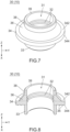
Fig. 7 is a perspective view showing a bushing of the seal structure ofFig. 3 . -
Fig. 8 is a partially cut-away, perspective view showing the bushing ofFig. 7 , wherein imaginary boundary lines among parts of the bushing are illustrated with dashed line. -
Fig. 9 is a front view showing the bushing ofFig. 7 . -
Fig. 10 is a cross-sectional view showing the bushing ofFig. 8 , wherein imaginary boundary lines among parts of the bushing are illustrated with dashed line. -
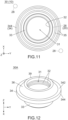
Fig. 11 is a bottom view showing the bushing ofFig. 7 , wherein a position of an introducing hole and positions of screw holes relative to the bushing of the seal structure under an assembled state shown inFig. 1 are illustrated with dashed line. -
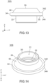
Fig. 12 is a perspective view showing a modification of the bushing ofFig. 7 . -
Fig. 13 is a front view showing the bushing ofFig. 12 . -
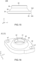
Fig. 14 is a perspective view showing another modification of the bushing ofFig. 7 . -
Fig. 15 is a front view showing the bushing ofFig. 14 . -
Fig. 16 is a perspective view showing a holder of the seal structure ofFig. 3 . -
Fig. 17 is a bottom view showing the holder ofFig. 16 . -
Fig. 18 is a partially cut-away, perspective view showing the holder ofFig. 16 . -
Fig. 19 is a cross-sectional view showing the holder ofFig. 18 . -
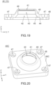
Fig. 20 is a perspective view showing a modification of the holder ofFig. 16 . -
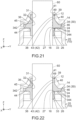
Fig. 21 is a cross-sectional view partially showing the seal structure ofFig. 3 , taken along a plane which includes a center axis of the cable and is perpendicular to a front-rear direction, wherein the seal structure is under a half-assembled state. -
Fig. 22 is a cross-sectional view showing the seal structure ofFig. 21 , wherein the seal structure is under the assembled state. -
Fig. 23 is a partially cut-away, perspective view showing a seal structure of Patent Document 1. - Referring to
Figs. 1 and 2 , aseal structure 10 of an embodiment of the present invention is a seal structure configured to be attached to acable 60. Thecable 60 of the present embodiment extends along an up-down direction and has a circular shape in a horizontal plane perpendicular to the up-down direction. The up-down direction of the present embodiment is the Z-direction. In the present embodiment, "upward" means the positive Z-direction, and "downward" means the negative Z-direction. The horizontal plane of the present embodiment is the XY-plane. The words such as the up-down direction and the horizontal plane do not indicate the absolute positional relation relative to the ground but merely indicate a relative positional relation under a definition in which an extending direction of thecable 60 attached to theseal structure 10 is the up-down direction. - The
cable 60 of the present embodiment comprises asheath 62 made of insulator and a plurality of wires (not shown). Each of the wires has a core wire (not shown) made of conductor and a coat (not shown) made of insulator and covering the core wire. The wires are enclosed by thesheath 62 in the horizontal plane. Thecable 60 has a lower end part thereof where thesheath 62 is removed and the wires are exposed outward from thesheath 62. Thesheath 62 of the present embodiment is made of flexible material. Thus, thecable 60 of the present embodiment is relatively soft and is easily deformed when receiving a force. - The
cable 60 of the present embodiment is a so-called cabtire cable which has the aforementioned configuration. However, thecable 60 of the present invention is not limited to the cabtire cable. The configuration of thecable 60 can be modified as necessary. For example, thesheath 62 may be made of hard material. The number of the wires is not specifically limited. - Referring to
Fig. 2 , theseal structure 10 of the present embodiment includes aconnector 70 incorporated therein. Theconnector 70 comprises a plurality ofterminals 72. Theseal structure 10 is attached to thecable 60 so that the lower end part of thecable 60 is covered by theseal structure 10. The wires (not shown) of the lower end part of thecable 60 are connected to theterminals 72 of theconnector 70, respectively, when theseal structure 10 is attached to thecable 60. - Referring to
Figs. 1 and 2 , theseal structure 10 is configured to be fixed and attached to an object 80 under a state where theseal structure 10 is attached to thecable 60. The object 80 of the present embodiment comprises amating connector 84 and a board 82 which is incorporated in a mating device (not shown). Themating connector 84 is fixed on the board 82. Themating connector 84 comprises a plurality of mating terminals (not shown) and a plurality ofmating wires 88 which are connected to the mating terminals, respectively. The object 80 of the present embodiment has the aforementioned configuration. However, the configuration of the object 80 of the present invention is not specifically limited. - The
seal structure 10 of the present embodiment is configured to be fixed to themating connector 84. When theseal structure 10 is fixed to themating connector 84, theconnector 70 is mated with themating connector 84, and the wires (not shown) of thecable 60 are electrically connected with themating wires 88 via theterminals 72 and the mating terminals (not shown). Meanwhile, a lower end of theseal structure 10 is pressed against and is in secure contact with an upper surface of themating connector 84, and the lower end part of thecable 60 is sealed in theseal structure 10. Thus, thecable 60 is connected to the mating device (not shown) via theseal structure 10, and theseal structure 10 provides a sealing function such as a waterproof function and a foreign-substance-invasion prevention function. - The
seal structure 10 of the present embodiment is configured to be attached to thecable 60 and the object 80 as described above. For example, the object 80 is a part of the mating device (not shown) which is used in a food factory. The mating device and theseal structure 10 of this instance may be disinfected with hot steam having high-pressure. As described later, theseal structure 10 of the present embodiment is suitable for such usage. However, the usage of theseal structure 10 of the present invention is not specifically limited. The configuration of theseal structure 10 can be modified in accordance with the usage of theseal structure 10. - Referring to
Fig. 3 , theseal structure 10 of the present embodiment comprises ahood 20, abushing 30 and aholder 40 in addition to theconnector 70. Theseal structure 10 can be assembled as described below. Firstly, thehood 20, thebushing 30 and theholder 40 are arranged in this order from bottom and are combined together. Then, thehood 20 is fixed to theholder 40 with twoscrews 52. Under an assembled state where theseal structure 10 attached to thecable 60 is assembled as shown inFigs. 1 and 2 , thebushing 30 is located in thehood 20 and theholder 40 and is invisible from the outside. Theseal structure 10 under the assembled state can be fixed to the object 80 (seeFigs. 1 and 2 ) with twoscrews 54. - The
seal structure 10 of the present embodiment has the aforementioned configuration. However, the present invention is not limited thereto. For example, the connector 70 (seeFig. 2 ) may be provided as necessary. Theseal structure 10 may further comprise another member in addition to the aforementioned members. - Hereafter, explanation will be made about the
hood 20 of the present embodiment. - Referring to
Figs. 4 and5 , thehood 20 of the present embodiment is made of hard material such as resin and has amain portion 21 and anattachment portion 24. Themain portion 21 and theattachment portion 24 are integrally formed with each other. Thehood 20 is formed with anaccommodation portion 23. Theaccommodation portion 23 is a space in which the connector 70 (seeFig. 2 ) is arranged. Theaccommodation portion 23 is enclosed by themain portion 21 in the horizontal plane with no gap and opens downward. - The
attachment portion 24 of the present embodiment is located at an upper end of thehood 20 and has a rectangular flat-plate shape in parallel to the horizontal plane. Theattachment portion 24 covers theaccommodation portion 23 from above. Theattachment portion 24 is formed with an introducinghole 26. The introducinghole 26 is located at the middle of theattachment portion 24 in the horizontal plane and has a circular shape in the horizontal plane. The introducinghole 26 passes through theattachment portion 24 in the up-down direction. The thus-formed introducinghole 26 communicates with theaccommodation portion 23 in the up-down direction. In other words, theaccommodation portion 23 opens upward through the introducinghole 26. Referring toFig. 3 , the introducinghole 26 has a size larger than that of thecable 60 in the horizontal plane. - As shown in
Figs. 4 and5 , the introducinghole 26 of thehood 20 of the present embodiment has an upper edge which is provided with a chamferedportion 27. The chamferedportion 27 encloses the introducinghole 26 in the horizontal plane and extends upward while spreading outward in the horizontal plane. - The
attachment portion 24 of thehood 20 of the present embodiment is formed with two screw holes 28. The screw holes 28 are located at two of four corners of theattachment portion 24, respectively, the two of the four corners being not adjacent to each other. The thus-formed twoscrew holes 28 are located at opposite corners, respectively, with the introducinghole 26 located therebetween in the horizontal plane. Referring toFig. 6 , each of the screw holes 28 is a hole with its bottom. In other words, each of the screw holes 28 is unconnected to theaccommodation portion 23. - As shown in
Figs. 4 and5 , themain portion 21 of the present embodiment is provided with two projectingportions 22. The projectingportions 22 are located at a lower end of themain portion 21 in the up-down direction and are located at opposite sides of themain portion 21, respectively, in a lateral direction perpendicular to the up-down direction. The projectingportions 22 are located at the middle of themain portion 21 in a front-rear direction perpendicular to both the up-down direction and the lateral direction. Each of the projectingportions 22 projects outward from themain portion 21 in the lateral direction. The lateral direction of the present embodiment is the Y-direction. The front-rear direction of the present embodiment is the X-direction. In the present embodiment, "forward" means the positive X-direction, and "rearward" means the negative X-direction. - Each of the projecting
portions 22 is formed with a fixinghole 29. Each of the fixing holes 29 passes through the projectingportion 22 in the up-down direction. Referring toFigs. 3 and5 together withFig. 1 , thehood 20 is configured to be fixed to the object 80 by screwing thescrews 54 into themating connector 84 of the object 80 through the fixing holes 29. The lower end of the thus-fixedhood 20 is brought into secure contact with themating connector 84. The fixing method using thescrews 54 is simple and secure. However, the method of fixing thehood 20 to the object 80 of the present invention is not specifically limited. - The
hood 20 of the present embodiment has the aforementioned configuration. However, the present invention is not limited thereto. The configuration of thehood 20 can be modified as necessary, provided that thehood 20 is provided with theattachment portion 24 formed with the introducinghole 26. - Hereafter, explanation will be made about the
bushing 30 of the present embodiment. - Referring to
Figs. 7 to 10 , thebushing 30 of the present embodiment is made of elastomer such as rubber and has alower tube 33, aflange 34, a taperedportion 36 and anupper tube 38. Thebushing 30 is elastically deformed easily when a force is applied to thebushing 30. The elasticallydeformed bushing 30 has a restoring force which tries to return thebushing 30 to its original shape. - The
lower tube 33 is a lower end part of thebushing 30 and has a cylindrical shape. Thelower tube 33 extends downward from theflange 34. In other words, theflange 34 is located above thelower tube 33. Theflange 34 has a circular ring shape and protrudes outward in the horizontal plane beyond an outer surface of thelower tube 33 in the horizontal plane. The taperedportion 36 has a hollow, truncated cone shape. The taperedportion 36 extends upward from theflange 34 while being tapered. Theupper tube 38 is an upper end part of thebushing 30 and has a cylindrical shape. Theupper tube 38 extends upward from the taperedportion 36. Theupper tube 38 has anupper end 39 which is located at the upper end of thebushing 30. - The
bushing 30 of the present embodiment has the aforementioned portions. However, the present invention is not limited thereto. For example, thelower tube 33 and theupper tube 38 may be provided as necessary. The shape of each of theflange 34 and the taperedportion 36 is not specifically limited, provided that the taperedportion 36 is tapered upward, and that theflange 34 protrudes from a lower end of the taperedportion 36 in the horizontal plane. Thebushing 30 may further have another portion in addition to the aforementioned portions. - Referring to
Figs. 7, 8 and10 , thebushing 30 is formed with a holdinghole 31. The holdinghole 31 is a cylindrical space and is located at the middle of thebushing 30 in the horizontal plane. The holdinghole 31 is enclosed by thelower tube 33, theflange 34, the taperedportion 36 and theupper tube 38 in the horizontal plane with no gap and opens upward and downward. In other words, the holdinghole 31 passes through thebushing 30 in the up-down direction. Referring toFig. 3 , the holdinghole 31 has a size same as that of thecable 60 in the horizontal plane. - Referring to
Figs. 8 and10 , the inner wall of the holdinghole 31 of the present embodiment is provided with twoinner libs 32. Each of theinner libs 32 has a ring-like shape in parallel to the horizontal plane and encloses the holdinghole 31 in the horizontal plane. The twoinner libs 32 are vertically arranged. The upperinner lib 32 is located at a position which corresponds to the taperedportion 36 in the up-down direction and projects inward in the horizontal plane. The lowerinner lib 32 is located at a position which corresponds to theflange 34 in the up-down direction and projects inward in the horizontal plane. - Referring to
Figs. 8 and11 , theflange 34 has anupper surface 342 and alower surface 344. Each of theupper surface 342 and thelower surface 344 of the present embodiment is a flat surface in parallel to the horizontal plane. Referring toFigs. 10 and11 , thelower surface 344 of the present embodiment is provided with twolibs 35. Each of thelibs 35 has a ring-like shape and projects downward. In detail, each of thelibs 35 has a ring-like shape located around the holdinghole 31 in the horizontal plane. One of thelibs 35 encloses a remaining one of thelibs 35 in the horizontal plane. - The
bushing 30 of the present embodiment has the aforementioned configuration. However, the present invention is not limited thereto. The configuration of thebushing 30 can be modified as necessary, provided that thebushing 30 is provided with theflange 34 and the taperedportion 36 in which the holdinghole 31 is formed. - Hereafter, explanation will be made about the holder 40 (see
Fig. 3 ) of the present embodiment. - Referring to
Figs. 16 ,18 and19 , theholder 40 of the present embodiment is made of hard material such as resin and has an attachedportion 46, an enclosingportion 48 and acover 49. The attachedportion 46, the enclosingportion 48 and thecover 49 are integrally molded with each other. Theholder 40 is formed with acavity 42. Thecavity 42 is a space configured to receive the bushing 30 (seeFig. 3 ). Thecavity 42 is enclosed by the attachedportion 46 and the enclosingportion 48 in the horizontal plane with no gap and opens downward. - The attached
portion 46 of the present embodiment is located at the lower end of theholder 40 and has a flat-plate shape in parallel to the horizontal plane. The enclosingportion 48 has a hollow, truncated cone shape and extends upward from the attachedportion 46 while being tapered. Thecover 49 is located at the upper end of theholder 40 and has a circular ring shape in parallel to the horizontal plane. Thecover 49 extends inward in the horizontal plane from the upper end of the enclosingportion 48. - The
cover 49 covers thecavity 42 from above. Thecover 49 is formed with a passinghole 41. Thus, theholder 40 is formed with the passinghole 41. The passinghole 41 of the present embodiment is located at the middle of thecover 49 in the horizontal plane and has a circular shape in the horizontal plane. The passinghole 41 passes through thecover 49 in the up-down direction and communicates with thecavity 42. In other words, thecavity 42 opens upward through the passinghole 41. Referring toFig. 3 , the passinghole 41 has a size same as that of thecable 60 in the horizontal plane. - Referring to
Figs. 16 to 19 , the attachedportion 46 is formed with two fixingholes 47. Each of the fixing holes 47 passes through the attachedportion 46 in the up-down direction. The two fixingholes 47 are located on opposite sides of theholder 40 in the horizontal plane, respectively, with the enclosingportion 48 located therebetween. More specifically, referring toFig. 3 , the two fixingholes 47 are located at positions which correspond to the twoscrew holes 28 of thehood 20 in the horizontal plane, respectively. As described later, the fixing holes 47 and the screw holes 28 are portions for fixing theholder 40 to thehood 20. - As shown in
Figs. 17 to 19 , theholder 40 has a firstpressing portion 44 and a secondpressing portion 45. Each of the first pressingportion 44 and the secondpressing portion 45 is a surface of an inner wall which encloses thecavity 42. Thus, the first pressingportion 44 and the secondpressing portion 45 are provided on an inner surface of thecavity 42. The firstpressing portion 44 is a lower surface of a part of the attachedportion 46 which is located between the enclosingportion 48 and the fixing holes 47 in the horizontal plane. The firstpressing portion 44 is a flat surface in parallel to the horizontal plane. The secondpressing portion 45 is an inner surface of the attachedportion 46 in the horizontal plane. The secondpressing portion 45 has a truncated cone shape and extends upward from an inner edge of the first pressingportion 44 in the horizontal plane while being tapered. - Referring to
Fig. 19 , thecavity 42 of theholder 40 of the present embodiment has a receivingportion 43. Thus, theholder 40 is formed with the receivingportion 43. The receivingportion 43 is an upper part of thecavity 42 and is located above the secondpressing portion 45. Referring toFig. 19 together withFig. 10 , the receivingportion 43 is a space configured to receive theupper tube 38 of thebushing 30 and has a cylindrical shape corresponding to theupper tube 38. The receivingportion 43 has a size slightly larger than that of theupper tube 38 in the horizontal plane. - The
holder 40 of the present embodiment has the aforementioned configuration. However, the present invention is not limited thereto. The configuration of theholder 40 can be modified as necessary, provided that theholder 40 has the attachedportion 46, the first pressingportion 44, the secondpressing portion 45 and thecover 49 and is formed with thecavity 42 and the passinghole 41. For example, the receivingportion 43 and the fixing holes 47 may be provided as necessary. - Referring to
Fig. 3 , hereafter, explanation will be made about an assembly method of theseal structure 10 of the present embodiment. The assembly method described below is merely an example and can be modified as necessary. - Firstly, the
hood 20, thebushing 30 and theholder 40 are arranged in this order from bottom in the up-down direction. Then, thecable 60 is arranged so that thecable 60 passes through the passinghole 41 of theholder 40, the holdinghole 31 of thebushing 30 and the introducinghole 26 of thehood 20. Meanwhile, the lower end part of thecable 60 is arranged in the accommodation portion 23 (seeFig. 4 ) of thehood 20. - Then, referring to
Fig. 21 together withFig. 3 , thebushing 30 is received in thecavity 42 of theholder 40. Meanwhile, theupper tube 38 of thebushing 30 is inserted into the receivingportion 43 of thecavity 42. Thebushing 30 can be positioned relative to theholder 40 by inserting theupper tube 38 into the receivingportion 43. Then, thelower tube 33 of thebushing 30 is inserted into the introducinghole 26 of thehood 20. Thebushing 30 and theholder 40 can be positioned relative to thehood 20 by inserting thelower tube 33 into the introducinghole 26. Thecable 60 extends straight in the up-down direction as a result of the aforementioned positioning. After the aforementioned positioning, the attachedportion 46 of theholder 40 faces theattachment portion 24 of thehood 20 in the up-down direction, and theseal structure 10 takes a half-assembled state as shown inFig. 21 . - Summarizing the explanation described above with reference to
Fig. 21 , theseal structure 10 takes the half-assembled state when thebushing 30 is received in thecavity 42 of theholder 40 and the attachedportion 46 of theholder 40 faces theattachment portion 24 of thehood 20 in the up-down direction under a state where thecable 60 passes through the passinghole 41 of theholder 40, the holdinghole 31 of thebushing 30 and the introducinghole 26 of thehood 20. - Lower ends of the
libs 35 of thebushing 30 are in contact with the upper surface of theattachment portion 24 of thehood 20 under the half-assembled state. - Therefore, the
flange 34 of thebushing 30 is located above theattachment portion 24 with a distance formed therebetween which is equal to a size of each of thelibs 35 in the up-down direction. The taperedportion 36 of thebushing 30 is in contact with the secondpressing portion 45 of theholder 40. The thus-arrangedholder 40 is located above theattachment portion 24 with a distance formed therebetween in the up-down direction. - The
seal structure 10 under the half-assembled state is formed with various gaps (spaces). For example, under the half-assembled state, theseal structure 10 is formed with agap 12 which is located between thecover 49 of theholder 40 and theupper tube 38 of thebushing 30 in the up-down direction. According to the present embodiment, the whole of theupper end 39 of theupper tube 38 is located below a lower surface of thecover 49 with a distance formed therebetween. Theseal structure 10 is also formed with agap 14 which spreads above and below theflange 34 of thebushing 30 and spreads outward of theflange 34 in the horizontal plane. Theseal structure 10 is also formed with agap 16 which is located between thelower tube 33 of thebushing 30 and theattachment portion 24 of thehood 20. These gaps may work as invasion paths through which water and foreign substance would enter into thehood 20. - Then, referring to
Figs. 21 and 22 , theholder 40 is pressed against thehood 20 in the up-down direction so that the lower surface of the attachedportion 46 of theholder 40 is brought into secure contact with the upper surface of theattachment portion 24 of thehood 20. Theseal structure 10 takes the assembled state as shown inFig. 22 when the thus-pressedholder 40 is fixed to thehood 20. Thus, theseal structure 10 takes the assembled state when theholder 40 under the half-assembled state is fixed to thehood 20. - Referring to
Fig. 21 together withFig. 3 , according to the present embodiment, theholder 40 under the half-assembled state is configured to be fixed to thehood 20 by screwing thescrews 52 into the screw holes 28 of thehood 20 through the fixing holes 47 of theholder 40. Theholder 40 can be simply and securely fixed to thehood 20 by this screw fixing. However, the present invention is not limited thereto. Referring toFig. 22 , the fixing method of theholder 40 to thehood 20 is not specifically limited, provided that the lower surface of the attachedportion 46 of theholder 40 is pressed against and is in secure contact with the upper surface of theattachment portion 24 of thehood 20 under the assembled state. For example, theholder 40 may be fixed to thehood 20 by a snap lock without using thescrews 52. According to this instance, the fixing holes 47 do not need to be provided. - Referring to
Figs. 21 and 22 , thebushing 30 is elastically deformed under the assembled state where theseal structure 10 attached to thecable 60 is assembled as shown inFig.22 . In detail, the first pressingportion 44 of theholder 40 presses theupper surface 342 of theflange 34 of thebushing 30 downward so that thebushing 30 is elastically deformed. In addition, the secondpressing portion 45 of theholder 40 presses the taperedportion 36 of thebushing 30 downward and inward in the horizontal plane so that thebushing 30 is elastically deformed. The elasticallydeformed bushing 30 is pressed against theholder 40, thehood 20 and thecable 60 by its restoring force. - The tapered
portion 36 of thebushing 30 is compressed in each of the up-down direction and the horizontal plane when thebushing 30 is elastically deformed. As a result, theupper tube 38 of thebushing 30 is stretched in the up-down direction. The thus-elastically deformedupper tube 38 fills thegap 12. In detail, theupper tube 38 is received in the receivingportion 43 of theholder 40 and fills the receivingportion 43 under the assembled state. The thus-receivedupper tube 38 is brought into contact with thecover 49 of theholder 40 under the assembled state. Moreover, theupper tube 38 is pressed against an inner wall surface of theholder 40 and thecable 60 under the assembled state. In addition, theinner libs 32 of thebushing 30 are pressed against thecable 60 under the assembled state. In detail, theinner libs 32 are pressed against thecable 60 while being compressed. As a result, the invasion path of water and foreign substance, which extends along an outer surface of thecable 60 in the horizontal plane, is blocked. - The
flange 34 of thebushing 30 is compressed in the up-down direction and is stretched in the horizontal plane when thebushing 30 is elastically deformed. The thus-elasticallydeformed flange 34 fills a part of thegap 14 which is located between theflange 34 and the attachedportion 46 of theholder 40 in the horizontal plane. In detail, theflange 34 is received in a lower end part of thecavity 42 of theholder 40 and fills the lower end part of thecavity 42 under the assembled state. Thelower surface 344 of theflange 34 is pressed against the upper surface of theattachment portion 24 of thehood 20. In addition, thelibs 35 of theflange 34 are pressed against the upper surface of theattachment portion 24 while being compressed. As a result, the invasion path of water and foreign substance, which passes between theattachment portion 24 and thelower surface 344 of thebushing 30, is blocked. - The
lower tube 33 of thebushing 30 is stretched in each of the up-down direction and the horizontal plane when thebushing 30 is elastically deformed. The thus-elastically deformedlower tube 33 fills thegap 16. In detail, thelower tube 33 is received in the introducinghole 26 of thehood 20 under the assembled state. Meanwhile, thelower tube 33 is stretched as a result of the compression of the taperedportion 36 and theflange 34 and fills the introducinghole 26 under the assembled state. Theflange 34 and thelower tube 33 which are elastically deformed fill the chamferedportion 27 formed around the introducinghole 26. - Summarizing the explanation described above, under the assembled state, the first pressing
portion 44 of theholder 40 is pressed against theupper surface 342 of theflange 34 of thebushing 30, thelower surface 344 of theflange 34 is pressed against theattachment portion 24 of thehood 20, the secondpressing portion 45 of theholder 40 is pressed against the taperedportion 36 of thebushing 30, and the inner wall of the holdinghole 31 of thebushing 30 is pressed against thecable 60. According to this mechanism, the lower end part of thecable 60 received in thehood 20 can be sealed. In addition, thecable 60 can be securely held so that thecable 60 extends straight in the up-down direction. - According to the present embodiment, the
gaps gap 12 may be already filled under the half-assembled state. However, according to this configuration, an excessively large force is required to elastically deform thebushing 30 when thecable 60 is hard. Accordingly, the present embodiment is preferable unless there is specific reason. - According to the present embodiment, the
gaps gaps upper end 39 of theupper tube 38 may be located below thecover 49 of theholder 40 with a distance formed therebetween under the assembled state. - According to the present embodiment, the lower end part of the
cable 60 can be more securely sealed since the twoinner libs 32 and the twolibs 35 are provided. Referring toFig. 22 together withFig. 11 , under the assembled state, thelibs 35 are pressed against a part of theattachment portion 24 which is located between the screw holes 28 and the introducinghole 26 in the horizontal plane. According to this configuration, thelibs 35 can be more securely pressed against theattachment portion 24, and the lower end part of thecable 60 can be more securely sealed. However, the present invention is not limited thereto. For example, the number of theinner libs 32 may be one, three or more. One of theinner libs 32 may be located at a position which corresponds to the taperedportion 36 in the up-down direction. Similarly, the number of thelibs 35 may be one, three or more. Moreover, theinner libs 32 and thelibs 35 may be provided as necessary. - Referring to
Fig. 6 , the screw holes 28 of thehood 20 of the present embodiment are not connected to theaccommodation portion 23 which is an inner space of thehood 20. Therefore, the screw holes 28 do not affect the sealing function of theseal structure 10. - Referring to
Figs. 21 and 22 , the chamferedportion 27 of the present embodiment not only works as a guide portion which guides thelower tube 33 of thebushing 30 when thelower tube 33 is inserted into the introducinghole 26 of thehood 20 but also works as a space which receives a part of the elasticallydeformed flange 34 and a part of the elastically deformedlower tube 33. However, the present invention is not limited thereto. For example, the chamferedportion 27 may be provided as necessary. - Referring to
Fig. 22 , thecover 49 of theholder 40 under the assembled state encloses thecable 60 in the horizontal plane and covers theupper end 39 of thebushing 30 from above. This configuration arranges thebushing 30 so that thebushing 30 is not directly exposed to hot steam even when theseal structure 10 is disinfected with hot steam. Moreover, a part of thebushing 30 which is directly exposed to hot steam can be limited by blocking thegap 12 even when another gap is formed between thecover 49 and the outer surface of thecable 60. The present embodiment provides theseal structure 10 which can prevent degradation of the sealing function of thebushing 30 which might be caused by hot steam. - According to the present embodiment, the
cover 49 of theholder 40 is in contact with thecable 60 in the horizontal plane. This configuration can more reliably prevent degradation of the sealing function of thebushing 30 which might be caused by hot steam. However, this configuration makes it difficult for ahard cable 60 to pass through the passinghole 41 of theholder 40. Considering from another viewpoint, when a large gap is formed between thecover 49 and thecable 60 in the horizontal plane, theupper end 39 of thebushing 30 might be partially deteriorated because of hot steam. However, even if theupper end 39 of thebushing 30 is partially deteriorated, the sealing function is not substantially degraded. Accordingly, from a viewpoint of preventing the deterioration of thebushing 30 as much as possible and making thecable 60 easily pass through the passinghole 41, it is preferable to provide a gap as small as possible between thecover 49 and thecable 60. - The present embodiment can be further variously modified as described below in addition to the already described various modifications.
- Comparing
Figs. 12 and13 withFigs. 7 and9 , abushing 30A according to a first modification does not have theupper tube 38. Thebushing 30A has the configuration same as that of thebushing 30 except for this difference. According to this modification, the taperedportion 36 has theupper end 39 which is the upper end of thebushing 30A. Referring toFig. 12 together withFig. 22 , although thebushing 30A is used instead of thebushing 30, the present modification provides theseal structure 10 which can prevent degradation of the sealing function of thebushing 30A which might be caused by hot steam. However, when thebushing 30A is used, additional modification of the other members such as removal of the receivingportion 43 of theholder 40 should be necessary. - Comparing
Figs. 14 and15 withFigs. 7 and9 , abushing 30B according to a second modification does not have thelower tube 33. Thebushing 30B has the configuration same as that of thebushing 30 except for this difference. Referring toFig. 14 together withFig. 22 , although thebushing 30B is used instead of thebushing 30, the present modification provides theseal structure 10 which can prevent degradation of the sealing function of thebushing 30B which might be caused by hot steam. However, when thebushing 30B is used, additional modification of the other members such as provision of a mechanism which positions thebushing 30B relative to thehood 20 should be necessary. - Referring to
Fig. 7 together withFigs. 12 ,14 and22 , a size of theupper tube 38 in the up-down direction may be made smaller instead of the removal of theupper tube 38. Similarly, a size of thelower tube 33 in the up-down direction may be made smaller instead of the removal of thelower tube 33. Moreover, both theupper tube 38 and thelower tube 33 may be removed. - Comparing
Fig. 20 withFig. 16 , aholder 40C according to a third modification has an attachedportion 46C instead of the attachedportion 46. The attachedportion 46C has a rectangular shape and is formed with four of the fixing holes 47. Theholder 40C has the configuration same as that of theholder 40 except for this difference. Referring toFig. 20 together withFig. 22 , although theholder 40C is used instead of theholder 40, the present modification provides theseal structure 10 which can prevent degradation of the sealing function of thebushing 30 which might be caused by hot steam. Referring toFig. 20 together withFig. 4 , when theholder 40C is used, thehood 20 should be formed with four of the screw holes 28. The sealing function can be made more effective by screwing the four corners of theholder 40C to thehood 20. - Referring to
Fig. 3 , according to the present embodiment, only onecable 60 is attached to theseal structure 10. However, the present invention is not limited thereto. Two or more of thecables 60 may be attached to theseal structure 10. More specifically, thehood 20 may be formed with two or more of the introducing holes 26. According to this instance, theholder 40 may be formed with two or more of the passing holes 41 which correspond to the introducingholes 26, respectively, and two or more of thebushings 30 each formed with the one holdinghole 31 may be provided. According to this instance, theholder 40 may be formed with two or more of thecavities 42 which correspond to thebushings 30, respectively. Instead, two or more of theholders 40 each formed with the one passinghole 41 may be provided, and two or more of thebushings 30 each formed with the one holdinghole 31 may be provided.
Claims (8)
- A seal structure (10) configured to be attached to a cable (60), wherein:the seal structure (10) comprises a hood (20), a bushing (30, 30A, 30B) and a holder (40, 40C);the hood (20) has an attachment portion (24);the attachment portion (24) is formed with an introducing hole (26);the introducing hole (26) passes through the attachment portion (24) in an up-down direction (Z-direction);the bushing (30, 30A, 30B) is made of elastomer and has a flange (34) and a tapered portion (36);the flange (34) has an upper surface (342) and a lower surface (344);the tapered portion (36) extends upward from the flange (34) while being tapered;the bushing (30, 30A, 30B) is formed with a holding hole (31);the holding hole (31) passes through the bushing (30, 30A, 30B) in the up-down direction (Z-direction);the holder (40, 40C) has an attached portion (46, 46C), a first pressing portion (44), a second pressing portion (45) and a cover (49);the holder (40, 40C) is formed with a cavity (42) and a passing hole (41);the passing hole (41) passes through the cover (49) in the up-down direction (Z-direction) and communicates with the cavity (42);the first pressing portion (44) and the second pressing portion (45) are provided on an inner surface of the cavity (42);the seal structure (10) takes a half-assembled state when the bushing (30, 30A, 30B) is received in the cavity (42) of the holder (40, 40C) and the attached portion (46, 46C) of the holder (40, 40C) faces the attachment portion (24) of the hood (20) in the up-down direction (Z-direction) under a state where the cable (60) passes through the passing hole (41) of the holder (40, 40C), the holding hole (31) of the bushing (30, 30A, 30B) and the introducing hole (26) of the hood (20);the seal structure (10) takes an assembled state when the holder (40, 40C) under the half-assembled state is fixed to the hood (20);under the assembled state, the first pressing portion (44) of the holder (40, 40C) is pressed against the upper surface (342) of the flange (34) of the bushing (30, 30A, 30B), the lower surface (344) of the flange (34) is pressed against the attachment portion (24) of the hood (20), the second pressing portion (45) of the holder (40, 40C) is pressed against the tapered portion (36) of the bushing (30, 30A, 30B), an inner wall of the holding hole (31) of the bushing (30, 30A, 30B) is pressed against the cable (60); andthe cover (49) of the holder (40, 40C) under the assembled state encloses the cable (60) in a horizontal plane (XY-plane) perpendicular to the up-down direction (Z-direction) and covers an upper end of the bushing (30, 30A, 30B) from above.
- The seal structure (10) as recited in claim 1, wherein:the bushing (30, 30A, 30B) has an upper tube (38);the upper tube (38) extends upward from the tapered portion (36);the cavity (42) of the holder (40, 40C) has a receiving portion (43); andthe upper tube (38) is received in the receiving portion (43) under the assembled state.
- The seal structure (10) as recited in claim 2, wherein under the half-assembled state, the seal structure (10) is formed with a gap (12) which is located between the cover (49) of the holder (40, 40C) and the upper tube (38) of the bushing (30, 30A, 30B) in the up-down direction (Z-direction).
- The seal structure (10) as recited in claim 2 or 3, wherein the upper tube (38) is brought into contact with the cover (49) under the assembled state.
- The seal structure (10) as recited in one of claims 1 to 4, wherein:the bushing (30, 30A, 30B) has a lower tube (33);the lower tube (33) extends downward from the flange (34); andthe lower tube (33) is received in the introducing hole (26) of the hood (20) under the assembled state.
- The seal structure (10) as recited in claim 5, wherein the introducing hole (26) of the hood (20) has an upper edge which is formed with a chamfered portion (27).
- The seal structure (10) as recited in one of claims 1 to 6, wherein:the lower surface (344) of the flange (34) of the bushing (30, 30A, 30B) is provided with a lib (35);the lib (35) has a ring-like shape and projects downward;the attachment portion (24) of the hood (20) is formed with a screw hole (28);the holder (40, 40C) under the half-assembled state is configured to be fixed to the hood (20) by screwing a screw into the screw hole (28); andunder the assembled state, the lib (35) is pressed against a part of the attachment portion (24) which is located between the screw hole (28) and the introducing hole (26) in the horizontal plane (XY-plane).
- The seal structure (10) as recited in one of claims 1 to 7, wherein:the inner wall of the holding hole (31) of the bushing (30, 30A, 30B) is provided with an inner lib (32);the inner lib (32) is located at a position which corresponds to the tapered portion (36) in the up-down direction (Z-direction) and projects inward in the horizontal plane (XY-plane); andthe inner lib (32) is pressed against the cable (60) under the assembled state.
Applications Claiming Priority (1)
| Application Number | Priority Date | Filing Date | Title |
|---|---|---|---|
| JP2023171566A JP2025062465A (en) | 2023-10-02 | 2023-10-02 | Seal structure |
Publications (1)
| Publication Number | Publication Date |
|---|---|
| EP4535376A1 true EP4535376A1 (en) | 2025-04-09 |
Family
ID=92894742
Family Applications (1)
| Application Number | Title | Priority Date | Filing Date |
|---|---|---|---|
| EP24201513.9A Pending EP4535376A1 (en) | 2023-10-02 | 2024-09-20 | Seal structure |
Country Status (2)
| Country | Link |
|---|---|
| EP (1) | EP4535376A1 (en) |
| JP (1) | JP2025062465A (en) |
Citations (5)
| Publication number | Priority date | Publication date | Assignee | Title |
|---|---|---|---|---|
| US20020023769A1 (en) * | 1998-03-18 | 2002-02-28 | Olivier Pioch | Busbar bushing device and bar lead-in |
| JP2004159459A (en) * | 2002-11-07 | 2004-06-03 | Matsushita Electric Ind Co Ltd | Cable bush |
| JP2018102114A (en) | 2016-11-28 | 2018-06-28 | タイコ エレクトロニクス (シャンハイ) カンパニー リミテッド | Seal assembly |
| EP3396798A1 (en) * | 2017-04-25 | 2018-10-31 | Corning Research & Development Corporation | Sealing body for telecommunication cables |
| CN116157301A (en) * | 2020-08-13 | 2023-05-23 | 自动电缆管理有限公司 | Seals for cables |
-
2023
- 2023-10-02 JP JP2023171566A patent/JP2025062465A/en active Pending
-
2024
- 2024-09-20 EP EP24201513.9A patent/EP4535376A1/en active Pending
Patent Citations (5)
| Publication number | Priority date | Publication date | Assignee | Title |
|---|---|---|---|---|
| US20020023769A1 (en) * | 1998-03-18 | 2002-02-28 | Olivier Pioch | Busbar bushing device and bar lead-in |
| JP2004159459A (en) * | 2002-11-07 | 2004-06-03 | Matsushita Electric Ind Co Ltd | Cable bush |
| JP2018102114A (en) | 2016-11-28 | 2018-06-28 | タイコ エレクトロニクス (シャンハイ) カンパニー リミテッド | Seal assembly |
| EP3396798A1 (en) * | 2017-04-25 | 2018-10-31 | Corning Research & Development Corporation | Sealing body for telecommunication cables |
| CN116157301A (en) * | 2020-08-13 | 2023-05-23 | 自动电缆管理有限公司 | Seals for cables |
Also Published As
| Publication number | Publication date |
|---|---|
| JP2025062465A (en) | 2025-04-14 |
Similar Documents
| Publication | Publication Date | Title |
|---|---|---|
| US9997858B2 (en) | Electrical connector with detachable connecting terminals | |
| US4913664A (en) | Miniature circular DIN connector | |
| US6143987A (en) | Structure for waterproofing an end portion of a cable | |
| JP5799965B2 (en) | Floating connector | |
| KR101168093B1 (en) | Connector and cable retainer | |
| US20180054020A1 (en) | Waterproof connector | |
| US6059594A (en) | Sealed electrical connector | |
| EP2610975A1 (en) | Wire fixing member and method of assembling it | |
| KR20190137962A (en) | Connector assembly | |
| US20130171854A1 (en) | Waterproof Connector and Waterproof Connector Mounting Structure and Mounting Method | |
| US10714868B2 (en) | Waterproof connector for a board | |
| JP2011258557A (en) | Photovoltaic module connector assemblies having cable strain relief | |
| KR101546318B1 (en) | Connector for Connecting Device and the Method for Manufacturing the Connector | |
| JP2018170195A (en) | Electronic components and connectors | |
| CN113745905A (en) | Connector device and connector floating module | |
| US11493698B2 (en) | Optical connector-incorporating plug manufacturing method and optical connector-incorporating plug | |
| US20030032321A1 (en) | Sealed connector | |
| KR100800790B1 (en) | Housing assembly and shield connector having same | |
| JP3954832B2 (en) | Optical connector shield structure | |
| US6840681B2 (en) | Tandem type optical connector | |
| JPH07296879A (en) | Electrical connector | |
| US7347730B2 (en) | Grommet | |
| KR102592289B1 (en) | Cable connector | |
| US20240170877A1 (en) | Connector | |
| JP2023159884A (en) | Connector assemblies including connectors and connectors |
Legal Events
| Date | Code | Title | Description |
|---|---|---|---|
| PUAI | Public reference made under article 153(3) epc to a published international application that has entered the european phase |
Free format text: ORIGINAL CODE: 0009012 |
|
| STAA | Information on the status of an ep patent application or granted ep patent |
Free format text: STATUS: THE APPLICATION HAS BEEN PUBLISHED |
|
| AK | Designated contracting states |
Kind code of ref document: A1 Designated state(s): AL AT BE BG CH CY CZ DE DK EE ES FI FR GB GR HR HU IE IS IT LI LT LU LV MC ME MK MT NL NO PL PT RO RS SE SI SK SM TR |
|
| STAA | Information on the status of an ep patent application or granted ep patent |
Free format text: STATUS: REQUEST FOR EXAMINATION WAS MADE |
|
| 17P | Request for examination filed |
Effective date: 20250728 |
|
| STAA | Information on the status of an ep patent application or granted ep patent |
Free format text: STATUS: EXAMINATION IS IN PROGRESS |
|
| 17Q | First examination report despatched |
Effective date: 20251014 |
|
| GRAP | Despatch of communication of intention to grant a patent |
Free format text: ORIGINAL CODE: EPIDOSNIGR1 |
|
| STAA | Information on the status of an ep patent application or granted ep patent |
Free format text: STATUS: GRANT OF PATENT IS INTENDED |
|
| INTG | Intention to grant announced |
Effective date: 20260310 |
|
| GRAJ | Information related to disapproval of communication of intention to grant by the applicant or resumption of examination proceedings by the epo deleted |
Free format text: ORIGINAL CODE: EPIDOSDIGR1 |
|
| STAA | Information on the status of an ep patent application or granted ep patent |
Free format text: STATUS: EXAMINATION IS IN PROGRESS |
|
| GRAP | Despatch of communication of intention to grant a patent |
Free format text: ORIGINAL CODE: EPIDOSNIGR1 |
|
| STAA | Information on the status of an ep patent application or granted ep patent |
Free format text: STATUS: GRANT OF PATENT IS INTENDED |
|
| INTC | Intention to grant announced (deleted) |