EP4535335A1 - Technique simulator and technique-training method - Google Patents
Technique simulator and technique-training method Download PDFInfo
- Publication number
- EP4535335A1 EP4535335A1 EP23831151.8A EP23831151A EP4535335A1 EP 4535335 A1 EP4535335 A1 EP 4535335A1 EP 23831151 A EP23831151 A EP 23831151A EP 4535335 A1 EP4535335 A1 EP 4535335A1
- Authority
- EP
- European Patent Office
- Prior art keywords
- blood vessel
- puncture
- vessel tube
- puncture block
- technique
- Prior art date
- Legal status (The legal status is an assumption and is not a legal conclusion. Google has not performed a legal analysis and makes no representation as to the accuracy of the status listed.)
- Pending
Links
Images





Classifications
-
- G—PHYSICS
- G09—EDUCATION; CRYPTOGRAPHY; DISPLAY; ADVERTISING; SEALS
- G09B—EDUCATIONAL OR DEMONSTRATION APPLIANCES; APPLIANCES FOR TEACHING, OR COMMUNICATING WITH, THE BLIND, DEAF OR MUTE; MODELS; PLANETARIA; GLOBES; MAPS; DIAGRAMS
- G09B23/00—Models for scientific, medical, or mathematical purposes, e.g. full-sized devices for demonstration purposes
- G09B23/28—Models for scientific, medical, or mathematical purposes, e.g. full-sized devices for demonstration purposes for medicine
- G09B23/285—Models for scientific, medical, or mathematical purposes, e.g. full-sized devices for demonstration purposes for medicine for injections, endoscopy, bronchoscopy, sigmoidscopy, insertion of contraceptive devices or enemas
-
- G—PHYSICS
- G09—EDUCATION; CRYPTOGRAPHY; DISPLAY; ADVERTISING; SEALS
- G09B—EDUCATIONAL OR DEMONSTRATION APPLIANCES; APPLIANCES FOR TEACHING, OR COMMUNICATING WITH, THE BLIND, DEAF OR MUTE; MODELS; PLANETARIA; GLOBES; MAPS; DIAGRAMS
- G09B23/00—Models for scientific, medical, or mathematical purposes, e.g. full-sized devices for demonstration purposes
- G09B23/28—Models for scientific, medical, or mathematical purposes, e.g. full-sized devices for demonstration purposes for medicine
- G09B23/30—Anatomical models
Definitions
- the present invention relates to a technique simulator and a technique training method used for training in a technique using a catheter.
- a technique of inserting a catheter or a sheath into a blood vessel has been widely performed.
- Such catheter puncture is performed on a site where the burden on the patient is small.
- the catheter is often introduced through a radial artery in a wrist (radial artery approach).
- a technique simulator described in WO 2015/146273 A has been proposed.
- a distal radial artery approach has been proposed as a less invasive method.
- the catheter is introduced further distally (peripherally) than the puncture position in the conventional radial artery approach.
- the distal radial artery approach has a lower risk of a hemorrhagic complication, a shorter hemostasis time, and less pain than the conventional radial artery approach.
- the distal radial artery approach has not been widely used because puncturing is difficult due to a small diameter of the target blood vessel, and the approach is a new technique and it has not been long since the proposal.
- a technique simulator that enables a user to easily experience the distal radial artery approach is required.
- An object of the present invention is to solve the aforementioned problems.
- One aspect of the following disclosure is a technique simulator for training in puncture of a distal radial artery of a human body with a medical instrument, the technique simulator including a model main body which imitates an appearance of a hand and a forearm of the human body, a recess portion which is obtained by cutting out in a recessed shape a part of a dorsal portion of the hand, including a snuffbox, of the model main body, a groove portion which extends to a proximal side from the recess portion of the model main body, a puncture block which is fitted into the recess portion to fill the recess portion, and a blood vessel tube a part of which is inserted in an inside of the puncture block and another part of which is inserted in the groove portion, in which the groove portion is opened outward and enables an inside of the blood vessel tube to be visually recognized from an outside.
- Another aspect is a technique training method using the technique simulator according to the aforementioned aspect, the technique training method including a step of checking a position of the blood vessel tube inside the puncture block, a step of puncturing the blood vessel tube with a puncture needle by introducing the puncture needle into a surface of the puncture block, and a step of inserting a guide wire into the blood vessel tube and moving the guide wire forward inside the blood vessel tube arranged in the groove portion.
- the technique simulator and the technique training method of the aforementioned aspects enable the user to easily experience the distal radial artery approach, and thus can contribute to the spread of the distal radial artery approach.
- the radial artery is an artery that branches from the brachial artery (not illustrated) and runs along the radius in the forearm.
- the radial artery runs in a shallow portion close to the skin on the palm side and the thumb side near the wrist. This portion is a portion to be touched with a finger when taking a pulse.
- the puncture position in the conventional radial artery approach is located slightly to the proximal side of the radial artery near the wrist.
- the distal side (peripheral side) of the radial artery passes through a site called a snuffbox (anatomical snuffbox or tabatiere) and goes to the dorsal side of the hand as illustrated in the figure.
- the snuffbox is a portion of a depression that appears from the wrist joint to a portion near the base of the thumb when the thumb is bent outward.
- the snuffbox is a triangular region formed between a portion raised by the extensor pollicis longus tendon located on the dorsal side (back side) of the hand and a portion raised by the extensor pollicis brevis tendon located on the edge side of the hand, and tapered toward the fingertip side.
- the radial styloid process is one of marks for the puncture position in the distal radial artery approach.
- the radial artery extends in a deeper portion than the extensor pollicis longus tendon and the extensor pollicis brevis tendon while crossing the extensor pollicis longus tendon and the extensor pollicis brevis tendon.
- the puncture position in the distal radial artery approach is the radial artery passing through the snuffbox or the radial artery slightly distal to the snuffbox.
- the technique simulator 10 is used for practice of puncturing a puncture position in the distal radial artery approach with a catheter using a model main body 12 imitating a part of a forearm 12a and a hand 12b.
- the technique simulator 10 includes the model main body 12, a puncture block 14, a blood vessel tube 16, a syringe 18, and a table 20.
- the model main body 12 has an outer shape imitating the hand 12b of a human body and a part of the forearm 12a on the distal side.
- the model main body 12 is integrally formed using a resin material.
- the model main body 12 further includes a groove portion 22 and a recess portion 24.
- the groove portion 22 is a recessed groove extending in the extending direction of the hand 12b (proximal and distal directions).
- the groove portion 22 extends to both the proximal side and the distal side of the recess portion 24, and houses and holds the blood vessel tube 16 protruding from the recess portion 24 to the proximal side and the distal side.
- the groove portion 22 has a dimension (width) in a direction orthogonal to the center line in the extending direction smaller than the outside diameter of the blood vessel tube 16, and the blood vessel tube 16 is tightly held so as to be pressed from the width direction and inserted in the groove portion 22.
- the blood vessel tube 16 is made of a member having transparency.
- the blood vessel tube 16 is held by the groove portion 22 so as not to move out of the groove portion 22.
- the groove portion 22 is opened outward (upward) and facilitates visual recognition of the inside of the blood vessel tube 16 from above.
- a portion held in the groove portion 22 when the model is used is referred to as a visible portion 16b
- a portion buried in the puncture block 14 is referred to as a buried portion 16a.
- the buried portion 16a and the visible portion 16b do not represent specific positions in the blood vessel tube 16 itself, and are merely defined by the relationship of the blood vessel tube 16 with the groove portion 22 and the puncture block 14.
- the recess portion 24 houses and holds the puncture block 14.
- the recess portion 24 is a recess having a shape obtained by cutting out a portion of the model main body 12 provided with a snuffbox 26 (refer to Fig. 2 ) and a peripheral portion thereof into a half moon shape in plan view in a case where the model main body 12 is placed with the thumb located on the upper side (hereinbelow, the definition of the plan view is the same as the above definition).
- the recess portion 24 has a straight dorsal side surface 24a located on the dorsal side of the hand 12b and an arc-like side surface 24b located on the palm side.
- the dorsal side surface 24a extends in a straight form in plan view and abuts on a flat portion 14a of the puncture block 14 described below. Since the direction in which the puncture block 14 is fitted into the model main body 12 is determined by providing the dorsal side surface 24a, the puncture block 14 can be positioned in the rotational direction.
- a first merging portion 24c is formed on the proximal side of the arc-like side surface 24b.
- a first portion 22a of the groove portion 22 on the proximal side is connected to the first merging portion 24c.
- a second merging portion 24d is formed on the distal side of the arc-like side surface 24b.
- a second portion 22b of the groove portion 22 on the distal side is connected to the second merging portion 24d.
- the model main body 12 has a simulated protrusion 40 that simulates a protrusion near the wrist due to the radial styloid process at a portion adjacent to the proximal side of the recess portion 24.
- the simulated protrusion 40 is arranged adjacent to the proximal side of the snuffbox 26.
- the simulated protrusion 40 is made of a hard material and buried in the model main body 12, and serves as one of marks for specifying a puncture position.
- the puncture block 14 has an arc-like portion 14b and a flat portion 14a, and has a shape obtained by cutting out a cylinder in the height direction so that the bottom surface of the cylinder has a half moon shape.
- the arc-like portion 14b is a portion having an arc shape in plan view, and corresponds to a side surface of the cylinder after the cylinder is cut out.
- the flat portion 14a has a straight form in plan view and corresponds to a cut surface in a case where the cylinder is cut out.
- the puncture block 14 is formed as a solid mass using an elastic resin material that is softer and more elastic than the model main body 12.
- the puncture block 14 may be formed by cutting out an elastic resin material, or may be molded using a mold having a desired shape.
- the puncture block 14 does not need to have a shape obtained by cutting out the cylinder, and may have any shape that facilitates alignment when the puncture block 14 is fitted into the recess portion 24.
- the puncture block 14 has a slightly larger shape than the recess portion 24 of the model main body 12. As illustrated in Fig. 2 , the puncture block 14 can be fitted into the recess portion 24 while being elastically deformed. When the puncture block 14 is fitted into the recess portion 24, the puncture block 14 completely fills the recess portion 24.
- An upper end surface 14c of the puncture block 14 has substantially the same shape as the outer surface of the hand 12b of the human body. In other words, the upper end surface 14c of the puncture block 14 constitutes a continuous surface with the model main body 12 without excessively protruding from the surface of the model main body 12.
- Examples of the material for the puncture block 14 include elastic materials such as urethane elastomer, natural rubber, and silicone rubber.
- the puncture block 14 is colored in skin color, for example.
- the puncture block 14 is preferably opaque so that the blood vessel tube 16 (buried portion 16a) buried inside the puncture block 14 cannot be visually recognized.
- the puncture block 14 preferably has hardness (elasticity) similar to that of subcutaneous tissue or adipose tissue of the human body, for example.
- Such a puncture block 14 enables a user to feel a similar sense of puncture to that when making a puncture in the target site of the actual human body at the time of puncture with a puncture needle 90 (refer to Fig. 6A ).
- the puncture block 14 includes a first through hole 28, a second through hole 30, and a third through hole 32 therein.
- the first through hole 28 is a hole for housing a first simulated extensor tendon 34 (refer to Fig. 5 ), and is a hole extending substantially parallel to the direction in which the flat portion 14a extends at a certain depth from the upper end surface 14c.
- the first through hole 28 is arranged at a relatively shallow position of about 2 to 3 mm in depth from the upper end surface 14c of the puncture block 14, for example.
- the second through hole 30 is a hole for housing a second simulated extensor tendon 36 (refer to Fig. 5 ), and is arranged at a position closer to the flat portion 14a than the first through hole 28 (that is, on the dorsal side).
- the second through hole 30 is located at the same depth as the first through hole 28.
- the second through hole 30 is inclined with respect to the first through hole 28 so as to approach the first through hole 28 toward the distal side (peripheral side) in plan view.
- the third through hole 32 is a hole through which the blood vessel tube 16 is inserted.
- the blood vessel tube 16 is arranged at a deeper position than the first through hole 28 and the second through hole 30.
- the third through hole 32 is arranged at a position of about 4 mm in depth from the upper end surface 14c of the puncture block 14, for example.
- the third through hole 32 is located on the ventral side (palm side) of the first through hole 28 and the second through hole 30 on the proximal side in plan view, but extends so as to approach the flat portion 14a (that is, go to the dorsal side) toward the distal side.
- the third through hole 32 extends at a deeper position than the first simulated extensor tendon 34 (first through hole 28) and the second simulated extensor tendon 36 (second through hole 30) in plan view while crossing the running directions of the first simulated extensor tendon 34 and the second simulated extensor tendon 36.
- the first simulated extensor tendon 34, the second simulated extensor tendon 36, and the blood vessel tube 16 are attached to the puncture block 14.
- the first simulated extensor tendon 34 is inserted in the first through hole 28.
- the first simulated extensor tendon 34 is an elongated plate-like member imitating the extensor pollicis brevis tendon (refer to Fig. 1 ) of the human body.
- the first simulated extensor tendon 34 is formed to have a length that avoids protrusion from the puncture block 14.
- the first simulated extensor tendon 34 is made of a hard resin member and has hardness that makes it difficult to make a puncture with the puncture needle 90.
- the first simulated extensor tendon 34 has, in the cross section thereof, a raised shape toward the arc-like upper surface side of the puncture block 14.
- the puncture block 14 is configured to enable the raised shape of the first simulated extensor tendon 34 to be easily felt when the user touches the upper end surface 14c.
- the puncture block 14 illustrated in Fig. 5 is fitted into the recess portion 24 as illustrated in Fig. 2 when performing practice.
- the blood vessel tube 16 is inserted in the groove portion 22 of the model main body 12.
- the groove portion 22 is formed to have a width of, for example, about 2 mm, which is smaller than the outside diameter of the blood vessel tube 16. Therefore, the blood vessel tube 16 is held by the groove portion 22 in a stable manner.
- the technique simulator 10 can be used, for example, for practice of puncture by an echo guide method using an echo device (ultrasonic image diagnostic device) (refer to Fig. 6A ).
- the technique simulator 10 can also be used for practice of puncture without using an echo device. In the following description, an example using an echo device will be described.
- the probe 100 is placed on the snuffbox 26.
- the probe 100 is arranged such that its long axis is orthogonal to the extending direction of the blood vessel tube 16.
- the puncture needle 90 (for example, the thickness is 20 G) is arranged in a direction orthogonal to the long axis of the probe 100.
- the puncture needle 90 is introduced from the distal side toward the proximal side along the extending direction of the blood vessel tube 16.
- the puncture with the puncture needle 90 is performed while checking the position of the needle tip of the puncture needle 90 using the echo device.
- the guide wire 92 is inserted into the blood vessel tube 16 as illustrated in Fig. 6B .
- the guide wire 92 travels through the lumen of the blood vessel tube 16. Therefore, it is possible to confirm that the guide wire 92 has been inserted into the blood vessel tube 16 without straying by visually recognizing the blood vessel tube 16 (visible portion 16b) in the groove portion 22.
- the radial artery near the snuffbox has a branch portion to a thin blood vessel. Therefore, in order to avoid accidental insertion into the thin blood vessel, an operation of moving the guide wire 92 forward while rotating the guide wire 92 is required.
- the puncture practice using the technique simulator 10 is completed. If necessary, the above practice may be followed by practice of sheath insertion and catheter insertion.
- the present embodiment relates to a modification example of the puncture block 14 (refer to Fig. 4 ) of the technique simulator 10.
- a puncture block 14A of the present embodiment has a half moon shape obtained by cutting out a side portion of a cylinder.
- the puncture block 14A has similar shape and dimensions to those of the puncture block 14.
- the puncture block 14A is made of a similar elastic resin material to that of the puncture block 14.
- the puncture block 14A includes only the third through hole 32 therein, and the first through hole 28 and the second through hole 30 (refer to Figs. 4 and 5 ) are omitted.
- the puncture block 14A does not have the first simulated extensor tendon 34 and the second simulated extensor tendon 36 (refer to Fig. 5 ).
- the puncture block 14A has two myoid protrusions 35 imitating extensor tendons on the surface of the puncture block 14A.
- the myoid protrusion 35 is a structure that imitates the raised shape of the extensor tendon of the hand, and can notify the user of the position of the extensor tendon.
- the puncture block 14A allows the user to recognize the positions of the extensor tendons even without the first simulated extensor tendon 34 and the second simulated extensor tendon 36, and allows the user to grasp an appropriate puncture position.
- the third through hole 32 is a hole through which the blood vessel tube 16 is inserted.
- the position and shape of the third through hole 32 of the puncture block 14A are similar to the position and shape of the third through hole 32 of the puncture block 14.
- the configuration of the blood vessel tube 16 of the puncture block 14A is similar to that of the blood vessel tube 16 of the puncture block 14.
- the puncture block 14A of the present embodiment is configured as described above. Since the puncture block 14A has the myoid protrusions 35 protruding so as to be raised on the surface, it is possible to allow the user to grasp an appropriate puncture position while simplifying the structure.
- the technique training can also be performed similarly to the case of the first embodiment.
- the manufacturing process for the puncture block 14A can be simplified by eliminating the first simulated extensor tendon 34 and the second simulated extensor tendon 36.
- the puncture block 14A can dispense with replacement work of the simulated extensor tendon, and can save labor for preparation work.
- a technique simulator (10) for training in puncture of a distal radial artery of a human body with a medical instrument includes a model main body (12) which imitates an appearance of a hand (12b) and a forearm (12a) of the human body, a recess portion (24) which is obtained by cutting out in a recessed shape a part of a dorsal portion of the hand, including a snuffbox (26), of the model main body, a groove portion (22) which extends to a proximal side from the recess portion of the model main body, a puncture block (14) which is fitted into the recess portion to fill the recess portion, and a blood vessel tube (16) a part of which is inserted in an inside of the puncture block and another part of which is inserted in the groove portion, in which the groove portion is opened outward and enables an inside of the blood vessel tube to be visually recognized from an outside.
- the technique simulator it is possible to easily perform training of the distal radial artery approach.
- the technique simulator since the technique simulator has the groove portion, the blood vessel tube can be fixed in a stable manner, and an operation of avoiding accidental insertion of a guide wire can be confirmed easily.
- the technique simulator according to item 1 may include a syringe (18) which is connected to an end portion of the blood vessel tube on the proximal side and gives pulsation to a liquid filled inside the blood vessel tube. This technique simulator can reproduce the pulsation of the artery with a simple configuration.
- a width of the groove portion may have a smaller dimension than an outside diameter of the blood vessel tube, and avoid expansion of the blood vessel tube caused by the pulsation by the syringe.
- This technique simulator can reduce the loss of the internal pressure in the blood vessel tube at the time of pulsation and efficiently transmit the pulsation to the blood vessel tube buried in the puncture block.
- the puncture block may include myoid structures that notify a user of positions of two extensor tendons of the hand of the human body, and the blood vessel tube may extend in the puncture block so as to cross the two myoid structures.
- the puncture block may include myoid structures that notify a user of positions of two extensor tendons of the hand of the human body, and the blood vessel tube may extend in the puncture block so as to cross the two myoid structures.
- the two myoid structures may be arranged to penetrate the puncture block and include two simulated extensor tendons (34, 36) imitating extensor tendons of the human body, and the blood vessel tube may extend at a deeper position than the two simulated extensor tendons in the puncture block while crossing the two simulated extensor tendons.
- This technique simulator can reproduce a more natural tactile sensation of the extensor tendon.
- the two myoid structures may include two myoid protrusions (35) protruding from a surface of the puncture block, and the blood vessel tube may extend in the puncture block so as to cross the two myoid protrusions. Since the structure of the puncture block of the technique simulator is simplified, attachment work of the simulated extensor tendon can be dispensed with, manufacturing becomes easy, and handling is excellent.
- the blood vessel tube may include a flexible tube and may slidably be inserted through the puncture block.
- a puncture hole can be removed only by cutting a portion provided with the puncture hole and attaching a sealing cap to the cut portion to seal the portion. Therefore, the technique simulator can decrease the frequency of replacement of the blood vessel tube and can reduce the labor required for practice.
- the puncture block may be made of an opaque elastic material that is softer and more elastic than the model main body. This technique simulator can reproduce a similar sense of puncture to that at the actual puncture position.
- the recess portion and the puncture block may each have a half moon shape obtained by cutting out a part of a circular shape in plan view.
- This technique simulator facilitates positioning when attaching the puncture block to the recess portion and facilitates attachment and detachment of the puncture block.
- the puncture block since the puncture block has a shape obtained by cutting a part of a circle in a straight form in plan view, the puncture block is less likely to be damaged even when the puncture block is removed from the model main body.
- the model main body may include a simulated protrusion (40) protruding from a wrist site to simulate a protrusion of the hand due to a radial styloid process.
- This technique simulator can cause a trainee to grasp a mark in the distal radial artery approach.
- the technique simulator according to any one of items 1 to 10 may include a table (20) which holds the model main body. In this technique simulator, since the model main body is stable, the trainee can concentrate on the practice of puncture.
- a technique training method using the technique simulator according to any one of items 1 to 11 includes a step of checking a position of the blood vessel tube inside the puncture block, a step of puncturing the blood vessel tube with a puncture needle (90) by introducing the puncture needle into a surface of the puncture block, and a step of inserting a guide wire (92) into the blood vessel tube and moving the guide wire forward inside the blood vessel tube arranged in the groove portion.
Landscapes
- Engineering & Computer Science (AREA)
- Physics & Mathematics (AREA)
- General Physics & Mathematics (AREA)
- Health & Medical Sciences (AREA)
- Mathematical Analysis (AREA)
- Pure & Applied Mathematics (AREA)
- Medical Informatics (AREA)
- Algebra (AREA)
- Computational Mathematics (AREA)
- General Health & Medical Sciences (AREA)
- Chemical & Material Sciences (AREA)
- Mathematical Optimization (AREA)
- Mathematical Physics (AREA)
- Medicinal Chemistry (AREA)
- Business, Economics & Management (AREA)
- Educational Administration (AREA)
- Educational Technology (AREA)
- Theoretical Computer Science (AREA)
- Pulmonology (AREA)
- Radiology & Medical Imaging (AREA)
- Instructional Devices (AREA)
Abstract
Description
- The present invention relates to a technique simulator and a technique training method used for training in a technique using a catheter.
- As a part of minimally invasive endovascular treatment, a technique of inserting a catheter or a sheath into a blood vessel has been widely performed. Such catheter puncture is performed on a site where the burden on the patient is small. For example, in cardiac treatment (and examination) using a catheter, the catheter is often introduced through a radial artery in a wrist (radial artery approach). As an instrument for practicing such a radial artery approach, for example, a technique simulator described in
WO 2015/146273 A has been proposed. - In recent years, a distal radial artery approach (dRA) has been proposed as a less invasive method. In the distal radial artery approach, the catheter is introduced further distally (peripherally) than the puncture position in the conventional radial artery approach. The distal radial artery approach has a lower risk of a hemorrhagic complication, a shorter hemostasis time, and less pain than the conventional radial artery approach.
- However, the distal radial artery approach has not been widely used because puncturing is difficult due to a small diameter of the target blood vessel, and the approach is a new technique and it has not been long since the proposal. In order to further spread the distal radial artery approach, a technique simulator that enables a user to easily experience the distal radial artery approach is required.
- An object of the present invention is to solve the aforementioned problems.
- One aspect of the following disclosure is a technique simulator for training in puncture of a distal radial artery of a human body with a medical instrument, the technique simulator including a model main body which imitates an appearance of a hand and a forearm of the human body, a recess portion which is obtained by cutting out in a recessed shape a part of a dorsal portion of the hand, including a snuffbox, of the model main body, a groove portion which extends to a proximal side from the recess portion of the model main body, a puncture block which is fitted into the recess portion to fill the recess portion, and a blood vessel tube a part of which is inserted in an inside of the puncture block and another part of which is inserted in the groove portion, in which the groove portion is opened outward and enables an inside of the blood vessel tube to be visually recognized from an outside.
- Another aspect is a technique training method using the technique simulator according to the aforementioned aspect, the technique training method including a step of checking a position of the blood vessel tube inside the puncture block, a step of puncturing the blood vessel tube with a puncture needle by introducing the puncture needle into a surface of the puncture block, and a step of inserting a guide wire into the blood vessel tube and moving the guide wire forward inside the blood vessel tube arranged in the groove portion.
- The technique simulator and the technique training method of the aforementioned aspects enable the user to easily experience the distal radial artery approach, and thus can contribute to the spread of the distal radial artery approach.
-
-
Fig. 1 is an explanatory view illustrating a radial artery of a hand and a forearm of a human body, a puncture position in a distal radial artery approach, and a puncture position in a conventional radial artery approach. -
Fig. 2 is a perspective view of a technique simulator according to a first embodiment. -
Fig. 3 is a side view in which a puncture block is removed from a model main body inFig. 2 . -
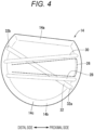
Fig. 4 is a top view of the puncture block inFig. 2 . -
Fig. 5 is a perspective view in which simulated extensor tendons and a blood vessel tube are attached to the puncture block inFig. 2 . -
Fig. 6A is a cross-sectional view illustrating puncture of the blood vessel tube with a puncture needle by an echo guide method in a training method using the technique simulator inFig. 2 , andFig. 6B is a cross-sectional view illustrating an operation of moving a guide wire forward inside the blood vessel tube in the training method using the technique simulator inFig. 2 . -
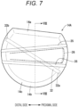
Fig. 7 is a top view of a puncture block according to a second embodiment. -
Fig. 8 is a cross-sectional view taken along line VIII-VIII in the puncture block inFig. 7 . - Prior to description of embodiments, the position of a radial artery in a human body and the puncture position in the distal radial artery approach will be described.
- As illustrated in
Fig. 1 , the radial artery is an artery that branches from the brachial artery (not illustrated) and runs along the radius in the forearm. The radial artery runs in a shallow portion close to the skin on the palm side and the thumb side near the wrist. This portion is a portion to be touched with a finger when taking a pulse. The puncture position in the conventional radial artery approach is located slightly to the proximal side of the radial artery near the wrist. - The distal side (peripheral side) of the radial artery passes through a site called a snuffbox (anatomical snuffbox or tabatiere) and goes to the dorsal side of the hand as illustrated in the figure. The snuffbox is a portion of a depression that appears from the wrist joint to a portion near the base of the thumb when the thumb is bent outward.
- The snuffbox is a triangular region formed between a portion raised by the extensor pollicis longus tendon located on the dorsal side (back side) of the hand and a portion raised by the extensor pollicis brevis tendon located on the edge side of the hand, and tapered toward the fingertip side. There is a protrusion due to the radial styloid process on the proximal side of the snuffbox. The radial styloid process is one of marks for the puncture position in the distal radial artery approach.
- At the snuffbox, the radial artery extends in a deeper portion than the extensor pollicis longus tendon and the extensor pollicis brevis tendon while crossing the extensor pollicis longus tendon and the extensor pollicis brevis tendon. The puncture position in the distal radial artery approach is the radial artery passing through the snuffbox or the radial artery slightly distal to the snuffbox.
- Hereinafter, a
technique simulator 10 according to an embodiment will be described. As illustrated inFig. 2 , thetechnique simulator 10 according to the present embodiment is used for practice of puncturing a puncture position in the distal radial artery approach with a catheter using a modelmain body 12 imitating a part of aforearm 12a and ahand 12b. - As illustrated, the
technique simulator 10 includes the modelmain body 12, apuncture block 14, ablood vessel tube 16, asyringe 18, and a table 20. The modelmain body 12 has an outer shape imitating thehand 12b of a human body and a part of theforearm 12a on the distal side. The modelmain body 12 is integrally formed using a resin material. - The model
main body 12 further includes agroove portion 22 and arecess portion 24. Thegroove portion 22 is a recessed groove extending in the extending direction of thehand 12b (proximal and distal directions). Thegroove portion 22 extends to both the proximal side and the distal side of therecess portion 24, and houses and holds theblood vessel tube 16 protruding from therecess portion 24 to the proximal side and the distal side. Thegroove portion 22 has a dimension (width) in a direction orthogonal to the center line in the extending direction smaller than the outside diameter of theblood vessel tube 16, and theblood vessel tube 16 is tightly held so as to be pressed from the width direction and inserted in thegroove portion 22. Theblood vessel tube 16 is made of a member having transparency. Theblood vessel tube 16 is held by thegroove portion 22 so as not to move out of thegroove portion 22. Thegroove portion 22 is opened outward (upward) and facilitates visual recognition of the inside of theblood vessel tube 16 from above. In theblood vessel tube 16, a portion held in thegroove portion 22 when the model is used is referred to as avisible portion 16b, and a portion buried in thepuncture block 14 is referred to as a buriedportion 16a. Note that the buriedportion 16a and thevisible portion 16b do not represent specific positions in theblood vessel tube 16 itself, and are merely defined by the relationship of theblood vessel tube 16 with thegroove portion 22 and thepuncture block 14. - As illustrated in
Fig. 3 , therecess portion 24 houses and holds thepuncture block 14. Therecess portion 24 is a recess having a shape obtained by cutting out a portion of the modelmain body 12 provided with a snuffbox 26 (refer toFig. 2 ) and a peripheral portion thereof into a half moon shape in plan view in a case where the modelmain body 12 is placed with the thumb located on the upper side (hereinbelow, the definition of the plan view is the same as the above definition). Therecess portion 24 has a straightdorsal side surface 24a located on the dorsal side of thehand 12b and an arc-like side surface 24b located on the palm side. - The
dorsal side surface 24a extends in a straight form in plan view and abuts on aflat portion 14a of thepuncture block 14 described below. Since the direction in which thepuncture block 14 is fitted into the modelmain body 12 is determined by providing thedorsal side surface 24a, thepuncture block 14 can be positioned in the rotational direction. - A first merging
portion 24c is formed on the proximal side of the arc-like side surface 24b. Afirst portion 22a of thegroove portion 22 on the proximal side is connected to the first mergingportion 24c. A second mergingportion 24d is formed on the distal side of the arc-like side surface 24b. Asecond portion 22b of thegroove portion 22 on the distal side is connected to the second mergingportion 24d. - The model
main body 12 has asimulated protrusion 40 that simulates a protrusion near the wrist due to the radial styloid process at a portion adjacent to the proximal side of therecess portion 24. Thesimulated protrusion 40 is arranged adjacent to the proximal side of thesnuffbox 26. Thesimulated protrusion 40 is made of a hard material and buried in the modelmain body 12, and serves as one of marks for specifying a puncture position. - As illustrated in
Fig. 4 , thepuncture block 14 has an arc-like portion 14b and aflat portion 14a, and has a shape obtained by cutting out a cylinder in the height direction so that the bottom surface of the cylinder has a half moon shape. The arc-like portion 14b is a portion having an arc shape in plan view, and corresponds to a side surface of the cylinder after the cylinder is cut out. Theflat portion 14a has a straight form in plan view and corresponds to a cut surface in a case where the cylinder is cut out. Thepuncture block 14 is formed as a solid mass using an elastic resin material that is softer and more elastic than the modelmain body 12. Thepuncture block 14 may be formed by cutting out an elastic resin material, or may be molded using a mold having a desired shape. In addition, thepuncture block 14 does not need to have a shape obtained by cutting out the cylinder, and may have any shape that facilitates alignment when thepuncture block 14 is fitted into therecess portion 24. - The
puncture block 14 has a slightly larger shape than therecess portion 24 of the modelmain body 12. As illustrated inFig. 2 , thepuncture block 14 can be fitted into therecess portion 24 while being elastically deformed. When thepuncture block 14 is fitted into therecess portion 24, thepuncture block 14 completely fills therecess portion 24. Anupper end surface 14c of thepuncture block 14 has substantially the same shape as the outer surface of thehand 12b of the human body. In other words, theupper end surface 14c of thepuncture block 14 constitutes a continuous surface with the modelmain body 12 without excessively protruding from the surface of the modelmain body 12. - Examples of the material for the
puncture block 14 include elastic materials such as urethane elastomer, natural rubber, and silicone rubber. Thepuncture block 14 is colored in skin color, for example. Thepuncture block 14 is preferably opaque so that the blood vessel tube 16 (buriedportion 16a) buried inside thepuncture block 14 cannot be visually recognized. Thepuncture block 14 preferably has hardness (elasticity) similar to that of subcutaneous tissue or adipose tissue of the human body, for example. Such apuncture block 14 enables a user to feel a similar sense of puncture to that when making a puncture in the target site of the actual human body at the time of puncture with a puncture needle 90 (refer toFig. 6A ). - As illustrated in
Fig. 4 , thepuncture block 14 includes a first throughhole 28, a second throughhole 30, and a third throughhole 32 therein. The first throughhole 28 is a hole for housing a first simulated extensor tendon 34 (refer toFig. 5 ), and is a hole extending substantially parallel to the direction in which theflat portion 14a extends at a certain depth from theupper end surface 14c. The first throughhole 28 is arranged at a relatively shallow position of about 2 to 3 mm in depth from theupper end surface 14c of thepuncture block 14, for example. - The second through
hole 30 is a hole for housing a second simulated extensor tendon 36 (refer toFig. 5 ), and is arranged at a position closer to theflat portion 14a than the first through hole 28 (that is, on the dorsal side). The second throughhole 30 is located at the same depth as the first throughhole 28. The second throughhole 30 is inclined with respect to the first throughhole 28 so as to approach the first throughhole 28 toward the distal side (peripheral side) in plan view. - The third through
hole 32 is a hole through which theblood vessel tube 16 is inserted. Theblood vessel tube 16 is arranged at a deeper position than the first throughhole 28 and the second throughhole 30. The third throughhole 32 is arranged at a position of about 4 mm in depth from theupper end surface 14c of thepuncture block 14, for example. The third throughhole 32 is located on the ventral side (palm side) of the first throughhole 28 and the second throughhole 30 on the proximal side in plan view, but extends so as to approach theflat portion 14a (that is, go to the dorsal side) toward the distal side. - The third through
hole 32 extends at a deeper position than the first simulated extensor tendon 34 (first through hole 28) and the second simulated extensor tendon 36 (second through hole 30) in plan view while crossing the running directions of the firstsimulated extensor tendon 34 and the secondsimulated extensor tendon 36. When thepuncture block 14 is fitted into therecess portion 24, anend portion 32b of the third throughhole 32 on the distal side is connected to thesecond portion 22b (refer toFig. 3 ) of thegroove portion 22 on the distal side, and anend portion 32a of the third throughhole 32 on the proximal side is connected to thefirst portion 22a (refer toFig. 3 ) of thegroove portion 22 on the proximal side. - As illustrated in
Fig. 5 , the firstsimulated extensor tendon 34, the secondsimulated extensor tendon 36, and theblood vessel tube 16 are attached to thepuncture block 14. The firstsimulated extensor tendon 34 is inserted in the first throughhole 28. The firstsimulated extensor tendon 34 is an elongated plate-like member imitating the extensor pollicis brevis tendon (refer toFig. 1 ) of the human body. The firstsimulated extensor tendon 34 is formed to have a length that avoids protrusion from thepuncture block 14. - The first
simulated extensor tendon 34 is made of a hard resin member and has hardness that makes it difficult to make a puncture with thepuncture needle 90. The firstsimulated extensor tendon 34 has, in the cross section thereof, a raised shape toward the arc-like upper surface side of thepuncture block 14. Thepuncture block 14 is configured to enable the raised shape of the firstsimulated extensor tendon 34 to be easily felt when the user touches theupper end surface 14c. - The second
simulated extensor tendon 36 is an elongated plate-like member imitating the extensor pollicis longus tendon of the human body. The secondsimulated extensor tendon 36 is inserted in the second throughhole 30 of thepuncture block 14. The secondsimulated extensor tendon 36 is made of an elongated plate-like resin member similar to the firstsimulated extensor tendon 34. The secondsimulated extensor tendon 36 is formed to have a length that avoids protrusion to the outside of thepuncture block 14. In thepuncture block 14, the secondsimulated extensor tendon 36 can also be easily felt on theupper end surface 14c. Thesimulated snuffbox 26 is formed between the firstsimulated extensor tendon 34 and the secondsimulated extensor tendon 36. - The
blood vessel tube 16 is a member imitating the radial artery of the human body. Theblood vessel tube 16 is made of a tube having elasticity such as rubber, silicone resin, or urethane elastomer. Theblood vessel tube 16 is made of a transparent or translucent material so that accidental insertion of aguide wire 92 can be checked, and the inside of the tube can be visually recognized. Theblood vessel tube 16 of the present embodiment preferably has a similar diameter to that of the radial artery near thesnuffbox 26. - As for the dimensions of the
blood vessel tube 16, for example, a tube having an inside diameter of 1.8 mm and an outside diameter of 3.2 mm or a tube having an inside diameter of 2.0 mm and an outside diameter of 3.5 mm can be used. Theblood vessel tube 16 is slidably inserted in the third throughhole 32. In such ablood vessel tube 16, in a case where a puncture hole is formed by a technique practice, by pulling theblood vessel tube 16 out of thepuncture block 14 and cutting and removing a portion where the puncture hole is formed, a portion of theblood vessel tube 16 where the puncture hole is not formed can be arranged in thepuncture block 14. Therefore, it is possible to quickly move onto the next practice. In a case where the practice is performed a plurality of times, theblood vessel tube 16 is preferably long enough because the frequency of replacement of theblood vessel tube 16 can be decreased. - A sealing
cap 38 is connected to the end portion of theblood vessel tube 16 on the distal side, and asyringe 18 is connected to the end portion of theblood vessel tube 16 on the proximal side. The inside of theblood vessel tube 16 is filled with a liquid imitating blood. The liquid is, for example, water colored in red. The sealingcap 38 seals the distal end of theblood vessel tube 16. When pumping is performed using thesyringe 18 by manual operation of an assistant who assists the practice, a pressure change corresponding to pulsation can be generated in theblood vessel tube 16. When pumping is performed using thesyringe 18, a trainee can feel the pulsation of theblood vessel tube 16 on theupper end surface 14c of thepuncture block 14. Since the distal end of theblood vessel tube 16 is sealed by the sealingcap 38, a pressure change can be generated in theblood vessel tube 16 only by lightly pressing the pusher of thesyringe 18. Note that thesyringe 18 can be replaced with another pressurizing means such as a pump for generating pulsation. - The
puncture block 14 illustrated inFig. 5 is fitted into therecess portion 24 as illustrated inFig. 2 when performing practice. Theblood vessel tube 16 is inserted in thegroove portion 22 of the modelmain body 12. Thegroove portion 22 is formed to have a width of, for example, about 2 mm, which is smaller than the outside diameter of theblood vessel tube 16. Therefore, theblood vessel tube 16 is held by thegroove portion 22 in a stable manner. In addition, with such a configuration of thegroove portion 22 and theblood vessel tube 16, when pumping is performed using thesyringe 18, the pulsation is restricted at the blood vessel tube 16 (visible portion 16b) inserted in thegroove portion 22 since thevisible portion 16b is tightly held by thegroove portion 22 but can efficiently be generated at the blood vessel tube 16 (buriedportion 16a) buried in thepuncture block 14. - As illustrated in
Fig. 2 , the modelmain body 12 is held by the table 20. The table 20 has ahousing recess portion 20a that houses a part of the lower side of the modelmain body 12. Thehousing recess portion 20a is provided with an engagement structure that engages with the modelmain body 12. Alower surface 20b of the table 20 is flat. The table 20 is placed on a flat portion such as a desk to support the modelmain body 12 in a stable manner. - The
technique simulator 10 described above is used as follows. - The
technique simulator 10 can be used, for example, for practice of puncture by an echo guide method using an echo device (ultrasonic image diagnostic device) (refer toFig. 6A ). Thetechnique simulator 10 can also be used for practice of puncture without using an echo device. In the following description, an example using an echo device will be described. - During practice using the
technique simulator 10 illustrated inFig. 2 , pumping with thesyringe 18 is performed by the assistant. The trainee checks the positions of the firstsimulated extensor tendon 34 and the secondsimulated extensor tendon 36 by touching thesimulated protrusion 40 and thepuncture block 14, and checks the position of thesnuffbox 26, which is the puncture position. - Subsequently, the trainee moves a
probe 100 of the echo device in various directions on theupper end surface 14c of thepuncture block 14 to perform an operation of observing the inside of thepuncture block 14. As a result, the trainee can grasp the positional relationship among the firstsimulated extensor tendon 34, the secondsimulated extensor tendon 36, and theblood vessel tube 16. - Subsequently, the
probe 100 is placed on thesnuffbox 26. Theprobe 100 is arranged such that its long axis is orthogonal to the extending direction of theblood vessel tube 16. Then, as illustrated inFig. 6A , the puncture needle 90 (for example, the thickness is 20 G) is arranged in a direction orthogonal to the long axis of theprobe 100. Thepuncture needle 90 is introduced from the distal side toward the proximal side along the extending direction of theblood vessel tube 16. The puncture with thepuncture needle 90 is performed while checking the position of the needle tip of thepuncture needle 90 using the echo device. - After the
puncture needle 90 is inserted into theblood vessel tube 16, theguide wire 92 is inserted into theblood vessel tube 16 as illustrated inFig. 6B . In a case where theblood vessel tube 16 is correctly punctured with thepuncture needle 90, theguide wire 92 travels through the lumen of theblood vessel tube 16. Therefore, it is possible to confirm that theguide wire 92 has been inserted into theblood vessel tube 16 without straying by visually recognizing the blood vessel tube 16 (visible portion 16b) in thegroove portion 22. In the human body, the radial artery near the snuffbox has a branch portion to a thin blood vessel. Therefore, in order to avoid accidental insertion into the thin blood vessel, an operation of moving theguide wire 92 forward while rotating theguide wire 92 is required. - In the
technique simulator 10 of the present embodiment, by checking the state of theguide wire 92 by visually recognizing theblood vessel tube 16 exposed from the opening portion of thegroove portion 22, one can easily visually recognize whether or not the operation of moving theguide wire 92 forward while rotating theguide wire 92 is being performed appropriately. - At this time, the puncture practice using the
technique simulator 10 is completed. If necessary, the above practice may be followed by practice of sheath insertion and catheter insertion. - By repeating the above practice, a puncture hole may be formed in the
blood vessel tube 16, and the liquid inside theblood vessel tube 16 may leak into the third throughhole 32 or the inside of thepuncture block 14 through the puncture hole. To deal with it, if necessary, before performing the next practice, thepuncture block 14 may be removed from the modelmain body 12, theblood vessel tube 16 in thepuncture block 14 may be pulled out to the distal side, the portion of theblood vessel tube 16 where the puncture hole is formed may be cut, and the cut portion may be sealed with the sealingcap 38. Thereafter, by attaching thepuncture block 14 and theblood vessel tube 16 to the modelmain body 12 again, one can move onto the next practice. In thetechnique simulator 10 of the present embodiment, one can move onto the next practice without replacing the entireblood vessel tube 16, and can easily repeat the practice of the distal radial artery approach with less preparation work. - The present embodiment relates to a modification example of the puncture block 14 (refer to
Fig. 4 ) of thetechnique simulator 10. As illustrated inFig. 7 , apuncture block 14A of the present embodiment has a half moon shape obtained by cutting out a side portion of a cylinder. Thepuncture block 14A has similar shape and dimensions to those of thepuncture block 14. Thepuncture block 14A is made of a similar elastic resin material to that of thepuncture block 14. - As illustrated in
Fig. 8 , thepuncture block 14A includes only the third throughhole 32 therein, and the first throughhole 28 and the second through hole 30 (refer toFigs. 4 and5 ) are omitted. Thepuncture block 14A does not have the firstsimulated extensor tendon 34 and the second simulated extensor tendon 36 (refer toFig. 5 ). Thepuncture block 14A has twomyoid protrusions 35 imitating extensor tendons on the surface of thepuncture block 14A. Themyoid protrusion 35 is a structure that imitates the raised shape of the extensor tendon of the hand, and can notify the user of the position of the extensor tendon. Thepuncture block 14A allows the user to recognize the positions of the extensor tendons even without the firstsimulated extensor tendon 34 and the secondsimulated extensor tendon 36, and allows the user to grasp an appropriate puncture position. - The third through
hole 32 is a hole through which theblood vessel tube 16 is inserted. The position and shape of the third throughhole 32 of thepuncture block 14A are similar to the position and shape of the third throughhole 32 of thepuncture block 14. In addition, the configuration of theblood vessel tube 16 of thepuncture block 14A is similar to that of theblood vessel tube 16 of thepuncture block 14. - The
puncture block 14A of the present embodiment is configured as described above. Since thepuncture block 14A has themyoid protrusions 35 protruding so as to be raised on the surface, it is possible to allow the user to grasp an appropriate puncture position while simplifying the structure. The technique training can also be performed similarly to the case of the first embodiment. In addition, the manufacturing process for thepuncture block 14A can be simplified by eliminating the firstsimulated extensor tendon 34 and the secondsimulated extensor tendon 36. Furthermore, thepuncture block 14A can dispense with replacement work of the simulated extensor tendon, and can save labor for preparation work. - The above disclosure is summarized as follows.
- (Item 1) A technique simulator (10) for training in puncture of a distal radial artery of a human body with a medical instrument includes a model main body (12) which imitates an appearance of a hand (12b) and a forearm (12a) of the human body, a recess portion (24) which is obtained by cutting out in a recessed shape a part of a dorsal portion of the hand, including a snuffbox (26), of the model main body, a groove portion (22) which extends to a proximal side from the recess portion of the model main body, a puncture block (14) which is fitted into the recess portion to fill the recess portion, and a blood vessel tube (16) a part of which is inserted in an inside of the puncture block and another part of which is inserted in the groove portion, in which the groove portion is opened outward and enables an inside of the blood vessel tube to be visually recognized from an outside.
- In the above technique simulator, it is possible to easily perform training of the distal radial artery approach. In addition, since the technique simulator has the groove portion, the blood vessel tube can be fixed in a stable manner, and an operation of avoiding accidental insertion of a guide wire can be confirmed easily.
- (Item 2) The technique simulator according to item 1 may include a syringe (18) which is connected to an end portion of the blood vessel tube on the proximal side and gives pulsation to a liquid filled inside the blood vessel tube. This technique simulator can reproduce the pulsation of the artery with a simple configuration.
- (Item 3) In the technique simulator according to item 2, a width of the groove portion may have a smaller dimension than an outside diameter of the blood vessel tube, and avoid expansion of the blood vessel tube caused by the pulsation by the syringe. This technique simulator can reduce the loss of the internal pressure in the blood vessel tube at the time of pulsation and efficiently transmit the pulsation to the blood vessel tube buried in the puncture block.
- (Item 4) In the technique simulator according to any one of items 1 to 3, the puncture block may include myoid structures that notify a user of positions of two extensor tendons of the hand of the human body, and the blood vessel tube may extend in the puncture block so as to cross the two myoid structures. In the above technique simulator, it is possible to accurately reproduce the puncture position in the distal radial artery approach.
- (Item 5) In the technique simulator according to item 4, the two myoid structures may be arranged to penetrate the puncture block and include two simulated extensor tendons (34, 36) imitating extensor tendons of the human body, and the blood vessel tube may extend at a deeper position than the two simulated extensor tendons in the puncture block while crossing the two simulated extensor tendons. This technique simulator can reproduce a more natural tactile sensation of the extensor tendon.
- (Item 6) In the technique simulator according to item 4, the two myoid structures may include two myoid protrusions (35) protruding from a surface of the puncture block, and the blood vessel tube may extend in the puncture block so as to cross the two myoid protrusions. Since the structure of the puncture block of the technique simulator is simplified, attachment work of the simulated extensor tendon can be dispensed with, manufacturing becomes easy, and handling is excellent.
- (Item 7) In the technique simulator according to any one of items 1 to 6, the blood vessel tube may include a flexible tube and may slidably be inserted through the puncture block. In this technique simulator, a puncture hole can be removed only by cutting a portion provided with the puncture hole and attaching a sealing cap to the cut portion to seal the portion. Therefore, the technique simulator can decrease the frequency of replacement of the blood vessel tube and can reduce the labor required for practice.
- (Item 8) In the technique simulator according to any one of items 1 to 7, the puncture block may be made of an opaque elastic material that is softer and more elastic than the model main body. This technique simulator can reproduce a similar sense of puncture to that at the actual puncture position.
- (Item 9) In the technique simulator according to any one of items 1 to 8, the recess portion and the puncture block may each have a half moon shape obtained by cutting out a part of a circular shape in plan view. This technique simulator facilitates positioning when attaching the puncture block to the recess portion and facilitates attachment and detachment of the puncture block. In addition, since the puncture block has a shape obtained by cutting a part of a circle in a straight form in plan view, the puncture block is less likely to be damaged even when the puncture block is removed from the model main body.
- (Item 10) In the technique simulator according to any one of items 1 to 9, the model main body may include a simulated protrusion (40) protruding from a wrist site to simulate a protrusion of the hand due to a radial styloid process. This technique simulator can cause a trainee to grasp a mark in the distal radial artery approach.
- (Item 11) The technique simulator according to any one of items 1 to 10 may include a table (20) which holds the model main body. In this technique simulator, since the model main body is stable, the trainee can concentrate on the practice of puncture.
- (Item 12) A technique training method using the technique simulator according to any one of items 1 to 11 includes a step of checking a position of the blood vessel tube inside the puncture block, a step of puncturing the blood vessel tube with a puncture needle (90) by introducing the puncture needle into a surface of the puncture block, and a step of inserting a guide wire (92) into the blood vessel tube and moving the guide wire forward inside the blood vessel tube arranged in the groove portion.
- In the above technique training method, it is possible to easily perform technique training of the distal radial artery approach. In addition, in the technique practice method, the movement of the guide wire can be understood more deeply by visually recognizing the blood vessel tube along the groove portion, and the operation of avoiding accidental insertion can be confirmed easily.
- Note that the present invention is not limited to the above-described disclosure, and various configurations can be employed without departing from the gist of the present invention.
-
FIG. 1 - DORSAL SIDE
- PALM SIDE
- DISTAL SIDE
- PROXIMAL SIDE
- HAND
- PUNCTURE POSITION IN DISTAL RADIAL ARTERY APPROACH
- WRIST
- RADIAL STYLOID PROCESS
- FOREARM
- RADIUS
- EXTENSOR POLLICIS LONGUS TENDON
- SNUFFBOX
- EXTENSOR POLLICIS BREVIS TENDON
- CONVENTIONAL PUNCTURE POSITION
- RADIAL ARTERY
-
FIG. 2 - DORSAL SIDE
- PALM SIDE
- DISTAL SIDE
- PROXIMAL SIDE
-
FIG. 3 - DORSAL SIDE
- PALM SIDE
- DISTAL SIDE
- PROXIMAL SIDE
-
FIG. 4 - DISTAL SIDE
- PROXIMAL SIDE
-
FIG. 6A - DISTAL SIDE
- PROXIMAL SIDE
-
FIG. 6B - DISTAL SIDE
- PROXIMAL SIDE
-
FIG. 7 - DISTAL SIDE
- PROXIMAL SIDE
Claims (12)
- A technique simulator for training in puncture of a distal radial artery of a human body with a medical instrument, the technique simulator comprising:a model main body which imitates an appearance of a hand and a forearm of the human body;a recess portion which is obtained by cutting out in a recessed shape a part of a dorsal portion of the hand, including a snuffbox, of the model main body;a groove portion which extends to a proximal side from the recess portion of the model main body;a puncture block which is fitted into the recess portion to fill the recess portion; anda blood vessel tube a part of which is inserted in an inside of the puncture block and another part of which is inserted in the groove portion,wherein the groove portion is opened outward and enables an inside of the blood vessel tube to be visually recognized from an outside.
- The technique simulator according to claim 1, comprising:
a syringe which is connected to an end portion of the blood vessel tube on the proximal side and gives pulsation to a liquid filled inside the blood vessel tube. - The technique simulator according to claim 2, wherein a width of the groove portion has a smaller dimension than an outside diameter of the blood vessel tube, and avoids expansion of the blood vessel tube caused by the pulsation by the syringe.
- The technique simulator according to claim 1, wherein the puncture block includes myoid structures that notify a user of positions of two extensor tendons of the hand of the human body, and
wherein the blood vessel tube extends in the puncture block so as to cross the two myoid structures. - The technique simulator according to claim 4, wherein the two myoid structures are arranged to penetrate the puncture block and include two simulated extensor tendons imitating extensor tendons of the human body, and
wherein the blood vessel tube extends at a deeper position than the two simulated extensor tendons in the puncture block while crossing the two simulated extensor tendons. - The technique simulator according to claim 4, wherein the two myoid structures include two myoid protrusions protruding from a surface of the puncture block, and the blood vessel tube extends in the puncture block so as to cross the two myoid protrusions.
- The technique simulator according to claim 1, wherein the blood vessel tube includes a flexible tube and slidably inserted through the puncture block.
- The technique simulator according to claim 1, wherein the puncture block is made of an opaque elastic material that is softer and more elastic than the model main body.
- The technique simulator according to claim 1, wherein the recess portion and the puncture block each have a half moon shape obtained by cutting out a part of a circular shape in plan view.
- The technique simulator according to claim 1, wherein the model main body includes a simulated protrusion protruding from a wrist site to simulate a protrusion of the hand due to a radial styloid process.
- The technique simulator according to any one of claims 1 to 10, comprising:
a table which holds the model main body. - A technique training method using the technique simulator according to any one of claims 1 to 11, the technique training method comprising:a step of checking a position of the blood vessel tube inside the puncture block;a step of puncturing the blood vessel tube with a puncture needle by introducing the puncture needle into a surface of the puncture block; anda step of inserting a guide wire into the blood vessel tube and moving the guide wire forward inside the blood vessel tube arranged in the groove portion.
Applications Claiming Priority (2)
| Application Number | Priority Date | Filing Date | Title |
|---|---|---|---|
| JP2022105699 | 2022-06-30 | ||
| PCT/JP2023/022359 WO2024004704A1 (en) | 2022-06-30 | 2023-06-16 | Technique simulator and technique-training method |
Publications (2)
| Publication Number | Publication Date |
|---|---|
| EP4535335A1 true EP4535335A1 (en) | 2025-04-09 |
| EP4535335A4 EP4535335A4 (en) | 2025-08-27 |
Family
ID=89382142
Family Applications (1)
| Application Number | Title | Priority Date | Filing Date |
|---|---|---|---|
| EP23831151.8A Pending EP4535335A4 (en) | 2022-06-30 | 2023-06-16 | TECHNOLOGY SIMULATOR AND TRAINING METHOD |
Country Status (4)
| Country | Link |
|---|---|
| EP (1) | EP4535335A4 (en) |
| JP (1) | JPWO2024004704A1 (en) |
| CN (1) | CN118633117A (en) |
| WO (1) | WO2024004704A1 (en) |
Family Cites Families (5)
| Publication number | Priority date | Publication date | Assignee | Title |
|---|---|---|---|---|
| US4198766A (en) * | 1978-06-21 | 1980-04-22 | Baxter Travenol Laboratories, Inc. | Intravenous training/demonstration aid |
| JP4073927B2 (en) * | 2005-05-11 | 2008-04-09 | 株式会社京都科学 | Model for injection practice |
| ES2809518T3 (en) * | 2014-03-27 | 2021-03-04 | Terumo Corp | Technique simulator |
| JP6061318B1 (en) * | 2016-03-09 | 2017-01-18 | 国立大学法人高知大学 | Puncture practice tool |
| CN112908074A (en) * | 2021-01-20 | 2021-06-04 | 云南中医药大学 | Arteriopuncture teaching mold |
-
2023
- 2023-06-16 CN CN202380019423.5A patent/CN118633117A/en active Pending
- 2023-06-16 WO PCT/JP2023/022359 patent/WO2024004704A1/en not_active Ceased
- 2023-06-16 EP EP23831151.8A patent/EP4535335A4/en active Pending
- 2023-06-16 JP JP2024530697A patent/JPWO2024004704A1/ja active Pending
Also Published As
| Publication number | Publication date |
|---|---|
| CN118633117A (en) | 2024-09-10 |
| EP4535335A4 (en) | 2025-08-27 |
| WO2024004704A1 (en) | 2024-01-04 |
| JPWO2024004704A1 (en) | 2024-01-04 |
Similar Documents
| Publication | Publication Date | Title |
|---|---|---|
| EP3125215B1 (en) | Technique simulator | |
| JP5870349B1 (en) | Injection training equipment | |
| CN202454155U (en) | Arm model for venipuncture practice | |
| CN205541594U (en) | Intravenous route practises model | |
| US20130078603A1 (en) | Arm model apparatus for intravenous injection training | |
| JP6172370B1 (en) | A simulated tissue body for practicing puncture technique and its use. | |
| WO2008011675A1 (en) | Medical practice device | |
| CN112071149A (en) | Wearable medical simulation puncture skill training system and method | |
| JP2006317635A (en) | Blood vessel injection simulator | |
| EP3822953B1 (en) | Device for medical training and method for medical training associated therewith | |
| JP2019045602A (en) | Manipulation simulator | |
| US20050181343A1 (en) | Ultrasound guided vascular access training device | |
| CN209980608U (en) | Femoral vein puncture practice model | |
| CN215599846U (en) | Bionic human body venipuncture teaching aid | |
| WO2024004704A1 (en) | Technique simulator and technique-training method | |
| CN211479477U (en) | Simulated radial artery puncture practice device | |
| JP2019020691A (en) | Injection training instrument | |
| JP2018136384A (en) | Surgical procedure model and procedure simulator | |
| CN215265252U (en) | Real-time feedback type ultrasonic-guided thyroid nodule puncture training device | |
| JP2024155278A (en) | Injection training device with simulated blood vessel and medical catheter intubation training device with simulated blood vessel | |
| JP7429967B2 (en) | Human body model for puncture technique training and method for puncturing technique training using the same | |
| CN205384806U (en) | Multi -functional arm puncture model | |
| CN216817658U (en) | Teaching aid for venipuncture simulation training | |
| JPWO2024004704A5 (en) | ||
| CN219303178U (en) | Intravenous injection box for simulating blood vessel |
Legal Events
| Date | Code | Title | Description |
|---|---|---|---|
| STAA | Information on the status of an ep patent application or granted ep patent |
Free format text: STATUS: THE INTERNATIONAL PUBLICATION HAS BEEN MADE |
|
| PUAI | Public reference made under article 153(3) epc to a published international application that has entered the european phase |
Free format text: ORIGINAL CODE: 0009012 |
|
| STAA | Information on the status of an ep patent application or granted ep patent |
Free format text: STATUS: REQUEST FOR EXAMINATION WAS MADE |
|
| 17P | Request for examination filed |
Effective date: 20250102 |
|
| AK | Designated contracting states |
Kind code of ref document: A1 Designated state(s): AL AT BE BG CH CY CZ DE DK EE ES FI FR GB GR HR HU IE IS IT LI LT LU LV MC ME MK MT NL NO PL PT RO RS SE SI SK SM TR |
|
| A4 | Supplementary search report drawn up and despatched |
Effective date: 20250725 |
|
| RIC1 | Information provided on ipc code assigned before grant |
Ipc: G09B 23/28 20060101AFI20250721BHEP Ipc: G09B 23/30 20060101ALI20250721BHEP |
|
| DAV | Request for validation of the european patent (deleted) | ||
| DAX | Request for extension of the european patent (deleted) | ||
| STAA | Information on the status of an ep patent application or granted ep patent |
Free format text: STATUS: EXAMINATION IS IN PROGRESS |
|
| 17Q | First examination report despatched |
Effective date: 20260128 |
|
| GRAP | Despatch of communication of intention to grant a patent |
Free format text: ORIGINAL CODE: EPIDOSNIGR1 |
|
| STAA | Information on the status of an ep patent application or granted ep patent |
Free format text: STATUS: GRANT OF PATENT IS INTENDED |
|
| INTG | Intention to grant announced |
Effective date: 20260323 |
|
| GRAS | Grant fee paid |
Free format text: ORIGINAL CODE: EPIDOSNIGR3 |
|
| GRAA | (expected) grant |
Free format text: ORIGINAL CODE: 0009210 |
|
| STAA | Information on the status of an ep patent application or granted ep patent |
Free format text: STATUS: THE PATENT HAS BEEN GRANTED |