EP4535132A1 - Information processing device, control method of information processing device, program, and computer readable medium - Google Patents
Information processing device, control method of information processing device, program, and computer readable medium Download PDFInfo
- Publication number
- EP4535132A1 EP4535132A1 EP24204668.8A EP24204668A EP4535132A1 EP 4535132 A1 EP4535132 A1 EP 4535132A1 EP 24204668 A EP24204668 A EP 24204668A EP 4535132 A1 EP4535132 A1 EP 4535132A1
- Authority
- EP
- European Patent Office
- Prior art keywords
- real object
- contact
- hand
- processing device
- information processing
- Prior art date
- Legal status (The legal status is an assumption and is not a legal conclusion. Google has not performed a legal analysis and makes no representation as to the accuracy of the status listed.)
- Pending
Links
Images



Classifications
-
- G—PHYSICS
- G06—COMPUTING OR CALCULATING; COUNTING
- G06F—ELECTRIC DIGITAL DATA PROCESSING
- G06F3/00—Input arrangements for transferring data to be processed into a form capable of being handled by the computer; Output arrangements for transferring data from processing unit to output unit, e.g. interface arrangements
- G06F3/01—Input arrangements or combined input and output arrangements for interaction between user and computer
- G06F3/011—Arrangements for interaction with the human body, e.g. for user immersion in virtual reality
-
- G—PHYSICS
- G06—COMPUTING OR CALCULATING; COUNTING
- G06F—ELECTRIC DIGITAL DATA PROCESSING
- G06F3/00—Input arrangements for transferring data to be processed into a form capable of being handled by the computer; Output arrangements for transferring data from processing unit to output unit, e.g. interface arrangements
- G06F3/01—Input arrangements or combined input and output arrangements for interaction between user and computer
- G06F3/011—Arrangements for interaction with the human body, e.g. for user immersion in virtual reality
- G06F3/014—Hand-worn input/output arrangements, e.g. data gloves
-
- G—PHYSICS
- G06—COMPUTING OR CALCULATING; COUNTING
- G06F—ELECTRIC DIGITAL DATA PROCESSING
- G06F3/00—Input arrangements for transferring data to be processed into a form capable of being handled by the computer; Output arrangements for transferring data from processing unit to output unit, e.g. interface arrangements
- G06F3/01—Input arrangements or combined input and output arrangements for interaction between user and computer
- G06F3/016—Input arrangements with force or tactile feedback as computer generated output to the user
-
- G—PHYSICS
- G06—COMPUTING OR CALCULATING; COUNTING
- G06F—ELECTRIC DIGITAL DATA PROCESSING
- G06F3/00—Input arrangements for transferring data to be processed into a form capable of being handled by the computer; Output arrangements for transferring data from processing unit to output unit, e.g. interface arrangements
- G06F3/01—Input arrangements or combined input and output arrangements for interaction between user and computer
- G06F3/017—Gesture based interaction, e.g. based on a set of recognized hand gestures
-
- G—PHYSICS
- G06—COMPUTING OR CALCULATING; COUNTING
- G06F—ELECTRIC DIGITAL DATA PROCESSING
- G06F3/00—Input arrangements for transferring data to be processed into a form capable of being handled by the computer; Output arrangements for transferring data from processing unit to output unit, e.g. interface arrangements
- G06F3/01—Input arrangements or combined input and output arrangements for interaction between user and computer
- G06F3/03—Arrangements for converting the position or the displacement of a member into a coded form
- G06F3/033—Pointing devices displaced or positioned by the user, e.g. mice, trackballs, pens or joysticks; Accessories therefor
- G06F3/0346—Pointing devices displaced or positioned by the user, e.g. mice, trackballs, pens or joysticks; Accessories therefor with detection of the device orientation or free movement in a three-dimensional [3D] space, e.g. 3D mice, 6-DOF [six degrees of freedom] pointers using gyroscopes, accelerometers or tilt-sensors
-
- G—PHYSICS
- G06—COMPUTING OR CALCULATING; COUNTING
- G06F—ELECTRIC DIGITAL DATA PROCESSING
- G06F3/00—Input arrangements for transferring data to be processed into a form capable of being handled by the computer; Output arrangements for transferring data from processing unit to output unit, e.g. interface arrangements
- G06F3/01—Input arrangements or combined input and output arrangements for interaction between user and computer
- G06F3/048—Interaction techniques based on graphical user interfaces [GUI]
- G06F3/0481—Interaction techniques based on graphical user interfaces [GUI] based on specific properties of the displayed interaction object or a metaphor-based environment, e.g. interaction with desktop elements like windows or icons, or assisted by a cursor's changing behaviour or appearance
- G06F3/04815—Interaction with a metaphor-based environment or interaction object displayed as three-dimensional [3D], e.g. changing the user viewpoint with respect to the environment or object
-
- G—PHYSICS
- G06—COMPUTING OR CALCULATING; COUNTING
- G06F—ELECTRIC DIGITAL DATA PROCESSING
- G06F2203/00—Indexing scheme relating to G06F3/00 - G06F3/048
- G06F2203/033—Indexing scheme relating to G06F3/033
- G06F2203/0331—Finger worn pointing device
Definitions
- the present invention relates to an information processing device, a control method of an information processing device, a program, and a computer readable medium.
- HMDs head-mounted displays
- controllers may be used to convert the motions of users' hands into motions in virtual space (virtual reality space).
- the HMDs represent glasses-shaped devices including small displays worn on users' heads.
- Japanese Patent Application Laid-Open Publication No. 2015-152973 discloses a method in which the motion of a real object and the motion of a hand with respect to the real object are detected when the hand is in contact with the real object, thereby receiving input operations with the real object regarded as a pointing device such as a mouse. Further, Japanese Patent Application Laid-Open Publication No. 2021-8794 discloses a method in which an operation switch is disabled when a real object is present inside a specified area, thereby preventing the opening or closing of a door.
- the present invention provides a technology capable of preventing false operations of controllers with high accuracy.
- the present invention in its second aspect provides a control method of an information processing device as specified in claim 13.
- the present invention in its third aspect provides a program as specified in claim 14.
- the present invention in its fourth aspect provides a computer readable medium as specified in claim 15.
- the display device 101 includes an imaging unit 111, a display unit 112, and a position-and-orientation detection unit 113.
- the display device 101 constitutes, for example, the glasses-shaped display portion of the HMD 100.
- the display device 101 displays a composite image where an image of real space representing a user's field of vision (an image obtained by capturing the front range of the HMD 100) is combined with a computer graphic (CG), which is a virtual object in a form corresponding to a user's position and orientation.
- CG computer graphic
- CG computer graphic
- a user wearing the HMD 100 is capable of experiencing various virtual realities (mixed realities), such as those where CG are merged with real space.
- the display device 101 may also have two display units, one for the right eye and the other for the left eye, to generate stereo images.
- the display device 101 constitutes the display portion of the HMD 100.
- the display portion may include a tablet terminal or another display device. That is, any display device, which is transportable and capable of displaying an image corresponding to a user's field of vision, is available as the display device 101.
- the imaging unit 111 is composed of an objective optical system that takes in external light (light of real space), an image sensor that converts light signals into electric signals, and the like.
- the imaging unit 111 captures an image representing a user's field of vision (an image of real space).
- the display unit 112 displays an image generated by the control device 102.
- the control device 102 includes a CPU 120, a ROM 130, a RAM 140, and a communication unit 150. As the control device 102, a device having a high-performance computation processing function or a graphic display function is assumed to be used. The connection between the control device 102 and the display device 101 enables a user wearing the HMD 100 to view video of virtual space.
- the video of virtual space may also include video of a mixed-reality world where the real world and the virtual world are merged in real time and seamlessly.
- An image acquisition unit 121, a position-and-orientation acquisition unit 122, and a control unit 123 are control blocks that operate inside the CPU 120.
- the image acquisition unit 121 acquires an image of real space captured by the imaging unit 111 of the display device 101.
- the position-and-orientation acquisition unit 122 acquires information indicating a user's position and orientation detected by the position-and-orientation detection unit 113 of the display device 101.
- the position-and-orientation acquisition unit 122 may also detect a marker arranged in real space from an image of the real space acquired by the image acquisition unit 121 to acquire the information indicating the position and orientation.
- the control unit 123 generates a composite image by combining an image of real space acquired by the image acquisition unit 121 with CG, and transmits the generated composite image to the display unit 112 of the display device 101. Further, the control unit 123 acquires information output from the controller 200 via the communication unit 150, and controls the display device 101 on the basis of the acquired information.
- the ROM 130 is a storage unit that stores information such as CG.
- the control unit 123 is capable of switching CG read from the ROM 130 (that is, CG used to generate a composite image).
- the communication unit 150 is an interface for connecting with external devices.
- the communication unit 150 includes an interface for communicating with external devices through a so-called wireless LAN that complies with the IEEE802.11 standard. Further, the communication unit 150 includes an interface for communicating with external devices through so-called Bluetooth (Registered Trademark) that complies with the IEEE802.15.1 standard. Note that the communication system is not limited to a wireless LAN or Bluetooth (Registered Trademark). A wired or wireless communication system may be used as long as it is capable of performing communication, and any type of communication protocol may be used.
- the HMD 100 communicates with the controller 200 via the communication unit 150. Further, the communication unit 150 is capable of communicating with equipment other than the controller 200 such as smartphones.
- the display device 101 and the control device 102 are connected to enable data communication with each other. Accordingly, the display device 101 and the control device 102 may be connected to each other in a wired or wireless fashion. Note that the display device 101 and the control device 102 may be separate devices or integrated into a single unit so as to be capable of being carried by a user. Further, some of the processing performed by the display device 101, the control device 102, and the controller 200 may be implemented by external equipment (such as smartphones, personal computers, workstations, video-game consoles, and server devices in the cloud).
- external equipment such as smartphones, personal computers, workstations, video-game consoles, and server devices in the cloud.
- the controller 200 includes a CPU 201, a motion detection unit 202, an operation unit 203, a vibration unit 204, a communication unit 205, and a contact detection unit 206.
- the controller 200 is a device for operating the HMD 100.
- the CPU 201 controls the respective units of the controller 200.
- the operation unit 203 may include any of a button, a touch pad, a touch panel, a directional cross-key, a joystick, a trackpad device, and the like.
- a user is enabled to display a menu including a pointer on the display device 101 by pressing and holding the button. After that, the user is enabled to move the pointer to a desired item by pressing the directional cross-key in any direction. Then, the user is enabled to perform a determination action to determine the selection of the item by pressing the button. For example, the user is enabled to switch between displaying and hiding of a ray 300 illustrated in FIG. 3 .
- User operation information to the operation unit 203 is transmitted to the HMD 100 via the communication unit 205.
- the vibration unit 204 causes the controller 200 to vibrate. For example, when the ray 300 illustrated in FIG. 3 comes into contact with CG 301, the CPU 201 receives a vibration instruction from the HMD 100 via the communication unit 205. In response to the vibration instruction, the CPU 201 controls the vibration unit 204 to vibrate the controller 200. Through the vibration of the controller 200, the user is enabled to recognize that the ray 300 has come into contact with the CG 301.
- the contact detection unit 206 is a function unit for detecting whether the controller 200 has come into contact with a real object.
- the contact detection unit 206 detects whether the controller 200 has come into contact with a real object, using, for example, a pressure sensor or a contact sensor.
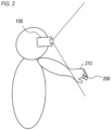
- FIG. 2 is a schematic diagram illustrating a state where a user has the HMD 100 worn and the controller 200 attached.
- the user has the HMD 100 worn on the head and the ring-shaped controller 200 attached to a hand 210.
- the controller 200 is shaped like a ring, enabling the user to freely move a hand with the controller 200 attached to a finger.
- the shape of the controller 200 is a ring, but it is not limited to this shape.
- the controller 200 may also be shaped like a glove that is attachable to a hand.
- the controller 200 may be designed to be holdable by or attachable to a user's hand for user convenience.
- an operation interface for operating the HMD 100 is the controller 200, but it is not limited to this.
- the operation interface may also be a user's hand or finger.
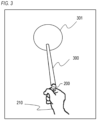
- FIG. 3 is a schematic diagram illustrating a display example of a ray.
- the ray is a beam-shaped display item (graphic) indicating a position pointed to by a user.
- a ray 300 is displayed toward CG 301 from the controller 200 attached to the hand 210 of a user.
- the tip-end position and angle of the ray 300 are determined on the basis of information related to the position and orientation of the controller 200 attached to the hand 210 of the user.
- the user is capable of operating items in virtual space such as the CG 301 using the ray 300.
- the ray 300 is displayed on the basis of both the position and orientation of the controller 200 in the first embodiment. However, the ray 300 may also be displayed on the basis of one of the position and orientation of the controller 200.
- FIG. 4 is a schematic diagram illustrating a state where another real object (here, a smartphone 400) is held by the hand 210 with the controller 200 attached.
- the ray 300 is displayed toward the CG 301 from the controller 200.
- a user may feel that the ray 300 is cumbersome.
- the functions of the controller 200 are disabled when a hand with the controller 200 attached is in contact with a specified real object.
- FIG. 5 is a flowchart illustrating disabling processing according to the first embodiment.
- the control unit 123 acquires a real image (an image of real space) captured by the imaging unit 111 through the image acquisition unit 121.
- step S502 the control unit 123 determines whether a hand with the controller 200 attached is in contact with a real object on the basis of the acquired real image.
- the processing proceeds to step S503 when the hand with the controller 200 attached is in contact with the real object. Otherwise, the processing proceeds to step S501.
- the control unit 123 may detect the region of the hand and the region of the real object from the real image, and determine whether the hand is in contact with the real object on the basis of the positional relationship between these regions.
- the control unit 123 may determine that the hand is in contact with the real object when the distance between the region of the hand and the region of the real object is less than a threshold, and determine that the hand is not in contact with the real object when the distance is at least the threshold.
- control unit 123 may determine that the hand is in contact with the real object when the region of the hand overlaps with the region of the real object, and determine that the hand is not in contact with the real object when the region of the hand does not overlap with the region of the real object. Note that in step S502, the region of the controller 200 is not determined as the region of the real object.
- the control unit 123 acquires information related to a specified real object from the ROM 130.
- the control unit 123 acquires, as the information related to the specified real object, a disabling image where the specified real object is reflected.
- the specified real object refers to a real object that disables the functions of the controller 200 when the hand with the controller 200 attached is in contact with the real obj ect.
- step S504 the control unit 123 determines whether the real object reflected in the real image matches the real object reflected in the disabling image. The processing proceeds to step S505 when the real object reflected in the real image matches the real object reflected in the disabling image. Otherwise, the processing proceeds to step S501.
- the functions of the controller 200 are not disabled when a real object in contact with a hand does not match a specified real object.
- the functions of the controller 200 may be disabled when the hand is in contact with a real object other than the controller 200.
- the functions of the controller 200 are enabled (the disabled state of the functions of the controller 200 is cancelled).
- the functions of the controller 200 are also enabled.
- FIG. 6 is a flowchart illustrating enabling processing according to the first embodiment.
- the control unit 123 acquires a real image captured by the imaging unit 111 through the image acquisition unit 121.
- step S602 the control unit 123 determines whether a hand with the controller 200 attached is reflected in the real image (whether the region of the hand is included in the real image). The processing proceeds to step S604 when the hand with the controller 200 attached is reflected in the real image. Otherwise, the processing proceeds to step S603.
- step S603 the control unit 123 enables the functions of the controller 200 that were disabled in step S505 of FIG. 5 .
- step S604 the control unit 123 determines whether the hand with the controller 200 attached is in contact with a real object on the basis of the acquired real image.
- a method for determining whether the hand is in contact with the real object may be the same as the method performed in step S502.
- the processing proceeds to step S601 when the hand is in contact with the real object.
- the processing proceeds to step S603, enabling the functions of the controller 200.
- step S505 of FIG. 5 the control unit 123 disables all the three functions, i.e., the function of displaying a ray, the function of receiving operations on the controller 200, and the function of vibrating the controller 200.
- the control unit 123 disables all the three functions, i.e., the function of displaying a ray, the function of receiving operations on the controller 200, and the function of vibrating the controller 200.
- any one of these functions may also be disabled, or two or three of these functions may also be disabled.
- functions associated with the controller 200 that are different from these functions may also be disabled.
- a real object detects a user operation and outputs information (detection result) indicating whether a user is operating the real object. Then, an HMD 100 determines whether to disable the functions of a controller 200 on the basis of the information output from the real object.
- the HMD 100 regards a state where the user is operating the real object as a state where a hand is in contact with the real object, and regards a state where the user is not operating the real object as a state where the hand is not in contact with the real object.
- a state where the user is operating the real object as a state where a hand is in contact with the real object
- a state where the user is not operating the real object as a state where the hand is not in contact with the real object.
- FIG. 7 is a sequence diagram illustrating disabling processing according to the second embodiment.
- a real object refers to an object operable by a user, such as a smartphone 400.
- the HMD 100 communicates with the smartphone 400 via a communication unit 150.
- step S701 the smartphone 400 detects a user operation on the smartphone 400 (determines whether a user operation has been performed). The smartphone 400 waits for the detection of the user operation. After the detection of the user operation, the processing proceeds to step S702.
- step S702 the smartphone 400 notifies (outputs) the HMD 100 of the detection of the user operation.
- a control unit 123 of the HMD 100 disables the functions of the controller 200 when receiving the notification (notification indicating that the smartphone 400 has detected the user operation) from the smartphone 400 via the communication unit 150.
- FIG. 8 is a flowchart illustrating disabling processing according to the third embodiment.
- a control unit 123 acquires a real image captured by an imaging unit 111 through an image acquisition unit 121.
- the control unit 123 determines whether a hand with the controller 200 attached is in contact with a real object on the basis of the acquired real image. The processing proceeds to step S803 when the hand with the controller 200 attached is in contact with the real object. Otherwise, the processing proceeds to S801.
- the functions of a controller 200 are enabled while a real object is in contact with CG in virtual space (three-dimensional space where the real world and the virtual world are merged).
- CG three-dimensional space where the real world and the virtual world are merged.
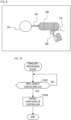
- FIG. 9 is a schematic diagram illustrating a state where a real object is in contact with CG in virtual space.
- a user holds a driver 900 serving as a real object by a hand 210 with the controller 200 attached.
- a tip-end tool 901 of the driver 900 is in contact with CG 301.
- the vibrating function of the controller 200 is disabled while the hand with the controller 200 attached is in contact with the driver 900.
- the hand with the controller 200 attached is in contact with the driver 900 and moving, the vibrating function of the controller 200 is disabled.
- the tip-end tool 901 (real object) of the driver 900 is in contact with the CG 301, it is possible to enable the vibrating function of the controller 200 regardless of whether the hand is in contact with the real object.
- a control unit 123 of an HMD 100 is enabled to transmit a vibrating instruction to the controller 200 to vibrate the same, and also enabled to notify the user of the contact between the tip-end tool 901 and the CG 301.
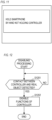
- FIG. 10 is a flowchart illustrating enabling processing according to the fourth embodiment.
- the control unit 123 determines whether a real object is in contact with CG. The processing proceeds to step S1002 when the real object is in contact with the CG. Otherwise, the processing proceeds to step S1001.
- the control unit 123 enables the functions of the controller 200 and ends the enabling processing.
- the tip-end tool 901 serves as a real object.
- the tip-end tool 901 may also be CG.
- the tip-end tool 901 (CG) may be overlaid onto the driver 900 (real object), and the controller 200 may be configured to vibrate when the tip-end tool 901 comes into contact with the CG 301.
- the functions of the controller 200 may be enabled.
- specified notification is performed when a hand with a controller 200 attached is in contact with a real object.
- a user is enabled to easily grasp a reason why the functions of the controller 200 are disabled.
- FIG. 11 is a schematic diagram illustrating an alert screen.
- the alert screen is a screen that, when a user holds another real object by a hand with the controller 200 attached, alerts (notifies) the user to hold the real object by a different hand.
- the control unit 123 displays the alert screen illustrated in FIG. 11 on a display unit 112 when determining in step S502 of FIG. 5 that the hand with the controller 200 attached is in contact with the real object. Note that notification may be performed not only by the display of the alert screen but also by, for example, the output of sound.
- notification is performed after the disabling of the controller 200 in the fifth embodiment, but the disabling may be omitted. Even with such a configuration, it is possible to prevent false operations of the controller 200. Further, it is possible to reduce processing loads with the omission of the disabling.
- the HMD 100 determines whether a hand is in contact with a real object on the basis of a real image.
- a controller 200 regards a state where the controller 200 is in contact with a real object as a state where a hand is in contact with the real object, and regards a state where the controller 200 is not in contact with the real object as a state where the hand is not in contact with the real object. In this manner, the controller 200 determines whether a hand is in contact with a real object.
- the real object refers to a real object other than the controller 200 (and a hand).
- FIG. 12 is a flowchart illustrating disabling processing according to the sixth embodiment.
- a CPU 201 of the controller 200 detects the contact between the controller 200 and a real object (determines whether the controller 200 is in contact with the real object) by a contact detection unit 206.
- the CPU 201 waits for the detection of the contact between the controller 200 and the real object.
- the processing proceeds to step S 1202 after the detection of the contact.
- the controller 200 may determine whether the controller 200 is in contact with a real object, and output information (determination result) indicating whether the controller 200 is in contact with the real object to the outside. Then, an HMD 100 may determine whether a hand is in contact with the real object on the basis of the information output from the controller 200, and switch between the enabling and disabling of the functions of the controller 200.
- control may be processing that is carried out by one piece of hardware (e.g., processor or circuit), or otherwise. Processing may be shared among a plurality of pieces of hardware (e.g., a plurality of processors, a plurality of circuits, or a combination of one or more processors and one or more circuits), thereby carrying out the control of the entire device.
- hardware e.g., processor or circuit
- Processing may be shared among a plurality of pieces of hardware (e.g., a plurality of processors, a plurality of circuits, or a combination of one or more processors and one or more circuits), thereby carrying out the control of the entire device.
- the above processor is a processor in the broad sense, and includes general-purpose processors and dedicated processors.
- general-purpose processors include a central processing unit (CPU), a micro processing unit (MPU), a digital signal processor (DSP), and so forth.
- dedicated processors include a graphics processing unit (GPU), an application-specific integrated circuit (ASIC), a programmable logic device (PLD), and so forth.
- PLDs include a field-programmable gate array (FPGA), a complex programmable logic device (CPLD), and so forth.
- Embodiment(s) of the present invention can also be realized by a computer of a system or apparatus that reads out and executes computer executable instructions (e.g., one or more programs) recorded on a storage medium (which may also be referred to more fully as a 'non-transitory computer-readable storage medium') to perform the functions of one or more of the above-described embodiment(s) and/or that includes one or more circuits (e.g., application specific integrated circuit (ASIC)) for performing the functions of one or more of the above-described embodiment(s), and by a method performed by the computer of the system or apparatus by, for example, reading out and executing the computer executable instructions from the storage medium to perform the functions of one or more of the above-described embodiment(s) and/or controlling the one or more circuits to perform the functions of one or more of the above-described embodiment(s).
- computer executable instructions e.g., one or more programs
- a storage medium which may also be referred to more fully as
- the computer may comprise one or more processors (e.g., central processing unit (CPU), micro processing unit (MPU)) and may include a network of separate computers or separate processors to read out and execute the computer executable instructions.
- the computer executable instructions may be provided to the computer, for example, from a network or the storage medium.
- the storage medium may include, for example, one or more of a hard disk, a random-access memory (RAM), a read only memory (ROM), a storage of distributed computing systems, an optical disk (such as a compact disc (CD), digital versatile disc (DVD), or Blu-ray Disc (BD) TM ), a flash memory device, a memory card, and the like.
Landscapes
- Engineering & Computer Science (AREA)
- General Engineering & Computer Science (AREA)
- Theoretical Computer Science (AREA)
- Human Computer Interaction (AREA)
- Physics & Mathematics (AREA)
- General Physics & Mathematics (AREA)
- User Interface Of Digital Computer (AREA)
Abstract
An information processing device according to the present invention is an information processing device configured to receive an operation by a user on an operation interface, and includes: acquisition means configured to acquire first information related to contact between a real object and a hand of the user, the real object being different from the operation interface and the information processing device; and control means configured to disable a function associated with the operation interface in a case where the first information acquired by the acquisition means indicates that the hand is in contact with the real object.
Description
- The present invention relates to an information processing device, a control method of an information processing device, a program, and a computer readable medium.
- In cross-reality (XR) systems that enable users to experience virtual realities, head-mounted displays (HMDs) are often used. Further, controllers may be used to convert the motions of users' hands into motions in virtual space (virtual reality space). The HMDs represent glasses-shaped devices including small displays worn on users' heads.
-
Japanese Patent Application Laid-Open Publication No. 2015-152973 Japanese Patent Application Laid-Open Publication No. 2021-8794 - However, in the technology disclosed in
Japanese Patent Application Laid-Open Publication No. 2015-152973 Japanese Patent Application Laid-Open Publication No. 2021-8794 Japanese Patent Application Laid-Open Publication No. 2015-152973 Japanese Patent Application Laid-Open Publication No. 2021-8794 - The present invention provides a technology capable of preventing false operations of controllers with high accuracy.
- The present invention in its first aspect provides an information processing device as specified in claims 1 to 12.
- The present invention in its second aspect provides a control method of an information processing device as specified in claim 13.
- The present invention in its third aspect provides a program as specified in claim 14. The present invention in its fourth aspect provides a computer readable medium as specified in claim 15.
- Further features of the present invention will become apparent from the following description of embodiments with reference to the attached drawings.
-
-
FIG. 1 is a block diagram illustrating the configuration of an information processing system according to a first embodiment; -
FIG. 2 is a schematic diagram illustrating a state where a user has an HMD worn and a controller attached; -
FIG. 3 is a schematic diagram illustrating a display example of a ray; -
FIG. 4 is a schematic diagram illustrating a state where another real object is held by a hand with the controller attached; -
FIG. 5 is a flowchart illustrating disabling processing according to the first embodiment; -
FIG. 6 is a flowchart illustrating enabling processing according to the first embodiment; -
FIG. 7 is a sequence diagram illustrating disabling processing according to a second embodiment; -
FIG. 8 is a flowchart illustrating disabling processing according to a third embodiment; -
FIG. 9 is a schematic diagram illustrating a state where a real object is in contact with CG; -
FIG. 10 is a flowchart illustrating enabling processing according to a fourth embodiment; -
FIG. 11 is a schematic diagram illustrating an alert screen according to a fifth embodiment; and -
FIG. 12 is a flowchart illustrating disabling processing according to a sixth embodiment. - Hereinafter, embodiments of the present invention will be described in detail on the basis of the accompanying drawings. Note that the following embodiments are provided as an example of means for implementing the present invention, and may be appropriately modified or changed depending on the configurations or various conditions of devices to which the present invention is applied. Further, it is also possible to appropriately combine the respective embodiments together.
-
FIG. 1 is a block diagram illustrating the configuration of an information processing system according to a first embodiment. The information processing system includes a Head-Mounted Display (HMD) 100, which is an example of an information processing device, and acontroller 200. - The HMD 100 includes a
display device 101 and acontrol device 102. - The
display device 101 includes animaging unit 111, adisplay unit 112, and a position-and-orientation detection unit 113. Thedisplay device 101 constitutes, for example, the glasses-shaped display portion of the HMD 100. Thedisplay device 101 displays a composite image where an image of real space representing a user's field of vision (an image obtained by capturing the front range of the HMD 100) is combined with a computer graphic (CG), which is a virtual object in a form corresponding to a user's position and orientation. Thus, a user wearing the HMD 100 is capable of experiencing various virtual realities (mixed realities), such as those where CG are merged with real space. Note that thedisplay device 101 may also have two display units, one for the right eye and the other for the left eye, to generate stereo images. In the following description, it is assumed that thedisplay device 101 constitutes the display portion of theHMD 100. However, the display portion may include a tablet terminal or another display device. That is, any display device, which is transportable and capable of displaying an image corresponding to a user's field of vision, is available as thedisplay device 101. - The
imaging unit 111 is composed of an objective optical system that takes in external light (light of real space), an image sensor that converts light signals into electric signals, and the like. Theimaging unit 111 captures an image representing a user's field of vision (an image of real space). - The
display unit 112 displays an image generated by thecontrol device 102. - The position-and-
orientation detection unit 113 detects a user's position and orientation in real space. For example, a position-and-orientation sensor using an acceleration sensor and an angular speed sensor, a direction sensor using terrestrial magnetism, and an orientation sensor using a GPS are available as the position-and-orientation detection unit 113. - The
control device 102 includes aCPU 120, aROM 130, aRAM 140, and acommunication unit 150. As thecontrol device 102, a device having a high-performance computation processing function or a graphic display function is assumed to be used. The connection between thecontrol device 102 and thedisplay device 101 enables a user wearing the HMD 100 to view video of virtual space. The video of virtual space may also include video of a mixed-reality world where the real world and the virtual world are merged in real time and seamlessly. - An
image acquisition unit 121, a position-and-orientation acquisition unit 122, and acontrol unit 123 are control blocks that operate inside theCPU 120. - The
image acquisition unit 121 acquires an image of real space captured by theimaging unit 111 of thedisplay device 101. - The position-and-
orientation acquisition unit 122 acquires information indicating a user's position and orientation detected by the position-and-orientation detection unit 113 of thedisplay device 101. The position-and-orientation acquisition unit 122 may also detect a marker arranged in real space from an image of the real space acquired by theimage acquisition unit 121 to acquire the information indicating the position and orientation. - The
control unit 123 generates a composite image by combining an image of real space acquired by theimage acquisition unit 121 with CG, and transmits the generated composite image to thedisplay unit 112 of thedisplay device 101. Further, thecontrol unit 123 acquires information output from thecontroller 200 via thecommunication unit 150, and controls thedisplay device 101 on the basis of the acquired information. - The
ROM 130 is a storage unit that stores information such as CG. Note that thecontrol unit 123 is capable of switching CG read from the ROM 130 (that is, CG used to generate a composite image). - The
RAM 140 is a work memory. In theRAM 140, constants for operating thecontrol unit 123, variables, programs read from theROM 130, or the like are stored. - The
communication unit 150 is an interface for connecting with external devices. Thecommunication unit 150 includes an interface for communicating with external devices through a so-called wireless LAN that complies with the IEEE802.11 standard. Further, thecommunication unit 150 includes an interface for communicating with external devices through so-called Bluetooth (Registered Trademark) that complies with the IEEE802.15.1 standard. Note that the communication system is not limited to a wireless LAN or Bluetooth (Registered Trademark). A wired or wireless communication system may be used as long as it is capable of performing communication, and any type of communication protocol may be used. TheHMD 100 communicates with thecontroller 200 via thecommunication unit 150. Further, thecommunication unit 150 is capable of communicating with equipment other than thecontroller 200 such as smartphones. - The
display device 101 and thecontrol device 102 are connected to enable data communication with each other. Accordingly, thedisplay device 101 and thecontrol device 102 may be connected to each other in a wired or wireless fashion. Note that thedisplay device 101 and thecontrol device 102 may be separate devices or integrated into a single unit so as to be capable of being carried by a user. Further, some of the processing performed by thedisplay device 101, thecontrol device 102, and thecontroller 200 may be implemented by external equipment (such as smartphones, personal computers, workstations, video-game consoles, and server devices in the cloud). - The
controller 200 includes aCPU 201, amotion detection unit 202, anoperation unit 203, avibration unit 204, acommunication unit 205, and acontact detection unit 206. Thecontroller 200 is a device for operating theHMD 100. TheCPU 201 controls the respective units of thecontroller 200. - The
motion detection unit 202 has an Inertial Measurement Unit (IMU; an inertial sensor) capable of detecting inertial information (the spatial motion amount or angle) of thecontroller 200. Note that themotion detection unit 202 may also have any device as long as the device does not hinder the miniaturization of thecontroller 200 and is capable of detecting inertial information (information such as differences in position, speed, and acceleration). - The
operation unit 203 may include any of a button, a touch pad, a touch panel, a directional cross-key, a joystick, a trackpad device, and the like. For example, a user is enabled to display a menu including a pointer on thedisplay device 101 by pressing and holding the button. After that, the user is enabled to move the pointer to a desired item by pressing the directional cross-key in any direction. Then, the user is enabled to perform a determination action to determine the selection of the item by pressing the button. For example, the user is enabled to switch between displaying and hiding of aray 300 illustrated inFIG. 3 . User operation information to theoperation unit 203 is transmitted to theHMD 100 via thecommunication unit 205. - The
vibration unit 204 causes thecontroller 200 to vibrate. For example, when theray 300 illustrated inFIG. 3 comes into contact withCG 301, theCPU 201 receives a vibration instruction from theHMD 100 via thecommunication unit 205. In response to the vibration instruction, theCPU 201 controls thevibration unit 204 to vibrate thecontroller 200. Through the vibration of thecontroller 200, the user is enabled to recognize that theray 300 has come into contact with theCG 301. - The
communication unit 205 is an interface for connecting with external devices. Thecontroller 200 communicates with theHMD 100 via thecommunication unit 205. Thecommunication unit 205 has the same configuration as that of, for example, thecommunication unit 150. - The
contact detection unit 206 is a function unit for detecting whether thecontroller 200 has come into contact with a real object. Thecontact detection unit 206 detects whether thecontroller 200 has come into contact with a real object, using, for example, a pressure sensor or a contact sensor. -
FIG. 2 is a schematic diagram illustrating a state where a user has theHMD 100 worn and thecontroller 200 attached. As illustrated inFIG. 2 , the user has theHMD 100 worn on the head and the ring-shapedcontroller 200 attached to ahand 210. Thecontroller 200 is shaped like a ring, enabling the user to freely move a hand with thecontroller 200 attached to a finger. Note that the shape of thecontroller 200 is a ring, but it is not limited to this shape. For example, thecontroller 200 may also be shaped like a glove that is attachable to a hand. As described above, thecontroller 200 may be designed to be holdable by or attachable to a user's hand for user convenience. Further, in the first embodiment, an operation interface for operating theHMD 100 is thecontroller 200, but it is not limited to this. The operation interface may also be a user's hand or finger. -
FIG. 3 is a schematic diagram illustrating a display example of a ray. The ray is a beam-shaped display item (graphic) indicating a position pointed to by a user. As illustrated inFIG. 3 , aray 300 is displayed towardCG 301 from thecontroller 200 attached to thehand 210 of a user. The tip-end position and angle of theray 300 are determined on the basis of information related to the position and orientation of thecontroller 200 attached to thehand 210 of the user. The user is capable of operating items in virtual space such as theCG 301 using theray 300. Note that theray 300 is displayed on the basis of both the position and orientation of thecontroller 200 in the first embodiment. However, theray 300 may also be displayed on the basis of one of the position and orientation of thecontroller 200. -
FIG. 4 is a schematic diagram illustrating a state where another real object (here, a smartphone 400) is held by thehand 210 with thecontroller 200 attached. LikeFIG. 3 , theray 300 is displayed toward theCG 301 from thecontroller 200. However, when theray 300 is displayed while thesmartphone 400 is held by thehand 210, a user may feel that theray 300 is cumbersome. Further, when the user operates thesmartphone 400 or when the user only wants to contact thesmartphone 400, false operations of thecontroller 200 may occur. Therefore, in the first embodiment, the functions of thecontroller 200 are disabled when a hand with thecontroller 200 attached is in contact with a specified real object. -
FIG. 5 is a flowchart illustrating disabling processing according to the first embodiment. In step S501, thecontrol unit 123 acquires a real image (an image of real space) captured by theimaging unit 111 through theimage acquisition unit 121. - In step S502, the
control unit 123 determines whether a hand with thecontroller 200 attached is in contact with a real object on the basis of the acquired real image. The processing proceeds to step S503 when the hand with thecontroller 200 attached is in contact with the real object. Otherwise, the processing proceeds to step S501. For example, thecontrol unit 123 may detect the region of the hand and the region of the real object from the real image, and determine whether the hand is in contact with the real object on the basis of the positional relationship between these regions. Thecontrol unit 123 may determine that the hand is in contact with the real object when the distance between the region of the hand and the region of the real object is less than a threshold, and determine that the hand is not in contact with the real object when the distance is at least the threshold. Further, thecontrol unit 123 may determine that the hand is in contact with the real object when the region of the hand overlaps with the region of the real object, and determine that the hand is not in contact with the real object when the region of the hand does not overlap with the region of the real object. Note that in step S502, the region of thecontroller 200 is not determined as the region of the real object. - In the
ROM 130, information related to a specified real object is stored. In step S503, thecontrol unit 123 acquires information related to a specified real object from theROM 130. In the first embodiment, thecontrol unit 123 acquires, as the information related to the specified real object, a disabling image where the specified real object is reflected. The specified real object refers to a real object that disables the functions of thecontroller 200 when the hand with thecontroller 200 attached is in contact with the real obj ect. - In step S504, the
control unit 123 determines whether the real object reflected in the real image matches the real object reflected in the disabling image. The processing proceeds to step S505 when the real object reflected in the real image matches the real object reflected in the disabling image. Otherwise, the processing proceeds to step S501. - In step S505, the
control unit 123 disables the functions of thecontroller 200 and ends the disabling processing. The disabled functions include, for example, the function of displaying a ray, the function of receiving operations on thecontroller 200, and the function of vibrating thecontroller 200. - In the first embodiment, the specified real object refers to a smartphone. The
control unit 123 determines whether the real object in contact with the hand matches the smartphone on the basis of the real image captured by theimaging unit 111 and an image of the smartphone stored in theROM 130. When the hand is in contact with the smartphone, the functions of thecontroller 200 are disabled. Thus, when thesmartphone 400 is held by thehand 210 with thecontroller 200 attached as illustrated inFIG. 4 , it is possible to prevent the user from feeling obstructed by that theray 300 or making false operations with thecontroller 200 with high accuracy. Note that the specified real object is not limited to smartphones but may also include objects operated by the user such as tablets, keyboards, mice, car steering wheels, and drivers, as well as objects not operated by the user such as mugs. Further, the specified real object is not limited to one type but may also include a plurality of types of real objects. - Further, in the first embodiment, the functions of the
controller 200 are not disabled when a real object in contact with a hand does not match a specified real object. However, the functions of thecontroller 200 may be disabled when the hand is in contact with a real object other than thecontroller 200. - When a hand with the
controller 200 attached separates from a real object, the functions of thecontroller 200 are enabled (the disabled state of the functions of thecontroller 200 is cancelled). In addition, when the position of a hand with thecontroller 200 attached is outside the imaging range of theimaging unit 111, making it impossible to determine whether the hand is in contact with a real object, the functions of thecontroller 200 are also enabled. -
FIG. 6 is a flowchart illustrating enabling processing according to the first embodiment. In step S601, thecontrol unit 123 acquires a real image captured by theimaging unit 111 through theimage acquisition unit 121. - In step S602, the
control unit 123 determines whether a hand with thecontroller 200 attached is reflected in the real image (whether the region of the hand is included in the real image). The processing proceeds to step S604 when the hand with thecontroller 200 attached is reflected in the real image. Otherwise, the processing proceeds to step S603. - In step S603, the
control unit 123 enables the functions of thecontroller 200 that were disabled in step S505 ofFIG. 5 . - In step S604, the
control unit 123 determines whether the hand with thecontroller 200 attached is in contact with a real object on the basis of the acquired real image. A method for determining whether the hand is in contact with the real object may be the same as the method performed in step S502. The processing proceeds to step S601 when the hand is in contact with the real object. When the hand is not in contact with the real object (the hand separates from the real object), the processing proceeds to step S603, enabling the functions of thecontroller 200. - As described above, when a hand with the
controller 200 attached separates from a smartphone after coming into contact with the smartphone or when the hand is not reflected in a real image, the functions of thecontroller 200 that were once disabled are enabled. Thus, a user is enabled to resume various operations using thecontroller 200. - In step S505 of
FIG. 5 , thecontrol unit 123 disables all the three functions, i.e., the function of displaying a ray, the function of receiving operations on thecontroller 200, and the function of vibrating thecontroller 200. However, any one of these functions may also be disabled, or two or three of these functions may also be disabled. Further, functions associated with thecontroller 200 that are different from these functions may also be disabled. - In the first embodiment, a determination is made as to whether a hand with the
controller 200 attached is in contact with a real object on the basis of a real image captured by theimaging unit 111, thereby acquiring information (determination result) indicating whether the hand is in contact with the real object. Then, a determination is made as to whether to disable the functions of thecontroller 200 on the basis of the acquired determination result and information (disabling image) related to a specified real object stored in theROM 130. In a second embodiment, a real object detects a user operation and outputs information (detection result) indicating whether a user is operating the real object. Then, anHMD 100 determines whether to disable the functions of acontroller 200 on the basis of the information output from the real object. TheHMD 100 regards a state where the user is operating the real object as a state where a hand is in contact with the real object, and regards a state where the user is not operating the real object as a state where the hand is not in contact with the real object. Thus, even if information related to a specified real object is not stored in aROM 130, it is possible to suitably determine whether to disable the functions of thecontroller 200. -
FIG. 7 is a sequence diagram illustrating disabling processing according to the second embodiment. In the second embodiment, a real object refers to an object operable by a user, such as asmartphone 400. TheHMD 100 communicates with thesmartphone 400 via acommunication unit 150. - In step S701, the
smartphone 400 detects a user operation on the smartphone 400 (determines whether a user operation has been performed). Thesmartphone 400 waits for the detection of the user operation. After the detection of the user operation, the processing proceeds to step S702. - In step S702, the
smartphone 400 notifies (outputs) theHMD 100 of the detection of the user operation. - In step S703, a
control unit 123 of theHMD 100 disables the functions of thecontroller 200 when receiving the notification (notification indicating that thesmartphone 400 has detected the user operation) from thesmartphone 400 via thecommunication unit 150. - In the second embodiment, a real object determines whether a user is operating the real object. In a third embodiment, an
HMD 100 acquires information indicating whether a hand with acontroller 200 attached is in contact with a real object and information related to the motion of the hand, and determines whether to disable the functions of thecontroller 200 on the basis of these acquired information. Thus, even if a real object does not have the function of determining whether a user is operating the real object, it is possible to suitably determine whether to disable the functions of thecontroller 200. -
FIG. 8 is a flowchart illustrating disabling processing according to the third embodiment. In step S801, acontrol unit 123 acquires a real image captured by animaging unit 111 through animage acquisition unit 121. In step S802, thecontrol unit 123 determines whether a hand with thecontroller 200 attached is in contact with a real object on the basis of the acquired real image. The processing proceeds to step S803 when the hand with thecontroller 200 attached is in contact with the real object. Otherwise, the processing proceeds to S801. - In step S803, the
control unit 123 determines whether the motion amount of the hand in contact with the real object is at least a specified threshold. The processing proceeds to S804 when the motion amount of the hand in contact with the real object is at least the specified threshold. Otherwise, the processing proceeds to step S801. The specified threshold may be, for example, a motion amount that enables determination of whether the real object is being operated (whether the hand is moving), such as a representative motion amount (a mean, a minimum value, or a middle value) observed when the real object is being operated. - In step S804, the
control unit 123 disables the functions of thecontroller 200 and ends the disabling processing. - In a fourth embodiment, the functions of a
controller 200 are enabled while a real object is in contact with CG in virtual space (three-dimensional space where the real world and the virtual world are merged). Thus, it is possible to prevent a decrease in convenience due to the disabling of the functions of thecontroller 200, such as a case where it becomes difficult to determine whether a real object is in contact with CG, for example, when thecontroller 200 stops vibrating. -
FIG. 9 is a schematic diagram illustrating a state where a real object is in contact with CG in virtual space. A user holds adriver 900 serving as a real object by ahand 210 with thecontroller 200 attached. A tip-end tool 901 of thedriver 900 is in contact withCG 301. - In the first embodiment, when it is assumed that the
driver 900 serves as a specified real object, the vibrating function of thecontroller 200 is disabled while the hand with thecontroller 200 attached is in contact with thedriver 900. Further, in the third embodiment, when the hand with thecontroller 200 attached is in contact with thedriver 900 and moving, the vibrating function of thecontroller 200 is disabled. Conversely, in the fourth embodiment, when the tip-end tool 901 (real object) of thedriver 900 is in contact with theCG 301, it is possible to enable the vibrating function of thecontroller 200 regardless of whether the hand is in contact with the real object. As a result, acontrol unit 123 of anHMD 100 is enabled to transmit a vibrating instruction to thecontroller 200 to vibrate the same, and also enabled to notify the user of the contact between the tip-end tool 901 and theCG 301. -
FIG. 10 is a flowchart illustrating enabling processing according to the fourth embodiment. In step S1001, thecontrol unit 123 determines whether a real object is in contact with CG. The processing proceeds to step S1002 when the real object is in contact with the CG. Otherwise, the processing proceeds to step S1001. In step S1002, thecontrol unit 123 enables the functions of thecontroller 200 and ends the enabling processing. - Note that an example was described where the tip-
end tool 901 serves as a real object. However, the tip-end tool 901 may also be CG. In this case, the tip-end tool 901 (CG) may be overlaid onto the driver 900 (real object), and thecontroller 200 may be configured to vibrate when the tip-end tool 901 comes into contact with theCG 301. As described above, when CG overlaid onto a real object held by a user is in contact with different CG, the functions of thecontroller 200 may be enabled. - In a fifth embodiment, specified notification is performed when a hand with a
controller 200 attached is in contact with a real object. Thus, a user is enabled to easily grasp a reason why the functions of thecontroller 200 are disabled. -
FIG. 11 is a schematic diagram illustrating an alert screen. The alert screen is a screen that, when a user holds another real object by a hand with thecontroller 200 attached, alerts (notifies) the user to hold the real object by a different hand. Thecontrol unit 123 displays the alert screen illustrated inFIG. 11 on adisplay unit 112 when determining in step S502 ofFIG. 5 that the hand with thecontroller 200 attached is in contact with the real object. Note that notification may be performed not only by the display of the alert screen but also by, for example, the output of sound. - Note that notification is performed after the disabling of the
controller 200 in the fifth embodiment, but the disabling may be omitted. Even with such a configuration, it is possible to prevent false operations of thecontroller 200. Further, it is possible to reduce processing loads with the omission of the disabling. - In the first embodiment, the
HMD 100 determines whether a hand is in contact with a real object on the basis of a real image. In a sixth embodiment, acontroller 200 regards a state where thecontroller 200 is in contact with a real object as a state where a hand is in contact with the real object, and regards a state where thecontroller 200 is not in contact with the real object as a state where the hand is not in contact with the real object. In this manner, thecontroller 200 determines whether a hand is in contact with a real object. Thus, for example, even when a real image is not acquired, it is possible to determine whether to disable the functions of thecontroller 200. Note that in the sixth embodiment, the real object refers to a real object other than the controller 200 (and a hand). -
FIG. 12 is a flowchart illustrating disabling processing according to the sixth embodiment. In step S1201, aCPU 201 of thecontroller 200 detects the contact between thecontroller 200 and a real object (determines whether thecontroller 200 is in contact with the real object) by acontact detection unit 206. TheCPU 201 waits for the detection of the contact between thecontroller 200 and the real object. The processing proceeds to step S 1202 after the detection of the contact. - In step S1202, the
CPU 201 disables the functions of thecontroller 200 and ends the disabling processing. - Note that the
controller 200 may determine whether thecontroller 200 is in contact with a real object, and output information (determination result) indicating whether thecontroller 200 is in contact with the real object to the outside. Then, anHMD 100 may determine whether a hand is in contact with the real object on the basis of the information output from thecontroller 200, and switch between the enabling and disabling of the functions of thecontroller 200. - Note that the above-described various types of control may be processing that is carried out by one piece of hardware (e.g., processor or circuit), or otherwise. Processing may be shared among a plurality of pieces of hardware (e.g., a plurality of processors, a plurality of circuits, or a combination of one or more processors and one or more circuits), thereby carrying out the control of the entire device.
- Also, the above processor is a processor in the broad sense, and includes general-purpose processors and dedicated processors. Examples of general-purpose processors include a central processing unit (CPU), a micro processing unit (MPU), a digital signal processor (DSP), and so forth. Examples of dedicated processors include a graphics processing unit (GPU), an application-specific integrated circuit (ASIC), a programmable logic device (PLD), and so forth. Examples of PLDs include a field-programmable gate array (FPGA), a complex programmable logic device (CPLD), and so forth.
- The embodiment described above (including variation examples) is merely an example. Any configurations obtained by suitably modifying or changing some configurations of the embodiment within the scope of the subject matter of the present invention are also included in the present invention. The present invention also includes other configurations obtained by suitably combining various features of the embodiment.
- According to the present invention, it is possible to prevent false operations of controllers with high accuracy.
- Embodiment(s) of the present invention can also be realized by a computer of a system or apparatus that reads out and executes computer executable instructions (e.g., one or more programs) recorded on a storage medium (which may also be referred to more fully as a 'non-transitory computer-readable storage medium') to perform the functions of one or more of the above-described embodiment(s) and/or that includes one or more circuits (e.g., application specific integrated circuit (ASIC)) for performing the functions of one or more of the above-described embodiment(s), and by a method performed by the computer of the system or apparatus by, for example, reading out and executing the computer executable instructions from the storage medium to perform the functions of one or more of the above-described embodiment(s) and/or controlling the one or more circuits to perform the functions of one or more of the above-described embodiment(s). The computer may comprise one or more processors (e.g., central processing unit (CPU), micro processing unit (MPU)) and may include a network of separate computers or separate processors to read out and execute the computer executable instructions. The computer executable instructions may be provided to the computer, for example, from a network or the storage medium. The storage medium may include, for example, one or more of a hard disk, a random-access memory (RAM), a read only memory (ROM), a storage of distributed computing systems, an optical disk (such as a compact disc (CD), digital versatile disc (DVD), or Blu-ray Disc (BD)™), a flash memory device, a memory card, and the like.
- While the present invention has been described with reference to embodiments, it is to be understood that the invention is not limited to the disclosed embodiments, but is defined by the scope of the following claims.
Claims (15)
- An information processing device (100) configured to receive an operation by a user on an operation interface (200), the information processing device (100) comprising:acquisition means (123) configured to acquire first information related to contact between a real object (400, 900, 901) and a hand (210) of the user, the real object (400, 900, 901) being different from the operation interface (200) and the information processing device (100); andcontrol means (123) configured to disable a function associated with the operation interface (200) in a case where the first information acquired by the acquisition means (123) indicates that the hand (210) is in contact with the real object (400, 900, 901).
- The information processing device (100) according to claim 1, wherein
the control means (123) is configured not to disable the function in a case where the real object (400, 900, 901) in contact with the hand (210) does not match a specified real object (400, 900, 901). - The information processing device (100) according to claim 2, further comprising:storage means (140) configured to store second information related to the specified real object (400, 900, 901), whereinthe control means (123) is configured to determine whether the real object (400, 900, 901) in contact with the hand (210) matches the specified real object (400, 900, 901) based on the first information and the second information.
- The information processing device (100) according to any one of claims 1 to 3, wherein
the control means (123) is configured to enable the function in a case where the hand (210) separates from the real object (400, 900, 901) after coming into contact with the real object (400, 900, 901). - The information processing device (100) according to any one of claims 1 to 4, whereinthe real object (400, 900, 901) is an object operable by the user,the acquisition means (123) is configured to acquire, as the first information, information related to whether the user is operating the real object (400, 900, 901) from the real object (400, 900, 901), andthe first information is configured to indicate that the hand (210) is in contact with the real object (400, 900, 901) in a case where the user is operating the real object (400, 900, 901) and indicate that the hand (210) is not in contact with the real object (400, 900, 901) in a case where the user is not operating the real object (400, 900, 901).
- The information processing device (100) according to any one of claims 1 to 4, whereinthe acquisition means (123) is configured to acquire, as the first information, information related to whether the operation interface (200) is in contact with the real object (400, 900, 901) from the operation interface (200), andthe first information is configured to indicate that the hand (210) is in contact with the real object (400, 900, 901) in a case where the operation interface (200) is in contact with the real object (400, 900, 901) and indicate that the hand (210) is not in contact with the real object (400, 900, 901) in a case where the operation interface (200) is not in contact with the real object (400, 900, 901).
- The information processing device (100) according to any one of claims 1 to 4, whereinthe acquisition means (123) is configured to acquire the first information based on an image representing a field of vision of the user, andthe control means (123) is configured not to disable the function in a case where a region of the hand (210) is not included in the image.
- The information processing device (100) according to any one of claims 1 to 7, whereinthe acquisition means (123) is further configured to acquire third information related to motion of the hand (210), andthe control means (123) is configured, based on the first information and the third information, not to disable the function in a case where the hand (210) in contact with the real object (400, 900, 901) is not moving.
- The information processing device (100) according to any one of claims 1 to 8, wherein,
in a case where the real object (400, 900, 901) is in contact with a virtual object (301) in three-dimensional space where a real world and a virtual world are merged, the control means (123) is configured to enable the function regardless of whether the hand (210) is in contact with the real object (400, 900, 901). - The information processing device (100) according to any one of claims 1 to 9, wherein
the function associated with the operation interface (200) includes at least one of a function of displaying a graphic (300) based on a position or an orientation of the operation interface (200), a function of receiving an operation on the operation interface (200), and a function of vibrating the operation interface (200). - The information processing device (100) according to any one of claims 1 to 10, wherein
the control means (123) is further configured to perform specified notification in a case where the hand (210) is in contact with the real object (400, 900, 901). - The information processing device (100) according to any one of claims 1 to 11, wherein
the information processing device (100) is accommodated in a display device or the operation interface (200). - A control method of an information processing device (100) that receives an operation by a user on an operation interface (200), the control method comprising:acquiring (S502, S604, S802) first information related to contact between a real object (400, 900, 901) and a hand (210) of the user, the real object (400, 900, 901) being different from the operation interface (200) and the information processing device (100); anddisabling (S505, S703, S804, S1202) a function associated with the operation interface (200) in a case where the acquired first information indicates that the hand (210) is in contact with the real object (400, 900, 901).
- A computer program comprising instructions which, when the program is executed by a computer, cause the computer to carry out the method of claim 13.
- A computer readable medium having stored thereon the computer program of claim 14.
Applications Claiming Priority (1)
| Application Number | Priority Date | Filing Date | Title |
|---|---|---|---|
| JP2023174232A JP2025064452A (en) | 2023-10-06 | 2023-10-06 | Information processing device, information processing method, and program |
Publications (1)
| Publication Number | Publication Date |
|---|---|
| EP4535132A1 true EP4535132A1 (en) | 2025-04-09 |
Family
ID=93013727
Family Applications (1)
| Application Number | Title | Priority Date | Filing Date |
|---|---|---|---|
| EP24204668.8A Pending EP4535132A1 (en) | 2023-10-06 | 2024-10-04 | Information processing device, control method of information processing device, program, and computer readable medium |
Country Status (4)
| Country | Link |
|---|---|
| US (1) | US20250117084A1 (en) |
| EP (1) | EP4535132A1 (en) |
| JP (1) | JP2025064452A (en) |
| CN (1) | CN119784977A (en) |
Citations (5)
| Publication number | Priority date | Publication date | Assignee | Title |
|---|---|---|---|---|
| JP2015152973A (en) | 2014-02-10 | 2015-08-24 | レノボ・シンガポール・プライベート・リミテッド | Input device, input method, and computer-executable program |
| US20180095542A1 (en) * | 2016-09-30 | 2018-04-05 | Sony Interactive Entertainment Inc. | Object Holder for Virtual Reality Interaction |
| JP2021008794A (en) | 2019-07-03 | 2021-01-28 | 三井金属アクト株式会社 | Door open / close control system |
| US20230244313A1 (en) * | 2020-07-30 | 2023-08-03 | Sony Group Corporation | Information processing apparatus, tactile sense providing system, and program |
| US20230244316A1 (en) * | 2022-02-01 | 2023-08-03 | Microsoft Technology Licensing, Llc | Gesture recognition based on likelihood of interaction |
Family Cites Families (6)
| Publication number | Priority date | Publication date | Assignee | Title |
|---|---|---|---|---|
| US10055018B2 (en) * | 2014-08-22 | 2018-08-21 | Sony Interactive Entertainment Inc. | Glove interface object with thumb-index controller |
| US9746921B2 (en) * | 2014-12-31 | 2017-08-29 | Sony Interactive Entertainment Inc. | Signal generation and detector systems and methods for determining positions of fingers of a user |
| CN107210917A (en) * | 2015-02-20 | 2017-09-26 | 惠普发展公司有限责任合伙企业 | User authentication device |
| CN114072750A (en) * | 2019-07-09 | 2022-02-18 | 麦克赛尔株式会社 | Head-mounted display system, head-mounted display used by head-mounted display system and operation method of head-mounted display |
| US11949673B1 (en) * | 2019-07-23 | 2024-04-02 | BlueOwl, LLC | Gesture authentication using a smart ring |
| WO2022230264A1 (en) * | 2021-04-26 | 2022-11-03 | ソニーグループ株式会社 | Information processing device, information processing method, and program |
-
2023
- 2023-10-06 JP JP2023174232A patent/JP2025064452A/en active Pending
-
2024
- 2024-09-29 CN CN202411368892.0A patent/CN119784977A/en active Pending
- 2024-10-04 EP EP24204668.8A patent/EP4535132A1/en active Pending
- 2024-10-04 US US18/907,236 patent/US20250117084A1/en active Pending
Patent Citations (5)
| Publication number | Priority date | Publication date | Assignee | Title |
|---|---|---|---|---|
| JP2015152973A (en) | 2014-02-10 | 2015-08-24 | レノボ・シンガポール・プライベート・リミテッド | Input device, input method, and computer-executable program |
| US20180095542A1 (en) * | 2016-09-30 | 2018-04-05 | Sony Interactive Entertainment Inc. | Object Holder for Virtual Reality Interaction |
| JP2021008794A (en) | 2019-07-03 | 2021-01-28 | 三井金属アクト株式会社 | Door open / close control system |
| US20230244313A1 (en) * | 2020-07-30 | 2023-08-03 | Sony Group Corporation | Information processing apparatus, tactile sense providing system, and program |
| US20230244316A1 (en) * | 2022-02-01 | 2023-08-03 | Microsoft Technology Licensing, Llc | Gesture recognition based on likelihood of interaction |
Also Published As
| Publication number | Publication date |
|---|---|
| JP2025064452A (en) | 2025-04-17 |
| CN119784977A (en) | 2025-04-08 |
| US20250117084A1 (en) | 2025-04-10 |
Similar Documents
| Publication | Publication Date | Title |
|---|---|---|
| CN113826058A (en) | Artificial reality system with self-tactile virtual keyboard | |
| EP3389020A1 (en) | Information processing device, information processing method, and program | |
| EP2975492A1 (en) | Three-dimensional user interface device and three-dimensional operation processing method | |
| US11500476B1 (en) | Dual-transceiver based input devices | |
| CN113785262A (en) | Artificial reality system with finger-mapping self-tactile input method | |
| US20230083677A1 (en) | Information processing apparatus, information processing method, and storage medium | |
| EP3196734A1 (en) | Control device, control method, and program | |
| US12197652B2 (en) | Control device and control method with set priorities for input operations in competitive relationship | |
| US12416973B2 (en) | Information processing apparatus and information processing method | |
| EP3299930A1 (en) | Virtual reality interaction | |
| US20250117084A1 (en) | Information processing device, control method of information processing device, and non-transitory computer readable medium | |
| JP2016218916A (en) | Information processing device, information processing method, and program | |
| US12608892B2 (en) | Information processing apparatus that determines whether a user can visually recognize a mobile terminal in a mixed reality image, system, control method, and non-transitory computer storage medium | |
| US12032754B2 (en) | Information processing apparatus, information processing method, and non-transitory computer readable medium | |
| US11036287B2 (en) | Electronic device, control method for electronic device, and non-transitory computer readable medium | |
| EP4495741A1 (en) | Information processing device and information processing method | |
| JP2021089588A (en) | Operation information generation device and flight control system | |
| US20260134641A1 (en) | Control device | |
| US11523246B2 (en) | Information processing apparatus and information processing method | |
| US12608169B2 (en) | Information processing device, information processing system, display device, and information processing method that acquire a first image based on an attitude of a first display used by a first user and determines the possibility of collision of a second user | |
| GB2562245A (en) | System and method of locating a controller | |
| US20260127837A1 (en) | Information processing apparatus, control method, and non-transitory computer readable medium | |
| US20260003436A1 (en) | Information processing device, information processing system, storage medium storing information processing program, and information processing method | |
| US20250321632A1 (en) | Information processing apparatus capable of properly controlling virtual object, method of controlling information processing apparatus, and storage medium | |
| JP6180306B2 (en) | Display control apparatus and display control method |
Legal Events
| Date | Code | Title | Description |
|---|---|---|---|
| PUAI | Public reference made under article 153(3) epc to a published international application that has entered the european phase |
Free format text: ORIGINAL CODE: 0009012 |
|
| STAA | Information on the status of an ep patent application or granted ep patent |
Free format text: STATUS: THE APPLICATION HAS BEEN PUBLISHED |
|
| AK | Designated contracting states |
Kind code of ref document: A1 Designated state(s): AL AT BE BG CH CY CZ DE DK EE ES FI FR GB GR HR HU IE IS IT LI LT LU LV MC ME MK MT NL NO PL PT RO RS SE SI SK SM TR |
|
| STAA | Information on the status of an ep patent application or granted ep patent |
Free format text: STATUS: REQUEST FOR EXAMINATION WAS MADE |
|
| 17P | Request for examination filed |
Effective date: 20251009 |