EP4535059A1 - Imaging lens and imaging device equipped with same - Google Patents
Imaging lens and imaging device equipped with same Download PDFInfo
- Publication number
- EP4535059A1 EP4535059A1 EP23811733.7A EP23811733A EP4535059A1 EP 4535059 A1 EP4535059 A1 EP 4535059A1 EP 23811733 A EP23811733 A EP 23811733A EP 4535059 A1 EP4535059 A1 EP 4535059A1
- Authority
- EP
- European Patent Office
- Prior art keywords
- lens
- imaging
- lens system
- imaging lens
- refractive power
- Prior art date
- Legal status (The legal status is an assumption and is not a legal conclusion. Google has not performed a legal analysis and makes no representation as to the accuracy of the status listed.)
- Pending
Links
Images









Classifications
-
- G—PHYSICS
- G02—OPTICS
- G02B—OPTICAL ELEMENTS, SYSTEMS OR APPARATUS
- G02B13/00—Optical objectives specially designed for the purposes specified below
- G02B13/04—Reversed telephoto objectives
-
- G—PHYSICS
- G01—MEASURING; TESTING
- G01S—RADIO DIRECTION-FINDING; RADIO NAVIGATION; DETERMINING DISTANCE OR VELOCITY BY USE OF RADIO WAVES; LOCATING OR PRESENCE-DETECTING BY USE OF THE REFLECTION OR RERADIATION OF RADIO WAVES; ANALOGOUS ARRANGEMENTS USING OTHER WAVES
- G01S17/00—Systems using the reflection or reradiation of electromagnetic waves other than radio waves, e.g. lidar systems
- G01S17/02—Systems using the reflection of electromagnetic waves other than radio waves
- G01S17/06—Systems determining position data of a target
- G01S17/08—Systems determining position data of a target for measuring distance only
-
- G—PHYSICS
- G01—MEASURING; TESTING
- G01S—RADIO DIRECTION-FINDING; RADIO NAVIGATION; DETERMINING DISTANCE OR VELOCITY BY USE OF RADIO WAVES; LOCATING OR PRESENCE-DETECTING BY USE OF THE REFLECTION OR RERADIATION OF RADIO WAVES; ANALOGOUS ARRANGEMENTS USING OTHER WAVES
- G01S7/00—Details of systems according to groups G01S13/00, G01S15/00, G01S17/00
- G01S7/48—Details of systems according to groups G01S13/00, G01S15/00, G01S17/00 of systems according to group G01S17/00
- G01S7/481—Constructional features, e.g. arrangements of optical elements
- G01S7/4816—Constructional features, e.g. arrangements of optical elements of receivers alone
-
- G—PHYSICS
- G02—OPTICS
- G02B—OPTICAL ELEMENTS, SYSTEMS OR APPARATUS
- G02B13/00—Optical objectives specially designed for the purposes specified below
- G02B13/001—Miniaturised objectives for electronic devices, e.g. portable telephones, webcams, PDAs, small digital cameras
- G02B13/0015—Miniaturised objectives for electronic devices, e.g. portable telephones, webcams, PDAs, small digital cameras characterised by the lens design
- G02B13/002—Miniaturised objectives for electronic devices, e.g. portable telephones, webcams, PDAs, small digital cameras characterised by the lens design having at least one aspherical surface
- G02B13/004—Miniaturised objectives for electronic devices, e.g. portable telephones, webcams, PDAs, small digital cameras characterised by the lens design having at least one aspherical surface having four lenses
-
- G—PHYSICS
- G02—OPTICS
- G02B—OPTICAL ELEMENTS, SYSTEMS OR APPARATUS
- G02B9/00—Optical objectives characterised both by the number of the components and their arrangements according to their sign, i.e. + or -
- G02B9/34—Optical objectives characterised both by the number of the components and their arrangements according to their sign, i.e. + or - having four components only
-
- G—PHYSICS
- G01—MEASURING; TESTING
- G01S—RADIO DIRECTION-FINDING; RADIO NAVIGATION; DETERMINING DISTANCE OR VELOCITY BY USE OF RADIO WAVES; LOCATING OR PRESENCE-DETECTING BY USE OF THE REFLECTION OR RERADIATION OF RADIO WAVES; ANALOGOUS ARRANGEMENTS USING OTHER WAVES
- G01S1/00—Beacons or beacon systems transmitting signals having a characteristic or characteristics capable of being detected by non-directional receivers and defining directions, positions, or position lines fixed relatively to the beacon transmitters; Receivers co-operating therewith
- G01S1/70—Beacons or beacon systems transmitting signals having a characteristic or characteristics capable of being detected by non-directional receivers and defining directions, positions, or position lines fixed relatively to the beacon transmitters; Receivers co-operating therewith using electromagnetic waves other than radio waves
- G01S1/703—Details
- G01S1/7032—Transmitters
Definitions
- the present disclosure relates to an imaging lens and an imaging device equipped with the same.
- an imaging lens having a smaller size and a high resolution is desired for an imaging device commonly mounted on an electronic device.
- a distance measurement sensor such as a time of flight (ToF) sensor.
- a distance measurement sensor measures the distance to a subject by using a time from when light is emitted from a light source to when reflected light reflected by the subject is received by a light receiving element.
- Such a distance measurement sensor is also a type of imaging device, and causes a light receiving element to receive reflected light through an imaging lens.
- An imaging lens used for a distance measurement sensor is desired to be an imaging lens having a small size, a small F-number, and a high resolution.
- Patent Documents 1 and 2 below disclose proposals for a four-lens imaging lens that is wide in angle and small in size.
- the imaging lens described in Patent Document 1 proposes a compact lens system having a wide angle of view.
- the diaphragm is disposed behind a third lens and the entrance pupil position gets close to an imaging surface side, it is difficult to reduce the front lens diameter. If the total length is shortened, the light ray angle after the diaphragm becomes steeper, and it is difficult to secure the peripheral light amount.
- the imaging lens described in Patent Document 2 proposes a lens system having a wide angle of view and a high resolution.
- the diaphragm is disposed behind the third lens, and it is difficult to achieve both downsizing and securing the peripheral light amount.
- the refractive power of the first lens is weak and it is difficult to downsize the front lens diameter.
- the present disclosure has been made in view of the above problems, and an object of the present disclosure is to provide an imaging lens having a wide angle of view and a high peripheral light amount while having a small size and a high resolution, and an imaging device provided with the imaging lens.
- An imaging lens includes a lens system in which a first lens having negative refractive power with a concave surface facing an image side, a second lens having positive refractive power with a convex surface facing an object side, a diaphragm, a third lens having positive refractive power, and a fourth lens having positive refractive power with a convex surface facing an image side are arranged in order from the object side.
- the lens system satisfies conditional expressions of: ⁇ 3 ⁇ f 1 / f ⁇ ⁇ 1.15 2.4 ⁇ TTL / ImgH ⁇ 5 where f1 is a focal length of the first lens, f is a focal length of the lens system, TTL is a total length of the lens system, and ImgH is a maximum image height.
- An imaging device includes an imaging lens having the above configuration.
- an imaging lens having a wide angle of view and a high peripheral light amount while having a small size and a high resolution, and an imaging device provided with the imaging lens.
- FIG. 1 is a view illustrating a schematic configuration of a distance measurement sensor applied with an imaging lens according to one embodiment of the present disclosure.
- a distance measurement sensor 10 includes a light source 20, a light receiver 30, and a controller 40.
- the light source 20 is a laser diode or a light emitting diode that emits near-infrared light, for example.
- the wavelength emitted by the light source 20 is set within a range in which, for example, the lower limit value is 700 nm, preferably 800 nm, and the upper limit value is 1100 nm, preferably 1000 nm.
- the light source 20 is connected to the controller 40 via a drive unit (driver) 21.
- the drive unit 21 causes the light source 20 to emit light in response to a drive signal from the controller 40.
- the light receiver 30 includes an imaging lens 1 including a lens system 2 described later, and an imaging element 3 including a plurality of light receiving elements arranged on an imaging surface IA of the imaging lens 1.
- the imaging lens 1 illustrated in FIG. 1 is the same as an imaging lens 1A of Example 1 described later together with FIG. 2 .
- the plurality of light receiving elements constituting the imaging element 3 include photodiodes, for example.
- the imaging element 3 is a charge coupled device (CCD) sensor, a complementary metal oxide semiconductor (CMOS) sensor, or the like.
- the controller 40 includes an arithmetic unit 41, an input unit 42, an output unit 43, a signal transmission unit 44, a signal reception unit 45, and a storage unit 46. These components are configured to be able to transmit signals to one another via a bus 47.
- the controller 40 is configured as a computer including a CPU, a main memory (RAM), a storage, and a communication interface. Therefore, each of the above-described components 41, 42, ..., and 46 can be regarded as a processing circuit.
- the input unit 42 receives a control signal from the outside.
- the input unit 42 receives, as a control signal, a distance measurement start signal from a higher-level processor in the communication terminal.
- the signal transmission unit 44 outputs a drive signal for lighting the light source 20.
- the light receiver 30 receives (images) reflected light in which light emitted from the light source 20 is reflected by the subject.
- the imaging element 3 converts reflected light received through the imaging lens 1 into an electric signal (imaging signal), and transmits the electric signal to the controller 40.
- the signal reception unit 45 receives the imaging signal from the light receiver 30.
- the arithmetic unit 41 measures the time from when the light emitted by the light source 20 is emitted to when the light is received by the imaging element 3, calculates the distance between the distance measurement sensor 10 and the subject from the time and the light speed, and generates distance measurement data. By calculating the distance for each light receiving element (pixel) constituting the imaging element 3, the arithmetic unit 41 can output the distance measurement data as image data.
- the output unit 43 outputs the distance measurement data calculated by the arithmetic unit 41 to the outside. For example, when mounted on the communication terminal as described above, the distance measurement sensor 10 outputs the distance measurement data to the higher-level processor in the communication terminal.
- the imaging lens 1 includes the lens system 2 in which a first lens L1, a second lens L2, a diaphragm STO, a third lens L3, and a fourth lens L4 are arranged in order from an object side.
- FIG. 1 illustrates respective lens surfaces of the lens system 2 as S1, ..., S4, S6, ..., and S9 in order from the object side.
- the lens surface S1 means a lens surface on the object side of the first lens L1
- the lens surface S2 means a lens surface on the image side of the first lens L1.
- the lens surface S2 on the image side of the first lens L1 is a concave surface
- the lens surface S3 on the object side of the second lens L2 is a convex surface
- the lens surface S9 on the image side of the fourth lens L4 is a convex surface.
- a bandpass filter 4 for transmitting near-infrared light is provided between the fourth lens L4 and the imaging surface IA (imaging element 3). Note that the bandpass filter 4 need not be provided.
- An optical member such as a sealing glass for protecting the imaging element 3 may be arranged at the position of the bandpass filter 4.
- the angle of an off-axis light ray largely bent by the first lens L1 having negative refractive power can be guided to the imaging surface IA at a gentle angle by the positive lenses of the second lens L2 and subsequent lenses.
- the lens system 2 satisfies the following Conditional Expressions (1) and (2). ⁇ 3 ⁇ f 1 / f ⁇ ⁇ 1.15 2.4 ⁇ TTL / ImgH ⁇ 5 where f1 is the focal length of the first lens L1, f is the focal length of the lens system 2, TTL is the total length of the lens system 2, and ImgH is the maximum image height of the lens system 2.
- the Conditional Expression (1) defines the relationship between the focal length f1 of the first lens L1 and the focal length f of the lens system 2.
- the lower limit of the Conditional Expression (1) When the lower limit of the Conditional Expression (1) is exceeded, the negative refractive power of the first lens L1 becomes weak, and it is difficult to secure a wide angle of view with a short total length.
- the upper limit of the Conditional Expression (1) is exceeded, on the other hand, the refractive power of the first lens becomes too strong, it is difficult to correct off-axis aberration, and good resolution performance cannot be obtained.
- the upper limit value of the Conditional Expression (1) is preferably -1.3
- the lower limit value of the Conditional Expression (1) is preferably -2.4.
- the Conditional Expression (2) defines the relationship between the total length TTL and the maximum image height ImgH in the lens system 2. By satisfying the Conditional Expression (2), it is possible to realize an optical system that is small in size but has the aberration corrected well.
- the lens system 2 can further satisfy the following Conditional Expression (3).
- EPT is an entrance pupil position of the lens system 2.
- the Conditional Expression (3) defines the relationship between the total length TTL and the entrance pupil position EPT in the lens system 2. By bringing the entrance pupil position EPT close to the object side in the lens system 2 having a wide angle of view, it is possible to reduce the light ray height of an off-axis light flux passing through the first lens L1. On the other hand, when the upper limit of the Conditional Expression (3) is exceeded, the entrance pupil position EPT is too close to the image surface side, and therefore it is difficult to reduce the front lens diameter. Note that the entrance pupil position EPT is defined by the distance from a surface top on the object side in the first lens L1.
- the lens system 2 can further satisfy the following Conditional Expression (4). 0.05 ⁇ D 1 / f ⁇ 1 where D1 is a center thickness of the first lens L1.
- the Conditional Expression (4) defines the relationship between the center thickness D1 and the focal length L1 in the first lens L1.
- the volume of the first lens L1 is large, and it is difficult to reduce the weight, and it is also difficult to reduce the front lens diameter.
- the lower limit of the Conditional Expression (4) is exceeded, on the other hand, the center thickness of the first lens L1 is too thin, and thus the possibility of deformation or cracking due to impact increases.
- the upper limit value of the Conditional Expression (4) is preferably 0.5
- the lower limit value of the Conditional Expression (4) is preferably 0.1.
- the lens system 2 can further satisfy the following Conditional Expression (5). f / EPD ⁇ 2.0 where EPD is an entrance pupil diameter of the lens system 2.
- the Conditional Expression (5) defines the relationship between the focal length f and the entrance pupil diameter EPD in the lens system 2, and is a conditional expression defining a so-called F-number.
- the lens system 2 can further satisfy the following Conditional Expression (6). f 2 / f ⁇ 40 where f2 is a focal length of the second lens L2.
- the Conditional Expression (6) defines the relationship between the focal length f2 of the second lens L2 and the focal length f of the lens system 2.
- the refractive power of the second lens L2 is weak with respect to the positive refractive power necessary for increasing the diameter and shortening the total length, and it becomes necessary to increase the refractive power of the third lens L3 and the fourth lens L4. Therefore, performance deterioration due to eccentricity errors of the third lens L3 and the fourth lens L4 that are actually produced increases.
- the upper limit value of the Conditional Expression (6) is preferably 25.
- the lens system 2 can further satisfy the following Conditional Expression (7). 1.5 ⁇ f 3 / f ⁇ 25 where f3 is a focal length of the third lens L3.
- the Conditional Expression (7) defines the relationship between the focal length f3 of the third lens L3 and the focal length f of the lens system 2.
- the notation of 5 (STO) in the lens surface number indicates that a diaphragm surface STO is located between the lens surface S4 and the lens surface S6.
- the surface number of an object side surface of the bandpass filter 4 is 10, and the surface number of the image side surface of the bandpass filter 4 is 11.
- "inf" in the radius of curvature indicates that the surface is a flat surface.
- all the lens surfaces Si have an aspherical shape.
- a distance (sag amount) in the optical axis direction from a tangential plane of a surface vertex is X
- a height from the optical axis is H
- R is a radius of curvature
- K is a conic constant
- Am is an m-th order aspherical coefficient
- FIG. 2 is a configuration diagram of the imaging lens 1A in Example 1 of the present disclosure.
- FIG. 3 is an aberration diagram of the imaging lens 1A illustrated in FIG. 2 at a wavelength of 940 nm.
- FIG. 4 is a graph showing a relative light amount with respect to the image height of the imaging lens 1A illustrated in FIG. 2 .
- the relative light amount indicates a ratio of the light amount at the image height position when the light amount at the optical axis position on the imaging surface IA is 100%.
- the imaging lens 1A of Example 1 includes the lens system 2 in which the first lens L1 having negative refractive power with the convex surface facing the object side and the concave surface facing the image side, the second lens L2 having positive refractive power with the convex surface facing the object side and the concave surface facing the image side, the aperture diaphragm STO, the third lens L3 having positive refractive power with the concave surface facing the object side and the convex surface facing the image side, and the fourth lens L4 having positive refractive power with the convex surface facing the object side and the convex surface facing the image side are arranged in order from the object side.
- Table 1 shows lens data of the imaging lens 1A of Example 1.
- the focal length f, the F-number Fno, the half angle of view ⁇ , the maximum image height ImgH, and the total optical length TTL of the imaging lens 1A in Example 1 are shown in Table 4 below. [Table 4] INF f 1.04 Fno 1.45 ⁇ 64.844 ImgH 1.55 TTL 6.046
- FIG. 5 is a configuration diagram of an imaging lens 1B in Example 2 of the present disclosure.
- FIG. 6 is an aberration diagram of the imaging lens 1B illustrated in FIG. 5 .
- FIG. 7 is a graph showing a relative light amount with respect to the image height of the imaging lens 1B illustrated in FIG. 5 .
- the relative light amount indicates a ratio of the light amount at the image height position when the light amount at the optical axis position on the imaging surface IA is 100%.
- the imaging lens 1B of Example 2 includes the lens system 2 in which the first lens L1 having negative refractive power with the convex surface facing the object side and the concave surface facing the image side, the second lens L2 having positive refractive power with the convex surface facing the object side and the concave surface facing the image side, the aperture diaphragm STO, the third lens L3 having positive refractive power with the concave surface facing the object side and the convex surface facing the image side, and the fourth lens L4 having positive refractive power with the convex surface facing the object side and the convex surface facing the image side are arranged in order from the object side.
- Table 5 shows lens data of the imaging lens 1B of Example 2.
- SURFACE NUMBER R D Nd Vd 1 1.474 0.300 1.57137 34.45 2 0.641 1.339 3 4.128 0.342 1.57137 34.45 4 6.237 0.693 5(STO) INF 0.030 6 -10.902 0.516 1.57137 34.45 7 -2.810 0.288 8 10.256 1.467 1.57137 34.45 9 -1.429 1.925 10 INF 0.300 1.51680 64.20 11 INF 0.300
- the focal length f, the F-number Fno, the half angle of view ⁇ , the maximum image height ImgH, and the total optical length TTL of the imaging lens 1B in Example 2 are shown in Table 8 below. [Table 8] INF f 1.25 Fno 1.73 ⁇ 70.46 ImgH 2.15 TTL 7.500
- FIG. 8 is a configuration diagram of an imaging lens 1C in Example 3 of the present disclosure.
- FIG. 9 is an aberration diagram of the imaging lens 1C illustrated in FIG. 8 .
- FIG. 10 is a graph showing a relative light amount with respect to the image height of the imaging lens 1C illustrated in FIG. 8 .
- the relative light amount indicates a ratio of the light amount at the image height position when the light amount at the optical axis position on the imaging surface IA is 100%.
- the imaging lens 1C of Example 3 includes the lens system 2 in which the first lens L1 having negative refractive power with the concave surface facing the object side and the concave surface facing the image side, the second lens L2 having positive refractive power with the convex surface facing the object side and the concave surface facing the image side, the aperture diaphragm STO, the third lens L3 having positive refractive power with the concave surface facing the object side and the convex surface facing the image side, and the fourth lens L4 having positive refractive power with the convex surface facing the object side and the convex surface facing the image side are arranged in order from the object side.
- Table 9 shows lens data of the imaging lens 1C of Example 3.
- the focal length f, the F-number Fno, the half angle of view ⁇ , the maximum image height ImgH, and the total optical length TTL of the imaging lens 1C in Example 3 are shown in Table 12 below. [Table 12] INF f 0.75 Fno 1.7 ⁇ 60.08 ImgH 1.00 TTL 3.500
- FIG. 11 is a configuration diagram of an imaging lens 1D in Example 4 of the present disclosure.
- FIG. 12 is an aberration diagram of the imaging lens 1D illustrated in FIG. 11 .
- FIG. 13 is a graph showing a relative light amount with respect to the image height of the imaging lens 1D illustrated in FIG. 11 .
- the relative light amount indicates a ratio of the light amount at the image height position when the light amount at the optical axis position on the imaging surface IA is 100%.
- the imaging lens 1D of Example 4 includes the lens system 2 in which the first lens L1 having negative refractive power with the convex surface facing the object side and the concave surface facing the image side, the second lens L2 having positive refractive power with the convex surface facing the object side and the concave surface facing the image side, the aperture diaphragm STO, the third lens L3 having positive refractive power with the concave surface facing the object side and the convex surface facing the image side, and the fourth lens L4 having positive refractive power with the convex surface facing the object side and the convex surface facing the image side are arranged in order from the object side.
- Table 13 shows lens data of the imaging lens 1D of Example 4.
- SURFACE NUMBER R D Nd Vd 1 10.211 0.250 1.57137 34.45 2 0.859 0.657 3 1.436 0.261 1.57137 34.45 4 1.738 0.462 5(STO) INF 0.030 6 -7.385 0.668 1.57137 34.45 7 -1.517 0.250 8 10.732 0.792 1.57137 34.45 9 -1.268 1.419 10 INF 0.210 1.51680 64.20 11 INF 0.300
- the focal length f, the F-number Fno, the half angle of view ⁇ , the maximum image height ImgH, and the total optical length TTL of the imaging lens 1D in Example 4 are shown in Table 16 below. [Table 16] INF f 1.04 Fno 1.7 ⁇ 63.52 ImgH 1.50 TTL 5.300
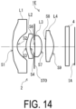
- FIG. 14 is a configuration diagram of an imaging lens 1E in Example 5 of the present disclosure.
- FIG. 15 is an aberration diagram of the imaging lens 1E illustrated in FIG. 14 at a wavelength of 940 nm.
- FIG. 16 is a graph showing a relative light amount with respect to the image height of the imaging lens 1E illustrated in FIG. 14 .
- the relative light amount indicates a ratio of the light amount at the image height position when the light amount at the optical axis position on the imaging surface IA is 100%.
- the imaging lens 1E of Example 5 includes the lens system 2 in which the first lens L1 having negative refractive power with the convex surface facing the object side and the concave surface facing the image side, the second lens L2 having positive refractive power with the convex surface facing the object side and the concave surface facing the image side, the aperture diaphragm STO, the third lens L3 having positive refractive power with the convex surface facing the object side and the convex surface facing the image side, and the fourth lens L4 having positive refractive power with the convex surface facing the object side and the convex surface facing the image side are arranged in order from the object side.
- Table 17 shows lens data of the imaging lens 1E of Example 5.
- SURFACE NUMBER R D Nd Vd 1 100.000 0.250 1.66059 20.40 2 0.656 0.470 3 0.867 0.224 1.66059 20.40 4 1.121 0.225 5(STO) INF 0.011 6 10.380 0.369 1.66059 20.40 7 -1.458 0.199 8 3.183 0.429 1.66059 20.40 9 -1.001 0.616 10 INF 0.210 1.51680 64.20 11 INF 0.296
- the focal length f, the F-number Fno, the half angle of view ⁇ , the maximum image height ImgH, and the total optical length TTL of the imaging lens 1E in Example 5 are shown in Table 20 below. [Table 20] INF f 0.67 Fno 1.6 ⁇ 64.92 ImgH 1.00 TTL 3.300
- FIG. 17 is a configuration diagram of an imaging lens 1F in Example 1 of the present disclosure.
- FIG. 18 is an aberration diagram of the imaging lens 1F illustrated in FIG. 17 at a wavelength of 940 nm.
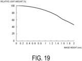
- FIG. 19 is a graph showing a relative light amount with respect to the image height of the imaging lens 1F illustrated in FIG. 17 .
- the relative light amount indicates a ratio of the light amount at the image height position when the light amount at the optical axis position on the imaging surface IA is 100%.
- the imaging lens 1F of Example 6 includes the lens system 2 in which the first lens L1 having negative refractive power with the convex surface facing the object side and the concave surface facing the image side, the second lens L2 having positive refractive power with the convex surface facing the object side and the concave surface facing the image side, the aperture diaphragm STO, the third lens L3 having positive refractive power with the convex surface facing the object side and the convex surface facing the image side, and the fourth lens L4 having positive refractive power with the convex surface facing the object side and the convex surface facing the image side are arranged in order from the object side.
- Table 21 shows lens data of the imaging lens 1F of Example 6.
- SURFACE NUMBER R D Nd Vd 1 199.500 0.499 1.57137 34.45 2 1.260 1.055 3 2.353 0.399 1.57137 34.45 4 3.105 0.331 5(STO) INF 0.000 6 9.999 1.609 1.57137 34.45 7 -1.762 0.359 8 2.381 0.668 1.57137 34.45 9 -99.750 1.054 10 INF 0.300 1.51680 64.20 11 INF 0.666
- the focal length f, the F-number Fno, the half angle of view ⁇ , the maximum image height ImgH, and the total optical length TTL of the imaging lens 1F in Example 6 are shown in Table 24 below. [Table 24] INF f 1.34 Fno 1.7 ⁇ 64.96 ImgH 2.00 TTL 6.940
- Table 25 shows corresponding values of the Conditional Expressions (1) to (7) in the lens systems of Examples 1 to 6.
- Tables 26 and 27 show numerical values related to the Conditional Expressions (1) to (7). As shown in Table 25, all of the Conditional Expressions (1) to (7) are satisfied in any of the examples.
- the lens system 2 in which the transmission light amount is secured and the aberration is corrected well can be realized in spite of having a wide angle of view of a half angle of view of 35 degrees or more.
- the light amount (peripheral light amount) at the position where the image height is high can be secured up to near 50% of the light amount at the optical axis position in spite of having a wide angle of view.
- An imaging lens including a lens system in which a first lens having negative refractive power with a concave surface facing an image side, a second lens having positive refractive power with a convex surface facing an object side, a diaphragm, a third lens having positive refractive power, and a fourth lens having positive refractive power with a convex surface facing an image side are arranged in order from the object side, in which the lens system satisfies conditional expressions of: ⁇ 3 ⁇ f 1 / f ⁇ ⁇ 1.15 2.4 ⁇ TTL / ImgH ⁇ 5 where f1 is the focal length of the first lens, f is the focal length of the lens system, TTL is the total length of the lens system, and ImgH is the maximum image height of the lens system.
- the imaging lens according to item 1 in which the lens system satisfies a conditional expression of: EPT / TTL ⁇ 0.3 where EPT is an entrance pupil position of the lens system.
- the imaging lens according to item 1 or 2 in which the lens system satisfies a conditional expression of: 0.05 ⁇ D 1 / f ⁇ 1 where D1 is a center thickness of the first lens.
- the imaging lens according to any one of items 1 to 3, in which the lens system satisfies a conditional expression of: f / EPD ⁇ 2.0 where EPD is an entrance pupil diameter of the lens system.
- the imaging lens according to any one of items 1 to 4, in which the lens system satisfies a conditional expression of: f 2 / f ⁇ 40 where f2 is a focal length of the second lens.
- the imaging lens according to any one of items 1 to 5, in which the lens system satisfies a conditional expression of: 1.5 ⁇ f 3 / f ⁇ 25 where f3 is a focal length of the third lens.
- the imaging device including a light source that emits light, and a light receiving element that receives, through the imaging lens, reflected light in which light from the light source is reflected by a subject, in which the imaging device is configured as a distance measurement sensor that calculates a distance to the subject by measuring a time from when the light source emits light to when the reflected light is received.
- the present disclosure is useful for providing an imaging lens having a wide angle of view and a high peripheral light amount while having a small size and a high resolution, and an imaging device provided with the imaging lens.
- the imaging device applied with the imaging lens of the present disclosure is not limited to the distance measurement sensor exemplified in the above embodiment.
- the present disclosure can also be applied to a camera for imaging that forms an image of visible light.
- the distance measurement sensor applied with the imaging lens of the present disclosure is, for example, a distance measurement sensor that receives reflected light of a light source that emits light of a single wavelength such as near-infrared light or visible light.
- the distance measurement sensor mounted with the imaging lens of the present disclosure is useful for providing, for example, an imaging assist function in an imaging camera such as background blurring and autofocus, an automatic drive technology of an automatic cleaner, an automobile, and the like, a face authentication technology, an AR space realization technology, and the like.
Landscapes
- Physics & Mathematics (AREA)
- General Physics & Mathematics (AREA)
- Engineering & Computer Science (AREA)
- Optics & Photonics (AREA)
- Electromagnetism (AREA)
- Computer Networks & Wireless Communication (AREA)
- Radar, Positioning & Navigation (AREA)
- Remote Sensing (AREA)
- Lenses (AREA)
Abstract
Description
- The present disclosure relates to an imaging lens and an imaging device equipped with the same.
- In recent years, as typified by the high performance of an imaging device mounted on a portable communication terminal such as a smartphone, an imaging lens having a smaller size and a high resolution is desired for an imaging device commonly mounted on an electronic device.
- Recently, more electronic devices are mounted with a distance measurement sensor such as a time of flight (ToF) sensor. Such a distance measurement sensor measures the distance to a subject by using a time from when light is emitted from a light source to when reflected light reflected by the subject is received by a light receiving element. Such a distance measurement sensor is also a type of imaging device, and causes a light receiving element to receive reflected light through an imaging lens. An imaging lens used for a distance measurement sensor is desired to be an imaging lens having a small size, a small F-number, and a high resolution. Furthermore, in recent years, there has been an increasing demand for an imaging lens having a wide angle of view and a high peripheral light amount for capturing a wider range.
- For example,
Patent Documents -
- Patent Document 1:
JP 4797115 A - Patent Document 2:
JP 6047701 A - The imaging lens described in
Patent Document 1 proposes a compact lens system having a wide angle of view. However, since the diaphragm is disposed behind a third lens and the entrance pupil position gets close to an imaging surface side, it is difficult to reduce the front lens diameter. If the total length is shortened, the light ray angle after the diaphragm becomes steeper, and it is difficult to secure the peripheral light amount. - The imaging lens described in
Patent Document 2 proposes a lens system having a wide angle of view and a high resolution. However, similarly toPatent Document 1, the diaphragm is disposed behind the third lens, and it is difficult to achieve both downsizing and securing the peripheral light amount. There remains a problem that the refractive power of the first lens is weak and it is difficult to downsize the front lens diameter. - The present disclosure has been made in view of the above problems, and an object of the present disclosure is to provide an imaging lens having a wide angle of view and a high peripheral light amount while having a small size and a high resolution, and an imaging device provided with the imaging lens.
- An imaging lens according to one embodiment of the present disclosure includes a lens system in which a first lens having negative refractive power with a concave surface facing an image side, a second lens having positive refractive power with a convex surface facing an object side, a diaphragm, a third lens having positive refractive power, and a fourth lens having positive refractive power with a convex surface facing an image side are arranged in order from the object side. The lens system satisfies conditional expressions of:


- An imaging device according to another aspect of the present disclosure includes an imaging lens having the above configuration.
- According to the present disclosure, it is possible to provide an imaging lens having a wide angle of view and a high peripheral light amount while having a small size and a high resolution, and an imaging device provided with the imaging lens.
-
-
FIG. 1 is a view illustrating a schematic configuration of a distance measurement sensor applied with an imaging lens according to one embodiment of the present disclosure. -
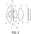
FIG. 2 is a configuration diagram of an imaging lens in Example 1 of the present disclosure. -
FIG. 3 is an aberration diagram of the imaging lens illustrated inFIG. 2 . -
FIG. 4 is a graph showing a relative light amount with respect to an image height of the imaging lens illustrated inFIG. 2 . -
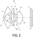
FIG. 5 is a configuration diagram of an imaging lens in Example 2 of the present disclosure. -
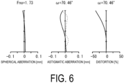
FIG. 6 is an aberration diagram of the imaging lens illustrated inFIG. 5 . -
FIG. 7 is a graph showing a relative light amount with respect to an image height of the imaging lens illustrated inFIG. 5 . -
FIG. 8 is a configuration diagram of an imaging lens in Example 3 of the present disclosure. -
FIG. 9 is an aberration diagram of the imaging lens illustrated inFIG. 8 . -
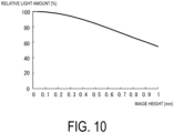
FIG. 10 is a graph showing a relative light amount with respect to an image height of the imaging lens illustrated inFIG. 8 . -
FIG. 11 is a configuration diagram of an imaging lens in Example 4 of the present disclosure. -
FIG. 12 is an aberration diagram of the imaging lens illustrated inFIG. 11 . -
FIG. 13 is a graph showing a relative light amount with respect to an image height of the imaging lens illustrated inFIG. 11 . -
FIG. 14 is a configuration diagram of an imaging lens in Example 5 of the present disclosure. -
FIG. 15 is an aberration diagram of the imaging lens illustrated inFIG. 14 . -
FIG. 16 is a graph showing a relative light amount with respect to an image height of the imaging lens illustrated inFIG. 14 . -
FIG. 17 is a configuration diagram of an imaging lens in Example 6 of the present disclosure. -
FIG. 18 is an aberration diagram of the imaging lens illustrated inFIG. 17 . -
FIG. 19 is a graph showing a relative light amount with respect to an image height of the imaging lens illustrated inFIG. 17 . - Hereinafter, one embodiment will be described with reference to the drawings. Note that the same or corresponding elements are denoted by the same reference signs throughout all the drawings, and redundant detailed description will be omitted. Hereinafter, an aspect in which an imaging device applied with the imaging lens of the present disclosure constitutes a distance measurement sensor will be exemplified.
-
FIG. 1 is a view illustrating a schematic configuration of a distance measurement sensor applied with an imaging lens according to one embodiment of the present disclosure. As illustrated inFIG. 1 , adistance measurement sensor 10 includes alight source 20, alight receiver 30, and acontroller 40. Thelight source 20 is a laser diode or a light emitting diode that emits near-infrared light, for example. The wavelength emitted by thelight source 20 is set within a range in which, for example, the lower limit value is 700 nm, preferably 800 nm, and the upper limit value is 1100 nm, preferably 1000 nm. Thelight source 20 is connected to thecontroller 40 via a drive unit (driver) 21. Thedrive unit 21 causes thelight source 20 to emit light in response to a drive signal from thecontroller 40. - The
light receiver 30 includes animaging lens 1 including alens system 2 described later, and animaging element 3 including a plurality of light receiving elements arranged on an imaging surface IA of theimaging lens 1. Note that theimaging lens 1 illustrated inFIG. 1 is the same as animaging lens 1A of Example 1 described later together withFIG. 2 . The plurality of light receiving elements constituting theimaging element 3 include photodiodes, for example. For example, theimaging element 3 is a charge coupled device (CCD) sensor, a complementary metal oxide semiconductor (CMOS) sensor, or the like. - The
controller 40 includes anarithmetic unit 41, aninput unit 42, anoutput unit 43, asignal transmission unit 44, asignal reception unit 45, and astorage unit 46. These components are configured to be able to transmit signals to one another via abus 47. Thecontroller 40 is configured as a computer including a CPU, a main memory (RAM), a storage, and a communication interface. Therefore, each of the above-describedcomponents - The
input unit 42 receives a control signal from the outside. For example, when thedistance measurement sensor 10 is mounted on a communication terminal such as a smartphone, theinput unit 42 receives, as a control signal, a distance measurement start signal from a higher-level processor in the communication terminal. When theinput unit 42 receives the control signal, thesignal transmission unit 44 outputs a drive signal for lighting thelight source 20. Thelight receiver 30 receives (images) reflected light in which light emitted from thelight source 20 is reflected by the subject. The imaging element 3 (light receiving element) converts reflected light received through theimaging lens 1 into an electric signal (imaging signal), and transmits the electric signal to thecontroller 40. Thesignal reception unit 45 receives the imaging signal from thelight receiver 30. - The
arithmetic unit 41 measures the time from when the light emitted by thelight source 20 is emitted to when the light is received by theimaging element 3, calculates the distance between thedistance measurement sensor 10 and the subject from the time and the light speed, and generates distance measurement data. By calculating the distance for each light receiving element (pixel) constituting theimaging element 3, thearithmetic unit 41 can output the distance measurement data as image data. Theoutput unit 43 outputs the distance measurement data calculated by thearithmetic unit 41 to the outside. For example, when mounted on the communication terminal as described above, thedistance measurement sensor 10 outputs the distance measurement data to the higher-level processor in the communication terminal. - The
imaging lens 1 according to the present embodiment includes thelens system 2 in which a first lens L1, a second lens L2, a diaphragm STO, a third lens L3, and a fourth lens L4 are arranged in order from an object side.FIG. 1 illustrates respective lens surfaces of thelens system 2 as S1, ..., S4, S6, ..., and S9 in order from the object side. For example, the lens surface S1 means a lens surface on the object side of the first lens L1, and the lens surface S2 means a lens surface on the image side of the first lens L1. - Note that, in the
imaging lens 1 illustrated inFIG. 1 , the lens surface S2 on the image side of the first lens L1 is a concave surface, the lens surface S3 on the object side of the second lens L2 is a convex surface, and the lens surface S9 on the image side of the fourth lens L4 is a convex surface. Abandpass filter 4 for transmitting near-infrared light is provided between the fourth lens L4 and the imaging surface IA (imaging element 3). Note that thebandpass filter 4 need not be provided. An optical member such as a sealing glass for protecting theimaging element 3 may be arranged at the position of thebandpass filter 4. - With the configuration of the
lens system 2, the angle of an off-axis light ray largely bent by the first lens L1 having negative refractive power can be guided to the imaging surface IA at a gentle angle by the positive lenses of the second lens L2 and subsequent lenses. By arranging the position of the diaphragm STO between the second lens L2 and the third lens L3, it is possible to minimize the cut amount of the off-axis light ray while reducing the front lens diameter, and thus it is easy to secure the peripheral light amount. - In the present embodiment, the
lens system 2 satisfies the following Conditional Expressions (1) and (2).

lens system 2, TTL is the total length of thelens system 2, and ImgH is the maximum image height of thelens system 2. - The Conditional Expression (1) defines the relationship between the focal length f1 of the first lens L1 and the focal length f of the
lens system 2. When the lower limit of the Conditional Expression (1) is exceeded, the negative refractive power of the first lens L1 becomes weak, and it is difficult to secure a wide angle of view with a short total length. When the upper limit of the Conditional Expression (1) is exceeded, on the other hand, the refractive power of the first lens becomes too strong, it is difficult to correct off-axis aberration, and good resolution performance cannot be obtained. The upper limit value of the Conditional Expression (1) is preferably -1.3, and the lower limit value of the Conditional Expression (1) is preferably -2.4. - The Conditional Expression (2) defines the relationship between the total length TTL and the maximum image height ImgH in the
lens system 2. By satisfying the Conditional Expression (2), it is possible to realize an optical system that is small in size but has the aberration corrected well. - In the present embodiment, the
lens system 2 can further satisfy the following Conditional Expression (3).
lens system 2. - The Conditional Expression (3) defines the relationship between the total length TTL and the entrance pupil position EPT in the
lens system 2. By bringing the entrance pupil position EPT close to the object side in thelens system 2 having a wide angle of view, it is possible to reduce the light ray height of an off-axis light flux passing through the first lens L1. On the other hand, when the upper limit of the Conditional Expression (3) is exceeded, the entrance pupil position EPT is too close to the image surface side, and therefore it is difficult to reduce the front lens diameter. Note that the entrance pupil position EPT is defined by the distance from a surface top on the object side in the first lens L1. - In the present embodiment, the
lens system 2 can further satisfy the following Conditional Expression (4).
- The Conditional Expression (4) defines the relationship between the center thickness D1 and the focal length L1 in the first lens L1. When the upper limit of the Conditional Expression (4) is exceeded, the volume of the first lens L1 is large, and it is difficult to reduce the weight, and it is also difficult to reduce the front lens diameter. When the lower limit of the Conditional Expression (4) is exceeded, on the other hand, the center thickness of the first lens L1 is too thin, and thus the possibility of deformation or cracking due to impact increases. By satisfying the Conditional Expression (4), it is possible to prevent deformation or cracking due to impact while achieving weight reduction and size reduction of the first lens L1. Note that the upper limit value of the Conditional Expression (4) is preferably 0.5, and the lower limit value of the Conditional Expression (4) is preferably 0.1.
- In the present embodiment, the
lens system 2 can further satisfy the following Conditional Expression (5).
lens system 2. - The Conditional Expression (5) defines the relationship between the focal length f and the entrance pupil diameter EPD in the
lens system 2, and is a conditional expression defining a so-called F-number. By satisfying the Conditional Expression (5), it is possible to secure a necessary light amount in a short exposure time even for an imaging element having a small size and a high definition. - In the present embodiment, the
lens system 2 can further satisfy the following Conditional Expression (6).
- The Conditional Expression (6) defines the relationship between the focal length f2 of the second lens L2 and the focal length f of the
lens system 2. When the upper limit of the Conditional Expression (6) is exceeded, the refractive power of the second lens L2 is weak with respect to the positive refractive power necessary for increasing the diameter and shortening the total length, and it becomes necessary to increase the refractive power of the third lens L3 and the fourth lens L4. Therefore, performance deterioration due to eccentricity errors of the third lens L3 and the fourth lens L4 that are actually produced increases. On the other hand, by satisfying the Conditional Expression (6), it is possible to effectively divide the positive refractive power necessary for shortening the total length and to suppress an eccentricity error while achieving a large diameter. Note that the upper limit value of the Conditional Expression (6) is preferably 25. - In the present embodiment, the
lens system 2 can further satisfy the following Conditional Expression (7).
- The Conditional Expression (7) defines the relationship between the focal length f3 of the third lens L3 and the focal length f of the
lens system 2. By satisfying the Conditional Expression (7), it is possible to effectively allocate the positive refractive power necessary for shortening the total length to the third lens L3 while achieving a large diameter. The amount of aberration generated in the third lens L3 can be suppressed, and performance deterioration due to an eccentricity error can be suppressed. - Hereinafter, examples of the
imaging lens 1 of the present disclosure will be described. Parameters used for each example are as follows. In lens data and tables of the specification data of the lens system, "degree" is used as the unit of angle, and "mm" is used as the unit of length. The calculation wavelength of the focal length is 940 nm. - f: focal length of the
lens system 2 - Fno: F-number (= f/Epd)
- ω: half angle of view
- ImgH: maximum image height
- TTL: total optical length of the lens system 2 (distance on optical axis from the lens surface S1 on the object side of the first lens L1 to the imaging surface IA)
- i: lens surface number (i = 1, ..., 4, 6, ..., 9)
- Ri: radius of curvature on the i-th lens surface
- Dik: center interval between the i-th lens surface Si and the k-th (k = i + 1) lens surface Sk
- nd: refractive index with respect to a d line of the lens material
- vd: Abbe number of the lens material
- Note that the notation of 5 (STO) in the lens surface number indicates that a diaphragm surface STO is located between the lens surface S4 and the lens surface S6. The surface number of an object side surface of the
bandpass filter 4 is 10, and the surface number of the image side surface of thebandpass filter 4 is 11. Note that "inf" in the radius of curvature indicates that the surface is a flat surface. - In each example, all the lens surfaces Si have an aspherical shape. Here, when a distance (sag amount) in the optical axis direction from a tangential plane of a surface vertex is X, a height from the optical axis is H, R is a radius of curvature, K is a conic constant, and Am is an m-th order aspherical coefficient, the aspherical shape is expressed by the following expression.

- Therefore, in the following, the value of Am in the aspheric expression described above is indicated, and the aspherical shape is specified. In the table of aspherical data, "E ± n" (n: natural number) of the numerical value of the aspherical coefficient is an exponential expression with a base of 10. That is, "E ± n" means "× 10±n".
-
FIG. 2 is a configuration diagram of theimaging lens 1A in Example 1 of the present disclosure.FIG. 3 is an aberration diagram of theimaging lens 1A illustrated inFIG. 2 at a wavelength of 940 nm.FIG. 4 is a graph showing a relative light amount with respect to the image height of theimaging lens 1A illustrated inFIG. 2 . The relative light amount indicates a ratio of the light amount at the image height position when the light amount at the optical axis position on the imaging surface IA is 100%. - The
imaging lens 1A of Example 1 includes thelens system 2 in which the first lens L1 having negative refractive power with the convex surface facing the object side and the concave surface facing the image side, the second lens L2 having positive refractive power with the convex surface facing the object side and the concave surface facing the image side, the aperture diaphragm STO, the third lens L3 having positive refractive power with the concave surface facing the object side and the convex surface facing the image side, and the fourth lens L4 having positive refractive power with the convex surface facing the object side and the convex surface facing the image side are arranged in order from the object side. - Table 1 shows lens data of the
imaging lens 1A of Example 1.[Table 1] SURFACE NUMBER R D Nd Vd 1 7.033 0.388 1.66059 20.40 2 0.997 0.864 3 2.470 0.312 1.66059 20.40 4 3.371 0.317 5(STO) INF 0.040 6 -5.072 0.910 1.66059 20.40 7 -2.273 0.381 8 4.182 1.365 1.66059 20.40 9 -1.564 1.260 10 INF 0.210 1.51680 64.20 11 INF 0.500 - The conic constant K and the aspherical coefficient Am in Example 1 are shown in Tables 2 and 3 below.
[Table 2] SURFACE NUMBER K A4 A6 A8 1 -3.08309E+01 9.68074E-02 -8.04353E-02 4.40911E-02 2 -2.69524E+00 3.56317E-01 -2.32950E-02 -5.54566E-01 3 -1.50138E+00 -8.08127E-03 -9.71243E-02 8.01357E-01 4 -1.10046E+01 1.12796E-01 3.53787E-02 9.81990E-01 6 -6.94187E-01 -1.64567E-02 4.30784E-02 2.02103E-01 7 -1.40107E+01 -1.98056E-01 1.73374E-01 -1.35550E-01 8 -1.19450E+01 -3.21049E-02 3.14093E-02 -1.49381E-02 9 -2.41515E-01 5.50034E-02 -3.27688E-03 1.98217E-03 [Table 3] SURFACE NUMBER A10 A12 A14 A16 1 -1.49316E-02 3.04272E-03 -3.43532E-04 1.66436E-05 2 8.89953E-01 -5.73720E-01 1.28243E-01 7.41217E-04 3 -2.22734E+00 3.64517E+00 -3.15545E+00 1.05084E+00 4 -2.20017E+00 3.06831E+00 0.00000E+00 0.00000E+00 6 0.00000E+00 0.00000E+00 0.00000E+00 0.00000E+00 7 5.82042E-02 0.00000E+00 0.00000E+00 0.00000E+00 8 4.51403E-03 -6.07514E-04 0.00000E+00 0.00000E+00 9 2.45168E-03 -1.28115E-03 2.51167E-04 0.00000E+00 - The focal length f, the F-number Fno, the half angle of view ω, the maximum image height ImgH, and the total optical length TTL of the
imaging lens 1A in Example 1 are shown in Table 4 below.[Table 4] INF f 1.04 Fno 1.45 ω 64.844 ImgH 1.55 TTL 6.046 -
FIG. 5 is a configuration diagram of animaging lens 1B in Example 2 of the present disclosure.FIG. 6 is an aberration diagram of theimaging lens 1B illustrated inFIG. 5 .FIG. 7 is a graph showing a relative light amount with respect to the image height of theimaging lens 1B illustrated inFIG. 5 . The relative light amount indicates a ratio of the light amount at the image height position when the light amount at the optical axis position on the imaging surface IA is 100%. - The
imaging lens 1B of Example 2 includes thelens system 2 in which the first lens L1 having negative refractive power with the convex surface facing the object side and the concave surface facing the image side, the second lens L2 having positive refractive power with the convex surface facing the object side and the concave surface facing the image side, the aperture diaphragm STO, the third lens L3 having positive refractive power with the concave surface facing the object side and the convex surface facing the image side, and the fourth lens L4 having positive refractive power with the convex surface facing the object side and the convex surface facing the image side are arranged in order from the object side. - Table 5 shows lens data of the
imaging lens 1B of Example 2.[Table 5] SURFACE NUMBER R D Nd Vd 1 1.474 0.300 1.57137 34.45 2 0.641 1.339 3 4.128 0.342 1.57137 34.45 4 6.237 0.693 5(STO) INF 0.030 6 -10.902 0.516 1.57137 34.45 7 -2.810 0.288 8 10.256 1.467 1.57137 34.45 9 -1.429 1.925 10 INF 0.300 1.51680 64.20 11 INF 0.300 - The conic constant K and the aspherical coefficient Am in Example 2 are shown in Tables 6 and 7 below.
[Table 6] SURFACE NUMBER K A4 A6 A8 1 -2.63714E+00 -6.71606E-02 3.67980E-02 -1.21035E-02 2 -1.16874E+00 -1.07917E-02 2.00791E-01 -3.83326E-01 3 5.54393E+00 3.86606E-02 8.25233E-02 -3.67229E-02 4 -9.78892E+00 9.54029E-02 1.37628E-01 -4.46930E-02 6 2.00000E+01 -3.41348E-02 1.91384E-02 8.17574E-03 7 -5.22688E+00 -9.36688E-02 5.85841E-02 -2.17981E-02 8 -1.17472E+01 -6.10932E-02 4.86984E-02 -2.10720E-02 9 -3.65584E+00 -1.02186E-01 6.26931E-02 -4.04957E-02 [Table 7] SURFACE NUMBER A10 A12 A14 A16 1 2.40066E-03 -2.77555E-04 1.72682E-05 -4.44831E-07 2 4.65649E-01 -2.84443E-01 7.95402E-02 -8.24634E-03 3 -1.65904E-02 5.71709E-02 -5.51163E-02 1.47711E-02 4 -2.67178E-02 5.59165E-02 0.00000E+00 0.00000E+00 6 0.00000E+00 0.00000E+00 0.00000E+00 0.00000E+00 7 1.24398E-02 0.00000E+00 0.00000E+00 0.00000E+00 8 1.01118E-02 -2.00597E-03 0.00000E+00 0.00000E+00 9 2.04806E-02 -6.18056E-03 9.51414E-04 0.00000E+00 - The focal length f, the F-number Fno, the half angle of view ω, the maximum image height ImgH, and the total optical length TTL of the
imaging lens 1B in Example 2 are shown in Table 8 below.[Table 8] INF f 1.25 Fno 1.73 ω 70.46 ImgH 2.15 TTL 7.500 -
FIG. 8 is a configuration diagram of an imaging lens 1C in Example 3 of the present disclosure.FIG. 9 is an aberration diagram of the imaging lens 1C illustrated inFIG. 8 .FIG. 10 is a graph showing a relative light amount with respect to the image height of the imaging lens 1C illustrated inFIG. 8 . The relative light amount indicates a ratio of the light amount at the image height position when the light amount at the optical axis position on the imaging surface IA is 100%. - The imaging lens 1C of Example 3 includes the
lens system 2 in which the first lens L1 having negative refractive power with the concave surface facing the object side and the concave surface facing the image side, the second lens L2 having positive refractive power with the convex surface facing the object side and the concave surface facing the image side, the aperture diaphragm STO, the third lens L3 having positive refractive power with the concave surface facing the object side and the convex surface facing the image side, and the fourth lens L4 having positive refractive power with the convex surface facing the object side and the convex surface facing the image side are arranged in order from the object side. - Table 9 shows lens data of the imaging lens 1C of Example 3.
[Table 9] SURFACE NUMBER R D Nd Vd 1 -0.842 0.250 1.57137 34.45 2 10.000 0.329 3 1.159 0.252 1.57137 34.45 4 1.357 0.219 5(STO) INF 0.030 6 -2.519 0.270 1.57137 34.45 7 -1.949 0.101 8 2.203 0.674 1.57137 34.45 9 -0.707 0.869 10 INF 0.210 1.51680 64.20 11 INF 0.296 - The conic constant K and the aspherical coefficient Am in Example 3 are shown in Tables 10 and Table 11 below.
[Table 10] SURFACE NUMBER K A4 A6 A8 1 -1.60167E+01 7.43220E-01 -1.40860E+00 1.79245E+00 2 -2.00000E+01 3.03629E+00 -1.21245E+01 5.05027E+01 3 -7.98681E-01 -3.47871E-03 -1.56318E+00 1.87768E+01 4 -4.32536E+00 4.49653E-01 7.34066E+00 -6.49670E+01 6 7.45604E+00 -5.31804E-01 2.20695E+00 -3.01119E+00 7 2.60775E+00 -1.15887E+00 4.71711E+00 -9.03122E+00 8 -1.97974E+01 -6.88623E-01 3.87121E+00 -8.91912E+00 9 -5.05752E-01 2.30409E-01 1.32865E-01 -2.26758E-01 [Table 11] SURFACE NUMBER A10 A12 A14 A16 1 -1.41987E+00 6.73689E-01 -1.74640E-01 1.89988E-02 2 -1.74118E+02 4.10673E+02 -5.24164E+02 2.62222E+02 3 -9.60856E+01 4.53710E+02 -1.20593E+03 1.10059E+03 4 5.91824E+02 -1.39429E+03 0.00000E+00 0.00000E+00 6 0.00000E+00 0.00000E+00 0.00000E+00 0.00000E+00 7 -7.25981E+00 0.00000E+00 0.00000E+00 0.00000E+00 8 1.15094E+01 -6.85302E+00 0.00000E+00 0.00000E+00 9 1.75182E+00 1.54352E+00 -3.96617E+00 0.00000E+00 - The focal length f, the F-number Fno, the half angle of view ω, the maximum image height ImgH, and the total optical length TTL of the imaging lens 1C in Example 3 are shown in Table 12 below.
[Table 12] INF f 0.75 Fno 1.7 ω 60.08 ImgH 1.00 TTL 3.500 -
FIG. 11 is a configuration diagram of animaging lens 1D in Example 4 of the present disclosure.FIG. 12 is an aberration diagram of theimaging lens 1D illustrated inFIG. 11 .FIG. 13 is a graph showing a relative light amount with respect to the image height of theimaging lens 1D illustrated inFIG. 11 . The relative light amount indicates a ratio of the light amount at the image height position when the light amount at the optical axis position on the imaging surface IA is 100%. - The
imaging lens 1D of Example 4 includes thelens system 2 in which the first lens L1 having negative refractive power with the convex surface facing the object side and the concave surface facing the image side, the second lens L2 having positive refractive power with the convex surface facing the object side and the concave surface facing the image side, the aperture diaphragm STO, the third lens L3 having positive refractive power with the concave surface facing the object side and the convex surface facing the image side, and the fourth lens L4 having positive refractive power with the convex surface facing the object side and the convex surface facing the image side are arranged in order from the object side. - Table 13 shows lens data of the
imaging lens 1D of Example 4.[Table 13] SURFACE NUMBER R D Nd Vd 1 10.211 0.250 1.57137 34.45 2 0.859 0.657 3 1.436 0.261 1.57137 34.45 4 1.738 0.462 5(STO) INF 0.030 6 -7.385 0.668 1.57137 34.45 7 -1.517 0.250 8 10.732 0.792 1.57137 34.45 9 -1.268 1.419 10 INF 0.210 1.51680 64.20 11 INF 0.300 - The conic constant K and the aspherical coefficient Am in Example 4 are shown in Tables 14 and Table 15 below.
[Table 14] SURFACE NUMBER K A4 A6 A8 1 3.01265E+00 1.05305E-01 -1.14957E-01 8.02930E-02 2 -1.87912E+00 2.89411E-01 2.09407E-01 -1.18845E+00 3 -1.10080E+00 -7.27559E-02 8.73449E-01 -4.38090E+00 4 2.14647E+00 6.18633E-02 1.23319E+00 -5.93236E+00 6 2.00000E+01 -7.98742E-02 -8.13337E-02 8.07873E-02 7 -2.37293E+00 -1.34650E-01 -1.26172E-01 1.79885E-01 8 1.70095E+00 -1.99780E-02 1.77766E-02 4.27258E-02 9 -4.75291E+00 -1.73905E-01 2.29808E-01 -2.20150E-01 [Table 15] SURFACE NUMBER A10 A12 A14 A16 1 -3.29549E-02 7.86621E-03 -9.97361E-04 5.12817E-05 2 1.62504E+00 -7.86229E-01 -6.06756E-02 9.83091E-02 3 1.15703E+01 -1.54388E+01 9.38491E+00 -2.01749E+00 4 1.75272E+01 -1.59887E+01 0.00000E+00 0.00000E+00 6 0.00000E+00 0.00000E+00 0.00000E+00 0.00000E+00 7 -2.29841E-01 0.00000E+00 0.00000E+00 0.00000E+00 8 -4.20990E-02 1.11347E-02 0.00000E+00 0.00000E+00 9 1.92050E-01 -9.11244E-02 1.66450E-02 0.00000E+00 - The focal length f, the F-number Fno, the half angle of view ω, the maximum image height ImgH, and the total optical length TTL of the
imaging lens 1D in Example 4 are shown in Table 16 below.[Table 16] INF f 1.04 Fno 1.7 ω 63.52 ImgH 1.50 TTL 5.300 -
FIG. 14 is a configuration diagram of animaging lens 1E in Example 5 of the present disclosure.FIG. 15 is an aberration diagram of theimaging lens 1E illustrated inFIG. 14 at a wavelength of 940 nm.FIG. 16 is a graph showing a relative light amount with respect to the image height of theimaging lens 1E illustrated inFIG. 14 . The relative light amount indicates a ratio of the light amount at the image height position when the light amount at the optical axis position on the imaging surface IA is 100%. - The
imaging lens 1E of Example 5 includes thelens system 2 in which the first lens L1 having negative refractive power with the convex surface facing the object side and the concave surface facing the image side, the second lens L2 having positive refractive power with the convex surface facing the object side and the concave surface facing the image side, the aperture diaphragm STO, the third lens L3 having positive refractive power with the convex surface facing the object side and the convex surface facing the image side, and the fourth lens L4 having positive refractive power with the convex surface facing the object side and the convex surface facing the image side are arranged in order from the object side. - Table 17 shows lens data of the
imaging lens 1E of Example 5.[Table 17] SURFACE NUMBER R D Nd Vd 1 100.000 0.250 1.66059 20.40 2 0.656 0.470 3 0.867 0.224 1.66059 20.40 4 1.121 0.225 5(STO) INF 0.011 6 10.380 0.369 1.66059 20.40 7 -1.458 0.199 8 3.183 0.429 1.66059 20.40 9 -1.001 0.616 10 INF 0.210 1.51680 64.20 11 INF 0.296 - The conic constant K and the aspherical coefficient Am in Example 5 are shown in Tables 18 and Table 19 below.
[Table 18] SURFACE NUMBER K A4 A6 A8 1 -4.00000E+01 4.64179E-01 -9.15678E-01 1.35985E+00 2 -2.08902E+00 9.98106E-01 4.91374E+00 -5.69409E+01 3 -4.05908E+00 3.95699E-01 -7.01625E+00 6.92098E+01 4 -5.84598E+00 2.33944E-01 1.27020E+00 -1.06492E+01 6 -2.00000E+01 -6.57160E-01 -1.21227E+00 4.12656E+00 7 1.10939E+00 -8.30555E-01 -2.05438E-01 -2.80532E-03 8 -2.00000E+01 -3.92794E-01 7.96204E-02 1.21305E+00 9 -6.16881E-01 2.24258E-01 -1.83851E-02 -9.46812E-01 [Table 19] SURFACE NUMBER A10 A12 A14 A16 1 -1.26742E+00 6.91427E-01 -2.00847E-01 2.36342E-02 2 2.76178E+02 -6.54998E+02 7.19682E+02 -2.93483E+02 3 -4.49373E+02 1.64843E+03 -3.07399E+03 2.23699E+03 4 3.78890E+01 3.33816E+02 0.00000E+00 0.00000E+00 6 0.00000E+00 0.00000E+00 0.00000E+00 0.00000E+00 7 -2.00228E+00 0.00000E+00 0.00000E+00 0.00000E+00 8 -2.53944E-02 -1.52441E+00 0.00000E+00 0.00000E+00 9 4.76303E+00 -5.36020E+00 1.21010E+00 0.00000E+00 - The focal length f, the F-number Fno, the half angle of view ω, the maximum image height ImgH, and the total optical length TTL of the
imaging lens 1E in Example 5 are shown in Table 20 below.[Table 20] INF f 0.67 Fno 1.6 ω 64.92 ImgH 1.00 TTL 3.300 -
FIG. 17 is a configuration diagram of animaging lens 1F in Example 1 of the present disclosure.FIG. 18 is an aberration diagram of theimaging lens 1F illustrated inFIG. 17 at a wavelength of 940 nm.FIG. 19 is a graph showing a relative light amount with respect to the image height of theimaging lens 1F illustrated inFIG. 17 . The relative light amount indicates a ratio of the light amount at the image height position when the light amount at the optical axis position on the imaging surface IA is 100%. - The
imaging lens 1F of Example 6 includes thelens system 2 in which the first lens L1 having negative refractive power with the convex surface facing the object side and the concave surface facing the image side, the second lens L2 having positive refractive power with the convex surface facing the object side and the concave surface facing the image side, the aperture diaphragm STO, the third lens L3 having positive refractive power with the convex surface facing the object side and the convex surface facing the image side, and the fourth lens L4 having positive refractive power with the convex surface facing the object side and the convex surface facing the image side are arranged in order from the object side. - Table 21 shows lens data of the
imaging lens 1F of Example 6.[Table 21] SURFACE NUMBER R D Nd Vd 1 199.500 0.499 1.57137 34.45 2 1.260 1.055 3 2.353 0.399 1.57137 34.45 4 3.105 0.331 5(STO) INF 0.000 6 9.999 1.609 1.57137 34.45 7 -1.762 0.359 8 2.381 0.668 1.57137 34.45 9 -99.750 1.054 10 INF 0.300 1.51680 64.20 11 INF 0.666 - The conic constant K and the aspherical coefficient Am in Example 6 are shown in Tables 22 and Table 23 below.
[Table 22] SURFACE NUMBER K A4 A6 A8 1 4.00000E+01 4.93812E-02 -2.10387E-02 6.93145E-03 2 -1.95645E+00 1.33030E-01 9.83182E-02 -2.70557E-01 3 -6.12848E+00 -2.38888E-02 -1.07449E-01 3.92673E-01 4 -5.82929E+00 -4.57555E-02 1.72109E-01 -4.51758E-01 6 -2.00000E+01 -6.01054E-02 -3.54061E-02 8.10621E-02 7 -1.25104E+00 -1.47475E-01 9.98065E-02 -6.43921E-02 8 -1.10956E+01 -3.87805E-02 2.30917E-02 -1.65430E-02 9 2.00000E+01 -9.54256E-03 -1.55740E-02 1.68917E-02 [Table 23] SURFACE NUMBER A10 A12 A14 A16 1 -1.49544E-03 1.94752E-04 -1.36459E-05 3.81965 E-07 2 3.21086E-01 -1.93386E-01 5.30722E-02 -5.25576E-03 3 -8.85313E-01 1.11156E+00 -6.74625E-01 1.54818 E-01 4 8.61059E-01 -3.11624E-01 0.00000E+00 0.00000E+00 6 0.00000E+00 0.00000E+00 0.00000E+00 0.00000E+00 7 1.62286E-02 0.00000E+00 0.00000E+00 0.00000E+00 8 6.61733E-03 -8.75386E-04 0.00000E+00 0.00000E+00 9 -9.05283E-03 2.94058E-03 -3.80094E-04 0.00000E+00 - The focal length f, the F-number Fno, the half angle of view ω, the maximum image height ImgH, and the total optical length TTL of the
imaging lens 1F in Example 6 are shown in Table 24 below.[Table 24] INF f 1.34 Fno 1.7 ω 64.96 ImgH 2.00 TTL 6.940 - Table 25 shows corresponding values of the Conditional Expressions (1) to (7) in the lens systems of Examples 1 to 6. Tables 26 and 27 show numerical values related to the Conditional Expressions (1) to (7). As shown in Table 25, all of the Conditional Expressions (1) to (7) are satisfied in any of the examples.
[Table 25] CONDITIONAL EXPRESSION (1) CONDITIONAL EXPRESSION (2) CONDITIONAL EXPRESSION (3) CONDITIONAL EXPRESSION (4) CONDITIONAL EXPRESSION (5) CONDITIONAL EXPRESSION (6) CONDITIONAL EXPRESSION (7) Example 1 -1.809 3.901 0.179 0.373 1.45 12.372 5.547 Example 2 -1.868 3.488 0.202 0.240 1.73 16.557 5.311 Example 3 -1.843 3.500 0.161 0.333 1.70 13.052 17.620 Example 4 -1.633 3.533 0.177 0.240 1.70 10.888 3.163 Example 5 -1.555 3.300 0.194 0.373 1.60 6.708 3.044 Example 6 -1.704 3.470 0.187 0.373 1.70 10.953 2.114 [Table 26] f f1 f2 f3 f4 Example 1 1.039 -1.878 12.850 5.761 1.976 Example 2 1.250 -2.335 20.696 6.638 2.355 Example 3 0.750 -1.382 9.789 13.215 1.017 Example 4 1.040 -1.698 11.324 3.290 2.084 Example 5 0.670 -1.042 4.494 2.039 1.250 Example 6 1.337 -2.277 14.640 2.825 4.181 [Table 27] TTL ImgH EPT EPD D1 Example 1 6.046 1.550 1.080 0.716 0.388 Example 2 7.500 2.150 1.513 0.723 0.300 Example 3 3.500 1.000 0.563 0.441 0.250 Example 4 5.300 1.500 0.937 0.612 0.250 Example 5 3.300 1.000 0.642 0.419 0.250 Example 6 6.940 2.000 1.299 0.787 0.499 - As illustrated in the aberration diagrams (
FIGS. 3 ,6 ,9 ,12 ,15 ,18 , and19 ) of the respective examples, thelens system 2 in which the transmission light amount is secured and the aberration is corrected well can be realized in spite of having a wide angle of view of a half angle of view of 35 degrees or more. As shown in the graphs (FIGS. 4 ,7 ,10 ,13 ,16 , and19 ) of the peripheral light amount with respect to the image height of the imaging lens of the respective examples, the light amount (peripheral light amount) at the position where the image height is high can be secured up to near 50% of the light amount at the optical axis position in spite of having a wide angle of view. - Although the embodiments of the present disclosure have been described above, configurations, combinations thereof, and the like in each embodiment are merely examples, and addition, omission, substitution, and other changes of the configurations can be appropriately made without departing from the gist of the present disclosure. The present disclosure is not limited by the embodiments, but is limited only by the claims.
- Each of the following items is a disclosure of a preferred embodiment of the present disclosure.
- An imaging lens including a lens system in which a first lens having negative refractive power with a concave surface facing an image side, a second lens having positive refractive power with a convex surface facing an object side, a diaphragm, a third lens having positive refractive power, and a fourth lens having positive refractive power with a convex surface facing an image side are arranged in order from the object side, in which the lens system satisfies conditional expressions of:


- The imaging lens according to
item 1, in which the lens system satisfies a conditional expression of:
- The imaging lens according to
item 
- The imaging lens according to any one of
items 1 to 3, in which the lens system satisfies a conditional expression of:
- The imaging lens according to any one of
items 1 to 4, in which the lens system satisfies a conditional expression of:
- The imaging lens according to any one of
items 1 to 5, in which the lens system satisfies a conditional expression of:
- An imaging device including the imaging lens according to any one of
items 1 to 6. - The imaging device according to
item 7 including a light source that emits light, and a light receiving element that receives, through the imaging lens, reflected light in which light from the light source is reflected by a subject, in which the imaging device is configured as a distance measurement sensor that calculates a distance to the subject by measuring a time from when the light source emits light to when the reflected light is received. - The present disclosure is useful for providing an imaging lens having a wide angle of view and a high peripheral light amount while having a small size and a high resolution, and an imaging device provided with the imaging lens. The imaging device applied with the imaging lens of the present disclosure is not limited to the distance measurement sensor exemplified in the above embodiment. For example, the present disclosure can also be applied to a camera for imaging that forms an image of visible light. The distance measurement sensor applied with the imaging lens of the present disclosure is, for example, a distance measurement sensor that receives reflected light of a light source that emits light of a single wavelength such as near-infrared light or visible light. The distance measurement sensor mounted with the imaging lens of the present disclosure is useful for providing, for example, an imaging assist function in an imaging camera such as background blurring and autofocus, an automatic drive technology of an automatic cleaner, an automobile, and the like, a face authentication technology, an AR space realization technology, and the like.
-
- 1, 1A, 1B, 1C, 1D, 1E, 1F Imaging lens
- 2 Lens system
- 3 Imaging element (light receiving element)
- 10 Distance measurement sensor (imaging device)
- 20 Light source
- L1 First lens
- L2 Second lens
- L3 Third lens
- L4 Fourth lens
- STO Diaphragm
Claims (8)
- An imaging lens comprising:a lens system in which a first lens having negative refractive power with a concave surface facing an image side, a second lens having positive refractive power with a convex surface facing an object side, a diaphragm, a third lens having positive refractive power, and a fourth lens having positive refractive power with a convex surface facing an image side are arranged in order from the object side,wherein the lens system satisfies conditional expressions of:where f1 is a focal length of the first lens, f is a focal length of the lens system, TTL is a total length of the lens system, and ImgH is a maximum image height of the lens system.


- The imaging lens according to claim 1, wherein the lens system satisfies a conditional expression of:

- The imaging lens according to claim 1 or 2, wherein the lens system satisfies a conditional expression of:

- The imaging lens according to claim 1 or 2, wherein the lens system satisfies a conditional expression of:

- The imaging lens according to claim 1 or 2, wherein the lens system satisfies a conditional expression of:

- The imaging lens according to claim 1 or 2, wherein the lens system satisfies a conditional expression of:

- An imaging device comprising the imaging lens according to claim 1 or 2.
- The imaging device according to claim 7, comprising:a light source configured to emit light; anda light receiving element configured to receive, through the imaging lens, reflected light where light from the light source is reflected by a subject,wherein the imaging device is configured as a distance measurement sensor that calculates a distance to the subject by measuring a time from when the light source emits light to when the reflected light is received.
Applications Claiming Priority (2)
| Application Number | Priority Date | Filing Date | Title |
|---|---|---|---|
| JP2022086269A JP2023173784A (en) | 2022-05-26 | 2022-05-26 | Imaging lens and imaging device equipped with the same |
| PCT/JP2023/018605 WO2023228860A1 (en) | 2022-05-26 | 2023-05-18 | Imaging lens and imaging device equipped with same |
Publications (2)
| Publication Number | Publication Date |
|---|---|
| EP4535059A1 true EP4535059A1 (en) | 2025-04-09 |
| EP4535059A4 EP4535059A4 (en) | 2026-05-13 |
Family
ID=88919220
Family Applications (1)
| Application Number | Title | Priority Date | Filing Date |
|---|---|---|---|
| EP23811733.7A Pending EP4535059A4 (en) | 2022-05-26 | 2023-05-18 | IMAGE LENS AND IMAGE DEVICE EQUIPPED WITH IT |
Country Status (3)
| Country | Link |
|---|---|
| EP (1) | EP4535059A4 (en) |
| JP (1) | JP2023173784A (en) |
| WO (1) | WO2023228860A1 (en) |
Family Cites Families (2)
| Publication number | Priority date | Publication date | Assignee | Title |
|---|---|---|---|---|
| CN110716289B (en) * | 2019-12-12 | 2020-03-31 | 江西联创电子有限公司 | Optical imaging lens |
| JP2021124725A (en) * | 2020-01-31 | 2021-08-30 | 株式会社デンソー | Light detection device |
-
2022
- 2022-05-26 JP JP2022086269A patent/JP2023173784A/en active Pending
-
2023
- 2023-05-18 WO PCT/JP2023/018605 patent/WO2023228860A1/en not_active Ceased
- 2023-05-18 EP EP23811733.7A patent/EP4535059A4/en active Pending
Also Published As
| Publication number | Publication date |
|---|---|
| EP4535059A4 (en) | 2026-05-13 |
| JP2023173784A (en) | 2023-12-07 |
| WO2023228860A1 (en) | 2023-11-30 |
Similar Documents
| Publication | Publication Date | Title |
|---|---|---|
| US11237357B2 (en) | Photographing optical lens assembly | |
| US10712540B2 (en) | Imaging lens | |
| US11899182B2 (en) | Imaging lens system and imaging device comprising seven lenses of −−++−+-refractive powers | |
| US7957075B2 (en) | Optical lens system for taking image | |
| US8611023B2 (en) | Photographing optical lens assembly | |
| US9383552B2 (en) | Optical imaging lens and electronic device comprising the same | |
| US8130455B2 (en) | Image pickup lens, image pickup unit, and mobile terminal | |
| US9285565B2 (en) | Imaging lens and imaging apparatus equipped with the imaging lens | |
| US8810923B2 (en) | Image capturing lens and image capturing apparatus provided with the image capturing lens | |
| CN101276038B (en) | Imaging lens, camera module, and portable terminal apparatus | |
| JP5951739B2 (en) | Optical imaging lens set | |
| JP7748200B2 (en) | Imaging lens system and imaging device | |
| US11209631B2 (en) | Lens unit, imaging apparatus, and mobile device | |
| JP6952830B2 (en) | Imaging lens system | |
| KR102048984B1 (en) | Small telephoto optical system | |
| US9279956B2 (en) | Optical imaging lens and electronic device comprising the same | |
| US20190265443A1 (en) | Optical lens system | |
| JP7749352B2 (en) | Imaging lens systems, camera modules, in-vehicle systems, mobile objects | |
| EP4170406A1 (en) | Optical imaging lens | |
| JPWO2009122897A1 (en) | Imaging lens, imaging device, and portable terminal | |
| US20160139362A1 (en) | Imaging Lens And Imaging Device | |
| JP7810838B2 (en) | Imaging lens system and imaging device | |
| EP4495655A1 (en) | Imaging lens and imaging device provided therewith | |
| CN213423582U (en) | Optical imaging system, lens module and electronic equipment | |
| WO2023228860A1 (en) | Imaging lens and imaging device equipped with same |
Legal Events
| Date | Code | Title | Description |
|---|---|---|---|
| STAA | Information on the status of an ep patent application or granted ep patent |
Free format text: STATUS: THE INTERNATIONAL PUBLICATION HAS BEEN MADE |
|
| PUAI | Public reference made under article 153(3) epc to a published international application that has entered the european phase |
Free format text: ORIGINAL CODE: 0009012 |
|
| STAA | Information on the status of an ep patent application or granted ep patent |
Free format text: STATUS: REQUEST FOR EXAMINATION WAS MADE |
|
| 17P | Request for examination filed |
Effective date: 20240919 |
|
| AK | Designated contracting states |
Kind code of ref document: A1 Designated state(s): AL AT BE BG CH CY CZ DE DK EE ES FI FR GB GR HR HU IE IS IT LI LT LU LV MC ME MK MT NL NO PL PT RO RS SE SI SK SM TR |
|
| DAV | Request for validation of the european patent (deleted) | ||
| DAX | Request for extension of the european patent (deleted) | ||
| A4 | Supplementary search report drawn up and despatched |
Effective date: 20260415 |
|
| RIC1 | Information provided on ipc code assigned before grant |
Ipc: G02B 13/04 20060101AFI20260409BHEP Ipc: G02B 13/00 20060101ALI20260409BHEP Ipc: G02B 13/18 20060101ALI20260409BHEP Ipc: G02B 9/34 20060101ALI20260409BHEP Ipc: G01C 3/00 20060101ALI20260409BHEP |