EP4535056A1 - Optical fiber ribbon - Google Patents
Optical fiber ribbon Download PDFInfo
- Publication number
- EP4535056A1 EP4535056A1 EP23816112.9A EP23816112A EP4535056A1 EP 4535056 A1 EP4535056 A1 EP 4535056A1 EP 23816112 A EP23816112 A EP 23816112A EP 4535056 A1 EP4535056 A1 EP 4535056A1
- Authority
- EP
- European Patent Office
- Prior art keywords
- optical fiber
- optical fibers
- fiber ribbon
- optical
- core
- Prior art date
- Legal status (The legal status is an assumption and is not a legal conclusion. Google has not performed a legal analysis and makes no representation as to the accuracy of the status listed.)
- Pending
Links
Images



Classifications
-
- G—PHYSICS
- G02—OPTICS
- G02B—OPTICAL ELEMENTS, SYSTEMS OR APPARATUS
- G02B6/00—Light guides; Structural details of arrangements comprising light guides and other optical elements, e.g. couplings
- G02B6/44—Mechanical structures for providing tensile strength and external protection for fibres, e.g. optical transmission cables
- G02B6/4401—Optical cables
- G02B6/4403—Optical cables with ribbon structure
-
- G—PHYSICS
- G02—OPTICS
- G02B—OPTICAL ELEMENTS, SYSTEMS OR APPARATUS
- G02B6/00—Light guides; Structural details of arrangements comprising light guides and other optical elements, e.g. couplings
- G02B6/02—Optical fibres with cladding with or without a coating
- G02B6/02295—Microstructured optical fibre
- G02B6/02314—Plurality of longitudinal structures extending along optical fibre axis, e.g. holes
- G02B6/02319—Plurality of longitudinal structures extending along optical fibre axis, e.g. holes characterised by core or core-cladding interface features
- G02B6/02323—Core having lower refractive index than cladding, e.g. photonic band gap guiding
- G02B6/02328—Hollow or gas filled core
Definitions
- Patent Literature 1 discloses a multi-core optical fiber in which skew among signal lights propagating through a plurality of cores is 1 ps/m or less, and a transmission constant difference between two cores adjacent to each other among the plurality of cores is larger than zero.
- An optical fiber ribbon includes a plurality of optical fibers each including a core and cladding, in which the core is formed of pure quartz or formed as a hollow core, the optical fibers arranged in parallel and adjacent to each other are coupled to each other, and a difference between a maximum value and a minimum value of light transmission time in the plurality of optical fibers is 0.1% or less of an average value of the light transmission time in the optical fibers.
- An object of the present disclosure is to provide an optical fiber ribbon capable of further reducing skew among cores and increasing a light transmission speed in the cores.
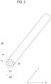
- Each of the optical fibers 10 is, for example, a single core fiber (SCF), and includes one core 11, cladding 12 covering the core 11, and a coating layer 14 covering the cladding 12.
- the core 11 has a refractive index higher than a refractive index of the cladding 12 and is configured to guide light.
- the coating layer 14 includes, for example, two layers of an ultraviolet curable resin layer and a colored layer.
- the core 11 is formed of pure quartz. As an addition amount of a dopant in the core 11 decreases, the light transmission speed increases. Therefore, when the core 11 is formed of pure quartz as described above, the light transmission speed can be increased compared to the case where a material of the core 11 includes a material other than quartz such as germanium. In addition, when the core 11 does not contain a dopant, it is possible to substantially eliminate variations in the addition amount of dopant, and therefore, it is easy to make the light transmission speed uniform.
- the twelve cores 11 and the cladding 12 in the optical fiber ribbon 1 are formed using the same preform. Accordingly, it is possible to reduce the difference in refractive index among the twelve optical fibers 10 and to reduce the skew which is the difference in the light transmission speed.
- the tension of the plurality of optical fibers 10 is controlled to be equal.
- control such that the tension becomes equal to a set value is referred to as "tension control”.
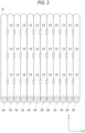
- FIG. 3 is a diagram illustrating an example of a modification of the optical fiber ribbon according to the embodiment of the present disclosure.
- an extending direction of the optical fiber 10 is referred to as a Y direction
- a direction in which the plurality of optical fibers 10 are arranged is referred to as an X direction.
- optical fiber ribbon according to the embodiment of the present disclosure is not limited to the configuration illustrated in FIG. 1 .
- optical fibers adjacent to each other of the optical fiber ribbon may be intermittently bonded to each other.
- the optical fibers 10 adjacent to each other are bonded by, for example, a plurality of bonding members 13 intermittently provided in a part of the Y direction instead of the coupling member 20 illustrated in FIG. 1 , as illustrated in FIG. 3 .
- the flexibility of the optical fiber ribbon 2 can be enhanced, and as illustrated in FIG. 4 , even when the optical fiber ribbon 2 is rounded or bundled in a cross-sectional view, the transmission loss is not deteriorated, and therefore, the optical cable 100 accommodated at high density can be formed.
- each of optical fibers 30 and 40 may include a plurality of cores 11, that is, may be multi-core fibers (MCF).
- MCF multi-core fibers
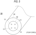
- the optical fiber 30 may include four cores 11 inside the cladding 12, as illustrated in FIG. 5 .
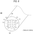
- the optical fiber 40 may include twelve cores 11 inside the cladding 12, as illustrated in FIG. 6 .
- the optical fibers 30 and 40 are MCFs, so that the lengths of the cores 11 in the same optical fibers 30 and 40 are the same, and therefore, the difference in length of the cores can be reduced (to substantially zero) and the transmission amount can be increased.
- the core can be mounted at a higher density.
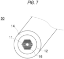
- FIG. 7 is a diagram illustrating an example of another modification of the optical fiber according to the embodiment of the present disclosure.
- the core 11 in the optical fiber 50 may be formed as a hollow core instead of being formed of pure quartz.
- FIG. 7 illustrates, as an example, a photonic band gap fiber (PBGF) in which holes 16 are regularly arranged around the core 11 which is a hollow core. In this manner, the transmission speed can be further increased by forming the core 11 as a hollow core.
- PBGF photonic band gap fiber
- FIG. 8 is a diagram illustrating an outline of a measurement system used in the measurement.
- the optical fiber ribbon or the optical fiber used for the measurement is also referred to as a "measurement target”.
- one end of the measurement target is connected to a light source that emits light having a wavelength of 1,550 nm via an FC connector, and the other end of the measurement target is connected to a light receiver via the FC connector.
- the light source is connected to a modulator, and the light receiver is connected to a vector bolt meter.
- the modulator is electrically connected to the vector bolt meter and transmits a reference signal.
- the measurement target 3 is an optical fiber ribbon obtained by coupling, in parallel, twelve optical fibers which are SCFs as illustrated in FIG. 3 .
- the plurality of optical fibers adjacent to each other are intermittently bonded as illustrated in FIG. 3 .
- the plurality of glass fibers in the measurement target 3 are selected at the time of formation from the preform.
- the twelve optical fibers in the measurement target 3 are not subjected to the tension control for equalizing the tensions of the plurality of optical fibers when being formed as an optical fiber ribbon.
- the difference between the maximum value and the minimum value of the light transmission time in the twelve optical fibers is 0.10% of the average value of the light transmission time in the optical fibers.
- the measurement target 4 is an optical fiber ribbon obtained by coupling, in parallel, twelve optical fibers which are SCFs. The optical fibers adjacent to each other are intermittently bonded.
- the plurality of glass fibers in the measurement target 4 are selected at the time of formation from the preform.
- the twelve optical fibers in the measurement target 4 are subjected to the tension control when being formed as an optical fiber ribbon.
- the difference between the maximum value and the minimum value of the light transmission time in the twelve optical fibers is 0.05% of the average value of the light transmission time in the optical fibers.
- the use of MCF can further reduce the skew among the optical fibers rather than the use of SCF.
- the skew among the plurality of cores in the same optical fiber is also reduced.
- the core included in each optical fiber is formed of the hollow core in FIG. 7 instead of pure quartz, the same result as in the case where the core of pure quartz is used is obtained.
Landscapes
- Physics & Mathematics (AREA)
- General Physics & Mathematics (AREA)
- Optics & Photonics (AREA)
- Mechanical Coupling Of Light Guides (AREA)
Abstract
Description
- The present disclosure relates to an optical fiber ribbon.
- The present application claims priority based on
Japanese Patent Application No. 2022-088640 filed on May 31, 2022 - In the related art, there has been developed an optical fiber for reducing skew among cores included in each of a plurality of optical fibers or among a plurality of cores included in the same optical fiber. For example,
Patent Literature 1 discloses a multi-core optical fiber in which skew among signal lights propagating through a plurality of cores is 1 ps/m or less, and a transmission constant difference between two cores adjacent to each other among the plurality of cores is larger than zero. - Patent Literature 1:
JP2013-228548A - An optical fiber ribbon according to the present disclosure includes a plurality of optical fibers each including a core and cladding, in which the core is formed of pure quartz or formed as a hollow core, the optical fibers arranged in parallel and adjacent to each other are coupled to each other, and a difference between a maximum value and a minimum value of light transmission time in the plurality of optical fibers is 0.1% or less of an average value of the light transmission time in the optical fibers.
-
- [
FIG. 1] FIG. 1 is a diagram illustrating an example of an optical fiber ribbon according to an embodiment of the present disclosure. - [
FIG. 2] FIG. 2 is a diagram illustrating a configuration of an optical fiber illustrated inFIG. 1 . - [
FIG. 3] FIG. 3 is a diagram illustrating an example of a modification of the optical fiber ribbon according to the embodiment of the present disclosure. - [
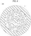
FIG. 4] FIG. 4 is a diagram illustrating an example of an optical cable using the optical fiber ribbon illustrated inFIG. 3 . - [
FIG. 5] FIG. 5 is a diagram illustrating an example of a modification of the optical fiber according to the embodiment of the present disclosure. - [
FIG. 6] FIG. 6 is a diagram illustrating an example of another modification of the optical fiber according to the embodiment of the present disclosure. - [
FIG. 7] FIG. 7 is a diagram illustrating an example of another modification of the optical fiber according to the embodiment of the present disclosure. - [
FIG. 8] FIG. 8 is a diagram illustrating an outline of a measurement system used for measuring a difference in light transmission time among the optical fibers. - [
FIG. 9] FIG. 9 is a diagram illustrating a list of measurement targets and measurement results of measurement using the measurement system illustrated inFIG. 8 . - In order to further improve the performance of the optical fiber ribbon, there is a demand for a technique capable of further reducing skew among cores and increasing a light transmission speed in the cores.
- An object of the present disclosure is to provide an optical fiber ribbon capable of further reducing skew among cores and increasing a light transmission speed in the cores.
- According to the present disclosure, it is possible to further reduce the skew among the cores and to increase the light transmission speed in the cores.
- First, an embodiment of the present disclosure will be listed and described.
- An optical fiber ribbon according to the embodiment of the present disclosure includes
- (1) a plurality of optical fibers each including a core and cladding, in which
- the core is formed of pure quartz or formed as a hollow core,
- the optical fibers arranged in parallel and adjacent to each other are coupled to each other, and
- a difference between a maximum value and a minimum value of light transmission time in the plurality of optical fibers is 0.1% or less of an average value of the light transmission time in the optical fibers.
- (2) In the optical fiber ribbon according to (1),
the difference may be 0.05% or less of the average value.
With such a configuration, it is possible to further reduce the skew among the cores. - (3) In the optical fiber ribbon according to (1) or (2),
the plurality of optical fibers adjacent to each other may be intermittently bonded.
With such a configuration, the optical fiber ribbon can be made more flexible, rounded, and bundled, and an optical fiber ribbon that is easy to route can be implemented. - (4) In the optical fiber ribbon according to any of (1) to (3),
each of the optical fibers may include a plurality of the cores.
With such a configuration of the multi-core fiber, the lengths of the cores are the same, and therefore, the difference in length of the cores can be reduced (to substantially zero) and the transmission amount can be increased. - (5) In the optical fiber ribbon according to any of (1) to (4),
- the optical fiber may have an outer diameter of 200 µm or less, and
- the cladding of the optical fiber may have an outer diameter of 100 µm or less.
- With such a configuration, it is possible to provide an optical fiber ribbon which implements high density, is easy to route, and is hardly bent and broken.
- A specific example of an optical fiber ribbon according to the present disclosure will be described below with reference to the drawings. The present disclosure is not limited to these exemplifications, but is indicated by the scope of claims, and is intended to include all modifications within a scope and meaning equivalent to the scope of claims.
-
FIG. 1 is a diagram illustrating an example of an optical fiber ribbon according to an embodiment of the present disclosure. With reference toFIG. 1 , anoptical fiber ribbon 1 according to the embodiment of the present disclosure includes a plurality ofoptical fibers 10 and acoupling member 20 configured to couple the plurality ofoptical fibers 10. In the example illustrated inFIG. 1 , theoptical fiber ribbon 1 includes twelveoptical fibers 10. Thecoupling member 20 covers the entire twelveoptical fibers 10 so that the adjacentoptical fibers 10 arranged in parallel are coupled to each other. - Each of the
optical fibers 10 is, for example, a single core fiber (SCF), and includes onecore 11, cladding 12 covering thecore 11, and acoating layer 14 covering thecladding 12. Thecore 11 has a refractive index higher than a refractive index of thecladding 12 and is configured to guide light. Thecoating layer 14 includes, for example, two layers of an ultraviolet curable resin layer and a colored layer. - More specifically, the
core 11 is formed of pure quartz. As an addition amount of a dopant in thecore 11 decreases, the light transmission speed increases. Therefore, when thecore 11 is formed of pure quartz as described above, the light transmission speed can be increased compared to the case where a material of thecore 11 includes a material other than quartz such as germanium. In addition, when thecore 11 does not contain a dopant, it is possible to substantially eliminate variations in the addition amount of dopant, and therefore, it is easy to make the light transmission speed uniform. - The twelve
cores 11 and thecladding 12 in theoptical fiber ribbon 1 are formed using the same preform. Accordingly, it is possible to reduce the difference in refractive index among the twelveoptical fibers 10 and to reduce the skew which is the difference in the light transmission speed. - Further, when the twelve
optical fibers 10 are formed as theoptical fiber ribbon 1, the tension of the plurality ofoptical fibers 10 is controlled to be equal. Hereinafter, control such that the tension becomes equal to a set value is referred to as "tension control". By performing such tension control, the difference in the lengths of the twelveoptical fibers 10 included in the sameoptical fiber ribbon 1 can be suppressed, and as a result, the skew can be further reduced. -
FIG. 2 is a diagram illustrating a configuration of theoptical fiber 10 illustrated inFIG. 1 . InFIG. 2 , an outer diameter D1 of thecladding 12 is formed to be, for example, 100 µm or less. By reducing a cladding diameter (glass diameter of optical fiber), it is possible to suppress breakage due to bending. An outer diameter D2 of theoptical fiber 10 is formed to be, for example, 200 µm or less. With such a configuration, the density of theoptical fiber 10 can be increased. - The
optical fiber ribbon 1 is not limited to a configuration including twelveoptical fibers 10, and may include, for example, twenty-fouroptical fibers 10 or fouroptical fibers 10. - The
coupling member 20 is not limited to the configuration covering the entire twelveoptical fibers 10 as illustrated inFIG. 1 , and may be a configuration coupling a part of theoptical fibers 10 adjacent to each other, for example. -
FIG. 3 is a diagram illustrating an example of a modification of the optical fiber ribbon according to the embodiment of the present disclosure. InFIG. 3 , an extending direction of theoptical fiber 10 is referred to as a Y direction, and a direction in which the plurality ofoptical fibers 10 are arranged is referred to as an X direction. - The optical fiber ribbon according to the embodiment of the present disclosure is not limited to the configuration illustrated in
FIG. 1 . For example, optical fibers adjacent to each other of the optical fiber ribbon may be intermittently bonded to each other. Specifically, in theoptical fiber ribbon 2 according to the modification, theoptical fibers 10 adjacent to each other are bonded by, for example, a plurality ofbonding members 13 intermittently provided in a part of the Y direction instead of thecoupling member 20 illustrated inFIG. 1 , as illustrated inFIG. 3 . -
FIG. 4 is a diagram illustrating an example of an optical cable using theoptical fiber ribbon 2 illustrated inFIG. 3 . Referring toFIG. 4 , anoptical cable 100 includes, for example, twooptical fiber ribbons 2 each including twelveoptical fibers 10, acable sheath 3 covering the twooptical fiber ribbons 2, and a plurality oftensile strength members 15 in which aramid fibers and the like are assembled. - As described above, with the configuration in which the
optical fibers 10 adjacent to each other are intermittently bonded to each other, the flexibility of theoptical fiber ribbon 2 can be enhanced, and as illustrated inFIG. 4 , even when theoptical fiber ribbon 2 is rounded or bundled in a cross-sectional view, the transmission loss is not deteriorated, and therefore, theoptical cable 100 accommodated at high density can be formed. - The plurality of
optical fibers 10 adjacent to each other are not limited to the configuration in which the optical fibers are intermittently bonded to each other, and for example, the bondingmember 13 may be provided over the entire Y direction illustrated inFIG. 3 between a part of the optical fibers. Theoptical cable 100 may not include thetensile strength member 15. - The optical fiber according to the embodiment of the present disclosure is not limited to SCF as illustrated in
FIG. 2 .FIGS. 5 and6 are diagrams illustrating an example of a modification of the optical fiber according to the embodiment of the present disclosure. Referring toFIGS. 5 and6 , each ofoptical fibers cores 11, that is, may be multi-core fibers (MCF). - For example, the
optical fiber 30 may include fourcores 11 inside thecladding 12, as illustrated inFIG. 5 . In addition, theoptical fiber 40 may include twelvecores 11 inside thecladding 12, as illustrated inFIG. 6 . In this manner, theoptical fibers cores 11 in the sameoptical fibers -
FIG. 7 is a diagram illustrating an example of another modification of the optical fiber according to the embodiment of the present disclosure. As illustrated inFIG. 7 , the core 11 in theoptical fiber 50 may be formed as a hollow core instead of being formed of pure quartz.FIG. 7 illustrates, as an example, a photonic band gap fiber (PBGF) in which holes 16 are regularly arranged around thecore 11 which is a hollow core. In this manner, the transmission speed can be further increased by forming the core 11 as a hollow core. - Next, a result of measuring a difference in light transmission time among optical fibers using the optical fiber of the optical fiber ribbon according to the embodiment of the present disclosure and an optical fiber according to a comparative example will be described.
FIG. 8 is a diagram illustrating an outline of a measurement system used in the measurement. Hereinafter, the optical fiber ribbon or the optical fiber used for the measurement is also referred to as a "measurement target". - In the measurement system illustrated in
FIG. 8 , one end of the measurement target is connected to a light source that emits light having a wavelength of 1,550 nm via an FC connector, and the other end of the measurement target is connected to a light receiver via the FC connector. Further, the light source is connected to a modulator, and the light receiver is connected to a vector bolt meter. The modulator is electrically connected to the vector bolt meter and transmits a reference signal. -
FIG. 9 is a diagram illustrating a list of measurement targets and measurement results of the measurement. In this measurement,measurement targets 1 to 5, which are measurement targets satisfying ITU-T G.652.D and G657.A1 standards, are used. Each of themeasurement targets 1 to 5 includes twelve optical fibers, and a core included in each optical fiber is formed of pure quartz. Themeasurement target 1 and themeasurement target 2 are the optical fiber according to the comparative example, and themeasurement targets 3 to 5 are included in the optical fiber ribbon of the present disclosure. - More specifically, the
measurement target 1 is an optical fiber obtained by stranding twelve optical fibers which are SCFs. A plurality of cores and cladding (hereinafter referred to as glass fibers) in themeasurement target 1 are not selected at the time of formation from a preform. That is, at least two of the plurality of glass fibers are formed using different preforms. In themeasurement target 1, a difference between a maximum value and a minimum value of the light transmission time in the twelve optical fibers is 0.23% of an average value of the light transmission time in the twelve optical fibers. - Similarly to the
measurement target 1, themeasurement target 2 is an optical fiber obtained by stranding twelve optical fibers which are SCFs. Unlike themeasurement target 1, the plurality of glass fibers in themeasurement target 2 are selected at the time of formation from the preform. That is, the plurality of glass fibers are formed using the same preform. In themeasurement target 2, the difference between the maximum value and the minimum value of the light transmission time in the twelve optical fibers is 0.15% of the average value of the light transmission time in the optical fibers. - It is confirmed by comparing the
measurement target 1 and themeasurement target 2 that it is possible to reduce skew among the plurality of optical fibers by forming glass fibers in the respective optical fibers from the same preform. - The
measurement target 3 is an optical fiber ribbon obtained by coupling, in parallel, twelve optical fibers which are SCFs as illustrated inFIG. 3 . The plurality of optical fibers adjacent to each other are intermittently bonded as illustrated inFIG. 3 . In addition, the plurality of glass fibers in themeasurement target 3 are selected at the time of formation from the preform. The twelve optical fibers in themeasurement target 3 are not subjected to the tension control for equalizing the tensions of the plurality of optical fibers when being formed as an optical fiber ribbon. In themeasurement target 3, the difference between the maximum value and the minimum value of the light transmission time in the twelve optical fibers is 0.10% of the average value of the light transmission time in the optical fibers. - It is confirmed as compared with the
measurement target 2 obtained by stranding twelve optical fibers that in themeasurement target 3 adopting the form of the optical fiber ribbon including twelve optical fibers, it is possible to further reduce the skew among the optical fibers. - Similarly to the
measurement target 3, themeasurement target 4 is an optical fiber ribbon obtained by coupling, in parallel, twelve optical fibers which are SCFs. The optical fibers adjacent to each other are intermittently bonded. In addition, the plurality of glass fibers in themeasurement target 4 are selected at the time of formation from the preform. Further, unlike themeasurement target 3, the twelve optical fibers in themeasurement target 4 are subjected to the tension control when being formed as an optical fiber ribbon. In themeasurement target 4, the difference between the maximum value and the minimum value of the light transmission time in the twelve optical fibers is 0.05% of the average value of the light transmission time in the optical fibers. - It is confirmed by comparing the
measurement target 3 and themeasurement target 4 that it is possible to further reduce the skew among the optical fibers by subjecting the optical fibers to the tension control when being formed as an optical fiber ribbon. - The
measurement target 5 is an optical fiber ribbon obtained by coupling, in parallel, twelve optical fibers which are MCFs each including four cores. The optical fibers adjacent to each other are intermittently bonded. In addition, the plurality of glass fibers in themeasurement target 5 are selected at the time of formation from the preform. Further, the twelve optical fibers in themeasurement target 5 are subjected to the tension control when being formed as an optical fiber ribbon. In themeasurement target 5, the difference between the maximum value and the minimum value of the light transmission time in the plurality of cores included in the twelve optical fibers is 0.04% of the average value of the light transmission time in the plurality of cores. - It is confirmed by comparing the
measurement target 4 and themeasurement target 5 that the use of MCF can further reduce the skew among the optical fibers rather than the use of SCF. In addition, it is confirmed that in themeasurement target 5, the skew among the plurality of cores in the same optical fiber is also reduced. In the case where the core included in each optical fiber is formed of the hollow core inFIG. 7 instead of pure quartz, the same result as in the case where the core of pure quartz is used is obtained. - The present disclosure has been described above based on the specific embodiment. However, the present disclosure is not limited to these exemplifications, but is indicated by the scope of claims, and is intended to include all modifications within a scope and meaning equivalent to the scope of claims.
-
- 1, 2 optical fiber ribbon
- 3 cable sheath
- 10, 30, 40, 50 optical fiber
- 11 core
- 12 cladding
- 13 bonding member
- 14 coating layer
- 15 tensile strength member
- 16 hole
- 20 coupling member
- 100 optical cable
- D1 outer diameter of cladding
- D2 outer diameter of optical fiber
Claims (5)
- An optical fiber ribbon comprising:a plurality of optical fibers each including a core and a cladding,wherein the core is formed of pure quartz or formed as a hollow core,the optical fibers arranged in parallel and adjacent to each other are coupled to each other, anda difference between a maximum value and a minimum value of light transmission time in the plurality of optical fibers is 0.1% or less of an average value of the light transmission time in the optical fibers.
- The optical fiber ribbon according to claim 1,
wherein the difference is 0.05% or less of the average value. - The optical fiber ribbon according to claim 1 or 2,
wherein the plurality of optical fibers adjacent to each other are intermittently bonded. - The optical fiber ribbon according to claim 1 or 2,
wherein each of the optical fibers includes a plurality of the cores. - The optical fiber ribbon according to claim 1 or 2,wherein the optical fiber has an outer diameter of 200 µm or less, andthe cladding of the optical fiber has an outer diameter of 100 µm or less.
Applications Claiming Priority (2)
| Application Number | Priority Date | Filing Date | Title |
|---|---|---|---|
| JP2022088640 | 2022-05-31 | ||
| PCT/JP2023/020298 WO2023234355A1 (en) | 2022-05-31 | 2023-05-31 | Optical fiber ribbon |
Publications (2)
| Publication Number | Publication Date |
|---|---|
| EP4535056A1 true EP4535056A1 (en) | 2025-04-09 |
| EP4535056A4 EP4535056A4 (en) | 2025-09-03 |
Family
ID=89024912
Family Applications (1)
| Application Number | Title | Priority Date | Filing Date |
|---|---|---|---|
| EP23816112.9A Pending EP4535056A4 (en) | 2022-05-31 | 2023-05-31 | OPTICAL FIBER RIBBON |
Country Status (4)
| Country | Link |
|---|---|
| EP (1) | EP4535056A4 (en) |
| JP (1) | JPWO2023234355A1 (en) |
| CN (1) | CN119213341A (en) |
| WO (1) | WO2023234355A1 (en) |
Families Citing this family (3)
| Publication number | Priority date | Publication date | Assignee | Title |
|---|---|---|---|---|
| JPWO2025033318A1 (en) * | 2023-08-07 | 2025-02-13 | ||
| US12541069B2 (en) | 2024-07-19 | 2026-02-03 | Corning Research & Development Corporation | Optical fiber cable |
| US12529858B1 (en) | 2024-07-19 | 2026-01-20 | Corning Research & Development Corporation | Stranded optical fiber cable |
Family Cites Families (12)
| Publication number | Priority date | Publication date | Assignee | Title |
|---|---|---|---|---|
| DE3608309A1 (en) * | 1986-03-13 | 1987-09-17 | Kabelmetal Electro Gmbh | TAPE LINE WITH FOCUS |
| JPH02226211A (en) * | 1989-02-28 | 1990-09-07 | Nec Corp | Multiple flat optical fiber |
| JPH08171034A (en) * | 1994-12-16 | 1996-07-02 | Hitachi Cable Ltd | Optical cable |
| US5768460A (en) * | 1995-10-03 | 1998-06-16 | Siecor Corporation | Low skew optical fiber ribbons |
| US6028975A (en) * | 1998-01-13 | 2000-02-22 | Sun Microsystems, Inc. | Low thermal skew fiber optic cable |
| JP2002189154A (en) * | 2000-12-20 | 2002-07-05 | Fujikura Ltd | Optical fiber ribbon |
| JP4143651B2 (en) * | 2006-04-04 | 2008-09-03 | 株式会社フジクラ | OPTICAL FIBER TAPE CORE AND OPTICAL FIBER CABLE CONTAINING THE OPTICAL FIBER TAPE |
| JP2011522288A (en) * | 2008-05-30 | 2011-07-28 | コーニング インコーポレイテッド | Fiber assembly using photonic bandgap optical fiber |
| JP2010224478A (en) * | 2009-03-25 | 2010-10-07 | Hitachi Cable Ltd | Tape optical fiber |
| JP5982992B2 (en) | 2012-04-25 | 2016-08-31 | 住友電気工業株式会社 | Multi-core optical fiber |
| JP6226905B2 (en) * | 2015-03-30 | 2017-11-08 | 株式会社フジクラ | Multi-core optical fiber and method for manufacturing multi-core optical fiber |
| CA3020527A1 (en) | 2016-04-12 | 2017-10-19 | 3M Innovative Properties Company | Foldable multi-purpose nonwoven hand pad and method of use |
-
2023
- 2023-05-31 JP JP2024524913A patent/JPWO2023234355A1/ja active Pending
- 2023-05-31 EP EP23816112.9A patent/EP4535056A4/en active Pending
- 2023-05-31 WO PCT/JP2023/020298 patent/WO2023234355A1/en not_active Ceased
- 2023-05-31 CN CN202380043396.5A patent/CN119213341A/en active Pending
Also Published As
| Publication number | Publication date |
|---|---|
| EP4535056A4 (en) | 2025-09-03 |
| WO2023234355A1 (en) | 2023-12-07 |
| JPWO2023234355A1 (en) | 2023-12-07 |
| CN119213341A (en) | 2024-12-27 |
Similar Documents
| Publication | Publication Date | Title |
|---|---|---|
| EP4535056A1 (en) | Optical fiber ribbon | |
| US8094985B2 (en) | Multi-core holey fiber and optical transmission system | |
| US9088364B1 (en) | Optical transmission system and multi-core optical fiber | |
| US5136673A (en) | Optical cable and its manufacturing method | |
| US8340488B2 (en) | Multimode optical fiber | |
| US9651753B2 (en) | Fiber optic ribbon cable | |
| US8380030B2 (en) | Bend-insensitive optical cable | |
| CN112219145B (en) | Multicore Fiber and Multicore Fiber Cable | |
| US20120288245A1 (en) | Optical fiber array cables and associated fiber optic cables and systems | |
| WO2010001663A1 (en) | Optical fiber cable and optical fiber tape | |
| CN102472877A (en) | Connector-equipped assembled optical cable | |
| KR20030061676A (en) | Optical fiber, optical fiber tape, optical cable, and optical connector with optical fiber | |
| JP7660655B2 (en) | Optical input/output device | |
| CN112334809B (en) | Optical fiber cable | |
| Sasaki et al. | Optical-fiber cable employing 200-μm-coated four-core multicore fibers | |
| US20230305251A1 (en) | Optical fiber cable and cable with connector | |
| KR102770549B1 (en) | Optical Cable | |
| Sasaki et al. | Variations in the Optical Characteristics of 200 μm and 250 μm Coated Multicore Fibres Owing to Cabling | |
| US6856736B2 (en) | Lightwaveguide cable and process for carrying an optical signal using dispersion management | |
| US20050034443A1 (en) | Optical fibers twinning apparatus and process | |
| CN219997338U (en) | Optical fiber and optical fiber communication system | |
| EP4187298A1 (en) | Optical fibre cable for air blowing installation | |
| JP2004012616A (en) | Optical fiber cord, 2D tape-shaped optical fiber cord and optical fiber cord | |
| JP2003029071A (en) | Optical fiber ribbon and optical fiber module using the same | |
| Nakahara et al. | Optical cable design and characterization in Japan |
Legal Events
| Date | Code | Title | Description |
|---|---|---|---|
| STAA | Information on the status of an ep patent application or granted ep patent |
Free format text: STATUS: THE INTERNATIONAL PUBLICATION HAS BEEN MADE |
|
| PUAI | Public reference made under article 153(3) epc to a published international application that has entered the european phase |
Free format text: ORIGINAL CODE: 0009012 |
|
| STAA | Information on the status of an ep patent application or granted ep patent |
Free format text: STATUS: REQUEST FOR EXAMINATION WAS MADE |
|
| 17P | Request for examination filed |
Effective date: 20241128 |
|
| AK | Designated contracting states |
Kind code of ref document: A1 Designated state(s): AL AT BE BG CH CY CZ DE DK EE ES FI FR GB GR HR HU IE IS IT LI LT LU LV MC ME MK MT NL NO PL PT RO RS SE SI SK SM TR |
|
| A4 | Supplementary search report drawn up and despatched |
Effective date: 20250806 |
|
| DAV | Request for validation of the european patent (deleted) | ||
| DAX | Request for extension of the european patent (deleted) | ||
| RIC1 | Information provided on ipc code assigned before grant |
Ipc: G02B 6/44 20060101AFI20250731BHEP Ipc: G02B 6/02 20060101ALN20250731BHEP |