EP4535022A2 - Magnetic resonance imaging apparatus and image processing method - Google Patents
Magnetic resonance imaging apparatus and image processing method Download PDFInfo
- Publication number
- EP4535022A2 EP4535022A2 EP24204540.9A EP24204540A EP4535022A2 EP 4535022 A2 EP4535022 A2 EP 4535022A2 EP 24204540 A EP24204540 A EP 24204540A EP 4535022 A2 EP4535022 A2 EP 4535022A2
- Authority
- EP
- European Patent Office
- Prior art keywords
- image
- cnn
- ringing
- data
- measurement
- Prior art date
- Legal status (The legal status is an assumption and is not a legal conclusion. Google has not performed a legal analysis and makes no representation as to the accuracy of the status listed.)
- Pending
Links
Images






Classifications
-
- G—PHYSICS
- G01—MEASURING; TESTING
- G01R—MEASURING ELECTRIC VARIABLES; MEASURING MAGNETIC VARIABLES
- G01R33/00—Arrangements or instruments for measuring magnetic variables
- G01R33/20—Arrangements or instruments for measuring magnetic variables involving magnetic resonance
- G01R33/44—Arrangements or instruments for measuring magnetic variables involving magnetic resonance using nuclear magnetic resonance [NMR]
- G01R33/48—NMR imaging systems
- G01R33/54—Signal processing systems, e.g. using pulse sequences ; Generation or control of pulse sequences; Operator console
- G01R33/56—Image enhancement or correction, e.g. subtraction or averaging techniques, e.g. improvement of signal-to-noise ratio and resolution
- G01R33/565—Correction of image distortions, e.g. due to magnetic field inhomogeneities
- G01R33/56545—Correction of image distortions, e.g. due to magnetic field inhomogeneities caused by finite or discrete sampling, e.g. Gibbs ringing, truncation artefacts, phase aliasing artefacts
-
- A—HUMAN NECESSITIES
- A61—MEDICAL OR VETERINARY SCIENCE; HYGIENE
- A61B—DIAGNOSIS; SURGERY; IDENTIFICATION
- A61B5/00—Measuring for diagnostic purposes; Identification of persons
- A61B5/05—Detecting, measuring or recording for diagnosis by means of electric currents or magnetic fields; Measuring using microwaves or radio waves
- A61B5/055—Detecting, measuring or recording for diagnosis by means of electric currents or magnetic fields; Measuring using microwaves or radio waves involving electronic [EMR] or nuclear [NMR] magnetic resonance, e.g. magnetic resonance imaging
-
- G—PHYSICS
- G01—MEASURING; TESTING
- G01R—MEASURING ELECTRIC VARIABLES; MEASURING MAGNETIC VARIABLES
- G01R33/00—Arrangements or instruments for measuring magnetic variables
- G01R33/20—Arrangements or instruments for measuring magnetic variables involving magnetic resonance
- G01R33/44—Arrangements or instruments for measuring magnetic variables involving magnetic resonance using nuclear magnetic resonance [NMR]
- G01R33/48—NMR imaging systems
- G01R33/54—Signal processing systems, e.g. using pulse sequences ; Generation or control of pulse sequences; Operator console
- G01R33/56—Image enhancement or correction, e.g. subtraction or averaging techniques, e.g. improvement of signal-to-noise ratio and resolution
- G01R33/5608—Data processing and visualization specially adapted for MR, e.g. for feature analysis and pattern recognition on the basis of measured MR data, segmentation of measured MR data, edge contour detection on the basis of measured MR data, for enhancing measured MR data in terms of signal-to-noise ratio by means of noise filtering or apodization, for enhancing measured MR data in terms of resolution by means for deblurring, windowing, zero filling, or generation of gray-scaled images, colour-coded images or images displaying vectors instead of pixels
-
- G—PHYSICS
- G06—COMPUTING OR CALCULATING; COUNTING
- G06N—COMPUTING ARRANGEMENTS BASED ON SPECIFIC COMPUTATIONAL MODELS
- G06N3/00—Computing arrangements based on biological models
- G06N3/02—Neural networks
- G06N3/04—Architecture, e.g. interconnection topology
- G06N3/045—Combinations of networks
-
- G—PHYSICS
- G06—COMPUTING OR CALCULATING; COUNTING
- G06T—IMAGE DATA PROCESSING OR GENERATION, IN GENERAL
- G06T5/00—Image enhancement or restoration
- G06T5/60—Image enhancement or restoration using machine learning, e.g. neural networks
-
- G—PHYSICS
- G06—COMPUTING OR CALCULATING; COUNTING
- G06T—IMAGE DATA PROCESSING OR GENERATION, IN GENERAL
- G06T2207/00—Indexing scheme for image analysis or image enhancement
- G06T2207/10—Image acquisition modality
- G06T2207/10072—Tomographic images
- G06T2207/10088—Magnetic resonance imaging [MRI]
-
- G—PHYSICS
- G06—COMPUTING OR CALCULATING; COUNTING
- G06T—IMAGE DATA PROCESSING OR GENERATION, IN GENERAL
- G06T2207/00—Indexing scheme for image analysis or image enhancement
- G06T2207/20—Special algorithmic details
- G06T2207/20081—Training; Learning
-
- G—PHYSICS
- G06—COMPUTING OR CALCULATING; COUNTING
- G06T—IMAGE DATA PROCESSING OR GENERATION, IN GENERAL
- G06T2207/00—Indexing scheme for image analysis or image enhancement
- G06T2207/20—Special algorithmic details
- G06T2207/20084—Artificial neural networks [ANN]
Definitions
- the present invention relates to a magnetic resonance imaging apparatus, and more particularly, to a ringing correction technology of an image acquired by the magnetic resonance imaging apparatus.
- MRI magnetic resonance imaging
- echo signal applied with encoding in two-axial directions in a case of two-dimensional measurement or encoding in three-axial directions in a case of three-dimensional measurement
- the MRI apparatus reconstructs an image of the subject by performing processing such as a Fourier transform on the measurement data.
- a matrix size (measurement matrix size) and a data pattern for filling the k-space (sampling pattern) during measurement are determined by a pulse sequence used for imaging, but vary depending on imaging conditions such as restrictions of the apparatus and an imaging time.
- the measurement data in a frequency domain is transformed into image data in a real space domain by performing an inverse Fourier transform, so the measurement data is processed as rectangular or rectangular parallelepiped data in terms of the operation of the inverse Fourier transform.
- the matrix size of the image to be reconstructed may be the same as the measurement matrix size, but in order to obtain an image with a desired resolution, the image is often reconstructed with a matrix size different from the measurement matrix size.
- JP2021-532875A discloses a method of providing a data consistency layer in a neural network and not changing a value of spatial frequency data (k-space data) obtained by an MRI apparatus.
- images as correction targets have various conditions such as a size of the measurement matrix region, particularly a ratio to the reconstruction matrix size, and a scanning method (sampling pattern) during data measurement, and a large amount of training data is required for training the CNN for the ringing correction corresponding to images with different conditions, and thus it is necessary to construct a simple CNN.
- the data consistency layer combined with a non-uniform (non-equidistant) Fourier transform is adopted, but the construction of CNN is complicated, making it difficult to train the CNN corresponding to the images with different conditions.
- An object of the present invention is to provide a technology capable of ensuring data consistency with a simple configuration and effectively performing ringing correction while maintaining original measurement data.
- the improvement of the accuracy of the ringing correction and the improvement of the image quality can be achieved.
- the ringing correction of an image (two-dimensional image or three-dimensional image) in which the measurement matrix of the measurement data is a rectangular or rectangular parallelepiped shape, the matrix size is expanded in a two-dimensional direction or a three-dimensional direction, and the image is reconstructed is described as an example.
- a case in which a two-dimensional image is used as a target is shown for simplicity of the description.
- the CNN 235 is a complex-valued CNN having a nine-layer structure in which each layer is formed by a block consisting of a convolution layer, an activation function (ReLU), and a pooling layer, the real part and the imaginary part of the input image are combined in the first layer, and the real part and the imaginary part are separated in the ninth layer.
- a kernel size or the number of channels of each layer is not particularly limited, but for example, the kernel size can be about 3 ⁇ 3 to 9 ⁇ 9, and the number of channels can be about 16 Ch to 128 Ch.
- a simple CNN is shown as an example, but the CNN is not limited to this.
- a resolution-changed CNN such as U-net, may be used.
- the CNN is trained by using a large number of training data sets of training data including an image (correct answer image) acquired under a condition in which Gibbs ringing has not occurred or the Gibbs ringing has occurred to the extent that the Gibbs ringing can be ignored and an image (input image for training) obtained under a condition in which Gibbs ringing has occurred for the same imaging target, and repeating processing of adjusting parameters (weights and biases) of the neural network such that the output image in which a difference between the input image and the correct answer image is minimized is obtained.
- the correct answer image and the input image for training are prepared as the training data ( Fig. 6 : S11).
- the correct answer image an image reconstructed from the measurement data (two-dimensional or three-dimensional k-space data) captured by three-dimensional measurement at a large measurement matrix size is used. In a case in which the measurement matrix size is equal to or larger than the reconstruction matrix, almost no Gibbs ringing occurs in the reconstructed image.
- Fig. 5 shows an example of the training data used for training the CNN.
- correct answer image 500 is subjected to a Fourier transform (FT) to obtain k-space data 501, a low-frequency region of the k-space data 501 is cut out, and the periphery (high-frequency region) of cutout data 502 is subjected to zero-filling (ZF), and then k-space data 503 after zero-filling is subjected to an inverse Fourier transform (IFT).
- An image 504 obtained by this way is used as the input image for training.
- Fig. 5 is a representative example of the training data, and the present invention is not limited thereto.
- the parameters of the CNN are repeatedly adjusted by using the prepared correct answer image and the input image for training until the difference (Loss evaluation function) between the input image after the CNN is applied and the correct answer image is minimized (S12, S14).
- the input image of the CNN is updated with the output image of the previous repetition.
- the image for updating the input image may be the output image of the immediately preceding repetition, but as shown by a dotted line in Fig. 6 , the output image may be subjected to data consistency processing (hereinafter referred to as DC processing) described later (S13), and the processed image may be used as the input image for the next repetition.
- DC processing data consistency processing described later
- the CNN 235 is applied to the image that is the ringing correction target.
- the image to which the CNN 235 is applied is an image 800 in which the measurement data collected by the imaging unit 10 at any measurement matrix size is reconstructed at the reconstruction matrix size different from the measurement matrix size.
- the image is an image 803 obtained by expanding the matrix size of the measurement data 801 of the image 800 acquired by the imaging unit 10 by performing zero-filling (ZF) of the periphery thereof in accordance with the reconstruction matrix size (S21), and performing an inverse Fourier transform (IFT) on the expanded k-space data 802.
- ZF zero-filling
- S21 reconstruction matrix size
- IFT inverse Fourier transform
- the Gibbs ringing has occurred in the image 803 in the direction in which the matrix size is changed, for example, in the two-dimensional direction in a case of a two-dimensional size change.
- the combining unit 236 performs the DC processing on the output image 804 of the CNN 235.
- the output image 804 is subjected to a Fourier transform to be restored to k-space data 805, a region 806 corresponding to the measurement matrix size of the measurement data 801 is set to zero, and the original measurement data 801 is added to the region 806. That is, the k-space data 805 in which the region 806 is set to zero and the k-space data 802 after zero-filling are combined to obtain combined k-space data 807.
- the combined k-space data 807 is subj ected to an inverse Fourier transform (IFT) to obtain a final image 808 (S24).
- IFT inverse Fourier transform
- the original measurement data is maintained in the final image, and the high-frequency region is extrapolated, thereby suppressing the ringing.
- the two types of processing in Embodiment 1, that is, the ringing correction processing using the CNN 235 and the DC processing via the combining unit 236, are repeated two or more times.
- the measurement data of the image which is the correction target, is expanded the zero-filling to have the desired reconstruction matrix size (S21), and the k-space data after zero-filling is subjected to an inverse Fourier transform to obtain image data, and the CNN 235 is applied (S22).
- the combining unit 236 replaces the low-frequency region of the k-space data of the output image of the CNN 235 with the original measurement data, and combines the k-space data in which the low-frequency region is the original measurement data and the high-frequency region surrounding the low-frequency region is the data after the CNN is applied (S23).
- the combined k-space data is subjected to an inverse Fourier transform to obtain image data (S24), and the processing is returned to the ringing correction processing using the CNN 235, these types of processing (S22 to S24) are repeated.
- a predetermined number of repetitions may be set in advance, or the determination may be made by using an evaluation function such as an error function.
- a different CNN may be applied for each repetition.
- the present embodiment is characterized in that the ringing correction processing ( Fig. 3 : S2) and the DC processing ( Fig. 3 : S3) are the same as those in Embodiment 1 or Embodiment 2, and the effect of the DC processing is incorporated in the training of the CNN.
- the parameters such as the weights and the biases of the CNN are adjusted while updating the input image, and the training end is determined by using the Loss evaluation function.
- a known function such as the sum of squares of the difference is used as the Loss evaluation function, but in the present embodiment, the CNN is trained by increasing, in the loss evaluation function, the weight of the error in the measurement matrix region, that is, the matrix region of the actually measured measurement data, to be larger than the weight of the error in other regions.
- the weights and the biases of the CNN are trained such that a loss function represented by Equation (1) is minimized.
- W(kr) is, for example, defined in the following manner.
- the weights and the biases of the CNN are trained such that the signal in the measurement matrix region is not changed, and the outside of the region is extrapolated.
- the CNN that has been trained to perform the ringing correction by keeping the matrix ratio constant can obtain a high ringing correction effect at this matrix ratio.
- Fig. 11 shows an example of measurement data obtained by expanding two-dimensional measurement data in a one-dimensional direction and an example of measurement data obtained by expanding three-dimensional measurement data in a two-dimensional direction.
- the ringing correction in accordance with the dimension of the image that is the correction target can be performed by using the CNN in multiple stages.
- the CNN for the one-dimensional direction correction is applied to perform the ringing correction for the direction (S31, S32), and then the DC processing is performed (S33).
- the CNN for the one-dimensional direction correction or the two-dimensional direction correction need only be trained as the CNN that performs the ringing correction, the burden of the training and the application of the CNN can be reduced, and the same ringing correction effect as in a case of using the CNN trained using an image having the same dimension as the image that is the correction target can be obtained.
- the CNN is trained for each sampling pattern of the measurement data, and the CNN corresponding to the sampling pattern of the correction target image is used.
- the raster scanning in which the k-space is scanned parallel to the axis thereof and radial scanning in which the k-space is scanned radially with the origin of the k-space as the center are used.
- the former is a rectangular sampling pattern in a case of the two-dimensional data and a rectangular parallelepiped sampling pattern in a case of the three-dimensional data.
- the latter is an elliptical sampling pattern in a case of the two-dimensional data and a cylindrical or spherical sampling pattern in a case of the three-dimensional data.
- the expansion in only the one-dimensional direction or the expansion in only the two-dimensional direction for three-dimensional data may be performed as in Application Example 2 described above, to use the low-dimensional input image for training.
- the CNN of the corresponding sampling pattern is selected, and the ringing correction processing is performed. Then, the DC processing is performed, and the CNN application and the DC processing are repeated as appropriate, which is the same as in Embodiments 1 to 3.
Landscapes
- Physics & Mathematics (AREA)
- Health & Medical Sciences (AREA)
- Engineering & Computer Science (AREA)
- Life Sciences & Earth Sciences (AREA)
- Nuclear Medicine, Radiotherapy & Molecular Imaging (AREA)
- General Health & Medical Sciences (AREA)
- General Physics & Mathematics (AREA)
- Theoretical Computer Science (AREA)
- High Energy & Nuclear Physics (AREA)
- Radiology & Medical Imaging (AREA)
- Biomedical Technology (AREA)
- Biophysics (AREA)
- Molecular Biology (AREA)
- Artificial Intelligence (AREA)
- Condensed Matter Physics & Semiconductors (AREA)
- Signal Processing (AREA)
- Pathology (AREA)
- Public Health (AREA)
- Veterinary Medicine (AREA)
- Animal Behavior & Ethology (AREA)
- Surgery (AREA)
- Medical Informatics (AREA)
- Heart & Thoracic Surgery (AREA)
- Data Mining & Analysis (AREA)
- Computational Linguistics (AREA)
- Evolutionary Computation (AREA)
- Computing Systems (AREA)
- General Engineering & Computer Science (AREA)
- Mathematical Physics (AREA)
- Software Systems (AREA)
- Computer Vision & Pattern Recognition (AREA)
- Magnetic Resonance Imaging Apparatus (AREA)
- Image Analysis (AREA)
Abstract
Description
- The present application claims priority under 35 U.S.C. § 119 to
Japanese Patent Application No. 2023-174423, filed October 6, 2023 - The present invention relates to a magnetic resonance imaging apparatus, and more particularly, to a ringing correction technology of an image acquired by the magnetic resonance imaging apparatus.
- In magnetic resonance imaging (MRI), a nuclear magnetic resonance signal (echo signal) applied with encoding in two-axial directions in a case of two-dimensional measurement or encoding in three-axial directions in a case of three-dimensional measurement is generated to acquire measurement data that is two-dimensional or three-dimensional k-space data. The MRI apparatus reconstructs an image of the subject by performing processing such as a Fourier transform on the measurement data.
- A matrix size (measurement matrix size) and a data pattern for filling the k-space (sampling pattern) during measurement are determined by a pulse sequence used for imaging, but vary depending on imaging conditions such as restrictions of the apparatus and an imaging time.
- On the other hand, in the reconstruction, the measurement data in a frequency domain is transformed into image data in a real space domain by performing an inverse Fourier transform, so the measurement data is processed as rectangular or rectangular parallelepiped data in terms of the operation of the inverse Fourier transform. In addition, the matrix size of the image to be reconstructed (reconstruction matrix size) may be the same as the measurement matrix size, but in order to obtain an image with a desired resolution, the image is often reconstructed with a matrix size different from the measurement matrix size.
- Since the measurement matrix size is discrete and finite in a frequency space, in a case in which the measurement matrix size and the reconstruction matrix size are different from each other and a ratio thereof deviates from 1:1, a periodic or streak artifact called a Gibbs ringing or a truncation artifact (hereinafter referred to as ringing) is more strongly generated in the reconstructed image.
- As a technology of reducing a noise or an artifact included in an image obtained by the MRI, various technologies using neural networks have been proposed, and, for example, Qianqian Zhang et al. Magn Reson Med. 2019;82:2133-2145 proposes using a deep learning model, such as a CNN, which has been trained by using images reconstructed by combining various measurement matrix sizes and reconstruction matrix sizes, to reduce an image artifact.
- However, in a case in which the CNN is applied to correct the ringing, there is a problem in that the measurement data of a measurement matrix region (region from which the signal is actually obtained) as a source of an input image to the CNN is changed. In a case in which the measurement data is changed, a structural change may be caused on the image reconstructed from the measurement data.
- In the image processing technology using the neural network, a technology of maintaining consistency between the data in a case in which the neural network is applied and the input data to prevent changes in the data after processing has also been proposed. For example,
JP2021-532875A - In a case in which the Gibbs ringing correction is performed on the MR image, images as correction targets have various conditions such as a size of the measurement matrix region, particularly a ratio to the reconstruction matrix size, and a scanning method (sampling pattern) during data measurement, and a large amount of training data is required for training the CNN for the ringing correction corresponding to images with different conditions, and thus it is necessary to construct a simple CNN. In the method described in
JP2021-532875A - An object of the present invention is to provide a technology capable of ensuring data consistency with a simple configuration and effectively performing ringing correction while maintaining original measurement data.
- In order to achieve the above-described object, in the present invention, ringing correction using a CNN is performed, and then processing of replacing a measurement matrix region of pre-processed data with data after the CNN processing in the measurement space is performed on the image after the CNN is applied, thereby ensuring data consistency.
- That is, an aspect of the present invention provides an MRI apparatus comprising: an imaging unit that collects measurement data consisting of nuclear magnetic resonance signals; an image generation unit that has a function of reconstructing the measurement data at a desired reconstruction matrix size; and a ringing correction unit that corrects ringing that occurs in a reconstructed image in a case in which a measurement matrix size of the measurement data and the reconstruction matrix size are different from each other.
- In the aspect of the present invention, the ringing correction unit includes one or a plurality of CNNs that have been trained to generate an output image in which Gibbs ringing of an input image is corrected, and a combining unit that generates composite data by replacing a part of k-space data obtained by performing a Fourier transform on the output image of the CNN with the measurement data before the input image of the CNN is reconstructed, the ringing correction unit performing an inverse Fourier transform on the composite data to generate a ringing-corrected image.
- In addition, in another aspect of the present invention, the ringing correction unit includes one or a plurality of CNNs that have been trained to generate an output image in which the Gibbs ringing of the input image is corrected, and the CNN includes a CNN that has been trained by using, as training data, a correct answer image in which the ringing has not occurred and an image obtained performing an inverse Fourier transform on k-space data in which a size of a measurement matrix region is smaller than a matrix size of the correct answer image, and increasing a weight of an error in the measurement matrix region that to be larger than a weight of an error in a region other than the measurement matrix region in a loss evaluation function during training.
- Another aspect of the present invention provides an image processing method of, in a case in which measurement data consisting of nuclear magnetic resonance signals collected by an MRI apparatus is reconstructed at a desired reconstruction matrix size, correcting ringing that occurs in a reconstructed image in a case in which a measurement matrix size of the measurement data and the reconstruction matrix size are different from each other.
- The image processing method comprises a step of applying one or a plurality of CNNs that have been trained to generate an output image in which the ringing of an input image is corrected, to a correction target image; a step of generating k-space data by performing a Fourier transform on the correction target image before the CNN is applied and a corrected image after the CNN is applied; a step of generating composite k-space data by replacing a part of the k-space data of the corrected image with a measurement matrix region in the k-space data of the correction target image; a step of performing an inverse Fourier transform on the composite k-space data.
- According to the aspect of the present invention, by performing the ringing correction using the CNN and then combining the corrected image with the image before the CNN is applied in the measurement space, it is possible to maintain the data consistency, significantly reduce a load of constructing the CNN, and it is possible to effectively perform the ringing correction on the measurement data having various matrix ratios and sampling patterns using a simple configuration. In addition, since the combining unit performs only the low-load operations such as the Fourier transform and the data replacement, a unit that performs the image processing can be configured simply.
- In addition, by repeating the CNN processing and the combining processing corresponding to data consistency processing, the improvement of the accuracy of the ringing correction and the improvement of the image quality can be achieved.
- Further, according to a second aspect of the present invention, during the training of the CNN, by applying weighting to the error of the Loss function and increasing the weight of the error in the measurement matrix region to be larger than the weight of the error in the region other than the measurement matrix region, the function of the data consistency can be provided without changing the structure of the CNN itself.
-
-
Fig. 1 is a diagram showing an overall configuration of an MRI apparatus to which the present invention is applied. -
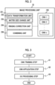
Fig. 2 is a functional block diagram of an image processing unit. -
Fig. 3 is a diagram showing an outline of an image processing procedure. -
Fig. 4 is a diagram showing an example of a structure of a CNN adopted inEmbodiment 1. -
Fig. 5 is a diagram showing training data for the CNN. -
Fig. 6 is a diagram showing a training process of the CNN. -
Fig. 7 is a diagram showing a flow of ringing correction ofEmbodiment 1. -
Fig. 8 is a diagram showing the ringing correction including DC processing. -
Fig. 9 is a diagram showing a flow of ringing correction ofEmbodiment 2. -
Fig. 10 is a diagram showing a relationship between a measurement matrix size and a reconstruction matrix size. -
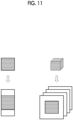
Fig. 11 is a diagram showing the occurrence of Gibbs ringing. -
Fig. 12 is a diagram showing processing of Application Example 1. -
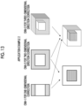
Fig. 13 is a diagram showing a training image set for a CNN in Application Example 2. -
Fig. 14 is a diagram showing image processing of Application Example 2. -
Fig. 15 is a diagram showing ringing correction processing of Application Example 3. -
Fig. 16 is a diagram showing an application example to an elliptical sampling pattern. - Hereinafter, embodiments of an MRI apparatus and an image processing method realized by the MRI apparatus according to an embodiment of the present invention will be described with reference to the accompanying drawings.
- First, an outline of a configuration of an
MRI apparatus 1 to which the present invention is applied will be described. The present invention can be applied to most types of MRI apparatuses that are currently in widespread use, and the configuration thereof roughly includes animaging unit 10 that collects nuclear magnetic resonance signals, acomputer 20 that controls the imaging unit and performs various types of operations, and various devices that are associated with theimaging unit 10 and thecomputer 20, such as an input device, a display device, and an external storage device, as shown inFig. 1 . - Since the configuration of the
imaging unit 10 is the same as a configuration of a normal MRI apparatus, a detailed description thereof will be omitted, but theimaging unit 10 comprises a static magnetic field magnet 11 that generates a static magnetic field space in which asubject 5 is placed, a gradientmagnetic field coil 12 that applies a gradient magnetic field in a static magnetic field, anRF transmission coil 13, an RF receivecoil 14, a gradient magneticfield power supply 15 that drives these coils and atransmitter 16, areceiver 17 to which a high-frequency receive coil is connected, and a bed device 19 that transports thesubject 5 into the static magnetic field space. Further, the imaging unit comprises asequencer 18 that controls the operations of sampling the signals via the gradientmagnetic field coil 12, theRF transmission coil 13, and the RF receivecoil 14 in accordance with a pulse sequence. - The
computer 20 includes animaging controller 21 that controls the operation of theimaging unit 10 via thesequencer 18, animage processing unit 23 that performs image reconstruction and other processing on measurement data (k-space data) collected by theimaging unit 10, and adisplay controller 25 that controls the display of the reconstructed images, a GUI, and the like. - The
computer 20 can be configured as a general-purpose computer comprising a CPU or a GPU and a memory, and the above-described functions of the computer are programmed in advance and realized by uploading the program to the CPU or the like. In addition, some functions of the computer may be realized by hardware such as an ASIC or a programmable IC, and the computer according to the embodiment of the present invention includes these hardware components. - The
image processing unit 23 according to the present embodiment includes animage generation unit 231 and aringing correction unit 234. - The
image generation unit 231 is a functional unit that performs operations such as an inverse Fourier transform using measurement data collected by theimaging unit 10, that is, k-space data, to reconstruct an image, and comprises, as shown inFig. 2 , adata transformation unit 232 that transforms the measurement data (k-space data) into real space data (image data), and a matrixsize change unit 233 that changes a matrix size of the k-space data. - The
ringing correction unit 234 comprises one or a plurality ofCNNs 235 that have been trained to correct Gibbs ringing that has occurred in a reconstructed image, and a combiningunit 236 that combines k-space data of the image after the CNN 235 is applied with the original measurement data to perform processing of maintaining data consistency. - As shown in
Fig. 3 , theimage processing unit 23 having the above-described configuration executes a step (S 1) of training the CNN 235 by using a correct answer image in which the ringing has not occurred or the ringing has occurred to the extent that the ringing can be ignored and an input image (input image for training) reconstructed under a condition in which the ringing has occurred, a step (S2) of applying the trained CNN 235 to the image reconstructed by theimage generation unit 231 to correct the ringing of the image, and a step (S3) of combining the k-space data of the output image of the CNN 235 and the k-space data of the image before input to the CNN 235 by the combiningunit 236. As a result, the measurement data changed by the ringing correction via the CNN is replaced with the original measurement data, allowing the final image, which has undergone the ringing correction while preserving the information of the original measurement data, to be obtained. - Hereinafter, a specific embodiment of processing performed by the
image processing unit 23 will be described. In the following description,Fig. 2 showing a configuration example of theimage processing unit 23 andFig. 3 showing an outline of the processing will be referred to as needed. - In the present embodiment, the ringing correction of an image (two-dimensional image or three-dimensional image) in which the measurement matrix of the measurement data is a rectangular or rectangular parallelepiped shape, the matrix size is expanded in a two-dimensional direction or a three-dimensional direction, and the image is reconstructed is described as an example. In addition, in the drawings referred to, a case in which a two-dimensional image is used as a target is shown for simplicity of the description.
- First, a CNN that has been trained to correct ringing that has occurred in the image is prepared (
Fig. 3 : S1). Since the measurement data obtained by the MRI apparatus is complex data and the image is also a complex image, the CNN is a complex-valued CNN.Fig. 4 shows an example of the complex-valued CNN adopted in the present embodiment. - The
CNN 235 is a complex-valued CNN having a nine-layer structure in which each layer is formed by a block consisting of a convolution layer, an activation function (ReLU), and a pooling layer, the real part and the imaginary part of the input image are combined in the first layer, and the real part and the imaginary part are separated in the ninth layer. A kernel size or the number of channels of each layer is not particularly limited, but for example, the kernel size can be about 3 × 3 to 9 × 9, and the number of channels can be about 16 Ch to 128 Ch. In addition, in the present embodiment, a simple CNN is shown as an example, but the CNN is not limited to this. For example, a resolution-changed CNN, such as U-net, may be used. - The CNN is trained by using a large number of training data sets of training data including an image (correct answer image) acquired under a condition in which Gibbs ringing has not occurred or the Gibbs ringing has occurred to the extent that the Gibbs ringing can be ignored and an image (input image for training) obtained under a condition in which Gibbs ringing has occurred for the same imaging target, and repeating processing of adjusting parameters (weights and biases) of the neural network such that the output image in which a difference between the input image and the correct answer image is minimized is obtained.
- Therefore, first, the correct answer image and the input image for training are prepared as the training data (
Fig. 6 : S11). As the correct answer image, an image reconstructed from the measurement data (two-dimensional or three-dimensional k-space data) captured by three-dimensional measurement at a large measurement matrix size is used. In a case in which the measurement matrix size is equal to or larger than the reconstruction matrix, almost no Gibbs ringing occurs in the reconstructed image. - The input image for training is an image in which the ringing has occurred, and for example, an image reconstructed by performing zero-filling of a high-frequency region on measurement data obtained at a measurement matrix size smaller than the above-described measurement data to change a size of the measurement data to the k-space data having the same matrix size as the k-space data of the correct answer image.
-
Fig. 5 shows an example of the training data used for training the CNN. In this example,correct answer image 500 is subjected to a Fourier transform (FT) to obtain k-space data 501, a low-frequency region of the k-space data 501 is cut out, and the periphery (high-frequency region) ofcutout data 502 is subjected to zero-filling (ZF), and then k-space data 503 after zero-filling is subjected to an inverse Fourier transform (IFT). Animage 504 obtained by this way is used as the input image for training. It should be noted that the example shown inFig. 5 is a representative example of the training data, and the present invention is not limited thereto. - For example, in the present embodiment, as an example, a case is described in which the measurement data of the rectangular sampling pattern is expanded in the two-dimensional direction and the size is changed as described above, but the measurement matrix size of the input image for training, the sampling pattern during measurement, and the expansion direction of the matrix (axial direction in which the size is changed), so that it is also possible to generate the trained CNN corresponding thereto. The modification example of the training data will be described in detail in the embodiments and the application examples described below.
- In the training of the CNN, as shown in
Fig. 6 , the parameters of the CNN are repeatedly adjusted by using the prepared correct answer image and the input image for training until the difference (Loss evaluation function) between the input image after the CNN is applied and the correct answer image is minimized (S12, S14). For each repetition, the input image of the CNN is updated with the output image of the previous repetition. Here, the image for updating the input image may be the output image of the immediately preceding repetition, but as shown by a dotted line inFig. 6 , the output image may be subjected to data consistency processing (hereinafter referred to as DC processing) described later (S13), and the processed image may be used as the input image for the next repetition. In this way, by adding the DC processing in the training process of the CNN, the ringing correction accuracy of the CNN can be improved. - Hereinafter, the ringing correction processing (S2 in
Fig. 3 ) using the trainedCNN 235 and the processing (including the DC processing) (S3 inFig. 3 ) performed by the combiningunit 236 will be described with reference toFigs. 7 and8 . - The
CNN 235 is applied to the image that is the ringing correction target. As shown inFig. 8 , the image to which theCNN 235 is applied is animage 800 in which the measurement data collected by theimaging unit 10 at any measurement matrix size is reconstructed at the reconstruction matrix size different from the measurement matrix size. Specifically, as shown inFig. 8 , the image is animage 803 obtained by expanding the matrix size of themeasurement data 801 of theimage 800 acquired by theimaging unit 10 by performing zero-filling (ZF) of the periphery thereof in accordance with the reconstruction matrix size (S21), and performing an inverse Fourier transform (IFT) on the expanded k-space data 802. The Gibbs ringing has occurred in theimage 803 in the direction in which the matrix size is changed, for example, in the two-dimensional direction in a case of a two-dimensional size change. By inputting the image to the trained CNN, to obtain anoutput image 804 in which the ringing is corrected (S22). - The combining
unit 236 performs the DC processing on theoutput image 804 of theCNN 235. As shown inFig. 8 , in the DC processing, theoutput image 804 is subjected to a Fourier transform to be restored to k-space data 805, aregion 806 corresponding to the measurement matrix size of themeasurement data 801 is set to zero, and theoriginal measurement data 801 is added to theregion 806. That is, the k-space data 805 in which theregion 806 is set to zero and the k-space data 802 after zero-filling are combined to obtain combined k-space data 807. - Finally, the combined k-
space data 807 is subj ected to an inverse Fourier transform (IFT) to obtain a final image 808 (S24). - According to the present embodiment, by performing the DC processing after the CNN is applied, the original measurement data is maintained in the final image, and the high-frequency region is extrapolated, thereby suppressing the ringing.
- In the present embodiment, the two types of processing in
Embodiment 1, that is, the ringing correction processing using theCNN 235 and the DC processing via the combiningunit 236, are repeated two or more times. -
Fig. 9 shows a flow of processing according to the present embodiment. The specific contents of the training process of theCNN 235 and the subsequent processing are the same as the specific contents inEmbodiment 1, and thus the overlapping description is omitted. - In the present embodiment as well, the measurement data of the image, which is the correction target, is expanded the zero-filling to have the desired reconstruction matrix size (S21), and the k-space data after zero-filling is subjected to an inverse Fourier transform to obtain image data, and the
CNN 235 is applied (S22). Next, the combiningunit 236 replaces the low-frequency region of the k-space data of the output image of theCNN 235 with the original measurement data, and combines the k-space data in which the low-frequency region is the original measurement data and the high-frequency region surrounding the low-frequency region is the data after the CNN is applied (S23). After these two types of processing end, the combined k-space data is subjected to an inverse Fourier transform to obtain image data (S24), and the processing is returned to the ringing correction processing using theCNN 235, these types of processing (S22 to S24) are repeated. In a determination of whether or not to end the processing (S25), a predetermined number of repetitions may be set in advance, or the determination may be made by using an evaluation function such as an error function. In addition, in a case in which theCNN 235 consists of a plurality of CNNs having different characteristics and the plurality of CNNs can be applied in multiple stages in accordance with the characteristics of the measurement data, a different CNN may be applied for each repetition. - According to the present embodiment, by repeating the ringing correction processing and the DC processing within a limited range, a ringing correction effect can be further enhanced.
- The present embodiment is characterized in that the ringing correction processing (
Fig. 3 : S2) and the DC processing (Fig. 3 : S3) are the same as those inEmbodiment 1 orEmbodiment 2, and the effect of the DC processing is incorporated in the training of the CNN. - As described in
Embodiment 1, in the training of the CNN, the parameters such as the weights and the biases of the CNN are adjusted while updating the input image, and the training end is determined by using the Loss evaluation function. A known function such as the sum of squares of the difference is used as the Loss evaluation function, but in the present embodiment, the CNN is trained by increasing, in the loss evaluation function, the weight of the error in the measurement matrix region, that is, the matrix region of the actually measured measurement data, to be larger than the weight of the error in other regions. - Specifically, in a case in which the correct answer image (full-sampling image) is denoted by A, the k-space data is denoted by ka, the input image (zero-filled image) is denoted by B, and the k-space data is denoted by kb, in the related art, the weights and the biases of the CNN are trained such that a loss function represented by Equation (1) is minimized.

- On the other hand, in the present embodiment, as shown in Expression (2), a Loss function in which a weight W(kr) (weight at the coordinate kr) is given to the coordinate in the k-space is used, and the weight is varied depending on the region.

- Here, W(kr) is, for example, defined in the following manner.
- W(kr) = 1 in a case in which Kr is within the measurement matrix region.
- W(kr) = 0.5 in a case in which Kr is outside the measurement matrix region.
- It should be noted that the numerical value of the weight is merely an example and is not limited thereto.
- By increasing the weight in the measurement matrix region to be larger than the weight outside the region in this way, the weights and the biases of the CNN are trained such that the signal in the measurement matrix region is not changed, and the outside of the region is extrapolated.
- The method of training the CNN according to the present embodiment is different from the technology described in
JP2021-532875A - In Embodiment 3, as in
Embodiment 1, the DC processing is performed by the combiningunit 236 after the ringing correction using the CNN, but in Embodiment 3, in a case in which the CNN is trained, the training is performed such that the data consistency is maintained, and thus it is also possible to omit the DC processing (S23) after the CNN is applied. - Although the embodiments of the MRI apparatus and the image processing method according to the embodiment of the present invention are described above, in the present invention, it is also possible to perform the training of the CNN in accordance with the measurement conditions, such as the measurement matrix and the sampling pattern of the image that is the ringing correction target. Hereinafter, an embodiment (application example) will be described in which the ringing correction and the DC processing are performed using a plurality of trained CNNs.
- In the present application example, a CNN trained by using training data in which a ratio (reconstruction matrix size/measurement matrix size) of the reconstruction matrix size to the measurement matrix size of the measurement data is a predetermined matrix ratio is used.
- The correct answer image and the input image for training used as the training data are the same as those in
Embodiment 1, but all of a large number of training data sets have the same ratio between the matrix size of the correct answer image and the measurement matrix size of the input image for training. The Gibbs ringing has occurred by the presence of a step between the measurement matrix and the high-frequency region around the measurement matrix region due to zero-filling performed on the periphery of the measurement matrix region of the k-space data, as shown inFig. 10 . In addition, it can be known that the width of the streak of the ringing corresponds to the frequency of the point spread function (PSF) (function shown on the right side ofFig. 10 ) obtained by performing a Fourier transform on a cutout waveform of the measurement data, and depends on the matrix ratio. Therefore, the CNN that has been trained to perform the ringing correction by keeping the matrix ratio constant can obtain a high ringing correction effect at this matrix ratio. - As the matrix ratio of the training data, one or a plurality of representative matrix ratios in the MR image can be adopted. In a case in which the ringing
correction unit 234 comprises a plurality of CNNs trained for each of the plurality of matrix ratios, one or two CNNs closest to the matrix ratio of the image that is the correction target are selected from among the plurality of CNNs and applied. In a case of comprising one CNN that has been trained at a predetermined matrix ratio, it is preferable to perform filter processing in addition to the DC processing after the CNN processing. In a case of performing the filter processing, the DC processing is executed, and then the filter processing is performed. - In a case in which an image having a matrix ratio different from the matrix ratio of the training data of the CNN is processed, large ringing is corrected, but small ringing may remain. By adding the filter processing, such residual ringing can be reduced.
- According to the present application example, by comprising the CNN that has been trained with a fixed matrix ratio, it is possible to obtain a high ringing correction effect for an image in which the matrix ratio is within a specific range.
- In
Embodiment 1, the image expanded in the two-dimensional direction in a case of performing zero-filling on the rectangular measurement data and subjected to an inverse Fourier transform is used as the input image for training the CNN, but it is also possible to train the CNN to obtain a ringing correction effect for the one-dimensional direction by expanding only in the one-dimensional direction instead of the two-dimensional direction. As a result, a trained CNN having a ringing correction effect for the one-dimensional direction is obtained. The same applies to a case of the three-dimensional measurement data, the image obtained by performing an inverse Fourier transform on the k-space data expanded by performing zero-filling in the two-dimensional direction or the one-dimensional direction instead of zero-filling in the three-dimensional direction may be used, and a trained CNN having a ringing correction effect for the expansion direction can be obtained.Fig. 11 shows an example of measurement data obtained by expanding two-dimensional measurement data in a one-dimensional direction and an example of measurement data obtained by expanding three-dimensional measurement data in a two-dimensional direction. - In a case of applying the CNN having such a ringing correction effect for the low-dimensional direction, the ringing correction in accordance with the dimension of the image that is the correction target can be performed by using the CNN in multiple stages. For example, in a case in which the correction target is a two-dimensional image obtained by zero-filling in two directions, as shown in
Fig. 12 , first, the CNN for the one-dimensional direction correction is applied to perform the ringing correction for the direction (S31, S32), and then the DC processing is performed (S33). Next, the image after the ringing correction and the DC processing is rotated such that the expansion direction of the measurement data matches the one-dimensional direction corrected by the CNN (S34, S35), the CNN for the same one-dimensional correction is applied (S32), and then the DC processing is performed (S33). That is, in the present application example,Embodiment 2 is applied, and the two types of processing are repeated, but the rotation of the image (S34) is added between the repetitions. - In a case of the three-dimensional image, the CNN for the one-dimensional correction can be repeatedly used three times while interposing processing of matching the correction direction of the CNN with the expansion direction of the matrix size. Alternatively, it is also possible to use the CNN that has learned a ringing correction effect for the two-dimensional direction, apply the CNN for the two-dimensional direction correction to one surface of the three-dimensional data, and then apply the CNN for the one-dimensional correction for a direction orthogonal to the surface in a sequential manner, or to apply the CNN for the one-dimensional correction for one direction and then apply the CNN for the two-dimensional correction. In this case as well, the DC processing and image the transposition processing are performed after one application of the CNN, which is the same as in a case of the two-dimensional image. That is, as shown in
Fig. 13 , by combining the CNNs for the one-dimensional correction and the two-dimensional correction, it is possible to perform the ringing correction on the image in which the ringing has occurred in more axial directions than the number of axes (the number of directions) learned by the CNN. - According to the present application example, since the CNN for the one-dimensional direction correction or the two-dimensional direction correction need only be trained as the CNN that performs the ringing correction, the burden of the training and the application of the CNN can be reduced, and the same ringing correction effect as in a case of using the CNN trained using an image having the same dimension as the image that is the correction target can be obtained.
- It should be noted that the CNN that corrects the ringing in three directions may be applied once to the three-dimensional image.
- In the present application example, the CNN is trained for each sampling pattern of the measurement data, and the CNN corresponding to the sampling pattern of the correction target image is used. As shown in
Fig. 14 , for the collection of the measurement data in the MRI apparatus, the raster scanning in which the k-space is scanned parallel to the axis thereof and radial scanning in which the k-space is scanned radially with the origin of the k-space as the center are used. The former is a rectangular sampling pattern in a case of the two-dimensional data and a rectangular parallelepiped sampling pattern in a case of the three-dimensional data. The latter is an elliptical sampling pattern in a case of the two-dimensional data and a cylindrical or spherical sampling pattern in a case of the three-dimensional data. - In the present application example, the CNN is trained by using, as the input image for training, the measurement data of these various sampling patterns. For example, in a case of the rectangular sampling pattern, as shown in
Fig. 15 , a low-frequency region that is the measurement region in the k-space data of thecorrect answer image 1510 is cut out with arectangular sampling pattern 1501, the outside thereof is subjected to zero-filling, and the k-space data 1502 is subj ected to an inverse Fourier transform to obtain an input image fortraining 1520. The same applies to other sampling patterns, for example, an input image for training for an elliptical shape, as shown inFig. 16 , can be created by changing the shape of thesampling pattern 1501 to a circular shape. In addition, in a case of expanding the matrix size by zero-filling after the cutout, the expansion in only the one-dimensional direction or the expansion in only the two-dimensional direction for three-dimensional data may be performed as in Application Example 2 described above, to use the low-dimensional input image for training. - The CNN is trained by using the prepared correct answer image and the input image for training. The training process is the same as the training process in
Embodiment 1, and the parameters of the CNN are adjusted until a predetermined Loss function is minimized, as shown inFig. 6 . In the repetition of the training process, the DC processing (Fig. 6 : S13) may be inserted, or the weighting of the Loss function with respect to the error in the measurement matrix region (processing of Embodiment 3) may be performed. - In the application of the CNN, in accordance with the sampling pattern of the image that is the correction target, the CNN of the corresponding sampling pattern is selected, and the ringing correction processing is performed. Then, the DC processing is performed, and the CNN application and the DC processing are repeated as appropriate, which is the same as in
Embodiments 1 to 3. - According to the present application example, by applying the CNN for each sampling pattern of the image, more effective ringing correction can be realized.
- Although the embodiments and the application examples of the present invention are described above, each processing included in the embodiments and the application examples can be combined as long as there is no technical contradiction, known processing such as filtering can be added, and such changes are also included in the present invention.
-
- 1: MRI apparatus
- 10: imaging unit
- 20: computer
- 23: image processing unit
- 231: image generation unit
- 232: data transformation unit
- 233: matrix size change unit
- 234: ringing correction unit
- 235: CNN
- 236: combining unit (DC processing unit)
Claims (13)
- A magnetic resonance imaging apparatus (1) comprising:an imaging unit (10) that collects measurement data consisting of nuclear magnetic resonance signals; and one or more processors than have a function of reconstructing the measurement data at a desired reconstruction matrix size and a function of correcting ringing which occurs in a reconstructed image in a case in which a measurement matrix size of the measurement data and the reconstruction matrix size are different from each other,wherein the one or more processors have one or a plurality of CNNs (235) that have been trained to generate an output image in which the ringing of an input image is corrected, and are configured to generate composite data by replacing a part of k-space data obtained by performing a Fourier transform on the output image of the CNN with the measurement data before the input image of the CNN is reconstructed and generate a ringing-corrected image by performing an inverse Fourier transform on the composite data.
- The magnetic resonance imaging apparatus according to claim 1,
wherein the one or more processors are configured to repeat ringing correction processing via the CNN (235) and combining processing for generating composite data at least twice. - The magnetic resonance imaging apparatus according to claim 1,
wherein the CNN (235) includes a CNN that has been trained by using, as training data, a correct answer image in which the ringing has not occurred and an image obtained by performing an inverse Fourier transform on k-space data in which a size of a measurement matrix region is smaller than a matrix size of the correct answer image. - The magnetic resonance imaging apparatus according to claim 3,
wherein the CNN (235) has been trained by increasing a weight of an error in the measurement matrix region to be larger than a weight of an error in a region other than the measurement matrix region in a loss evaluation function during training. - The magnetic resonance imaging apparatus according to claim 1,
wherein the CNN (235) includes a CNN that has been trained to obtain a ringing correction effect for an input image in which a ratio (matrix ratio) between the measurement matrix size and the reconstruction matrix size is a predetermined value. - The magnetic resonance imaging apparatus according to claim 5,wherein the CNN (235) includes a plurality of CNNs that have been trained to obtain a ringing correction effect for input images having different matrix ratios, andthe one or more processors select at least one of the plurality of CNNs to perform ringing correction.
- The magnetic resonance imaging apparatus according to claim 1,
wherein the CNN (235) includes a CNN that has been trained to obtain a ringing correction effect for at least a one-dimensional direction of the input image. - The magnetic resonance imaging apparatus according to claim 1,wherein the CNN (235) includes a plurality of CNNs that have been trained to obtain a ringing correction effect for input images having different sampling patterns, for each sampling pattern of the measurement data, andthe one or more processors are configured to select at least one of the plurality of CNNs to perform ringing correction.
- A magnetic resonance imaging apparatus (1) comprising:an imaging unit (10) that collects measurement data consisting of nuclear magnetic resonance signals; and one or more processors that have a function of reconstructing the measurement data at a desired reconstruction matrix size and a function of correcting ringing which occurs in a reconstructed image in a case in which a measurement matrix size of the measurement data and the reconstruction matrix size are different from each other,wherein the one or more processors have one or a plurality of CNNs (235) that have been trained to generate an output image in which the ringing of an input image is corrected, and the CNNs include a CNN that has been trained by using, as training data, a correct answer image in which the ringing has not occurred and an image obtained performing an inverse Fourier transform on k-space data in which a size of a measurement matrix region is smaller than a matrix size of the correct answer image, and increasing a weight of an error in the measurement matrix region that to be larger than a weight of an error in a region other than the measurement matrix region in a loss evaluation function during training.
- An image processing method of, in a case in which measurement data consisting of nuclear magnetic resonance signals collected by a magnetic resonance imaging apparatus (10) is reconstructed at a desired reconstruction matrix size, correcting ringing that occurs in a reconstructed image in a case in which a measurement matrix size of the measurement data and the reconstruction matrix size are different from each other, the image processing method comprising:a step of applying one or a plurality of CNNs (235) that have been trained to generate an output image in which the ringing of an input image is corrected, to a correction target image;a step of generating k-space data by performing a Fourier transform on the correction target image before the CNN is applied and a corrected image after the CNN is applied;a step of generating composite k-space data by replacing a part of the k-space data of the corrected image with a measurement matrix region in the k-space data of the correction target image;a step of performing an inverse Fourier transform on the composite k-space data.
- The image processing method according to claim 10,
wherein the step of applying the CNN (235), the step of generating the k-space data, and the step of generating the composite k-space data are repeated two or more times. - The image processing method according to claim 10, further comprising:a step of training the CNN (235) using, as training data, a correct answer image in which the ringing has not occurred and an image obtained by performing an inverse Fourier transform on k-space data in which a size of the measurement matrix region is smaller than a matrix size of the correct answer image,wherein, in the step of training the CNN, a weight of an error in the measurement matrix region is increased in a loss evaluation function during training.
- An image processing method of, in a case in which measurement data consisting of nuclear magnetic resonance signals collected by a magnetic resonance imaging apparatus (1) is reconstructed at a desired reconstruction matrix size, correcting ringing that occurs in a reconstructed image in a case in which a measurement matrix size of the measurement data and the reconstruction matrix size are different from each other, the image processing method comprising:a step of training a CNN (235) to generate an output image in which the ringing of an input image is corrected; anda step of applying the CNN to a correction target image,wherein, in the step of training the CNN, the CNN is trained by using, as training data, a correct answer image in which the ringing has not occurred and an image obtained by performing an inverse Fourier transform on k-space data in which a size of a measurement matrix region is smaller than a matrix size of the correct answer image, and increasing a weight of an error in the measurement matrix region in a loss evaluation function during training.
Applications Claiming Priority (1)
| Application Number | Priority Date | Filing Date | Title |
|---|---|---|---|
| JP2023174423A JP2025064562A (en) | 2023-10-06 | 2023-10-06 | Magnetic resonance imaging apparatus and image processing method |
Publications (3)
| Publication Number | Publication Date |
|---|---|
| EP4535022A2 true EP4535022A2 (en) | 2025-04-09 |
| EP4535022A3 EP4535022A3 (en) | 2025-07-23 |
| EP4535022A8 EP4535022A8 (en) | 2026-01-07 |
Family
ID=93010615
Family Applications (1)
| Application Number | Title | Priority Date | Filing Date |
|---|---|---|---|
| EP24204540.9A Pending EP4535022A3 (en) | 2023-10-06 | 2024-10-03 | Magnetic resonance imaging apparatus and image processing method |
Country Status (3)
| Country | Link |
|---|---|
| US (1) | US20250114009A1 (en) |
| EP (1) | EP4535022A3 (en) |
| JP (1) | JP2025064562A (en) |
Citations (1)
| Publication number | Priority date | Publication date | Assignee | Title |
|---|---|---|---|---|
| JP2021532875A (en) | 2018-07-30 | 2021-12-02 | ハイパーファイン,インコーポレイテッド | Deep learning technology for magnetic resonance image reconstruction |
Family Cites Families (4)
| Publication number | Priority date | Publication date | Assignee | Title |
|---|---|---|---|---|
| WO2013047275A1 (en) * | 2011-09-29 | 2013-04-04 | 株式会社 日立メディコ | Magnetic resonance imaging device and magnetic resonance imaging method |
| WO2017206048A1 (en) * | 2016-05-31 | 2017-12-07 | Shanghai United Imaging Healthcare Co., Ltd. | System and method for removing gibbs artifact in medical imaging system |
| CN113557526B (en) * | 2018-08-15 | 2025-11-14 | 海珀菲纳股份有限公司 | Magnetic resonance imaging methods, systems, and computer program products |
| JP2024036308A (en) * | 2022-09-05 | 2024-03-15 | キヤノンメディカルシステムズ株式会社 | Image processing device, image processing method, and magnetic resonance imaging device |
-
2023
- 2023-10-06 JP JP2023174423A patent/JP2025064562A/en active Pending
-
2024
- 2024-10-03 EP EP24204540.9A patent/EP4535022A3/en active Pending
- 2024-10-04 US US18/907,439 patent/US20250114009A1/en active Pending
Patent Citations (1)
| Publication number | Priority date | Publication date | Assignee | Title |
|---|---|---|---|---|
| JP2021532875A (en) | 2018-07-30 | 2021-12-02 | ハイパーファイン,インコーポレイテッド | Deep learning technology for magnetic resonance image reconstruction |
Non-Patent Citations (1)
| Title |
|---|
| QIANQIAN ZHANG ET AL., MAGN RESON MED, vol. 82, 2019, pages 2133 - 2145 |
Also Published As
| Publication number | Publication date |
|---|---|
| EP4535022A3 (en) | 2025-07-23 |
| US20250114009A1 (en) | 2025-04-10 |
| EP4535022A8 (en) | 2026-01-07 |
| JP2025064562A (en) | 2025-04-17 |
Similar Documents
| Publication | Publication Date | Title |
|---|---|---|
| US10692250B2 (en) | Generalized multi-channel MRI reconstruction using deep neural networks | |
| US11696700B2 (en) | System and method for correcting for patient motion during MR scanning | |
| US11941732B2 (en) | Multi-slice MRI data processing using deep learning techniques | |
| US9196062B2 (en) | Method and apparatus for generating magnetic resonance image | |
| US9606207B2 (en) | Method and apparatus for generating magnetic resonance image | |
| US11914015B2 (en) | Magnetic resonance imaging apparatus and image processing method | |
| CN115113114B (en) | Systems and methods for deep learning-based accelerated magnetic resonance imaging with extended field-of-view coil sensitivity calibration | |
| US12130347B2 (en) | Magnetic resonance imaging apparatus, image processing apparatus, and image processing method | |
| KR102233996B1 (en) | Device and method for reconstructing magnetic resonance image thereof | |
| KR102769810B1 (en) | Magnetic resonance image processing apparatus and method using artificial neural network in k-space domain | |
| KR102584166B1 (en) | MAGNETIC RESONANCE IMAGE PROCESSING APPARATUS AND METHOD USING ARTIFICIAL NEURAL NETWORK AND RESCAlING | |
| CN112927313B (en) | Magnetic resonance image reconstruction method, device, computer equipment and readable storage medium | |
| CN119986501A (en) | Systems and methods for reducing scan time of PROPELLER magnetic resonance imaging acquisitions using deep learning reconstruction | |
| US20250114009A1 (en) | Magnetic resonance imaging apparatus and image processing method | |
| US12601806B2 (en) | Imaging device of eliminating electromagnetic interference of magnetic resonance and imaging method thereof | |
| US20250117987A1 (en) | Magnetic resonance imaging apparatus and image processing method | |
| Riek et al. | Out-of-plane motion compensation in multislice spin-echo MRI | |
| EP4365618A1 (en) | Multilayer perceptron for machine-learning image reconstruction | |
| US20250116741A1 (en) | Magnetic resonance imaging apparatus and image processing method | |
| US20250117988A1 (en) | Magnetic resonance imaging apparatus and image processing method | |
| KR101826961B1 (en) | Method and system for magnetic resonance imaging using compressive sensing | |
| JP7183048B2 (en) | MAGNETIC RESONANCE IMAGING SYSTEM, MAGNETIC RESONANCE IMAGING METHOD AND MAGNETIC RESONANCE IMAGING PROGRAM | |
| KR102894500B1 (en) | Method for obtaining magnetic resonance images using an artificial neural network model and method for controlling the program | |
| US20260112094A1 (en) | Image quality improvement in magnetic resonance imaging using machine learning reconstruction | |
| CN113093076B (en) | Magnetic resonance image processing method and device and electronic equipment |
Legal Events
| Date | Code | Title | Description |
|---|---|---|---|
| PUAI | Public reference made under article 153(3) epc to a published international application that has entered the european phase |
Free format text: ORIGINAL CODE: 0009012 |
|
| STAA | Information on the status of an ep patent application or granted ep patent |
Free format text: STATUS: THE APPLICATION HAS BEEN PUBLISHED |
|
| AK | Designated contracting states |
Kind code of ref document: A2 Designated state(s): AL AT BE BG CH CY CZ DE DK EE ES FI FR GB GR HR HU IE IS IT LI LT LU LV MC ME MK MT NL NO PL PT RO RS SE SI SK SM TR |
|
| PUAL | Search report despatched |
Free format text: ORIGINAL CODE: 0009013 |
|
| AK | Designated contracting states |
Kind code of ref document: A3 Designated state(s): AL AT BE BG CH CY CZ DE DK EE ES FI FR GB GR HR HU IE IS IT LI LT LU LV MC ME MK MT NL NO PL PT RO RS SE SI SK SM TR |
|
| RIC1 | Information provided on ipc code assigned before grant |
Ipc: G01R 33/56 20060101AFI20250618BHEP Ipc: G01R 33/565 20060101ALI20250618BHEP Ipc: G06N 3/045 20230101ALI20250618BHEP |
|
| RAP3 | Party data changed (applicant data changed or rights of an application transferred) |
Owner name: FUJIFILM CORPORATION |
|
| STAA | Information on the status of an ep patent application or granted ep patent |
Free format text: STATUS: REQUEST FOR EXAMINATION WAS MADE |
|
| 17P | Request for examination filed |
Effective date: 20260108 |