EP4535020A1 - Wiring unit - Google Patents
Wiring unit Download PDFInfo
- Publication number
- EP4535020A1 EP4535020A1 EP23815238.3A EP23815238A EP4535020A1 EP 4535020 A1 EP4535020 A1 EP 4535020A1 EP 23815238 A EP23815238 A EP 23815238A EP 4535020 A1 EP4535020 A1 EP 4535020A1
- Authority
- EP
- European Patent Office
- Prior art keywords
- terminal
- main body
- bent plate
- protector
- wiring unit
- Prior art date
- Legal status (The legal status is an assumption and is not a legal conclusion. Google has not performed a legal analysis and makes no representation as to the accuracy of the status listed.)
- Pending
Links
Images











Classifications
-
- H—ELECTRICITY
- H01—ELECTRIC ELEMENTS
- H01M—PROCESSES OR MEANS, e.g. BATTERIES, FOR THE DIRECT CONVERSION OF CHEMICAL ENERGY INTO ELECTRICAL ENERGY
- H01M50/00—Constructional details or processes of manufacture of the non-active parts of electrochemical cells other than fuel cells, e.g. hybrid cells
- H01M50/50—Current conducting connections for cells or batteries
- H01M50/502—Interconnectors for connecting terminals of adjacent batteries; Interconnectors for connecting cells outside a battery casing
- H01M50/503—Interconnectors for connecting terminals of adjacent batteries; Interconnectors for connecting cells outside a battery casing characterised by the shape of the interconnectors
-
- H—ELECTRICITY
- H01—ELECTRIC ELEMENTS
- H01M—PROCESSES OR MEANS, e.g. BATTERIES, FOR THE DIRECT CONVERSION OF CHEMICAL ENERGY INTO ELECTRICAL ENERGY
- H01M50/00—Constructional details or processes of manufacture of the non-active parts of electrochemical cells other than fuel cells, e.g. hybrid cells
- H01M50/20—Mountings; Secondary casings or frames; Racks, modules or packs; Suspension devices; Shock absorbers; Transport or carrying devices; Holders
- H01M50/204—Racks, modules or packs for multiple batteries or multiple cells
- H01M50/207—Racks, modules or packs for multiple batteries or multiple cells characterised by their shape
- H01M50/211—Racks, modules or packs for multiple batteries or multiple cells characterised by their shape adapted for pouch cells
-
- H—ELECTRICITY
- H01—ELECTRIC ELEMENTS
- H01M—PROCESSES OR MEANS, e.g. BATTERIES, FOR THE DIRECT CONVERSION OF CHEMICAL ENERGY INTO ELECTRICAL ENERGY
- H01M50/00—Constructional details or processes of manufacture of the non-active parts of electrochemical cells other than fuel cells, e.g. hybrid cells
- H01M50/20—Mountings; Secondary casings or frames; Racks, modules or packs; Suspension devices; Shock absorbers; Transport or carrying devices; Holders
- H01M50/204—Racks, modules or packs for multiple batteries or multiple cells
- H01M50/207—Racks, modules or packs for multiple batteries or multiple cells characterised by their shape
- H01M50/209—Racks, modules or packs for multiple batteries or multiple cells characterised by their shape adapted for prismatic or rectangular cells
-
- H—ELECTRICITY
- H01—ELECTRIC ELEMENTS
- H01M—PROCESSES OR MEANS, e.g. BATTERIES, FOR THE DIRECT CONVERSION OF CHEMICAL ENERGY INTO ELECTRICAL ENERGY
- H01M50/00—Constructional details or processes of manufacture of the non-active parts of electrochemical cells other than fuel cells, e.g. hybrid cells
- H01M50/20—Mountings; Secondary casings or frames; Racks, modules or packs; Suspension devices; Shock absorbers; Transport or carrying devices; Holders
- H01M50/249—Mountings; Secondary casings or frames; Racks, modules or packs; Suspension devices; Shock absorbers; Transport or carrying devices; Holders specially adapted for aircraft or vehicles, e.g. cars or trains
-
- H—ELECTRICITY
- H01—ELECTRIC ELEMENTS
- H01M—PROCESSES OR MEANS, e.g. BATTERIES, FOR THE DIRECT CONVERSION OF CHEMICAL ENERGY INTO ELECTRICAL ENERGY
- H01M50/00—Constructional details or processes of manufacture of the non-active parts of electrochemical cells other than fuel cells, e.g. hybrid cells
- H01M50/20—Mountings; Secondary casings or frames; Racks, modules or packs; Suspension devices; Shock absorbers; Transport or carrying devices; Holders
- H01M50/298—Mountings; Secondary casings or frames; Racks, modules or packs; Suspension devices; Shock absorbers; Transport or carrying devices; Holders characterised by the wiring of battery packs
-
- H—ELECTRICITY
- H01—ELECTRIC ELEMENTS
- H01M—PROCESSES OR MEANS, e.g. BATTERIES, FOR THE DIRECT CONVERSION OF CHEMICAL ENERGY INTO ELECTRICAL ENERGY
- H01M50/00—Constructional details or processes of manufacture of the non-active parts of electrochemical cells other than fuel cells, e.g. hybrid cells
- H01M50/50—Current conducting connections for cells or batteries
- H01M50/502—Interconnectors for connecting terminals of adjacent batteries; Interconnectors for connecting cells outside a battery casing
- H01M50/507—Interconnectors for connecting terminals of adjacent batteries; Interconnectors for connecting cells outside a battery casing comprising an arrangement of two or more busbars within a container structure, e.g. busbar modules
-
- H—ELECTRICITY
- H01—ELECTRIC ELEMENTS
- H01M—PROCESSES OR MEANS, e.g. BATTERIES, FOR THE DIRECT CONVERSION OF CHEMICAL ENERGY INTO ELECTRICAL ENERGY
- H01M50/00—Constructional details or processes of manufacture of the non-active parts of electrochemical cells other than fuel cells, e.g. hybrid cells
- H01M50/50—Current conducting connections for cells or batteries
- H01M50/502—Interconnectors for connecting terminals of adjacent batteries; Interconnectors for connecting cells outside a battery casing
- H01M50/514—Methods for interconnecting adjacent batteries or cells
-
- H—ELECTRICITY
- H01—ELECTRIC ELEMENTS
- H01M—PROCESSES OR MEANS, e.g. BATTERIES, FOR THE DIRECT CONVERSION OF CHEMICAL ENERGY INTO ELECTRICAL ENERGY
- H01M50/00—Constructional details or processes of manufacture of the non-active parts of electrochemical cells other than fuel cells, e.g. hybrid cells
- H01M50/50—Current conducting connections for cells or batteries
- H01M50/528—Fixed electrical connections, i.e. not intended for disconnection
-
- H—ELECTRICITY
- H01—ELECTRIC ELEMENTS
- H01M—PROCESSES OR MEANS, e.g. BATTERIES, FOR THE DIRECT CONVERSION OF CHEMICAL ENERGY INTO ELECTRICAL ENERGY
- H01M50/00—Constructional details or processes of manufacture of the non-active parts of electrochemical cells other than fuel cells, e.g. hybrid cells
- H01M50/50—Current conducting connections for cells or batteries
- H01M50/543—Terminals
- H01M50/547—Terminals characterised by the disposition of the terminals on the cells
- H01M50/55—Terminals characterised by the disposition of the terminals on the cells on the same side of the cell
-
- H—ELECTRICITY
- H01—ELECTRIC ELEMENTS
- H01M—PROCESSES OR MEANS, e.g. BATTERIES, FOR THE DIRECT CONVERSION OF CHEMICAL ENERGY INTO ELECTRICAL ENERGY
- H01M50/00—Constructional details or processes of manufacture of the non-active parts of electrochemical cells other than fuel cells, e.g. hybrid cells
- H01M50/50—Current conducting connections for cells or batteries
- H01M50/543—Terminals
- H01M50/552—Terminals characterised by their shape
- H01M50/553—Terminals adapted for prismatic, pouch or rectangular cells
-
- H—ELECTRICITY
- H01—ELECTRIC ELEMENTS
- H01M—PROCESSES OR MEANS, e.g. BATTERIES, FOR THE DIRECT CONVERSION OF CHEMICAL ENERGY INTO ELECTRICAL ENERGY
- H01M50/00—Constructional details or processes of manufacture of the non-active parts of electrochemical cells other than fuel cells, e.g. hybrid cells
- H01M50/50—Current conducting connections for cells or batteries
- H01M50/569—Constructional details of current conducting connections for detecting conditions inside cells or batteries, e.g. details of voltage sensing terminals
-
- H—ELECTRICITY
- H01—ELECTRIC ELEMENTS
- H01M—PROCESSES OR MEANS, e.g. BATTERIES, FOR THE DIRECT CONVERSION OF CHEMICAL ENERGY INTO ELECTRICAL ENERGY
- H01M50/00—Constructional details or processes of manufacture of the non-active parts of electrochemical cells other than fuel cells, e.g. hybrid cells
- H01M50/50—Current conducting connections for cells or batteries
- H01M50/572—Means for preventing undesired use or discharge
- H01M50/584—Means for preventing undesired use or discharge for preventing incorrect connections inside or outside the batteries
- H01M50/588—Means for preventing undesired use or discharge for preventing incorrect connections inside or outside the batteries outside the batteries, e.g. incorrect connections of terminals or busbars
-
- H—ELECTRICITY
- H01—ELECTRIC ELEMENTS
- H01M—PROCESSES OR MEANS, e.g. BATTERIES, FOR THE DIRECT CONVERSION OF CHEMICAL ENERGY INTO ELECTRICAL ENERGY
- H01M2220/00—Batteries for particular applications
- H01M2220/20—Batteries in motive systems, e.g. vehicle, ship, plane
-
- Y—GENERAL TAGGING OF NEW TECHNOLOGICAL DEVELOPMENTS; GENERAL TAGGING OF CROSS-SECTIONAL TECHNOLOGIES SPANNING OVER SEVERAL SECTIONS OF THE IPC; TECHNICAL SUBJECTS COVERED BY FORMER USPC CROSS-REFERENCE ART COLLECTIONS [XRACs] AND DIGESTS
- Y02—TECHNOLOGIES OR APPLICATIONS FOR MITIGATION OR ADAPTATION AGAINST CLIMATE CHANGE
- Y02E—REDUCTION OF GREENHOUSE GAS [GHG] EMISSIONS, RELATED TO ENERGY GENERATION, TRANSMISSION OR DISTRIBUTION
- Y02E60/00—Enabling technologies; Technologies with a potential or indirect contribution to GHG emissions mitigation
- Y02E60/10—Energy storage using batteries
Definitions
- a battery module recorded in Patent Document 1 comprises: a plurality of cell components that are stacked in a left-right direction, the cell component including electrode leads at front and rear ends thereof; a module housing that is configured to accommodate the cell components in an internal space formed by four side walls, i.e., upper, lower, left and right side walls; and an end frame that is assembled in front of and behind the cell components, so that the cell components are connected to external devices.
- the joining portion 13 connects the two laminated batteries 11, which are connected in parallel, in series.
- the battery stack 11L includes four joining portions 13 at the front part.
- the battery stack 11L also includes four jointing portions 13 at the rear part.
- the process of forming the joining portion 13 includes bending processing, laser welding, or the like of the electrode leads 12, so the tolerance of the joining portion 13 (and the connecting electrode lead 12A), especially in the front-rear direction, easily becomes large.
- the tolerance of the joining portion 13 (and the connecting electrode lead 12A) in the front-rear direction is about ⁇ several millimeters, which is about five times the thickness of the electrode lead 12.
- the front left end of the battery stack 11L includes an output portion 14.
- the rear right end of the battery stack 11L also includes an output portion 14.
- the output portion 14 is formed by joining two electrode leads 12 that do not form the joining portion 13 among the electrode leads 12.
- the electrode leads 12 forming the output portion 14 are set as output electrode leads 12B.
- the two output electrode leads 12B forming one output portion 14 have polarities the same as each other.
- the output portion 14 forms an overall positive electrode or negative electrode of the battery stack 11L. That is, for example, when the front output portion 14 is the overall positive electrode of the battery stack 11L, the rear output portion 14 is the overall negative electrode of the battery stack 11L.
- An opening portion 36 that penetrates the bent plate portion 33 is formed at the bent plate portion 33 in the up-down direction.
- the opening portion 36 is arranged at the center part of the bent plate portion 33 in the left-right direction.
- the edge portion on the rear side is provided as a locking receiving portion 36A.
- the locking receiving portion 36A can be locked to a locking portion 65A of a flexible piece 62 described later.
- the opening portion 36 has an expanded opening portion 36B that expands to the side of the main body portion 31.
- the terminal accommodating portion 54 is formed to be recessed rearwards from the protector main body 51.
- the terminal accommodating portion 54 includes a main body portion accommodating portion 55, a recess 56, and a wire connecting portion accommodating portion 57.
- the main body portion accommodating portion 55 is arranged at a lower side part of the terminal accommodating portion 54.
- the main body portion accommodating portion 55 has: a bottom wall portion 55A; a left wall portion 55B that extends forwards from the left end of the bottom wall portion 55A; and a communicating hole 55C that opens rightwards.
- the communicating hole 55C communicates with the connecting electrode accommodating recess 52A.
- the main body portion accommodating portion 55 accommodates the main body portion 31 of the terminal 30. As shown in FIG.
- the front surface of the bottom wall portion 55A serves as an abutment portion 58 that abuts against the terminal 30 from behind.
- a part of the main body portion 31 on the side of the connecting portion 32 is arranged in the communicating hole 55C, and the connecting portion 32 is arranged inside the connecting electrode accommodating recess 52A.
- an inner wall 59 that forms the recess 56 includes: a first inner wall 59A and a second inner wall 59B that are opposite to each other in the up-down direction; and two side walls 59C that are opposite to each other in the left-right direction.
- the first inner wall 59A is arranged above the second inner wall 59B (the side of the main body portion accommodating portion 55).
- the bent plate portion 33 of the terminal 30 is arranged inside the recess 56 of the terminal accommodating portion 54, so that the terminal 30 is movable relative to the protector 50 in the front-rear direction.
- the terminal 30 is movable relative to the protector main body 51 between a first position (with reference to FIG. 6 ) and a second position (with reference to FIG. 7 ) in the front-rear direction.
- the first position is the rearmost position to which the terminal 30 is movable
- the second position is the frontmost position to which the terminal 30 is movable.
- FIG. 6 when the terminal 30 is arranged in a state where it is in the first position, the rear surface of the main body portion 31 abuts against the abutment portion 58.
- the terminal 30 moves in the front-rear direction to match the connecting electrode lead 12A.
- the state in which the connecting portion 32 and the connecting electrode lead 12A are in close contact with each other can be ensured, so that the laser welding of the connecting portion 32 and the connecting electrode lead 12A is well performed.
- the wiring unit 20 involved in Embodiment 1 is mounted on a battery stack 11L, which is formed by stacking a plurality of laminated batteries 11 including electrode leads 12, and includes a joining portion 13 for joining the electrode leads 12 of the laminated batteries 11 in a mutually overlapping manner, the wiring unit 20 comprising: a terminal 30; an electric wire 45 that is connected to the terminal 30; and a protector 50 that holds the terminal 30 and the electric wire 45, the terminal 30 including: a main body portion 31; a connecting portion 32 that is configured to extend from the main body portion 31 and is oppositely connected, in a first direction (front-rear direction), to the electrode leads 12 forming the joining portion 13; and at least one bent plate portion 33 that extends from the main body portion 31 to the side of the laminated batteries 11 (rear side) in the first direction, and the protector 50 including: a protector main body 51; and at least one recess 56 that is recessed towards the side of the laminated batteries 11 in the first direction
- the bent plate portion 33 is inserted into the recess 56 so as to be movable in the first direction, so that the connecting portion 32 is moveable relative to the protector 50 in the first direction, so when the connecting portion 32 is connected to the electrode leads 12 forming the joining portion 13, the connecting portion 32 can be brought into contact with the electrode leads 12 even if there is the manufacturing tolerance of the electrode leads 12 in the first direction.
- the reliability of the electrical connection between the connecting portion 32 and the electrode leads 12 can be improved.
- the protector 50 includes the locking portion 65A, and is locked to the terminal 30 from a side (front side) opposite to the side of the laminated batteries 11 in the first direction.
- the movement of the terminal 30 towards the side opposite to the side of the laminated batteries 11 in the first direction can be restricted by means of the locking portion 65A.
- the electric wire 45 is arranged to be closer to the side of the laminated batteries 11 in the first direction than the base 34A, the size by which protrusion from the main body portion 31 of the wire connecting portion 34 to the side opposite to the side of the laminated batteries 11 in the first direction is made is easily reduced.
- the size of the wiring unit 20 in the first direction can be reduced.
- the two bent plate portions 33 are arranged to extend in the same direction as the main body portion 31 of the terminal 130, that is, in the front-rear direction in which the terminal 130 is movable.
- the two bent plate portions 33 may also be arranged on the lower side and the left side of the main body portion 31.
- the two bent plate portions 33 may also be arranged on the lower side and the upper side of the main body portion 31 so as to be opposite to each other.
- the protector 50 has the recesses 56 in positions corresponding to the two bent plate portions 33. That is, two recesses 56 are formed for one terminal 130 in the protector 50.
- the terminal 130 includes a plurality of (two) bent plate portions 33.
- the strength of the bent portion 35 can be improved by means of the folded portion 237.
- the terminal 330 includes the bent portion 35 that connects the end edge of the main body portion 31 and the end edge of the bent plate portion 33, and the plate thickness direction of the bent portion 35 continuously changes from a first direction (front-rear direction) to a direction orthogonal to the first direction (up-down direction) from the main body portion 31 to the bent plate portion 33, and the bent portion 35 includes the protruding portion 337 that protrudes from the bent portion 35 in the plate thickness direction of the bent portion 35.
- the strength of the bent portion 35 can be improved by means of the protruding portion 337.
- two protruding strip portions 438 are formed at the left end and the right end of the bent plate portion 33.
- the protruding strip portion 438 is formed in an elongated shape in the front-rear direction and protrudes downwards from the lower surface of the bent plate portion 33.
- the front end of the protruding strip portion 438 is continuous with the lower end of the protruding portion 437.
- the protruding portion 437 and the protruding strip portion 438 of Embodiment 5 are formed by reinforcement processing.
- the protruding portion 437 and the protruding strip portion 438 also contribute to the improvement of the strength of the bent portion 35 like the protruding portion 337 of Embodiment 4.
- the electrode lead 12 by connecting the electrode lead 12 to the end of the laminated battery 11, when the laminated battery 11 expands and deforms, the electrode lead 12 will also be displaced to a certain extent along with the cell, but in the embodiment, the arc-shaped connecting portion 32A is provided on the connecting portion 32 of the terminal 30, so that the arc-shaped connecting portion 32A can absorb the displacement of the electrode leads 12 to thereby avoid the risk of the structure of the terminal 30 being unstable, and the terminal 30 falling off or even breaking caused by the terminal 30 being pulled when the electrode leads 12 are displaced.
- a convex portion 56A is convexly provided on the side wall of the recess 56, and the convex portion 56A abuts against the flat sheet-shaped bent plate portion 33, which reduces the contact area between the recess 56 and the bent plate portion 33 and facilitates the movement of the bent plate portion 33 in the recess 56.
- the protector main body 50 is provided with a limiting column 66, the terminal 30 is provided with a through hole 37, and the limiting column 66 is configured to pass through the through hole 37.
Landscapes
- Chemical & Material Sciences (AREA)
- Chemical Kinetics & Catalysis (AREA)
- Electrochemistry (AREA)
- General Chemical & Material Sciences (AREA)
- Engineering & Computer Science (AREA)
- Aviation & Aerospace Engineering (AREA)
- Connection Of Batteries Or Terminals (AREA)
Abstract
Description
- The disclosures relate to a wiring unit.
- A high-voltage battery pack, which is used in an electric vehicle, a hybrid vehicle, or the like, generally has a plurality of stacked battery cells that are electrically connected in series or in parallel by means of a wiring unit. As such wiring unit, a wiring unit described in
Japanese Patent Publication No. 2020-527848 Patent Document 1 comprises: a plurality of cell components that are stacked in a left-right direction, the cell component including electrode leads at front and rear ends thereof; a module housing that is configured to accommodate the cell components in an internal space formed by four side walls, i.e., upper, lower, left and right side walls; and an end frame that is assembled in front of and behind the cell components, so that the cell components are connected to external devices. - Patent Document 1:
Japanese Patent Publication No. 2020-527848 - In the aforesaid configuration, a cell component has a part that allows electrode leads of adjacent battery cells to be close to each other so as to be bent, overlap and be electrically connected, and due to the presence of the part, it is not required to provide a bus bar that connects the electrode leads to each other, so that the electrode leads are electrically connected to module terminals that are provided on an end frame. However, due to the bending processing of the electrode leads and the welding of the electrode leads, a comparatively large manufacturing tolerance is easily produced in the part where the electrode leads are connected to each other, especially in a front-rear direction.
- In the aforesaid configuration, when the electrode leads and the module terminals are connected by laser welding or the like, due to the comparatively large manufacturing tolerance of the electrode leads in the front-rear direction, sometimes the module terminals cannot be made to come into full contact with the electrode leads. In such state where the module terminals do not come into full contact with the electrode leads, the electrical connection between the electrode leads and the module terminals may be rendered poor.
- The wiring unit according to the disclosure is mounted on a battery stack, which is formed by stacking a plurality of laminated batteries including electrode leads, and includes a joining portion for joining the electrode leads of the laminated batteries in a mutually overlapping manner, the wiring unit comprising: a terminal; an electric wire that is connected to the terminal; and a protector that holds the terminal and the electric wire, the terminal including: a main body portion; a connecting portion that is configured to extend from the main body portion and is oppositely connected, in a first direction, to the electrode leads forming the joining portion; and at least one bent plate portion that extends from the main body portion to the side of the laminated batteries in the first direction, and the protector including: a protector main body; and at least one recess that is recessed towards the side of the laminated batteries in the first direction relative to the protector main body and accommodates the bent plate portion, the bent plate portion being inserted into the recess so as to be movable in the first direction, so that the connecting portion can come into contact with the electrode leads.
- According to contents of the disclosure, a wiring unit having excellent reliability of electrical connection between a terminal and electrode leads can be provided.
-
-
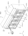
FIG. 1 is a perspective view showing a front part of a power storage module involved inEmbodiment 1. -
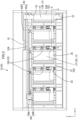
FIG. 2 is a front view of the power storage module. -
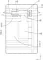
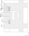
FIG. 3 is an enlarged view showing a periphery of a terminal inFIG. 2 . -
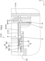
FIG. 4 is a cross-sectional view taken along line A-A inFIG. 2 . -
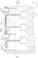
FIG. 5 is a cross-sectional view taken along line B-B inFIG. 3 . -
FIG. 6 is a view showing a first position of a terminal in the B-B cross section inFIG. 3 . -
FIG. 7 is a view showing a second position of the terminal in the B-B cross section inFIG. 3 . -
FIG. 8 is a view with the terminal omitted in the B-B cross section inFIG. 3 . -
FIG. 9 is a cross-sectional view taken along line C-C inFIG. 3 . -
FIG. 10 is a cross-sectional view taken along line D-D inFIG. 5 . -
FIG. 11 is a perspective view showing a periphery of a terminal accommodating portion in the power storage module. -
FIG. 12 is a view with the terminal omitted inFIG. 11 . -
FIG. 13 is a perspective view of a front part of a battery stack. -
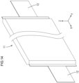
FIG. 14 is a perspective view showing a main part of a laminated battery. -
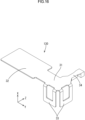
FIG. 15 is a perspective view of a terminal for connecting an electric wire. -
FIG. 16 is a perspective view showing an example of a terminal involved in Embodiment 2. -
FIG. 17 is a perspective view showing an example of the terminal involved in Embodiment 2 different from that inFIG. 16 . -
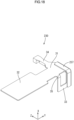
FIG. 18 is a perspective view of a terminal involved in Embodiment 3. -
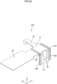
FIG. 19 is a perspective view of a terminal involved in Embodiment 4. -
FIG. 20 is a perspective view of a terminal involved in Embodiment 5. -
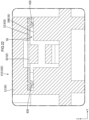
FIG. 21 is a cross-sectional view of a power storage module, and is a view showing a cross section corresponding toFIG. 9 ofEmbodiment 1. -
FIG. 22 is a cross-sectional view of a power storage module, and is a view showing a cross section corresponding toFIG. 10 ofEmbodiment 1. -
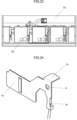
FIG. 23 is a front view of a front part of a power storage module involved in Embodiment 6. -
FIG. 24 is a perspective view of a terminal involved in Embodiment 6. -
FIG. 25 is a perspective view of a protector main body in Embodiment 6 and other embodiments (6)-(7). -
FIG. 26 is an enlarged view of a region D inFIG. 25 . -
FIG. 27 is a perspective view of a terminal involved inEmbodiment 7. - First, embodiments of the disclosure are described by way of examples.
- (1) The wiring unit according to the disclosure is mounted on a battery stack, which is formed by stacking a plurality of laminated batteries including electrode leads, and includes a joining portion for joining the electrode leads of the laminated batteries in a mutually overlapping manner, the wiring unit comprising: a terminal; an electric wire that is connected to the terminal; and a protector that holds the terminal and the electric wire, the terminal including: a main body portion; a connecting portion that is configured to extend from the main body portion and is oppositely connected, in a first direction, to the electrode leads forming the joining portion; and at least one bent plate portion that extends from the main body portion to the side of the laminated batteries in the first direction, and the protector including: a protector main body; and at least one recess that is recessed towards the side of the laminated batteries in the first direction relative to the protector main body and accommodates the bent plate portion, the bent plate portion being inserted into the recess so as to be movable in the first direction, so that the connecting portion can come into contact with the electrode leads.
According to such configuration, the bent plate portion is inserted into the recess so as to be movable in the first direction, so that the connecting portion is moveable relative to the protector in the first direction, so when the connecting portion is connected to the electrode leads forming the joining portion, the connecting portion can be brought into contact with the electrode leads even if there is the manufacturing tolerance of the electrode leads in the first direction. Thus, the reliability of the electrical connection between the connecting portion and the electrode leads can be improved. - (2) Preferably, the terminal includes: a bent portion that connects an end edge of the main body portion to an end edge of the bent plate portion; and a folded portion that is connected to and overlaps the main body portion, the bent portion, and the bent plate portion.
According to such configuration, the strength of the bent portion can be improved by means of the folded portion. - (3) Preferably, the terminal includes a bent portion that connects the end edge of the main body portion and the end edge of the bent plate portion, the plate thickness direction of the bent portion continuously changes from the first direction to a direction orthogonal to the first direction from the main body portion towards the bent plate portion, and the bent portion includes a protruding portion that protrudes from the bent portion in the plate thickness direction of the bent portion.
According to such configuration, the strength of the bent portion can be improved by means of the protruding portion. - (4) Preferably, the bent plate portion includes a protruding strip portion that protrudes from the bent plate portion towards the inner wall of the recess in a direction orthogonal to the first direction and extends in the first direction, and the protruding strip portion and the protruding portion are continuously formed.
According to such configuration, the part where the bent plate portion and the inner wall of the recess come into contact with each other can be reduced by forming the protruding strip portion, so even if the bent plate portion comes into contact with the inner wall of the recess, the bent plate portion becomes easily slidable. In addition, since the protruding strip portion and the protruding portion are continuously formed, the protruding strip portion and the protruding portion are easily formed. - (5) Preferably, a convex portion is convexly provided on the side wall of the recess, and the convex portion abuts against the bent plate portion.
According to such configuration, the contact area between the recess and the bent plate portion is reduced by convexly providing the convex portion on the side wall of the recess, which makes it more convenient for the bent plate portion to slide inside the recess than the case where the entire plane of the bent plate portion comes into contact with the recess. - (6) Preferably, the terminal includes a plurality of bent plate portions.
According to such configuration, the state of the terminal is easily controlled by forming the plurality of bent plate portions. - (7) Preferably, the protector includes an abutment portion that abuts against the terminal from the side of the laminated batteries in the first direction.
According to such configuration, the movement of the terminal towards the side of the laminated batteries in the first direction can be restricted by means of the abutment portion. - (8) Preferably, the protector includes a locking portion that is locked to the terminal from a side opposite to the side of the laminated batteries in the first direction.
According to such configuration, the movement of the terminal towards a side opposite to the side of the laminated batteries in the first direction can be restricted by means of the locking portion. - (9) Preferably, the protector includes a flexible piece that extends from the protector main body and is flexibly deformable towards a direction orthogonal to the first direction, the front end of the flexible piece includes the locking portion and is arranged inside the recess, an opening portion that penetrates the bent plate portion is formed at the bent plate portion, and the edge part of the opening portion includes a locking receiving portion that is locked to the locking portion.
According to such configuration, the insertion of the bent plate portion into the recess and the locking of the terminal relative to the protector can be smoothly performed by providing the flexible piece including the locking portion. - (10) Preferably, the protector main body is provided with a limiting column, the terminal is provided with a through hole, and the limiting column is configured to pass through the through hole; the limiting column includes a column body and a column head that is connected to the column body, and in the height direction of the column body, the projection area of the column head is larger than the projection area of the through hole, and the projection area of the through hole is larger than the projection area of the column body.
According to such configuration, not only can the through hole in the terminal pass through the column body, but also can the terminal move in the height direction of the column body, and the limiting column and the protector main body jointly limit the forward and backward movement of the terminal. - (11) Preferably, the terminal includes a wire connecting portion that is configured to extend from the main body portion and connects the electric wire, the wire connecting portion includes a base and a crimping piece that extends from the base, and the electric wire is arranged to be closer to the side of the laminated batteries in the first direction than the base and is crimped by the crimping piece.
According to such configuration, since the electric wire is arranged to be closer to the side of the laminated batteries in the first direction than the base, the size by which protrusion from the main body portion of the wire connecting portion to the side opposite to the side of the laminated batteries in the first direction is made is easily reduced. Thus, the size of the wiring unit in the first direction can be reduced. - (12) Preferably, the terminal includes a wire connecting portion configured to extend thereon, and the protector main body is provided with a wire connecting portion accommodating portion, in which the wire connecting portion is arranged.
According to such configuration, by providing the wire connecting portion to match the wire connecting portion accommodating portion, the terminal can be prevented from rotating during welding of the terminal with the electrode leads, which improves the stability of the terminal and avoids poor welding. - (13) Preferably, the connecting portion is provided with an arc-shaped connecting portion, which is provided with several strip-shaped holes, and is arranged to absorb the expansion of the electrode leads.
According to such configuration, the arc-shaped connecting portion is provided on the connecting portion of the terminal, so that the arc-shaped connecting portion can absorb the displacement of the electrode leads caused when the cell expands, which avoids the risk of the structure of the terminal being unstable, and the terminal falling off or even breaking caused by the terminal being pulled when the cell expands and deforms. - The embodiments of the disclosure are described below. The contents of the disclosure are not limited to these examples but are shown by the Claims, and are intended to include all modifications having the same meanings as the Claims and within the scope of protection of the Claims.
-
Embodiment 1 of the disclosure is described with reference toFIG. 1 to FIG. 15 . Apower storage module 10 including awiring unit 20 according to the embodiment is mounted on a vehicle such as an electric vehicle or a hybrid vehicle, and is used as a driving source of the vehicle. In the descriptions below, as for a plurality of identical members, sometimes only some of the members are marked with reference signs, while the reference signs of the other members are omitted. In the descriptions below, the direction indicated by the arrow line X is set to the front direction, the direction indicated by the arrow line Y is set to the left direction, and the direction indicated by the arrow line Z is set to the upper direction. In the embodiment, the front-rear direction is an example of the first direction. - The
power storage module 10 includes: abattery stack 11L as shown inFIG. 13 ; and thewiring unit 20 that is mounted on thebattery stack 11L as shown inFIG. 1 . As shown inFIG. 1 , thepower storage module 10 according to the embodiment further includes ahousing 15 that covers thebattery stack 11L from sides including upper, lower, left and right sides. Thehousing 15 is composed of abottom portion 15A arranged on the lower surface side of thebattery stack 11L, atop portion 15B arranged on the upper surface side of thebattery stack 11L, and a pair ofside portions 15C that connect thebottom portion 15A and thetop portion 15B on the left and right sides. - As shown in
FIG. 13 , thebattery stack 11L is formed by stacking a plurality of (eighteen in the embodiment) laminatedbatteries 11 in the left-right direction. In addition, inFIG. 13 , only the front side part of thebattery stack 11L is shown. As shown inFIG. 14 , thelaminated battery 11 is formed in a shape that is comparatively long in the front-rear direction and flat in the left-right direction. A power storage element (not shown) is accommodated inside thelaminated battery 11. A pair of electrode leads 12 are arranged on both sides of thelaminated battery 11 in the front-rear direction and protrude in directions opposite to each other. The pair of electrode leads 12 are plate-shaped and have polarities opposite to each other. - As shown in
FIG. 4 andFIG. 13 , thebattery stack 11L is provided with a joiningportion 13 for electrically connecting four electrode leads 12 of thelaminated batteries 11 that are arranged continuously in the left-right direction. That is, the four electrode leads 12 are bent leftwards or rightwards at a substantially right angle, overlap, and are joined by laser welding, thereby forming the joiningportion 13. The electrode leads 12 forming the joiningportion 13 are connecting electrode leads 12A. Among the four connecting electrode leads 12A, the two connecting electrode leads 12A arranged on the right side and the two connecting electrode leads 12A arranged on the left side have opposite polarities. For example, the two connecting electrode leads 12A on the right side are positive electrodes, and the two connecting electrode leads 12A on the left side are negative electrodes. Thus, in thebattery stack 11L, the joiningportion 13 connects the twolaminated batteries 11, which are connected in parallel, in series. As shown inFIG. 13 , thebattery stack 11L includes four joiningportions 13 at the front part. In addition, although not shown, thebattery stack 11L also includes fourjointing portions 13 at the rear part. - The process of forming the joining
portion 13 includes bending processing, laser welding, or the like of the electrode leads 12, so the tolerance of the joining portion 13 (and the connectingelectrode lead 12A), especially in the front-rear direction, easily becomes large. For example, in the embodiment, the tolerance of the joining portion 13 (and the connectingelectrode lead 12A) in the front-rear direction is about ± several millimeters, which is about five times the thickness of theelectrode lead 12. - As shown in
FIG. 4 andFIG. 13 , the front left end of thebattery stack 11L includes anoutput portion 14. In addition, although not shown, the rear right end of thebattery stack 11L also includes anoutput portion 14. Theoutput portion 14 is formed by joining two electrode leads 12 that do not form the joiningportion 13 among the electrode leads 12. The electrode leads 12 forming theoutput portion 14 are set as output electrode leads 12B. The two output electrode leads 12B forming oneoutput portion 14 have polarities the same as each other. Theoutput portion 14 forms an overall positive electrode or negative electrode of thebattery stack 11L. That is, for example, when thefront output portion 14 is the overall positive electrode of thebattery stack 11L, therear output portion 14 is the overall negative electrode of thebattery stack 11L. - As shown in
FIG. 1 , thewiring unit 20 according to the embodiment comprises: a terminal 30 that is connected to the connectingelectrode lead 12A; abus bar 40 that is connected to theoutput electrode lead 12B; anelectric wire 45 that is connected to the terminal 30; and aprotector 50 that holds the terminal 30, thebus bar 40 and theelectric wire 45. The configuration of thewiring unit 20 arranged on the front side of thepower storage module 10 is described in detail below. Although not shown, thewiring unit 20 arranged on the rear side of thepower storage module 10 is configured in the same manner as thewiring unit 20 arranged on the front side of thepower storage module 10. - The
bus bar 40 is plate-shaped and is formed by processing conductive sheet metal. As shown inFIG. 2 , thebus bar 40 includes afirst portion 40A that extends in the up-down direction and asecond portion 40B that is connected to the upper end of thefirst portion 40A. Thefirst portion 40A is flat in the front-rear direction. Thesecond portion 40B extends rightwards from the upper end of thefirst portion 40A and is flat in the up-down direction. Thebus bar 40 is held by a busbar holding portion 53 of theprotector 50, and is connected to theoutput electrode lead 12B at the center part of thefirst portion 40A in the up-down direction. A bus barside connecting portion 41 is provided at the right end of thesecond portion 40B. - As shown in
FIG. 1 , the bus barside connecting portion 41 has a penetratinghole 41A through which a bolt is inserted. An external connecting terminal that is not shown overlaps the bus barside connecting portion 41 and is fastened to the bus barside connecting portion 41 by means of a bolt. Thus, the bus barside connecting portion 41 is electrically connected to the external connecting terminal. The external connecting terminal is used for connecting an external device that is not shown to thepower storage module 10. - As shown in
FIG. 6 andFIG. 15 , theelectric wire 45 has acore wire 46 and an insulatingcoating 47 that covers thecore wire 46. One end of theelectric wire 45 is connected to the terminal 30. As shown inFIG. 1 , the other end of theelectric wire 45 is bundled together and connected to aconnector 48. Theelectric wire 45 is routed in awiring recess 50A of theprotector 50 and is routed in a predetermined position. - As shown in
FIG. 2 , theconnector 48 includes ahousing 48A made of an insulating synthetic resin and amale terminal 48B accommodated inside thehousing 48A. Theconnector 48 is embedded in a counterpart connector (not shown) having a female terminal. The counterpart connector is connected to an external ECU (Electronic Control Unit) or the like via an electric wire that is not shown. The ECU is a member equipped with a microcomputer, elements, or the like, and is a common configuration having functions for detecting voltages, currents, temperatures, or the like of the respectivelaminated batteries 11 and controlling charge and discharge of the respectivelaminated batteries 11. - As shown in
FIG. 15 , the terminal 30 is provided by processing conductive sheet metal. The terminal 30 includes: amain body portion 31, a connectingportion 32 that is configured to extend rightwards from themain body portion 31; abent plate portion 33 that is configured to extend rearwards from the lower part of themain body portion 31; and awire connecting portion 34 that extends upwards from themain body portion 31. As shown inFIG. 3 , themain body portion 31 is arranged on the left side of the terminal 30 and has a rectangular shape in a front view. Themain body portion 31 is accommodated in aterminal accommodating portion 54 such that the plate thickness direction becomes the front-rear direction. - As shown in
FIG. 15 , the connectingportion 32 has a rectangular shape that is comparatively long in the left-right direction, and is formed on the same plane as themain body portion 31. The connectingportion 32 protrudes further upwards and downwards than themain body portion 31 in the up-down direction. As shown inFIG. 4 , the connectingportion 32 is formed to come into surface contact with a part of the joiningportion 13 or the connecting electrode leads 12A forming the joiningportion 13 so as to be connected thereto. That is, the terminal 30 is not a component for connecting adjacent connecting electrode leads 12A, but a member for connecting the connecting electrode leads 12A (joining portion 13) and theelectric wire 45 that are connected in advance. Thus, the size of the connectingportion 32 in the up-down direction may be smaller than the size of the connecting electrode leads 12A in the up-down direction. - As shown in
FIG. 15 , thebent plate portion 33 is bent substantially perpendicularly to themain body portion 31 and is formed to extend rearwards. Thebent plate portion 33 is arranged such that the plate thickness direction becomes the up-down direction. The lower end of themain body portion 31 is connected to the front end of thebent plate portion 33 via abent portion 35. The plate thickness direction of thebent portion 35 changes from the front-rear direction to the up-down direction from themain body portion 31 to thebent plate portion 33. - An opening
portion 36 that penetrates thebent plate portion 33 is formed at thebent plate portion 33 in the up-down direction. The openingportion 36 is arranged at the center part of thebent plate portion 33 in the left-right direction. Among the edge portions of the openingportion 36, the edge portion on the rear side is provided as alocking receiving portion 36A. As shown inFIG. 7 , thelocking receiving portion 36A can be locked to a lockingportion 65A of aflexible piece 62 described later. As shown inFIG. 15 , the openingportion 36 has an expandedopening portion 36B that expands to the side of themain body portion 31. By forming the expandedopening 36B, when the terminal 30 moves relative to theprotector 50 in the front-rear direction, the lower end of themain body portion 31 will not interfere with the flexible piece 62 (with reference toFIG. 6 ). - As shown in
FIG. 6 andFIG. 15 , thewire connecting portion 34 includes: abase 34A on the same plane as themain body portion 31; and a crimpingpiece 34B that extends from both ends of thebase 34A in the left-right direction. The crimpingpiece 34B includes: a first crimpingpiece 34C; and a second crimpingpiece 34D arranged at a distance from the first crimpingpiece 34C in the up-down direction. The first crimpingpiece 34C is arranged on the side of themain body portion 31 of thewire connecting portion 34 and is crimped to thecore wire 46 of theelectric wire 45. The second crimpingpiece 34D is arranged at the upper end of thewire connecting portion 34 and is crimped to the insulatingcoating 47 of theelectric wire 45. In addition, thewire connecting portion 34 is shown in a simplified manner other than the cases inFIG. 5 to FIG. 7 andFIG. 15 . - As shown in
FIG. 6 , the crimpingpiece 34B crimps theelectric wire 45 behind thebase 34A. Thewire connecting portion 34 arranged behind themain body portion 31 is arranged inside a wire connectingportion accommodating portion 57 described later. By means of such configuration, the size of thewiring unit 20 in the front-rear direction can be reduced. - As shown in
FIG. 1 , theprotector 50 is composed of an insulating synthetic resin and is plate-shaped. Theprotector 50 includes a protectormain body 51 that is positioned relative to the housing 15 (and thebattery stack 11L). As shown inFIG. 2 ,electrode accommodating recesses 52 are provided in parallel in the left-right direction at the center part of the protectormain body 51 in the up-down direction. The electrodeaccommodating recess 52 is formed in a penetrating manner in the front-rear direction and has a rectangular shape that is comparatively long in the front-rear direction. The electrodeaccommodating recess 52 is composed of a connecting electrodeaccommodating recess 52A for receiving the joiningportion 13 and the connecting electrode leads 12A and an output electrodeaccommodating recess 52B for receiving the output electrode leads 12B and theoutput portion 14. - As shown in
FIG. 2 , busbar holding portions 53 for holding thebus bar 40 are provided on the upper and lower sides of the output electrodeaccommodating recess 52B. Abolt fastening portion 53A for fastening thebus bar 40 by means of a bolt is provided on the right side of the upper busbar holding portion 53. Aterminal accommodating portion 54 for accommodating a part of the terminal 30 is provided on the diagonally lower left side of the connecting electrodeaccommodating recess 52A. - As shown in
FIG. 12 , theterminal accommodating portion 54 is formed to be recessed rearwards from the protectormain body 51. Theterminal accommodating portion 54 includes a main bodyportion accommodating portion 55, arecess 56, and a wire connectingportion accommodating portion 57. The main bodyportion accommodating portion 55 is arranged at a lower side part of theterminal accommodating portion 54. The main bodyportion accommodating portion 55 has: abottom wall portion 55A; aleft wall portion 55B that extends forwards from the left end of thebottom wall portion 55A; and a communicatinghole 55C that opens rightwards. The communicatinghole 55C communicates with the connecting electrodeaccommodating recess 52A. As shown inFIG. 11 , the main bodyportion accommodating portion 55 accommodates themain body portion 31 of the terminal 30. As shown inFIG. 6 , the front surface of thebottom wall portion 55A serves as anabutment portion 58 that abuts against the terminal 30 from behind. As shown inFIG. 11 , a part of themain body portion 31 on the side of the connectingportion 32 is arranged in the communicatinghole 55C, and the connectingportion 32 is arranged inside the connecting electrodeaccommodating recess 52A. - As shown in
FIG. 8 andFIG. 12 , therecess 56 is formed below the main bodyportion accommodating portion 55. Therecess 56 is recessed further rearwards than the main bodyportion accommodating portion 55. Therecess 56 is formed to penetrate theprotector 50 in the front-rear direction. As shown inFIG. 10 , aninner wall 59 that forms therecess 56 includes: a firstinner wall 59A and a secondinner wall 59B that are opposite to each other in the up-down direction; and twoside walls 59C that are opposite to each other in the left-right direction. The firstinner wall 59A is arranged above the secondinner wall 59B (the side of the main body portion accommodating portion 55). The size between the firstinner wall 59A and the secondinner wall 59B is set to be the same as or slightly larger than the plate thickness (the size in the up-down direction) of thebent plate portion 33. The size between the twoside walls 59C is set to be the same as or slightly larger than the size of thebent plate portion 33 in the left-right direction. Thebent plate portion 33 is housed inside therecess 56 so that thebent plate portion 33 can come into a sliding contact with theinner wall 59 of therecess 56. By means of the sliding contact of thebent plate portion 33 with theinner wall 59 of therecess 56, as shown inFIGS. 5 to 7 andFIG. 9 , the terminal 30 is movable relative to the protectormain body 51 in the front-rear direction. - As shown in
FIG. 5 , a guidingportion 60 is formed on the front side of the lower end of thebottom wall portion 55A. The guidingportion 60 is inclined towards the lower side in the rearward direction. When thebent plate portion 33 is inserted into therecess 56, the guidingportion 60 performs guiding to guide the rear end of thebent plate portion 33 into therecess 56. - As shown in
FIG. 12 , the wire connectingportion accommodating portion 57 is arranged so as to be connected to the upper part of the main bodyportion accommodating portion 55. As shown inFIG. 6 , the wire connectingportion accommodating portion 57 is formed to be recessed towards the rear of thebottom wall portion 55A. Specifically, in a state where themain body portion 31 of the terminal 30 arranged inside theterminal accommodating portion 54 abuts against the front surface (abutment portion 58) of thebottom wall portion 55A, the front surface of the wire connectingportion accommodating portion 57 is provided in a position where thewire connecting portion 34 will not arrive. The upper part of the wire connectingportion accommodating portion 57 is connected to thewiring recess 50A in which theelectric wire 45 is routed. - As shown in
FIG. 12 , below therecess 56, a flexible pieceaccommodating recess 61 is formed to be recessed rearwards from the protectormain body 51. Aninlet port 61A that is recessed rearwards from the front end of the secondinner wall 59B is formed in the secondinner wall 59B between therecess 56 and the flexible pieceaccommodating recess 61. Therecess 56 communicates with the flexible pieceaccommodating recess 61 by means of theinlet port 61A. As shown inFIG. 8 , theflexible piece 62 extends upwards from the inner wall on the lower side of the flexible pieceaccommodating recess 61. As shown inFIG. 12 , a part of theflexible piece 62 is arranged inside theinlet port 61A, so that the front end of theflexible piece 62 enters therecess 56. - As shown in
FIG. 8 , theflexible piece 62 includes: a plurality ofplate portions 63 that are comparatively long in the front-rear direction and flat in the up-down direction; and a linkingportion 64 that links twoadjacent plate portions 63. In the embodiment, the plurality ofplate portions 63 are composed of a front endside plate portion 63A arranged on the front end side (upper side) of theflexible piece 62 and a base endside plate portion 63B arranged on the base end side (lower side) of theflexible piece 62. The front endside plate portion 63A and the base endside plate portion 63B are arranged to overlap each other at a distance in the up-down direction. The front end of the front endside plate portion 63A and the front end of the base endside plate portion 63B are smoothly linked without any step difference by means of anarched linking portion 64. The rear end of the base endside plate portion 63B is connected to the lower inner wall of the flexible pieceaccommodating recess 61. Theflexible piece 62 can be flexibly deformed in the up-down direction. - The front end
side plate portion 63A includes a lockingprotrusion 65 that protrudes upwards from the upper surface of the front endside plate portion 63A. The lockingprotrusion 65 is arranged at the rear end of the front endside plate portion 63A. The rear end surface of the lockingprotrusion 65 is provided as the lockingportion 65A. Aninclined portion 65B is arranged at the front side part of the lockingprotrusion 65. Theinclined portion 65B is inclined towards the upper side in the rearward direction. The lockingportion 65A and theinclined portion 65B are arranged to be connected in the front-rear direction. The lockingprotrusion 65 is arranged in the front space inside therecess 56. - When the
bent plate portion 33 is inserted into therecess 56, if the rear end of thebent plate portion 33 is moved rearwards while abutting against theinclined portion 65B of the lockingprotrusion 65, theflexible piece 62 is gradually bent downwards. When the rear end surface (lockingportion 65A) of the lockingprotrusion 65 is arranged inside the openingportion 36 of thebent plate portion 33, theflexible piece 62 returns to a natural state from an elastically deformed state, and the lockingportion 65A and thelocking receiving portion 36A become opposite to each other and lockable in the front-rear direction (with reference toFIG. 7 ). Thus, by providing theinclined portion 65B, the insertion of thebent plate portion 33 into therecess 56 and the locking of thebent plate portion 33 to the lockingportion 65A can be smoothly performed. - The configuration of the
protector 50 that accommodates the terminal 30 and the configuration of the terminal 30 are as described above. The movement of the terminal 30 relative to theprotector 50 in the front-rear direction is described below. As described above, since the tolerance of the joining portion 13 (and the connectingelectrode lead 12A) in the front-rear direction easily becomes large, the connectingportion 32 of the terminal 30 can also move in the front-rear direction to match the position of the joiningportion 13 in the front-rear direction. Thus, the state in which the terminal 30 comes into contact with the connectingelectrode lead 12A can be ensured, so the reliability of the electrical connection between the terminal 30 and the connectingelectrode lead 12A welded by laser can be improved. - In the embodiment, the
bent plate portion 33 of the terminal 30 is arranged inside therecess 56 of theterminal accommodating portion 54, so that the terminal 30 is movable relative to theprotector 50 in the front-rear direction. The terminal 30 is movable relative to the protectormain body 51 between a first position (with reference toFIG. 6 ) and a second position (with reference toFIG. 7 ) in the front-rear direction. Herein, the first position is the rearmost position to which the terminal 30 is movable, and the second position is the frontmost position to which the terminal 30 is movable. As shown inFIG. 6 , when the terminal 30 is arranged in a state where it is in the first position, the rear surface of themain body portion 31 abuts against theabutment portion 58. Thus, the rearward movement of the terminal 30 is restricted. As shown inFIG. 7 , when the terminal 30 is arranged in a state where it is in the second position, thelocking receiving portion 36A of the terminal 30 is locked to the lockingportion 65A of theflexible piece 62. Thus, the forward movement of the terminal 30 is restricted. - The length between the first position and the second position in the front-rear direction is set to be the same as or larger than the length obtained by doubling the tolerance of the connecting
electrode lead 12A in the front-rear direction. In addition, a middle position between the first position and the second position is an average position of the connectingelectrode lead 12A in the front-rear direction. By setting the first position and the second position in this manner, after the protectormain body 51 of thewiring unit 20 is fixed relative to thebattery stack 11L, the terminal 30 can follow the connectingelectrode lead 12A. In detail, when the terminal 30 and the connectingelectrode lead 12A are subjected to laser welding, the connectingportion 32 of the terminal 30 is pressed corresponding to the connectingelectrode lead 12A by means of a jig or the like. In this case, the terminal 30 moves in the front-rear direction to match the connectingelectrode lead 12A. Thus, the state in which the connectingportion 32 and the connectingelectrode lead 12A are in close contact with each other can be ensured, so that the laser welding of the connectingportion 32 and the connectingelectrode lead 12A is well performed. - According to
Embodiment 1, the following functions and effects are produced. The wiring unit 20 involved in Embodiment 1 is mounted on a battery stack 11L, which is formed by stacking a plurality of laminated batteries 11 including electrode leads 12, and includes a joining portion 13 for joining the electrode leads 12 of the laminated batteries 11 in a mutually overlapping manner, the wiring unit 20 comprising: a terminal 30; an electric wire 45 that is connected to the terminal 30; and a protector 50 that holds the terminal 30 and the electric wire 45, the terminal 30 including: a main body portion 31; a connecting portion 32 that is configured to extend from the main body portion 31 and is oppositely connected, in a first direction (front-rear direction), to the electrode leads 12 forming the joining portion 13; and at least one bent plate portion 33 that extends from the main body portion 31 to the side of the laminated batteries 11 (rear side) in the first direction, and the protector 50 including: a protector main body 51; and at least one recess 56 that is recessed towards the side of the laminated batteries 11 in the first direction relative to the protector main body 51 and accommodates the bent plate portion 33, the bent plate portion 33 being inserted into the recess 56 so as to be movable in the first direction, so that the connecting portion 32 can come into contact with the electrode leads 12. - According to such configuration, the
bent plate portion 33 is inserted into therecess 56 so as to be movable in the first direction, so that the connectingportion 32 is moveable relative to theprotector 50 in the first direction, so when the connectingportion 32 is connected to the electrode leads 12 forming the joiningportion 13, the connectingportion 32 can be brought into contact with the electrode leads 12 even if there is the manufacturing tolerance of the electrode leads 12 in the first direction. Thus, the reliability of the electrical connection between the connectingportion 32 and the electrode leads 12 can be improved. - In
Embodiment 1, theprotector 50 includes theabutment portion 58, and abuts against the terminal 30 from the side of thelaminated batteries 11 in the first direction. - According to such configuration, the movement of the terminal 30 towards the side of the
laminated batteries 11 in the first direction can be restricted by means of theabutment portion 58. - In
Embodiment 1, theprotector 50 includes the lockingportion 65A, and is locked to the terminal 30 from a side (front side) opposite to the side of thelaminated batteries 11 in the first direction. - According to such configuration, the movement of the terminal 30 towards the side opposite to the side of the
laminated batteries 11 in the first direction can be restricted by means of the lockingportion 65A. - In
Embodiment 1, theprotector 50 includes theflexible piece 62 that extends from the protectormain body 51 and is flexibly deformable in a direction orthogonal to the first direction (up-down direction), the front end of theflexible piece 62 includes the lockingportion 65A that is arranged inside therecess 56, the openingportion 36 that penetrates thebent plate portion 33 is formed at thebent plate portion 33, and the edge part of the openingportion 36 includes thelocking receiving portion 36A that is locked to the lockingportion 65A. - According to such configuration, the insertion of the
bent plate portion 33 into therecess 56 and the locking of the terminal 30 relative to theprotector 50 can be smoothly performed by providing theflexible piece 62 including the lockingportion 65A. - In
Embodiment 1, the terminal 30 includes thewire connecting portion 34 that is configured to extend from themain body portion 31 and connects theelectric wire 45, thewire connecting portion 34 includes: thebase 34A; and the crimpingpiece 34B that extends from thebase 34A, and theelectric wire 45 is arranged in a position closer to the side of thelaminated batteries 11 in the first direction than thebase 34A and is crimped by the crimpingpiece 34B. - According to such configuration, since the
electric wire 45 is arranged to be closer to the side of thelaminated batteries 11 in the first direction than thebase 34A, the size by which protrusion from themain body portion 31 of thewire connecting portion 34 to the side opposite to the side of thelaminated batteries 11 in the first direction is made is easily reduced. Thus, the size of thewiring unit 20 in the first direction can be reduced. - Embodiment 2 of the disclosure is described with reference to
FIG. 16 andFIG. 17 . The same configurations as those inEmbodiment 1 are marked with the same reference signs as those inEmbodiment 1, and descriptions are sometimes omitted. In addition, the descriptions of the same functions and effects as those inEmbodiment 1 are omitted. A terminal 130 involved in Embodiment 2 includes twobent plate portions 33. By making the number of thebent plate portions 33 be larger than that inEmbodiment 1, the state in which the terminal 130 moves relative to theprotector 50 is easily made to be more stable. - The two
bent plate portions 33 are arranged to extend in the same direction as themain body portion 31 of the terminal 130, that is, in the front-rear direction in which the terminal 130 is movable. For example, as shown inFIG. 16 , the twobent plate portions 33 may also be arranged on the lower side and the left side of themain body portion 31. In addition, as shown inFIG. 17 , the twobent plate portions 33 may also be arranged on the lower side and the upper side of themain body portion 31 so as to be opposite to each other. Although not shown, theprotector 50 has therecesses 56 in positions corresponding to the twobent plate portions 33. That is, tworecesses 56 are formed for oneterminal 130 in theprotector 50. - According to Embodiment 2, the following functions and effects are produced. In Embodiment 2, the terminal 130 includes a plurality of (two)
bent plate portions 33. - According to such configuration, by forming the plurality of
bent plate portions 33, the state of the terminal 130 is easily controlled. - Embodiment 3 of the disclosure is described with reference to
FIG. 18 . The same configurations as those inEmbodiment 1 are marked with the same reference signs as those inEmbodiment 1, and descriptions are sometimes omitted. In addition, the descriptions of the same functions and effects as those inEmbodiment 1 are omitted. A terminal 230 involved in Embodiment 3 includes a foldedportion 237 having a folded shape at the left end of the terminal 230. The foldedportion 237 is folded so as to overlap the left end of themain body portion 31, the left end of thebent portion 35, and the left end of thebent plate portion 33. - According to Embodiment 3, the following functions and effects are produced. In Embodiment 3, the terminal 230 includes: the
bent portion 35 that connects the end edge of themain body portion 31 and the end edge of thebent plate portion 33; and the foldedportion 237 that is connected to and overlaps themain body portion 31, thebent portion 35 and thebent plate portion 33. - According to such configuration, the strength of the
bent portion 35 can be improved by means of the foldedportion 237. - Embodiment 4 of the disclosure is described with reference to
FIG. 19 . The same configurations as those inEmbodiment 1 are marked with the same reference signs as those inEmbodiment 1, and descriptions are sometimes omitted. In addition, the descriptions of the same functions and effects as those inEmbodiment 1 are omitted. A terminal 330 involved in Embodiment 4 includes a protrudingportion 337 at the left end of the terminal 330. The protrudingportion 337 includes at least a portion that protrudes from the outer curved surface of thebent portion 35 in the plate thickness direction of thebent portion 35. The protrudingportion 337 of Embodiment 4 further includes a portion that protrudes forwards from the front surface of themain body portion 31 and a portion that protrudes downwards from the lower surface of thebent plate portion 33. The protrudingportion 337 of Embodiment 4 is formed by hammering. - According to Embodiment 4, the following functions and effects are produced. In Embodiment 4, the terminal 330 includes the
bent portion 35 that connects the end edge of themain body portion 31 and the end edge of thebent plate portion 33, and the plate thickness direction of thebent portion 35 continuously changes from a first direction (front-rear direction) to a direction orthogonal to the first direction (up-down direction) from themain body portion 31 to thebent plate portion 33, and thebent portion 35 includes the protrudingportion 337 that protrudes from thebent portion 35 in the plate thickness direction of thebent portion 35. - According to such configuration, the strength of the
bent portion 35 can be improved by means of the protrudingportion 337. - Embodiment 5 of the disclosure is described with reference to
FIG. 20 to FIG. 22 . The same configurations as those inEmbodiment 1 are marked with the same reference signs as those inEmbodiment 1, and descriptions are sometimes omitted. In addition, the descriptions of the same functions and effects as those inEmbodiment 1 are omitted. As shown inFIG. 20 , a terminal 430 involved in Embodiment 5 includes: a protrudingportion 437 that protrudes from thebent portion 35 in the same manner as the protrudingportion 337 of Embodiment 4; and a protrudingstrip portion 438 that is formed continuously with the protrudingportion 437 on thebent plate portion 33. - The protruding
portion 437 of Embodiment 5 has a smaller size in the left-right direction than the protrudingportion 337 of Embodiment 4. In addition, theterminal 430 of Embodiment 5 includes two protrudingportions 437 that are arranged in the left-right direction. The two protrudingportions 437 are formed at the left and right ends of thebent portion 35. The protrudingportion 437 includes at least a portion that protrudes from the outer curved surface of thebent portion 35 in the plate thickness direction of thebent portion 35. The protrudingportion 437 of Embodiment 5 further includes a portion that protrudes forwards from the front surface of themain body portion 31. - In Embodiment 5, two protruding
strip portions 438 are formed at the left end and the right end of thebent plate portion 33. The protrudingstrip portion 438 is formed in an elongated shape in the front-rear direction and protrudes downwards from the lower surface of thebent plate portion 33. The front end of the protrudingstrip portion 438 is continuous with the lower end of the protrudingportion 437. The protrudingportion 437 and the protrudingstrip portion 438 of Embodiment 5 are formed by reinforcement processing. The protrudingportion 437 and the protrudingstrip portion 438 also contribute to the improvement of the strength of thebent portion 35 like the protrudingportion 337 of Embodiment 4. - As shown in
FIG. 21 andFIG. 22 , in a power storage module 410 (wiring unit 420) of Embodiment 5, the protrudingstrip portion 438 is accommodated in therecess 56 of theprotector 50. The protrudingstrip portion 438 is arranged to be opposite to and in sliding contact with the secondinner wall 59B of theprotector 50. InEmbodiment 1, the whole of the lower surface of thebent plate portion 33 is in surface contact with the secondinner wall 59B so as to be in sliding contact therewith. In contrast, in Embodiment 5, the lower part of the protrudingstrip portion 438 in thebent plate portion 33 is in surface contact with the secondinner wall 59B, and is in sliding contact therewith in a manner similar to the so-called line contact. Thus, as compared with the case inEmbodiment 1, in Embodiment 5, the friction resistance involved in the sliding contact between the terminal 430 and theinner wall 59 of therecess 56 becomes small, and the terminal 430 becomes easily movable relative to the protectormain body 51 in the front-rear direction. - According to Embodiment 5, the following function and effects are produced. In Embodiment 5, the
bent plate portion 33 includes the protrudingstrip portion 438 that protrudes from thebent plate portion 33 to the inner wall 59 (secondinner wall 59B) of therecess 56 in a direction (downward direction) orthogonal to the first direction and extends in the first direction, and the protrudingstrip portion 438 and the protrudingportion 437 are continuously formed. - According to such configuration, the part where the
bent plate portion 33 and theinner wall 59 of therecess 56 come into contact with each other can be reduced by forming the protrudingstrip portion 438, so even if thebent plate portion 33 comes into contact with theinner wall 59 of therecess 56, thebent plate portion 33 is easily slidable. In addition, since the protrudingstrip portion 438 and the protrudingportion 437 are continuously formed, the protrudingstrip portion 438 and the protrudingportion 437 are easily formed. - Embodiment 6 is described with reference to
FIG. 23 to FIG. 26 . The same configurations as those inEmbodiment 1 are marked with the same reference signs as those inEmbodiment 1, and descriptions are sometimes omitted. In addition, the descriptions of the same functions and effects as those inEmbodiment 1 are omitted. As shown inFIG. 24 andFIG. 26 , thewire connecting portion 34 extends on the terminal 30, and the protectormain body 50 is provided with the wire connectingportion accommodating portion 57, in which thewire connecting portion 34 is arranged. - According to such configuration, by providing the
wire connecting portion 34 to match the wire connectingportion accommodating portion 57, the terminal 30 can be prevented from rotating during welding of the terminal 30 with the electrode leads 12, which improves the stability of the terminal 30 and avoids poor welding. -
Embodiment 7 is described with reference toFIG. 27 . The same configurations as those inEmbodiment 1 are marked with the same reference signs as those inEmbodiment 1, and descriptions are sometimes omitted. In addition, the descriptions of the same functions and effects as those inEmbodiment 1 are omitted. The connectingportion 32 is provided with an arc-shaped connectingportion 32A, which is arranged to absorb the displacement of the electrode leads 12. Further, the arc-shaped connectingportion 32A is provided with several strip-shaped holes, so that the arc-shaped connectingportion 32A is formed into a comb-tooth shape, which is beneficial for the arc-shaped connectingportion 32A to deform and absorb the displacement of the electrode leads 12 when the electrode leads 12 are displaced. - According to such configuration, by connecting the
electrode lead 12 to the end of thelaminated battery 11, when thelaminated battery 11 expands and deforms, theelectrode lead 12 will also be displaced to a certain extent along with the cell, but in the embodiment, the arc-shaped connectingportion 32A is provided on the connectingportion 32 of the terminal 30, so that the arc-shaped connectingportion 32A can absorb the displacement of the electrode leads 12 to thereby avoid the risk of the structure of the terminal 30 being unstable, and the terminal 30 falling off or even breaking caused by the terminal 30 being pulled when the electrode leads 12 are displaced. - (1) In the aforesaid embodiments, the joining
portion 13 is formed by joining four electrode leads 12, but the case is not limited thereto. The case is allowed as long as the joining portion is formed by joining a plurality of electrode wires. (2) InEmbodiment 1, the terminal 30 is configured to have the openingportion 36, and the edge part of the openingportion 36 includes thelocking receiving portion 36A, but the case is not limited thereto. For example, the terminal may also be configured to have no opening portion but to include a locking receiving portion that protrudes from the bent plate portion. (3) In the aforesaid embodiments, theprotector 50 includes theflexible piece 62, which includes the lockingportion 65A, but the case is not limited thereto. The protector may also lock the terminal from the front side by means of a member that is different from the flexible piece. (4) Thewire connecting portion 34 ofEmbodiment 1 extends upwards from themain body portion 31, but may also extend downwards from themain body portion 31 as shown inFIG. 23 and FIG. 24 . (5) InEmbodiment 1, thebent plate portion 33 is located at the lower end of themain body portion 31, but may also be located above themain body portion 31 as shown inFIG. 23 and FIG. 24 . (6) As another alternative to Embodiment 5, as shown inFIGS. 25 and 26 , in the embodiment, a convex portion 56A is convexly provided on the side wall of therecess 56, and the convex portion 56A abuts against the flat sheet-shapedbent plate portion 33, which reduces the contact area between therecess 56 and thebent plate portion 33 and facilitates the movement of thebent plate portion 33 in therecess 56. (7) As another alternative to the lockingportion 65A inEmbodiment 1, as shown inFIGS. 25 and 26 , in the embodiment, the protectormain body 50 is provided with a limitingcolumn 66, the terminal 30 is provided with a throughhole 37, and the limitingcolumn 66 is configured to pass through the throughhole 37. Specifically, the limitingcolumn 66 includes acolumn body 66A and a column head 66B that is connected to thecolumn body 66A, and in the height direction of thecolumn body 66A, the projection area of the column head 66B is larger than the projection area of the throughhole 37, and the projection area of the throughhole 37 is larger than the projection area of thecolumn body 66A, so that not only can the throughhole 37 in the terminal 30 pass through thecolumn body 66A, but also can the terminal 30 move in the height direction of thecolumn body 66A, and the column head 66B and the protector main body jointly limit the forward and backward movement of the terminal 30. -
- 10, 410: power storage module
- 11: laminated battery
- 11L: battery stack
- 12: electrode lead
- 12A: connecting electrode lead
- 12B: output electrode lead
- 13: joining portion
- 14: output portion
- 15: housing
- 15A: bottom portion
- 15B: top portion
- 15C: side portion
- 20, 420: wiring unit
- 30, 130, 230, 330, 430: terminal
- 31: main body portion
- 32: connecting portion
- 32A: arc-shaped connecting portion
- 33: bent plate portion
- 34: wire connecting portion
- 34A: base
- 34B: crimping piece
- 34C: first crimping piece
- 34D: second crimping piece
- 35: bent portion
- 36: opening portion
- 37: through hole
- 36A: locking receiving portion
- 36B: expanded opening portion
- 40: bus bar
- 40A: first portion
- 40B: second portion
- 41: bus bar side connecting portion
- 41A: penetrating hole
- 45: electric wire
- 46: core wire
- 47: insulating coating
- 48: connector
- 48A: housing
- 48B: male terminal
- 50: protector
- 50A: wiring recess
- 51: protector main body
- 52: electrode accommodating recess
- 52A: connecting electrode accommodating recess
- 52B: output electrode accommodating recess
- 53: bus bar holding portion
- 53A: bolt fastening portion
- 54: terminal accommodating portion
- 55: main body portion accommodating portion
- 55A: bottom wall portion
- 55B: left wall portion
- 55C: communicating hole
- 56: recess
- 56A: convex portion
- 57: wire connecting portion accommodating portion
- 58: abutment portion
- 59: inner wall
- 59A: first inner wall
- 59B: second inner wall
- 59C: side wall
- 60: guiding portion
- 61: flexible piece accommodating recess
- 61A: inlet port
- 62: flexible piece
- 63: plate portion
- 63A: front end side plate portion
- 63B: base end side plate portion
- 64: linking portion
- 65: locking protrusion
- 65A: locking portion
- 65B: inclined portion
- 66: limiting column
- 66A: column body
- 66B: column head
- 237: folded portion
- 337, 437: protruding portion
- 438: protruding strip portion.
Claims (13)
- A wiring unit that is mounted on a battery stack, which is formed by stacking a plurality of laminated batteries including electrode leads, the laminated batteries including a joining portion for joining the electrode leads of the laminated batteries in a mutually overlapping manner, the wiring unit being characterized by comprising:a terminal;an electric wire that is connected to the terminal;and a protector that holds the terminal and the electric wire,the terminal including: a main body portion; a connecting portion that is configured to extend from the main body portion and is oppositely connected, in a first direction, to the electrode leads forming the joining portion; and at least one bent plate portion that extends from the main body portion to the side of the laminated batteries in the first direction,the protector including: a protector main body; and at least one recess that is recessed towards the side of the laminated batteries in the first direction relative to the protector main body and accommodates the bent plate portion, the bent plate portion being inserted into the recess so as to be movable in the first direction, so that the connecting portion can come into contact with the electrode leads.
- The wiring unit according to claim 1, characterized in that
the terminal includes: a bent portion that connects an end edge of the main body portion to an end edge of the bent plate portion; and a folded portion that is connected to and overlaps the main body portion, the bent portion, and the bent plate portion. - The wiring unit according to claim 1, characterized in that
the terminal includes a bent portion that connects the end edge of the main body portion and the end edge of the bent plate portion, the plate thickness direction of the bent portion continuously changes from the first direction to a direction orthogonal to the first direction from the main body portion towards the bent plate portion, and the bent portion includes a protruding portion that protrudes from the bent portion in the plate thickness direction of the bent portion. - The wiring unit according to claim 3, characterized in that
the bent plate portion includes a protruding strip portion that protrudes from the bent plate portion towards the inner wall of the recess in a direction orthogonal to the first direction and extends in the first direction, and the protruding strip portion and the protruding portion are continuously formed. - The wiring unit according to claim 1, characterized in that
a convex portion is convexly provided on the side wall of the recess, and the convex portion can abut against the bent plate portion. - The wiring unit according to any of claims 1 to 4, characterized in that
the terminal includes a plurality of bent plate portions. - The wiring unit according to any of claims 1 to 4, characterized in that
the protector includes an abutment portion that abuts against the terminal from the side of the laminated batteries in the first direction. - The wiring unit according to any of claims 1 to 4, characterized in that
the protector includes a locking portion that is locked to the terminal from a side opposite to the side of the laminated batteries in the first direction. - The wiring unit according to claim 8, characterized in that
the protector includes a flexible piece that extends from the protector main body and is flexibly deformable towards a direction orthogonal to the first direction, the front end of the flexible piece includes the locking portion and is arranged inside the recess, an opening portion that penetrates the bent plate portion is formed at the bent plate portion, and the edge part of the opening portion includes a locking receiving portion that is locked to the locking portion. - The wiring unit according to claim 1, characterized in thatthe protector main body is provided with a limiting column, the terminal is provided with a through hole, and the limiting column is configured to pass through the through hole;the limiting column includes a column body and a column head that is connected to the column body, and in the height direction of the column body, the projection area of the column head is larger than the projection area of the through hole, and the projection area of the through hole is larger than the projection area of the column body.
- The wiring unit according to any of claims 1 to 4, characterized in that
the terminal includes a wire connecting portion that is configured to extend from the main body portion and connects the electric wire, the wire connecting portion includes a base and a crimping piece that extends from the base, and the electric wire is arranged to be closer to the side of the laminated batteries in the first direction than the base and is crimped by the crimping piece. - The wiring unit according to claim 1, characterized in that
a wire connecting portion extends on the terminal, and the protector main body is provided with a wire connecting portion accommodating portion, in which the wire connecting portion is arranged. - The wiring unit according to claim 1, characterized in that
the connecting portion is provided with an arc-shaped connecting portion, which is provided with several strip-shaped holes, and is arranged to absorb the displacement of the electrode leads.
Applications Claiming Priority (3)
| Application Number | Priority Date | Filing Date | Title |
|---|---|---|---|
| CN202210625672.6A CN115032550A (en) | 2022-06-02 | 2022-06-02 | Module voltage acquisition system and battery module |
| JP2022161744 | 2022-10-06 | ||
| PCT/CN2023/097353 WO2023232060A1 (en) | 2022-06-02 | 2023-05-31 | Wiring unit |
Publications (2)
| Publication Number | Publication Date |
|---|---|
| EP4535020A1 true EP4535020A1 (en) | 2025-04-09 |
| EP4535020A4 EP4535020A4 (en) | 2026-06-10 |
Family
ID=89026958
Family Applications (1)
| Application Number | Title | Priority Date | Filing Date |
|---|---|---|---|
| EP23815238.3A Pending EP4535020A4 (en) | 2022-06-02 | 2023-05-31 | WIRING UNIT |
Country Status (4)
| Country | Link |
|---|---|
| US (1) | US20250316849A1 (en) |
| EP (1) | EP4535020A4 (en) |
| CN (1) | CN119563115A (en) |
| WO (1) | WO2023232060A1 (en) |
Families Citing this family (1)
| Publication number | Priority date | Publication date | Assignee | Title |
|---|---|---|---|---|
| WO2026155015A1 (en) * | 2025-01-17 | 2026-07-23 | 株式会社オートネットワーク技術研究所 | Wiring module and method for manufacturing energy storage module |
Family Cites Families (11)
| Publication number | Priority date | Publication date | Assignee | Title |
|---|---|---|---|---|
| KR101556834B1 (en) * | 2010-12-07 | 2015-10-01 | 가부시키가이샤 오토네트웍스 테크놀로지스 | Terminal-attached plate, plate assembly, and cell module |
| JP5691837B2 (en) * | 2011-05-20 | 2015-04-01 | 株式会社オートネットワーク技術研究所 | Battery wiring module |
| KR101743696B1 (en) * | 2013-11-29 | 2017-06-05 | 주식회사 엘지화학 | Battery module and battery pack including the same |
| JP6245159B2 (en) * | 2014-12-17 | 2017-12-13 | 株式会社オートネットワーク技術研究所 | Battery wiring module |
| JP6578881B2 (en) * | 2015-10-23 | 2019-09-25 | 株式会社オートネットワーク技術研究所 | Wiring module |
| WO2018084088A1 (en) * | 2016-11-07 | 2018-05-11 | 日産自動車株式会社 | Spacer, assembled battery, and method for manufacturing assembled battery |
| KR102270828B1 (en) * | 2017-12-19 | 2021-06-29 | 주식회사 엘지에너지솔루션 | Battery Module Having Bus-Bar Assembly |
| KR102312416B1 (en) | 2018-04-04 | 2021-10-12 | 주식회사 엘지에너지솔루션 | Battery Module |
| KR102523098B1 (en) * | 2018-06-22 | 2023-04-17 | 주식회사 엘지에너지솔루션 | Secondary Battery and Battery Module Having the Same |
| JP7205406B2 (en) * | 2019-07-05 | 2023-01-17 | 株式会社オートネットワーク技術研究所 | connection module |
| KR102821825B1 (en) * | 2020-07-22 | 2025-06-16 | 주식회사 엘지에너지솔루션 | Battery module having a simple connection structure between cell lead and voltage sensing member and battery pack including the same |
-
2023
- 2023-05-31 US US18/869,629 patent/US20250316849A1/en active Pending
- 2023-05-31 CN CN202380043236.0A patent/CN119563115A/en active Pending
- 2023-05-31 WO PCT/CN2023/097353 patent/WO2023232060A1/en not_active Ceased
- 2023-05-31 EP EP23815238.3A patent/EP4535020A4/en active Pending
Also Published As
| Publication number | Publication date |
|---|---|
| EP4535020A4 (en) | 2026-06-10 |
| WO2023232060A1 (en) | 2023-12-07 |
| US20250316849A1 (en) | 2025-10-09 |
| CN119563115A (en) | 2025-03-04 |
Similar Documents
| Publication | Publication Date | Title |
|---|---|---|
| CN101375446B (en) | Voltage detection connector for fuel cell and fuel cell using same | |
| CN103931024B (en) | Battery wiring module | |
| JP7842257B2 (en) | Wiring unit | |
| US9601742B2 (en) | Busbar module unit | |
| US9331319B2 (en) | Battery connector with a plurality of voltage detection terminals | |
| WO2012043486A1 (en) | Cell voltage detecting connector | |
| US10158187B1 (en) | Conductor module attachment structure | |
| US11031724B2 (en) | Stacked connector and wire harness | |
| US20250316849A1 (en) | Wiring unit | |
| US20260128453A1 (en) | Wiring module | |
| JP4686166B2 (en) | Electric cable routing structure of resin cover for battery | |
| JP7759305B2 (en) | Wiring Module | |
| CN117203437B (en) | Attachment structure for sheet metal | |
| US20260128452A1 (en) | Wiring module | |
| JP7800823B2 (en) | Wiring Module | |
| JP7750816B2 (en) | Wiring Module | |
| JP7831218B2 (en) | Wiring module | |
| JP7759304B2 (en) | Wiring Module | |
| JP7778054B2 (en) | Wiring Module | |
| US20260038989A1 (en) | Busbar holder attachment method and battery module |
Legal Events
| Date | Code | Title | Description |
|---|---|---|---|
| STAA | Information on the status of an ep patent application or granted ep patent |
Free format text: STATUS: THE INTERNATIONAL PUBLICATION HAS BEEN MADE |
|
| PUAI | Public reference made under article 153(3) epc to a published international application that has entered the european phase |
Free format text: ORIGINAL CODE: 0009012 |
|
| STAA | Information on the status of an ep patent application or granted ep patent |
Free format text: STATUS: REQUEST FOR EXAMINATION WAS MADE |
|
| 17P | Request for examination filed |
Effective date: 20241128 |
|
| AK | Designated contracting states |
Kind code of ref document: A1 Designated state(s): AL AT BE BG CH CY CZ DE DK EE ES FI FR GB GR HR HU IE IS IT LI LT LU LV MC ME MK MT NL NO PL PT RO RS SE SI SK SM TR |
|
| DAV | Request for validation of the european patent (deleted) | ||
| DAX | Request for extension of the european patent (deleted) | ||
| REG | Reference to a national code |
Ref country code: DE Ref legal event code: R079 Free format text: PREVIOUS MAIN CLASS: G01R0031385000 Ipc: H01M0050249000 |
|
| A4 | Supplementary search report drawn up and despatched |
Effective date: 20260512 |
|
| RIC1 | Information provided on ipc code assigned before grant |
Ipc: H01M 50/249 20210101AFI20260506BHEP Ipc: H01M 50/211 20210101ALI20260506BHEP Ipc: H01M 50/298 20210101ALI20260506BHEP Ipc: H01M 50/503 20210101ALI20260506BHEP |