EP4534970A1 - Engine component test system with cryogenic cooling system - Google Patents
Engine component test system with cryogenic cooling system Download PDFInfo
- Publication number
- EP4534970A1 EP4534970A1 EP24205040.9A EP24205040A EP4534970A1 EP 4534970 A1 EP4534970 A1 EP 4534970A1 EP 24205040 A EP24205040 A EP 24205040A EP 4534970 A1 EP4534970 A1 EP 4534970A1
- Authority
- EP
- European Patent Office
- Prior art keywords
- air
- cryogenic
- heat exchanger
- cryogenic liquid
- compressed air
- Prior art date
- Legal status (The legal status is an assumption and is not a legal conclusion. Google has not performed a legal analysis and makes no representation as to the accuracy of the status listed.)
- Pending
Links
Images
Classifications
-
- G—PHYSICS
- G01—MEASURING; TESTING
- G01M—TESTING STATIC OR DYNAMIC BALANCE OF MACHINES OR STRUCTURES; TESTING OF STRUCTURES OR APPARATUS, NOT OTHERWISE PROVIDED FOR
- G01M15/00—Testing of engines
- G01M15/02—Details or accessories of testing apparatus
-
- F—MECHANICAL ENGINEERING; LIGHTING; HEATING; WEAPONS; BLASTING
- F01—MACHINES OR ENGINES IN GENERAL; ENGINE PLANTS IN GENERAL; STEAM ENGINES
- F01D—NON-POSITIVE DISPLACEMENT MACHINES OR ENGINES, e.g. STEAM TURBINES
- F01D21/00—Shutting-down of machines or engines, e.g. in emergency; Regulating, controlling, or safety means not otherwise provided for
- F01D21/003—Arrangements for testing or measuring
-
- F—MECHANICAL ENGINEERING; LIGHTING; HEATING; WEAPONS; BLASTING
- F02—COMBUSTION ENGINES; HOT-GAS OR COMBUSTION-PRODUCT ENGINE PLANTS
- F02C—GAS-TURBINE PLANTS; AIR INTAKES FOR JET-PROPULSION PLANTS; CONTROLLING FUEL SUPPLY IN AIR-BREATHING JET-PROPULSION PLANTS
- F02C3/00—Gas-turbine plants characterised by the use of combustion products as the working fluid
- F02C3/14—Gas-turbine plants characterised by the use of combustion products as the working fluid characterised by the arrangement of the combustion chamber in the plant
-
- F—MECHANICAL ENGINEERING; LIGHTING; HEATING; WEAPONS; BLASTING
- F02—COMBUSTION ENGINES; HOT-GAS OR COMBUSTION-PRODUCT ENGINE PLANTS
- F02C—GAS-TURBINE PLANTS; AIR INTAKES FOR JET-PROPULSION PLANTS; CONTROLLING FUEL SUPPLY IN AIR-BREATHING JET-PROPULSION PLANTS
- F02C7/00—Features, components parts, details or accessories, not provided for in, or of interest apart form groups F02C1/00 - F02C6/00; Air intakes for jet-propulsion plants
- F02C7/12—Cooling of plants
- F02C7/14—Cooling of plants of fluids in the plant, e.g. lubricant or fuel
- F02C7/141—Cooling of plants of fluids in the plant, e.g. lubricant or fuel of working fluid
-
- F—MECHANICAL ENGINEERING; LIGHTING; HEATING; WEAPONS; BLASTING
- F23—COMBUSTION APPARATUS; COMBUSTION PROCESSES
- F23R—GENERATING COMBUSTION PRODUCTS OF HIGH PRESSURE OR HIGH VELOCITY, e.g. GAS-TURBINE COMBUSTION CHAMBERS
- F23R3/00—Continuous combustion chambers using liquid or gaseous fuel
-
- G—PHYSICS
- G01—MEASURING; TESTING
- G01M—TESTING STATIC OR DYNAMIC BALANCE OF MACHINES OR STRUCTURES; TESTING OF STRUCTURES OR APPARATUS, NOT OTHERWISE PROVIDED FOR
- G01M15/00—Testing of engines
- G01M15/14—Testing gas-turbine engines or jet-propulsion engines
-
- F—MECHANICAL ENGINEERING; LIGHTING; HEATING; WEAPONS; BLASTING
- F05—INDEXING SCHEMES RELATING TO ENGINES OR PUMPS IN VARIOUS SUBCLASSES OF CLASSES F01-F04
- F05D—INDEXING SCHEME FOR ASPECTS RELATING TO NON-POSITIVE-DISPLACEMENT MACHINES OR ENGINES, GAS-TURBINES OR JET-PROPULSION PLANTS
- F05D2240/00—Components
- F05D2240/35—Combustors or associated equipment
-
- F—MECHANICAL ENGINEERING; LIGHTING; HEATING; WEAPONS; BLASTING
- F05—INDEXING SCHEMES RELATING TO ENGINES OR PUMPS IN VARIOUS SUBCLASSES OF CLASSES F01-F04
- F05D—INDEXING SCHEME FOR ASPECTS RELATING TO NON-POSITIVE-DISPLACEMENT MACHINES OR ENGINES, GAS-TURBINES OR JET-PROPULSION PLANTS
- F05D2260/00—Function
- F05D2260/12—Testing on a test bench
Definitions
- This disclosure relates generally to systems and methods for testing one or more components of an engine.
- a combustor test section may be used for testing one or more components of a gas turbine engine.
- the combustor test section may receive compressed air cooled by a refrigeration system. While such an engine component testing arrangement has various benefits, there is still room in the art for improvement.
- a test system for a component of an engine.
- This test system includes a combustor test section and an air system.
- the combustor test section includes a fuel injector, an ignitor and a combustion chamber.
- the fuel injector is configured to direct fuel into the combustion chamber for mixing with cooled air.
- the ignitor is configured to ignite a mixture of the fuel and the cooled air within the combustion chamber.
- the air system is configured to deliver the cooled air to the combustor test section.
- the air system includes a compressed air source, a cryogenic cooling system and an air circuit.
- the cryogenic cooling system includes a cryogenic heat exchanger. The air circuit extends through the cryogenic heat exchanger and fluidly couples the compressed air source to the combustor test section.
- test system for a component of an engine.
- This test system includes a housing and an air system.
- the housing includes a chamber inlet, a chamber outlet and an internal chamber fluidly coupled with and between the chamber inlet and the chamber outlet.
- the housing is configured to receive the component of the engine within the internal chamber.
- the air system is configured to deliver cooled air to the internal chamber through the chamber inlet.
- the air system includes a compressed air source, a cryogenic cooling system and an air circuit.
- the cryogenic cooling system includes a cryogenic liquid source and a cryogenic heat exchanger.
- the cryogenic liquid source is configured to provide a cryogenic liquid to the cryogenic heat exchanger.
- the air circuit extends through the cryogenic heat exchanger and fluidly couples the compressed air source to the chamber inlet.
- a method for testing a component of an engine includes: directing compressed air into an air passage of a cryogenic heat exchanger; directing a cryogenic liquid into a cryogenic liquid passage of the cryogenic heat exchanger; transferring heat energy from the compressed air in the air passage, through the cryogenic heat exchanger, into the cryogenic liquid in the cryogenic liquid passage to provide cooled air; and directing the cooled air into a housing.
- the component of the engine is disposed within an internal chamber of the housing.
- a combustor test section may include the housing.
- the internal chamber may include a combustion chamber.
- the method may include cooling the cryogenic heat exchanger with a quantity of dry ice.
- the method may include directing the compressed air through a refrigeration heat exchanger of a refrigeration cooling system to precool the compressed air.
- the refrigeration heat exchanger may be upstream of the cryogenic heat exchanger.
- the cryogenic cooling system may also include a cryogenic liquid source.
- the cryogenic heat exchanger may include a cryogenic liquid passage and an air passage.
- the cryogenic liquid passage may be fluidly coupled with and downstream of the cryogenic liquid source.
- the air circuit may include the air passage.
- the cryogenic liquid passage may be configured to receive a cryogenic liquid from the cryogenic liquid source.
- the air passage may be configured to receive compressed air from the compressed air source.
- the cryogenic heat exchanger may be configured to transfer heat energy from the compressed air flowing in the air passage into the cryogenic liquid flowing in the cryogenic liquid passage.
- the cryogenic liquid source may be configured as or otherwise include a reservoir containing liquid nitrogen.
- the cryogenic cooling system may also include an emergency shutoff valve fluidly coupled with and between the cryogenic liquid source and the cryogenic liquid passage.
- the cryogenic cooling system may also include a control valve fluidly coupled with and between the cryogenic liquid source and the cryogenic liquid passage.
- the cryogenic cooling system may also include a flowmeter and a controller in signal communication with the control valve and the flowmeter.
- the controller may be configured to control operation of the control valve based on a signal output from the flowmeter.
- the cryogenic liquid passage may be fluidly coupled with and between the control valve and the flowmeter.
- the flowmeter may be downstream of the cryogenic liquid passage.
- the test system may also include a quantity of dry ice arranged with the cryogenic heat exchanger.
- the air system may also include a refrigeration cooling system with a refrigeration heat exchanger.
- the air circuit may also extend through the refrigeration heat exchanger.
- the cryogenic heat exchanger may be between the refrigeration heat exchanger and the combustor test section along the air circuit.
- the air system may also include an air dryer.
- the air circuit may extend through the air dryer.
- the cryogenic heat exchanger may be between the air dryer and the combustor test section along the air circuit.
- the air dryer may be configured to lower a dewpoint temperature of compressed air received from the compressed air source to negative fifty degrees Fahrenheit or lower.
- the test system may also include a combustor test section which includes the housing.
- the housing may be configured as or otherwise include an insulated container.
- the present disclosure may include any one or more of the individual features disclosed above and/or below alone or in any combination thereof.
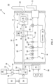
- FIG. 1 illustrates a test system 10 for testing one or more components of an engine.
- the engine may be described below as a gas turbine engine.
- the gas turbine engine include, but are not limited to, a turbofan engine, a turbojet engine, a turboprop engine, a turboshaft engine, an auxiliary power unit (APU) engine and an industrial engine.
- the test system 10 of the present disclosure is not limited to gas turbine engine applications.
- the test system 10 for example, may alternatively test component(s) for a reciprocating piston engine, a rotary engine (e.g., a Wenkel engine) or the like.
- the test system 10 of FIG. 1 includes a combustor test section 12 and an air system 14.
- the combustor test section 12 includes a test section housing 16, a fuel injector 18 and an ignitor 20.
- the test section housing 16 includes a housing inlet 22, a housing outlet 24 and a combustion chamber 26; e.g., an internal chamber.
- the housing inlet 22 is fluidly coupled with and downstream of the air system 14.
- the housing outlet 24 is fluidly coupled with and upstream of a combustion products exhaust 28 to an environment 30 external of the combustor test section 12 and, more generally, the test system 10.
- the combustion chamber 26 is within the test section housing 16.
- the combustion chamber 26 is fluidly coupled with and located between the housing inlet 22 and the housing outlet 24.
- the fuel injector 18 is configured to direct (e.g., inject) fuel into the combustion chamber 26.
- the ignitor 20 is configured to ignite a mixture of the fuel and compressed cooled air to generate combustion products within the combustion chamber 26.
- the combustor test section 12 is configured to receive the engine component(s) to be tested by the test system 10.
- the engine component(s) may be disposed within the combustion chamber 26.
- the engine component(s) may be arranged upstream of the combustion chamber 26; e.g., between the housing inlet 22 and the combustion chamber 26.
- the engine component(s) may be arranged downstream of the combustion chamber 26; e.g., between the combustion chamber 26 and the housing outlet 24.
- the engine component(s) may also or alternatively form a portion of the combustor test section 12.
- one of the engine component(s) may be the fuel injector 18 or a combustor wall forming a peripheral boundary of the combustion chamber 26.
- the present disclosure is not limited to such exemplary engine component(s) to be tested by the test system 10.
- the air system 14 is configured to deliver the compressed cooled air to the combustor test section 12.
- the air system 14 of FIG. 1 includes a compressed air source 32, an air dryer 34 and one or more air cooling systems 36 and 38.
- This air system 14 also includes an air circuit 40 (e.g., an open loop flowpath) which extends longitudinally between and fluidly couples an outlet from the compressed air source 32 and an inlet into the combustor test section 12.
- the air circuit 40 of FIG. 1 extends (e.g., sequentially) through the air dryer 34, a refrigeration heat exchanger 42 of the refrigeration cooling system 36 and a cryogenic heat exchanger 44 of the cryogenic cooling system 38.
- the compressed air source 32 is configured to output a flow of compressed air during operation of the test system 10.
- the compressed air source 32 may be or otherwise include a compressed air reservoir. Examples of the compressed air reservoir include a tank, a cylinder, a pressure vessel, a bladder or any other type of compressed air storage container.
- the compressed air source 32 may alternatively be or also include an air compressor. This air compressor may directly output the compressed air. Alternatively, the air compressor may charge the compressed air reservoir with the compressed air for subsequent output.
- the refrigeration cooling system 36 and its refrigeration heat exchanger 42 are configured to precool the (e.g., dried) compressed air to provide compressed precooled air.
- the refrigeration cooling system 36 of FIG. 1 for example, includes the refrigeration heat exchanger 42, a compressor 46, a condenser 48, an expansion valve 50 and refrigerant.
- the refrigeration cooling system members 42, 46, 48 and 50 of FIG. 1 are arranged in a closed loop refrigeration circuit 52, and the refrigerant is contained and circulated within the refrigeration circuit 52.
- the compressor 46 is configured to compress the refrigerant.
- the condenser 48 is configured to transfer heat energy out of the compressed refrigerant and into another fluid such as ambient air. The condenser 48 may thereby condense and cool the refrigerant flowing therethrough.
- the expansion valve 50 is configured to expand the cooled refrigerant thereacross.
- the refrigeration heat exchanger 42 of FIG. 1 is configured as an evaporator.
- This refrigeration heat exchanger 42 includes a refrigerant passage 54 and an air passage 56.
- the refrigerant passage 54 is part of the refrigeration circuit 52 and receives the expanded, cooled refrigerant from the expansion valve 50.
- the air passage 56 is part of the air circuit 40 and receives the dried compressed air from the air dryer 34.
- the refrigeration heat exchanger 42 (e.g., the evaporator) is configured to transfer heat energy out of the dried compressed air flowing in the air passage 56 and into the expanded, cooled refrigerant flowing in the refrigerant passage 54. The refrigeration heat exchanger 42 thereby precools the compressed air as well as evaporates the refrigerant to continue the refrigeration cycle.
- the cryogenic cooling system 38 and its cryogenic heat exchanger 44 are configured to further cool the (e.g., precooled) compressed air to provide the compressed cooled air to the combustor test section 12.
- the cryogenic cooling system 38 of FIG. 1 for example, includes a cryogenic liquid source 58, one or more valves 60-64, the cryogenic heat exchanger 44 and a flowmeter 66.
- This cryogenic cooling system 38 also includes one or more cryogenic cooling system circuits 68-70; e.g., open loop flowpaths.
- the source circuit 68 extends longitudinally between and fluidly couples an outlet from the cryogenic liquid source 58 and an inlet into the upstream pressure relief valve 60.
- the cryogenic liquid source 58 is configured to output a flow of a cryogenic liquid during operation of the test system 10.
- the cryogenic liquid include, but are not limited to, liquid nitrogen (N 2 ) and liquid helium (He).
- the cryogenic liquid source 58 may be or otherwise include one or more cryogenic liquid reservoirs 74. Examples of each cryogenic liquid reservoir 74 include a tank, a cylinder, a pressure vessel, a bladder or any other type of insulated cryogenic liquid storage container.
- the cryogenic liquid source 58 of FIG. 1 also includes a manifold 76, which manifold 76 fluidly couples the cryogenic liquid reservoirs 74 (e.g., in parallel) to the source circuit 68.
- the emergency shutoff valve 61 is configured to move between an (e.g., fully) open position and a (e.g., fully) closed position.
- the emergency shutoff valve 61 When the emergency shutoff valve 61 is in the open position, the cryogenic liquid may pass through the emergency shutoff valve 61 substantially unobstructed / unimpeded. However, when the emergency shutoff valve 61 is in the closed position, the emergency shutoff valve 61 may prevent (or substantially limit) the flow of the cryogenic liquid therethrough.
- This emergency shutoff valve 61 may be electronically controlled such that one or more safety systems for the test system 10 may automatically trigger the emergency shutoff valve 61 to close.
- the emergency shutoff valve 61 may also or alternatively be manually controlled such that personnel operating the test system 10 may manually trigger the emergency shutoff valve 61 to close.
- the control valve 62 is configured to move between an (e.g., fully) open position and a (e.g., fully or partially) closed position.
- the control valve 62 may (or may not) also be configured to move to and remain at one or more intermediate positions between the open position and the closed position.
- the control valve 62 When the control valve 62 is in the open position, the cryogenic liquid may pass through the control valve 62 substantially unobstructed / unimpeded. However, when the control valve 62 is in the closed position, the control valve 62 may prevent or reduce the flow of the cryogenic liquid therethrough.
- This control valve 62 may be electronically controlled by a controller 78.
- the controller 78 of FIG. 1 for example, is in signal communication with the control valve 62 and the flowmeter 66.
- the downstream pressure relief valve 63 When a pressure of the cryogenic liquid in an upstream portion 80 of the heat exchange circuit 69 is equal to or below a (e.g., set or variable) threshold value (e.g., during normal operation), the downstream pressure relief valve 63 is configured to (a) fluidly couple the upstream portion 80 of the heat exchange circuit 69 to a downstream portion 82 of the heat exchange circuit 69 and (b) fluidly decouple the upstream portion 80 of the heat exchange circuit 69 from the bypass circuit 70. However, in the event the pressure of the cryogenic liquid in the upstream portion 80 of the heat exchange circuit 69 rises above the threshold value, the downstream pressure relief valve 63 is configured to fluidly couple the upstream portion 80 of the heat exchange circuit 69 to the bypass circuit 70. The downstream pressure relief valve 63 may thereby bleed off (e.g., dump) some of the cryogenic liquid flowing in the heat exchange circuit 69 to reduce the pressure of the cryogenic liquid in the heat exchange circuit 69.
- a threshold value e.g.,
- the intermediate pressure relief valve 64 is configured to (a) fluidly couple the intermediate portion of the heat exchange circuit 69 to the downstream portion 82 of the heat exchange circuit 69 and (b) fluidly decouple the intermediate portion of the heat exchange circuit 69 from the bypass circuit 70.
- the intermediate pressure relief valve 64 is configured to fluidly couple the intermediate portion of the heat exchange circuit 69 to the bypass circuit 70.
- the intermediate pressure relief valve 64 may thereby bleed off (e.g., dump) some of the cryogenic liquid in the heat exchange circuit 69 to reduce the pressure of the cryogenic liquid in the heat exchange circuit 69.
- the air system 14 of the present disclosure may provide the compressed cooled air to the combustor test section 12 at a stable temperature well below the capability of a typical prior art cooling system.
- the air system 14 of the present disclosure may provide the compressed cooled air to the combustor test section 12 at a stable temperature equal to or below negative thirty degrees Fahrenheit (-30°F) (-34°C), negative thirty-five degrees Fahrenheit (-35°F) (-37°C) or negative forty degrees Fahrenheit (-40°F) (-40°C).
- the refrigeration cooling system 36 may output the compressed precooled air at a temperature between negative five degrees Fahrenheit (-5°F) (-21 °C) and negative fifteen degrees Fahrenheit (-15°F) (-26°C).
- a cost for cryogenic liquid such as liquid nitrogen is relatively inexpensive compared to costs associated with a typical prior art cooling system.
- test system components e.g., 12, 44, 60-63 and 66
- the other test system components e.g., 32, 34, 36 and 58
- the air system 14 may be configured without the refrigeration cooling system 36.
- the cryogenic cooling system 38 and/or the dry ice 88 may cool the ambient temperature compressed air received from the compressed air source 32 down to operating temperature.
- the air system 14 may be configured without the air dryer 34.
- the compressed precooled air is further cooled to operating temperature.
- the compressed precooled air output from the refrigeration heat exchanger 42 for example, is directed through the cryogenic heat exchanger 44.
- the cryogenic heat exchanger 44 transfers additional heat energy out of the compressed precooled air and into the cryogenic liquid flowing within the cryogenic liquid passage 84.
- the cryogenic heat exchanger 44 thereby further cools the compressed precooled air and outputs the compressed cooled air at operative temperature; e.g., at, about or between -30°F (-34°C) and -40°F (-40°C).
- step 208 the compressed cooled air is directed into the combustor test section 12 for operation of the combustor test section 12 and testing of the engine component(s).
- the air system 14 is described above as delivering the compressed cooled air to the combustor test section 12.
- the air system 14 of the present disclosure may alternatively provide the compressed cooled air to various other devices such as an insulated container in which the engine component(s) to be tested by the test system 10 are disposed. With such an arrangement, engine component(s) may be tested within a cold environment, rather than an environment of a combustor.
- the insulated container may have a similar configuration to the test section housing 16 described above.
Landscapes
- Engineering & Computer Science (AREA)
- Chemical & Material Sciences (AREA)
- Combustion & Propulsion (AREA)
- Physics & Mathematics (AREA)
- General Physics & Mathematics (AREA)
- Mechanical Engineering (AREA)
- General Engineering & Computer Science (AREA)
- Testing Of Engines (AREA)
- Testing Of Devices, Machine Parts, Or Other Structures Thereof (AREA)
Abstract
Description
- This disclosure relates generally to systems and methods for testing one or more components of an engine.
- A combustor test section may be used for testing one or more components of a gas turbine engine. The combustor test section may receive compressed air cooled by a refrigeration system. While such an engine component testing arrangement has various benefits, there is still room in the art for improvement.
- According to an aspect of the present disclosure, a test system is provided for a component of an engine. This test system includes a combustor test section and an air system. The combustor test section includes a fuel injector, an ignitor and a combustion chamber. The fuel injector is configured to direct fuel into the combustion chamber for mixing with cooled air. The ignitor is configured to ignite a mixture of the fuel and the cooled air within the combustion chamber. The air system is configured to deliver the cooled air to the combustor test section. The air system includes a compressed air source, a cryogenic cooling system and an air circuit. The cryogenic cooling system includes a cryogenic heat exchanger. The air circuit extends through the cryogenic heat exchanger and fluidly couples the compressed air source to the combustor test section.
- According to another aspect of the present disclosure, another test system is provided for a component of an engine. This test system includes a housing and an air system. The housing includes a chamber inlet, a chamber outlet and an internal chamber fluidly coupled with and between the chamber inlet and the chamber outlet. The housing is configured to receive the component of the engine within the internal chamber. The air system is configured to deliver cooled air to the internal chamber through the chamber inlet. The air system includes a compressed air source, a cryogenic cooling system and an air circuit. The cryogenic cooling system includes a cryogenic liquid source and a cryogenic heat exchanger. The cryogenic liquid source is configured to provide a cryogenic liquid to the cryogenic heat exchanger. The air circuit extends through the cryogenic heat exchanger and fluidly couples the compressed air source to the chamber inlet.
- According to still another aspect of the present disclosure, a method is provided for testing a component of an engine. This method includes: directing compressed air into an air passage of a cryogenic heat exchanger; directing a cryogenic liquid into a cryogenic liquid passage of the cryogenic heat exchanger; transferring heat energy from the compressed air in the air passage, through the cryogenic heat exchanger, into the cryogenic liquid in the cryogenic liquid passage to provide cooled air; and directing the cooled air into a housing. The component of the engine is disposed within an internal chamber of the housing.
- The following optional features may be applied to any of the above aspects.
- A combustor test section may include the housing. The internal chamber may include a combustion chamber.
- The method may include cooling the cryogenic heat exchanger with a quantity of dry ice.
- The method may include directing the compressed air through a refrigeration heat exchanger of a refrigeration cooling system to precool the compressed air. The refrigeration heat exchanger may be upstream of the cryogenic heat exchanger.
- The method may include directing the compressed air through an air dryer to lower a dewpoint temperature of the compressed air to negative fifty degrees Fahrenheit or lower. The air dryer may be upstream of the cryogenic heat exchanger.
- The cryogenic cooling system may also include a cryogenic liquid source. The cryogenic heat exchanger may include a cryogenic liquid passage and an air passage. The cryogenic liquid passage may be fluidly coupled with and downstream of the cryogenic liquid source. The air circuit may include the air passage.
- The cryogenic liquid passage may be configured to receive a cryogenic liquid from the cryogenic liquid source. The air passage may be configured to receive compressed air from the compressed air source. The cryogenic heat exchanger may be configured to transfer heat energy from the compressed air flowing in the air passage into the cryogenic liquid flowing in the cryogenic liquid passage.
- The cryogenic liquid source may be configured as or otherwise include a reservoir containing liquid nitrogen.
- The cryogenic cooling system may also include a heat exchange circuit, a bypass circuit and a pressure relief valve. The heat exchange circuit may include the cryogenic liquid passage. The bypass circuit may bypass the cryogenic heat exchanger. The heat exchange circuit and the bypass circuit may be downstream of and may be fluidly coupled to the cryogenic liquid source through the pressure relief valve.
- The cryogenic cooling system may also include an emergency shutoff valve fluidly coupled with and between the cryogenic liquid source and the cryogenic liquid passage.
- The cryogenic cooling system may also include a control valve fluidly coupled with and between the cryogenic liquid source and the cryogenic liquid passage.
- The cryogenic cooling system may also include a flowmeter and a controller in signal communication with the control valve and the flowmeter. The controller may be configured to control operation of the control valve based on a signal output from the flowmeter.
- The cryogenic liquid passage may be fluidly coupled with and between the control valve and the flowmeter. The flowmeter may be downstream of the cryogenic liquid passage.
- The test system may also include a quantity of dry ice arranged with the cryogenic heat exchanger.
- The air system may also include a refrigeration cooling system with a refrigeration heat exchanger. The air circuit may also extend through the refrigeration heat exchanger. The cryogenic heat exchanger may be between the refrigeration heat exchanger and the combustor test section along the air circuit.
- The air system may also include an air dryer. The air circuit may extend through the air dryer. The cryogenic heat exchanger may be between the air dryer and the combustor test section along the air circuit.
- The air dryer may be configured to lower a dewpoint temperature of compressed air received from the compressed air source to negative fifty degrees Fahrenheit or lower.
- The test system may also include a combustor test section which includes the housing.
- The housing may be configured as or otherwise include an insulated container.
- The present disclosure may include any one or more of the individual features disclosed above and/or below alone or in any combination thereof.
- The foregoing features and the operation of the invention will become more apparent in light of the following description and the accompanying drawings.
-
-
FIG. 1 is a schematic illustration of a test system for testing one or more components of an engine. -
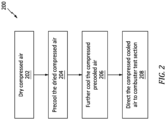
FIG. 2 is a flow diagram of a method for testing the one or more components of the engine. -
FIG. 1 illustrates atest system 10 for testing one or more components of an engine. For ease of description, the engine may be described below as a gas turbine engine. Examples of the gas turbine engine include, but are not limited to, a turbofan engine, a turbojet engine, a turboprop engine, a turboshaft engine, an auxiliary power unit (APU) engine and an industrial engine. Thetest system 10 of the present disclosure, however, is not limited to gas turbine engine applications. Thetest system 10, for example, may alternatively test component(s) for a reciprocating piston engine, a rotary engine (e.g., a Wenkel engine) or the like. Thetest system 10 ofFIG. 1 includes acombustor test section 12 and anair system 14. - The
combustor test section 12 includes atest section housing 16, afuel injector 18 and anignitor 20. Thetest section housing 16 includes ahousing inlet 22, ahousing outlet 24 and acombustion chamber 26; e.g., an internal chamber. Thehousing inlet 22 is fluidly coupled with and downstream of theair system 14. Thehousing outlet 24 is fluidly coupled with and upstream of a combustion products exhaust 28 to anenvironment 30 external of thecombustor test section 12 and, more generally, thetest system 10. Thecombustion chamber 26 is within thetest section housing 16. Thecombustion chamber 26 is fluidly coupled with and located between thehousing inlet 22 and thehousing outlet 24. Thefuel injector 18 is configured to direct (e.g., inject) fuel into thecombustion chamber 26. Theignitor 20 is configured to ignite a mixture of the fuel and compressed cooled air to generate combustion products within thecombustion chamber 26. - The
combustor test section 12 is configured to receive the engine component(s) to be tested by thetest system 10. The engine component(s), for example, may be disposed within thecombustion chamber 26. The engine component(s) may be arranged upstream of thecombustion chamber 26; e.g., between thehousing inlet 22 and thecombustion chamber 26. The engine component(s) may be arranged downstream of thecombustion chamber 26; e.g., between thecombustion chamber 26 and thehousing outlet 24. The engine component(s) may also or alternatively form a portion of thecombustor test section 12. For example, one of the engine component(s) may be thefuel injector 18 or a combustor wall forming a peripheral boundary of thecombustion chamber 26. The present disclosure, however, is not limited to such exemplary engine component(s) to be tested by thetest system 10. - The
air system 14 is configured to deliver the compressed cooled air to thecombustor test section 12. Theair system 14 ofFIG. 1 includes acompressed air source 32, anair dryer 34 and one or moreair cooling systems air system 14 also includes an air circuit 40 (e.g., an open loop flowpath) which extends longitudinally between and fluidly couples an outlet from the compressedair source 32 and an inlet into thecombustor test section 12. Between thecompressed air source 32 and thecombustor test section 12, theair circuit 40 ofFIG. 1 extends (e.g., sequentially) through theair dryer 34, arefrigeration heat exchanger 42 of therefrigeration cooling system 36 and acryogenic heat exchanger 44 of thecryogenic cooling system 38. - The
compressed air source 32 is configured to output a flow of compressed air during operation of thetest system 10. Thecompressed air source 32, for example, may be or otherwise include a compressed air reservoir. Examples of the compressed air reservoir include a tank, a cylinder, a pressure vessel, a bladder or any other type of compressed air storage container. Thecompressed air source 32 may alternatively be or also include an air compressor. This air compressor may directly output the compressed air. Alternatively, the air compressor may charge the compressed air reservoir with the compressed air for subsequent output. - The
air dryer 34 is configured to dry the compressed air to provide dried compressed air. More particularly, theair dryer 34 is configured to remove moisture from the compressed air in order to lower a dewpoint temperature of the compressed air. Theair dryer 34 ofFIG. 1 , for example, may be sized and configured to lower the dewpoint temperature of the compressed air below minus thirty or forty degrees Fahrenheit (-30°F, -40°F) (about -34°C or -40°C); e.g., equal to or below minus fifty degrees Fahrenheit (-50°F) (-46°C) or below. - The
refrigeration cooling system 36 and itsrefrigeration heat exchanger 42 are configured to precool the (e.g., dried) compressed air to provide compressed precooled air. Therefrigeration cooling system 36 ofFIG. 1 , for example, includes therefrigeration heat exchanger 42, acompressor 46, acondenser 48, anexpansion valve 50 and refrigerant. The refrigerationcooling system members FIG. 1 are arranged in a closedloop refrigeration circuit 52, and the refrigerant is contained and circulated within therefrigeration circuit 52. Thecompressor 46 is configured to compress the refrigerant. Thecondenser 48 is configured to transfer heat energy out of the compressed refrigerant and into another fluid such as ambient air. Thecondenser 48 may thereby condense and cool the refrigerant flowing therethrough. Theexpansion valve 50 is configured to expand the cooled refrigerant thereacross. Therefrigeration heat exchanger 42 ofFIG. 1 is configured as an evaporator. Thisrefrigeration heat exchanger 42 includes arefrigerant passage 54 and anair passage 56. Therefrigerant passage 54 is part of therefrigeration circuit 52 and receives the expanded, cooled refrigerant from theexpansion valve 50. Theair passage 56 is part of theair circuit 40 and receives the dried compressed air from theair dryer 34. The refrigeration heat exchanger 42 (e.g., the evaporator) is configured to transfer heat energy out of the dried compressed air flowing in theair passage 56 and into the expanded, cooled refrigerant flowing in therefrigerant passage 54. Therefrigeration heat exchanger 42 thereby precools the compressed air as well as evaporates the refrigerant to continue the refrigeration cycle. - The
cryogenic cooling system 38 and itscryogenic heat exchanger 44 are configured to further cool the (e.g., precooled) compressed air to provide the compressed cooled air to thecombustor test section 12. Thecryogenic cooling system 38 ofFIG. 1 , for example, includes a cryogenicliquid source 58, one or more valves 60-64, thecryogenic heat exchanger 44 and aflowmeter 66. Thiscryogenic cooling system 38 also includes one or more cryogenic cooling system circuits 68-70; e.g., open loop flowpaths. Thesource circuit 68 extends longitudinally between and fluidly couples an outlet from the cryogenicliquid source 58 and an inlet into the upstreampressure relief valve 60. Theheat exchange circuit 69 extends longitudinally between and fluidly couples a first outlet from the upstreampressure relief valve 60 and a cryogenicfluid exhaust 72 to theexternal environment 30. Between the upstreampressure relief valve 60 and the cryogenicfluid exhaust 72, theheat exchange circuit 69 ofFIG. 1 extends (e.g., sequentially) through theemergency shutoff valve 61, the intermediatepressure relief valve 64, thecontrol valve 62, the downstreampressure relief valve 63, thecryogenic heat exchanger 44 and theflowmeter 66. Thebypass circuit 70 extends longitudinally between and fluidly couples a second outlet from the upstreampressure relief valve 60 and the cryogenicfluid exhaust 72. Thisbypass circuit 70 bypasses (e.g., does not extend through, may not be fluidly coupled with) each of the cryogeniccooling system members FIG. 1 , theheat exchange circuit 69 and thebypass circuit 70 are fluidly coupled in parallel between thesource circuit 68 and the cryogenicfluid exhaust 72. - The cryogenic
liquid source 58 is configured to output a flow of a cryogenic liquid during operation of thetest system 10. Examples of the cryogenic liquid include, but are not limited to, liquid nitrogen (N2) and liquid helium (He). The cryogenicliquid source 58 may be or otherwise include one or more cryogenicliquid reservoirs 74. Examples of eachcryogenic liquid reservoir 74 include a tank, a cylinder, a pressure vessel, a bladder or any other type of insulated cryogenic liquid storage container. The cryogenicliquid source 58 ofFIG. 1 also includes a manifold 76, whichmanifold 76 fluidly couples the cryogenic liquid reservoirs 74 (e.g., in parallel) to thesource circuit 68. - When a pressure of the cryogenic liquid in the
source circuit 68 is equal to or below a (e.g., set or variable) threshold value (e.g., during normal operation), the upstreampressure relief valve 60 is configured to (a) fluidly couple thesource circuit 68 to theheat exchange circuit 69 and (b) fluidly decouple thesource circuit 68 from thebypass circuit 70. However, in the event the pressure of the cryogenic liquid in thesource circuit 68 rises above the threshold value, the upstreampressure relief valve 60 is configured to fluidly couple thesource circuit 68 to thebypass circuit 70. The upstreampressure relief valve 60 may thereby bleed off (e.g., dump) some of the cryogenic liquid flowing from thesource circuit 68 to theheat exchange circuit 69 to reduce the pressure of the cryogenic liquid in thesource circuit 68. - The
emergency shutoff valve 61 is configured to move between an (e.g., fully) open position and a (e.g., fully) closed position. When theemergency shutoff valve 61 is in the open position, the cryogenic liquid may pass through theemergency shutoff valve 61 substantially unobstructed / unimpeded. However, when theemergency shutoff valve 61 is in the closed position, theemergency shutoff valve 61 may prevent (or substantially limit) the flow of the cryogenic liquid therethrough. Thisemergency shutoff valve 61 may be electronically controlled such that one or more safety systems for thetest system 10 may automatically trigger theemergency shutoff valve 61 to close. Theemergency shutoff valve 61 may also or alternatively be manually controlled such that personnel operating thetest system 10 may manually trigger theemergency shutoff valve 61 to close. - The
control valve 62 is configured to move between an (e.g., fully) open position and a (e.g., fully or partially) closed position. Thecontrol valve 62 may (or may not) also be configured to move to and remain at one or more intermediate positions between the open position and the closed position. When thecontrol valve 62 is in the open position, the cryogenic liquid may pass through thecontrol valve 62 substantially unobstructed / unimpeded. However, when thecontrol valve 62 is in the closed position, thecontrol valve 62 may prevent or reduce the flow of the cryogenic liquid therethrough. Thiscontrol valve 62 may be electronically controlled by acontroller 78. Thecontroller 78 ofFIG. 1 , for example, is in signal communication with thecontrol valve 62 and theflowmeter 66. Thiscontroller 78 may be configured to control operation of the control valve 62 (e.g., control how much thecontrol valve 62 is opened or closed / control a position of the control valve 62) based on a signal output from theflowmeter 66. Thus, a flowrate and/or a pressure of the cryogenic liquid flowing through theheat exchange circuit 69 to thecryogenic heat exchanger 44 may be tailored based on feedback from theflowmeter 66. Moreover, thecontroller 78 may tailor the flowrate and/or the pressure of the cryogenic liquid flowing to thecryogenic heat exchanger 44 such that the compressed cooled air output from thecryogenic heat exchanger 44 has a select temperature (or is within a select temperature range). While theflowmeter 66 ofFIG. 1 is positioned downstream of thecryogenic heat exchanger 44 inFIG. 1 , it is contemplated theflowmeter 66 may alternatively be positioned upstream of thecryogenic heat exchanger 44 or elsewhere in other embodiments. - When a pressure of the cryogenic liquid in an
upstream portion 80 of theheat exchange circuit 69 is equal to or below a (e.g., set or variable) threshold value (e.g., during normal operation), the downstreampressure relief valve 63 is configured to (a) fluidly couple theupstream portion 80 of theheat exchange circuit 69 to adownstream portion 82 of theheat exchange circuit 69 and (b) fluidly decouple theupstream portion 80 of theheat exchange circuit 69 from thebypass circuit 70. However, in the event the pressure of the cryogenic liquid in theupstream portion 80 of theheat exchange circuit 69 rises above the threshold value, the downstreampressure relief valve 63 is configured to fluidly couple theupstream portion 80 of theheat exchange circuit 69 to thebypass circuit 70. The downstreampressure relief valve 63 may thereby bleed off (e.g., dump) some of the cryogenic liquid flowing in theheat exchange circuit 69 to reduce the pressure of the cryogenic liquid in theheat exchange circuit 69. - When a pressure of the cryogenic liquid in an intermediate portion of the
heat exchange circuit 69 between thevalves pressure relief valve 64 is configured to (a) fluidly couple the intermediate portion of theheat exchange circuit 69 to thedownstream portion 82 of theheat exchange circuit 69 and (b) fluidly decouple the intermediate portion of theheat exchange circuit 69 from thebypass circuit 70. However, in the event the pressure of the cryogenic liquid in the intermediate portion of theheat exchange circuit 69 rises above the threshold value (e.g., in an unlikely event thevalves pressure relief valve 64 is configured to fluidly couple the intermediate portion of theheat exchange circuit 69 to thebypass circuit 70. The intermediatepressure relief valve 64 may thereby bleed off (e.g., dump) some of the cryogenic liquid in theheat exchange circuit 69 to reduce the pressure of the cryogenic liquid in theheat exchange circuit 69. - This
cryogenic heat exchanger 44 includes acryogenic liquid passage 84 and anair passage 86. Thecryogenic liquid passage 84 is part of theheat exchange circuit 69 and receives the cryogenic liquid from the cryogenicliquid source 58. Theair passage 86 is part of theair circuit 40 and receives the compressed precooled air from therefrigeration cooling system 36. Thecryogenic heat exchanger 44 is configured to transfer heat energy out of the compressed precooled air flowing in theair passage 86 and into the cryogenic liquid flowing in thecryogenic liquid passage 84. Thecryogenic heat exchanger 44 thereby further cools the compressed precooled air and outputs the compressed cooled air to thecombustor test section 12. As the compressed air is cooled, the cryogenic liquid may change phase into a gaseous cryogenic fluid. This gaseous cryogenic fluid is provided to the cryogenicfluid exhaust 72 for exhausting into theexternal environment 30. - In some embodiments, a quantity of
dry ice 88 may also be arranged with thecryogenic heat exchanger 44. Thedry ice 88, for example, may be placed on top of thecryogenic heat exchanger 44, on a side of thecryogenic heat exchanger 44 and/or in a compartment of thecryogenic heat exchanger 44. Provision of thedry ice 88 may reduce an initial cooldown time of the cryogenic heat exchanger 44 (e.g., at a start of operation of the test system 10). Provision of thedry ice 88 may also provide supplemental cooling of the compressed air flowing through theair passage 86. In particular, thecryogenic heat exchanger 44 may also transfer heat energy out of the compressed precooled air flowing in theair passage 86 and into thedry ice 88. - By utilizing the cryogenic liquid (and optionally the dry ice 88), the
air system 14 of the present disclosure may provide the compressed cooled air to thecombustor test section 12 at a stable temperature well below the capability of a typical prior art cooling system. Theair system 14 of the present disclosure, for example, may provide the compressed cooled air to thecombustor test section 12 at a stable temperature equal to or below negative thirty degrees Fahrenheit (-30°F) (-34°C), negative thirty-five degrees Fahrenheit (-35°F) (-37°C) or negative forty degrees Fahrenheit (-40°F) (-40°C). Therefrigeration cooling system 36, on the other hand, may output the compressed precooled air at a temperature between negative five degrees Fahrenheit (-5°F) (-21 °C) and negative fifteen degrees Fahrenheit (-15°F) (-26°C). Moreover, a cost for cryogenic liquid such as liquid nitrogen is relatively inexpensive compared to costs associated with a typical prior art cooling system. - In some embodiments, one or more of the test system components (e.g., 12, 44, 60-63 and 66) may be arranged within a
test cell 90 while one or more of the other test system components (e.g., 32, 34, 36 and 58) may be arranged outside of thetest cell 90. - In some embodiments, the
air system 14 may be configured without therefrigeration cooling system 36. In such embodiments, thecryogenic cooling system 38 and/or thedry ice 88 may cool the ambient temperature compressed air received from the compressedair source 32 down to operating temperature. - In some embodiments, the
air system 14 may be configured without theair dryer 34. -
FIG. 2 is a flow diagram of amethod 200 for testing one or more components of an engine. For ease of description, thetest method 200 is described below with respect to thetest system 10 ofFIG. 1 . Thetest method 200 of the present disclosure, however, is not limited to utilizing such an exemplary test system. - In
step 202, compressed air is dried. The compressed air output from the compressedair source 32, for example, is directed through theair dryer 34 to lower the dewpoint temperature of the compressed air below minus thirty or forty degrees Fahrenheit (-30°F, -40°F) (-34°C, -40°C); e.g., equal to or below minus fifty degrees Fahrenheit (-50°F) (-46°C) or below. - In
step 204, the dried compressed air is precooled. The dried compressed air output from theair dryer 34, for example, is directed through therefrigeration heat exchanger 42. As the dried compressed air flows within theair passage 56, therefrigeration heat exchanger 42 transfers heat energy out of the dried compressed air and into the refrigerant within therefrigerant passage 54. Therefrigeration heat exchanger 42 thereby cools the dried compressed air and outputs compressed precooled air. - In
step 206, the compressed precooled air is further cooled to operating temperature. The compressed precooled air output from therefrigeration heat exchanger 42, for example, is directed through thecryogenic heat exchanger 44. As the compressed precooled air flows within theair passage 86, thecryogenic heat exchanger 44 transfers additional heat energy out of the compressed precooled air and into the cryogenic liquid flowing within thecryogenic liquid passage 84. Thecryogenic heat exchanger 44 thereby further cools the compressed precooled air and outputs the compressed cooled air at operative temperature; e.g., at, about or between -30°F (-34°C) and -40°F (-40°C). - In step 208, the compressed cooled air is directed into the
combustor test section 12 for operation of thecombustor test section 12 and testing of the engine component(s). - The
air system 14 is described above as delivering the compressed cooled air to thecombustor test section 12. Theair system 14 of the present disclosure, however, may alternatively provide the compressed cooled air to various other devices such as an insulated container in which the engine component(s) to be tested by thetest system 10 are disposed. With such an arrangement, engine component(s) may be tested within a cold environment, rather than an environment of a combustor. The insulated container, however, may have a similar configuration to thetest section housing 16 described above. - While various embodiments of the present disclosure have been described, it will be apparent to those of ordinary skill in the art that many more embodiments and implementations are possible within the scope of the disclosure. For example, the present disclosure as described herein includes several aspects and embodiments that include particular features. Although these features may be described individually, it is within the scope of the present disclosure that some or all of these features may be combined with any one of the aspects and remain within the scope of the disclosure. Accordingly, the present disclosure is not to be restricted except in light of the attached claims and their equivalents.
Claims (15)
- A test system (10) for a component of an engine, comprising:a combustor test section (12) including a fuel inj ector (18), an ignitor (20) and a combustion chamber (26), the fuel injector (18) configured to direct fuel into the combustion chamber (26) for mixing with cooled air, and the ignitor (20) configured to ignite a mixture of the fuel and the cooled air within the combustion chamber (26); andan air system (14) configured to deliver the cooled air to the combustor test section (12), the air system (14) including a compressed air source (32), a cryogenic cooling system (38) and an air circuit (40), the cryogenic cooling system (38) comprising a cryogenic heat exchanger (44), and the air circuit (40) extending through the cryogenic heat exchanger (44) and fluidly coupling the compressed air source (32) to the combustor test section (12).
- The test system (10) of claim 1, wherein:the cryogenic cooling system (38) further comprises a cryogenic liquid source (58);the cryogenic heat exchanger (44) includes a cryogenic liquid passage (84) and an air passage (86);the cryogenic liquid passage (84) is fluidly coupled with and downstream of the cryogenic liquid source (58); andthe air circuit (40) comprises the air passage (86).
- The test system (10) of claim 2, wherein:the cryogenic liquid passage (84) is configured to receive a cryogenic liquid from the cryogenic liquid source (58);the air passage (86) is configured to receive compressed air from the compressed air source (32); andthe cryogenic heat exchanger (44) is configured to transfer heat energy from the compressed air flowing in the air passage (86) into the cryogenic liquid flowing in the cryogenic liquid passage (84).
- The test system (10) of claim 2 or 3, wherein the cryogenic liquid source (58) comprises a reservoir (74) containing liquid nitrogen.
- The test system (10) of claim 2, 3 or 4, wherein:the cryogenic cooling system (38) further comprises a heat exchange circuit (69), a bypass circuit (70) and a pressure relief valve (60);the heat exchange circuit (69) comprises the cryogenic liquid passage (84);the bypass circuit (70) bypasses the cryogenic heat exchanger (44); andthe heat exchange circuit (69) and the bypass circuit (70) are downstream of and fluidly coupled to the cryogenic liquid source (58) through the pressure relief valve (60).
- The test system (10) of any of claims 2 to 5, wherein the cryogenic cooling system (38) further comprises an emergency shutoff valve (61) fluidly coupled with and between the cryogenic liquid source (58) and the cryogenic liquid passage (84).
- The test system (10) of any of claims 2 to 6, wherein the cryogenic cooling system (38) further comprises a control valve (62) fluidly coupled with and between the cryogenic liquid source (58) and the cryogenic liquid passage (84).
- The test system (10) of claim 7, wherein:the cryogenic cooling system (38) further comprises a flowmeter (66) and a controller (78) in signal communication with the control valve (62) and the flowmeter (66); andthe controller (78) is configured to control operation of the control valve (62) based on a signal output from the flowmeter (66).
- The test system (10) of claim 8, wherein the cryogenic liquid passage (84) is fluidly coupled with and between the control valve (62) and the flowmeter (66), and the flowmeter (66) is downstream of the cryogenic liquid passage (84).
- The test system (10) of any preceding claim, further comprising a quantity of dry ice (88) arranged with the cryogenic heat exchanger (44).
- The test system (10) of any preceding claim, wherein:the air system (14) further includes a refrigeration cooling system (36) with a refrigeration heat exchanger (42);the air circuit (40) further extends through the refrigeration heat exchanger (42); andthe cryogenic heat exchanger (44) is between the refrigeration heat exchanger (42) and the combustor test section (12) along the air circuit (40).
- The test system (10) of any preceding claim, wherein:the air system (14) further includes an air dryer (34);the air circuit (40) further extends through the air dryer (34); andthe cryogenic heat exchanger (44) is between the air dryer (34) and the combustor test section (12) along the air circuit (40),wherein, optionally, the air dryer (34) is configured to lower a dewpoint temperature of compressed air received from the compressed air source (32) to negative fifty degrees Fahrenheit (-45°C) or lower.
- A test system (10) for a component of an engine, comprising:a housing (16) including a chamber inlet (22), a chamber outlet (24) and an internal chamber (26) fluidly coupled with and between the chamber inlet (22) and the chamber outlet (24), the housing (16) configured to receive the component of the engine within the internal chamber (26); andan air system (14) configured to deliver cooled air to the internal chamber (26) through the chamber inlet (22), the air system (14) including a compressed air source (32), a cryogenic cooling system (38) and an air circuit (40), the cryogenic cooling system (38) including a cryogenic liquid source (58) and a cryogenic heat exchanger (44), the cryogenic liquid source (58) configured to provide a cryogenic liquid to the cryogenic heat exchanger (44), and the air circuit (40) extending through the cryogenic heat exchanger (44) and fluidly coupling the compressed air source (32) to the chamber inlet (22),wherein, optionally, the test system (20) further comprises a combustor test section (12) which includes the housing (16).
- A method for testing a component of an engine, comprising:directing compressed air into an air passage (86) of a cryogenic heat exchanger (44);directing a cryogenic liquid into a cryogenic liquid passage (84) of the cryogenic heat exchanger(44);transferring heat energy from the compressed air in the air passage (86), through the cryogenic heat exchanger (44), into the cryogenic liquid in the cryogenic liquid passage (84) to provide cooled air; anddirecting the cooled air into a housing (16), wherein the component of the engine is disposed within an internal chamber (26) of the housing (16),wherein, optionally:a combustor test section (12) includes the housing (16); andthe internal chamber (26) comprises a combustion chamber (26).
- The method of claim 14, further comprising:cooling the cryogenic heat exchanger (44) with a quantity of dry ice (88); and/ordirecting the compressed air through a refrigeration heat exchanger (42) of a refrigeration cooling system (36) to precool the compressed air, wherein the refrigeration heat exchanger (42) is upstream of the cryogenic heat exchanger (44); and/ordirecting the compressed air through an air dryer (34) to lower a dewpoint temperature of the compressed air to negative fifty degrees Fahrenheit (-45°C) or lower, wherein the air dryer (34) is upstream of the cryogenic heat exchanger (44).
Applications Claiming Priority (1)
| Application Number | Priority Date | Filing Date | Title |
|---|---|---|---|
| US18/377,434 US12704437B2 (en) | 2023-10-06 | 2023-10-06 | Engine component test system with cryogenic cooling system |
Publications (1)
| Publication Number | Publication Date |
|---|---|
| EP4534970A1 true EP4534970A1 (en) | 2025-04-09 |
Family
ID=93014830
Family Applications (1)
| Application Number | Title | Priority Date | Filing Date |
|---|---|---|---|
| EP24205040.9A Pending EP4534970A1 (en) | 2023-10-06 | 2024-10-07 | Engine component test system with cryogenic cooling system |
Country Status (3)
| Country | Link |
|---|---|
| US (1) | US12704437B2 (en) |
| EP (1) | EP4534970A1 (en) |
| CA (1) | CA3255440A1 (en) |
Citations (6)
| Publication number | Priority date | Publication date | Assignee | Title |
|---|---|---|---|---|
| JPS59193334A (en) * | 1983-04-19 | 1984-11-01 | Mitsubishi Heavy Ind Ltd | Fastening method of blade root in statical vibration test of actual machine |
| CN104634578A (en) * | 2015-03-09 | 2015-05-20 | 北京动力机械研究所 | Total environment high-altitude test system and total environment high-altitude test method for aviation turbocharged internal combustion engine |
| US20160305436A1 (en) * | 2011-03-29 | 2016-10-20 | Joseph D. Brostmeyer | Process for testing a compressor or a combustor of a gas turbine engine using a large compressed air storage reservoir |
| CN112881021A (en) * | 2021-03-31 | 2021-06-01 | 中国科学院工程热物理研究所 | Test device capable of simulating high-altitude low-temperature low-pressure environment of engine combustion chamber |
| CN113606067A (en) * | 2021-07-28 | 2021-11-05 | 西安航天动力试验技术研究所 | High-precision supply system and method for low-temperature incoming flow working medium |
| CN217288756U (en) * | 2022-01-20 | 2022-08-26 | 上海奥然科贸有限公司 | Ventilation type liquid nitrogen and dry ice rapid cooling device for grinding bead homogenizer |
Family Cites Families (6)
| Publication number | Priority date | Publication date | Assignee | Title |
|---|---|---|---|---|
| US7174797B2 (en) | 2002-10-15 | 2007-02-13 | Florida Turbine Technologies, Inc. | High temperature and pressure testing facility |
| GB2431225B (en) * | 2005-10-15 | 2008-06-18 | Rolls Royce Plc | Combustor and component for a combustor |
| US7958777B1 (en) | 2008-10-07 | 2011-06-14 | Florida Turbine Technologies, Inc. | Thermal mechanical fatigue test rig |
| US8281649B1 (en) | 2010-06-11 | 2012-10-09 | Florida Turbine Technologies, Inc. | Advanced hot section materials and coatings test rig |
| US20160030607A1 (en) * | 2014-08-04 | 2016-02-04 | Michael D. Newman | Heat flux control for liquid nitrogen sprays |
| CN116067663B (en) | 2023-01-06 | 2025-09-02 | 中国航发沈阳发动机研究所 | A ground high and low temperature starting test equipment for aircraft engines |
-
2023
- 2023-10-06 US US18/377,434 patent/US12704437B2/en active Active
-
2024
- 2024-10-03 CA CA3255440A patent/CA3255440A1/en active Pending
- 2024-10-07 EP EP24205040.9A patent/EP4534970A1/en active Pending
Patent Citations (6)
| Publication number | Priority date | Publication date | Assignee | Title |
|---|---|---|---|---|
| JPS59193334A (en) * | 1983-04-19 | 1984-11-01 | Mitsubishi Heavy Ind Ltd | Fastening method of blade root in statical vibration test of actual machine |
| US20160305436A1 (en) * | 2011-03-29 | 2016-10-20 | Joseph D. Brostmeyer | Process for testing a compressor or a combustor of a gas turbine engine using a large compressed air storage reservoir |
| CN104634578A (en) * | 2015-03-09 | 2015-05-20 | 北京动力机械研究所 | Total environment high-altitude test system and total environment high-altitude test method for aviation turbocharged internal combustion engine |
| CN112881021A (en) * | 2021-03-31 | 2021-06-01 | 中国科学院工程热物理研究所 | Test device capable of simulating high-altitude low-temperature low-pressure environment of engine combustion chamber |
| CN113606067A (en) * | 2021-07-28 | 2021-11-05 | 西安航天动力试验技术研究所 | High-precision supply system and method for low-temperature incoming flow working medium |
| CN217288756U (en) * | 2022-01-20 | 2022-08-26 | 上海奥然科贸有限公司 | Ventilation type liquid nitrogen and dry ice rapid cooling device for grinding bead homogenizer |
Non-Patent Citations (3)
| Title |
|---|
| DATABASE WPI Week 201557, Derwent World Patents Index; AN 2015-43925B, XP002812874 * |
| DATABASE WPI Week 2021051, Derwent World Patents Index; AN 2021-641363, XP002812872 * |
| DATABASE WPI Week 2022013, Derwent World Patents Index; AN 2021-C9155L, XP002812873 * |
Also Published As
| Publication number | Publication date |
|---|---|
| US12704437B2 (en) | 2026-08-11 |
| CA3255440A1 (en) | 2025-05-23 |
| US20250116571A1 (en) | 2025-04-10 |
Similar Documents
| Publication | Publication Date | Title |
|---|---|---|
| US10794285B2 (en) | Gas turbine air injection system control and method of operation | |
| US11773782B2 (en) | Gas turbine engines having cryogenic fuel systems | |
| US12385438B2 (en) | Installation for heating a cryogenic fuel | |
| RU2623336C2 (en) | Gas turbine with adjustable air cooling system | |
| US20250198330A1 (en) | Hydrogen turbine power assisted condensation | |
| US9765700B2 (en) | Bleed air systems for use with aircrafts and related methods | |
| US7124591B2 (en) | Method for operating a gas turbine | |
| US5438823A (en) | Heat exchange apparatus for gas turbine fluids | |
| US6385958B2 (en) | Method for pressure modulation of turbine sidewall cavities | |
| EP1484489B1 (en) | Intake air cooling system for a gas turbine engine | |
| US20140126991A1 (en) | Systems and methods for active component life management for gas turbine engines | |
| US8984893B2 (en) | System and method for augmenting gas turbine power output | |
| CN112081670B (en) | Forced air convection apparatus and method for cooling a turbine | |
| US12071257B2 (en) | Hybrid electric hydrogen engine for aircraft | |
| US12031485B1 (en) | Water storage precooling and water cycle chiller | |
| US20240384907A1 (en) | Vapor cycle system for cooling components and associated method | |
| US20250116571A1 (en) | Engine component test system with cryogenic cooling system | |
| JP3206749B2 (en) | Compressor testing apparatus and compressor testing method using the same | |
| CN118936900B (en) | A high-altitude ignition test system for multiple combustion chambers | |
| US20190153961A1 (en) | Gas turbine system | |
| Olkhovski et al. | Variable Modes of Operation of Combined-Cycle Gas-Turbine Units | |
| CN117554828A (en) | High-low temperature environment simulation cabin suitable for hydrogen fuel cell system test |
Legal Events
| Date | Code | Title | Description |
|---|---|---|---|
| PUAI | Public reference made under article 153(3) epc to a published international application that has entered the european phase |
Free format text: ORIGINAL CODE: 0009012 |
|
| STAA | Information on the status of an ep patent application or granted ep patent |
Free format text: STATUS: THE APPLICATION HAS BEEN PUBLISHED |
|
| AK | Designated contracting states |
Kind code of ref document: A1 Designated state(s): AL AT BE BG CH CY CZ DE DK EE ES FI FR GB GR HR HU IE IS IT LI LT LU LV MC ME MK MT NL NO PL PT RO RS SE SI SK SM TR |
|
| STAA | Information on the status of an ep patent application or granted ep patent |
Free format text: STATUS: REQUEST FOR EXAMINATION WAS MADE |
|
| 17P | Request for examination filed |
Effective date: 20251009 |
|
| STAA | Information on the status of an ep patent application or granted ep patent |
Free format text: STATUS: EXAMINATION IS IN PROGRESS |
|
| 17Q | First examination report despatched |
Effective date: 20260401 |