EP4534909A1 - Aft inner cap plate removal method and tooling for a combustor with micromixer tubes - Google Patents
Aft inner cap plate removal method and tooling for a combustor with micromixer tubes Download PDFInfo
- Publication number
- EP4534909A1 EP4534909A1 EP24199187.6A EP24199187A EP4534909A1 EP 4534909 A1 EP4534909 A1 EP 4534909A1 EP 24199187 A EP24199187 A EP 24199187A EP 4534909 A1 EP4534909 A1 EP 4534909A1
- Authority
- EP
- European Patent Office
- Prior art keywords
- aft plate
- feet
- upper housing
- removal tool
- aft
- Prior art date
- Legal status (The legal status is an assumption and is not a legal conclusion. Google has not performed a legal analysis and makes no representation as to the accuracy of the status listed.)
- Pending
Links
Images




Classifications
-
- B—PERFORMING OPERATIONS; TRANSPORTING
- B25—HAND TOOLS; PORTABLE POWER-DRIVEN TOOLS; MANIPULATORS
- B25B—TOOLS OR BENCH DEVICES NOT OTHERWISE PROVIDED FOR, FOR FASTENING, CONNECTING, DISENGAGING, OR HOLDING
- B25B27/00—Hand tools, specially adapted for fitting together or separating parts or objects whether or not involving some deformation, not otherwise provided for
- B25B27/14—Hand tools, specially adapted for fitting together or separating parts or objects whether or not involving some deformation, not otherwise provided for for assembling objects other than by press fit or detaching same
-
- B—PERFORMING OPERATIONS; TRANSPORTING
- B25—HAND TOOLS; PORTABLE POWER-DRIVEN TOOLS; MANIPULATORS
- B25B—TOOLS OR BENCH DEVICES NOT OTHERWISE PROVIDED FOR, FOR FASTENING, CONNECTING, DISENGAGING, OR HOLDING
- B25B27/00—Hand tools, specially adapted for fitting together or separating parts or objects whether or not involving some deformation, not otherwise provided for
- B25B27/02—Hand tools, specially adapted for fitting together or separating parts or objects whether or not involving some deformation, not otherwise provided for for connecting objects by press fit or detaching same
- B25B27/023—Hand tools, specially adapted for fitting together or separating parts or objects whether or not involving some deformation, not otherwise provided for for connecting objects by press fit or detaching same using screws
-
- B—PERFORMING OPERATIONS; TRANSPORTING
- B25—HAND TOOLS; PORTABLE POWER-DRIVEN TOOLS; MANIPULATORS
- B25B—TOOLS OR BENCH DEVICES NOT OTHERWISE PROVIDED FOR, FOR FASTENING, CONNECTING, DISENGAGING, OR HOLDING
- B25B27/00—Hand tools, specially adapted for fitting together or separating parts or objects whether or not involving some deformation, not otherwise provided for
- B25B27/14—Hand tools, specially adapted for fitting together or separating parts or objects whether or not involving some deformation, not otherwise provided for for assembling objects other than by press fit or detaching same
- B25B27/16—Hand tools, specially adapted for fitting together or separating parts or objects whether or not involving some deformation, not otherwise provided for for assembling objects other than by press fit or detaching same abutted flanges
-
- F—MECHANICAL ENGINEERING; LIGHTING; HEATING; WEAPONS; BLASTING
- F02—COMBUSTION ENGINES; HOT-GAS OR COMBUSTION-PRODUCT ENGINE PLANTS
- F02C—GAS-TURBINE PLANTS; AIR INTAKES FOR JET-PROPULSION PLANTS; CONTROLLING FUEL SUPPLY IN AIR-BREATHING JET-PROPULSION PLANTS
- F02C7/00—Features, components parts, details or accessories, not provided for in, or of interest apart form groups F02C1/00 - F02C6/00; Air intakes for jet-propulsion plants
- F02C7/22—Fuel supply systems
-
- F—MECHANICAL ENGINEERING; LIGHTING; HEATING; WEAPONS; BLASTING
- F23—COMBUSTION APPARATUS; COMBUSTION PROCESSES
- F23R—GENERATING COMBUSTION PRODUCTS OF HIGH PRESSURE OR HIGH VELOCITY, e.g. GAS-TURBINE COMBUSTION CHAMBERS
- F23R3/00—Continuous combustion chambers using liquid or gaseous fuel
-
- F—MECHANICAL ENGINEERING; LIGHTING; HEATING; WEAPONS; BLASTING
- F23—COMBUSTION APPARATUS; COMBUSTION PROCESSES
- F23R—GENERATING COMBUSTION PRODUCTS OF HIGH PRESSURE OR HIGH VELOCITY, e.g. GAS-TURBINE COMBUSTION CHAMBERS
- F23R3/00—Continuous combustion chambers using liquid or gaseous fuel
- F23R3/28—Continuous combustion chambers using liquid or gaseous fuel characterised by the fuel supply
- F23R3/286—Continuous combustion chambers using liquid or gaseous fuel characterised by the fuel supply having fuel-air premixing devices
-
- F—MECHANICAL ENGINEERING; LIGHTING; HEATING; WEAPONS; BLASTING
- F23—COMBUSTION APPARATUS; COMBUSTION PROCESSES
- F23R—GENERATING COMBUSTION PRODUCTS OF HIGH PRESSURE OR HIGH VELOCITY, e.g. GAS-TURBINE COMBUSTION CHAMBERS
- F23R3/00—Continuous combustion chambers using liquid or gaseous fuel
- F23R3/42—Continuous combustion chambers using liquid or gaseous fuel characterised by the arrangement or form of the flame tubes or combustion chambers
-
- F—MECHANICAL ENGINEERING; LIGHTING; HEATING; WEAPONS; BLASTING
- F23—COMBUSTION APPARATUS; COMBUSTION PROCESSES
- F23R—GENERATING COMBUSTION PRODUCTS OF HIGH PRESSURE OR HIGH VELOCITY, e.g. GAS-TURBINE COMBUSTION CHAMBERS
- F23R3/00—Continuous combustion chambers using liquid or gaseous fuel
- F23R3/42—Continuous combustion chambers using liquid or gaseous fuel characterised by the arrangement or form of the flame tubes or combustion chambers
- F23R3/46—Combustion chambers comprising an annular arrangement of several essentially tubular flame tubes within a common annular casing or within individual casings
-
- F—MECHANICAL ENGINEERING; LIGHTING; HEATING; WEAPONS; BLASTING
- F23—COMBUSTION APPARATUS; COMBUSTION PROCESSES
- F23R—GENERATING COMBUSTION PRODUCTS OF HIGH PRESSURE OR HIGH VELOCITY, e.g. GAS-TURBINE COMBUSTION CHAMBERS
- F23R3/00—Continuous combustion chambers using liquid or gaseous fuel
- F23R3/42—Continuous combustion chambers using liquid or gaseous fuel characterised by the arrangement or form of the flame tubes or combustion chambers
- F23R3/60—Support structures; Attaching or mounting means
-
- B—PERFORMING OPERATIONS; TRANSPORTING
- B23—MACHINE TOOLS; METAL-WORKING NOT OTHERWISE PROVIDED FOR
- B23P—METAL-WORKING NOT OTHERWISE PROVIDED FOR; COMBINED OPERATIONS; UNIVERSAL MACHINE TOOLS
- B23P2700/00—Indexing scheme relating to the articles being treated, e.g. manufactured, repaired, assembled, connected or other operations covered in the subgroups
- B23P2700/13—Parts of turbine combustion chambers
-
- F—MECHANICAL ENGINEERING; LIGHTING; HEATING; WEAPONS; BLASTING
- F05—INDEXING SCHEMES RELATING TO ENGINES OR PUMPS IN VARIOUS SUBCLASSES OF CLASSES F01-F04
- F05D—INDEXING SCHEME FOR ASPECTS RELATING TO NON-POSITIVE-DISPLACEMENT MACHINES OR ENGINES, GAS-TURBINES OR JET-PROPULSION PLANTS
- F05D2230/00—Manufacture
- F05D2230/70—Disassembly methods
-
- F—MECHANICAL ENGINEERING; LIGHTING; HEATING; WEAPONS; BLASTING
- F05—INDEXING SCHEMES RELATING TO ENGINES OR PUMPS IN VARIOUS SUBCLASSES OF CLASSES F01-F04
- F05D—INDEXING SCHEME FOR ASPECTS RELATING TO NON-POSITIVE-DISPLACEMENT MACHINES OR ENGINES, GAS-TURBINES OR JET-PROPULSION PLANTS
- F05D2230/00—Manufacture
- F05D2230/80—Repairing, retrofitting or upgrading methods
-
- F—MECHANICAL ENGINEERING; LIGHTING; HEATING; WEAPONS; BLASTING
- F05—INDEXING SCHEMES RELATING TO ENGINES OR PUMPS IN VARIOUS SUBCLASSES OF CLASSES F01-F04
- F05D—INDEXING SCHEME FOR ASPECTS RELATING TO NON-POSITIVE-DISPLACEMENT MACHINES OR ENGINES, GAS-TURBINES OR JET-PROPULSION PLANTS
- F05D2240/00—Components
- F05D2240/35—Combustors or associated equipment
-
- F—MECHANICAL ENGINEERING; LIGHTING; HEATING; WEAPONS; BLASTING
- F23—COMBUSTION APPARATUS; COMBUSTION PROCESSES
- F23R—GENERATING COMBUSTION PRODUCTS OF HIGH PRESSURE OR HIGH VELOCITY, e.g. GAS-TURBINE COMBUSTION CHAMBERS
- F23R2900/00—Special features of, or arrangements for continuous combustion chambers; Combustion processes therefor
- F23R2900/00017—Assembling combustion chamber liners or subparts
-
- F—MECHANICAL ENGINEERING; LIGHTING; HEATING; WEAPONS; BLASTING
- F23—COMBUSTION APPARATUS; COMBUSTION PROCESSES
- F23R—GENERATING COMBUSTION PRODUCTS OF HIGH PRESSURE OR HIGH VELOCITY, e.g. GAS-TURBINE COMBUSTION CHAMBERS
- F23R2900/00—Special features of, or arrangements for continuous combustion chambers; Combustion processes therefor
- F23R2900/00019—Repairing or maintaining combustion chamber liners or subparts
Definitions
- the present application and the resultant patent relate generally to gas turbine engines and more particularly relate to improved methods and tooling to remove safely an aft inner cap plate from a micromixer headend of a combustor during repair and replacement.
- a gas turbine engine conventionally includes a compressor for compressing ambient air and a number of combustors for mixing the flow of air with a flow of fuel to generate hot combustion gases.
- a turbine receives the flow of hot combustion gases and extracts energy therefrom for powering the compressor and for producing output power for an external load such as an electrical generator and the like.
- the combustors may be annularly arranged between the compressor and the turbine.
- the combustors may include one or more bundled tube fuel injectors that extend downstream from an end cover.
- the bundled tube fuel injectors generally include a number of pre-mix or micromixer tubes.
- the micromixer tubes extend generally parallel to one another through the bundled tube fuel injector.
- An outer shroud extends circumferentially around the micromixer tubes and an aft plate extends radially and circumferentially across a downstream end thereof adjacent to a combustion chamber or zone defined within the combustor.
- a tube tip portion of each micromixer tube extends through the aft plate such that an outlet of each tube is downstream from a hot side surface of the aft plate, thus providing for fluid communication into the combustion chamber or zone.
- Each of the micromixer tubes extends generally axially through a fuel plenum and a cooling air plenum. Compressed air is routed through inlets of each of the micromixer tubes upstream from the fuel plenum. Fuel is injected into the micromixer tubes through one or more fuel ports defined within each of the tubes. The fuel and compressed air mix inside the micromixer tubes before flowing out of the outlet of each of the tubes and into the combustion chamber or zone for combustion.
- each micromixer tube is exposed to extreme temperatures due to the proximity to the combustion chamber and/or the combustion flame.
- the aft plate through which the micromixer tubes extend also may deform or dish due to the harsh conditions. Over time, various factors including thermal stress, mechanical fatigue, and combustion dynamics or vibrations may adversely affect the operating condition of the bundled tube fuel injectors, thus requiring scheduled inspection and in some cases repair or refurbishment of the components therein. Specifically, the dishing of the aft plate and the close fit may cause the micromixer tubes that run through the aft plate to bind. Removing the aft plate by moving it to the right, however, may damage the fuel injectors.
- the present application and the resultant patent thus provide an aft plate removal tool for servicing a combustor.
- the combustor includes an aft plate with a central passage and a number of tubes extending through the aft plate.
- the aft plate removal tool includes a central screw, a lower housing attached to the central screw, the lower housing including a number of spring loaded lower housing feet, and an upper housing attached to the center screw, the upper housing including a number of spring loaded upper housing feet.
- the aft plate removal tool is inserted through the central passage of the aft plate such that rotation of the upper housing advances the spring loaded upper housing feet against the aft plate until the spring loaded upper housing feet push the aft plate off of the tubes.
- the present application and the resultant patent further provide a method of removing an aft plate from a number of tubes of a combustor.
- the method may include the steps of inserting an aft plate removal tool through the aft plate, releasing a number of feet of the aft plate removal tool, rotating an upper housing of the aft plate removal tool to advance a number of the feet into contact with the aft plate, rotating further the upper housing to deform the aft plate, and rotating further the upper housing to push the aft plate off of the tubes.
- Fig. 1 shows a schematic diagram of a gas turbine engine 10 as may be described herein.
- the gas turbine engine 10 may include a compressor 15.
- the compressor 15 compresses an incoming flow of air 20.
- the compressor 15 delivers the compressed flow of air 20 to a number of combustor cans 25.
- the combustor cans 25 mix the compressed flow of air 20 with a pressurized flow of fuel 30 and ignite the mixture to create a flow of hot combustion gases 35.
- the gas turbine engine 10 may include any number of combustor cans 25 positioned in a circumferential array and the like.
- the combustor 25 may be an annular combustor.
- the flow of combustion gases 35 is in turn delivered to a turbine 40.
- the flow of combustion gases 35 drives the turbine 40 to produce mechanical work.
- the mechanical work produced in the turbine 40 drives the compressor 15 via a rotor shaft 45.
- the turbine 40 and the rotor shaft 45 also may drive an external load 50 such as an electrical generator and the like.
- the gas turbine engine 10 may use natural gas, various types of syngas, liquid fuels, and/or other types of fuels and blends thereof.
- the gas turbine engine 10 may be any one of a number of different gas turbine engines offered by General Electric Company of Schenectady, New York, including, but not limited to, those such as a 7-series or a 9-series heavy duty gas turbine engine and the like.
- the gas turbine engine 10 may be part of a simple cycle or a combined cycle power generation system or other types of generation systems.
- the gas turbine engine 10 may have different configurations and may use other types of components. Other types of gas turbine engines also may be used herein. Multiple gas turbine engines, other types of turbines, and other types of power generation equipment also may be used herein together.
- the fuel injector 52 includes a micromixer tube bundle 90.
- the micromixer tube bundle 90 includes a number of micromixer (or pre-mixer) tubes 92 that extend generally parallel to one another along or parallel to the axial centerline of the fuel injector 52.
- the micromixer tubes 92 extend downstream from the fuel plenum 76 towards the aft plate 78 and/or the combustion chamber 66. A portion of the micromixer tubes 92 extends through the aft plate 78.
- Each micromixer tube 92 is generally aligned with the corresponding tube tip passage 82.
- the micromixer tubes 92 may be arranged in a number of rows or otherwise.
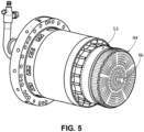
- Fig. 5 shows an alternative embodiment of a fuel nozzle assembly 53 with the addition of a central liquid fuel nozzle 96.
- Fig. 6 shows an aft plate removal tool 100 as may be described herein.
- an inner aft plate removal tool 105 is shown.
- the inner aft plate removal tool 105 is used within the combustor 25 to remove the aft plate 78 and the inner cap assembly 94.
- the inner aft plate removal tool 105 may be used to recontour and remove the aft plate 78 without damaging any of the micromixer tubes 92.
- the inner aft plate removal tool 105 may be used with the fuel nozzle assembly 53 of Fig. 3 .
- the inner aft plate removal tool 105 may include a base plate 110 with a base plate aperture 120, a threaded insert 130 positioned within the base plate aperture 120, and a threaded rod 140 extending through the threaded insert 130.
- the thread rod 140 may have a replaceable tip 150 on an aft end thereof.
- the replaceable tip 150 may be made out of Delrin (polyoxymethylene) or similar materials to protect against wear due to frictional contact with the aft plate 78.
- the threaded rod 140 also may have an outer sleeve 160 to protect the adjacent micromixer tubes 92.
- the threaded rod 140 may have any convenient length and other dimensions.
- the base plate 110 may have a number of attachment apertures 170 therein. A number of mounting bolts 180 and the like may be used to attach the inner aft plate removal tool 105 to the end cover 58 of the combustor 25. Other components and other configurations may be used herein.
- Figs. 7 and 8 show the inner aft plate removal tool 105 in use.
- the inner aft plate removal tool 105 may be inserted within the central passage 86 of the combustor 25.
- the inner aft plate removal tool 105 may be advanced therein until the replaceable tip 150 contacts the aft plate 78.
- the base plate 110 may be attached to the end cover 48 by attaching the mounting bolts 180.
- the threaded rod 140 may be rotated to advance. Specifically, the threaded rod 140 is rotated within the threaded insert 130 of the base plate 110.
- the threaded rod 140 As the threaded rod 140 advances in contact with the aft plate 78, the threaded rod 140 flattens any deformation in the aft plate 78. As the aft plate 78 flattens, the aft plate 78 and the inner cap assembly 94 begin to separate from the micromixer tubes 92. The threaded rod 140 continues to advance until the aft plate 78 and the inner cap assembly 94 is completely pushed off of the micromixer tubes 92. The advance of the threaded rod 140 thus allows the aft plate 78 and the inner cap assembly 94 to slide freely off of the micromixer tubes 92 without any damage thereto. The threaded rod 140 them may be rotated in the opposite direction and the inner aft plate removal tool 105 may be unattached from the end cover 58. The inner aft plate removal tool 105 may be withdrawn from the combustor 25.
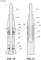
- Figs. 9-11 show a further embodiment of the aft plate removal tool 100.
- an outer aft plate removal tool 200 is shown.
- the outer aft plate removal tool 200 is used from outside the combustor 25 to remove the aft plate 78 and the inner cap assembly 94.
- the outer aft plate removal tool 200 may be used with the fuel nozzle assembly 95 of Fig. 5 once the central liquid fuel nozzle 96 has been removed.
- the outer aft plate removal tool 200 may include a central screw 210.
- a lower housing 220 and an upper housing 230 may be mounted on the central screw 210.
- the central screw 210 may be fixed within the lower housing 220.
- the lower housing 220 also may have a pair of slide rods 240 fixed therein. Each slide rod 240 may have a slide rod bearing 245 thereon.
- the upper housing 230 may be rotatably mounted onto the central screw 210.
- the upper housing 230 also may have a complementary slide rod bore 250 formed therein.
- the upper housing 230 may be rotatable with respect to the lower housing 220 along the central screw 210 and the slide rods 240.
- the lower housing 220 may have a pair of lower feet 260 attached thereto. Each of the pair of lower feet 260 may be attached to the lower housing 220 by a lower pin 270. Each of the pair of lower feet 260 may be spring loaded via a lower spring 280. The lower feet 260 may be rotatable via the lower springs 280.
- the upper housing 230 may have a pair of upper feet 290 attached thereto. Each of the pair of upper feet 290 may be attached to the upper housing 230 by an upper pin 300. Each of the pair of upper feet 290 may be spring loaded via an upper spring 310. The upper feet 290 may be rotatable via the upper springs 310. Each of the upper feet 290 may have an upper foot pad 320 thereon.
- the upper foot pads 320 may be made out of Delrin (polyoxymethylene) or similar materials to protect against frictional contact with the aft plate 78.
- the lower feet 260 and the upper feet 290 may be retracted within the housings 220, 230 via a set screw 330 and the like. Other components and other configurations may be used herein.
- the lower feet 260 and the upper feet 290 may be retracted via the set screw 330.
- the outer aft plate removal tool 200 may be inserted within the center passage 86 of the aft plate 78 and the inner cap assembly 94. Once clear of the aft plate 78, the lower feet 260 and the upper feet 290 may be extended.
- the lower feet 260 may be positioned about the downstream plate 74 and the upper feet 290 may be positioned beneath the aft plate 78.
- the upper housing 230 may be rotated and may move upward against the aft plate 78. As the upper housing 230 advances in contact with the aft plate 78, the upper feet 290 may flatten any deformation in the aft plate 78.
- the aft plate 78 and the inner cap assembly 94 begin to separate from the micromixer tubes 92.
- the upper housing 230 and the upper feet 290 continue to advance until the aft plate 78 and the inner cap assembly 94 is completely pushed off of the micromixer tubes 92.
Landscapes
- Engineering & Computer Science (AREA)
- Mechanical Engineering (AREA)
- Chemical & Material Sciences (AREA)
- Combustion & Propulsion (AREA)
- General Engineering & Computer Science (AREA)
- Gas Burners (AREA)
Abstract
The present application provides an aft plate removal tool (100) for servicing a combustor (25), the combustor (25) including an aft plate (78) with a central passage (86) and a number of tubes (92) extending through the aft plate (78). The aft plate removal tool (100) includes a central screw (210), a lower housing (220) attached to the central screw (210), the lower housing (220) including a number of spring loaded lower housing feet (260) and an upper housing (230) attached to the center screw (210), the upper housing (230) including a number of spring loaded upper housing feet (290). The aft plate removal tool (100) is inserted through the central passage (86) of the aft plate (78) such that rotation of the upper housing (230) advances the spring loaded upper housing feet (290) against the aft plate (78) until the spring loaded upper housing feet (290) push the aft plate (78) off of the tubes (92).
Description
- The present application and the resultant patent relate generally to gas turbine engines and more particularly relate to improved methods and tooling to remove safely an aft inner cap plate from a micromixer headend of a combustor during repair and replacement.
- A gas turbine engine conventionally includes a compressor for compressing ambient air and a number of combustors for mixing the flow of air with a flow of fuel to generate hot combustion gases. A turbine receives the flow of hot combustion gases and extracts energy therefrom for powering the compressor and for producing output power for an external load such as an electrical generator and the like. The combustors may be annularly arranged between the compressor and the turbine.
- The combustors may include one or more bundled tube fuel injectors that extend downstream from an end cover. The bundled tube fuel injectors generally include a number of pre-mix or micromixer tubes. The micromixer tubes extend generally parallel to one another through the bundled tube fuel injector. An outer shroud extends circumferentially around the micromixer tubes and an aft plate extends radially and circumferentially across a downstream end thereof adjacent to a combustion chamber or zone defined within the combustor. A tube tip portion of each micromixer tube extends through the aft plate such that an outlet of each tube is downstream from a hot side surface of the aft plate, thus providing for fluid communication into the combustion chamber or zone.
- Each of the micromixer tubes extends generally axially through a fuel plenum and a cooling air plenum. Compressed air is routed through inlets of each of the micromixer tubes upstream from the fuel plenum. Fuel is injected into the micromixer tubes through one or more fuel ports defined within each of the tubes. The fuel and compressed air mix inside the micromixer tubes before flowing out of the outlet of each of the tubes and into the combustion chamber or zone for combustion.
- During operation of the combustor, the downstream or end portion of each micromixer tubes is exposed to extreme temperatures due to the proximity to the combustion chamber and/or the combustion flame. Likewise, the aft plate through which the micromixer tubes extend also may deform or dish due to the harsh conditions. Over time, various factors including thermal stress, mechanical fatigue, and combustion dynamics or vibrations may adversely affect the operating condition of the bundled tube fuel injectors, thus requiring scheduled inspection and in some cases repair or refurbishment of the components therein. Specifically, the dishing of the aft plate and the close fit may cause the micromixer tubes that run through the aft plate to bind. Removing the aft plate by moving it to the right, however, may damage the fuel injectors.
- The present application and the resultant patent thus provide an aft plate removal tool for servicing a combustor. The combustor includes an aft plate with a central passage and a number of tubes extending through the aft plate. The aft plate removal tool includes a central screw, a lower housing attached to the central screw, the lower housing including a number of spring loaded lower housing feet, and an upper housing attached to the center screw, the upper housing including a number of spring loaded upper housing feet. The aft plate removal tool is inserted through the central passage of the aft plate such that rotation of the upper housing advances the spring loaded upper housing feet against the aft plate until the spring loaded upper housing feet push the aft plate off of the tubes.
- The present application and the resultant patent further provide a method of removing an aft plate from a number of tubes of a combustor. The method may include the steps of inserting an aft plate removal tool through the aft plate, releasing a number of feet of the aft plate removal tool, rotating an upper housing of the aft plate removal tool to advance a number of the feet into contact with the aft plate, rotating further the upper housing to deform the aft plate, and rotating further the upper housing to push the aft plate off of the tubes.
- These and other features and improvements of this application and the resultant patent will become apparent to one of ordinary skill in the art upon review of the following detailed description when taken in conjunction with the several drawings and the appended claims.
-
-
Fig. 1 is a schematic diagram of a gas turbine engine including a compressor, a combustor, a turbine, and an external load. -
Fig. 2 is a schematic diagram of a combustor that may be used with the gas turbine engine ofFig. 1 . -
Fig. 3 is a perspective view of a fuel nozzle assembly of the combustor ofFig. 2 . -
Fig. 4 is a schematic diagram of a fuel injector that may be used with the combustor ofFig. 2 . -
Fig. 5 is a perspective view of an alternative embodiment of a fuel nozzle assembly that may be used with the combustor ofFig. 2 -
Fig. 6 is a perspective view of an example of an aft plate removal tool as may be described herein. -
Fig. 7 is a partial sectional view of a combustor with the aft plate removal tool ofFig. 6 installed therein. -
Fig. 8 is a partial perspective view of an end plate of a combustor with the aft plate removal tool installed therein. -
Fig. 9 is a plan view of an alternative embodiment of an aft plate removal tool as may be described herein. -
Fig. 10 is a sectional view of the aft plate removal tool ofFig. 9 . -
Fig. 11 is a further sectional view of the aft plate removal tool ofFig. 9 . - Referring now to the drawings, in which like numerals refer to like elements throughout the several views,
Fig. 1 shows a schematic diagram of agas turbine engine 10 as may be described herein. Thegas turbine engine 10 may include acompressor 15. Thecompressor 15 compresses an incoming flow ofair 20. Thecompressor 15 delivers the compressed flow ofair 20 to a number ofcombustor cans 25. The combustor cans 25 mix the compressed flow ofair 20 with a pressurized flow offuel 30 and ignite the mixture to create a flow ofhot combustion gases 35. Although only a single combustor can 25 is shown, thegas turbine engine 10 may include any number ofcombustor cans 25 positioned in a circumferential array and the like. Alternatively, thecombustor 25 may be an annular combustor. The flow ofcombustion gases 35 is in turn delivered to aturbine 40. The flow ofcombustion gases 35 drives theturbine 40 to produce mechanical work. The mechanical work produced in theturbine 40 drives thecompressor 15 via arotor shaft 45. Theturbine 40 and therotor shaft 45 also may drive anexternal load 50 such as an electrical generator and the like. - The
gas turbine engine 10 may use natural gas, various types of syngas, liquid fuels, and/or other types of fuels and blends thereof. Thegas turbine engine 10 may be any one of a number of different gas turbine engines offered by General Electric Company of Schenectady, New York, including, but not limited to, those such as a 7-series or a 9-series heavy duty gas turbine engine and the like. Thegas turbine engine 10 may be part of a simple cycle or a combined cycle power generation system or other types of generation systems. Thegas turbine engine 10 may have different configurations and may use other types of components. Other types of gas turbine engines also may be used herein. Multiple gas turbine engines, other types of turbines, and other types of power generation equipment also may be used herein together. -
Fig. 2 is a partial sectional view of thecombustor 25. Thecombustor 25 may incorporate a number offuel injectors 52 therein. Thefuel nozzles 52 may be combined in afuel nozzle assembly 53. In this example, thefuel injectors 52 may be bundled tube fuel injectors and the like. Thecombustor 25 is at least partially surrounded by anouter casing 54. Theouter casing 54 forms ahigh pressure plenum 56 around thecombustor 25. Thehigh pressure plenum 56 may be in fluid communication with thecompressor 15 or other source for supplying the flow ofair 20 to thecombustor 25. Anend cover 58 is coupled to theouter casing 54. Theend cover 58 may be in fluid communication with the flow offuel 30. - The
fuel injectors 52 extend downstream from theend cover 58. Thefuel injector 52 may be fluidly connected to theend cover 58 so as to receive the flow offuel 30. For example, afluid conduit 60 may provide for fluid communication between theend cover 58 and thefuel injector 52. One end of anannular liner 62 such as a combustion liner and/or a transition duct surrounds adownstream end 64 of thefuel injector 52 so as to at least partially define acombustion chamber 66. Theliner 62 defines ahot gas path 68 for directing thecombustion gases 35 from thecombustion chamber 66. - In operation, the flow of
air 20 is routed towards theend cover 58 where it reverses direction and flows through one or more of thefuel injectors 52. The flow offuel 30 is provided to thefuel injector 52 and the flow offuel 30 and the flow ofair 20 are premixed or combined within thefuel injector 52 before being injected into acombustion chamber 66 for combustion. -
Fig. 3 is a perspective view of thefuel injector assembly 53 whileFig. 4 is a sectional view of an example of thefuel injector 52 described above. Thefuel injector 52 generally includes afuel distribution module 70 that is in fluid communication with thefluid conduit 60. Thefuel distribution module 70 includes anupstream plate 72 that is axially separated from adownstream plate 74. Afuel plenum 76 may be defined between the upstream anddownstream plates fluid conduit 60 provides for the flow offuel 30 to thefuel plenum 76. - An
aft plate 78 is disposed at a downstream or aft end of thefuel injector 52. Theaft plate 78 extends radially outwardly and circumferentially across the aft end with respect to an axial centerline. Theaft plate 78 at least partially defines a number oftube tip passages 82 that extend generally axially therethrough. Animpingement plate 84 is disposed upstream from theaft plate 78. Theimpingement plate 84 may be welded, brazed or otherwise coupled to theaft plate 78. Theaft plate 78 and/or theimpingement plate 84 may at least partially define acenter passage 86 that extends generally axially therethrough. Afluid cartridge insert 88 may be coupled to theaft plate 78 at thecenter passage 86. Theaft plate 78, theimpingement plate 84, and the related components herein may be described as aninner cap assembly 94. - The
fuel injector 52 includes amicromixer tube bundle 90. Themicromixer tube bundle 90 includes a number of micromixer (or pre-mixer) tubes 92 that extend generally parallel to one another along or parallel to the axial centerline of thefuel injector 52. The micromixer tubes 92 extend downstream from thefuel plenum 76 towards theaft plate 78 and/or thecombustion chamber 66. A portion of the micromixer tubes 92 extends through theaft plate 78. Each micromixer tube 92 is generally aligned with the correspondingtube tip passage 82. The micromixer tubes 92 may be arranged in a number of rows or otherwise. Similarly,Fig. 5 shows an alternative embodiment of afuel nozzle assembly 53 with the addition of a centralliquid fuel nozzle 96. -
Fig. 6 shows an aft plate removal tool 100 as may be described herein. In this example, an inner aft plate removal tool 105 is shown. As the name implies, the inner aft plate removal tool 105 is used within thecombustor 25 to remove theaft plate 78 and theinner cap assembly 94. Specifically, the inner aft plate removal tool 105 may be used to recontour and remove theaft plate 78 without damaging any of the micromixer tubes 92. The inner aft plate removal tool 105 may be used with thefuel nozzle assembly 53 ofFig. 3 . - The inner aft plate removal tool 105 may include a
base plate 110 with abase plate aperture 120, a threadedinsert 130 positioned within thebase plate aperture 120, and a threadedrod 140 extending through the threadedinsert 130. Thethread rod 140 may have areplaceable tip 150 on an aft end thereof. Thereplaceable tip 150 may be made out of Delrin (polyoxymethylene) or similar materials to protect against wear due to frictional contact with theaft plate 78. The threadedrod 140 also may have anouter sleeve 160 to protect the adjacent micromixer tubes 92. The threadedrod 140 may have any convenient length and other dimensions. Thebase plate 110 may have a number ofattachment apertures 170 therein. A number of mountingbolts 180 and the like may be used to attach the inner aft plate removal tool 105 to theend cover 58 of thecombustor 25. Other components and other configurations may be used herein. -
Figs. 7 and8 show the inner aft plate removal tool 105 in use. The inner aft plate removal tool 105 may be inserted within thecentral passage 86 of thecombustor 25. The inner aft plate removal tool 105 may be advanced therein until thereplaceable tip 150 contacts theaft plate 78. Thebase plate 110 may be attached to the end cover 48 by attaching the mountingbolts 180. Once firmly secured in place, the threadedrod 140 may be rotated to advance. Specifically, the threadedrod 140 is rotated within the threadedinsert 130 of thebase plate 110. - As the threaded
rod 140 advances in contact with theaft plate 78, the threadedrod 140 flattens any deformation in theaft plate 78. As theaft plate 78 flattens, theaft plate 78 and theinner cap assembly 94 begin to separate from the micromixer tubes 92. The threadedrod 140 continues to advance until theaft plate 78 and theinner cap assembly 94 is completely pushed off of the micromixer tubes 92. The advance of the threadedrod 140 thus allows theaft plate 78 and theinner cap assembly 94 to slide freely off of the micromixer tubes 92 without any damage thereto. The threadedrod 140 them may be rotated in the opposite direction and the inner aft plate removal tool 105 may be unattached from theend cover 58. The inner aft plate removal tool 105 may be withdrawn from thecombustor 25. -
Figs. 9-11 show a further embodiment of the aft plate removal tool 100. In this example, an outer aft plate removal tool 200 is shown. As the name implies, the outer aft plate removal tool 200 is used from outside thecombustor 25 to remove theaft plate 78 and theinner cap assembly 94. The outer aft plate removal tool 200 may be used with the fuel nozzle assembly 95 ofFig. 5 once the centralliquid fuel nozzle 96 has been removed. - The outer aft plate removal tool 200 may include a
central screw 210. Alower housing 220 and anupper housing 230 may be mounted on thecentral screw 210. Thecentral screw 210 may be fixed within thelower housing 220. Thelower housing 220 also may have a pair ofslide rods 240 fixed therein. Eachslide rod 240 may have a slide rod bearing 245 thereon. Theupper housing 230 may be rotatably mounted onto thecentral screw 210. Theupper housing 230 also may have a complementary slide rod bore 250 formed therein. Theupper housing 230 may be rotatable with respect to thelower housing 220 along thecentral screw 210 and theslide rods 240. - The
lower housing 220 may have a pair oflower feet 260 attached thereto. Each of the pair oflower feet 260 may be attached to thelower housing 220 by alower pin 270. Each of the pair oflower feet 260 may be spring loaded via alower spring 280. Thelower feet 260 may be rotatable via the lower springs 280. Likewise, theupper housing 230 may have a pair ofupper feet 290 attached thereto. Each of the pair ofupper feet 290 may be attached to theupper housing 230 by anupper pin 300. Each of the pair ofupper feet 290 may be spring loaded via anupper spring 310. Theupper feet 290 may be rotatable via the upper springs 310. Each of theupper feet 290 may have anupper foot pad 320 thereon. Theupper foot pads 320 may be made out of Delrin (polyoxymethylene) or similar materials to protect against frictional contact with theaft plate 78. Thelower feet 260 and theupper feet 290 may be retracted within thehousings set screw 330 and the like. Other components and other configurations may be used herein. - In use, the
lower feet 260 and theupper feet 290 may be retracted via theset screw 330. The outer aft plate removal tool 200 may be inserted within thecenter passage 86 of theaft plate 78 and theinner cap assembly 94. Once clear of theaft plate 78, thelower feet 260 and theupper feet 290 may be extended. Thelower feet 260 may be positioned about thedownstream plate 74 and theupper feet 290 may be positioned beneath theaft plate 78. Theupper housing 230 may be rotated and may move upward against theaft plate 78. As theupper housing 230 advances in contact with theaft plate 78, theupper feet 290 may flatten any deformation in theaft plate 78. As theaft plate 78 flattens, theaft plate 78 and theinner cap assembly 94 begin to separate from the micromixer tubes 92. Theupper housing 230 and theupper feet 290 continue to advance until theaft plate 78 and theinner cap assembly 94 is completely pushed off of the micromixer tubes 92. - The advance of the
upper housing 230 thus allows theaft plate 78 and theinner cap assembly 94 to slide freely off of the micromixer tubes 92. Theaft plate 78 and the outer aft plate removal tool 200 then may be withdrawn from thecombustor 25. The outer aft plate removal tool 200 thus provides the safe removal of theaft plate 78 and theinner cap assembly 94 from the micromixer tubes 92 in a fast and efficient manner. - It should be apparent that the foregoing relates only to certain embodiments of the present application and resultant patent. Numerous changes and modifications may be made herein by one of ordinary skill in the art without departing from the general spirit and scope of the invention as defined by the following claims and the equivalents thereof.
- Further aspects of the invention are provided by the subject matter of the following clauses:
- 1. An aft plate removal tool for servicing a combustor, the combustor comprising an aft plate with a central passage and a plurality of tubes extending through the aft plate; the aft plate removal tool comprising: a central screw; a lower housing attached to the central screw, the lower housing comprising a plurality of spring loaded lower housing feet; and an upper housing attached to the center screw, the upper housing comprising a plurality of spring loaded upper housing feet; wherein the aft plate removal tool is inserted through the central passage of the aft plate; and wherein rotation of the upper housing advances the plurality of spring loaded upper housing feet against the aft plate until the plurality of spring loaded upper housing feet push the aft plate off of the plurality of tubes.
- 2. The aft plate removal tool of any preceding clause, wherein the central screw is fixed within the lower housing.
- 3. The aft plate removal tool of any preceding clause, wherein the upper housing rotates about the central screw.
- 4. The aft plate removal tool of any preceding clause, wherein the plurality of spring loaded upper housing feet comprises pads thereon.
- 5. The aft plate removal tool of any preceding clause, wherein the pads comprise a polyoxymethylene material.
- 6. The aft plate removal tool of any preceding clause, wherein the lower housing comprises a slide rod fixed therein and wherein the upper housing rotates about the slide rod.
- 7. The aft plate removal tool of any preceding clause, wherein the slide rod comprises a bearing thereon.
- 8. The aft plate removal tool of any preceding clause, wherein the plurality of spring loaded lower housing feet comprises a pair of spring loaded lower housing feet and wherein the plurality of spring loaded upper housing feet comprises a pair of spring loaded upper housing feet.
- 9. A method of removing an aft plate from a plurality of tubes of a combustor, comprising: inserting an aft plate removal tool through the aft plate; releasing a plurality of feet of the aft plate removal tool; rotating an upper housing of the aft plate removal tool to advance a number of the plurality of feet into contact with the aft plate; rotating further the upper housing to deform the aft plate; and rotating further the upper housing to push the aft plate off of the plurality of tubes.
- 10. The method of any preceding clause, wherein the aft plate removal tool is inserted through a central passage of the aft plate.
- 11. The method of any preceding clause, wherein a lower housing and the upper housing are attached to a central screw.
- 12. The method of any preceding clause, wherein the central screw is fixed within the lower housing.
- 13. The method of any preceding clause, wherein the upper housing rotates about the central screw.
- 14. The method of any preceding clause, wherein the plurality of feet comprises a plurality of spring loaded feet.
- 15. The method of any preceding clause, wherein the plurality of feet comprises a pair of upper housing feet and a pair of lower housing feet.
- 16. The method of any preceding clause, wherein the pair of upper housing feet comprises pads thereon.
- 17. The method of any preceding clause, wherein the pads comprise a polyoxymethylene material.
- 18. The method of any preceding clause, wherein the lower housing comprises a slide rod fixed therein and wherein the upper housing rotates about the slide rod.
- 19. The method of any preceding clause, wherein the slide rod comprises a bearing thereon.
Claims (15)
- An aft plate removal tool (100) for servicing a combustor (25), the combustor (25) comprising an aft plate (78) with a central passage (86) and a plurality of tubes (92) extending through the aft plate (78); the aft plate removal tool (100) comprising:a central screw (210);a lower housing (220) attached to the central screw (210), the lower housing (220) comprising a plurality of spring loaded lower housing feet (260); andan upper housing (230) attached to the center screw (210), the upper housing (230) comprising a plurality of spring loaded upper housing feet (290);wherein the aft plate removal tool (100) is inserted through the central passage (86) of the aft plate (78); andwherein rotation of the upper housing (230) advances the plurality of spring loaded upper housing feet (290) against the aft plate (78) until the plurality of spring loaded upper housing feet (290) push the aft plate (78) off of the plurality of tubes (92).
- The aft plate removal tool (100) of claim 1, wherein the central screw (210) is fixed within the lower housing (220).
- The aft plate removal tool (100) of claim 1, wherein the upper housing (230) rotates about the central screw (210).
- The aft plate removal tool (100) of claim 1, wherein the plurality of spring loaded upper housing feet (270) comprises pads (320) thereon.
- The aft plate removal tool (100) of claim 4, wherein the pads (320) comprise a polyoxymethylene material.
- The aft plate removal tool (100) of claim 1, wherein the lower housing (220) comprises a slide rod (240) fixed therein and wherein the upper housing (230) rotates about the slide rod (240).
- The aft plate removal tool (100) of claim 6, wherein the slide rod (240) comprises a bearing (245) thereon.
- The aft plate removal tool (100) of claim 1, wherein the plurality of spring loaded lower housing feet (260) comprises a pair of spring loaded lower housing feet (260) and wherein the plurality of spring loaded upper housing feet (290) comprises a pair of spring loaded upper housing feet (290).
- A method of removing an aft plate (78) from a plurality of tubes (92) of a combustor (25), comprising:inserting an aft plate removal tool (100) through the aft plate (78);releasing a plurality of feet (260, 290) of the aft plate removal tool;rotating an upper housing (230) of the aft plate removal tool (100) to advance a number of the plurality of feet (260, 290) into contact with the aft plate (78);rotating further the upper housing (230) to deform the aft plate (78); androtating further the upper housing (230) to push the aft plate (78) off of the plurality of tubes (92).
- The method of claim 9, wherein the aft plate removal tool (100) is inserted through a central passage (86) of the aft plate (78).
- The method of claim 9, wherein a lower housing (220) and the upper housing (230) are attached to a central screw (210).
- The method of claim 11, wherein the central screw (210) is fixed within the lower housing (220).
- The method of claim 11, wherein the upper housing (230) rotates about the central screw (210).
- The method of claim 9, wherein the plurality of feet (260, 290) comprises a plurality of spring loaded feet.
- The method of claim 9, wherein the plurality of feet (260, 290) comprises a pair of lower housing feet (260) and a pair of upper housing feet (290).
Applications Claiming Priority (1)
| Application Number | Priority Date | Filing Date | Title |
|---|---|---|---|
| US18/479,218 US12103148B1 (en) | 2023-10-02 | 2023-10-02 | Aft inner cap plate removal method and tooling for a combustor with micromixer tubes |
Publications (1)
| Publication Number | Publication Date |
|---|---|
| EP4534909A1 true EP4534909A1 (en) | 2025-04-09 |
Family
ID=92712275
Family Applications (1)
| Application Number | Title | Priority Date | Filing Date |
|---|---|---|---|
| EP24199187.6A Pending EP4534909A1 (en) | 2023-10-02 | 2024-09-09 | Aft inner cap plate removal method and tooling for a combustor with micromixer tubes |
Country Status (5)
| Country | Link |
|---|---|
| US (2) | US12103148B1 (en) |
| EP (1) | EP4534909A1 (en) |
| JP (1) | JP2025062574A (en) |
| KR (1) | KR20250048525A (en) |
| CN (1) | CN119748088A (en) |
Families Citing this family (1)
| Publication number | Priority date | Publication date | Assignee | Title |
|---|---|---|---|---|
| US12434362B2 (en) * | 2023-10-02 | 2025-10-07 | Ge Infrastructure Technology Llc | Aft inner cap plate removal method and tooling for a combustor with micromixer tubes |
Citations (3)
| Publication number | Priority date | Publication date | Assignee | Title |
|---|---|---|---|---|
| US20150165568A1 (en) * | 2013-12-13 | 2015-06-18 | General Electric Company | Method for repairing a bundled tube fuel injector |
| US9422827B2 (en) * | 2013-08-23 | 2016-08-23 | General Electric Company | Apparatus and method for servicing gas turbine engines |
| CN210210213U (en) * | 2019-05-29 | 2020-03-31 | 福鞍控股有限公司 | Gas turbine's crossfire pipe assembly fixture |
Family Cites Families (18)
| Publication number | Priority date | Publication date | Assignee | Title |
|---|---|---|---|---|
| US1492877A (en) * | 1922-03-30 | 1924-05-06 | Bernard H Davis | Device for removing liners and valve seats of pumps |
| US2290427A (en) * | 1941-03-14 | 1942-07-21 | Samuel A Harrington | Bearing puller |
| US3535765A (en) * | 1967-11-29 | 1970-10-27 | William A Denehie | Valve seat extractor |
| US4009515A (en) * | 1974-12-09 | 1977-03-01 | Charles Racin | Disc brake piston puller |
| US5255435A (en) * | 1992-10-14 | 1993-10-26 | Shultz William E | Apparatus and method for removing bearings |
| US5379503A (en) * | 1993-05-10 | 1995-01-10 | Roy-Con Tool & Mfg., Inc. | Extraction tool for transmissions |
| WO2011060422A2 (en) * | 2009-11-16 | 2011-05-19 | Weir Spm, Inc. | Valve seat installation and retrieval tool |
| US9562687B2 (en) | 2013-02-06 | 2017-02-07 | General Electric Company | Variable volume combustor with an air bypass system |
| US9579779B1 (en) * | 2013-05-02 | 2017-02-28 | Jacob Hunter | Valve seat puller |
| US9528703B2 (en) | 2013-09-20 | 2016-12-27 | General Electric Company | Micro-mixer fuel plenum and methods for fuel tube installation |
| US20150167983A1 (en) | 2013-12-13 | 2015-06-18 | General Electric Company | Bundled tube fuel injector tube tip |
| US9664392B2 (en) | 2013-12-13 | 2017-05-30 | General Electric Company | Bundled tube fuel injector with outer shroud and outer band connection |
| US9423134B2 (en) | 2013-12-13 | 2016-08-23 | General Electric Company | Bundled tube fuel injector with a multi-configuration tube tip |
| US9423136B2 (en) | 2013-12-13 | 2016-08-23 | General Electric Company | Bundled tube fuel injector aft plate retention |
| US9400112B2 (en) | 2013-12-13 | 2016-07-26 | General Electric Company | Method for disassembling a bundled tube fuel injector |
| US9302380B2 (en) * | 2014-04-07 | 2016-04-05 | Samuel Weaver | Seat puller |
| US10690059B2 (en) | 2016-09-26 | 2020-06-23 | General Electric Company | Advanced seals with reduced corner leakage |
| US11525578B2 (en) | 2017-08-16 | 2022-12-13 | General Electric Company | Dynamics-mitigating adapter for bundled tube fuel nozzle |
-
2023
- 2023-10-02 US US18/479,218 patent/US12103148B1/en active Active
-
2024
- 2024-08-16 US US18/807,033 patent/US20250108493A1/en active Pending
- 2024-09-09 EP EP24199187.6A patent/EP4534909A1/en active Pending
- 2024-09-19 JP JP2024162195A patent/JP2025062574A/en active Pending
- 2024-09-23 CN CN202411326010.4A patent/CN119748088A/en active Pending
- 2024-10-02 KR KR1020240133613A patent/KR20250048525A/en active Pending
Patent Citations (3)
| Publication number | Priority date | Publication date | Assignee | Title |
|---|---|---|---|---|
| US9422827B2 (en) * | 2013-08-23 | 2016-08-23 | General Electric Company | Apparatus and method for servicing gas turbine engines |
| US20150165568A1 (en) * | 2013-12-13 | 2015-06-18 | General Electric Company | Method for repairing a bundled tube fuel injector |
| CN210210213U (en) * | 2019-05-29 | 2020-03-31 | 福鞍控股有限公司 | Gas turbine's crossfire pipe assembly fixture |
Also Published As
| Publication number | Publication date |
|---|---|
| CN119748088A (en) | 2025-04-04 |
| JP2025062574A (en) | 2025-04-14 |
| US20250108493A1 (en) | 2025-04-03 |
| US12103148B1 (en) | 2024-10-01 |
| KR20250048525A (en) | 2025-04-09 |
Similar Documents
| Publication | Publication Date | Title |
|---|---|---|
| US9400114B2 (en) | Combustor support assembly for mounting a combustion module of a gas turbine | |
| US10072847B2 (en) | Method for repairing a bundled tube fuel injector | |
| US9664392B2 (en) | Bundled tube fuel injector with outer shroud and outer band connection | |
| US10215413B2 (en) | Bundled tube fuel nozzle with vibration damping | |
| CN110857783B (en) | Combustor assemblies for turbines | |
| EP3312510A1 (en) | Combustor assembly with air shield for a radial fuel injector | |
| US20250108493A1 (en) | Aft inner cap plate removal method and tooling for a combustor with micromixer tubes | |
| US20170343216A1 (en) | Fuel Nozzle Assembly with Tube Damping | |
| US20140318139A1 (en) | Premixer assembly for gas turbine combustor | |
| US9157370B2 (en) | Burner assembly | |
| US12434362B2 (en) | Aft inner cap plate removal method and tooling for a combustor with micromixer tubes | |
| EP3961103B1 (en) | Methods of servicing a fuel nozzle tip | |
| EP3586061B1 (en) | Endcover assembly for a combustor | |
| CN116772238B (en) | Dome-guide connector cooling arrangement | |
| CN116928695A (en) | Annular dome assembly for a combustor | |
| BR102024019748A2 (en) | METHOD OF REMOVING THE INNER TRANSOM COVER PLATE AND TOOLS FOR A COMBUSTOR WITH MICROMIXER TUBES |
Legal Events
| Date | Code | Title | Description |
|---|---|---|---|
| PUAI | Public reference made under article 153(3) epc to a published international application that has entered the european phase |
Free format text: ORIGINAL CODE: 0009012 |
|
| STAA | Information on the status of an ep patent application or granted ep patent |
Free format text: STATUS: THE APPLICATION HAS BEEN PUBLISHED |
|
| AK | Designated contracting states |
Kind code of ref document: A1 Designated state(s): AL AT BE BG CH CY CZ DE DK EE ES FI FR GB GR HR HU IE IS IT LI LT LU LV MC ME MK MT NL NO PL PT RO RS SE SI SK SM TR |
|
| RAP3 | Party data changed (applicant data changed or rights of an application transferred) |
Owner name: GE VERNOVA TECHNOLOGY GMBH |
|
| STAA | Information on the status of an ep patent application or granted ep patent |
Free format text: STATUS: REQUEST FOR EXAMINATION WAS MADE |
|
| 17P | Request for examination filed |
Effective date: 20251007 |