EP4534874A1 - Axle assembly having a shift mechanism - Google Patents
Axle assembly having a shift mechanism Download PDFInfo
- Publication number
- EP4534874A1 EP4534874A1 EP24203562.4A EP24203562A EP4534874A1 EP 4534874 A1 EP4534874 A1 EP 4534874A1 EP 24203562 A EP24203562 A EP 24203562A EP 4534874 A1 EP4534874 A1 EP 4534874A1
- Authority
- EP
- European Patent Office
- Prior art keywords
- drive pinion
- axis
- linkage
- actuator
- shift collar
- Prior art date
- Legal status (The legal status is an assumption and is not a legal conclusion. Google has not performed a legal analysis and makes no representation as to the accuracy of the status listed.)
- Pending
Links
Images




Classifications
-
- B—PERFORMING OPERATIONS; TRANSPORTING
- B60—VEHICLES IN GENERAL
- B60K—ARRANGEMENT OR MOUNTING OF PROPULSION UNITS OR OF TRANSMISSIONS IN VEHICLES; ARRANGEMENT OR MOUNTING OF PLURAL DIVERSE PRIME-MOVERS IN VEHICLES; AUXILIARY DRIVES FOR VEHICLES; INSTRUMENTATION OR DASHBOARDS FOR VEHICLES; ARRANGEMENTS IN CONNECTION WITH COOLING, AIR INTAKE, GAS EXHAUST OR FUEL SUPPLY OF PROPULSION UNITS IN VEHICLES
- B60K1/00—Arrangement or mounting of electrical propulsion units
-
- B—PERFORMING OPERATIONS; TRANSPORTING
- B60—VEHICLES IN GENERAL
- B60K—ARRANGEMENT OR MOUNTING OF PROPULSION UNITS OR OF TRANSMISSIONS IN VEHICLES; ARRANGEMENT OR MOUNTING OF PLURAL DIVERSE PRIME-MOVERS IN VEHICLES; AUXILIARY DRIVES FOR VEHICLES; INSTRUMENTATION OR DASHBOARDS FOR VEHICLES; ARRANGEMENTS IN CONNECTION WITH COOLING, AIR INTAKE, GAS EXHAUST OR FUEL SUPPLY OF PROPULSION UNITS IN VEHICLES
- B60K17/00—Arrangement or mounting of transmissions in vehicles
- B60K17/04—Arrangement or mounting of transmissions in vehicles characterised by arrangement, location or kind of gearing
- B60K17/16—Arrangement or mounting of transmissions in vehicles characterised by arrangement, location or kind of gearing of differential gearing
- B60K17/165—Arrangement or mounting of transmissions in vehicles characterised by arrangement, location or kind of gearing of differential gearing provided between independent half axles
-
- F—MECHANICAL ENGINEERING; LIGHTING; HEATING; WEAPONS; BLASTING
- F16—ENGINEERING ELEMENTS AND UNITS; GENERAL MEASURES FOR PRODUCING AND MAINTAINING EFFECTIVE FUNCTIONING OF MACHINES OR INSTALLATIONS; THERMAL INSULATION IN GENERAL
- F16H—GEARING
- F16H3/00—Toothed gearings for conveying rotary motion with variable gear ratio or for reversing rotary motion
- F16H3/02—Toothed gearings for conveying rotary motion with variable gear ratio or for reversing rotary motion without gears having orbital motion
- F16H3/08—Toothed gearings for conveying rotary motion with variable gear ratio or for reversing rotary motion without gears having orbital motion exclusively or essentially with continuously meshing gears, that can be disengaged from their shafts
- F16H3/087—Toothed gearings for conveying rotary motion with variable gear ratio or for reversing rotary motion without gears having orbital motion exclusively or essentially with continuously meshing gears, that can be disengaged from their shafts characterised by the disposition of the gears
- F16H3/093—Toothed gearings for conveying rotary motion with variable gear ratio or for reversing rotary motion without gears having orbital motion exclusively or essentially with continuously meshing gears, that can be disengaged from their shafts characterised by the disposition of the gears with two or more countershafts
-
- F—MECHANICAL ENGINEERING; LIGHTING; HEATING; WEAPONS; BLASTING
- F16—ENGINEERING ELEMENTS AND UNITS; GENERAL MEASURES FOR PRODUCING AND MAINTAINING EFFECTIVE FUNCTIONING OF MACHINES OR INSTALLATIONS; THERMAL INSULATION IN GENERAL
- F16H—GEARING
- F16H3/00—Toothed gearings for conveying rotary motion with variable gear ratio or for reversing rotary motion
- F16H3/02—Toothed gearings for conveying rotary motion with variable gear ratio or for reversing rotary motion without gears having orbital motion
- F16H3/08—Toothed gearings for conveying rotary motion with variable gear ratio or for reversing rotary motion without gears having orbital motion exclusively or essentially with continuously meshing gears, that can be disengaged from their shafts
- F16H3/087—Toothed gearings for conveying rotary motion with variable gear ratio or for reversing rotary motion without gears having orbital motion exclusively or essentially with continuously meshing gears, that can be disengaged from their shafts characterised by the disposition of the gears
- F16H3/093—Toothed gearings for conveying rotary motion with variable gear ratio or for reversing rotary motion without gears having orbital motion exclusively or essentially with continuously meshing gears, that can be disengaged from their shafts characterised by the disposition of the gears with two or more countershafts
- F16H3/097—Toothed gearings for conveying rotary motion with variable gear ratio or for reversing rotary motion without gears having orbital motion exclusively or essentially with continuously meshing gears, that can be disengaged from their shafts characterised by the disposition of the gears with two or more countershafts the input and output shafts being aligned on the same axis
-
- F—MECHANICAL ENGINEERING; LIGHTING; HEATING; WEAPONS; BLASTING
- F16—ENGINEERING ELEMENTS AND UNITS; GENERAL MEASURES FOR PRODUCING AND MAINTAINING EFFECTIVE FUNCTIONING OF MACHINES OR INSTALLATIONS; THERMAL INSULATION IN GENERAL
- F16H—GEARING
- F16H63/00—Control outputs from the control unit to change-speed- or reversing-gearings for conveying rotary motion or to other devices than the final output mechanism
- F16H63/02—Final output mechanisms therefor; Actuating means for the final output mechanisms
- F16H63/30—Constructional features of the final output mechanisms
-
- B—PERFORMING OPERATIONS; TRANSPORTING
- B60—VEHICLES IN GENERAL
- B60K—ARRANGEMENT OR MOUNTING OF PROPULSION UNITS OR OF TRANSMISSIONS IN VEHICLES; ARRANGEMENT OR MOUNTING OF PLURAL DIVERSE PRIME-MOVERS IN VEHICLES; AUXILIARY DRIVES FOR VEHICLES; INSTRUMENTATION OR DASHBOARDS FOR VEHICLES; ARRANGEMENTS IN CONNECTION WITH COOLING, AIR INTAKE, GAS EXHAUST OR FUEL SUPPLY OF PROPULSION UNITS IN VEHICLES
- B60K17/00—Arrangement or mounting of transmissions in vehicles
- B60K17/04—Arrangement or mounting of transmissions in vehicles characterised by arrangement, location or kind of gearing
- B60K17/043—Transmission unit disposed in on near the vehicle wheel, or between the differential gear unit and the wheel
-
- B—PERFORMING OPERATIONS; TRANSPORTING
- B60—VEHICLES IN GENERAL
- B60K—ARRANGEMENT OR MOUNTING OF PROPULSION UNITS OR OF TRANSMISSIONS IN VEHICLES; ARRANGEMENT OR MOUNTING OF PLURAL DIVERSE PRIME-MOVERS IN VEHICLES; AUXILIARY DRIVES FOR VEHICLES; INSTRUMENTATION OR DASHBOARDS FOR VEHICLES; ARRANGEMENTS IN CONNECTION WITH COOLING, AIR INTAKE, GAS EXHAUST OR FUEL SUPPLY OF PROPULSION UNITS IN VEHICLES
- B60K1/00—Arrangement or mounting of electrical propulsion units
- B60K2001/001—Arrangement or mounting of electrical propulsion units one motor mounted on a propulsion axle for rotating right and left wheels of this axle
-
- F—MECHANICAL ENGINEERING; LIGHTING; HEATING; WEAPONS; BLASTING
- F16—ENGINEERING ELEMENTS AND UNITS; GENERAL MEASURES FOR PRODUCING AND MAINTAINING EFFECTIVE FUNCTIONING OF MACHINES OR INSTALLATIONS; THERMAL INSULATION IN GENERAL
- F16H—GEARING
- F16H63/00—Control outputs from the control unit to change-speed- or reversing-gearings for conveying rotary motion or to other devices than the final output mechanism
- F16H63/02—Final output mechanisms therefor; Actuating means for the final output mechanisms
- F16H63/30—Constructional features of the final output mechanisms
- F16H2063/3093—Final output elements, i.e. the final elements to establish gear ratio, e.g. coupling sleeves or other means establishing coupling to shaft
- F16H2063/3096—Sliding keys as final output elements; Details thereof
-
- F—MECHANICAL ENGINEERING; LIGHTING; HEATING; WEAPONS; BLASTING
- F16—ENGINEERING ELEMENTS AND UNITS; GENERAL MEASURES FOR PRODUCING AND MAINTAINING EFFECTIVE FUNCTIONING OF MACHINES OR INSTALLATIONS; THERMAL INSULATION IN GENERAL
- F16H—GEARING
- F16H2200/00—Transmissions for multiple ratios
- F16H2200/0021—Transmissions for multiple ratios specially adapted for electric vehicles
-
- F—MECHANICAL ENGINEERING; LIGHTING; HEATING; WEAPONS; BLASTING
- F16—ENGINEERING ELEMENTS AND UNITS; GENERAL MEASURES FOR PRODUCING AND MAINTAINING EFFECTIVE FUNCTIONING OF MACHINES OR INSTALLATIONS; THERMAL INSULATION IN GENERAL
- F16H—GEARING
- F16H2200/00—Transmissions for multiple ratios
- F16H2200/003—Transmissions for multiple ratios characterised by the number of forward speeds
- F16H2200/0039—Transmissions for multiple ratios characterised by the number of forward speeds the gear ratios comprising three forward speeds
-
- F—MECHANICAL ENGINEERING; LIGHTING; HEATING; WEAPONS; BLASTING
- F16—ENGINEERING ELEMENTS AND UNITS; GENERAL MEASURES FOR PRODUCING AND MAINTAINING EFFECTIVE FUNCTIONING OF MACHINES OR INSTALLATIONS; THERMAL INSULATION IN GENERAL
- F16H—GEARING
- F16H3/00—Toothed gearings for conveying rotary motion with variable gear ratio or for reversing rotary motion
- F16H3/02—Toothed gearings for conveying rotary motion with variable gear ratio or for reversing rotary motion without gears having orbital motion
- F16H3/08—Toothed gearings for conveying rotary motion with variable gear ratio or for reversing rotary motion without gears having orbital motion exclusively or essentially with continuously meshing gears, that can be disengaged from their shafts
- F16H3/087—Toothed gearings for conveying rotary motion with variable gear ratio or for reversing rotary motion without gears having orbital motion exclusively or essentially with continuously meshing gears, that can be disengaged from their shafts characterised by the disposition of the gears
- F16H3/093—Toothed gearings for conveying rotary motion with variable gear ratio or for reversing rotary motion without gears having orbital motion exclusively or essentially with continuously meshing gears, that can be disengaged from their shafts characterised by the disposition of the gears with two or more countershafts
- F16H3/095—Toothed gearings for conveying rotary motion with variable gear ratio or for reversing rotary motion without gears having orbital motion exclusively or essentially with continuously meshing gears, that can be disengaged from their shafts characterised by the disposition of the gears with two or more countershafts with means for ensuring an even distribution of torque between the countershafts
Definitions
- the invention relates to an axle assembly.
- the axle assembly includes a drive pinion, a transmission, and a shift mechanism.
- the drive pinion is rotatable about an axis.
- the drive pinion has a drive pinion hole.
- the drive pinion hole extends along the axis.
- the drive pinion hole extends from a first end of the drive pinion toward a second end of the drive pinion.
- the second end of the drive pinion is disposed opposite the first end.
- the transmission comprises a set of gears.
- the shift mechanism includes a shift collar, a linkage, and an actuator.
- the shift collar is rotatable about the axis with the drive pinion.
- the shift collar is moveable along the axis with respect to the drive pinion.
- the linkage is coupled to the shift collar.
- the linkage is received in the drive pinion hole of the drive pinion.
- the actuator is coupled to the linkage.
- the actuator is configured to move the linkage and the
- the drive pinion may include a drive pinion extension.
- the drive pinion extension may be rotatable about the axis.
- the shift collar may be disposed on the drive pinion extension.
- the linkage may be received inside the drive pinion extension.
- the drive pinion extension may have a slot.
- the slot may extend in an axial direction with respect to the axis.
- a fastener may be received in the slot.
- the fastener may couple the linkage to the shift collar.
- the fastener may be fixedly coupled to the linkage and the shift collar.
- the fastener may be moveable in the slot in the axial direction.
- the linkage, the fastener, and the shift collar may move along the axis in a first direction when the actuator moves the shift collar toward the actuator.
- the linkage, the fastener, and the shift collar may move along the axis in a second direction that is disposed opposite the first direction when the actuator moves the shift collar away from the actuator.
- the axle assembly may include an end cover.
- the end cover may be disposed at an end of the axle assembly.
- the end cover may define a pocket.
- a support bearing may be received inside the pocket.
- the support bearing may rotatably support the drive pinion.
- the fastener may be received in the pocket.
- the axle assembly may include an axle housing and a differential carrier.
- the axle housing and the differential carrier may cooperate to define an internal cavity.
- the differential assembly may be received inside the internal cavity.
- the actuator may be received inside the internal cavity.
- the actuator may be mounted to the differential carrier.
- the actuator may be mounted to the axle housing.
- the actuator may be positioned further from the drive pinion than the differential axis is positioned from the drive pinion.
- the drive pinion may be rotatably coupled to the linkage.
- the linkage may be rotatable about the axis with the drive pinion.
- the linkage may be moveable along the axis with respect to the drive pinion.
- the drive pinion may be rotatably coupled to the linkage in the drive pinion hole.
- the drive pinion and the linkage may be rotatably coupled with mating splines.
- a support shaft may extend along the axis.
- the support shaft may be encircled by the linkage.
- the support shaft may be encircled by the shift collar.
- the support shaft may be rotatable about the axis.
- the linkage may be rotatable about the axis with the support shaft.
- first, second, etc. are, in some instances, used herein to describe various elements, these elements should not be limited by these terms. These terms are only used to distinguish one element from another. For example, a first element could be termed a second element, and similarly a second element could be termed a first element without departing from the scope of the various described embodiments. The first element and the second element are both elements, but they are not the same element.
- the axle assembly 10 is a drive axle assembly.
- a drive axle assembly is configured to provide torque to one or more wheel assemblies.
- a wheel assembly may be rotatably supported on the axle assembly 10.
- a wheel assembly may include a tire disposed on a wheel.
- the wheel may be mounted to a wheel hub that may be rotatable about a wheel axis.
- the wheel hub may be rotatably disposed on the axle assembly 10.
- the axle housing 40 may receive and support the axle shafts 24.
- the axle housing 40 may include a center portion 50 and at least one arm portion 52.
- the center portion 50 may be disposed proximate the center of the axle housing 40.
- the center portion 50 may help define an internal cavity 54 that may receive the differential assembly 22.
- the differential carrier 42 is configured to be mounted to the axle housing 40.
- the differential carrier 42 may be mounted to the center portion 50 of the axle housing 40.
- the differential assembly 22 may be rotatably supported on the differential carrier 42.
- the differential carrier 42 and the axle housing 40 may cooperate to define the internal cavity 54.
- the electric motor housing 44 may extend around or encircle the electric motor 26. In some configurations, the electric motor housing 44 extends between the differential carrier 42 and the transmission housing 46.
- the transmission housing 46 may extend around or encircle the transmission 28. In some configurations, the transmission housing 46 extends between the electric motor housing 44 and the end cover 48.
- the end cover 48 may be disposed at an end of the housing assembly 20.
- the end cover 48 may be mounted to an end of the transmission housing 46 that faces away from the differential assembly 22.
- the end cover 48 may define a pocket 56, which is best shown in Figure 2 .
- the pocket 58 may be disposed along an axis 80 about which the drive pinion 30 is rotatable as will be discussed in more detail below.
- the differential assembly 22 is disposed in the housing assembly 20.
- the differential assembly 22 may be disposed in the internal cavity 54.
- the differential assembly 22, which may also be called an axle differential, may transmit torque to the axle shafts 24 of the axle assembly 10 and permit the axle shafts 24 and wheel assemblies to rotate at different velocities in a manner known by those skilled in the art.
- the differential assembly 22 may have a ring gear 60 that may be fixedly mounted to a differential case.
- the ring gear 60 and the differential case are rotatable about a differential axis 62.
- the differential case may receive differential gears that may be operatively connected to the axle shafts 24.
- the axle shafts 24 are configured to transmit torque between the differential assembly 22 and a corresponding wheel hub.
- two axle shafts 24 may be provided such that each axle shaft 24 extends through a different arm portion 52 of axle housing 40.
- the axle shafts 24 may be rotatable about a wheel axis.
- the wheel axis may be the same as the differential axis 62 or may differ from the differential axis 62.
- the electric motor 26 is configured to provide torque, such as propulsion torque or regenerative braking torque.
- Propulsion torque may be used to propel the vehicle, such as in a forward or backward direction.
- Propulsion torque may also be used to hold the vehicle in a stationary position or to help reduce, limit, or prevent vehicle rollback, such as when the vehicle is on an inclined surface.
- Regenerative braking may provide a regenerative braking torque.
- Regenerative braking may capture kinetic energy when the electric motor 26 is used to brake or slow the velocity of the vehicle. Recovered energy may be transmitted from the wheel assemblies to drive the electric motor 26.
- the electric motor 26 may function as a generator and may be used to charge an electric power source, such as a battery.
- the electric motor 26 may be electrically connected to the electric power source via an inverter in a manner known by those skilled in the art.
- the electric motor 26 includes a stator 70 and a rotor 72.
- the stator 70 may be fixedly positioned with respect to the electric motor housing 44.
- the stator 70 may encircle the rotor 72.
- the rotor 72 is rotatable about an axis 80 with respect to the stator 70.
- the rotor 72 may encircle the drive pinion 30.
- the electric motor 26 may be mounted to or positioned inside of the housing assembly 20, such as inside the electric motor housing 44.
- the transmission 28 facilitates the transmission of torque between the electric motor 26 and the drive pinion 30.
- Torque transmission may be bidirectional.
- the transmission 28 may provide gear reduction and multiple gear ratios between the rotor 72 and the drive pinion 30.
- the transmission 28 may be of any suitable type.
- the transmission 28 may be a countershaft transmission, an epicyclic transmission (e.g., a transmission having a planetary gear set), or the like.
- a countershaft transmission may include a single countershaft or multiple countershafts. Examples of an axle assembly having a single countershaft transmission are disclosed in U.S. Patent Nos. 11,002,352 and 11,209,072 . Examples of an axle assembly having a dual countershaft transmission is disclosed in in U.S. Patent Nos.
- the transmission 28 includes one or more sets of gears.
- the transmission 28 may include a set of drive pinion gears 90, a first countershaft gear set 92, and a second countershaft gear set 94. Gears of the first and second countershaft gear sets 92, 94 may be disposed on and rotatable with first and second countershafts 96, 96', respectively.
- the second countershaft gear set 94 may be omitted in a single countershaft configuration.
- the set of drive pinion gears 90, first countershaft gear set 92, and second countershaft gear set 94 may be replaced with one or more epicyclic or planetary gear sets in other configurations.
- the drive pinion 30 operatively connects the transmission 28 to the differential assembly 22.
- the drive pinion 30 may transmit torque between the differential assembly 22 and the transmission 28.
- the drive pinion 30 is rotatable about the axis 80.
- the drive pinion 30 is disposed inside the housing assembly 20 and may be rotatably supported on the differential carrier 42 via one or more roller bearing assemblies.
- the drive pinion 30 has a first end 120, a second end 122, a gear portion 124, a shaft portion 126, and a drive pinion hole 128.
- the drive pinion 30 may also include a drive pinion extension 130.
- the second end 122 is disposed opposite the first end 120. As such, the second end 122 may face away from the differential assembly 22. The second end 122 may be part of the shaft portion 126.
- the gear portion 124 includes a plurality of teeth that mate with corresponding teeth on the ring gear 60 of the differential assembly 22.
- the gear portion 124 may be disposed at or near an end of the shaft portion 126.
- the gear portion 124 may be integrally formed with the shaft portion 126 or may be provided as a separate component that may be fixedly disposed on the shaft portion 126.
- the shaft portion 126 extends from the gear portion 124.
- the shaft portion 126 may extend from the gear portion 124 to the second end 122.
- the shaft portion 126 may extend along or about the axis 80.
- the drive pinion hole 128 is disposed in the drive pinion 30.
- the drive pinion hole 128 extends along the axis 80.
- the drive pinion hole 128 extends from the first end 120 toward the second end 122.
- the drive pinion hole 128 is a through hole.
- the drive pinion hole 128 may extend along the axis 80 from the first end 120 of the drive pinion 30 to the second end 122 of the drive pinion 30.
- the drive pinion hole 128 may have any suitable configuration.
- the drive pinion hole 128 may have a circular cross-section.
- the drive pinion extension 130 increases the axial length of the drive pinion 30.
- the drive pinion extension 130 may be a separate component that is mounted to the shaft portion 126 such that the drive pinion extension 130 is rotatable about the axis 80 with the shaft portion 126.
- the drive pinion extension 130 may be mounted to the shaft portion 126 with mating splines.
- the drive pinion extension 130 may extend from the second end 122 of the drive pinion 30 in a direction that extends away from the gear portion 124.
- the drive pinion extension 130 may be fixedly positioned with respect to the drive pinion 30 such that the drive pinion extension 130 may not move along the axis 80 with respect to the shaft portion 126.
- the drive pinion extension 130 may be integrally formed with the drive pinion 30.
- the term "drive pinion" is used herein to refer to the drive pinion 30 with or without the drive pinion extension 130 unless otherwise specified.
- the first extension end 140 faces toward the shaft portion 126 of the drive pinion 30.
- the first extension end 140 may be omitted if the drive pinion extension 130 is integrally formed with the drive pinion 30 as a unitary one-piece component.
- one or more slots 144 may be provided with the drive pinion extension 130.
- a slot 144 may extend or be elongated in an axial direction with respect to the axis 80 or in a direction that extends along or parallel to the axis 80.
- a slot 144 may be a closed end slot that extends between a first slot end and a second slot end.
- the slot 144 may extend from the drive pinion hole 128 away from the axis 80.
- the slot 144 may extend from the drive pinion hole 128 through the drive pinion extension 130 to an exterior surface of the drive pinion extension 130 that faces away from the axis 80.
- One slot 144 is visible in Figure 4 .
- Two slots 144 are visible in Figure 2 . These slots 144 are aligned with each other and disposed on opposite sides of the axis 80.
- the shift mechanism 32 facilitates coupling of the drive pinion 30 to the transmission 28.
- the shift mechanism 32 is configured to selectively connect a gear of the transmission 28, such as a member of the set of drive pinion gears 90, to the drive pinion 30.
- the shift mechanism 32 may couple one gear at a time to the drive pinion 30.
- a gear that is coupled to the drive pinion 30 may be rotatable about the axis 80 with the drive pinion 30.
- the shift mechanism 32 may have any suitable configuration.
- the shift mechanism 32 includes a shift collar 160, a linkage 162, and an actuator 164.
- the shift mechanism 32 may also include a fastener 166.
- the first end 170 may face toward the drive pinion 30.
- the first end 170 may encircle the axis 80.
- the second end 172 is disposed opposite the first end 170. As such, the second end 172 may face away from the drive pinion 30.
- the shift collar spline 176 is configured to couple the shift collar 160 to the drive pinion 30, such as to the drive pinion extension 130 of the drive pinion 30.
- the shift collar spline 176 may be disposed in the shift collar hole 174.
- the shift collar spline 176 may include teeth that extend toward the axis 80.
- the shift collar spline 176 may mate with the spline 146.
- the mating splines may allow the shift collar 160 to move in an axial direction or along the axis 80 while limiting or inhibiting rotation of the shift collar 160 about the axis 80 with respect to the drive pinion 30.
- the shift collar 160 may be rotatable about the axis 80 with the drive pinion 30 when the shift collar spline 176 mates with the spline 146.
- the actuator 164 is configured to move the shift collar 160 along the axis 80.
- the actuator 164 is configured to move the linkage 162 and the shift collar 160 along the axis 80 to selectively connect or selectively couple a gear of the transmission 28 to the drive pinion 30 or to decouple the shift collar 160 from a gear of the transmission 28.
- the actuator 164 is coupled to the linkage 162.
- the actuator 164 is disposed further from the first end 120 of the drive pinion 30 than in the configuration shown in Figure 2 .
- the actuator 164 may be positioned further from the drive pinion 30 than the differential axis 62 is positioned from the drive pinion 30.
- the actuator 164 may be axially positioned along or with respect to the axis 80 between the differential axis plane 168 and the end or bowl cover of the axle housing 40 (e.g., the left end from the perspective shown in Figure 2 ). In such a configuration, the actuator 164 may be disposed in the axle housing 40 and may be mounted to the axle housing 40.
- the actuator 164 is not disposed in or received in the internal cavity 54 of the housing assembly 20. Instead, the actuator 164 or a portion thereof may be disposed outside of the internal cavity 54. In Figure 7 , the actuator 164 is mounted to the axle housing 40 and is disposed outside of the axle housing 40. In such a configuration, the linkage 162 may extend through a hole in the end or bowl cover of the axle housing 40 to facilitate coupling to the actuator 164.
- the shift collar 160, the linkage 162, and the fastener 166 may be moveable together along the axis 80.
- the length of the slot 144 may limit the distance that the shift collar 160, the linkage 162, and the fastener 166 may move along the axis 80. For instance, axial movement of the shift collar 160, the linkage 162, and the fastener 166 may be inhibited when the fastener 166 engages or contacts a closed end of the slot 144.
- the actuator 164 may or may not be disposed along or intersect the axis 80.
- An actuator 164 that is disposed along the axis 80 or that may intersect the axis 80 may be directly coupled to the linkage 162.
- the actuator 164 may be a linear actuator or solenoid that may exert force on the linkage 162 to move the linkage 162 along the axis 80.
- FIG 5 an example of a fragmentary plan view is shown that illustrates the actuator 164 being offset from and not intersected by the axis 80.
- the actuator 164 may be coupled to the linkage 162 with a secondary linkage 200 that may connect the actuator to the linkage 162.
- the secondary linkage 200 may have any suitable configuration, such as a shaft, cable such as a push-pull cable, or the like.
- the actuator 164 may move the secondary linkage 200, the linkage 162, and the shift collar 160 along the axis 80, which is represented in phantom in Figure 5 . Movement along the axis 80 to the left or in the first direction 190 from the position shown in Figures 2 and 4 may move the shift collar gear 178 out of engagement with the fourth gear 106 to a first neutral position that is disposed between the fourth gear 106 and the third gear 104. Further actuation in the first direction 190 may move the shift collar gear 178 into engagement with the third gear 104, followed by a second neutral position between the third gear 104 and the second gear 102, and into engagement with the second gear 102.
- FIG. 8 another configuration of an axle assembly is shown.
- This configuration includes housing assembly 20, a differential assembly 22, a pair of axle shafts 24, an electric motor 26, and a transmission 28 as previously described.
- the axle assembly also includes a drive pinion 30' and a shift mechanism 32'.
- the drive pinion 30' is the same as the drive pinion 30 previously described, but may have a shorter axial length.
- the drive pinion 30' has a mating feature 210', which is best shown in Figure 9 , noting that Figure 9 only shows a portion of the drive pinion 30'.
- the mating feature 210' is configured to rotatably couple the drive pinion 30' to a linkage 162' of the shift mechanism 32' such that the drive pinion 30' and linkage 162' are rotatable together about the axis 80.
- the mating feature 210' permits the linkage 162' to move along the axis 80 with respect to the drive pinion 30'.
- the mating feature 210' may be disposed in the drive pinion hole 128.
- the mating feature 210' may have any suitable configuration. For instance, the mating feature 210' may be configured with a male configuration, female configuration, or combinations thereof.
- the mating feature 210' may be a pin, a key, one or more teeth, or the like.
- the mating feature 210' is depicted as one or more teeth, such as a spline or spline teeth that extend toward the axis 80.
- the mating feature 210' may be located inside the gear portion 124, the shaft portion 126, or both. In the configuration shown, the mating feature 210' is located inside the gear portion 124 of the drive pinion 30'.
- the shift collar hole 174' extends along the axis 80 may be configured as a through hole.
- the support shaft 220' may be received inside the shift collar hole 174'.
- the linkage 162' extends from the shift collar 160' and operatively connects the shift collar 160' to the drive pinion 30' and the actuator 164.
- the linkage 162' is rotatable about the axis 80 with the shift collar 160'.
- the linkage 162 is received in the drive pinion hole 128 and may protrude out of the drive pinion 30' from the first end 120 and from the second end 122 of the drive pinion 30'.
- the linkage 162' may have a greater axial length than the drive pinion 30'.
- the linkage 162' is configured as a hollow tube that extends along the axis 80.
- the linkage 162' may encircle the axis 80 and the support shaft 220'.
- the linkage 162' includes a linkage mating feature 222' and a shift block 224'.
- the linkage mating feature 222' is configured to rotatably couple the linkage 162' to the drive pinion 30' and permit the linkage 162' to move along the axis 80 with respect to the drive pinion 30'.
- the linkage mating feature 222' may be disposed in the drive pinion hole 128.
- the linkage mating feature 222' engages the mating feature 210' of the drive pinion 30' and may have any suitable configuration that is compatible with the mating feature 210'.
- the linkage mating feature 222' may be configured with a male configuration, female configuration, or combinations thereof.
- the linkage mating feature 222' may be a recess, pin, key, one or more teeth, or the like.
- the linkage mating feature 222' is depicted as one or more teeth, such as a spline or spline teeth that extend away the axis 80 and that are received between corresponding teeth of the mating feature 210' of the drive pinion 30' throughout the axial travel distance of the linkage 162'.
- the linkage mating feature 222' may have a greater axial length than the mating feature 210' of the drive pinion 30'.
- the linkage mating feature 222' may be located inside the gear portion 124, the shaft portion 126, or both. In the configuration shown, at least a portion of the linkage mating feature 222' is located inside the gear portion 124 of the drive pinion 30'.
- the shift block 224' operatively connects the linkage 162' to the actuator 164.
- the shift block 224' may be integrally formed with the linkage 162' or may be a separate component that is fastened to the linkage 162'.
- the shift block 224' may be a separate component that is fixedly attached to the linkage 162' after the linkage 162' is inserted through the drive pinion hole 128.
- the shift block 224' is disposed at or near an end of the linkage 162' that is disposed opposite the shift collar 160'. As such, the shift block 224' may be disposed inside the axle housing 40, the differential carrier 42, or both.
- the shift block 224' may have any suitable configuration that is compatible with the actuator 164 and the linkage 162'.
- Figures 8 and 11 a simplified depiction of the actuator 164 is shown in which the shift block 224' is moveable along or parallel to the axis 80.
- the support shaft 220' supports the shift collar 160' and the linkage 162'.
- the support shaft 220' extends along the axis 80 and may be encircled by the shift collar 160', the linkage 162', or both.
- the support shaft 220' may extend through the shift collar 160' and the linkage 162'.
- the support shaft 220' may protrude from an end of the shift collar 160' and protrude from an end of the linkage 162'.
- the ends of the support shaft 220' may be supported by the housing assembly 20.
- the support shaft 220' is rotatable about the axis 80.
- the support shaft 220' is rotatably supported on bearings 230', such as a roller bearing assembly.
- bearings 230' such as a roller bearing assembly.
- one bearing 230' is disposed on the axle housing 40 and another bearing 230' is disposed on the transmission housing 46.
- the support shaft 220' may not translate along the axis 80.
- the support shaft 220' is not rotatable about the axis 80.
- An example of such a configuration is shown in Figure 11 .
- the bearings 230' may be omitted and the support shaft 220' is stationary.
- the shift collar 160' and the linkage 162' are rotatable about the axis 80 with respect to the support shaft 220' and moveable along the axis 80 with respect to the support shaft 220'.
- the shift collar 160' and linkage 162' may be spaced apart from the support shaft 220' such that a gap is provided therebetween.
- One or more bearings 240' may be provided between the support shaft 220' and the shift collar 160' and/or the linkage 162' to facilitate rotation of the shift collar 160' and the linkage 162' with respect to the support shaft 220' and translation of the shift collar 160' and the linkage 162' along the axis 80 with respect to the support shaft 220'.
- a bearing 240' may include a plurality of bearing elements such as ball bearings.
- a single bearing 240' is shown but it is to be understood that additional bearings 240' may be provided. It is contemplated that the bearing 240' may move axially with the shift collar 160' and the linkage 162' or that the shift collar 160' and the linkage 162' may move axially with respect to the bearing 240'.
- One or more bearings 242' may be provided between the support shaft 220' and the shift block 224' to facilitate rotation of the shift collar 160' and the linkage 162' with respect to the shift block 224' and translation of the shift collar 160' and the linkage 162' along the axis 80 with respect to the shift block 224'.
- the shift block 224' may encircle the bearing 242' and the bearing 242' may encircle the linkage 162' and may move axially with the linkage 162' and the shift block 224'.
- linkage 162', shift block 224', and bearing 242' may be moveable along the axis 80 to the left from the position shown to move the shift collar 160' to a neutral position or to engage a different member of the set of drive pinion gears.
- the present invention employs a hollow drive pinion that allows the shift mechanism to be moved closer to the opposite end of the axle assembly, which in turn allows an end cover to be provided that may be located both closer to the axis and that extends a shorter length along the axis.
Landscapes
- Engineering & Computer Science (AREA)
- Mechanical Engineering (AREA)
- General Engineering & Computer Science (AREA)
- Chemical & Material Sciences (AREA)
- Combustion & Propulsion (AREA)
- Transportation (AREA)
- Retarders (AREA)
Abstract
An axle assembly having a shift mechanism and a drive pinion. The shift mechanism includes a shift collar, a linkage, and an actuator. The linkage is coupled to the shift collar. The actuator is coupled to the linkage. The linkage is received in a drive pinion hole of the drive pinion.
Description
- The invention relates to an axle assembly that has a shift mechanism.
- An axle assembly having a shift mechanism is disclosed in
U.S. Patent No. 11,441,657 - The invention relates to an axle assembly. The axle assembly includes a drive pinion, a transmission, and a shift mechanism. The drive pinion is rotatable about an axis. The drive pinion has a drive pinion hole. The drive pinion hole extends along the axis. The drive pinion hole extends from a first end of the drive pinion toward a second end of the drive pinion. The second end of the drive pinion is disposed opposite the first end. The transmission comprises a set of gears. The shift mechanism includes a shift collar, a linkage, and an actuator. The shift collar is rotatable about the axis with the drive pinion. The shift collar is moveable along the axis with respect to the drive pinion. The linkage is coupled to the shift collar. The linkage is received in the drive pinion hole of the drive pinion. The actuator is coupled to the linkage. The actuator is configured to move the linkage and the shift collar along the axis to selectively connect a member of the set of gears to the drive pinion.
- The linkage may extend along the axis. The linkage may be rotatable about the axis with the shift collar. The linkage may be disposed inside the shift collar. The linkage may be fixedly coupled to the shift collar.
- The drive pinion may include a drive pinion extension. The drive pinion extension may be rotatable about the axis. The shift collar may be disposed on the drive pinion extension. The linkage may be received inside the drive pinion extension.
- The drive pinion extension may have a slot. The slot may extend in an axial direction with respect to the axis. A fastener may be received in the slot. The fastener may couple the linkage to the shift collar. The fastener may be fixedly coupled to the linkage and the shift collar. The fastener may be moveable in the slot in the axial direction.
- The linkage, the fastener, and the shift collar may move along the axis in a first direction when the actuator moves the shift collar toward the actuator. The linkage, the fastener, and the shift collar may move along the axis in a second direction that is disposed opposite the first direction when the actuator moves the shift collar away from the actuator.
- The axle assembly may include an end cover. The end cover may be disposed at an end of the axle assembly. The end cover may define a pocket. A support bearing may be received inside the pocket. The support bearing may rotatably support the drive pinion. The fastener may be received in the pocket.
- The axle assembly may have an electric motor. The electric motor may include a rotor. The rotor may be rotatable about the axis. The rotor may encircle the drive pinion. The drive pinion may encircle the linkage.
- The axle assembly may include an axle housing and a differential carrier. The axle housing and the differential carrier may cooperate to define an internal cavity. The differential assembly may be received inside the internal cavity. The actuator may be received inside the internal cavity. The actuator may be mounted to the differential carrier. The actuator may be mounted to the axle housing.
- The differential assembly may be rotatable about a differential axis. The actuator may be axially positioned with respect to the axis between the first end of the drive pinion and the differential axis.
- The actuator may be positioned further from the drive pinion than the differential axis is positioned from the drive pinion.
- The actuator may be disposed outside of the internal cavity. The actuator may be mounted to the axle housing.
- The actuator may be disposed along the axis.
- The drive pinion may be rotatably coupled to the linkage. The linkage may be rotatable about the axis with the drive pinion. The linkage may be moveable along the axis with respect to the drive pinion.
- The drive pinion may be rotatably coupled to the linkage in the drive pinion hole. The drive pinion and the linkage may be rotatably coupled with mating splines.
- A support shaft may extend along the axis. The support shaft may be encircled by the linkage. The support shaft may be encircled by the shift collar. The support shaft may be rotatable about the axis. The linkage may be rotatable about the axis with the support shaft.
-
-
Figure 1 is a perspective view of an example of an axle assembly. -
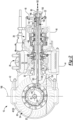
Figure 2 is a section view of the axle assembly along section line 2-2. -
Figure 3 is a section view of a portion of the axle assembly along section line 3-3 with the electric motor module omitted for clarity. -
Figure 4 is an exploded view of examples of a drive pinion extension, shift collar, and support bearing that may be provided with a shift mechanism of the axle assembly. -
Figure 5 is a fragmentary plan view of a portion of the axle assembly illustrating an example of an actuator of the shift mechanism offset from an axis of rotation of a drive pinion. -
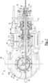
Figure 6 is a section view of a second configuration of an axle assembly along section line 2-2. -
Figure 7 is a section view of a third configuration of an axle assembly along section line 2-2. -
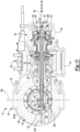
Figure 8 is a section view of a fourth configuration of an axle assembly along section line 2-2. -
Figure 9 is a section view of a portion of the drive pinion that may be provided with the axle assembly ofFigure 8 . -
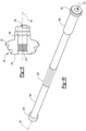
Figure 10 is a side view of a shift collar and linkage shown inFigure 8 . -
Figure 11 is a section view of a fifth configuration of an axle assembly along section line 2-2 - As required, detailed embodiments of the present invention are disclosed herein; however, it is to be understood that the disclosed embodiments are merely exemplary of the invention that may be embodied in various and alternative forms. The figures are not necessarily to scale; some features may be exaggerated or minimized to show details of particular components. Therefore, specific structural and functional details disclosed herein are not to be interpreted as limiting, but merely as a representative basis for teaching one skilled in the art to variously employ the present invention.
- It will also be understood that, although the terms first, second, etc. are, in some instances, used herein to describe various elements, these elements should not be limited by these terms. These terms are only used to distinguish one element from another. For example, a first element could be termed a second element, and similarly a second element could be termed a first element without departing from the scope of the various described embodiments. The first element and the second element are both elements, but they are not the same element.
- The terminology used in the description of the various described embodiments is for the purpose of describing particular embodiments only and is not intended to be limiting. As used in the description of the various described embodiments and the appended claims, the singular forms "a" and "an" and "the" are intended to include the plural forms as well, unless the context clearly indicates otherwise. It will also be understood that the term "and/or" as used herein refers to and encompasses any and all possible combinations of one or more of the associated listed items. It will be further understood that the terms "includes," "including," "comprises," and/or "comprising," when used in this specification, specify the presence of stated features, integers, steps, operations, elements, and/or components, but do not preclude the presence or addition of one or more other features, integers, steps, operations, elements, components, and/or groups thereof.
- Referring to
Figure 1 , an example of anaxle assembly 10 is shown. Theaxle assembly 10 may be provided with a motor vehicle like a truck, farm equipment, military transport or weaponry vehicle, or cargo loading equipment for land, air, or marine vessels. The vehicle may include a trailer for transporting cargo in one or more embodiments. - The
axle assembly 10 is a drive axle assembly. A drive axle assembly is configured to provide torque to one or more wheel assemblies. A wheel assembly may be rotatably supported on theaxle assembly 10. A wheel assembly may include a tire disposed on a wheel. The wheel may be mounted to a wheel hub that may be rotatable about a wheel axis. The wheel hub may be rotatably disposed on theaxle assembly 10. - In some configurations, an
axle assembly 10 includes ahousing assembly 20, adifferential assembly 22, a pair ofaxle shafts 24, anelectric motor 26, atransmission 28, adrive pinion 30, and ashift mechanism 32. The positioning of thedifferential assembly 22, theelectric motor 26, and/or thetransmission 28 may differ from that shown. For instance, thedifferential assembly 22 may be positioned between theelectric motor 26 and thetransmission 28. It is also contemplated that theelectric motor 26 may be remotely positioned from theaxle assembly 10 and may not be part of theaxle assembly 10 in some configurations. For illustration purposes, theaxle assembly 10 will be primarily described in the context of the configuration shown inFigures 1-3 . - Referring to
Figure 1 , thehousing assembly 20 receives various components of theaxle assembly 10. In addition, thehousing assembly 20 may facilitate mounting of theaxle assembly 10 to the vehicle. In some configurations, thehousing assembly 20 includes anaxle housing 40 and adifferential carrier 42. In some configurations, thehousing assembly 20 includes anelectric motor housing 44, atransmission housing 46, anend cover 48, or combinations thereof. - Referring to
Figures 1 and2 , theaxle housing 40 may receive and support theaxle shafts 24. Theaxle housing 40 may include acenter portion 50 and at least onearm portion 52. - The
center portion 50 may be disposed proximate the center of theaxle housing 40. Thecenter portion 50 may help define aninternal cavity 54 that may receive thedifferential assembly 22. - One or
more arm portions 52 may extend from thecenter portion 50. For example, twoarm portions 52 may extend in opposite directions from thecenter portion 50 and away from thedifferential assembly 22. Thearm portions 52 may each have a hollow configuration or tubular configuration that may extend around and may receive acorresponding axle shaft 24 and may help separate or isolate theaxle shaft 24 from the surrounding environment. A wheel hub may be rotatably disposed on anarm portion 52 and may be connected to anaxle shaft 24. - The
differential carrier 42 is configured to be mounted to theaxle housing 40. For instance, thedifferential carrier 42 may be mounted to thecenter portion 50 of theaxle housing 40. Thedifferential assembly 22 may be rotatably supported on thedifferential carrier 42. Thedifferential carrier 42 and theaxle housing 40 may cooperate to define theinternal cavity 54. - The
electric motor housing 44 may extend around or encircle theelectric motor 26. In some configurations, theelectric motor housing 44 extends between thedifferential carrier 42 and thetransmission housing 46. - The
transmission housing 46 may extend around or encircle thetransmission 28. In some configurations, thetransmission housing 46 extends between theelectric motor housing 44 and theend cover 48. - The
end cover 48 may be disposed at an end of thehousing assembly 20. For instance, theend cover 48 may be mounted to an end of thetransmission housing 46 that faces away from thedifferential assembly 22. Theend cover 48 may define apocket 56, which is best shown inFigure 2 . The pocket 58 may be disposed along anaxis 80 about which thedrive pinion 30 is rotatable as will be discussed in more detail below. - Referring to
Figure 2 , thedifferential assembly 22 is disposed in thehousing assembly 20. For instance, thedifferential assembly 22 may be disposed in theinternal cavity 54. Thedifferential assembly 22, which may also be called an axle differential, may transmit torque to theaxle shafts 24 of theaxle assembly 10 and permit theaxle shafts 24 and wheel assemblies to rotate at different velocities in a manner known by those skilled in the art. For example, thedifferential assembly 22 may have aring gear 60 that may be fixedly mounted to a differential case. Thering gear 60 and the differential case are rotatable about adifferential axis 62. The differential case may receive differential gears that may be operatively connected to theaxle shafts 24. - The
axle shafts 24 are configured to transmit torque between thedifferential assembly 22 and a corresponding wheel hub. For example, twoaxle shafts 24 may be provided such that eachaxle shaft 24 extends through adifferent arm portion 52 ofaxle housing 40. Theaxle shafts 24 may be rotatable about a wheel axis. The wheel axis may be the same as thedifferential axis 62 or may differ from thedifferential axis 62. - The
electric motor 26 is configured to provide torque, such as propulsion torque or regenerative braking torque. Propulsion torque may be used to propel the vehicle, such as in a forward or backward direction. Propulsion torque may also be used to hold the vehicle in a stationary position or to help reduce, limit, or prevent vehicle rollback, such as when the vehicle is on an inclined surface. Regenerative braking may provide a regenerative braking torque. Regenerative braking may capture kinetic energy when theelectric motor 26 is used to brake or slow the velocity of the vehicle. Recovered energy may be transmitted from the wheel assemblies to drive theelectric motor 26. Thus, theelectric motor 26 may function as a generator and may be used to charge an electric power source, such as a battery. Theelectric motor 26 may be electrically connected to the electric power source via an inverter in a manner known by those skilled in the art. - The
electric motor 26 includes astator 70 and arotor 72. Thestator 70 may be fixedly positioned with respect to theelectric motor housing 44. Thestator 70 may encircle therotor 72. Therotor 72 is rotatable about anaxis 80 with respect to thestator 70. Therotor 72 may encircle thedrive pinion 30. Theelectric motor 26 may be mounted to or positioned inside of thehousing assembly 20, such as inside theelectric motor housing 44. - The
transmission 28 facilitates the transmission of torque between theelectric motor 26 and thedrive pinion 30. Torque transmission may be bidirectional. Thetransmission 28 may provide gear reduction and multiple gear ratios between therotor 72 and thedrive pinion 30. Thetransmission 28 may be of any suitable type. For instance, thetransmission 28 may be a countershaft transmission, an epicyclic transmission (e.g., a transmission having a planetary gear set), or the like. A countershaft transmission may include a single countershaft or multiple countershafts. Examples of an axle assembly having a single countershaft transmission are disclosed inU.S. Patent Nos. 11,002,352 11,209,072 U.S. Patent Nos. 10,989,288 11,207,976 11,220,176 U.S. Patent Nos. 11,038,396 11,428,297 - An example of a
transmission 28 that is configured as a dual countershaft transmission is shown inFigures 2 and3 . However, it is to be understood that thetransmission 28 is not limited to a countershaft transmission and may be of any suitable type as discussed above. Thetransmission 28 includes one or more sets of gears. For instance, in the configuration shown inFigure 3 , thetransmission 28 may include a set of drive pinion gears 90, a first countershaft gear set 92, and a second countershaft gear set 94. Gears of the first and second countershaft gear sets 92, 94 may be disposed on and rotatable with first andsecond countershafts 96, 96', respectively. The second countershaft gear set 94 may be omitted in a single countershaft configuration. The set of drive pinion gears 90, first countershaft gear set 92, and second countershaft gear set 94, may be replaced with one or more epicyclic or planetary gear sets in other configurations. - In
Figure 3 , set of drive pinion gears 90 may include a plurality of gears, some or all of which may be selectively coupled to thedrive pinion 30. The gears may be independently rotatable with respect to each other. In the configuration shown, the set of drive pinion gears 90 includes a first gear 100, a second gear 102, athird gear 104, and afourth gear 106; however, it is to be understood that a greater or lesser number of gears may be provided. The first gear 100 may mesh with one or more first countershaft gears 110, 110'. The second gear 102 may mesh with one or more second countershaft gears 112, 112'. Thethird gear 104 may mesh with one or more third countershaft gears 114, 114'. Thefourth gear 106 may mesh with one or more fourth countershaft gears 116, 116'. - Referring to
Figure 2 , thedrive pinion 30 operatively connects thetransmission 28 to thedifferential assembly 22. As such, thedrive pinion 30 may transmit torque between thedifferential assembly 22 and thetransmission 28. Thedrive pinion 30 is rotatable about theaxis 80. Thedrive pinion 30 is disposed inside thehousing assembly 20 and may be rotatably supported on thedifferential carrier 42 via one or more roller bearing assemblies. Thedrive pinion 30 has afirst end 120, asecond end 122, agear portion 124, ashaft portion 126, and adrive pinion hole 128. Thedrive pinion 30 may also include adrive pinion extension 130. - The
first end 120 faces toward thedifferential assembly 22. Thefirst end 120 may be part of thegear portion 124. - The
second end 122 is disposed opposite thefirst end 120. As such, thesecond end 122 may face away from thedifferential assembly 22. Thesecond end 122 may be part of theshaft portion 126. - The
gear portion 124 includes a plurality of teeth that mate with corresponding teeth on thering gear 60 of thedifferential assembly 22. Thegear portion 124 may be disposed at or near an end of theshaft portion 126. Thegear portion 124 may be integrally formed with theshaft portion 126 or may be provided as a separate component that may be fixedly disposed on theshaft portion 126. - The
shaft portion 126 extends from thegear portion 124. For instance, theshaft portion 126 may extend from thegear portion 124 to thesecond end 122. Theshaft portion 126 may extend along or about theaxis 80. - The
drive pinion hole 128 is disposed in thedrive pinion 30. Thedrive pinion hole 128 extends along theaxis 80. Thedrive pinion hole 128 extends from thefirst end 120 toward thesecond end 122. In some configurations, thedrive pinion hole 128 is a through hole. For instance, thedrive pinion hole 128 may extend along theaxis 80 from thefirst end 120 of thedrive pinion 30 to thesecond end 122 of thedrive pinion 30. Thedrive pinion hole 128 may have any suitable configuration. For instance, thedrive pinion hole 128 may have a circular cross-section. - Referring to
Figures 2-4 , thedrive pinion extension 130 increases the axial length of thedrive pinion 30. For instance, thedrive pinion extension 130 may be a separate component that is mounted to theshaft portion 126 such that thedrive pinion extension 130 is rotatable about theaxis 80 with theshaft portion 126. For example, thedrive pinion extension 130 may be mounted to theshaft portion 126 with mating splines. Thedrive pinion extension 130 may extend from thesecond end 122 of thedrive pinion 30 in a direction that extends away from thegear portion 124. Thedrive pinion extension 130 may be fixedly positioned with respect to thedrive pinion 30 such that thedrive pinion extension 130 may not move along theaxis 80 with respect to theshaft portion 126. It is also contemplated that thedrive pinion extension 130 may be integrally formed with thedrive pinion 30. For convenience in reference, the term "drive pinion" is used herein to refer to thedrive pinion 30 with or without thedrive pinion extension 130 unless otherwise specified. - Referring primarily to
Figure 4 , thedrive pinion extension 130, if provided, defines a portion of thedrive pinion hole 128. In some configurations, thedrive pinion extension 130 has afirst extension end 140, asecond extension end 142, one ormore slots 144, and aspline 146. Optionally, thedrive pinion extension 130 may include asocket 148. - The
first extension end 140 faces toward theshaft portion 126 of thedrive pinion 30. Thefirst extension end 140 may be omitted if thedrive pinion extension 130 is integrally formed with thedrive pinion 30 as a unitary one-piece component. - The
second extension end 142 is disposed opposite thefirst extension end 140. As such, thesecond extension end 142 faces away from thedifferential assembly 22. The portion of thedrive pinion hole 128 that is disposed in thedrive pinion extension 130 may extend from thefirst extension end 140 toward thesecond extension end 142 or to thesecond extension end 142. Thesecond extension end 142 may be received inside and may be rotatably supported by a support bearing 150 that rotatably supports thedrive pinion extension 130. Thesupport bearing 150 may be received in thepocket 56 of theend cover 48 as shown inFigure 2 . - Referring to
Figures 2 and4 , one ormore slots 144 may be provided with thedrive pinion extension 130. Aslot 144 may extend or be elongated in an axial direction with respect to theaxis 80 or in a direction that extends along or parallel to theaxis 80. Aslot 144 may be a closed end slot that extends between a first slot end and a second slot end. Theslot 144 may extend from thedrive pinion hole 128 away from theaxis 80. For instance, theslot 144 may extend from thedrive pinion hole 128 through thedrive pinion extension 130 to an exterior surface of thedrive pinion extension 130 that faces away from theaxis 80. Oneslot 144 is visible inFigure 4 . Twoslots 144 are visible inFigure 2 . Theseslots 144 are aligned with each other and disposed on opposite sides of theaxis 80. - Referring primarily to
Figure 4 , thespline 146 facilitates mounting and axial movement of a shift collar as will be discussed in more detail below. Thespline 146 may include a plurality of teeth that extend from an exterior side of thedrive pinion extension 130 in a direction that extends away from theaxis 80 and thedrive pinion hole 128. Thespline 146 may be axially positioned between thefirst extension end 140 and thesecond extension end 142. For instance, thespline 146 may be axially positioned between thefirst extension end 140 and theslot 144. - The
socket 148, if provided, receives thedrive pinion 30. Thesocket 148 may extend from thefirst extension end 140. Thefirst end 120 of thedrive pinion 30 may be disposed inside thesocket 148 when thedrive pinion extension 130 is provided as a separate part. Thedrive pinion 30 may be fastened to thesocket 148 in any suitable manner, such as with a fastener, threaded connection, mating splines, or the like. It is also contemplated that asocket 148 may be provided with thedrive pinion 30 and that thedrive pinion extension 130 may be received inside the socket. - Referring to
Figure 2 , theshift mechanism 32 facilitates coupling of thedrive pinion 30 to thetransmission 28. For instance, theshift mechanism 32 is configured to selectively connect a gear of thetransmission 28, such as a member of the set of drive pinion gears 90, to thedrive pinion 30. Theshift mechanism 32 may couple one gear at a time to thedrive pinion 30. In some configurations, a gear that is coupled to thedrive pinion 30 may be rotatable about theaxis 80 with thedrive pinion 30. Theshift mechanism 32 may have any suitable configuration. In some configurations, theshift mechanism 32 includes ashift collar 160, alinkage 162, and anactuator 164. Theshift mechanism 32 may also include afastener 166. - The
shift collar 160, which is best shown inFigure 4 , is rotatable about theaxis 80 with thedrive pinion 30. In addition, theshift collar 160 is moveable along theaxis 80 with respect to thedrive pinion 30. Theshift collar 160 may selectively connect a gear of thetransmission 28 to thedrive pinion 30. For instance, theshift collar 160 may selectively connect a member of the set of drive pinion gears 90 to thedrive pinion 30 as will be discussed in more detail below. In at least one configuration, theshift collar 160 may include afirst end 170, asecond end 172, ashift collar hole 174, ashift collar spline 176, and ashift collar gear 178. - The
first end 170 may face toward thedrive pinion 30. Thefirst end 170 may encircle theaxis 80. - The
second end 172 is disposed opposite thefirst end 170. As such, thesecond end 172 may face away from thedrive pinion 30. - The
shift collar hole 174 extends along theaxis 80 between thefirst end 170 to thesecond end 172. Theshift collar hole 174 may be configured as a through hole that may extend from thefirst end 170 to thesecond end 172. Thedrive pinion 30 or thedrive pinion extension 130 may be received inside theshift collar hole 174. - The
shift collar spline 176 is configured to couple theshift collar 160 to thedrive pinion 30, such as to thedrive pinion extension 130 of thedrive pinion 30. Theshift collar spline 176 may be disposed in theshift collar hole 174. Theshift collar spline 176 may include teeth that extend toward theaxis 80. Theshift collar spline 176 may mate with thespline 146. The mating splines may allow theshift collar 160 to move in an axial direction or along theaxis 80 while limiting or inhibiting rotation of theshift collar 160 about theaxis 80 with respect to thedrive pinion 30. Thus, theshift collar 160 may be rotatable about theaxis 80 with thedrive pinion 30 when theshift collar spline 176 mates with thespline 146. - The
shift collar gear 178 is engageable with a gear of thetransmission 28. Theshift collar gear 178 may be disposed between thefirst end 170 and thesecond end 172 of theshift collar 160. Theshift collar gear 178 may be disposed opposite theshift collar hole 174. Theshift collar gear 178 may have teeth that may be arranged around theaxis 80 and that may extend away from theaxis 80 and theshift collar hole 174. - Referring to
Figure 2 , thelinkage 162 operatively connects theshift collar 160 and theactuator 164. Thelinkage 162 is received in thedrive pinion hole 128. As such, thelinkage 162 may be received inside thedrive pinion 30 and thedrive pinion extension 130 if adrive pinion extension 130 is provided. Thedrive pinion 30, thedrive pinion extension 130, or both may encircle thelinkage 162. Thelinkage 162 may extend along theaxis 80. Thelinkage 162 is coupled to theshift collar 160. As such, thelinkage 162 may be rotatable about theaxis 80 with theshift collar 160. Thelinkage 162 may be disposed inside theshift collar 160. Thelinkage 162 may be fixedly coupled to theshift collar 160. Thelinkage 162 may have any suitable configuration. For instance, thelinkage 162 may be configured as a shaft, rod, or the like. - The
actuator 164 is configured to move theshift collar 160 along theaxis 80. For instance, theactuator 164 is configured to move thelinkage 162 and theshift collar 160 along theaxis 80 to selectively connect or selectively couple a gear of thetransmission 28 to thedrive pinion 30 or to decouple theshift collar 160 from a gear of thetransmission 28. Theactuator 164 is coupled to thelinkage 162. - The
actuator 164 may be provided in various locations. In some configurations, theactuator 164 is disposed in or received in theinternal cavity 54 of thehousing assembly 20. For instance, theactuator 164 may be disposed in theaxle housing 40, in thedifferential carrier 42, or both. In the configuration shown inFigure 2 , theactuator 164 is disposed in theinternal cavity 54 and in thedifferential carrier 42. Theactuator 164 may be axially positioned with respect to theaxis 80 between thefirst end 120 of thedrive pinion 30 and thedifferential axis 62. For instance, theactuator 164 may be axially positioned along or with respect to theaxis 80 between thefirst end 120 and adifferential axis plane 168 that may be disposed substantially perpendicular to theaxis 80. The term "substantially perpendicular" is used herein to designate features or axes that are the same as or very close to perpendicular and includes features that are within ±3° of being perpendicular each other. In such a configuration, theactuator 164 may be mounted to thedifferential carrier 42. - In the configuration shown in
Figure 6 , theactuator 164 is disposed further from thefirst end 120 of thedrive pinion 30 than in the configuration shown inFigure 2 . For instance, theactuator 164 may be positioned further from thedrive pinion 30 than thedifferential axis 62 is positioned from thedrive pinion 30. For instance, theactuator 164 may be axially positioned along or with respect to theaxis 80 between thedifferential axis plane 168 and the end or bowl cover of the axle housing 40 (e.g., the left end from the perspective shown inFigure 2 ). In such a configuration, theactuator 164 may be disposed in theaxle housing 40 and may be mounted to theaxle housing 40. - In the configuration shown in
Figure 7 , theactuator 164 is not disposed in or received in theinternal cavity 54 of thehousing assembly 20. Instead, theactuator 164 or a portion thereof may be disposed outside of theinternal cavity 54. InFigure 7 , theactuator 164 is mounted to theaxle housing 40 and is disposed outside of theaxle housing 40. In such a configuration, thelinkage 162 may extend through a hole in the end or bowl cover of theaxle housing 40 to facilitate coupling to theactuator 164. - Referring primarily to
Figure 2 , thefastener 166 couples thelinkage 162 to theshift collar 160. Thefastener 166 may be of any suitable type, such as a pin, dowel, threaded fastener, or the like. Thefastener 166 may be fixedly coupled to theshift collar 160, thelinkage 162, or both. For instance, thefastener 166 may protrude from thelinkage 162 into one or more fastener holes 180, which are best shown inFigure 4 , in theshift collar 160. Thefastener 166 may be received in the slot orslots 144 of thedrive pinion 30 or drivepinion extension 130. As such, thefastener 166 may be moveable within the slot orslots 144 in an axial direction. In some configurations, thefastener 166 is receivable in thepocket 56 of theend cover 48, such as when theshift collar 160 is actuated away from thedrive pinion 30. - The
shift collar 160, thelinkage 162, and thefastener 166 may be moveable together along theaxis 80. The length of theslot 144 may limit the distance that theshift collar 160, thelinkage 162, and thefastener 166 may move along theaxis 80. For instance, axial movement of theshift collar 160, thelinkage 162, and thefastener 166 may be inhibited when thefastener 166 engages or contacts a closed end of theslot 144. - The
shift collar 160, thelinkage 162, and thefastener 166 may be moveable along theaxis 80 in afirst direction 190 and in asecond direction 192 that is disposed opposite thefirst direction 190. Theshift collar 160, thelinkage 162, and thefastener 166 may move along theaxis 80 in thefirst direction 190 when theactuator 164 moves theshift collar 160 toward theactuator 164, or to the left from the perspective shown inFigures 2 ,6 , and7 . Theshift collar 160, thelinkage 162, and thefastener 166 may move along theaxis 80 and thesecond direction 192 when theactuator 164 moves theshift collar 160 away from theactuator 164, or to the right from the perspective shown inFigures 2 ,6 , and7 . - In the configurations shown in
Figures 2 ,6 , and7 , theactuator 164 may or may not be disposed along or intersect theaxis 80. Anactuator 164 that is disposed along theaxis 80 or that may intersect theaxis 80 may be directly coupled to thelinkage 162. As some nonlimiting examples, theactuator 164 may be a linear actuator or solenoid that may exert force on thelinkage 162 to move thelinkage 162 along theaxis 80. Referring toFigure 5 , an example of a fragmentary plan view is shown that illustrates theactuator 164 being offset from and not intersected by theaxis 80. In such a configuration, theactuator 164 may be coupled to thelinkage 162 with a secondary linkage 200 that may connect the actuator to thelinkage 162. The secondary linkage 200 may have any suitable configuration, such as a shaft, cable such as a push-pull cable, or the like. - The
actuator 164 may move the secondary linkage 200, thelinkage 162, and theshift collar 160 along theaxis 80, which is represented in phantom inFigure 5 . Movement along theaxis 80 to the left or in thefirst direction 190 from the position shown inFigures 2 and4 may move theshift collar gear 178 out of engagement with thefourth gear 106 to a first neutral position that is disposed between thefourth gear 106 and thethird gear 104. Further actuation in thefirst direction 190 may move theshift collar gear 178 into engagement with thethird gear 104, followed by a second neutral position between thethird gear 104 and the second gear 102, and into engagement with the second gear 102. - Referring to
Figure 8 , another configuration of an axle assembly is shown. This configuration includeshousing assembly 20, adifferential assembly 22, a pair ofaxle shafts 24, anelectric motor 26, and atransmission 28 as previously described. The axle assembly also includes adrive pinion 30' and a shift mechanism 32'. - The
drive pinion 30' is the same as thedrive pinion 30 previously described, but may have a shorter axial length. In addition, thedrive pinion 30' has a mating feature 210', which is best shown inFigure 9 , noting thatFigure 9 only shows a portion of thedrive pinion 30'. - Referring primarily to
Figures 9 and 10 , the mating feature 210' is configured to rotatably couple thedrive pinion 30' to a linkage 162' of the shift mechanism 32' such that thedrive pinion 30' and linkage 162' are rotatable together about theaxis 80. The mating feature 210' permits the linkage 162' to move along theaxis 80 with respect to thedrive pinion 30'. The mating feature 210' may be disposed in thedrive pinion hole 128. The mating feature 210' may have any suitable configuration. For instance, the mating feature 210' may be configured with a male configuration, female configuration, or combinations thereof. As some examples, the mating feature 210' may be a pin, a key, one or more teeth, or the like. InFigure 9 , the mating feature 210' is depicted as one or more teeth, such as a spline or spline teeth that extend toward theaxis 80. The mating feature 210' may be located inside thegear portion 124, theshaft portion 126, or both. In the configuration shown, the mating feature 210' is located inside thegear portion 124 of thedrive pinion 30'. - Referring to
Figure 8 , the shift mechanism 32' facilitates coupling of thedrive pinion 30' to thetransmission 28 and is configured to selectively connect a gear of thetransmission 28, such as a member of the set of drive pinion gears 90, to thedrive pinion 30' as previously discussed with respect to shiftmechanism 32. Theshift mechanism 32 includes anactuator 164 as previously discussed as well as a shift collar 160', a linkage 162', and asupport shaft 220'. - Referring to
Figures 8 and10 , the shift collar 160' is rotatable about theaxis 80 with thedrive pinion 30' and is moveable along theaxis 80 with respect to thedrive pinion 30'. The shift collar 160' may selectively connect a gear of thetransmission 28, such as a member of the set of drive pinion gears 90, to thedrive pinion 30' as previously discussed. In at least one configuration, the shift collar 160' is fixedly coupled to or integrally formed with the linkage 162' and includes a shift collar hole 174' as well as ashift collar gear 178 as previously described. - The shift collar hole 174' extends along the
axis 80 may be configured as a through hole. Thesupport shaft 220' may be received inside the shift collar hole 174'. - The linkage 162' extends from the shift collar 160' and operatively connects the shift collar 160' to the
drive pinion 30' and theactuator 164. The linkage 162' is rotatable about theaxis 80 with the shift collar 160'. Thelinkage 162 is received in thedrive pinion hole 128 and may protrude out of thedrive pinion 30' from thefirst end 120 and from thesecond end 122 of thedrive pinion 30'. As such, the linkage 162' may have a greater axial length than thedrive pinion 30'. In some configurations, the linkage 162' is configured as a hollow tube that extends along theaxis 80. The linkage 162' may encircle theaxis 80 and thesupport shaft 220'. In some configurations, the linkage 162' includes a linkage mating feature 222' and a shift block 224'. - The linkage mating feature 222' is configured to rotatably couple the linkage 162' to the
drive pinion 30' and permit the linkage 162' to move along theaxis 80 with respect to thedrive pinion 30'. The linkage mating feature 222' may be disposed in thedrive pinion hole 128. The linkage mating feature 222' engages the mating feature 210' of thedrive pinion 30' and may have any suitable configuration that is compatible with the mating feature 210'. For instance, the linkage mating feature 222' may be configured with a male configuration, female configuration, or combinations thereof. As some examples, the linkage mating feature 222' may be a recess, pin, key, one or more teeth, or the like. In the configuration shown inFigure 10 , the linkage mating feature 222' is depicted as one or more teeth, such as a spline or spline teeth that extend away theaxis 80 and that are received between corresponding teeth of the mating feature 210' of thedrive pinion 30' throughout the axial travel distance of the linkage 162'. The linkage mating feature 222' may have a greater axial length than the mating feature 210' of thedrive pinion 30'. The linkage mating feature 222' may be located inside thegear portion 124, theshaft portion 126, or both. In the configuration shown, at least a portion of the linkage mating feature 222' is located inside thegear portion 124 of thedrive pinion 30'. - The shift block 224' operatively connects the linkage 162' to the
actuator 164. Depending on the size of thedrive pinion hole 128, the shift block 224' may be integrally formed with the linkage 162' or may be a separate component that is fastened to the linkage 162'. For instance, the shift block 224' may be a separate component that is fixedly attached to the linkage 162' after the linkage 162' is inserted through thedrive pinion hole 128. The shift block 224' is disposed at or near an end of the linkage 162' that is disposed opposite the shift collar 160'. As such, the shift block 224' may be disposed inside theaxle housing 40, thedifferential carrier 42, or both. The shift block 224' may have any suitable configuration that is compatible with theactuator 164 and the linkage 162'. InFigures 8 and11 , a simplified depiction of theactuator 164 is shown in which the shift block 224' is moveable along or parallel to theaxis 80. - The
support shaft 220' supports the shift collar 160' and the linkage 162'. Thesupport shaft 220' extends along theaxis 80 and may be encircled by the shift collar 160', the linkage 162', or both. Thesupport shaft 220' may extend through the shift collar 160' and the linkage 162'. For instance, thesupport shaft 220' may protrude from an end of the shift collar 160' and protrude from an end of the linkage 162'. The ends of thesupport shaft 220' may be supported by thehousing assembly 20. - In some configurations, such as the configuration shown in
Figure 8 , thesupport shaft 220' is rotatable about theaxis 80. In such a configuration, thesupport shaft 220' is rotatably supported on bearings 230', such as a roller bearing assembly. In the configuration shown, one bearing 230' is disposed on theaxle housing 40 and another bearing 230' is disposed on thetransmission housing 46. Thesupport shaft 220' may not translate along theaxis 80. - In some configurations, the
support shaft 220' may be rotatable about theaxis 80 with the shift collar 160' and the linkage 162'. In some configurations, thesupport shaft 220' may contact or engage the shift collar 160' and/or the linkage 162' but the shift collar 160' and the linkage 162' may be free to slide or translate along theaxis 80 with respect to thesupport shaft 220'. For instance, thesupport shaft 220' may be connected to the shift collar 160' and/or the linkage 162' with one or more mating features, such as a key, pin, teeth, mating splines, or the like. - In some configurations, the
support shaft 220' is not rotatable about theaxis 80. An example of such a configuration is shown inFigure 11 . In this configuration, the bearings 230' may be omitted and thesupport shaft 220' is stationary. The shift collar 160' and the linkage 162' are rotatable about theaxis 80 with respect to thesupport shaft 220' and moveable along theaxis 80 with respect to thesupport shaft 220'. In some configurations, the shift collar 160' and linkage 162' may be spaced apart from thesupport shaft 220' such that a gap is provided therebetween. - One or more bearings 240' may be provided between the
support shaft 220' and the shift collar 160' and/or the linkage 162' to facilitate rotation of the shift collar 160' and the linkage 162' with respect to thesupport shaft 220' and translation of the shift collar 160' and the linkage 162' along theaxis 80 with respect to thesupport shaft 220'. For instance, a bearing 240' may include a plurality of bearing elements such as ball bearings. InFigure 11 , a single bearing 240' is shown but it is to be understood that additional bearings 240' may be provided. It is contemplated that the bearing 240' may move axially with the shift collar 160' and the linkage 162' or that the shift collar 160' and the linkage 162' may move axially with respect to the bearing 240'. - One or more bearings 242' may be provided between the
support shaft 220' and the shift block 224' to facilitate rotation of the shift collar 160' and the linkage 162' with respect to the shift block 224' and translation of the shift collar 160' and the linkage 162' along theaxis 80 with respect to the shift block 224'. In some configurations, the shift block 224' may encircle the bearing 242' and the bearing 242' may encircle the linkage 162' and may move axially with the linkage 162' and the shift block 224'. For instance, the linkage 162', shift block 224', and bearing 242' may be moveable along theaxis 80 to the left from the position shown to move the shift collar 160' to a neutral position or to engage a different member of the set of drive pinion gears. - It is contemplated that in
Figures 8 and11 , theactuator 164 may be disposed closer to thedrive pinion 30' than is shown, such as closer to thedifferential axis plane 168, or between thedifferential axis plane 168 and thedrive pinion 30' similar to the positioning shown inFigure 2 . It is also contemplated that theactuator 164 could also be disposed outside of thehousing assembly 20 like the configuration shown inFigure 7 . In such a configuration, thesupport shaft 220' could be rotatable as inFigure 8 or non-rotatable as inFigure 11 and the actuator shaft or another linkage may extend from the externally mountedactuator 164 into theinternal cavity 54 of thehousing assembly 20 to connect theactuator 164 to the linkage 162'. - The present invention may help reduce the standout or axial length of an axle assembly. For instance, the present invention may allow a shift mechanism to be placed closer to the axle housing as compared to configurations in which the shift mechanism is positioned at the end of the axle assembly adjacent to the transmission. Positioning the shift mechanism at or near the end of the axle assembly adjacent to the transmission increases the standout or axial length of the axle assembly, increases the space required to accommodate the axle assembly when mounted on the vehicle. For instance, the present invention may reduce the axial length by approximately 60 mm in one or more configurations. In addition, positioning the shift mechanism at or near the end of the axle assembly requires that the housing assembly extend further away from the axis (e.g., in a radial direction) to provide adequate space to accommodate and package the shift mechanism. The present invention employs a hollow drive pinion that allows the shift mechanism to be moved closer to the opposite end of the axle assembly, which in turn allows an end cover to be provided that may be located both closer to the axis and that extends a shorter length along the axis.
- While exemplary embodiments are described above, it is not intended that these embodiments describe all possible forms of the invention. Rather, the words used in the specification are words of description rather than limitation, and it is understood that various changes may be made without departing from the spirit and scope of the invention. Additionally, the features of various implementing embodiments may be combined to form further embodiments of the invention.
Claims (15)
- An axle assembly comprising:a drive pinion that is rotatable about an axis and that has a drive pinion hole that extends along the axis from a first end of the drive pinion toward a second end of the drive pinion that is disposed opposite the first end;a transmission that comprises a set of gears; anda shift mechanism that comprises:a shift collar that is rotatable about the axis with the drive pinion and moveable along the axis with respect to the drive pinion;a linkage that is coupled to the shift collar, wherein the linkage is received in the drive pinion hole of the drive pinion; andan actuator that is coupled to the linkage and is configured to move the linkage and the shift collar along the axis to selectively connect a member of the set of gears to the drive pinion.
- The axle assembly of claim 1 wherein the linkage extends along the axis.
- The axle assembly of any preceding claim wherein the linkage is rotatable about the axis with the shift collar.
- The axle assembly of any preceding claim wherein the linkage is disposed inside the shift collar.
- The axle assembly of any preceding claim wherein the linkage is fixedly coupled to the shift collar.
- The axle assembly of any preceding claim wherein the drive pinion includes a drive pinion extension that is rotatable about the axis, wherein the shift collar is disposed on the drive pinion extension and the linkage is received inside the drive pinion extension.
- The axle assembly of claim 6 wherein the drive pinion extension has a slot that extends in an axial direction with respect to the axis, and a fastener is received in the slot and couples the linkage to the shift collar, preferably the fastener is coupled to the linkage and the shift collar, and the fastener is moveable in the slot in the axial direction and/or the axle assembly includes an end cover that is disposed at an end of the axle assembly, and/or the end cover defines a pocket inside which a support bearing is received that rotatably supports the drive pinion, and/or the fastener is receivable in the pocket.
- The axle assembly of claim 7 wherein the linkage, the fastener, and the shift collar are moveable along the axis in a first direction when the actuator moves the shift collar toward the actuator, preferably the linkage, the fastener, and the shift collar are moveable along the axis in a second direction that is disposed opposite the first direction when the actuator moves the shift collar away from the actuator.
- The axle assembly of any preceding claim wherein the axle assembly has an electric motor that includes a rotor that is rotatable about the axis, the rotor encircles the drive pinion, and the drive pinion encircles the linkage.
- The axle assembly of any preceding claim wherein the actuator is disposed along the axis.
- The axle assembly of any preceding claim wherein the axle assembly includes an axle housing and a differential carrier that cooperate to define an internal cavity inside which a differential assembly and the actuator are received, preferably the actuator is mounted to the differential carrier and/or the differential assembly is rotatable about a differential axis and the actuator is axially positioned with respect to the axis between the first end of the drive pinion and the differential axis, and/or the actuator is mounted to the axle housing.
- The axle assembly of any one of claims 1-11 wherein the axle assembly includes an axle housing and a differential carrier that cooperate to define an internal cavity inside which a differential assembly and the actuator are received, the differential assembly is rotatable about a differential axis, and the actuator is positioned further from the drive pinion than the differential axis is positioned from the drive pinion, preferably the actuator is mounted to the axle housing..
- The axle assembly of any one of claims 1-10 wherein the axle assembly includes an axle housing and a differential carrier that cooperate to define an internal cavity inside which a differential assembly is received, wherein the actuator is disposed outside of the internal cavity, preferably the actuator is mounted to the axle housing.
- The axle assembly of any one of claims 1-6 and 9-13 when dependent on any one of claims 1-6 wherein the drive pinion is rotatably coupled to the linkage such that the linkage is rotatable about the axis with the drive pinion and moveable along the axis with respect to the drive pinion, the drive pinion is rotatably coupled to the linkage in the drive pinion hole and/or the drive pinion and the linkage are rotatably coupled with mating splines.
- The axle assembly of any one of claims 1-6 and 9-14 when dependent on any one of claims 1-6 further comprising a support shaft that extends along the axis and that is encircled by the linkage and the shift collar, preferably the support shaft is rotatable about the axis and/or the linkage is rotatable about the axis with the support shaft, or the support shaft is not rotatable about the axis and the linkage is rotatable about the axis with respect to the support shaft.
Applications Claiming Priority (1)
| Application Number | Priority Date | Filing Date | Title |
|---|---|---|---|
| US18/479,183 US12043099B1 (en) | 2023-10-02 | 2023-10-02 | Axle assembly having a shift mechanism |
Publications (1)
| Publication Number | Publication Date |
|---|---|
| EP4534874A1 true EP4534874A1 (en) | 2025-04-09 |
Family
ID=91953521
Family Applications (1)
| Application Number | Title | Priority Date | Filing Date |
|---|---|---|---|
| EP24203562.4A Pending EP4534874A1 (en) | 2023-10-02 | 2024-09-30 | Axle assembly having a shift mechanism |
Country Status (3)
| Country | Link |
|---|---|
| US (1) | US12043099B1 (en) |
| EP (1) | EP4534874A1 (en) |
| CN (1) | CN119755321B (en) |
Families Citing this family (2)
| Publication number | Priority date | Publication date | Assignee | Title |
|---|---|---|---|---|
| CN117083190A (en) * | 2021-03-10 | 2023-11-17 | 奥美尼传动系统技术有限责任公司 | Electric drive system |
| JP7753279B2 (en) * | 2023-03-22 | 2025-10-14 | 株式会社Ijtt | Electric axle device for vehicles |
Citations (10)
| Publication number | Priority date | Publication date | Assignee | Title |
|---|---|---|---|---|
| CA2030950C (en) * | 1990-05-17 | 1994-03-22 | Mahlon Lloyd Love | Modular drive axle having a three-speed transmission |
| EP2783964A1 (en) * | 2013-03-29 | 2014-10-01 | Honda Motor Co., Ltd. | Transmission |
| US10989288B1 (en) | 2019-10-07 | 2021-04-27 | Arvinmeritor Technology, Llc | Axle assembly having a multi-speed countershaft transmission |
| US11002352B2 (en) | 2019-10-07 | 2021-05-11 | Arvinmeritor Technology, Llc | Axle assembly having an axle housing |
| US11038396B2 (en) | 2018-11-30 | 2021-06-15 | Arvinmeritor Technology, Llc | Axle assembly having an electric motor module and method of assembly |
| US11209072B2 (en) | 2019-10-07 | 2021-12-28 | Arvinmeritor Technology, Llc | Axle assembly having a multi-speed transmission |
| US11207976B2 (en) | 2019-10-07 | 2021-12-28 | Arvinmeritor Technology, Llc | Axle assembly having a multi-speed countershaft transmission |
| US11220176B1 (en) | 2021-02-18 | 2022-01-11 | Arvinmeritor Technology, Llc | Axle assembly having a gear reduction module with countershaft gear sets |
| US11428297B1 (en) | 2021-05-05 | 2022-08-30 | Arvinmeritor Technology, Llc | Axle assembly having a gear reduction module with multiple gear sets |
| US11441657B2 (en) | 2021-02-18 | 2022-09-13 | Arvinmeritor Technology, Llc | Axle assembly and shift mechanism for a shift collar |
Family Cites Families (28)
| Publication number | Priority date | Publication date | Assignee | Title |
|---|---|---|---|---|
| US1981236A (en) | 1932-12-22 | 1934-11-20 | Charles H Logue | Variable speed power transmitting mechanism |
| US5531653A (en) * | 1995-01-13 | 1996-07-02 | Dana Corporation | Selectively lockable differential assembly |
| US6176146B1 (en) | 1998-11-12 | 2001-01-23 | Zf Meritor, Llc | Output shaft arrangement for manual transmission auxiliary boxes |
| DE102005020606A1 (en) | 2005-05-03 | 2006-12-14 | Daimlerchrysler Ag | Gearbox with countershaft which can be decoupled in a direct gear |
| JP4572956B2 (en) | 2008-06-03 | 2010-11-04 | トヨタ自動車株式会社 | Vehicle drive device |
| JP6278332B2 (en) | 2013-04-22 | 2018-02-14 | スズキ株式会社 | Transmission control device |
| DE102013108416B4 (en) * | 2013-08-05 | 2016-03-24 | Gkn Driveline International Gmbh | Electric drive and method for controlling such an electric drive |
| WO2016177392A1 (en) | 2015-05-04 | 2016-11-10 | Volvo Truck Corporation | Method for disengaging an inactive gear of a dual clutch transmission and a corresponding transmission |
| US9719563B2 (en) | 2015-05-22 | 2017-08-01 | Arvinmeritor Technology, Llc | Axle assembly having a tapered spline arrangement |
| KR101755833B1 (en) | 2015-09-02 | 2017-07-10 | 현대자동차주식회사 | Transmission for vehicle |
| US20180015816A1 (en) | 2016-07-12 | 2018-01-18 | GM Global Technology Operations LLC | Parallel-shaft transmission assembly with selectable electrification |
| US10500941B2 (en) | 2017-08-18 | 2019-12-10 | Arvinmeritor Technology, Llc | Axle assembly having an electric motor module and a shift mechanism |
| US10500940B2 (en) * | 2017-08-18 | 2019-12-10 | Arvinmeritor Technology, Llc | Axle assembly having an electric motor module and a gear reduction module |
| US11273700B2 (en) * | 2017-08-18 | 2022-03-15 | Arvinmeritor Technology, Llc | Axle assembly having an electric motor module |
| US10591037B2 (en) * | 2018-08-09 | 2020-03-17 | Arvinmeritor Technology, Llc | Drive axle system having a planetary interaxle differential unit |
| US10935120B2 (en) | 2018-11-30 | 2021-03-02 | Arvinmeritor Technology, Llc | Axle assembly having a spigot bearing assembly |
| US10985635B2 (en) | 2018-11-30 | 2021-04-20 | Arvinmeritor Technology, Llc | Axle assembly having a resolver and a method of assembly |
| US10808830B2 (en) | 2018-11-30 | 2020-10-20 | Arvinmeritor Technology, Llc | Axle assembly with multiple lubricant chambers |
| US10808834B2 (en) | 2018-11-30 | 2020-10-20 | Arvinmeritor Technology, Llc | Axle assembly and method of control |
| US10704597B2 (en) | 2018-11-30 | 2020-07-07 | Arvinmeritor Technology, Llc | Axle assembly having a bearing preload module |
| US10801602B2 (en) | 2018-11-30 | 2020-10-13 | Arvinmeritor Technology, Llc | Axle assembly having counterphase planet gears |
| US11441644B2 (en) | 2019-10-07 | 2022-09-13 | Arvinmeritor Technology, Llc | Axle assembly having a multi-speed transmission and a drop gear set |
| US10975942B1 (en) * | 2019-10-10 | 2021-04-13 | Arvinmeritor Technology, Llc | Axle assembly having a differential assembly |
| US11333236B2 (en) * | 2019-11-22 | 2022-05-17 | Arvinmeritor Technology, Llc | Drivetrain system having an axle assembly |
| US11614148B2 (en) * | 2021-02-18 | 2023-03-28 | Arvinmeritor Technology, Llc | Axle assembly having a shift collar |
| US11168783B1 (en) | 2021-02-18 | 2021-11-09 | Arvinmeritor Technology, Llc | Axle assembly having a transmission module |
| US11566705B2 (en) | 2021-04-01 | 2023-01-31 | Arvinmeritor Technology, Llc | Axle assembly and shift mechanism for a shift collar |
| DE102021208061A1 (en) * | 2021-07-27 | 2023-02-02 | Zf Friedrichshafen Ag | electric vehicle transmission |
-
2023
- 2023-10-02 US US18/479,183 patent/US12043099B1/en active Active
-
2024
- 2024-09-30 EP EP24203562.4A patent/EP4534874A1/en active Pending
- 2024-09-30 CN CN202411385301.0A patent/CN119755321B/en active Active
Patent Citations (10)
| Publication number | Priority date | Publication date | Assignee | Title |
|---|---|---|---|---|
| CA2030950C (en) * | 1990-05-17 | 1994-03-22 | Mahlon Lloyd Love | Modular drive axle having a three-speed transmission |
| EP2783964A1 (en) * | 2013-03-29 | 2014-10-01 | Honda Motor Co., Ltd. | Transmission |
| US11038396B2 (en) | 2018-11-30 | 2021-06-15 | Arvinmeritor Technology, Llc | Axle assembly having an electric motor module and method of assembly |
| US10989288B1 (en) | 2019-10-07 | 2021-04-27 | Arvinmeritor Technology, Llc | Axle assembly having a multi-speed countershaft transmission |
| US11002352B2 (en) | 2019-10-07 | 2021-05-11 | Arvinmeritor Technology, Llc | Axle assembly having an axle housing |
| US11209072B2 (en) | 2019-10-07 | 2021-12-28 | Arvinmeritor Technology, Llc | Axle assembly having a multi-speed transmission |
| US11207976B2 (en) | 2019-10-07 | 2021-12-28 | Arvinmeritor Technology, Llc | Axle assembly having a multi-speed countershaft transmission |
| US11220176B1 (en) | 2021-02-18 | 2022-01-11 | Arvinmeritor Technology, Llc | Axle assembly having a gear reduction module with countershaft gear sets |
| US11441657B2 (en) | 2021-02-18 | 2022-09-13 | Arvinmeritor Technology, Llc | Axle assembly and shift mechanism for a shift collar |
| US11428297B1 (en) | 2021-05-05 | 2022-08-30 | Arvinmeritor Technology, Llc | Axle assembly having a gear reduction module with multiple gear sets |
Also Published As
| Publication number | Publication date |
|---|---|
| US12043099B1 (en) | 2024-07-23 |
| CN119755321A (en) | 2025-04-04 |
| CN119755321B (en) | 2025-06-24 |
Similar Documents
| Publication | Publication Date | Title |
|---|---|---|
| EP3805012B1 (en) | Axle assembly having axle housing | |
| CN119755321B (en) | Axle assembly with gear shifting mechanism | |
| EP4043746B1 (en) | Axle assembly having a rotor bearing assembly | |
| CN117922264A (en) | Drive axle system with multiple motors | |
| US10591037B2 (en) | Drive axle system having a planetary interaxle differential unit | |
| US9353852B2 (en) | Actuator coupling mechanism | |
| US20240116358A1 (en) | Disconnect differential | |
| EP4067703A1 (en) | Axle assembly and shift mechanism for a shift collar | |
| EP3401563B1 (en) | Clearance control swash plate device and single-shaft two-speed drive system with friction clutch applied thereto | |
| CN114962577B (en) | Axle assembly with barrel cam | |
| US11828355B1 (en) | Disconnector apparatus | |
| CN112829580B (en) | Drive train system with axle assembly | |
| US9033842B2 (en) | Transfer case with stationary low range planetary | |
| EP4455517A2 (en) | Axle assembly having a shift collar | |
| US20250136068A1 (en) | Axle assembly having a drive pinion brake | |
| EP4338994A1 (en) | Axle assembly having a planetary gear set | |
| EP4257850A1 (en) | Axle assembly having a differential brake | |
| EP1063118B1 (en) | Power train system for a vehicle | |
| JP5844655B2 (en) | Power transmission device and transfer device | |
| US4128022A (en) | Rotatable shaft coupling | |
| KR102648797B1 (en) | Disconnector apparatus | |
| EP4446621A2 (en) | Axle assembly having a shift mechanism |
Legal Events
| Date | Code | Title | Description |
|---|---|---|---|
| PUAI | Public reference made under article 153(3) epc to a published international application that has entered the european phase |
Free format text: ORIGINAL CODE: 0009012 |
|
| STAA | Information on the status of an ep patent application or granted ep patent |
Free format text: STATUS: THE APPLICATION HAS BEEN PUBLISHED |
|
| AK | Designated contracting states |
Kind code of ref document: A1 Designated state(s): AL AT BE BG CH CY CZ DE DK EE ES FI FR GB GR HR HU IE IS IT LI LT LU LV MC ME MK MT NL NO PL PT RO RS SE SI SK SM TR |
|
| STAA | Information on the status of an ep patent application or granted ep patent |
Free format text: STATUS: REQUEST FOR EXAMINATION WAS MADE |
|
| 17P | Request for examination filed |
Effective date: 20250827 |