EP4534840A1 - Reciprocating compressor - Google Patents
Reciprocating compressor Download PDFInfo
- Publication number
- EP4534840A1 EP4534840A1 EP24201231.8A EP24201231A EP4534840A1 EP 4534840 A1 EP4534840 A1 EP 4534840A1 EP 24201231 A EP24201231 A EP 24201231A EP 4534840 A1 EP4534840 A1 EP 4534840A1
- Authority
- EP
- European Patent Office
- Prior art keywords
- support
- block
- cylinder
- bent
- drive shaft
- Prior art date
- Legal status (The legal status is an assumption and is not a legal conclusion. Google has not performed a legal analysis and makes no representation as to the accuracy of the status listed.)
- Pending
Links
Images






Classifications
-
- F—MECHANICAL ENGINEERING; LIGHTING; HEATING; WEAPONS; BLASTING
- F04—POSITIVE - DISPLACEMENT MACHINES FOR LIQUIDS; PUMPS FOR LIQUIDS OR ELASTIC FLUIDS
- F04B—POSITIVE-DISPLACEMENT MACHINES FOR LIQUIDS; PUMPS
- F04B39/00—Component parts, details, or accessories, of pumps or pumping systems specially adapted for elastic fluids, not otherwise provided for in, or of interest apart from, groups F04B25/00 - F04B37/00
- F04B39/12—Casings; Cylinders; Cylinder heads; Fluid connections
- F04B39/127—Mounting of a cylinder block in a casing
-
- F—MECHANICAL ENGINEERING; LIGHTING; HEATING; WEAPONS; BLASTING
- F04—POSITIVE - DISPLACEMENT MACHINES FOR LIQUIDS; PUMPS FOR LIQUIDS OR ELASTIC FLUIDS
- F04B—POSITIVE-DISPLACEMENT MACHINES FOR LIQUIDS; PUMPS
- F04B35/00—Piston pumps specially adapted for elastic fluids and characterised by the driving means to their working members, or by combination with, or adaptation to, specific driving engines or motors, not otherwise provided for
- F04B35/04—Piston pumps specially adapted for elastic fluids and characterised by the driving means to their working members, or by combination with, or adaptation to, specific driving engines or motors, not otherwise provided for the means being electric
-
- F—MECHANICAL ENGINEERING; LIGHTING; HEATING; WEAPONS; BLASTING
- F04—POSITIVE - DISPLACEMENT MACHINES FOR LIQUIDS; PUMPS FOR LIQUIDS OR ELASTIC FLUIDS
- F04B—POSITIVE-DISPLACEMENT MACHINES FOR LIQUIDS; PUMPS
- F04B39/00—Component parts, details, or accessories, of pumps or pumping systems specially adapted for elastic fluids, not otherwise provided for in, or of interest apart from, groups F04B25/00 - F04B37/00
- F04B39/0005—Component parts, details, or accessories, of pumps or pumping systems specially adapted for elastic fluids, not otherwise provided for in, or of interest apart from, groups F04B25/00 - F04B37/00 adaptations of pistons
-
- F—MECHANICAL ENGINEERING; LIGHTING; HEATING; WEAPONS; BLASTING
- F04—POSITIVE - DISPLACEMENT MACHINES FOR LIQUIDS; PUMPS FOR LIQUIDS OR ELASTIC FLUIDS
- F04B—POSITIVE-DISPLACEMENT MACHINES FOR LIQUIDS; PUMPS
- F04B39/00—Component parts, details, or accessories, of pumps or pumping systems specially adapted for elastic fluids, not otherwise provided for in, or of interest apart from, groups F04B25/00 - F04B37/00
- F04B39/12—Casings; Cylinders; Cylinder heads; Fluid connections
- F04B39/121—Casings
-
- F—MECHANICAL ENGINEERING; LIGHTING; HEATING; WEAPONS; BLASTING
- F04—POSITIVE - DISPLACEMENT MACHINES FOR LIQUIDS; PUMPS FOR LIQUIDS OR ELASTIC FLUIDS
- F04B—POSITIVE-DISPLACEMENT MACHINES FOR LIQUIDS; PUMPS
- F04B39/00—Component parts, details, or accessories, of pumps or pumping systems specially adapted for elastic fluids, not otherwise provided for in, or of interest apart from, groups F04B25/00 - F04B37/00
- F04B39/12—Casings; Cylinders; Cylinder heads; Fluid connections
- F04B39/122—Cylinder block
-
- F—MECHANICAL ENGINEERING; LIGHTING; HEATING; WEAPONS; BLASTING
- F04—POSITIVE - DISPLACEMENT MACHINES FOR LIQUIDS; PUMPS FOR LIQUIDS OR ELASTIC FLUIDS
- F04B—POSITIVE-DISPLACEMENT MACHINES FOR LIQUIDS; PUMPS
- F04B39/00—Component parts, details, or accessories, of pumps or pumping systems specially adapted for elastic fluids, not otherwise provided for in, or of interest apart from, groups F04B25/00 - F04B37/00
- F04B39/14—Provisions for readily assembling or disassembling
Definitions
- This disclosure relates to a reciprocating compressor.
- a reciprocating compressor may include a piston that suctions, compresses, and discharges refrigerant into a compression chamber, where the piston is disposed inside a cylinder while performing a reciprocating motion inside the cylinder.
- the cylinder may be a part of a cylinder block manufactured by casting, and may be configured as a single body extending from a frame portion supporting a drive shaft in radial and axial directions of the drive shaft.
- the cylinder may be defined as a cylinder portion, and disposed eccentrically in a radial direction of the drive shaft at one side of the frame portion that is a part of the cylinder block.
- the cylinder block may be made by casting such that a bearing portion extending in an axial direction of the drive shaft to support the drive shaft in a radial direction is disposed at a center of the frame portion and a plurality of fixing protrusions are disposed at corners of the frame portion to protrude toward a stator in an axial direction of the drive shaft. Accordingly, the cylinder block may be coupled to the stator to be elastically supported against a shell.
- a cylinder portion may be a single body integrally with a bearing portion supporting a drive shaft. This configuration may provide perpendicularity between the cylinder portion and the bearing portion and roundness of the cylinder portion.
- a fixing protrusion for fastening a cylinder block to a stator may extend from a frame portion to constitute a single body integrally with the cylinder portion and the bearing portion.
- a shape of the cylinder block including the cylinder portion, the bearing portion, the frame portion, and the fixing protrusion may be complicated, and a weight of the cylinder block may be increased, which may limit reduction of a weight and/or size of a compressor
- a cylinder block may include a cylinder portion assembled to a frame portion. This configuration may variously change a shape of the cylinder block including the cylinder portion. In some cases, as a cylinder portion and a bearing portion are post-assembled, perpendicularity between the cylinder portion and the bearing portion and/or roundness of the cylinder portion may not be secured. In some cases, the frame portion and a fixing protrusion may be configured as one single body and manufactured by casting, which may still limit reduction of a weight and/or size of a compressor.
- the present disclosure describes a reciprocating compressor having an advantage in weight reduction and/or miniaturization.
- the present disclosure further describes a reciprocating compressor in which parts manufactured by casting can be minimized to easily manufacture and reduce a weight of a cylinder block including a cylinder portion.
- the present disclosure further describes a reciprocating compressor in which a fixing protrusion for fixing a cylinder block to a stator can be excluded from the cylinder block, but the cylinder block can be stably and easily coupled to the stator.
- the present disclosure further describes a reciprocating compressor in which perpendicularity between a cylinder portion and a bearing portion can be maintained, and simultaneously roundness of the cylinder portion can be secured.
- a reciprocating compressor includes a shell, a driving motor that is disposed inside the shell and includes a stator and a rotor, a drive shaft coupled to the rotor of the driving motor, a piston coupled to the drive shaft and configured to perform a reciprocating motion, a cylinder block including (i) a cylinder portion that receives the piston and defines a compression chamber with the piston and (ii) a bearing portion that receives the drive shaft and supports the drive shaft in a radial direction of the drive shaft, and a support plate that is disposed between the driving motor and the cylinder block and supports the cylinder block from the driving motor in an axial direction of the drive shaft, where the support plate has one side surface coupled to the stator and another side surface coupled to the cylinder block.
- the reciprocating compressor can be light-weighted and/or miniaturized by reducing a weight of the cylinder block, and perpendicularity and roundness with respect to the cylinder portion and the bearing portion can be
- the support plate can include a first block support portion that supports the cylinder block in the axial direction of the drive shaft, and a plurality of second block support portions that are each bent or curved from the first block support portion toward the stator and disposed on the stator, where the stator supports the plurality of second block support portions in the axial direction of the drive shaft.
- the support plate can be made of sheet metal to easily manufacture the support plate, and a weight of the support plate can be reduced.
- the first block support portion and the plurality of second block support portions have a same thickness in the axial direction of the drive shaft.
- a shape of the cylinder block can be simplified, and a volume of the cylinder block can be decreased, thereby reducing a weight of a compression unit.
- the first block support portion can define a bearing accommodating portion that passes through the first block support portion in the axial direction of the drive shaft and surrounds at least a portion of the bearing portion, and a cylinder accommodating portion that is one open side of the bearing accommodating portion in the radial direction of the drive shaft and accommodates at least a portion of the cylinder portion.
- the first block support portion can be configured to have an arc shape to overlap the cylinder portion in the axial direction of the drive shaft, a frame portion of the cylinder block can have a small thickness.
- each of the plurality of second block support portions can include a bent portion that is bent from the first block support portion toward an axial side surface of the stator and extends in the axial direction of the drive shaft, and a support portion that is bent from an end of the bent portion and extends along the axial side surface of the stator, the support portion being supported by the axial side surface of the stator in the axial direction of the drive shaft.
- volume of the cylinder block can be reduced, and the cylinder block can be coupled to the stator by the support plate to be spaced apart from the stator by a preset height.
- the compressor can include a plurality of stator fastening members that pass through the stator, each of the stator fastening members being coupled to the support portion of one of the plurality of second block support portions.
- the support portions can be bent from the bent portions, respectively, in a same direction along a reciprocating direction of the piston.
- bending work on the plurality of support portions can be simplified to improve machinability of the support plate including the plurality of support portions.
- the cylinder portion can be disposed at a first side with respect to an axial center axis of the rotor that is perpendicular to the reciprocating direction of the piston, where the support portions includes a first support portion disposed at the first side with respect to the axial center axis of the rotor and is bent in a direction toward an inner circumferential surface of the shell facing the cylinder portion in the reciprocating direction of the piston, and a second support portion that is disposed at a second side with respect to the axial center axis of the rotor opposite to the first side and is bent in the direction toward the inner circumferential surface of the shell.
- fastening of the first support portion located on the side on which the cylinder portion is disposed can be simplified, and an overturning moment of the cylinder block can be decreased by securing a long support length of the support plate.
- the first support portion can be disposed at the first side with respect to the axial center axis of the rotor and is bent in a direction away from an inner circumferential surface of the shell facing the cylinder portion in the reciprocating direction of the piston
- the second support portion can be disposed at a second side with respect to the axial center axis of the rotor opposite to the first side and is bent in the direction away from the inner circumferential surface of the shell.
- the support portions are bent from the bent portions, respectively, in opposite directions to each other along a reciprocating direction of the piston.
- sheet metal work on the support plate can be easily performed.
- the first support portion can be disposed at the first side with respect to the axial center axis of the rotor and is bent in a first direction away from an inner circumferential surface of the shell facing the cylinder portion in the reciprocating direction of the piston
- the second support portion can be disposed at a second side with respect to the axial center axis of the rotor opposite to the first side and is bent in a second direction toward the inner circumferential surface of the shell.
- the first support portion can be disposed at the first side with respect to the axial center axis of the rotor and is bent in a first direction toward an inner circumferential surface of the shell facing the cylinder portion in the reciprocating direction of the piston
- the second support portion can be disposed at a second side with respect to the axial center axis of the rotor opposite to the first side and is bent in a second direction away from the inner circumferential surface of the shell facing the cylinder portion. This can minimize a length of the support plate to minimize a weight of the support plate.
- the support plate can include at least one curved or bent portion; and at least one reinforcement rib disposed at the at least one curved or bent portion.
- the compressor can include a stopper protrusion that protrudes from the support plate in the axial direction of the drive shaft and is in contact with the cylinder block, where the stopper protrusion supports at least a part of the cylinder block in a reciprocating direction of the piston.
- the stopper protrusion can be at least partially located on a line passing through a center of the cylinder portion when being projected in an axial direction of the drive shaft.
- the stopper protrusion can be disposed to be bent to overlap the cylinder block in the axial direction of the drive shaft.
- the block support portion can be configured such that the cylinder block is placed on the first block support portion and supported in the axial direction of the drive shaft to be stably supported on the support plate.
- the cylinder block can include a block protrusion protruding in the axial direction of the drive shaft to face the stopper protrusion in a radial direction of the drive shaft.
- the stopper protrusion can be fastened to the block protrusion with a separate fastening member or caulked to the block protrusion. This can facilitate assembling of the cylinder block and the support plate.
- the cylinder block can be made of a first material
- the support plate can be made of a second material that is lighter than the first material of the cylinder block.
- the cylinder block can be made of cast iron
- the support plate can be made of aluminum. Accordingly, a weight of the cylinder block can be decreased to reduce a whole weight of the compression unit.
- the compressor can include a separate block fastening member that passes through the cylinder block and the support plate and fastens the cylinder block and the support plate to each other.
- the cylinder block and the support plate can be fastened or caulked to each other by the separate block fastening member penetrating through the cylinder block and the support plate. Accordingly, the cylinder block can be easily and firmly coupled to the support plate.
- one selected from the cylinder block and the support plate can be provided with a caulking protrusion, and another can be provided with a caulking hole or a caulking groove to have the caulking protrusion inserted and coupled therein.
- the cylinder block and the support plate can be easily and firmly coupled to each other.
- a reciprocating compressor includes a shell, a driving motor that is disposed inside the shell and includes a stator and a rotor, a drive shaft coupled to the rotor of the driving motor, a piston coupled to the drive shaft and configured to perform a reciprocating motion, a cylinder block including (i) a cylinder portion that receives the piston and defines a compression chamber with the piston, and (ii) a bearing portion that receives the drive shaft and supports the drive shaft in a radial direction of the drive shaft, and a support plate that is disposed between the driving motor and the cylinder block and supports the cylinder block from the driving motor in an axial direction of the drive shaft.
- the reciprocating compressor can be light-weighted and/or miniaturized by reducing a weight of the cylinder block, and perpendicularity and roundness with respect to the cylinder portion and the bearing portion can be secured to improve reliability.
- the support plate includes a block support surface portion that supports the cylinder block in the axial direction of the drive shaft, and a plurality of block support protrusions that are each bent or curved from the block support surface portion toward the stator and disposed on the stator, where the stator supports the plurality of block support protrusions in the axial direction of the drive shaft.
- the support plate can be made of sheet metal to easily manufacture the support plate, but also a weight of the support plate can be reduced.
- the block support surface portion can include a surface that faces the cylinder portion and is recessed in an arc shape defining one side of the block support surface portion.
- the plurality of block support protrusions are arranged (i) symmetrical with respect to a first center line that extends in a reciprocating direction of the piston and (ii) asymmetrical with respect to a second center line that is perpendicular to the first center line and extends in the axial direction of the rotor.
- the plurality of block support protrusions are arranged symmetrical with respect to (i) a first center line that extends in a reciprocating direction of the piston and (ii) a second center line that is perpendicular to the first center line and extends in the axial direction of the rotor.
- the plurality of block support protrusions can be curved or bent from corners of the block support surface portion, respectively, where the stator has a polyhedral shape with a plurality of corners, each of the plurality of corners supporting one of the plurality of block support protrusions in the axial direction of the drive shaft. Accordingly, as the plurality of block support protrusions are arranged widely in a radial direction from a center of the frame portion, support force of the support plate can be uniformly distributed to stably support the cylinder block.
- At least one of the plurality of block support protrusions is bent from an intermediate portion between corners of the block support surface portion.
- a number of the block support protrusions can be decreased, thereby reducing a weight of the support plate in correspondence with the decreased number of the block support protrusions, and at the same time, reducing a number of assembly processes.
- At least one of the plurality of block support protrusions is located at a first center line that extends in a reciprocating direction of the piston.
- the support force for the cylinder block can be increased while reducing a number of block support protrusions.
- the stator has a polyhedral shape with a plurality of corners, and the stator includes a plate support protrusion that is disposed between the plurality of corners of the stator and protrudes outward in the radial direction, where the plate support protrusion supports at least one of the plurality of block support protrusions in the axial direction of the drive shaft.
- volume of the stator can be minimized and a support area for the support plate can be stably secured.
- the block support surface portion can include a first extension portion that is disposed between ends of the block support surface portion and extends outward in a first direction, where at least one of the plurality of block support protrusions is bent from the first extension portion and supported on the plate support protrusion of the stator.
- the block support surface portion further includes a second extension portion that is disposed at at least one of the ends of the block support surface portion and extends outward in a second direction, where one of the plurality of block support protrusions is bent from the second extension portion and supported on one of the plurality of corners of the stator.
- reciprocating compressors can be divided into an upper compression type and a lower compression type according to positions of a compression unit.
- the upper compression type is configured such that a compression unit is located above a motor unit
- the lower compression type is configured such that a compression unit is located below a motor unit.
- a description will be provided mainly about an upper compression type reciprocating compressor, but this can be applied to a lower compression type reciprocating compressor.
- a side on which a compression chamber is located with reference to a piston is defined as a front side, and an opposite side is defined as a rear side for description.
- a side on which the compression chamber is located with reference to a motor unit is defined as an upper side, and an opposite side is defined as a rear side.
- FIG. 1 is a perspective projection view illustrating an inside of a shell of an example of a reciprocating compressor.
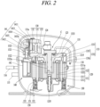
- FIG. 2 is a sectional view illustrating an inside of the reciprocating compressor of FIG. 1 .
- the reciprocating compressor includes a shell 110 defining an outer appearance, a motor unit 120 included in an inner space 110a of the shell 110 and configured to provide driving force, a compression unit 130 configured to receive the driving force from the motor unit 120 and compress refrigerant, a suction/discharge unit 140 configured to guide the refrigerant to a compression chamber and discharge the compressed refrigerant, and support portions 150 configured to support a compressor main body C including the motor unit 120 and the compression unit 130 with respect to the shell 110.
- the shell 110 includes a lower shell 111 and an upper shell 112.
- the lower shell 111 and the upper shell 112 can be combined to each other to define the inner space 110a which is enclosed.
- the motor unit 120 and the compression unit 130 can be accommodated in the inner space 110a of the shell 110.
- the shell 110 can be made of an aluminum alloy (hereinafter, abbreviated as aluminum) having a light weight and a high thermal conductivity.
- the lower shell 111 can be configured to have an approximately hemispherical shape.
- a suction pipe 115, a discharge pipe 116, and a process pipe can penetrate and be coupled into the lower shell 111.
- the suction pipes 115, the discharge pipes 116, and the process pipes can each be coupled into the lower shell 111 using an insert die casting method.
- the upper shell 112 can be configured to have an approximately hemispherical shape like the lower shell 111.
- the upper shell 112 can be coupled to the lower shell 1 1 1 on an upper side of the lower shell 1 1 1 to define the inner 110a of the shell 110 described above.
- the upper shell 112 and the lower shell 111 can be combined with each other by welding.
- the lower shell 111 and the upper shell 112 can be fastened with bolts.
- the motor unit (or driving motor) 120 can include a stator 121 and a rotor 122.
- the stator 121 can be elastically supported against the inner space 110a of the shell 110, i.e., a bottom surface of the lower shell 111, and the rotor 122 can rotatably equipped inside the stator 121.
- the stator 121 can include a stator core 1211 and a stator coil 1212.
- the stator core 1211 is made of a metal material such as an electrical steel sheet, and when a voltage is applied to the motor unit 120 from outside, performs an electromagnetic interaction through electromagnetic force together with the stator coil 1212, which will be described later, and the rotor 122.
- the stator core 1211 is configured to have a shape of approximately a rectangular box and/or a hollow hexahedron.
- an inner circumferential surface of the stator core 1211 can be configured to have a circular shape, and an outer circumferential surface thereof can be configured to have an approximately rectangular shape.
- the stator core 1211 can be coupled to a support plate 133, which will be described later, by stator fastening members 1215 to be elastically supported by the shell 110.
- first fastening holes 1211a are disposed through corners of the stator core 1211 along an axial direction of a drive shaft 125, respectively, and the stator fastening members 1215 configured to fasten support portions 1336 of the support plate 133, which will be described later, to the stator core 1211 can be inserted into the first fastening holes 1211a, respectively.
- stator fastening members 1215 can be fastened into the first fastening holes 1211a in the support portions 1336, which will be described later, by penetrating through the first fastening holes 1211a, or fastened into the first fastening holes 1211a in one side surface (an upper surface) of each of the support portions 1336 facing away from the stator core 1211 using a nut, etc. by sequentially penetrating through the first fastening holes 1211a.
- the stator core 1211 will be described later together with the support plate 133.
- stator core 1211 When the stator core 1211 is spaced apart from an inner surface of the shell 110 in an axial direction and a radial direction of the drive shaft 125, a lower end of the stator core 1211 can be supported by a support spring 151, which will be described later, with respect to a bottom surface of the shell 110. Accordingly, vibration generated during operation can be suppressed from being directly transmitted to the shell 110.
- the stator coil 1212 can be wound inside the stator core 1211. As described above, when a voltage is applied from outside, the stator coil 1212 generates electromagnetic force to perform an electromagnetic interaction together with the stator core 1211 and the rotor 122. By doing so, the motor unit 120 generates a driving force for a reciprocating motion of the compression unit 130.
- the rotor 122 includes a rotor core 1221 and a magnet 1222.
- the rotor core 1221 is made of a metal material such as an electrical steel sheet like the stator core 1211, and can be configured to have an approximately cylindrical shape.
- the drive shaft 125 can be press-fitted into a center of the rotor core 1221.
- the magnet 1222 is made of a permanent magnet and can be inserted to be coupled at equal intervals along a circumferential direction of the rotor core 1221.
- the rotor 122 rotates through electromagnetic interaction with the stator core 1211 and the stator coil 1212. Accordingly, the drive shaft 125 rotates together with the rotor 122 to transmit rotational force of the motor unit 120 to the compression unit 130 through a connecting rod 126.
- the compression unit 130 can include a valve assembly 141, a cylinder block 132, and the support plate 133.
- the piston 131 is a member coupled to the drive shaft 125 by the connecting rod 126 to perform a reciprocating motion.
- the cylinder block 132 is a member into which the piston 131 is inserted to perform a reciprocating motion and define a compression chamber 130a.
- the support plate 133 is a member disposed between the stator 121 and the cylinder block 132 to fix the cylinder block 132 to the stator 121.
- a side (a rear side) of the piston 131 facing toward the connecting rod 126 can be open, whereas an opposite side (a front side) facing away from the connecting rod 126 can have a closed and flat shape. Accordingly, the connecting rod 126 is inserted and rotatably coupled into a rear side of the piston 131, and a front side of the piston 131 defines the compression chamber 130a inside a cylinder portion 1323 together with a valve assembly 141, where the cylinder portion 1323 and the valve assembly 141will be described later.
- the cylinder block 132 can include a frame portion 1321, a bearing portion 1322, and the cylinder portion (cylinder) 1323.
- the frame portion 1321 connects the bearing portion 1322 to the cylinder portion 1323 to be supported on the support plate 133 which is to be described later in an axial direction of the drive shaft 125.
- the bearing portion 1322 includes a bearing hole 1322a to support the drive shaft 125 in a radial direction.
- the cylinder portion 1323 can extend from the frame portion 1321 to define the compression chamber 130a together with the piston 131.
- the frame portion 1321 of the cylinder block 132 is configured to have a thin and narrow shape. Accordingly, as volume of the cylinder block 132 can be decreased, a weight of the compression unit 130 including the cylinder block 132 can be reduced.
- the cylinder block 132 will be described later together with the support plate 133.
- the support plate 133 can include a block support surface portion 1331 and a block support protrusion 1332.
- the cylinder block 132 can be placed on the block support surface portion 1331 and supported in an axial direction of the drive shaft 125.
- the block support protrusion 1332 can extend from the block support surface portion 1331 and be placed on the stator core 1211 to be supported in an axial direction of the drive shaft 125. Accordingly, a weight of the cylinder block 132 including the support plate 133 can be reduced by replacing a part of the cylinder block 132 manufactured by casting with the support plate 133 obtained by performing sheet metal work.
- the support plate 133 will be described later together with the stator 121 and the cylinder block 132.
- the suction/discharge unit 140 can include the valve assembly 141, a suction muffler 142, and a discharge muffler 143.
- the valve assembly 141 and the suction muffler 142 can be sequentially coupled from an open end of the cylinder portion 1323.
- the valve assembly 141 can include a valve plate 1411, the suction valve 1412, a discharge valve 1414, a discharge valve stopper 1415, and a discharge cover 1416. In some examples, the valve assembly 141 can further include a gasket between the respective members described above.
- the valve plate 1411 can be configured to have an approximately rectangular plate shape and installed to cover a front end surface of the cylinder block 132, i.e., one open side surface of the compression chamber 130a.
- fastening holes can be disposed at corners of the valve plate 1411, respectively, to be bolted into fastening grooves (no reference numeral) disposed in the front end surface of the cylinder block 132.
- the valve plate 1411 can be equipped with both side surfaces having an approximately flat shape, and a center portion having one suction port 1411a and one discharge port 1411b disposed therein. However, in some cases, a plurality of suction ports 1411a and/or discharge ports 1411b can be disposed.
- the suction valve 1412 is configured as a rectangular plate made of a thin steel plate having elasticity, and can be placed on a side facing toward the piston 131, with reference to the valve plate 1411, i.e., on a rear side surface. Accordingly, the suction valve 1412 can open or close the suction port 1411a by being bent in a direction toward the piston 131.
- the discharge valve 1414 can be configured as a long plate made of a thin steel plate and placed on a front side surface of the valve plate 1411. Accordingly, the discharge valve 1414 can open or close the discharge port 1411b by being curved in a direction away from the piston 131.
- the discharge valve stopper 1415 can be configured as a rigid body and disposed between the discharge valve 1414 and the discharge cover 1416. One end of the discharge valve stopper 1415 can be in close contact with the discharge valve 1414, and another end thereof can be spaced apart from the discharge valve 1414 by a preset distance. Accordingly, the discharge valve stopper 1415 can press and fix the discharge valve 1414 onto the valve plate 1411 and, simultaneously, limit an opening amount of the discharge valve 1414.
- the discharge cover 1416 can be fastened to a front end surface of the cylinder block 132 to have the valve plate 1411 and the suction valve 1412 interposed therebetween to thereby ultimately cover the compression chamber 130a.
- the discharge cover 1416 can also be referred to as a cylinder cover. Accordingly, as the discharge valve 1414 is opened, refrigerant discharged from the compression chamber 130a through the discharge port 1411b can move to the discharge muffler 143 via the discharge cover 1416.
- the suction muffler 142 can be fixed by the valve assembly 141 to communicate with the suction port 1411a of the valve plate 1411.
- a suction space portion (no reference numeral) can be disposed in the suction muffler 142, and an inlet of the suction space portion can communicate directly or indirectly with the suction pipe 115, and an outlet of the suction space portion can directly communicate with a suction side of the valve assembly 141. Accordingly, the suction muffler 142 can transmit refrigerant suctioned through the suction pipe 115 to the compression chamber 130a of the cylinder portion 1323.
- the discharge muffler 143 can be equipped to be separate from the cylinder block 132.
- a discharge space portion (no reference numeral) can be disposed in the discharge muffler 143.
- An inlet of the discharge space portion can be connected to a discharge side of the valve assembly 141 by a loop pipe 118.
- An outlet of the discharge space portion can be directly connected to the discharge pipe 116 by the loop pipe 118. Accordingly, the discharge muffler 143 can attenuate a pressure pulsation of refrigerant discharged from the compression chamber 130a, and discharge the refrigerant to outside of the compressor through the discharge pipe 116.
- the support portions 150 support a space between a lower surface of the motor unit 120 and a bottom surface of the lower shell 111 facing the lower surface of the motor unit 120.
- the support portions 150 generally support four corners of the motor unit 120 against the shell 110.
- the support portions 150 can each include the support spring 151, and a first spring cap 152 and a second spring cap 153 both supporting a lower end of the support spring 151.
- an undescribed reference numeral 1255 denotes an oil feeder.
- the reciprocating compressor operates as described below.
- volume of the compression chamber 130a increases.
- refrigerant filled in the suction muffler 142 passes through the suction valve 1412 of the valve assembly 141 to be suctioned into the compression chamber 130a of the cylinder portion 1323.
- volume of the compression chamber 130a decreases.
- refrigerant filled in the compression chamber 130a is compressed, passes through the discharge valve 1414 of the valve assembly 141, and is discharged into the discharge chamber 1416a of the discharge cover 1416.
- the discharged refrigerant flows into the discharge space portion of the discharge muffler 143 through the loop pipe 118, and is discharged back through the loop pipe 118 and the discharge pipe 116 as a refrigeration cycle. This series of process is repeatedly performed.
- the compression unit 130 is coupled to the motor unit 120 as described above and constitute the compressor main body C together with the motor unit 120 to be elastically supported by the support portion 150 including the support spring 151.
- a weight of the compressor main body C can be reduced by reducing a weight of the motor unit 120 and/or the compression unit 130.
- the compressor can have a small size and/or a light weight, and compressor vibration can be reduced to allow to perform high load operation (high pressure and/or high-speed operation).
- a volume of a cylinder block constituting a part of a compression unit can be decreased to reduce a weight and/or a size of a compressor main body and a reciprocating compressor including the compressor main body.
- FIG. 3 is an exploded perspective view of a compressor main body.
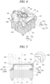
- FIG. 4 is an assembled perspective view illustrating the compressor main body of FIG. 3 .
- FIG. 5 is a front view of FIG. 4 .
- FIG. 6 is a side view of FIG. 4 .
- FIG. 7 is a plan view of FIG. 4 .
- FIG. 8 is a sectional view taken along line "IX-IX" of FIG. 7 .
- the compression unit 130 can include the piston 131, the cylinder block 132, and the support plate 133 as described above.
- the piston 131 can be coupled to the drive shaft 125 by the connecting rod 126 to be slidably inserted into the cylinder portion 1323.
- the cylinder block 132 can be coupled to the support plate 133 to be supported in an axial direction of the drive shaft 125.
- the support plate 133 can be coupled to the stator 121 to be supported in an axial direction of the drive shaft 125. Accordingly, the cylinder block 132 can be coupled to the stator 121 by the support plate 133 to be elastically supported by the shell 110.
- the piston 131 can be manufactured by casting.
- the cylinder block 132 can be configured as a single body in which the frame portion 1321, the bearing portion 1322, and the cylinder portion 1323, which will be described later, are manufactured by casting. Accordingly, perpendicularity between the bearing portion 1322 and the cylinder portion 1323 can be secured, and at the same time, roundness in the bearing portion 1322 and the cylinder portion 1323 can be secured. Thus, behavior of the piston 131 can be stabilized, and at the same time, the drive shaft 125 can be stably supported.
- the cylinder block 132 can include the frame portion 1321, the bearing portion 1322, and the cylinder portion (or cylinder) 1315 as described above.
- the frame portion 1321 can extend in a transverse direction perpendicular to an axial direction of the drive shaft 125.
- the bearing portion 1322 can extend from a center of the frame portion 1321 in an axial direction of the drive shaft 125.
- the cylinder portion 1323 can extend from one side of the frame portion 1321 in a radial direction of the drive shaft 125.
- the frame portion 1321 can be configured to have a flat plate shape extending in a radial direction (a transverse direction) of the drive shaft 125 or a radiating plate shape obtained by performing a slimming processing on some edges excluding corners.
- the frame portion 1321 can be configured to have a radiating plate shape having portions of corners extending longitudinally in a radial direction, and second fastening holes 1321a can be disposed through the corners of the frame portion 1321, respectively.
- the second fastening holes 1321a can be disposed coaxially with a third fastening hole 1331a disposed through the block support surface portion 1331 of the support plate 133, which will be described later, in an axial direction of the drive shaft 125.
- the frame portion 1321 can be fastened by a block fastening member 135, such as a bolt and/or a rivet, penetrating through the second fastening hole 1321a and the third fastening hole 1331a.
- a block fastening member 135, such as a bolt and/or a rivet penetrating through the second fastening hole 1321a and the third fastening hole 1331a.
- the frame portion 1321 can be configured to have approximately a constant thickness except for a portion on which the cylinder portion 1323 is disposed.
- the corner portions of the frame portion 1321 fastened to the support plate 133 can be configured to have an almost flat shape. Accordingly, whole volume of the cylinder block 132 including the frame portion 1321 can be decreased, thereby reducing a whole weight of the cylinder block 132 manufactured by casting.
- the bearing portion 1322 can be disposed to extend from a center portion of the frame portion 1321 along an axial direction of the drive shaft 125. In other words, the bearing portion 1322 can extend longitudinally toward the motor unit 120 to overlap the stator coil 1212 in a radial direction.
- the bearing hole 1322a can be disposed through the bearing portion 1322 along an axial direction of the drive shaft 125 to have a hollow shape.
- the drive shaft 125 can be supported at an upper end of the bearing portion 1322 in an axial direction, and a bearing portion (no reference numeral) of the drive shaft 125 can be supported on an inner circumferential surface of the bearing portion 1322 in a radial direction of the drive shaft 125. Accordingly, the drive shaft 125 can be supported by the cylinder block 132 in axial and radial directions of the drive shaft 125.
- the cylinder portion 1323 can be disposed to extend from one side edge of the frame portion 1321 along a radial direction of the drive shaft 125.
- the cylinder portion 1323 can extend as a single body from the frame portion 1321 and be disposed eccentrically from a center of the frame portion 1321 in a radial direction of the drive shaft 125.
- the cylinder portion 1323 can be penetrated in a radial direction of the drive shaft 125 to have an inner open end into which the piston 131 connected to the connecting rod 126 is inserted and an outer open end equipped with the valve assembly 141 constituting the suction/discharge unit 140 which will be described later. Accordingly, the cylinder portion 1323 can be configured to have a thickness greater than that of the frame portion 1321.
- the support plate 133 can be manufactured separately from the cylinder block 132, and then, assembled as described above. Accordingly, the support plate 133 can be made of various materials and/or shapes.
- the support plate 133 can be manufactured of a material same as or different from that of the cylinder block 132.
- the cylinder block 132 can be made of cast iron
- the support plate 133 can be made of an aluminum alloy, which is lighter than cast iron.
- the support plate 133 can be manufactured by casting or can also be made by sheet metal processing. In some examples, an example in which the support plate 133 is manufactured by sheet metal processing is mainly described. When the support plate 133 is processed into sheet metal, the support plate 133 can be easily machined.
- the support plate 133 can be made by bending a plate material having a same thickness according to a predetermined shape.
- the block support protrusion 1332 which will be described later, can be configured to have a same thickness as that of the block support surface portion 1331. Accordingly, not only a shape of the cylinder block 132 can be simplified, but also volume of the cylinder block 132 can be decreased, thereby reducing a whole weight of the compression unit 130.
- the support plate 133 can include the block support surface portion 1331 (or a first block support portion) and a plurality of block support protrusions 1332 (or second block support portions).
- the block support surface portion 1331 is a portion on which the cylinder block 132 is placed to be supported in an axial direction of the drive shaft 125.
- the plurality of block support protrusions 1332 are portions having end portions placed on an axial side surface (hereinafter used interchangeably with an upper side surface) of the stator core 1211 to be supported.
- the support plate 133 can constitutes a part of the compression unit 130 to be disposed between the compression unit 130 and the motor unit 120, e.g., between the cylinder block 132 and the stator 121 to couple the cylinder block 132 to the stator 121.
- the block support surface portion 1331 can be configured to have various shapes.
- the block support surface portion 1331 can be configured to have a " " shape (e.g., a bracket shape) or a "C" shape (e.g., a rotated "U” shape) similar thereto, when projected in an axial direction of the drive shaft 125.
- the block support surface portion 1331 can be configured to have an arc shape with both ends by being secondarily bent along a circumferential direction.
- a bearing accommodating portion 1331b is disposed at a center of the block support surface portion 1331 to penetrate therethrough in an axial direction of the drive shaft 125 to surround and accommodate the bearing portion 1322 of the cylinder block 132.
- a cylinder accommodating portion 1331c can be disposed to be open on one side of the bearing accommodating portion 1331b in a radial direction to accommodate the cylinder portion 1323. By doing so, the block support surface portion 1331 can overlap the cylinder portion 1323 in an axial direction of the drive shaft 125.
- the frame portion 1321 of the cylinder block 132 which will be described later, can have a small thickness, thereby reducing volume of the cylinder block 132.
- the block support surface portion 1331 can be disposed to at least partially overlap the stator coil 1212 of the stator 121 in an axial direction of the drive shaft 125.
- an inner circumferential surface of the block support surface portion 1331 can be disposed to be located within a range of a radial direction of the stator coil 1212. Accordingly, deformation of the block support surface portion 1331 can be suppressed by securing an appropriate width of the block support surface portion 1331.
- the third fastening hole 1331a corresponding to the second fastening hole 1321a in the cylinder block 132 described above can be disposed in the block support surface portion 1331.
- the third fastening hole 1331a can be disposed through corners of the block support surface portion 1331 to penetrate through an axial direction of the drive shaft 125 and be located on a same axial line as that of the second fastening hole 1321a. Accordingly, the block support surface portion 1331 can be firmly coupled to the frame portion 1321 of the cylinder block 132 by the block fastening member 135 inserted into the second fastening hole 1321a and the third fastening hole 1331a.
- one of the second fastening hole 1321a and the third fastening hole 1331a described above can be configured as a caulking protrusion to be caulked to the frame portion 1321 in a state of being inserted into a fastening hole (or a fastening groove) at an opposite side. This will be described again later.
- a stopper protrusion 1333 supporting the cylinder block 132 in a radial direction of the drive shaft 125 can be disposed on the block support surface portion 1331 to protrude in an axial direction of the drive shaft 125.
- the stopper protrusion 1333 can be disposed to be bent from an inner circumferential surface of the bearing accommodating portion 1331b toward a side opposite to the motor unit 120 and at least partially located on the first center line CL1 (see FIG. 7 ) passing through a center of the cylinder portion 1323 when being axially projected in an axial direction (or along a shaft axis) of the drive shaft 125. Accordingly, when the piston 131 moves backward (suction stroke), force transmitted to the cylinder block 132 can be attenuated to stably support the cylinder block 132.
- the stopper protrusion 1333 can be configured to have a flat shape extending along an axial direction of the drive shaft 125.
- the stopper protrusion 1333 can be also configured to be bent to have a shape of " " (e.g., a rotated "L” shape) toward the cylinder portion 1323 of the cylinder block 132 as shown in FIG. 8 .
- the stopper protrusion 1333 can support one side surface (an upper side surface) of the frame portion 1321 in an axial direction of the drive shaft 125.
- the frame portion 1321 of the cylinder block 132 can be supported by the stopper protrusion 1333 in radial and axial directions of the drive shaft 125 to be firmly coupled to the cylinder block 132 and the support plate 133.
- the stopper protrusion 1333 supports the cylinder block 132 in a reciprocating direction of the piston 131, the cylinder block 132 can be suppressed from being pushed away from the support plate 133 due to repetitive reciprocating motions of the piston 131 to stably support radial and/or axial directions of the cylinder block 132.
- the plurality of block support protrusions 1332 can be disposed to be bent from respective corners of the block support surface portion 1331 having a"c" shape (e.g., a bracket shape) toward the stator core 1211.
- a center line in a reciprocating direction of the piston 131 is referred to as a first center line CL1 and a center line passing through an axial center Os of the drive shaft 125 and perpendicular to the first center line CL1 is referred to a second center line CL2 (see FIG. 7 )
- the plurality of block support protrusions 1332 can be disposed at positions symmetrical to each other with reference to the first center line CL1 and positions symmetrical to each other with reference to the second center line CL2, respectively.
- the plurality of block support protrusions 1332 can be configured to be disposed at same or almost similar positions in all directions from a center Os (e.g., an axial center, or a center axis) of the frame portion 1321, respectively. Accordingly, as the plurality of block support protrusions 1332 are arranged radially from a center of the frame portion 1321, support force of the support plate 133 can be uniformly distributed to stably support the cylinder block 132. In addition, as the block support protrusions 1332 are disposed widely as possible on the block support surface portion 1331, the cylinder block 132 can be stably supported.
- a center Os e.g., an axial center, or a center axis
- the plurality of block support protrusions 1332 can each include one bent portion 1335 and one support portion 1336.
- the bent portion 1335 is a portion primarily bent in the block support surface portion 1331.
- the support portion 1336 is a portion secondarily bent in the bent portion 1335.
- the block support protrusion 1332 can be bent in two steps from the block support surface portion 1331 to have a sectional shape of "L" when projected from a front. Accordingly, as a large area of the block support protrusion 1332 in contact with an axial side surface (an upper side surface) of the stator core 1211 is secured, the cylinder block 132 can be stably supported.
- a plurality of bent portions 1335 can be each configured such that one end is bent from an outer circumferential surface of the block support surface portion 1331 along an axial direction (or longitudinal direction) of the drive shaft 125.
- the bent portions 1335 can be bent at a right angle toward an axial side surface (an upper side surface) of the stator core 1211 from respective corners including both ends of the block support surface portion 1331 having a "c" shape (e.g., a bracket shape). Accordingly, the block support surface portion 1331 can be located above the stator coil 1212 to, in correspondence with this, reduce volume of the support plate 133.
- a height of the bent portions 1335 can be configured to be slightly greater than a height at which the stator coil 1212 protrudes from an axial side surface (an upper side surface) of the stator core 1211.
- the height of the bent portions 1335 can be greater than the height of the stator coil 1212 protruding from the axial side surface of the stator core 1211 by a predetermined amount.
- the bent portions 1335 can be configured such that the block support surface portion 1331 is slightly spaced apart from the stator coil 1212 in a state when the support portion 1336, which will be described later, is placed on an axial side surface (an upper side surface) of the stator core 1211. Accordingly, buckling of the bent portions 1335 can be effectively suppressed by minimizing a height of the bent portions 1335, even when the cylinder block 132 is placed on the block support surface portion 1331.
- the bent portions 1335 can each have at least one reinforcement rib 1337 disposed on a bent or curved portion from the block support surface portion 1331.
- a first bending line 1335a from the block support surface portion 1331 and a second bending line 1335b from the support portion 1336 can be disposed at both ends of each of the bent portions 1335.
- the at least one reinforcement rib 1337 described above can be disposed at the first bending line 1335a and/or the second bending line 1335b.
- the reinforcement rib 1337 can be obtained by post-assembling a separate member by welding, etc., but can be obtained by performing caulking on inside of a portion bent from the first bending line 1335a and/or the second bending line 1335b as shown in FIG.
- the reinforcement rib 1337 is disposed on the first bending line 1335a, but the reinforcement rib 1337 can be also disposed identically on the second bending line 1335b. Accordingly, even when the block support protrusions 1332 including the bent portions 1335 are bent from the block support surface portion 1331, since rigidity of the block support protrusions 1332 is increased, the cylinder block 132 can be stably supported.
- the plurality of bent portions 1335 can each be configured by being bent twice or more. In other words, the plurality of bent portions 1335 can be configured by being bent to have multiple steps. In this case, the reinforcement rib 1337 can be also disposed at each bent portion.
- each of a plurality of support portions 1336 can be configured by being bent (in a transverse direction) from an end of each of the bent portions 1335, the end opposite to the block support surface portion 1331 along an axial side surface (an upper side surfaces) of the stator core 1211 (in a traverse direction).
- the plurality of support portions 1336 can be disposed by being bent from the respective bent portions 1335 in a same direction as a reciprocating direction of the piston 131. Accordingly, as a bending operation on the support portions 1336 is simplified, machinability of the support plate 133 including the support portions 1336 can be enhanced.
- the plurality of support portions 1336 can be configured to be bent symmetrically with reference to the first center line CL1, and bent asymmetrically with reference to the second center line CL2.
- a first support portion 1336a located on a side on which the cylinder portion 1323 is disposed with reference to the second center line CL2 can be bent to face toward an inner circumferential surface of the shell 110
- a second support portion 1336b located on an opposite side to the cylinder portion 1323 can be bent to face away from an inner circumferential surface of the shell 110.
- the cylinder portion 1323 can be disposed at a first side with respect to axial center axis Os of the rotor that is perpendicular to the reciprocating direction of the piston.
- the support portions 1336 can include the first support portion 1336a disposed at the first side with respect to the axial center axis Os of the rotor and is bent in a direction (e.g., left) toward an inner circumferential surface of the shell facing the cylinder portion 1323 in the reciprocating direction of the piston, and the second support portion 1336b that is disposed at a second side with respect to the axial center axis Os of the rotor opposite to the first side and is bent in the direction (i.e., left) toward the inner circumferential surface of the shell.
- the first support portion 1336a can be disposed at the first side with respect to the axial center axis Os of the rotor and is bent in a first direction (e.g., left) toward an inner circumferential surface of the shell facing the cylinder portion in the reciprocating direction of the piston
- the second support portion 1336b can be disposed at a second side with respect to the axial center axis Os of the rotor opposite to the first side and is bent in a second direction (e.g., right) away from the inner circumferential surface of the shell facing the cylinder portion 1323.
- the first support portion 1336a can be disposed at the first side with respect to the axial center axis Os of the rotor and is bent in a direction (e.g., right) away from an inner circumferential surface of the shell facing the cylinder portion 1323 in the reciprocating direction of the piston, and the second support portion 1336b is disposed at a second side with respect to the axial center axis Os of the rotor opposite to the first side and is bent in the direction (i.e., right) away from the inner circumferential surface of the shell.
- the first support portion 1336a can be disposed at the first side with respect to the axial center axis Os of the rotor and is bent in a first direction (e.g., right) away from an inner circumferential surface of the shell facing the cylinder portion in the reciprocating direction of the piston
- the second support portion 1336b can be disposed at a second side with respect to the axial center axis Os of the rotor opposite to the first side and is bent in a second direction (e.g., left) toward the inner circumferential surface of the shell facing the cylinder portion 1323.
- a second support length L2 to the second support portion 1336b can be greater than a first support length L1 to the first support portion 1336a with reference to the axial center Os.
- a support point for the cylinder block 132 on the opposite side to the cylinder portion 1323 is located far away from the axial center Os of the drive shaft 125, even when a center of gravity of the cylinder block 132 is eccentric toward the cylinder portion 1323 of the cylinder block 132, an overturning moment of the cylinder block 132 can be decreased.
- fourth fastening holes 1332a can be disposed through the plurality of support portions 1336, respectively, in an axial direction of the drive shaft 125.
- the fourth fastening holes 1332a can be disposed on a same axis as that of the first fastening holes 1211a in the stator core 1211 described above.
- the plurality of support portions 1336 can be coupled to the stator core 1211 by the stator fastening members 1215 (e.g., fastening bolts and/or fastening rivets) having a great length and passing through the first fastening holes 1211a and the fourth fastening holes 1332a. This can simplify an operation of assembling the support plate 133 with the stator 121 to thereby reduce a manufacturing process.
- volume of the cylinder block 132 can be decreased to reduce a whole weight of the compression unit 130. Accordingly, not only a weight of the compressor main body C is reduced, but also a load on the support portion 150 supporting the compressor main body C can be reduced, thereby reducing a size of the compressor. In addition, vibration generated during operation of operation of a compressor can be reduced to allow operation in various fields including high load operation.
- a portion manufactured by casting can be minimized to easily manufacture the cylinder block 132 including the cylinder portion 1323 while reducing a weight.
- the cylinder block 132 is coupled to the stator 121 using the support plate 133 that is post-assembled, even when a fixing protrusion configured to fix the cylinder block 132 to the stator 121 is excluded from the cylinder block 132, the cylinder block 132 can be stably coupled to the stator 121.
- a separate support plate 133 can be disposed between the cylinder block 132 and the stator 121, but the cylinder block 132 can be easily assembled onto the stator 121.
- the bearing portion 1322 and the cylinder portion 1323 are configured as a single body in the cylinder block 132, perpendicularity between the bearing portion 1322 and the cylinder portion 1323 can be maintained, and at the same time, roundness in the bearing portion 1322 and the cylinder portion 1323 can be secured, thereby increasing compression efficiency and/or reliability.
- a support portion of a support plate located on a side on which a cylinder portion is disposed in a cylinder block is bent in a direction facing toward an inner circumferential surface of a shell.
- a support portion of a support plate located on a side on which a cylinder portion is located in the cylinder block can be bent in a direction facing away from an inner circumferential surface of the shell.
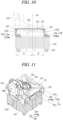
- FIG. 9 is a perspective view illustrating an example of a support plate.
- FIG. 10 is a front view of FIG. 9 .
- the compression unit 130 can include a piston 131, a cylinder block 132, and a support plate 133, and the cylinder block 132 can be coupled to a stator 121 by the support plate 133 to be supported in an axial direction of the drive shaft 125. Accordingly, volume of the cylinder block 132 can be decreased, thereby reducing a weight of the cylinder block 132 and the compression unit 130 including the same.
- the cylinder block 132 can include a frame portion 1321, a bearing portion 1322, and a cylinder portion 1323.
- the frame portion 1321, the bearing portion 1322, and the cylinder portion 1323 can be manufactured by casting to be configured as a single body. Accordingly, perpendicularity between the bearing portion 1322 and the cylinder portion 1323 each included in the cylinder block 132 can be maintained, and at the same time, roundness thereof can be also secured.
- the support plate 133 can include a block support surface portion 1331 and a plurality of block support protrusions 1332.
- the block support surface portion 1331 and the plurality of block support protrusions 1332 can be manufactured of sheet metal to be configured as a single body.
- the block support surface portion 1331 can have an approximately " " shape (e.g., a bracket shape), and the plurality of block support protrusions 1332 can be disposed to be bent from respective corners including both ends of the block support surface portion 1331 toward the stator 121, respectively.
- the plurality of block support protrusions 1332 can include a plurality of bent portions 1335 each bent from the block support surface portion 1331 toward an axial side surface (an upper side surface) of the stator 121, and a plurality of support portions 1336 bent from the plurality of bent portions 1335, respectively, along an axial side surface of the stator 121. Accordingly, even when the support plate 133 is manufactured of sheet metal, the cylinder block 132 can be stably supported on the stator 121.
- a support portion 1336 located on a side on which the cylinder portion 1323 is located i.e., a first support portion 1336a located on the side on which the cylinder portion 1323 is disposed with reference to the second center line CL2 of FIG. 7 can be bent in a direction facing away from an inner circumferential surface of the shell 110.
- block support protrusions 1332 bent on the side on which the cylinder portion 1323 is disposed may be located farther away from a center of the cylinder block 132, i.e., the second center line CL2 (or an axial center), compared to those in the above-described implementation of FIG. 3 .
- the plurality of bent portions 1335 can be bent in a position adjacent to a front-end surface of the cylinder portion 1323 as possible.
- a first support length L1 to the first support portion 1336a is increased, whereas a second support length L2 to a second support portion 1336b can be decreased. Accordingly, since a center of the block support surface portion 1331 moves toward the cylinder portion 1323, the cylinder portion 1323 relatively heavy in the cylinder block 132 can be stably supported.
- a support portion 1336 located on a side opposite to the cylinder portion 1323 i.e., the second support portion 1336b located on the opposite side to the cylinder portion 1323 with reference to the second center line CL2 can be bent in a direction facing toward an inner circumferential surface of the shell 110.
- a geometric center of the support plate 133 can be moved toward the cylinder portion 1323 while a lateral length of the block support surface portion 1331 is maintained. Accordingly, the cylinder block 132 can be stably supported while a weight of the support plate 133 is maintained.
- support portions of a support plate are bent in a same direction. In some implementations, support portions of a support plate can be bent in directions different from each other.
- FIG. 11 is a perspective view illustrating an example of a support plate.
- FIG. 12 is a front view of FIG. 11 .
- the compression unit 130 can include a piston 131, a cylinder block 132, and a support plate 133, and the cylinder block 132 can be coupled to a stator 121 by the support plate 133 to be supported in an axial direction of a drive shaft 125. Accordingly, volume of the cylinder block 132 can be decreased, thereby reducing a weight of the cylinder block 132 and the compression unit 130 including the same.
- the cylinder block 132 includes a frame portion 1321, a bearing portion 1322, and a cylinder portion 1323.
- the frame portion 1321, the bearing portion 1322, and the cylinder portion 1323 can be manufactured by casting to be configured as a single body. Accordingly, perpendicularity between the bearing portion 1322 and the cylinder portion 1323 each included in the cylinder block 132 can be secured, and at the same time, roundness thereof can be also secured.
- the support plate 133 can include a block support surface portion 1331 and a plurality of block support protrusions 1332.
- the block support surface portion 1331 and the plurality of block support protrusions 1332 can be manufactured of sheet metal to be configured as a single body.
- the block support surface portion 1331 can have an approximately " " shape (e.g., a bracket shape), and the plurality of block support protrusions 1332 can be disposed to be bent from respective corners including both ends of the block support surface portion 1331 toward the stator 121, respectively.
- the plurality of block support protrusions 1332 can include a plurality of bent portions 1335 each bent from the block support surface portion 1331 toward an axial side surface (an upper side surface) of the stator 121, and a plurality of block support portions 1336 bent from the plurality of bent portions 1335, respectively, along an axial side surface of the stator 121. Accordingly, even when the support plate 133 is manufactured of sheet metal, the cylinder block 132 can be stably supported on the stator 121.
- the plurality of support portions 1336 are disposed symmetrically with reference to the second center line CL2 of FIG. 7 , and each of the plurality of support portions 1336 can be bent to face away from an inner circumferential surface of the shell 110.
- a first support portion 1336a located on a side on which the cylinder portion 1323 is disposed and a second support portion 1336b located on a side opposite to the cylinder portion 1323 can be respectively bent in a direction facing away from an inner circumferential surface of the shell 110.
- both block support protrusions 1332 bent on the side on which the cylinder portion 1323 is disposed and block support protrusions 1332 bent on the opposite side to the cylinder portion 1323 are located far away from the second center line CL2 (or an axial center).
- the plurality of bent portions 1335 can be bent from the block support surface portion 1331 at positions far away from the second center line CL2 as possible.
- a first support length L1 to the first support portion 1336a and a second support length L2 to the second support portion 1336b with reference to an axial center Os can be increased toward both sides.
- a length of the block support surface portion 1331 is increased, and in correspondence with this, support force with respect to the cylinder block 132 can be provided widely. Accordingly, an overturning moment of the cylinder block 132 can be decreased, thereby stably supporting the cylinder block 132.
- the plurality of support portions 1336 can be all bent in a direction toward an inner circumferential surface of the shell 110.
- the plurality of bent portions 1335 can be bent from the block support surface portion 1331 at positions adjacent to the second center line CL2 as possible. Accordingly, a length of the block support surface portion 1331 is decreased to a minimum, and in correspondence with this, a weight of the support plate 133 and the compression unit 130 including the support plate 133 can be reduced.
- the support plate 133 can be made by casting, other than by sheet metal processing.
- block support protrusions of a support plate are disposed to be symmetrical to each other.
- block support protrusions of a support plate can be disposed to be asymmetrical to each other.
- FIG. 13 is an exploded perspective view illustrating an example of a support plate.
- FIG. 14 is an assembled perspective view of FIG. 13 .
- FIG. 15 is a front view of FIG. 14 .
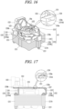
- FIG. 16 is a perspective view illustrating an example of the support plate.
- FIG. 17 is a front view of FIG. 16 .
- the compression unit 130 can include a piston 131, a cylinder block 132, and a support plate 133, and the cylinder block 132 can be coupled to a stator 121 by the support plate 133 to be supported in an axial direction of the drive shaft 125. Accordingly, volume of the cylinder block 132 can be decreased, thereby reducing a weight of the cylinder block 132 and the compression unit 130 including the same.
- the cylinder block 132 can include a frame portion 1321, a bearing portion 1322, and a cylinder portion 1323.
- the frame portion 1321, the bearing portion 1322, and the cylinder portion 1323 can be manufactured by casting to be configured as a single body. Accordingly, perpendicularity between the bearing portion 1322 and the cylinder portion 1323 each included in the cylinder block 132 can be maintained, and at the same time, roundness thereof can be also secured.
- the support plate 133 can include a block support surface portion 1331 and a plurality of block support protrusions 1332.
- the block support surface portion 1331 and the plurality of block support protrusions 1332 can be manufactured of sheet metal to be configured as a single body.
- the block support surface portion 1331 can have an approximately " " (e.g., a bracket shape) or "C" shape (e.g., a rotated U shape), and the plurality of block support protrusions 1332 can be disposed to be bent from corners of the block support surface portion 1331 and a portion between the corners, respectively, toward the stator 121.
- the plurality of block support protrusions 1332 can include a plurality of bent portions 1335 bent from the block support surface portion 1331 toward an axial side surface of the stator 121, and a plurality of support portions 1336 bent from the plurality of bent portions 1335, respectively, along an axial side surface of the stator 121. Accordingly, even when the support plate 133 is manufactured of sheet metal, the cylinder block 132 can be stably supported on the stator 121.
- the plurality of support portions 1336 can be disposed symmetrically with reference to the first center line CL1 and asymmetrically with reference to the second center line CL2, respectively.
- the plurality of support portions 1336 can be disposed symmetrically with reference to the first center line CL1 and the second center line CL2, respectively.
- the block support surface portion 1331 can be configured to have a "C" shape (e.g., a rotated U shape), and the plurality of block support protrusions 1332 can be disposed to be bent from corners of the block support surface portion 1331 and a portion between the corners, respectively, toward the stator 121.
- a first support portion 1336a located on a side on which the cylinder portion 1323 is disposed with reference to the second center line CL2 can be configured to be bent from both side corners of the block support surface portion 1331, i.e., both open ends constituting a cylinder accommodating portion 1331c.
- a second support portion 1336b disposed on a side opposite to the cylinder portion 1323 can be disposed to be bent from a portion between the both side corners, i.e., from a middle portion of the both side corners. Accordingly, in some implementations, a total of three block support protrusions 1332 can be disposed.
- the block support protrusions 1332 may not be bent directly from the block support surface portion 1331, but can be configured such that a first extension portion 1338a is further disposed between each of the block support protrusions 1332 and the block support surface portion 1331.
- a block support protrusion 1332 located on the opposite side to the cylinder portion 1323, among the block support protrusions 1332 can be configured such that the block support surface portion 1331 is extended in a radial direction in correspondence with a length of the first extension portion 1338a, and then, a bent portion 1335 is bent from an end of the first extension portion 1338a, the end opposite to the block support surface portion 1331, in an axial direction of the drive shaft 125. Accordingly, the block support surface portion 1331 can be shortened in correspondence with the length of the first extension portion 1338a, thereby reducing a weight of the support plate 133 including the block support surface portion 1331.
- the stator core 1211 can have an outer circumferential surface with a polyhedral shape, such as an approximately hexahedron, like the above-described implementations, and has a plate support protrusion 1211b disposed on a side surface opposite to the cylinder portion 1323 with reference to the second center line CL2 of FIG. 7 .
- the plate support protrusion 1211b can be disposed to extend in a radial direction to have a support portion 1336 of the block support protrusions 1332 placed thereon and supported in an axial direction of the drive shaft 125.
- a first fastening hole 1211a can be disposed through the plate support protrusion 1211b in an axial direction of the drive shaft 125 so that the stator fastening member 1215 is inserted into the first fastening hole 1211a. Accordingly, the plurality of block support protrusions 1332 can be coupled to the stator 121 using the stator fastening member 1215 configured to fasten the stator core 1211, like the above-described implementations.
- a stopper protrusion 1333 can be disposed on an inner circumferential surface of the block support surface portion 1331, i.e., on an inner circumferential surface of a bearing accommodating groove 1333b to protrude in an axial direction of the drive shaft 125, and a block protrusion 1324 of the cylinder block 132 can be disposed on the frame portion 1321 of the cylinder block 132 to protrude in an axial direction of the drive shaft 125 to face the stopper protrusion 1333 of the block support surface portion 1331 in a radial direction.
- the stopper protrusion 1333 and the block protrusion 1324 can be disposed to at least partially overlap each other on the first center line CL1 in FIG. 7 .
- the block protrusion 1324 of the cylinder block 132 can be supported in a radial direction by the stopper protrusion 1333 of the block support surface portion 1331. Accordingly, pushing of the cylinder block 132 in a radial direction which can be caused during a suction stroke of the piston 131 can be suppressed.
- stopper protrusion 1333 can be fastened to the block protrusion 1324 with a separate block fastening member 135 such as a bolt and/or a rivet.
- the stopper protrusion 1333 can be caulked to the block protrusion 1324.
- a caulking protrusion 1333a and/or a caulking groove 1324a are disposed on the stopper protrusion 1333 and/or the block protrusion 1324, respectively, to caulk the caulking protrusion 1333a into the caulking groove 1324a is illustrated. This also applies to the cylinder block 132 and the support plate 133.
- a plurality of caulking grooves 1321b can be disposed in one side surface of the cylinder block 132 facing the support plate 133, and a plurality of caulking protrusions 1331d (or caulking grooves) caulked into the caulking grooves 1321b in the cylinder block 132, respectively, can be disposed on one side surface of the support plate 133 facing the cylinder block 132. This can simplify a process of assembling between the cylinder block 132 and the support plate 133.
- second extension portions 1338b extending in a radial direction of the drive shaft 125 toward an inner circumferential surface of the shell 110 can be disposed at both ends of the block support surface portion 1331, respectively, and bent portions 1335 of the block support protrusions 1332, described above, can be disposed to be bent from the second extension portions 1338b toward the stator 121 in an axial direction of the drive shaft 125, respectively. Accordingly, a lateral space D in the block support surface portion 1331 becomes narrow, and in correspondence with this, a whole area of the block support surface portion 1331 is decreased, thereby reducing a weight of the support plate 133.
- the first extension portion 1338a can extend in a first direction along the radial direction
- the second extension portions 1338b can extend in a second direction different from the first direction
- a number of processes for coupling the support plate 133 to the stator 121 can be reduced in correspondence with a reduction in the number of block support protrusions 1332.
- a weight of the support plate 133 can be decreased in correspondence with a reduction in the number of block support protrusions 1332
- an area of the block support surface portion 1331 can be also decreased, thereby reducing a whole weight of the support plate 133.
- a weight of the cylinder block 132 can be reduced by simplifying a shape of the frame portion 1321 in the cylinder block 132.
- the block protrusion 1324 can be disposed on the frame portion 1321 of the cylinder block 132 to protruding from a side opposite to the cylinder portion 1323 in a radial direction of the drive shaft 125.
- the block protrusion 1324 can be placed on the block support surface portion 1331 and supported in the axial direction of the drive shaft 125 so that the cylinder block 132 can be stably supported on the support plate 133.
- the block protrusion 1324 and the stopper protrusion 1333 facing the same can be fastened with each other using the block fastening member 135 such as a rivet, or caulked with each other using a caulking protrusion and a caulking groove each disposed thereon. Accordingly, the cylinder block 132 can be effectively suppressed from being pushed against the support plate 133 in a reciprocating direction of the piston 131 during a compression stroke as well as a suction stroke of the piston 131.
Landscapes
- Engineering & Computer Science (AREA)
- Mechanical Engineering (AREA)
- General Engineering & Computer Science (AREA)
- Compressor (AREA)
- Compressors, Vaccum Pumps And Other Relevant Systems (AREA)
Abstract
A reciprocating compressor includes a shell, a driving motor, a drive shaft, a piston, a cylinder block, and a support plate disposed between the driving motor and the cylinder block to support the cylinder block with respect to the drive motor in an axial direction of the drive shaft. The support plate has one side surface coupled to the stator and another side surface coupled to the cylinder block. The reciprocating compressor is light-weighted and/or miniaturized by reducing a weight of the cylinder block, and perpendicularity and roundness with respect to the cylinder portion and the bearing portion is secured to improve reliability.
Description
- This disclosure relates to a reciprocating compressor.
- A reciprocating compressor may include a piston that suctions, compresses, and discharges refrigerant into a compression chamber, where the piston is disposed inside a cylinder while performing a reciprocating motion inside the cylinder. In some cases, the cylinder may be a part of a cylinder block manufactured by casting, and may be configured as a single body extending from a frame portion supporting a drive shaft in radial and axial directions of the drive shaft. In some cases, the cylinder may be defined as a cylinder portion, and disposed eccentrically in a radial direction of the drive shaft at one side of the frame portion that is a part of the cylinder block.
- In some cases, the cylinder block may be made by casting such that a bearing portion extending in an axial direction of the drive shaft to support the drive shaft in a radial direction is disposed at a center of the frame portion and a plurality of fixing protrusions are disposed at corners of the frame portion to protrude toward a stator in an axial direction of the drive shaft. Accordingly, the cylinder block may be coupled to the stator to be elastically supported against a shell.
- In some cases, a cylinder portion may be a single body integrally with a bearing portion supporting a drive shaft. This configuration may provide perpendicularity between the cylinder portion and the bearing portion and roundness of the cylinder portion. In some cases, a fixing protrusion for fastening a cylinder block to a stator may extend from a frame portion to constitute a single body integrally with the cylinder portion and the bearing portion. In some cases, a shape of the cylinder block including the cylinder portion, the bearing portion, the frame portion, and the fixing protrusion may be complicated, and a weight of the cylinder block may be increased, which may limit reduction of a weight and/or size of a compressor
- In some cases, a cylinder block may include a cylinder portion assembled to a frame portion. This configuration may variously change a shape of the cylinder block including the cylinder portion. In some cases, as a cylinder portion and a bearing portion are post-assembled, perpendicularity between the cylinder portion and the bearing portion and/or roundness of the cylinder portion may not be secured. In some cases, the frame portion and a fixing protrusion may be configured as one single body and manufactured by casting, which may still limit reduction of a weight and/or size of a compressor.
- The present disclosure describes a reciprocating compressor having an advantage in weight reduction and/or miniaturization.
- The present disclosure further describes a reciprocating compressor in which parts manufactured by casting can be minimized to easily manufacture and reduce a weight of a cylinder block including a cylinder portion.
- The present disclosure further describes a reciprocating compressor in which a fixing protrusion for fixing a cylinder block to a stator can be excluded from the cylinder block, but the cylinder block can be stably and easily coupled to the stator.
- The present disclosure further describes a reciprocating compressor in which perpendicularity between a cylinder portion and a bearing portion can be maintained, and simultaneously roundness of the cylinder portion can be secured.
- According to one aspect of the subject matter described in this application, a reciprocating compressor includes a shell, a driving motor that is disposed inside the shell and includes a stator and a rotor, a drive shaft coupled to the rotor of the driving motor, a piston coupled to the drive shaft and configured to perform a reciprocating motion, a cylinder block including (i) a cylinder portion that receives the piston and defines a compression chamber with the piston and (ii) a bearing portion that receives the drive shaft and supports the drive shaft in a radial direction of the drive shaft, and a support plate that is disposed between the driving motor and the cylinder block and supports the cylinder block from the driving motor in an axial direction of the drive shaft, where the support plate has one side surface coupled to the stator and another side surface coupled to the cylinder block. Thus, the reciprocating compressor can be light-weighted and/or miniaturized by reducing a weight of the cylinder block, and perpendicularity and roundness with respect to the cylinder portion and the bearing portion can be secured to improve reliability.
- Implementations according to this aspect can include one or more of the following features. For example, the support plate can include a first block support portion that supports the cylinder block in the axial direction of the drive shaft, and a plurality of second block support portions that are each bent or curved from the first block support portion toward the stator and disposed on the stator, where the stator supports the plurality of second block support portions in the axial direction of the drive shaft. Thus, the support plate can be made of sheet metal to easily manufacture the support plate, and a weight of the support plate can be reduced.
- In some implementations, the first block support portion and the plurality of second block support portions have a same thickness in the axial direction of the drive shaft. Thus, a shape of the cylinder block can be simplified, and a volume of the cylinder block can be decreased, thereby reducing a weight of a compression unit.
- In some implementations, the first block support portion can define a bearing accommodating portion that passes through the first block support portion in the axial direction of the drive shaft and surrounds at least a portion of the bearing portion, and a cylinder accommodating portion that is one open side of the bearing accommodating portion in the radial direction of the drive shaft and accommodates at least a portion of the cylinder portion. Thus, since the first block support portion can be configured to have an arc shape to overlap the cylinder portion in the axial direction of the drive shaft, a frame portion of the cylinder block can have a small thickness.
- In some implementations, each of the plurality of second block support portions can include a bent portion that is bent from the first block support portion toward an axial side surface of the stator and extends in the axial direction of the drive shaft, and a support portion that is bent from an end of the bent portion and extends along the axial side surface of the stator, the support portion being supported by the axial side surface of the stator in the axial direction of the drive shaft.. Thus, volume of the cylinder block can be reduced, and the cylinder block can be coupled to the stator by the support plate to be spaced apart from the stator by a preset height.
- In some examples, the compressor can include a plurality of stator fastening members that pass through the stator, each of the stator fastening members being coupled to the support portion of one of the plurality of second block support portions. Thus, assembly work on the stator and the support plate coupled to the stator can be unified to reduce a number of assembly processes.
- In some examples, the support portions can be bent from the bent portions, respectively, in a same direction along a reciprocating direction of the piston. Thus, bending work on the plurality of support portions can be simplified to improve machinability of the support plate including the plurality of support portions.
- For example, the cylinder portion can be disposed at a first side with respect to an axial center axis of the rotor that is perpendicular to the reciprocating direction of the piston, where the support portions includes a first support portion disposed at the first side with respect to the axial center axis of the rotor and is bent in a direction toward an inner circumferential surface of the shell facing the cylinder portion in the reciprocating direction of the piston, and a second support portion that is disposed at a second side with respect to the axial center axis of the rotor opposite to the first side and is bent in the direction toward the inner circumferential surface of the shell. Thus, fastening of the first support portion located on the side on which the cylinder portion is disposed can be simplified, and an overturning moment of the cylinder block can be decreased by securing a long support length of the support plate.
- In some examples, the first support portion can be disposed at the first side with respect to the axial center axis of the rotor and is bent in a direction away from an inner circumferential surface of the shell facing the cylinder portion in the reciprocating direction of the piston, and the second support portion can be disposed at a second side with respect to the axial center axis of the rotor opposite to the first side and is bent in the direction away from the inner circumferential surface of the shell. Thus, since a support length supporting the side on which the cylinder portion is disposed is configured to be great, the cylinder portion which is relatively heavy can be stably supported.
- In some implementations, the support portions are bent from the bent portions, respectively, in opposite directions to each other along a reciprocating direction of the piston. Thus, sheet metal work on the support plate can be easily performed.
- For example, in some examples, the first support portion can be disposed at the first side with respect to the axial center axis of the rotor and is bent in a first direction away from an inner circumferential surface of the shell facing the cylinder portion in the reciprocating direction of the piston, and the second support portion can be disposed at a second side with respect to the axial center axis of the rotor opposite to the first side and is bent in a second direction toward the inner circumferential surface of the shell. Thus, since a support length of the support plate can be configured to be great, the cylinder block can be stably supported.
- In some examples, the first support portion can be disposed at the first side with respect to the axial center axis of the rotor and is bent in a first direction toward an inner circumferential surface of the shell facing the cylinder portion in the reciprocating direction of the piston, and the second support portion can be disposed at a second side with respect to the axial center axis of the rotor opposite to the first side and is bent in a second direction away from the inner circumferential surface of the shell facing the cylinder portion. This can minimize a length of the support plate to minimize a weight of the support plate.
- In some implementations, the support plate can include at least one curved or bent portion; and at least one reinforcement rib disposed at the at least one curved or bent portion. Thus, even when the second block support portions including an extension portion are disposed to be bent from the first block support portion, rigidity of the second block support portion can increase to stably support the cylinder block.
- In some implementations, the compressor can include a stopper protrusion that protrudes from the support plate in the axial direction of the drive shaft and is in contact with the cylinder block, where the stopper protrusion supports at least a part of the cylinder block in a reciprocating direction of the piston. The stopper protrusion can be at least partially located on a line passing through a center of the cylinder portion when being projected in an axial direction of the drive shaft. Thus, as the stopper protrusion supports the cylinder block in a reciprocating direction of the piston, the cylinder block can be suppressed from being pushed against the support plate due to repetitive reciprocating motions of the piston to stably support radial and/or axial directions of the cylinder block.
- For example, the stopper protrusion can be disposed to be bent to overlap the cylinder block in the axial direction of the drive shaft. Thus, the block support portion can be configured such that the cylinder block is placed on the first block support portion and supported in the axial direction of the drive shaft to be stably supported on the support plate.
- In addition, the cylinder block can include a block protrusion protruding in the axial direction of the drive shaft to face the stopper protrusion in a radial direction of the drive shaft. The stopper protrusion can be fastened to the block protrusion with a separate fastening member or caulked to the block protrusion. This can facilitate assembling of the cylinder block and the support plate.
- In some examples, the cylinder block can be made of a first material, and the support plate can be made of a second material that is lighter than the first material of the cylinder block. For example, the cylinder block can be made of cast iron, and the support plate can be made of aluminum. Accordingly, a weight of the cylinder block can be decreased to reduce a whole weight of the compression unit.
- In some implementations, the compressor can include a separate block fastening member that passes through the cylinder block and the support plate and fastens the cylinder block and the support plate to each other. For instance, the cylinder block and the support plate can be fastened or caulked to each other by the separate block fastening member penetrating through the cylinder block and the support plate. Accordingly, the cylinder block can be easily and firmly coupled to the support plate.
- For example, one selected from the cylinder block and the support plate can be provided with a caulking protrusion, and another can be provided with a caulking hole or a caulking groove to have the caulking protrusion inserted and coupled therein. Thus, the cylinder block and the support plate can be easily and firmly coupled to each other.
- According to another aspect, a reciprocating compressor includes a shell, a driving motor that is disposed inside the shell and includes a stator and a rotor, a drive shaft coupled to the rotor of the driving motor, a piston coupled to the drive shaft and configured to perform a reciprocating motion, a cylinder block including (i) a cylinder portion that receives the piston and defines a compression chamber with the piston, and (ii) a bearing portion that receives the drive shaft and supports the drive shaft in a radial direction of the drive shaft, and a support plate that is disposed between the driving motor and the cylinder block and supports the cylinder block from the driving motor in an axial direction of the drive shaft. Thus, the reciprocating compressor can be light-weighted and/or miniaturized by reducing a weight of the cylinder block, and perpendicularity and roundness with respect to the cylinder portion and the bearing portion can be secured to improve reliability.
- Implementations according to this aspect can include one or more of the following features. For example, the support plate includes a block support surface portion that supports the cylinder block in the axial direction of the drive shaft, and a plurality of block support protrusions that are each bent or curved from the block support surface portion toward the stator and disposed on the stator, where the stator supports the plurality of block support protrusions in the axial direction of the drive shaft. Thus, not only the support plate can be made of sheet metal to easily manufacture the support plate, but also a weight of the support plate can be reduced.
- In some examples, the block support surface portion can include a surface that faces the cylinder portion and is recessed in an arc shape defining one side of the block support surface portion. Thus, since the cylinder block has a small thickness in correspondence with overlapping of the cylinder block with the block support surface portion, a weight of the cylinder block can be further reduced.
- In some implementations, the plurality of block support protrusions are arranged (i) symmetrical with respect to a first center line that extends in a reciprocating direction of the piston and (ii) asymmetrical with respect to a second center line that is perpendicular to the first center line and extends in the axial direction of the rotor. Thus, as a part of the block support protrusions are bent toward the shell, assembly work on the support plate can be simplified.
- In some implementations, the plurality of block support protrusions are arranged symmetrical with respect to (i) a first center line that extends in a reciprocating direction of the piston and (ii) a second center line that is perpendicular to the first center line and extends in the axial direction of the rotor. Thus, since support lengths for the plurality of block support protrusions are configured to be same, stability of the cylinder block can be improved.
- In some examples, the plurality of block support protrusions can be curved or bent from corners of the block support surface portion, respectively, where the stator has a polyhedral shape with a plurality of corners, each of the plurality of corners supporting one of the plurality of block support protrusions in the axial direction of the drive shaft. Accordingly, as the plurality of block support protrusions are arranged widely in a radial direction from a center of the frame portion, support force of the support plate can be uniformly distributed to stably support the cylinder block.
- In some examples, at least one of the plurality of block support protrusions is bent from an intermediate portion between corners of the block support surface portion. Thus, a number of the block support protrusions can be decreased, thereby reducing a weight of the support plate in correspondence with the decreased number of the block support protrusions, and at the same time, reducing a number of assembly processes.
- In some examples, at least one of the plurality of block support protrusions is located at a first center line that extends in a reciprocating direction of the piston. Thus, the support force for the cylinder block can be increased while reducing a number of block support protrusions.
- In some examples, the stator has a polyhedral shape with a plurality of corners, and the stator includes a plate support protrusion that is disposed between the plurality of corners of the stator and protrudes outward in the radial direction, where the plate support protrusion supports at least one of the plurality of block support protrusions in the axial direction of the drive shaft. Thus, volume of the stator can be minimized and a support area for the support plate can be stably secured.
- In some implementations, the block support surface portion can include a first extension portion that is disposed between ends of the block support surface portion and extends outward in a first direction, where at least one of the plurality of block support protrusions is bent from the first extension portion and supported on the plate support protrusion of the stator. Thus, an area of the support plate in a reciprocating direction of the piston can be decreased, thereby reducing a weight of the compression unit including the support plate.
- In some implementations, the block support surface portion further includes a second extension portion that is disposed at at least one of the ends of the block support surface portion and extends outward in a second direction, where one of the plurality of block support protrusions is bent from the second extension portion and supported on one of the plurality of corners of the stator. Thus, an area of the support plate in a direction perpendicular to the reciprocating direction of the piston can be decreased, thereby reducing a weight of the compression unit including the support plate.
- The above and other aspects, features and other advantages of the present disclosure will be more clearly understood from the following detailed description taken in conjunction with the accompanying drawings.
-
FIG. 1 is a perspective projection view illustrating an inside of a shell of an example of a reciprocating compressor. -
FIG. 2 is a sectional view illustrating an inside of the reciprocating compressor ofFIG. 1 . -
FIG. 3 is an exploded perspective view illustrating an example of a compressor main body. -
FIG. 4 is an assembled perspective view illustrating the compressor main body ofFIG. 3 . -
FIG. 5 is a front view ofFIG. 4 . -
FIG. 6 is a side view ofFIG. 4 . -
FIG. 7 is a plan view ofFIG. 4 . -
FIG. 8 is a sectional view taken along line "IX-IX" ofFIG. 7 . -
FIG. 9 is a perspective view illustrating an example of a support plate. -
FIG. 10 is a front view ofFIG. 9 . -
FIG. 11 is a perspective view illustrating an example of the support plate. -
FIG. 12 is a front view ofFIG. 11 . -
FIG. 13 is an exploded perspective view illustrating an example of the support plate. -
FIG. 14 is an assembled perspective view ofFIG. 13 . -
FIG. 15 is a front view of the support plate ofFIG. 14 . -
FIG. 16 is a perspective view illustrating an example of the support plate. -
FIG. 17 is a front view ofFIG. 16 . - Description will now be given of a reciprocating compressor according to one or more implementations disclosed herein, with reference to the accompanying drawings. Generally, reciprocating compressors can be divided into an upper compression type and a lower compression type according to positions of a compression unit. The upper compression type is configured such that a compression unit is located above a motor unit, whereas the lower compression type is configured such that a compression unit is located below a motor unit. Hereinafter, a description will be provided mainly about an upper compression type reciprocating compressor, but this can be applied to a lower compression type reciprocating compressor.
- In addition, hereinafter, a side on which a compression chamber is located with reference to a piston is defined as a front side, and an opposite side is defined as a rear side for description. In addition, a side on which the compression chamber is located with reference to a motor unit is defined as an upper side, and an opposite side is defined as a rear side.
-
FIG. 1 is a perspective projection view illustrating an inside of a shell of an example of a reciprocating compressor.FIG. 2 is a sectional view illustrating an inside of the reciprocating compressor ofFIG. 1 . - In some implementations, referring to
FIGS. 1 and2 , the reciprocating compressor includes ashell 110 defining an outer appearance, amotor unit 120 included in aninner space 110a of theshell 110 and configured to provide driving force, acompression unit 130 configured to receive the driving force from themotor unit 120 and compress refrigerant, a suction/discharge unit 140 configured to guide the refrigerant to a compression chamber and discharge the compressed refrigerant, andsupport portions 150 configured to support a compressor main body C including themotor unit 120 and thecompression unit 130 with respect to theshell 110. - In detail, the
shell 110 includes a lower shell 111 and anupper shell 112. The lower shell 111 and theupper shell 112 can be combined to each other to define theinner space 110a which is enclosed. Themotor unit 120 and thecompression unit 130 can be accommodated in theinner space 110a of theshell 110. Theshell 110 can be made of an aluminum alloy (hereinafter, abbreviated as aluminum) having a light weight and a high thermal conductivity. - The lower shell 111 can be configured to have an approximately hemispherical shape. A
suction pipe 115, adischarge pipe 116, and a process pipe can penetrate and be coupled into the lower shell 111. Thesuction pipes 115, thedischarge pipes 116, and the process pipes can each be coupled into the lower shell 111 using an insert die casting method. - The
upper shell 112 can be configured to have an approximately hemispherical shape like the lower shell 111. Theupper shell 112 can be coupled to the lower shell 1 1 1 on an upper side of the lower shell 1 1 1 to define the inner 110a of theshell 110 described above. - In addition, the
upper shell 112 and the lower shell 111 can be combined with each other by welding. However, when made of an aluminum material that is difficult to weld, the lower shell 111 and theupper shell 112 can be fastened with bolts. - Referring to
FIGS. 1 and2 , the motor unit (or driving motor) 120 can include astator 121 and arotor 122. Thestator 121 can be elastically supported against theinner space 110a of theshell 110, i.e., a bottom surface of the lower shell 111, and therotor 122 can rotatably equipped inside thestator 121. - The
stator 121 can include astator core 1211 and astator coil 1212. - The
stator core 1211 is made of a metal material such as an electrical steel sheet, and when a voltage is applied to themotor unit 120 from outside, performs an electromagnetic interaction through electromagnetic force together with thestator coil 1212, which will be described later, and therotor 122. - The
stator core 1211 is configured to have a shape of approximately a rectangular box and/or a hollow hexahedron. For example, an inner circumferential surface of thestator core 1211 can be configured to have a circular shape, and an outer circumferential surface thereof can be configured to have an approximately rectangular shape. Thestator core 1211 can be coupled to asupport plate 133, which will be described later, bystator fastening members 1215 to be elastically supported by theshell 110. - In other words,
first fastening holes 1211a are disposed through corners of thestator core 1211 along an axial direction of adrive shaft 125, respectively, and thestator fastening members 1215 configured to fastensupport portions 1336 of thesupport plate 133, which will be described later, to thestator core 1211 can be inserted into thefirst fastening holes 1211a, respectively. In this case, thestator fastening members 1215 can be fastened into thefirst fastening holes 1211a in thesupport portions 1336, which will be described later, by penetrating through thefirst fastening holes 1211a, or fastened into thefirst fastening holes 1211a in one side surface (an upper surface) of each of thesupport portions 1336 facing away from thestator core 1211 using a nut, etc. by sequentially penetrating through thefirst fastening holes 1211a. Thestator core 1211 will be described later together with thesupport plate 133. - When the
stator core 1211 is spaced apart from an inner surface of theshell 110 in an axial direction and a radial direction of thedrive shaft 125, a lower end of thestator core 1211 can be supported by asupport spring 151, which will be described later, with respect to a bottom surface of theshell 110. Accordingly, vibration generated during operation can be suppressed from being directly transmitted to theshell 110. - The
stator coil 1212 can be wound inside thestator core 1211. As described above, when a voltage is applied from outside, thestator coil 1212 generates electromagnetic force to perform an electromagnetic interaction together with thestator core 1211 and therotor 122. By doing so, themotor unit 120 generates a driving force for a reciprocating motion of thecompression unit 130. - The
rotor 122 includes arotor core 1221 and amagnet 1222. - The
rotor core 1221 is made of a metal material such as an electrical steel sheet like thestator core 1211, and can be configured to have an approximately cylindrical shape. Thedrive shaft 125 can be press-fitted into a center of therotor core 1221. - The
magnet 1222 is made of a permanent magnet and can be inserted to be coupled at equal intervals along a circumferential direction of therotor core 1221. When voltage is applied, therotor 122 rotates through electromagnetic interaction with thestator core 1211 and thestator coil 1212. Accordingly, thedrive shaft 125 rotates together with therotor 122 to transmit rotational force of themotor unit 120 to thecompression unit 130 through a connectingrod 126. - Referring to
FIGS. 1 and2 , thecompression unit 130 can include avalve assembly 141, acylinder block 132, and thesupport plate 133. Thepiston 131 is a member coupled to thedrive shaft 125 by the connectingrod 126 to perform a reciprocating motion. Thecylinder block 132 is a member into which thepiston 131 is inserted to perform a reciprocating motion and define acompression chamber 130a. Thesupport plate 133 is a member disposed between thestator 121 and thecylinder block 132 to fix thecylinder block 132 to thestator 121. - A side (a rear side) of the
piston 131 facing toward the connectingrod 126 can be open, whereas an opposite side (a front side) facing away from the connectingrod 126 can have a closed and flat shape. Accordingly, the connectingrod 126 is inserted and rotatably coupled into a rear side of thepiston 131, and a front side of thepiston 131 defines thecompression chamber 130a inside acylinder portion 1323 together with avalve assembly 141, where thecylinder portion 1323 and the valve assembly 141will be described later. - The
cylinder block 132 can include aframe portion 1321, abearing portion 1322, and the cylinder portion (cylinder) 1323. Theframe portion 1321 connects thebearing portion 1322 to thecylinder portion 1323 to be supported on thesupport plate 133 which is to be described later in an axial direction of thedrive shaft 125. The bearingportion 1322 includes abearing hole 1322a to support thedrive shaft 125 in a radial direction. Thecylinder portion 1323 can extend from theframe portion 1321 to define thecompression chamber 130a together with thepiston 131. Thus, theframe portion 1321 of thecylinder block 132 is configured to have a thin and narrow shape. Accordingly, as volume of thecylinder block 132 can be decreased, a weight of thecompression unit 130 including thecylinder block 132 can be reduced. Thecylinder block 132 will be described later together with thesupport plate 133. - The
support plate 133 can include a blocksupport surface portion 1331 and ablock support protrusion 1332. Thecylinder block 132 can be placed on the blocksupport surface portion 1331 and supported in an axial direction of thedrive shaft 125. Theblock support protrusion 1332 can extend from the blocksupport surface portion 1331 and be placed on thestator core 1211 to be supported in an axial direction of thedrive shaft 125. Accordingly, a weight of thecylinder block 132 including thesupport plate 133 can be reduced by replacing a part of thecylinder block 132 manufactured by casting with thesupport plate 133 obtained by performing sheet metal work. Thesupport plate 133 will be described later together with thestator 121 and thecylinder block 132. - Referring to
FIGS. 1 and2 , the suction/discharge unit 140 can include thevalve assembly 141, asuction muffler 142, and adischarge muffler 143. Thevalve assembly 141 and thesuction muffler 142 can be sequentially coupled from an open end of thecylinder portion 1323. - The
valve assembly 141 can include avalve plate 1411, thesuction valve 1412, adischarge valve 1414, adischarge valve stopper 1415, and a discharge cover 1416. In some examples, thevalve assembly 141 can further include a gasket between the respective members described above. - The
valve plate 1411 can be configured to have an approximately rectangular plate shape and installed to cover a front end surface of thecylinder block 132, i.e., one open side surface of thecompression chamber 130a. For example, fastening holes (no reference numeral) can be disposed at corners of thevalve plate 1411, respectively, to be bolted into fastening grooves (no reference numeral) disposed in the front end surface of thecylinder block 132. - The
valve plate 1411 can be equipped with both side surfaces having an approximately flat shape, and a center portion having one suction port 1411a and one discharge port 1411b disposed therein. However, in some cases, a plurality of suction ports 1411a and/or discharge ports 1411b can be disposed. - The
suction valve 1412 is configured as a rectangular plate made of a thin steel plate having elasticity, and can be placed on a side facing toward thepiston 131, with reference to thevalve plate 1411, i.e., on a rear side surface. Accordingly, thesuction valve 1412 can open or close the suction port 1411a by being bent in a direction toward thepiston 131. - The
discharge valve 1414 can be configured as a long plate made of a thin steel plate and placed on a front side surface of thevalve plate 1411. Accordingly, thedischarge valve 1414 can open or close the discharge port 1411b by being curved in a direction away from thepiston 131. - The
discharge valve stopper 1415 can be configured as a rigid body and disposed between thedischarge valve 1414 and the discharge cover 1416. One end of thedischarge valve stopper 1415 can be in close contact with thedischarge valve 1414, and another end thereof can be spaced apart from thedischarge valve 1414 by a preset distance. Accordingly, thedischarge valve stopper 1415 can press and fix thedischarge valve 1414 onto thevalve plate 1411 and, simultaneously, limit an opening amount of thedischarge valve 1414. - The discharge cover 1416 can be fastened to a front end surface of the
cylinder block 132 to have thevalve plate 1411 and thesuction valve 1412 interposed therebetween to thereby ultimately cover thecompression chamber 130a. In other words, the discharge cover 1416 can also be referred to as a cylinder cover. Accordingly, as thedischarge valve 1414 is opened, refrigerant discharged from thecompression chamber 130a through the discharge port 1411b can move to thedischarge muffler 143 via the discharge cover 1416. - Referring to
FIGS. 1 to 2 , thesuction muffler 142 can be fixed by thevalve assembly 141 to communicate with the suction port 1411a of thevalve plate 1411. A suction space portion (no reference numeral) can be disposed in thesuction muffler 142, and an inlet of the suction space portion can communicate directly or indirectly with thesuction pipe 115, and an outlet of the suction space portion can directly communicate with a suction side of thevalve assembly 141. Accordingly, thesuction muffler 142 can transmit refrigerant suctioned through thesuction pipe 115 to thecompression chamber 130a of thecylinder portion 1323. - Referring to
FIGS. 1 and2 , thedischarge muffler 143 can be equipped to be separate from thecylinder block 132. A discharge space portion (no reference numeral) can be disposed in thedischarge muffler 143. An inlet of the discharge space portion can be connected to a discharge side of thevalve assembly 141 by aloop pipe 118. An outlet of the discharge space portion can be directly connected to thedischarge pipe 116 by theloop pipe 118. Accordingly, thedischarge muffler 143 can attenuate a pressure pulsation of refrigerant discharged from thecompression chamber 130a, and discharge the refrigerant to outside of the compressor through thedischarge pipe 116. - Referring to
FIGS. 1 and2 , thesupport portions 150 support a space between a lower surface of themotor unit 120 and a bottom surface of the lower shell 111 facing the lower surface of themotor unit 120. Thesupport portions 150 generally support four corners of themotor unit 120 against theshell 110. For example, thesupport portions 150 can each include thesupport spring 151, and afirst spring cap 152 and asecond spring cap 153 both supporting a lower end of thesupport spring 151. - The
support spring 151 is made of a compression coil spring. Thefirst spring cap 152 is fixed to the bottom surface of the lower shell 111 to support the lower end of thesupport spring 151. Thesecond spring cap 153 is fixed to a lower end of themotor unit 120 to support an upper end of thesupport spring 151. Accordingly, eachsupport spring 151 is supported by eachfirst spring cap 152 and eachsecond spring cap 153 to elastically support the compressor main body C with respect to theshell 110. - In the drawings, an
undescribed reference numeral 1255 denotes an oil feeder. - The reciprocating compressor operates as described below.
- That is, when power is applied to the
motor unit 120, therotor 122 rotates. When therotor 122 rotates, thedrive shaft 125 coupled to therotor 122 rotates to transmit rotational force to thepiston 131 through the connectingrod 126. Thepiston 131 performs a reciprocating motion in a back-and-forth direction in thecompression chamber 130a by the connectingrod 126. - For example, when the
piston 131 moves backward (suction stroke) in thecompression chamber 130a, volume of thecompression chamber 130a increases. When the volume of thecompression chamber 130a increases, refrigerant filled in thesuction muffler 142 passes through thesuction valve 1412 of thevalve assembly 141 to be suctioned into thecompression chamber 130a of thecylinder portion 1323. - Conversely, when the
piston 131 moves forwards (discharge stroke) in thecompression chamber 130a, volume of thecompression chamber 130a decreases. When the volume of thecompression chamber 130a decreases, refrigerant filled in thecompression chamber 130a is compressed, passes through thedischarge valve 1414 of thevalve assembly 141, and is discharged into the discharge chamber 1416a of the discharge cover 1416. The discharged refrigerant flows into the discharge space portion of thedischarge muffler 143 through theloop pipe 118, and is discharged back through theloop pipe 118 and thedischarge pipe 116 as a refrigeration cycle. This series of process is repeatedly performed. - In some implementations, the
compression unit 130 is coupled to themotor unit 120 as described above and constitute the compressor main body C together with themotor unit 120 to be elastically supported by thesupport portion 150 including thesupport spring 151. Thus, a weight of the compressor main body C can be reduced by reducing a weight of themotor unit 120 and/or thecompression unit 130. By doing so, the compressor can have a small size and/or a light weight, and compressor vibration can be reduced to allow to perform high load operation (high pressure and/or high-speed operation). - In some implementations, a volume of a cylinder block constituting a part of a compression unit can be decreased to reduce a weight and/or a size of a compressor main body and a reciprocating compressor including the compressor main body.
-
FIG. 3 is an exploded perspective view of a compressor main body.FIG. 4 is an assembled perspective view illustrating the compressor main body ofFIG. 3 .FIG. 5 is a front view ofFIG. 4 .FIG. 6 is a side view ofFIG. 4 .FIG. 7 is a plan view ofFIG. 4 .FIG. 8 is a sectional view taken along line "IX-IX" ofFIG. 7 . - Referring to
FIGS. 3 to 8 , thecompression unit 130 can include thepiston 131, thecylinder block 132, and thesupport plate 133 as described above. Thepiston 131 can be coupled to thedrive shaft 125 by the connectingrod 126 to be slidably inserted into thecylinder portion 1323. Thecylinder block 132 can be coupled to thesupport plate 133 to be supported in an axial direction of thedrive shaft 125. Thesupport plate 133 can be coupled to thestator 121 to be supported in an axial direction of thedrive shaft 125. Accordingly, thecylinder block 132 can be coupled to thestator 121 by thesupport plate 133 to be elastically supported by theshell 110. - For example, the
piston 131 can be manufactured by casting. In other words, thecylinder block 132 can be configured as a single body in which theframe portion 1321, the bearingportion 1322, and thecylinder portion 1323, which will be described later, are manufactured by casting. Accordingly, perpendicularity between the bearingportion 1322 and thecylinder portion 1323 can be secured, and at the same time, roundness in thebearing portion 1322 and thecylinder portion 1323 can be secured. Thus, behavior of thepiston 131 can be stabilized, and at the same time, thedrive shaft 125 can be stably supported. - In detail, the
cylinder block 132 can include theframe portion 1321, the bearingportion 1322, and the cylinder portion (or cylinder) 1315 as described above. Theframe portion 1321 can extend in a transverse direction perpendicular to an axial direction of thedrive shaft 125. The bearingportion 1322 can extend from a center of theframe portion 1321 in an axial direction of thedrive shaft 125. Thecylinder portion 1323 can extend from one side of theframe portion 1321 in a radial direction of thedrive shaft 125. - The
frame portion 1321 can be configured to have a flat plate shape extending in a radial direction (a transverse direction) of thedrive shaft 125 or a radiating plate shape obtained by performing a slimming processing on some edges excluding corners. For example, theframe portion 1321 can be configured to have a radiating plate shape having portions of corners extending longitudinally in a radial direction, andsecond fastening holes 1321a can be disposed through the corners of theframe portion 1321, respectively. Thesecond fastening holes 1321a can be disposed coaxially with athird fastening hole 1331a disposed through the blocksupport surface portion 1331 of thesupport plate 133, which will be described later, in an axial direction of thedrive shaft 125. Accordingly, in a state of being placed on the blocksupport surface portion 1331 which will be described later, theframe portion 1321 can be fastened by ablock fastening member 135, such as a bolt and/or a rivet, penetrating through thesecond fastening hole 1321a and thethird fastening hole 1331a. By doing so, even when thecylinder block 132 is separated from thesupport plate 133, and then, post-assembled, assembling work on thecylinder block 132 and thesupport plate 133 can be simplified. - In addition, the
frame portion 1321 can be configured to have approximately a constant thickness except for a portion on which thecylinder portion 1323 is disposed. In other words, the corner portions of theframe portion 1321 fastened to thesupport plate 133 can be configured to have an almost flat shape. Accordingly, whole volume of thecylinder block 132 including theframe portion 1321 can be decreased, thereby reducing a whole weight of thecylinder block 132 manufactured by casting. - The bearing
portion 1322 can be disposed to extend from a center portion of theframe portion 1321 along an axial direction of thedrive shaft 125. In other words, the bearingportion 1322 can extend longitudinally toward themotor unit 120 to overlap thestator coil 1212 in a radial direction. - In addition, the
bearing hole 1322a can be disposed through thebearing portion 1322 along an axial direction of thedrive shaft 125 to have a hollow shape. Thedrive shaft 125 can be supported at an upper end of thebearing portion 1322 in an axial direction, and a bearing portion (no reference numeral) of thedrive shaft 125 can be supported on an inner circumferential surface of thebearing portion 1322 in a radial direction of thedrive shaft 125. Accordingly, thedrive shaft 125 can be supported by thecylinder block 132 in axial and radial directions of thedrive shaft 125. - The
cylinder portion 1323 can be disposed to extend from one side edge of theframe portion 1321 along a radial direction of thedrive shaft 125. In other words, thecylinder portion 1323 can extend as a single body from theframe portion 1321 and be disposed eccentrically from a center of theframe portion 1321 in a radial direction of thedrive shaft 125. - In addition, the
cylinder portion 1323 can be penetrated in a radial direction of thedrive shaft 125 to have an inner open end into which thepiston 131 connected to the connectingrod 126 is inserted and an outer open end equipped with thevalve assembly 141 constituting the suction/discharge unit 140 which will be described later. Accordingly, thecylinder portion 1323 can be configured to have a thickness greater than that of theframe portion 1321. - The
support plate 133 can be manufactured separately from thecylinder block 132, and then, assembled as described above. Accordingly, thesupport plate 133 can be made of various materials and/or shapes. For example, thesupport plate 133 can be manufactured of a material same as or different from that of thecylinder block 132. In other words, thecylinder block 132 can be made of cast iron, whereas thesupport plate 133 can be made of an aluminum alloy, which is lighter than cast iron. When thesupport plate 133 is manufactured of a material lighter than that of thecylinder block 132, a weight of thecompression unit 130 including thecylinder block 132 and thesupport plate 133 can be further reduced. - In addition, the
support plate 133 can be manufactured by casting or can also be made by sheet metal processing. In some examples, an example in which thesupport plate 133 is manufactured by sheet metal processing is mainly described. When thesupport plate 133 is processed into sheet metal, thesupport plate 133 can be easily machined. - For example, the
support plate 133 can be made by bending a plate material having a same thickness according to a predetermined shape. In other words, theblock support protrusion 1332, which will be described later, can be configured to have a same thickness as that of the blocksupport surface portion 1331. Accordingly, not only a shape of thecylinder block 132 can be simplified, but also volume of thecylinder block 132 can be decreased, thereby reducing a whole weight of thecompression unit 130. - In detail, the
support plate 133 can include the block support surface portion 1331 (or a first block support portion) and a plurality of block support protrusions 1332 (or second block support portions). The blocksupport surface portion 1331 is a portion on which thecylinder block 132 is placed to be supported in an axial direction of thedrive shaft 125. The plurality ofblock support protrusions 1332 are portions having end portions placed on an axial side surface (hereinafter used interchangeably with an upper side surface) of thestator core 1211 to be supported. Accordingly, thesupport plate 133 can constitutes a part of thecompression unit 130 to be disposed between thecompression unit 130 and themotor unit 120, e.g., between thecylinder block 132 and thestator 121 to couple thecylinder block 132 to thestator 121. - The block
support surface portion 1331 can be configured to have various shapes. In some implementations, the blocksupport surface portion 1331 can be configured to have a "" shape (e.g., a bracket shape) or a "C" shape (e.g., a rotated "U" shape) similar thereto, when projected in an axial direction of the
drive shaft 125. In other words, the blocksupport surface portion 1331 can be configured to have an arc shape with both ends by being secondarily bent along a circumferential direction. Accordingly, a bearingaccommodating portion 1331b is disposed at a center of the blocksupport surface portion 1331 to penetrate therethrough in an axial direction of thedrive shaft 125 to surround and accommodate thebearing portion 1322 of thecylinder block 132. Acylinder accommodating portion 1331c can be disposed to be open on one side of the bearingaccommodating portion 1331b in a radial direction to accommodate thecylinder portion 1323. By doing so, the blocksupport surface portion 1331 can overlap thecylinder portion 1323 in an axial direction of thedrive shaft 125. Thus, theframe portion 1321 of thecylinder block 132, which will be described later, can have a small thickness, thereby reducing volume of thecylinder block 132. - The block
support surface portion 1331 can be disposed to at least partially overlap thestator coil 1212 of thestator 121 in an axial direction of thedrive shaft 125. In other words, an inner circumferential surface of the blocksupport surface portion 1331 can be disposed to be located within a range of a radial direction of thestator coil 1212. Accordingly, deformation of the blocksupport surface portion 1331 can be suppressed by securing an appropriate width of the blocksupport surface portion 1331. - The
third fastening hole 1331a corresponding to thesecond fastening hole 1321a in thecylinder block 132 described above can be disposed in the blocksupport surface portion 1331. In other words, thethird fastening hole 1331a can be disposed through corners of the blocksupport surface portion 1331 to penetrate through an axial direction of thedrive shaft 125 and be located on a same axial line as that of thesecond fastening hole 1321a. Accordingly, the blocksupport surface portion 1331 can be firmly coupled to theframe portion 1321 of thecylinder block 132 by theblock fastening member 135 inserted into thesecond fastening hole 1321a and thethird fastening hole 1331a. - In some implementations, one of the
second fastening hole 1321a and thethird fastening hole 1331a described above can be configured as a caulking protrusion to be caulked to theframe portion 1321 in a state of being inserted into a fastening hole (or a fastening groove) at an opposite side. This will be described again later. - In addition, a
stopper protrusion 1333 supporting thecylinder block 132 in a radial direction of thedrive shaft 125 can be disposed on the blocksupport surface portion 1331 to protrude in an axial direction of thedrive shaft 125. Thestopper protrusion 1333 can be disposed to be bent from an inner circumferential surface of the bearingaccommodating portion 1331b toward a side opposite to themotor unit 120 and at least partially located on the first center line CL1 (seeFIG. 7 ) passing through a center of thecylinder portion 1323 when being axially projected in an axial direction (or along a shaft axis) of thedrive shaft 125. Accordingly, when thepiston 131 moves backward (suction stroke), force transmitted to thecylinder block 132 can be attenuated to stably support thecylinder block 132. - For example, the
stopper protrusion 1333 can be configured to have a flat shape extending along an axial direction of thedrive shaft 125. However, thestopper protrusion 1333 can be also configured to be bent to have a shape of "" (e.g., a rotated "L" shape) toward the
cylinder portion 1323 of thecylinder block 132 as shown inFIG. 8 . In this case, thestopper protrusion 1333 can support one side surface (an upper side surface) of theframe portion 1321 in an axial direction of thedrive shaft 125. Accordingly, theframe portion 1321 of thecylinder block 132 can be supported by thestopper protrusion 1333 in radial and axial directions of thedrive shaft 125 to be firmly coupled to thecylinder block 132 and thesupport plate 133. In other words, as thestopper protrusion 1333 supports thecylinder block 132 in a reciprocating direction of thepiston 131, thecylinder block 132 can be suppressed from being pushed away from thesupport plate 133 due to repetitive reciprocating motions of thepiston 131 to stably support radial and/or axial directions of thecylinder block 132. - The plurality of
block support protrusions 1332 can be disposed to be bent from respective corners of the blocksupport surface portion 1331 having a"c" shape (e.g., a bracket shape) toward thestator core 1211. For example, when a center line in a reciprocating direction of thepiston 131 is referred to as a first center line CL1 and a center line passing through an axial center Os of thedrive shaft 125 and perpendicular to the first center line CL1 is referred to a second center line CL2 (seeFIG. 7 ), the plurality ofblock support protrusions 1332 can be disposed at positions symmetrical to each other with reference to the first center line CL1 and positions symmetrical to each other with reference to the second center line CL2, respectively. In other words, the plurality ofblock support protrusions 1332 can be configured to be disposed at same or almost similar positions in all directions from a center Os (e.g., an axial center, or a center axis) of theframe portion 1321, respectively. Accordingly, as the plurality ofblock support protrusions 1332 are arranged radially from a center of theframe portion 1321, support force of thesupport plate 133 can be uniformly distributed to stably support thecylinder block 132. In addition, as theblock support protrusions 1332 are disposed widely as possible on the blocksupport surface portion 1331, thecylinder block 132 can be stably supported. - In detail, the plurality of
block support protrusions 1332 can each include onebent portion 1335 and onesupport portion 1336. Thebent portion 1335 is a portion primarily bent in the blocksupport surface portion 1331. Thesupport portion 1336 is a portion secondarily bent in thebent portion 1335. In other words, theblock support protrusion 1332 can be bent in two steps from the blocksupport surface portion 1331 to have a sectional shape of "L" when projected from a front. Accordingly, as a large area of theblock support protrusion 1332 in contact with an axial side surface (an upper side surface) of thestator core 1211 is secured, thecylinder block 132 can be stably supported. - A plurality of
bent portions 1335 can be each configured such that one end is bent from an outer circumferential surface of the blocksupport surface portion 1331 along an axial direction (or longitudinal direction) of thedrive shaft 125. In other words, thebent portions 1335 can be bent at a right angle toward an axial side surface (an upper side surface) of thestator core 1211 from respective corners including both ends of the blocksupport surface portion 1331 having a "c" shape (e.g., a bracket shape). Accordingly, the blocksupport surface portion 1331 can be located above thestator coil 1212 to, in correspondence with this, reduce volume of thesupport plate 133. - A height of the
bent portions 1335 can be configured to be slightly greater than a height at which thestator coil 1212 protrudes from an axial side surface (an upper side surface) of thestator core 1211. For instance, the height of thebent portions 1335 can be greater than the height of thestator coil 1212 protruding from the axial side surface of thestator core 1211 by a predetermined amount. In other words, thebent portions 1335 can be configured such that the blocksupport surface portion 1331 is slightly spaced apart from thestator coil 1212 in a state when thesupport portion 1336, which will be described later, is placed on an axial side surface (an upper side surface) of thestator core 1211. Accordingly, buckling of thebent portions 1335 can be effectively suppressed by minimizing a height of thebent portions 1335, even when thecylinder block 132 is placed on the blocksupport surface portion 1331. - In some examples, the
bent portions 1335 can each have at least onereinforcement rib 1337 disposed on a bent or curved portion from the blocksupport surface portion 1331. For example, afirst bending line 1335a from the blocksupport surface portion 1331 and asecond bending line 1335b from thesupport portion 1336 can be disposed at both ends of each of thebent portions 1335. The at least onereinforcement rib 1337 described above can be disposed at thefirst bending line 1335a and/or thesecond bending line 1335b. Thereinforcement rib 1337 can be obtained by post-assembling a separate member by welding, etc., but can be obtained by performing caulking on inside of a portion bent from thefirst bending line 1335a and/or thesecond bending line 1335b as shown inFIG. 5 . In some examples, an example in which thereinforcement rib 1337 is disposed on thefirst bending line 1335a is illustrated, but thereinforcement rib 1337 can be also disposed identically on thesecond bending line 1335b. Accordingly, even when theblock support protrusions 1332 including thebent portions 1335 are bent from the blocksupport surface portion 1331, since rigidity of theblock support protrusions 1332 is increased, thecylinder block 132 can be stably supported. - In some examples, the plurality of
bent portions 1335 can each be configured by being bent twice or more. In other words, the plurality ofbent portions 1335 can be configured by being bent to have multiple steps. In this case, thereinforcement rib 1337 can be also disposed at each bent portion. - As described above, each of a plurality of
support portions 1336 can be configured by being bent (in a transverse direction) from an end of each of thebent portions 1335, the end opposite to the blocksupport surface portion 1331 along an axial side surface (an upper side surfaces) of the stator core 1211 (in a traverse direction). For example, the plurality ofsupport portions 1336 can be disposed by being bent from the respectivebent portions 1335 in a same direction as a reciprocating direction of thepiston 131. Accordingly, as a bending operation on thesupport portions 1336 is simplified, machinability of thesupport plate 133 including thesupport portions 1336 can be enhanced. - For example, the plurality of
support portions 1336 can be configured to be bent symmetrically with reference to the first center line CL1, and bent asymmetrically with reference to the second center line CL2. In other words, among the plurality ofsupport portions 1336, afirst support portion 1336a located on a side on which thecylinder portion 1323 is disposed with reference to the second center line CL2 can be bent to face toward an inner circumferential surface of theshell 110, and asecond support portion 1336b located on an opposite side to thecylinder portion 1323 can be bent to face away from an inner circumferential surface of theshell 110. Accordingly, in a case of thefirst support portion 1336a located on the side on which thecylinder portion 1323 is disposed, even when thecylinder portion 1323 is disposed in a periphery, fastening of thefirst support portion 1336a can be simplified. - In some examples, as shown in
FIGS. 3-5 , thecylinder portion 1323 can be disposed at a first side with respect to axial center axis Os of the rotor that is perpendicular to the reciprocating direction of the piston. Thesupport portions 1336 can include thefirst support portion 1336a disposed at the first side with respect to the axial center axis Os of the rotor and is bent in a direction (e.g., left) toward an inner circumferential surface of the shell facing thecylinder portion 1323 in the reciprocating direction of the piston, and thesecond support portion 1336b that is disposed at a second side with respect to the axial center axis Os of the rotor opposite to the first side and is bent in the direction (i.e., left) toward the inner circumferential surface of the shell. - In some examples, as shown in
FIG. 7 , thefirst support portion 1336a can be disposed at the first side with respect to the axial center axis Os of the rotor and is bent in a first direction (e.g., left) toward an inner circumferential surface of the shell facing the cylinder portion in the reciprocating direction of the piston, and thesecond support portion 1336b can be disposed at a second side with respect to the axial center axis Os of the rotor opposite to the first side and is bent in a second direction (e.g., right) away from the inner circumferential surface of the shell facing thecylinder portion 1323. - In some examples, as shown in
FIG. 9 , thefirst support portion 1336a can be disposed at the first side with respect to the axial center axis Os of the rotor and is bent in a direction (e.g., right) away from an inner circumferential surface of the shell facing thecylinder portion 1323 in the reciprocating direction of the piston, and thesecond support portion 1336b is disposed at a second side with respect to the axial center axis Os of the rotor opposite to the first side and is bent in the direction (i.e., right) away from the inner circumferential surface of the shell. - In some examples, as shown in
FIG. 12 , thefirst support portion 1336a can be disposed at the first side with respect to the axial center axis Os of the rotor and is bent in a first direction (e.g., right) away from an inner circumferential surface of the shell facing the cylinder portion in the reciprocating direction of the piston, and thesecond support portion 1336b can be disposed at a second side with respect to the axial center axis Os of the rotor opposite to the first side and is bent in a second direction (e.g., left) toward the inner circumferential surface of the shell facing thecylinder portion 1323. - In addition, as the block
support surface portion 1331 extends longitudinally toward the opposite side to thecylinder portion 1323, theframe portion 1321 placed on the blocksupport surface portion 1331 can be also disposed longitudinally to the opposite side to thecylinder portion 1323. In other words, as illustrated inFIG. 5 , a second support length L2 to thesecond support portion 1336b can be greater than a first support length L1 to thefirst support portion 1336a with reference to the axial center Os. Accordingly, since a support point for thecylinder block 132 on the opposite side to thecylinder portion 1323 is located far away from the axial center Os of thedrive shaft 125, even when a center of gravity of thecylinder block 132 is eccentric toward thecylinder portion 1323 of thecylinder block 132, an overturning moment of thecylinder block 132 can be decreased. - In this case,
fourth fastening holes 1332a can be disposed through the plurality ofsupport portions 1336, respectively, in an axial direction of thedrive shaft 125. Thefourth fastening holes 1332a can be disposed on a same axis as that of thefirst fastening holes 1211a in thestator core 1211 described above. Accordingly, the plurality ofsupport portions 1336 can be coupled to thestator core 1211 by the stator fastening members 1215 (e.g., fastening bolts and/or fastening rivets) having a great length and passing through thefirst fastening holes 1211a and thefourth fastening holes 1332a. This can simplify an operation of assembling thesupport plate 133 with thestator 121 to thereby reduce a manufacturing process. - As described above, when the
cylinder block 132 constituting a part of thecompression unit 130 is coupled to thestator 121 using thesupport plate 133 made of sheet metal, volume of thecylinder block 132 can be decreased to reduce a whole weight of thecompression unit 130. Accordingly, not only a weight of the compressor main body C is reduced, but also a load on thesupport portion 150 supporting the compressor main body C can be reduced, thereby reducing a size of the compressor. In addition, vibration generated during operation of operation of a compressor can be reduced to allow operation in various fields including high load operation. - In addition, as the
cylinder block 132 is coupled to thestator 121 using thesupport plate 133 made of sheet metal, a portion manufactured by casting can be minimized to easily manufacture thecylinder block 132 including thecylinder portion 1323 while reducing a weight. - In addition, as the
cylinder block 132 is coupled to thestator 121 using thesupport plate 133 that is post-assembled, even when a fixing protrusion configured to fix thecylinder block 132 to thestator 121 is excluded from thecylinder block 132, thecylinder block 132 can be stably coupled to thestator 121. - In addition, by fastening between the
cylinder block 132 and thesupport plate 133 and/or between thestator 121 and thesupport plate 133 respectively using theblock fastening member 135 such as a bolt and/or a rivet, aseparate support plate 133 can be disposed between thecylinder block 132 and thestator 121, but thecylinder block 132 can be easily assembled onto thestator 121. - In addition, while the
cylinder block 132 is coupled to thestator 121 using thesupport plate 133, since thebearing portion 1322 and thecylinder portion 1323 are configured as a single body in thecylinder block 132, perpendicularity between the bearingportion 1322 and thecylinder portion 1323 can be maintained, and at the same time, roundness in thebearing portion 1322 and thecylinder portion 1323 can be secured, thereby increasing compression efficiency and/or reliability. - Hereinafter, an example of a support plate is described.
- In some implementations, a support portion of a support plate located on a side on which a cylinder portion is disposed in a cylinder block is bent in a direction facing toward an inner circumferential surface of a shell. However, in some cases, a support portion of a support plate located on a side on which a cylinder portion is located in the cylinder block can be bent in a direction facing away from an inner circumferential surface of the shell.
-
FIG. 9 is a perspective view illustrating an example of a support plate.FIG. 10 is a front view ofFIG. 9 . - Referring to
FIGS. 9 and10 , a basic configuration and an operational effect of acompression unit 130 including asupport plate 133 are similar to those of thecompression unit 130 in the implementations described above. For example, thecompression unit 130 can include apiston 131, acylinder block 132, and asupport plate 133, and thecylinder block 132 can be coupled to astator 121 by thesupport plate 133 to be supported in an axial direction of thedrive shaft 125. Accordingly, volume of thecylinder block 132 can be decreased, thereby reducing a weight of thecylinder block 132 and thecompression unit 130 including the same. - The
cylinder block 132 can include aframe portion 1321, abearing portion 1322, and acylinder portion 1323. Theframe portion 1321, the bearingportion 1322, and thecylinder portion 1323 can be manufactured by casting to be configured as a single body. Accordingly, perpendicularity between the bearingportion 1322 and thecylinder portion 1323 each included in thecylinder block 132 can be maintained, and at the same time, roundness thereof can be also secured. - In addition, the
support plate 133 can include a blocksupport surface portion 1331 and a plurality ofblock support protrusions 1332. The blocksupport surface portion 1331 and the plurality ofblock support protrusions 1332 can be manufactured of sheet metal to be configured as a single body. For example, the blocksupport surface portion 1331 can have an approximately "" shape (e.g., a bracket shape), and the plurality of
block support protrusions 1332 can be disposed to be bent from respective corners including both ends of the blocksupport surface portion 1331 toward thestator 121, respectively. - The plurality of
block support protrusions 1332 can include a plurality ofbent portions 1335 each bent from the blocksupport surface portion 1331 toward an axial side surface (an upper side surface) of thestator 121, and a plurality ofsupport portions 1336 bent from the plurality ofbent portions 1335, respectively, along an axial side surface of thestator 121. Accordingly, even when thesupport plate 133 is manufactured of sheet metal, thecylinder block 132 can be stably supported on thestator 121. - In some implementations, among the plurality of
support portions 1336, asupport portion 1336 located on a side on which thecylinder portion 1323 is located, i.e., afirst support portion 1336a located on the side on which thecylinder portion 1323 is disposed with reference to the second center line CL2 ofFIG. 7 can be bent in a direction facing away from an inner circumferential surface of theshell 110. Accordingly, among the plurality ofblock support protrusions 1332 extending from the blocksupport surface portion 1331, blocksupport protrusions 1332 bent on the side on which thecylinder portion 1323 is disposed may be located farther away from a center of thecylinder block 132, i.e., the second center line CL2 (or an axial center), compared to those in the above-described implementation ofFIG. 3 . - As described above, when the
first support portion 1336a located on the side on which thecylinder portion 1323 is located, among the plurality ofsupport portions 1336, is bent in a direction facing away from an inner circumferential surface of theshell 110, the plurality ofbent portions 1335 can be bent in a position adjacent to a front-end surface of thecylinder portion 1323 as possible. In other words, as illustrated inFIG. 10 , with reference to an axial center Os, a first support length L1 to thefirst support portion 1336a is increased, whereas a second support length L2 to asecond support portion 1336b can be decreased. Accordingly, since a center of the blocksupport surface portion 1331 moves toward thecylinder portion 1323, thecylinder portion 1323 relatively heavy in thecylinder block 132 can be stably supported. - In this case, among the plurality of
support portions 1336, asupport portion 1336 located on a side opposite to thecylinder portion 1323, i.e., thesecond support portion 1336b located on the opposite side to thecylinder portion 1323 with reference to the second center line CL2 can be bent in a direction facing toward an inner circumferential surface of theshell 110. Thus, a geometric center of thesupport plate 133 can be moved toward thecylinder portion 1323 while a lateral length of the blocksupport surface portion 1331 is maintained. Accordingly, thecylinder block 132 can be stably supported while a weight of thesupport plate 133 is maintained. - Hereinafter, an example of a support plate is described.
- In some implementations, support portions of a support plate are bent in a same direction. In some implementations, support portions of a support plate can be bent in directions different from each other.
-
FIG. 11 is a perspective view illustrating an example of a support plate.FIG. 12 is a front view ofFIG. 11 . - Referring to
FIGS. 11 and12 , a basic configuration and an operational effect of acompression unit 130 including asupport plate 133 are similar to those of thecompression unit 130 in the implementation described above. For example, thecompression unit 130 can include apiston 131, acylinder block 132, and asupport plate 133, and thecylinder block 132 can be coupled to astator 121 by thesupport plate 133 to be supported in an axial direction of adrive shaft 125. Accordingly, volume of thecylinder block 132 can be decreased, thereby reducing a weight of thecylinder block 132 and thecompression unit 130 including the same. - The
cylinder block 132 includes aframe portion 1321, abearing portion 1322, and acylinder portion 1323. Theframe portion 1321, the bearingportion 1322, and thecylinder portion 1323 can be manufactured by casting to be configured as a single body. Accordingly, perpendicularity between the bearingportion 1322 and thecylinder portion 1323 each included in thecylinder block 132 can be secured, and at the same time, roundness thereof can be also secured. - In addition, the
support plate 133 can include a blocksupport surface portion 1331 and a plurality ofblock support protrusions 1332. The blocksupport surface portion 1331 and the plurality ofblock support protrusions 1332 can be manufactured of sheet metal to be configured as a single body. For example, the blocksupport surface portion 1331 can have an approximately "" shape (e.g., a bracket shape), and the plurality of
block support protrusions 1332 can be disposed to be bent from respective corners including both ends of the blocksupport surface portion 1331 toward thestator 121, respectively. - The plurality of
block support protrusions 1332 can include a plurality ofbent portions 1335 each bent from the blocksupport surface portion 1331 toward an axial side surface (an upper side surface) of thestator 121, and a plurality ofblock support portions 1336 bent from the plurality ofbent portions 1335, respectively, along an axial side surface of thestator 121. Accordingly, even when thesupport plate 133 is manufactured of sheet metal, thecylinder block 132 can be stably supported on thestator 121. - In some implementations, the plurality of
support portions 1336 are disposed symmetrically with reference to the second center line CL2 ofFIG. 7 , and each of the plurality ofsupport portions 1336 can be bent to face away from an inner circumferential surface of theshell 110. In other words, with reference to the second center line CL2 (or an axial center), afirst support portion 1336a located on a side on which thecylinder portion 1323 is disposed and asecond support portion 1336b located on a side opposite to thecylinder portion 1323 can be respectively bent in a direction facing away from an inner circumferential surface of theshell 110. Accordingly, among the plurality ofblock support protrusions 1332 extending from the blocksupport surface portion 1331, bothblock support protrusions 1332 bent on the side on which thecylinder portion 1323 is disposed and blocksupport protrusions 1332 bent on the opposite side to thecylinder portion 1323 are located far away from the second center line CL2 (or an axial center). - As described above, when the plurality of
support portions 1336 are all bent in a direction facing away from an inner circumferential surface of theshell 110, the plurality ofbent portions 1335 can be bent from the blocksupport surface portion 1331 at positions far away from the second center line CL2 as possible. In other words, as illustrated inFIG. 12 , a first support length L1 to thefirst support portion 1336a and a second support length L2 to thesecond support portion 1336b with reference to an axial center Os can be increased toward both sides. Thus, a length of the blocksupport surface portion 1331 is increased, and in correspondence with this, support force with respect to thecylinder block 132 can be provided widely. Accordingly, an overturning moment of thecylinder block 132 can be decreased, thereby stably supporting thecylinder block 132. - In some implementations, the plurality of
support portions 1336 can be all bent in a direction toward an inner circumferential surface of theshell 110. In this case, the plurality ofbent portions 1335 can be bent from the blocksupport surface portion 1331 at positions adjacent to the second center line CL2 as possible. Accordingly, a length of the blocksupport surface portion 1331 is decreased to a minimum, and in correspondence with this, a weight of thesupport plate 133 and thecompression unit 130 including thesupport plate 133 can be reduced. Also, in this case, thesupport plate 133 can be made by casting, other than by sheet metal processing. - Hereinafter, an example of a support plate is described.
- In some implementations, block support protrusions of a support plate are disposed to be symmetrical to each other. However, in some cases, block support protrusions of a support plate can be disposed to be asymmetrical to each other.
-
FIG. 13 is an exploded perspective view illustrating an example of a support plate.FIG. 14 is an assembled perspective view ofFIG. 13 .FIG. 15 is a front view ofFIG. 14 .FIG. 16 is a perspective view illustrating an example of the support plate.FIG. 17 is a front view ofFIG. 16 . - Referring to
FIGS. 13 to 15 , a basic configuration and an operational effect of acompression unit 130 including asupport plate 133 are similar to those of thecompression unit 130 in the implementations described above. For example, thecompression unit 130 can include apiston 131, acylinder block 132, and asupport plate 133, and thecylinder block 132 can be coupled to astator 121 by thesupport plate 133 to be supported in an axial direction of thedrive shaft 125. Accordingly, volume of thecylinder block 132 can be decreased, thereby reducing a weight of thecylinder block 132 and thecompression unit 130 including the same. - The
cylinder block 132 can include aframe portion 1321, abearing portion 1322, and acylinder portion 1323. Theframe portion 1321, the bearingportion 1322, and thecylinder portion 1323 can be manufactured by casting to be configured as a single body. Accordingly, perpendicularity between the bearingportion 1322 and thecylinder portion 1323 each included in thecylinder block 132 can be maintained, and at the same time, roundness thereof can be also secured. - In addition, the
support plate 133 can include a blocksupport surface portion 1331 and a plurality ofblock support protrusions 1332. The blocksupport surface portion 1331 and the plurality ofblock support protrusions 1332 can be manufactured of sheet metal to be configured as a single body. For example, the blocksupport surface portion 1331 can have an approximately "" (e.g., a bracket shape) or "C" shape (e.g., a rotated U shape), and the plurality of
block support protrusions 1332 can be disposed to be bent from corners of the blocksupport surface portion 1331 and a portion between the corners, respectively, toward thestator 121. - The plurality of
block support protrusions 1332 can include a plurality ofbent portions 1335 bent from the blocksupport surface portion 1331 toward an axial side surface of thestator 121, and a plurality ofsupport portions 1336 bent from the plurality ofbent portions 1335, respectively, along an axial side surface of thestator 121. Accordingly, even when thesupport plate 133 is manufactured of sheet metal, thecylinder block 132 can be stably supported on thestator 121. - Also, in this case, as described with reference to the above-described implementation of
FIG. 3 , the plurality ofsupport portions 1336 can be disposed symmetrically with reference to the first center line CL1 and asymmetrically with reference to the second center line CL2, respectively. Alternatively, like the above-described implementation ofFIG. 11 , the plurality ofsupport portions 1336 can be disposed symmetrically with reference to the first center line CL1 and the second center line CL2, respectively. - In some implementations, the block
support surface portion 1331 can be configured to have a "C" shape (e.g., a rotated U shape), and the plurality ofblock support protrusions 1332 can be disposed to be bent from corners of the blocksupport surface portion 1331 and a portion between the corners, respectively, toward thestator 121. In other words, afirst support portion 1336a located on a side on which thecylinder portion 1323 is disposed with reference to the second center line CL2 can be configured to be bent from both side corners of the blocksupport surface portion 1331, i.e., both open ends constituting a cylinderaccommodating portion 1331c. Asecond support portion 1336b disposed on a side opposite to thecylinder portion 1323 can be disposed to be bent from a portion between the both side corners, i.e., from a middle portion of the both side corners. Accordingly, In some implementations, a total of threeblock support protrusions 1332 can be disposed. - In this case, the
block support protrusions 1332 may not be bent directly from the blocksupport surface portion 1331, but can be configured such that afirst extension portion 1338a is further disposed between each of theblock support protrusions 1332 and the blocksupport surface portion 1331. For example, ablock support protrusion 1332 located on the opposite side to thecylinder portion 1323, among theblock support protrusions 1332, can be configured such that the blocksupport surface portion 1331 is extended in a radial direction in correspondence with a length of thefirst extension portion 1338a, and then, abent portion 1335 is bent from an end of thefirst extension portion 1338a, the end opposite to the blocksupport surface portion 1331, in an axial direction of thedrive shaft 125. Accordingly, the blocksupport surface portion 1331 can be shortened in correspondence with the length of thefirst extension portion 1338a, thereby reducing a weight of thesupport plate 133 including the blocksupport surface portion 1331. - Also, in this case, the
stator core 1211 can have an outer circumferential surface with a polyhedral shape, such as an approximately hexahedron, like the above-described implementations, and has aplate support protrusion 1211b disposed on a side surface opposite to thecylinder portion 1323 with reference to the second center line CL2 ofFIG. 7 . For example, theplate support protrusion 1211b can be disposed to extend in a radial direction to have asupport portion 1336 of theblock support protrusions 1332 placed thereon and supported in an axial direction of thedrive shaft 125. Afirst fastening hole 1211a can be disposed through theplate support protrusion 1211b in an axial direction of thedrive shaft 125 so that thestator fastening member 1215 is inserted into thefirst fastening hole 1211a. Accordingly, the plurality ofblock support protrusions 1332 can be coupled to thestator 121 using thestator fastening member 1215 configured to fasten thestator core 1211, like the above-described implementations. - Additionally, in this case, a
stopper protrusion 1333 can be disposed on an inner circumferential surface of the blocksupport surface portion 1331, i.e., on an inner circumferential surface of a bearing accommodating groove 1333b to protrude in an axial direction of thedrive shaft 125, and ablock protrusion 1324 of thecylinder block 132 can be disposed on theframe portion 1321 of thecylinder block 132 to protrude in an axial direction of thedrive shaft 125 to face thestopper protrusion 1333 of the blocksupport surface portion 1331 in a radial direction. Thestopper protrusion 1333 and theblock protrusion 1324 can be disposed to at least partially overlap each other on the first center line CL1 inFIG. 7 . Thus, theblock protrusion 1324 of thecylinder block 132 can be supported in a radial direction by thestopper protrusion 1333 of the blocksupport surface portion 1331. Accordingly, pushing of thecylinder block 132 in a radial direction which can be caused during a suction stroke of thepiston 131 can be suppressed. - In addition, the
stopper protrusion 1333 can be fastened to theblock protrusion 1324 with a separateblock fastening member 135 such as a bolt and/or a rivet. Alternatively, thestopper protrusion 1333 can be caulked to theblock protrusion 1324. In some examples, an example in which acaulking protrusion 1333a and/or acaulking groove 1324a are disposed on thestopper protrusion 1333 and/or theblock protrusion 1324, respectively, to caulk thecaulking protrusion 1333a into thecaulking groove 1324a is illustrated. This also applies to thecylinder block 132 and thesupport plate 133. For example, a plurality of caulking grooves 1321b (or caulking protrusions) can be disposed in one side surface of thecylinder block 132 facing thesupport plate 133, and a plurality of caulking protrusions 1331d (or caulking grooves) caulked into the caulking grooves 1321b in thecylinder block 132, respectively, can be disposed on one side surface of thesupport plate 133 facing thecylinder block 132. This can simplify a process of assembling between thecylinder block 132 and thesupport plate 133. - In some implementations,
second extension portions 1338b extending in a radial direction of thedrive shaft 125 toward an inner circumferential surface of theshell 110 can be disposed at both ends of the blocksupport surface portion 1331, respectively, andbent portions 1335 of theblock support protrusions 1332, described above, can be disposed to be bent from thesecond extension portions 1338b toward thestator 121 in an axial direction of thedrive shaft 125, respectively. Accordingly, a lateral space D in the blocksupport surface portion 1331 becomes narrow, and in correspondence with this, a whole area of the blocksupport surface portion 1331 is decreased, thereby reducing a weight of thesupport plate 133. - In some examples, as shown in
FIG. 13 , thefirst extension portion 1338a can extend in a first direction along the radial direction, and thesecond extension portions 1338b can extend in a second direction different from the first direction. - When the three
block support protrusions 1332 are disposed as described above, a number of processes for coupling thesupport plate 133 to thestator 121 can be reduced in correspondence with a reduction in the number ofblock support protrusions 1332. In addition, not only a weight of thesupport plate 133 can be decreased in correspondence with a reduction in the number ofblock support protrusions 1332, an area of the blocksupport surface portion 1331 can be also decreased, thereby reducing a whole weight of thesupport plate 133. Additionally, a weight of thecylinder block 132 can be reduced by simplifying a shape of theframe portion 1321 in thecylinder block 132. - Meanwhile, referring to
FIGS. 16 and 17 , theblock protrusion 1324 can be disposed on theframe portion 1321 of thecylinder block 132 to protruding from a side opposite to thecylinder portion 1323 in a radial direction of thedrive shaft 125. In other words, in theframe portion 1321 of thecylinder block 132, at least a portion of theblock protrusion 1324 can be disposed to overlap the blocksupport surface portion 1331 in an axial direction of the and thedrive shaft 125. Accordingly, theblock protrusion 1324 can be placed on the blocksupport surface portion 1331 and supported in the axial direction of thedrive shaft 125 so that thecylinder block 132 can be stably supported on thesupport plate 133. - In this case, the
block protrusion 1324 and thestopper protrusion 1333 facing the same can be fastened with each other using theblock fastening member 135 such as a rivet, or caulked with each other using a caulking protrusion and a caulking groove each disposed thereon. Accordingly, thecylinder block 132 can be effectively suppressed from being pushed against thesupport plate 133 in a reciprocating direction of thepiston 131 during a compression stroke as well as a suction stroke of thepiston 131.
Claims (15)
- A reciprocating compressor comprising:a shell (110);a driving motor (120) disposed inside the shell (110), the driving motor (120) comprising a stator (121) and a rotor (122);a drive shaft (125) coupled to the rotor (122) of the driving motor (120);a piston (131) coupled to the drive shaft (125) and configured to perform a reciprocating motion;a cylinder block (132) comprising (i) a cylinder portion (1323) that receives the piston (131) and defines a compression chamber with the piston (131) and (ii) a bearing portion (1322) that receives the drive shaft (125) and supports the drive shaft (125) in a radial direction of the drive shaft (125); anda support plate (133) that is disposed between the driving motor (120) and the cylinder block (132) and supports the cylinder block (132) from the driving motor (120) in an axial direction of the drive shaft (125),wherein the support plate (133) has one side surface coupled to the stator (121) and another side surface coupled to the cylinder block (132).
- The reciprocating compressor of claim 1, wherein the support plate (133) comprises:a first block support portion that supports the cylinder block (132) in the axial direction of the drive shaft (125); anda plurality of second block support portions that are each bent or curved from the first block support portion toward the stator (121) and disposed on the stator (121), andwherein the stator (121) supports the plurality of second block support portions in the axial direction of the drive shaft (125),and preferablywherein the first block support portion and the plurality of second block support portions have a same thickness in the axial direction of the drive shaft (125).
- The reciprocating compressor of claim 2, wherein the first block support portion defines:a bearing accommodating portion (1331b) that passes through the first block support portion in the axial direction of the drive shaft (125) and surrounds at least a portion of the bearing portion (1322); anda cylinder accommodating portion (1331c) that is one open side of the bearing accommodating portion (1331b) in the radial direction of the drive shaft (125) and accommodates at least a portion of the cylinder portion (1323).
- The reciprocating compressor of claim 2, wherein each of the plurality of second block support portions comprises:a bent portion (1335) that is bent from the first block support portion toward an axial side surface of the stator (121) and extends in the axial direction of the drive shaft (125); anda support portion that is bent from an end of the bent portion (1335) and extends along the axial side surface of the stator (121), the support portion being supported by the axial side surface of the stator (121) in the axial direction of the drive shaft (125).and preferablythe reciprocating compressor further comprising a plurality of stator fastening members (1215) that pass through the stator (121), each of the stator fastening members (1215) being coupled to the support portion of one of the plurality of second block support portions.
- The reciprocating compressor of claim 4, wherein the support portions are bent from the bent portions (1335), respectively, in a same direction along a reciprocating direction of the piston (131).
- The reciprocating compressor of claim 5, wherein the cylinder portion (1323) is disposed at a first side with respect to an axial center axis of the rotor (122) that is perpendicular to the reciprocating direction of the piston (131), andwherein the support portions comprise:a first support portion disposed at the first side with respect to the axial center axis of the rotor (122) and is bent in a direction toward an inner circumferential surface of the shell (110) facing the cylinder portion (1323) in the reciprocating direction of the piston (131); anda second support portion that is disposed at a second side with respect to the axial center axis of the rotor (122) opposite to the first side and is bent in the direction toward the inner circumferential surface of the shell (110). orwherein the cylinder portion (1323) is disposed at a first side with respect to an axial center axis of the rotor (122) that is perpendicular to the reciprocating direction of the piston (131), andwherein the support portions comprise:a first support portion disposed at the first side with respect to the axial center axis of the rotor (122) and is bent in a direction away from an inner circumferential surface of the shell (110) facing the cylinder portion (1323) in the reciprocating direction of the piston (131); anda second support portion that is disposed at a second side with respect to the axial center axis of the rotor (122) opposite to the first side and is bent in the direction away from the inner circumferential surface of the shell (110).
- The reciprocating compressor of claim 4, wherein the support portions are bent from the bent portions (1335), respectively, in opposite directions to each other along a reciprocating direction of the piston (131),and preferablywherein the cylinder portion (1323) is disposed at a first side with respect to an axial center axis of the rotor (122) that is perpendicular to the reciprocating direction of the piston (131), andwherein the support portions comprise:a first support portion disposed at the first side with respect to the axial center axis of the rotor (122) and is bent in a first direction away from an inner circumferential surface of the shell facing the cylinder portion (1323) in the reciprocating direction of the piston (131); anda second support portion that is disposed at a second side with respect to the axial center axis of the rotor (122) opposite to the first side and is bent in a second direction toward the inner circumferential surface of the shell (110),orwherein the cylinder portion (1323) is disposed at a first side with respect to an axial center axis of the rotor (122) that is perpendicular to the reciprocating direction of the piston (131), andwherein the support portions comprise:a first support portion disposed at the first side with respect to the axial center axis of the rotor and is bent in a first direction toward an inner circumferential surface of the shell (110) facing the cylinder portion (1323) in the reciprocating direction of the piston (131); anda second support portion that is disposed at a second side with respect to the axial center axis of the rotor (122) opposite to the first side and is bent in a second direction away from the inner circumferential surface of the shell (110) facing the cylinder portion (1323).
- The reciprocating compressor of claim 1, wherein the support plate (133) comprises:at least one curved or bent portion (1335); andat least one reinforcement rib (1337) disposed at the at least one curved or bent portion (1335).
- The reciprocating compressor of claim 1, further comprising:a stopper protrusion (1333) that protrudes from the support plate (133) in the axial direction of the drive shaft (125) and is in contact with the cylinder block (132),wherein the stopper protrusion (1333) supports at least a part of the cylinder block (132) in a reciprocating direction of the piston (131).
- The reciprocating compressor of claim 1, wherein the cylinder block (132) is made of a first material, and the support plate (133) is made of a second material that is lighter than the first material of the cylinder block (132),
and/or
the reciprocating compressor further comprising:
a separate block fastening member (135) that passes through the cylinder block (132) and the support plate (133) and fastens the cylinder block (132) and the support plate (133) to each other. - A reciprocating compressor comprising:a shell (110);a driving motor (120) disposed inside the shell (110), the driving motor (120) comprising a stator (121) and a rotor (122);a drive shaft (125) coupled to the rotor (122) of the driving motor (120);a piston (131) coupled to the drive shaft (125) and configured to perform a reciprocating motion;a cylinder block (132) comprising (i) a cylinder portion (1323) that receives the piston (131) and defines a compression chamber with the piston (131), and (ii) a bearing portion (1322) that receives the drive shaft (125) and supports the drive shaft (125) in a radial direction of the drive shaft (125); anda support plate (133) that is disposed between the driving motor (120) and the cylinder block (132) and supports the cylinder block (132) from the driving motor (120) in an axial direction of the drive shaft (125),wherein the support plate (133) comprises:a block support surface portion (1331) that supports the cylinder block (132) in the axial direction of the drive shaft (125), anda plurality of block support protrusions (1332) that are each bent or curved from the block support surface portion (1331) toward the stator (121) and disposed on the stator (121), andwherein the stator (121) supports the plurality of block support protrusions (1332) in the axial direction of the drive shaft (125).
- The reciprocating compressor of claim 11, wherein the block support surface portion (1331) comprises a surface that faces the cylinder portion (1323) and is recessed in an arc shape defining one side of the block support surface portion (1331),
and/orwherein the plurality of block support protrusions (1332) are arranged (i) symmetrical with respect to a first center line that extends in a reciprocating direction of the piston (131) and (ii) asymmetrical with respect to a second center line that is perpendicular to the first center line and extends in the axial direction of the rotor (122),
orwherein the plurality of block support protrusions (1332) are arranged symmetrical with respect to (i) a first center line that extends in a reciprocating direction of the piston (131) and (ii) a second center line that is perpendicular to the first center line and extends in the axial direction of the rotor (122). - The reciprocating compressor of claim 11, wherein the plurality of block support protrusions (1332) are curved or bent from corners of the block support surface portion (1331), respectively, and
wherein the stator (121) has a polyhedral shape with a plurality of corners, each of the plurality of corners supporting one of the plurality of block support protrusions (1332) in the axial direction of the drive shaft (125). - The reciprocating compressor of claim 11, wherein at least one of the plurality of block support protrusions (1332) is bent from an intermediate portion between corners of the block support surface portion (1331).and preferablywherein at least one of the plurality of block support protrusions (1332) is located at a first center line that extends in a reciprocating direction of the piston (131).
- The reciprocating compressor of claim 14, wherein the stator (121) has a polyhedral shape with a plurality of corners, andwherein the stator (121) comprises a plate support protrusion (1211b) that is disposed between the plurality of corners of the stator (121) and protrudes outward in the radial direction, the plate support protrusion (1211b) supporting at least one of the plurality of block support protrusions (1332) in the axial direction of the drive shaft (125),and preferablywherein the block support surface portion (1331) comprises a first extension portion (1338a) that is disposed between ends of the block support surface portion (1331) and extends outward in a first direction, andwherein at least one of the plurality of block support protrusions (1332) is bent from the first extension portion (1338a) and supported on the plate support protrusion (1211b) of the stator (121),and preferablywherein the block support surface portion (1331) further comprises a second extension portion (1338b) that is disposed at at least one of the ends of the block support surface portion (1331) and extends outward in a second direction, andwherein one of the plurality of block support protrusions (1332) is bent from the second extension portion (1338b) and supported on one of the plurality of corners of the stator (121).
Applications Claiming Priority (1)
| Application Number | Priority Date | Filing Date | Title |
|---|---|---|---|
| KR1020230131813A KR102839984B1 (en) | 2023-10-04 | 2023-10-04 | Reciprocating compressor |
Publications (1)
| Publication Number | Publication Date |
|---|---|
| EP4534840A1 true EP4534840A1 (en) | 2025-04-09 |
Family
ID=92883346
Family Applications (1)
| Application Number | Title | Priority Date | Filing Date |
|---|---|---|---|
| EP24201231.8A Pending EP4534840A1 (en) | 2023-10-04 | 2024-09-19 | Reciprocating compressor |
Country Status (4)
| Country | Link |
|---|---|
| US (1) | US20250116266A1 (en) |
| EP (1) | EP4534840A1 (en) |
| KR (1) | KR102839984B1 (en) |
| CN (1) | CN119778226A (en) |
Citations (3)
| Publication number | Priority date | Publication date | Assignee | Title |
|---|---|---|---|---|
| DE102008024671B4 (en) * | 2008-05-21 | 2015-10-08 | Secop Gmbh | Refrigerant compressor arrangement |
| US10781805B2 (en) * | 2016-03-07 | 2020-09-22 | New Motech Co., Ltd. | Small air compressor |
| CN114251245A (en) * | 2021-12-22 | 2022-03-29 | 黄石东贝压缩机有限公司 | Piston compressor structure |
Family Cites Families (12)
| Publication number | Priority date | Publication date | Assignee | Title |
|---|---|---|---|---|
| GB1292632A (en) * | 1969-10-23 | 1972-10-11 | Lec Refrigeration Ltd | Improvements in and relating to hermetically-sealed motor-compressor units |
| DE2825129A1 (en) * | 1978-06-08 | 1979-12-13 | Bosch Gmbh Robert | MOTOR COMPRESSOR |
| JPS59180084A (en) * | 1983-03-30 | 1984-10-12 | Toshiba Corp | Enclosed type compressor |
| JPS6030488A (en) * | 1983-07-29 | 1985-02-16 | Toshiba Corp | Enclosed compressor |
| JPH0326311Y2 (en) * | 1985-04-27 | 1991-06-06 | ||
| IT1251089B (en) * | 1991-07-22 | 1995-05-04 | Whirlpool Italia | HERMETIC MOTOR-COMPRESSOR WITH BINDING PART OF THE LOWER PART OF THE CRANKSHAFT. |
| KR100448548B1 (en) | 2002-04-22 | 2004-09-13 | 삼성광주전자 주식회사 | Cylinder assembly and hermetic compressor having the same |
| KR100504445B1 (en) | 2003-03-05 | 2005-08-01 | 삼성광주전자 주식회사 | A cylinder assembly for compressor, A compressor and A apparatus having refrigerant cycle circuit |
| US7244109B2 (en) * | 2004-02-25 | 2007-07-17 | Lg Electronics Inc. | Inside frame of compressor |
| JP3923947B2 (en) * | 2004-02-27 | 2007-06-06 | エルジー エレクトロニクス インコーポレイティド | Compressor internal frame |
| DE102008024670B4 (en) * | 2008-05-21 | 2010-02-25 | Danfoss Compressors Gmbh | A method of assembling a cylinder assembly of a hermetically sealed refrigerant compressor assembly and a hermetic refrigerant compressor assembly |
| KR101983459B1 (en) * | 2017-09-25 | 2019-05-28 | 엘지전자 주식회사 | Reciprocating compressor |
-
2023
- 2023-10-04 KR KR1020230131813A patent/KR102839984B1/en active Active
-
2024
- 2024-04-26 CN CN202410511541.4A patent/CN119778226A/en active Pending
- 2024-09-10 US US18/830,106 patent/US20250116266A1/en active Pending
- 2024-09-19 EP EP24201231.8A patent/EP4534840A1/en active Pending
Patent Citations (3)
| Publication number | Priority date | Publication date | Assignee | Title |
|---|---|---|---|---|
| DE102008024671B4 (en) * | 2008-05-21 | 2015-10-08 | Secop Gmbh | Refrigerant compressor arrangement |
| US10781805B2 (en) * | 2016-03-07 | 2020-09-22 | New Motech Co., Ltd. | Small air compressor |
| CN114251245A (en) * | 2021-12-22 | 2022-03-29 | 黄石东贝压缩机有限公司 | Piston compressor structure |
Also Published As
| Publication number | Publication date |
|---|---|
| US20250116266A1 (en) | 2025-04-10 |
| CN119778226A (en) | 2025-04-08 |
| KR102839984B1 (en) | 2025-07-29 |
| KR20250049013A (en) | 2025-04-11 |
Similar Documents
| Publication | Publication Date | Title |
|---|---|---|
| KR20170123042A (en) | Linear compressor | |
| CN104251196A (en) | Linear compressor | |
| US12421957B2 (en) | Elastic body and linear compressor including the same | |
| KR20170124907A (en) | Linear compressor | |
| EP4534840A1 (en) | Reciprocating compressor | |
| US11482896B2 (en) | Compressor provided with a motor | |
| CN216077504U (en) | Closed compressor | |
| CN215292809U (en) | Hermetic compressor | |
| KR102389036B1 (en) | Linear compressor | |
| CN114678985B (en) | Motor and hermetic compressor including the same | |
| KR102424318B1 (en) | Enclosed compressor | |
| KR102863009B1 (en) | Reciprocating compressor | |
| US20220154708A1 (en) | Linear compressor | |
| KR20260054443A (en) | Reciprocating compressor | |
| EP4607028A1 (en) | Compressor | |
| KR20210028979A (en) | Cylinder and reciprocation compressor including the same | |
| KR20250079670A (en) | Reciprocating compressor | |
| KR20250072288A (en) | Reciprocating compressor | |
| KR20260004832A (en) | Reciprocating compressor | |
| KR20120111397A (en) | Reciprocating compressor | |
| KR102271808B1 (en) | Compressor | |
| KR20050080495A (en) | Oil valve assembly of reciprocating compressor | |
| KR20260056939A (en) | Reciprocating compressor | |
| KR20250076150A (en) | Reciprocating compressor | |
| JPH0134717Y2 (en) |
Legal Events
| Date | Code | Title | Description |
|---|---|---|---|
| PUAI | Public reference made under article 153(3) epc to a published international application that has entered the european phase |
Free format text: ORIGINAL CODE: 0009012 |
|
| STAA | Information on the status of an ep patent application or granted ep patent |
Free format text: STATUS: REQUEST FOR EXAMINATION WAS MADE |
|
| 17P | Request for examination filed |
Effective date: 20241019 |
|
| AK | Designated contracting states |
Kind code of ref document: A1 Designated state(s): AL AT BE BG CH CY CZ DE DK EE ES FI FR GB GR HR HU IE IS IT LI LT LU LV MC ME MK MT NL NO PL PT RO RS SE SI SK SM TR |