EP4534827A1 - Circumferentially tailored inlet guard for an aircraft engine inlet - Google Patents
Circumferentially tailored inlet guard for an aircraft engine inlet Download PDFInfo
- Publication number
- EP4534827A1 EP4534827A1 EP24205102.7A EP24205102A EP4534827A1 EP 4534827 A1 EP4534827 A1 EP 4534827A1 EP 24205102 A EP24205102 A EP 24205102A EP 4534827 A1 EP4534827 A1 EP 4534827A1
- Authority
- EP
- European Patent Office
- Prior art keywords
- screen
- inlet
- axis
- circumferentially
- guard
- Prior art date
- Legal status (The legal status is an assumption and is not a legal conclusion. Google has not performed a legal analysis and makes no representation as to the accuracy of the status listed.)
- Pending
Links
Images



Classifications
-
- F—MECHANICAL ENGINEERING; LIGHTING; HEATING; WEAPONS; BLASTING
- F02—COMBUSTION ENGINES; HOT-GAS OR COMBUSTION-PRODUCT ENGINE PLANTS
- F02C—GAS-TURBINE PLANTS; AIR INTAKES FOR JET-PROPULSION PLANTS; CONTROLLING FUEL SUPPLY IN AIR-BREATHING JET-PROPULSION PLANTS
- F02C7/00—Features, components parts, details or accessories, not provided for in, or of interest apart form groups F02C1/00 - F02C6/00; Air intakes for jet-propulsion plants
- F02C7/04—Air intakes for gas-turbine plants or jet-propulsion plants
- F02C7/05—Air intakes for gas-turbine plants or jet-propulsion plants having provisions for obviating the penetration of damaging objects or particles
- F02C7/055—Air intakes for gas-turbine plants or jet-propulsion plants having provisions for obviating the penetration of damaging objects or particles with intake grids, screens or guards
-
- B—PERFORMING OPERATIONS; TRANSPORTING
- B64—AIRCRAFT; AVIATION; COSMONAUTICS
- B64D—EQUIPMENT FOR FITTING IN OR TO AIRCRAFT; FLIGHT SUITS; PARACHUTES; ARRANGEMENT OR MOUNTING OF POWER PLANTS OR PROPULSION TRANSMISSIONS IN AIRCRAFT
- B64D33/00—Arrangement in aircraft of power plant parts or auxiliaries not otherwise provided for
- B64D33/02—Arrangement in aircraft of power plant parts or auxiliaries not otherwise provided for of combustion air intakes
-
- B—PERFORMING OPERATIONS; TRANSPORTING
- B64—AIRCRAFT; AVIATION; COSMONAUTICS
- B64D—EQUIPMENT FOR FITTING IN OR TO AIRCRAFT; FLIGHT SUITS; PARACHUTES; ARRANGEMENT OR MOUNTING OF POWER PLANTS OR PROPULSION TRANSMISSIONS IN AIRCRAFT
- B64D33/00—Arrangement in aircraft of power plant parts or auxiliaries not otherwise provided for
- B64D33/02—Arrangement in aircraft of power plant parts or auxiliaries not otherwise provided for of combustion air intakes
- B64D2033/022—Arrangement in aircraft of power plant parts or auxiliaries not otherwise provided for of combustion air intakes comprising bird or foreign object protections
-
- F—MECHANICAL ENGINEERING; LIGHTING; HEATING; WEAPONS; BLASTING
- F05—INDEXING SCHEMES RELATING TO ENGINES OR PUMPS IN VARIOUS SUBCLASSES OF CLASSES F01-F04
- F05D—INDEXING SCHEME FOR ASPECTS RELATING TO NON-POSITIVE-DISPLACEMENT MACHINES OR ENGINES, GAS-TURBINES OR JET-PROPULSION PLANTS
- F05D2250/00—Geometry
- F05D2250/30—Arrangement of components
- F05D2250/37—Arrangement of components circumferential
-
- F—MECHANICAL ENGINEERING; LIGHTING; HEATING; WEAPONS; BLASTING
- F05—INDEXING SCHEMES RELATING TO ENGINES OR PUMPS IN VARIOUS SUBCLASSES OF CLASSES F01-F04
- F05D—INDEXING SCHEME FOR ASPECTS RELATING TO NON-POSITIVE-DISPLACEMENT MACHINES OR ENGINES, GAS-TURBINES OR JET-PROPULSION PLANTS
- F05D2250/00—Geometry
- F05D2250/60—Structure; Surface texture
- F05D2250/62—Structure; Surface texture smooth or fine
-
- F—MECHANICAL ENGINEERING; LIGHTING; HEATING; WEAPONS; BLASTING
- F05—INDEXING SCHEMES RELATING TO ENGINES OR PUMPS IN VARIOUS SUBCLASSES OF CLASSES F01-F04
- F05D—INDEXING SCHEME FOR ASPECTS RELATING TO NON-POSITIVE-DISPLACEMENT MACHINES OR ENGINES, GAS-TURBINES OR JET-PROPULSION PLANTS
- F05D2250/00—Geometry
- F05D2250/60—Structure; Surface texture
- F05D2250/63—Structure; Surface texture coarse
-
- F—MECHANICAL ENGINEERING; LIGHTING; HEATING; WEAPONS; BLASTING
- F05—INDEXING SCHEMES RELATING TO ENGINES OR PUMPS IN VARIOUS SUBCLASSES OF CLASSES F01-F04
- F05D—INDEXING SCHEME FOR ASPECTS RELATING TO NON-POSITIVE-DISPLACEMENT MACHINES OR ENGINES, GAS-TURBINES OR JET-PROPULSION PLANTS
- F05D2260/00—Function
- F05D2260/60—Fluid transfer
- F05D2260/607—Preventing clogging or obstruction of flow paths by dirt, dust, or foreign particles
-
- F—MECHANICAL ENGINEERING; LIGHTING; HEATING; WEAPONS; BLASTING
- F05—INDEXING SCHEMES RELATING TO ENGINES OR PUMPS IN VARIOUS SUBCLASSES OF CLASSES F01-F04
- F05D—INDEXING SCHEME FOR ASPECTS RELATING TO NON-POSITIVE-DISPLACEMENT MACHINES OR ENGINES, GAS-TURBINES OR JET-PROPULSION PLANTS
- F05D2300/00—Materials; Properties thereof
- F05D2300/50—Intrinsic material properties or characteristics
- F05D2300/514—Porosity
Definitions
- This disclosure relates generally to an aircraft engine and, more particularly, to a guard screen for an airflow inlet of the aircraft engine.
- a gas turbine engine may include an inlet guard screen at an inlet into the gas turbine engine. This guard screen may prevent or reduce ingestion of foreign object debris into the gas turbine engine. While known guard screens have various advantages, there is still room in the art for improvement.
- a system for an aircraft.
- This aircraft system includes a gas turbine engine, a flowpath and an inlet guard.
- the gas turbine engine includes a compressor section.
- the flowpath projects longitudinally into the gas turbine engine from an airflow inlet and longitudinally through the compressor section.
- the inlet guard extends across the flowpath longitudinally upstream of the compressor section.
- the inlet guard extends circumferentially about an axis.
- the inlet guard includes a first screen and a second screen.
- the first screen includes a plurality of first perforations with a first perforation size.
- the second screen is circumferentially adjacent the first screen about the axis.
- the second screen includes a plurality of second perforations with a second perforation size that is different than the first perforation size.
- This aircraft system includes a gas turbine engine, an inlet guard and a flowpath.
- the gas turbine engine includes a compressor section.
- the inlet guard extends circumferentially about and axially along an axis.
- the inlet guard includes a first screen and a second screen.
- the first screen has a first percentage of open area.
- the second screen has a second percentage of open area that is different than the first percentage of open area.
- the second screen extends circumferentially about the axis to the first screen.
- the second screen extends axially along the first screen.
- the flowpath projects longitudinally from an airflow inlet, through the inlet guard, to the compressor section.
- This aircraft system includes an aircraft engine and an inlet guard.
- the gas turbine engine includes a compressor section.
- a flowpath projects into the aircraft engine from an airflow inlet.
- the inlet guard is arranged at the airflow inlet and extends across the flowpath.
- the inlet guard extends circumferentially about an axis.
- the inlet guard includes a first screen and a second screen.
- the first screen includes a plurality of first perforations with a first perforation size.
- the second screen includes a plurality of second perforations with a second perforation size that is different than the first perforation size.
- the second screen is arranged circumferentially next to the first screen about the axis.
- the aircraft engine may be configured as or otherwise include a gas turbine engine.
- the flowpath may project radially through the first screen and the second screen into the gas turbine engine.
- the first screen may include a plurality of first perforations. Each of the first perforations may have a first cross-sectional area.
- the second screen may include a plurality of second perforations. Each of the second perforations may have a second cross-sectional area that is different than the first cross-sectional area.
- the airflow inlet may extend circumferentially about the axis between opposing circumferential sides.
- the airflow inlet may be radially outboard of and circumferentially overlap the first screen.
- the first screen may be circumferentially aligned with the airflow inlet about the axis.
- the second screen may be circumferentially offset from the airflow inlet about the axis.
- the second perforation size may be greater than the first perforation size.
- the inlet guard may also include a third screen.
- the third screen may include a plurality of third perforations with a third perforation size that is different than the second perforation size.
- the second screen may be arranged circumferentially between the first screen and the third screen about the axis.
- the airflow inlet may be a first airflow inlet.
- the flowpath may also project longitudinally into the gas turbine engine from a second airflow inlet.
- the first screen may be circumferentially aligned with the first airflow inlet about the axis.
- the third screen may be circumferentially aligned with the second airflow inlet about the axis.
- the compressor section 40 includes a bladed compressor rotor 44.
- the HPT section 42A includes a bladed high pressure turbine (HPT) rotor 45.
- the LPT section 42B includes a bladed low pressure turbine (LPT) rotor 46, which LPT rotor 46 may also be referred to as a power turbine (PT) rotor and/or a free turbine rotor.
- Each of these bladed engine rotors 44-46 includes one or more arrays of rotor blades (e.g., airfoils, vanes, etc.), where each rotor blade array is arranged circumferentially around and connected to a respective rotor base; e.g., a disk or a hub.
- the compressor rotor 44 is connected to the HPT rotor 45 through a high speed shaft 48. At least (or only) the compressor rotor 44, the HPT rotor 45 and the high speed shaft 48 may collectively form or may otherwise be a part of the high speed rotating assembly 36; e.g., a high speed spool.
- the LPT rotor 46 is connected to a low speed shaft 50. At least (or only) the LPT rotor 46 and the low speed shaft 50 may collectively form or may otherwise be a part of the low speed rotating assembly 38.
- This low speed rotating assembly 38 of FIG. 1 is coupled to the driven rotor 32 through a geartrain 52 (e.g., an epicyclic geartrain) and a propulsor shaft 53.
- the driven rotor 32 may be part of the low speed rotating assembly 38 where, for example, the low speed shaft 50 connects the LPT rotor 46 to the driven rotor 32 without the geartrain 52.
- the inlet structure 26 is configured to direct air into the gas turbine engine 24 from an environment 54 external to the aircraft system 20 and, more generally, external to the aircraft.
- This inlet structure 26 may be configured as a standalone structure. Alternatively, the inlet structure 26 may be configured as a part of a housing structure for the gas turbine engine 24 and/or one or more other components of the aircraft.
- the inlet structure 26 of FIG. 1 includes a (e.g., annular) first wall 56 and a (e.g., annular) second wall 58. Each of these inlet structure walls 56 and 58 extends circumferentially about (e.g., completely around) the gas turbine engine 24.
- the first wall 56 is spaced axially along the axis 34 from the second wall 58, thereby providing the inlet structure 26 with an inlet plenum 60; e.g., an internal volume such as an annular cavity.
- This inlet plenum 60 extends axially along the axis 34 within the inlet structure 26 between and to the first wall 56 and the second wall 58.
- the inlet plenum 60 extend radially inward (relative to the axis 34) within the inlet structure 26 to the gas turbine engine 24 and, more particularly, to an airflow inlet 62 into the gas turbine engine 24.
- This engine inlet 62 may be an opening (e.g., an annular orifice) in an outer case of the gas turbine engine 24 that houses the compressor section 40, the combustor section 41, the HPT section 42A and the LPT section 42B.
- a flowpath 64 of the aircraft system 20 and its gas turbine engine 24 through an airflow inlet 66 into the inlet structure 26.
- This flowpath 64 extends longitudinally in the aircraft system 20 from the structure inlet 66 to a combustion products exhaust 68 from the gas turbine engine 24.
- An upstream portion of the flowpath 64 is formed within and extends longitudinally through the inlet structure 26.
- the flowpath 64 of FIG. 1 for example, extends radially inward towards the axis 34 from the structure inlet 66, through the inlet plenum 60, to the engine inlet 62.
- a downstream portion of the flowpath 64 is formed within and extends longitudinally through the gas turbine engine 24.
- the flowpath 64 of FIG. 1 projects radially inward towards the axis 34 into the gas turbine engine 24 from the engine inlet 62.
- the flowpath 64 subsequently extends from the engine inlet 62, sequentially through the compressor section 40, the combustor section 41, the HPT section 42A and the LPT section 42B, to the engine exhaust 68.
- the flowpath 64 directs the air longitudinally (e.g., in a radial inward direction towards the axis 34) through the inlet plenum 60 and the engine inlet 62 into the gas turbine engine 24.
- the air is compressed by the compressor rotor 44 and directed into a (e.g., annular) combustion chamber 70 of a (e.g., annular) combustor in the combustor section 41.
- Fuel is injected into the combustion chamber 70 and mixed with the compressed air to provide a fuel-air mixture.
- This fuel-air mixture is ignited and combustion products thereof flow through and sequentially cause the HPT rotor 45 and the LPT rotor 46 to rotate before being exhausted from the gas turbine engine 24 through the engine exhaust 68 into the external environment 54.
- the rotation of the HPT rotor 45 drives rotation of the compressor rotor 44 and, thus, compression of the air received through the inlet plenum 60 and the engine inlet 62.
- the rotation of the LPT rotor 46 drives rotation of the driven rotor 32.
- the driven rotor 32 is a propulsor rotor such as the propeller rotor shown in FIG. 1
- the rotation of the driven rotor 32 propels air outside of the gas turbine engine 24 in an aft direction along the axis 34 to provide forward aircraft flight.
- the driven rotor 32 is the generator rotor
- the rotation of the driven rotor 32 drives the electrical power generator to generate electrical power.
- the air entering the flowpath 64 through the structure inlet 66 may include foreign object debris.
- some or all of an ice accumulation on an exterior surface of the aircraft and its aircraft system 20 may break off and be ingested by the flowpath 64 through the structure inlet 66.
- Large pieces of ice may cause damage to the gas turbine engine 24 (e.g., to the blades of the compressor rotor 44 and/or vanes within the compressor section 40) if allowed to move freely with the incoming air along the flowpath 64 into the gas turbine engine 24 and its compressor section 40.
- the inlet guard 28 is arranged along the flowpath 64 (e.g., anywhere) longitudinally upstream of the compressor section 40 and its compressor rotor 44.
- the inlet guard 28 of FIG. 1 for example, is arranged at (e.g., on, adjacent or proximate) the engine inlet 62. More particularly, the inlet guard 28 of FIG. 1 is disposed in (or adjacent) the inlet plenum 60 radially outboard of (or inline with) the engine inlet 62. This inlet guard 28 extends axially across the flowpath 64 from the first wall 56 to the second wall 58. Referring to FIG.
- the inlet guard 28 also extends circumferentially about (e.g., completely around) the axis 34.
- the inlet guard 28 thereby laterally overlaps (e.g., completely axially and/or circumferentially covers) the engine inlet 62.
- the incoming air is subject to less overall air resistance than if the entire inlet guard 28 was formed by a single screen with a completely uniform perforation size.
- the inlet guard 28 and its inlet guard screens 72 may thereby facilitate improved and more stable performance during both icing and non-icing conditions.
- the inlet structure 26 may include a single structure inlet 66 into the inlet plenum 60.
- the inlet structure 26 may include multiple of the structure inlets 66 into the inlet plenum 60.
- the inlet guard 28 may include multiple of the fine screens 72A such that each structure inlet 66 may circumferentially and/or axially overlap a respective one of the fine screens 72A.
- the inlet guard 28 of FIG. 5 also include multiple of the coarse screens 72B', 72B".
- the fine screens 72A are circumferentially interspersed with the coarse screens 72B' and 72B", and the coarse screens 72B' and 72B" are circumferentially interspersed with the fine screens 72A.
- the fine screens 72A are configured with a common circumferential width. This fine screen circumferential width may be greater than the circumferential width of the (e.g., top) coarse screen 72B', and may be less than the circumferential width of the (e.g., bottom) coarse screen 72B".
- the present disclosure is not limited to such an exemplary arrangement nor to such an exemplary dimensional relationships.
- the aircraft system 20 is described above as including the gas turbine engine 24.
- the present disclosure is not limited to including such an exemplary type of aircraft engine.
- the aircraft system 20, may alternatively include a reciprocating piston engine, a rotary engine (e.g., a Wenkel engine) or any other type of aircraft engine which may receive its incoming air through a circumferentially and/or otherwise tailored inlet guard 28 as generally described above.
Landscapes
- Engineering & Computer Science (AREA)
- Chemical & Material Sciences (AREA)
- Combustion & Propulsion (AREA)
- Aviation & Aerospace Engineering (AREA)
- Mechanical Engineering (AREA)
- General Engineering & Computer Science (AREA)
- Structures Of Non-Positive Displacement Pumps (AREA)
Abstract
A system (20) is provided for an aircraft. This aircraft system (20) includes a gas turbine engine (24), a flowpath (64) and an inlet guard (28). The gas turbine engine (24) includes a compressor section (40). The flowpath (64) projects longitudinally into the gas turbine engine (24) from an airflow inlet (66) and longitudinally through the compressor section (40). The inlet guard (28) extends across the flowpath (64) longitudinally upstream of the compressor section (40). The inlet guard (28) extends circumferentially about an axis (34). The inlet guard (28) includes a first screen (72A) and a second screen (72B). The first screen (72A) includes a plurality of first perforations (74A) with a first perforation size. The second screen (72B) is circumferentially adjacent the first screen (72A) about the axis (34). The second screen (72B) includes a plurality of second perforations (74B) with a second perforation size that is different than the first perforation size.

Description
- This disclosure relates generally to an aircraft engine and, more particularly, to a guard screen for an airflow inlet of the aircraft engine.
- A gas turbine engine may include an inlet guard screen at an inlet into the gas turbine engine. This guard screen may prevent or reduce ingestion of foreign object debris into the gas turbine engine. While known guard screens have various advantages, there is still room in the art for improvement.
- According to an aspect of the present disclosure, a system is provided for an aircraft. This aircraft system includes a gas turbine engine, a flowpath and an inlet guard. The gas turbine engine includes a compressor section. The flowpath projects longitudinally into the gas turbine engine from an airflow inlet and longitudinally through the compressor section. The inlet guard extends across the flowpath longitudinally upstream of the compressor section. The inlet guard extends circumferentially about an axis. The inlet guard includes a first screen and a second screen. The first screen includes a plurality of first perforations with a first perforation size. The second screen is circumferentially adjacent the first screen about the axis. The second screen includes a plurality of second perforations with a second perforation size that is different than the first perforation size.
- According to another aspect of the present disclosure, another system is provided for an aircraft. This aircraft system includes a gas turbine engine, an inlet guard and a flowpath. The gas turbine engine includes a compressor section. The inlet guard extends circumferentially about and axially along an axis. The inlet guard includes a first screen and a second screen. The first screen has a first percentage of open area. The second screen has a second percentage of open area that is different than the first percentage of open area. The second screen extends circumferentially about the axis to the first screen. The second screen extends axially along the first screen. The flowpath projects longitudinally from an airflow inlet, through the inlet guard, to the compressor section.
- According to still another aspect of the present disclosure, another system is provided for an aircraft. This aircraft system includes an aircraft engine and an inlet guard. The gas turbine engine includes a compressor section. A flowpath projects into the aircraft engine from an airflow inlet. The inlet guard is arranged at the airflow inlet and extends across the flowpath. The inlet guard extends circumferentially about an axis. The inlet guard includes a first screen and a second screen. The first screen includes a plurality of first perforations with a first perforation size. The second screen includes a plurality of second perforations with a second perforation size that is different than the first perforation size. The second screen is arranged circumferentially next to the first screen about the axis.
- The aircraft engine may be configured as or otherwise include a gas turbine engine.
- The flowpath may project radially through the first screen and the second screen into the gas turbine engine.
- The first screen may include a plurality of first perforations. Each of the first perforations may have a first cross-sectional area. The second screen may include a plurality of second perforations. Each of the second perforations may have a second cross-sectional area that is different than the first cross-sectional area.
- The airflow inlet may extend circumferentially about the axis between opposing circumferential sides. The airflow inlet may be radially outboard of and circumferentially overlap the first screen.
- The first screen may be circumferentially aligned with the airflow inlet about the axis. The second screen may be circumferentially offset from the airflow inlet about the axis.
- The second perforation size may be greater than the first perforation size.
- The inlet guard may also include a third screen. The third screen may include a plurality of third perforations with a third perforation size that is different than the second perforation size. The second screen may be arranged circumferentially between the first screen and the third screen about the axis.
- The airflow inlet may be a first airflow inlet. The flowpath may also project longitudinally into the gas turbine engine from a second airflow inlet. The first screen may be circumferentially aligned with the first airflow inlet about the axis. The third screen may be circumferentially aligned with the second airflow inlet about the axis.
- The third perforation size may be equal to the first perforation size.
- The inlet guard may also include a fourth screen. The fourth screen may include a plurality of fourth perforations with a fourth perforation size that is different than the first perforation size and the second perforation size. The third screen may be arranged circumferentially between the second screen and the fourth screen about the axis. The fourth screen may be arranged circumferentially between the first screen and the third screen about the axis.
- The first screen may have a first circumferential width about the axis. The second screen may have a second circumferential width about the axis that is different than the first circumferential width. The third screen may have a third circumferential width about the axis that is equal to the first circumferential width. The fourth screen may have a fourth circumferential width about the axis that is different than the first circumferential width.
- The second circumferential width may be smaller than the first circumferential width. In addition or alternatively, the fourth circumferential width may be greater than the first circumferential width.
- The first screen may have a first circumferential width about the axis. The second screen may have a second circumferential width about the axis that is different than the first circumferential width.
- The first screen may extend less than one-hundred and eighty degrees about the axis. In addition or alternatively, the second screen may extend more than one-hundred and eighty degrees about the axis.
- The first screen may extend less than one-hundred and twenty degrees about the axis. In addition or alternatively, the second screen may extend more than one-hundred and twenty degrees about the axis.
- The inlet guard may extend circumferentially about the gas turbine engine.
- The inlet guard may extend axially along the axis. The first screen may axially overlap the second screen along the axis.
- The inlet guard may cover an inlet into the gas turbine engine.
- The present disclosure may include any one or more of the individual features disclosed above and/or below alone or in any combination thereof.
- The foregoing features and the operation of the invention will become more apparent in light of the following description and the accompanying drawings.
-
-
FIG. 1 is a schematic sectional illustration of an aircraft system with a gas turbine engine. -
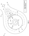
FIG. 2 is a schematic cross-sectional illustration of the aircraft system at an inlet structure with a single airflow inlet. -
FIG. 3 is a plan view illustration of a portion of an inlet guide at an intersection between a fine screen and a coarse screen with enlarged views of the fine screen and the coarse screen. -
FIG. 4 is a schematic cross-sectional illustration of the aircraft system at the inlet structure during icing condition operation. -
FIG. 5 is a schematic cross-sectional illustration of the aircraft system at the inlet structure with multiple airflow inlets. -
FIG. 1 illustrates asystem 20 for an aircraft. This aircraft may be configured as an airplane, a helicopter, a drone (e.g., an unmanned aerial vehicle (UAV)) or any other manned or unmanned aerial vehicle or system. Theaircraft system 20 ofFIG. 1 includes amechanical load 22 and agas turbine engine 24 for powering themechanical load 22. Theaircraft system 20 also includes an (e.g., annular)airflow inlet structure 26 and a circumferentially tailoredinlet guard 28; e.g., an inlet screen assembly with circumferentially non-uniform screen spacing. - The
mechanical load 22 includes at least (or only) onerotor 32 operable to be rotatably driven by thegas turbine engine 24. Thismechanical load 22 may be configured as a propulsor for propelling the aircraft during flight. The drivenrotor 32, for example, may be a bladed propulsor rotor. An example of the propulsor rotor is a propeller rotor where thegas turbine engine 24 is a turboprop gas turbine engine. Another example of the propulsor rotor is a helicopter rotor (e.g., a main rotor) where thegas turbine engine 24 is a turboshaft gas turbine engine. Themechanical load 22, however, may alternatively be configured as an electrical power generator. The drivenrotor 32, for example, may be a generator rotor where thegas turbine engine 24 is an auxiliary power unit (APU). The present disclosure, however, is not limited to the foregoing exemplary driven rotor types nor the foregoing exemplary gas turbine engine types. - The
gas turbine engine 24 ofFIG. 1 extends axially along anaxis 34. Thisaxis 34 may be a centerline axis of thegas turbine engine 24 and/or a rotational axis of one or more rotating assemblies (e.g., 36 and 38) within thegas turbine engine 24. Thegas turbine engine 24 ofFIG. 1 includes acompressor section 40, acombustor section 41 and aturbine section 42. Theturbine section 42 ofFIG. 1 includes a high pressure turbine (HPT)section 42A and a low pressure turbine (LPT)section 42B, whichLPT section 42B may also be referred to as a power turbine (PT) section and/or a free turbine section. - The
compressor section 40 includes abladed compressor rotor 44. TheHPT section 42A includes a bladed high pressure turbine (HPT)rotor 45. TheLPT section 42B includes a bladed low pressure turbine (LPT)rotor 46, whichLPT rotor 46 may also be referred to as a power turbine (PT) rotor and/or a free turbine rotor. Each of these bladed engine rotors 44-46 includes one or more arrays of rotor blades (e.g., airfoils, vanes, etc.), where each rotor blade array is arranged circumferentially around and connected to a respective rotor base; e.g., a disk or a hub. - The
compressor rotor 44 is connected to theHPT rotor 45 through ahigh speed shaft 48. At least (or only) thecompressor rotor 44, theHPT rotor 45 and thehigh speed shaft 48 may collectively form or may otherwise be a part of the highspeed rotating assembly 36; e.g., a high speed spool. TheLPT rotor 46 is connected to alow speed shaft 50. At least (or only) theLPT rotor 46 and thelow speed shaft 50 may collectively form or may otherwise be a part of the lowspeed rotating assembly 38. This lowspeed rotating assembly 38 ofFIG. 1 is coupled to the drivenrotor 32 through a geartrain 52 (e.g., an epicyclic geartrain) and apropulsor shaft 53. However, in other embodiments, the drivenrotor 32 may be part of the lowspeed rotating assembly 38 where, for example, thelow speed shaft 50 connects theLPT rotor 46 to the drivenrotor 32 without thegeartrain 52. - The
inlet structure 26 is configured to direct air into thegas turbine engine 24 from anenvironment 54 external to theaircraft system 20 and, more generally, external to the aircraft. Thisinlet structure 26 may be configured as a standalone structure. Alternatively, theinlet structure 26 may be configured as a part of a housing structure for thegas turbine engine 24 and/or one or more other components of the aircraft. - The
inlet structure 26 ofFIG. 1 includes a (e.g., annular)first wall 56 and a (e.g., annular)second wall 58. Each of theseinlet structure walls gas turbine engine 24. Thefirst wall 56 is spaced axially along theaxis 34 from thesecond wall 58, thereby providing theinlet structure 26 with aninlet plenum 60; e.g., an internal volume such as an annular cavity. Thisinlet plenum 60 extends axially along theaxis 34 within theinlet structure 26 between and to thefirst wall 56 and thesecond wall 58. Theinlet plenum 60 extend radially inward (relative to the axis 34) within theinlet structure 26 to thegas turbine engine 24 and, more particularly, to anairflow inlet 62 into thegas turbine engine 24. Thisengine inlet 62 may be an opening (e.g., an annular orifice) in an outer case of thegas turbine engine 24 that houses thecompressor section 40, thecombustor section 41, theHPT section 42A and theLPT section 42B. - During gas turbine engine operation, (e.g., fresh, ambient) air from the
external environment 54 enters aflowpath 64 of theaircraft system 20 and itsgas turbine engine 24 through anairflow inlet 66 into theinlet structure 26. Thisflowpath 64 extends longitudinally in theaircraft system 20 from thestructure inlet 66 to a combustion products exhaust 68 from thegas turbine engine 24. An upstream portion of theflowpath 64 is formed within and extends longitudinally through theinlet structure 26. Theflowpath 64 ofFIG. 1 , for example, extends radially inward towards theaxis 34 from thestructure inlet 66, through theinlet plenum 60, to theengine inlet 62. A downstream portion of theflowpath 64 is formed within and extends longitudinally through thegas turbine engine 24. Theflowpath 64 ofFIG. 1 , for example, projects radially inward towards theaxis 34 into thegas turbine engine 24 from theengine inlet 62. Theflowpath 64 subsequently extends from theengine inlet 62, sequentially through thecompressor section 40, thecombustor section 41, theHPT section 42A and theLPT section 42B, to theengine exhaust 68. - The
flowpath 64 directs the air longitudinally (e.g., in a radial inward direction towards the axis 34) through theinlet plenum 60 and theengine inlet 62 into thegas turbine engine 24. Within thegas turbine engine 24, the air is compressed by thecompressor rotor 44 and directed into a (e.g., annular)combustion chamber 70 of a (e.g., annular) combustor in thecombustor section 41. Fuel is injected into thecombustion chamber 70 and mixed with the compressed air to provide a fuel-air mixture. This fuel-air mixture is ignited and combustion products thereof flow through and sequentially cause theHPT rotor 45 and theLPT rotor 46 to rotate before being exhausted from thegas turbine engine 24 through theengine exhaust 68 into theexternal environment 54. The rotation of theHPT rotor 45 drives rotation of thecompressor rotor 44 and, thus, compression of the air received through theinlet plenum 60 and theengine inlet 62. The rotation of theLPT rotor 46 drives rotation of the drivenrotor 32. Where the drivenrotor 32 is a propulsor rotor such as the propeller rotor shown inFIG. 1 , the rotation of the drivenrotor 32 propels air outside of thegas turbine engine 24 in an aft direction along theaxis 34 to provide forward aircraft flight. Where the drivenrotor 32 is the generator rotor, the rotation of the drivenrotor 32 drives the electrical power generator to generate electrical power. - Under certain circumstances, the air entering the
flowpath 64 through thestructure inlet 66 may include foreign object debris. For example, during winter aircraft operation, some or all of an ice accumulation on an exterior surface of the aircraft and itsaircraft system 20 may break off and be ingested by theflowpath 64 through thestructure inlet 66. Large pieces of ice may cause damage to the gas turbine engine 24 (e.g., to the blades of thecompressor rotor 44 and/or vanes within the compressor section 40) if allowed to move freely with the incoming air along theflowpath 64 into thegas turbine engine 24 and itscompressor section 40. Other relatively large foreign object debris such as a bird may also cause damage to the gas turbine engine 24 (e.g., to the blades of thecompressor rotor 44 and/or vanes within the compressor section 40) if allowed to move freely with the incoming air along theflowpath 64 into thegas turbine engine 24 and itscompressor section 40. - To prevent or reduce foreign object debris related damage, the
inlet guard 28 is arranged along the flowpath 64 (e.g., anywhere) longitudinally upstream of thecompressor section 40 and itscompressor rotor 44. Theinlet guard 28 ofFIG. 1 , for example, is arranged at (e.g., on, adjacent or proximate) theengine inlet 62. More particularly, theinlet guard 28 ofFIG. 1 is disposed in (or adjacent) theinlet plenum 60 radially outboard of (or inline with) theengine inlet 62. Thisinlet guard 28 extends axially across the flowpath 64 from thefirst wall 56 to thesecond wall 58. Referring toFIG. 2 , theinlet guard 28 also extends circumferentially about (e.g., completely around) theaxis 34. Theinlet guard 28 thereby laterally overlaps (e.g., completely axially and/or circumferentially covers) theengine inlet 62. - The
inlet guard 28 includes and is formed by a plurality of arcuate inlet guard screens. The inlet guard screens ofFIG. 2 include afine screen 72A and acoarse screen 72B. Thefine screen 72A includes a plurality offine perforations 74A (e.g., relatively small through-apertures), where each of thefine perforations 74A projects (e.g., radially) through thefine screen 72A. Thecoarse screen 72B includes a plurality ofcoarse perforations 74B (e.g., relatively large through-apertures), where each of thecoarse perforations 74B projects (e.g., radially) through thecoarse screen 72B. Thescreen perforations flowpath 64 longitudinally upstream of (e.g., radially outboard of) theinlet guard 28 with a portion of theflowpath 64 longitudinally downstream of (e.g., radially inboard of) theinlet guard 28. With this arrangement, theinlet guard 28 ofFIG. 1 filters (e.g., all of) the air flowing longitudinally within theflowpath 64 before entering thecompressor section 40 and, more generally, thegas turbine engine 24. Theinlet guard 28 may thereby block the foreign object debris from moving along theflowpath 64 into thegas turbine engine 24 and itscompressor section 40. - Referring to
FIG. 2 , each of the inlet guard screens 72A, 72B (generally referred to as "72") extends circumferentially about theaxis 34 between and to a circumferentialfirst end inlet guard screen second end inlet guard screen fine screen 72A ofFIG. 2 is arranged circumferentially next to thecoarse screen 72B about theaxis 34. The fine screenfirst end 76A ofFIG. 2 , for example, is disposed next to and may engage (e.g., contact) and/or otherwise be connected to the coarse screensecond end 78B. Similarly, the fine screensecond end 78A ofFIG. 2 is disposed next to and may engage and/or otherwise be connected to the coarse screenfirst end 76B. Thefine screen 72A and thecoarse screen 72B ofFIG. 2 thereby collectively provide theinlet guard 28 with a full-hoop (e.g., tubular) body. - The
fine screen 72A has acircumferential width 80A which extends circumferentially about theaxis 34 between the fine screenfirst end 76A and the fine screensecond end 78A. Thecoarse screen 72B has acircumferential width 80B which extends circumferentially about theaxis 34 between the coarse screenfirst end 76B and the coarse screensecond end 78B. Thiscoarse screen width 80B may be different than (e.g., less than) thefine screen width 80A. Thefine screen width 80A, for example, may extend less than one-hundred and eighty degrees (180°), one-hundred and twenty degrees (120°) or ninety degrees (90°) about theaxis 34. Thecoarse screen width 80B, by contrast, may respectively extend more than one-hundred and eighty degrees (180°), two-hundred and forty degrees (240°) or two-hundred and seventy degrees (270°) about theaxis 34. Thecoarse screen 72B ofFIG. 2 may thereby form a major portion (e.g., more than 50%) of theinlet guard 28. The present disclosure, however, is not limited to such an exemplary relationship between thefine screen 72A and thecoarse screen 72B. Thefine screen width 80A, for example, may be adjusted based on a circumferential width of thestructure inlet 66. - Referring to
FIG. 3 , each of the inlet guard screens 72A, 72B may extend axially along theaxis 34 between and to an axialfirst side 82 of inlet guard screens 72 and an axialsecond side 84 of the inlet guard screens 72. The screenfirst side 82 may also be an axial first side of theinlet guard 28, and the screensecond side 84 may also be an axial second side of theinlet guard 28. Theinlet guard screens axis 34. Thefine screen 72A thereby extends axially along (e.g., axially overlaps) thecoarse screen 72B, and thecoarse screen 72B thereby extends axially along (e.g., axially overlaps) thefine screen 72A. Moreover, thefine screen 72A and thecoarse screen 72B ofFIG. 3 share a common (the same) axial length along theaxis 34. - Each of the
inlet guard screen FIG. 3 includes a plurality ofscreen elements - Some or all of the
fine perforations 74A in thefine screen 72A may be configured with a common geometry; e.g., shape and/or size. Eachfine perforation 74A ofFIG. 3 , for example, is configured with a common polygonal shape; e.g., a rectangular shape. Eachfine perforation 74A ofFIG. 3 is also configured with a common size; e.g.,axial width 90A, circumferential width 92A and/or cross-sectional area. Thefine perforations 74A in thefine screen 72A ofFIG. 3 may thereby have uniform configuration axially and/or circumferentially along (e.g., an entirety of) thefine screen 72A. Similarly, some or all of thecoarse perforations 74B in thecoarse screen 72B may be configured with a common geometry; e.g., shape and/or size. Eachcoarse perforation 74B ofFIG. 3 , for example, is configured with a common polygonal shape; e.g., a rectangular shape. Eachcoarse perforation 74B ofFIG. 3 is also configured with a common size; e.g.,axial width 90B,circumferential width 92B and/or cross-sectional area. Thecoarse perforations 74B in thecoarse screen 72B ofFIG. 3 may thereby have uniform configuration axially and/or circumferentially along (e.g., an entirety of) thecoarse screen 72B. Alternatively, the geometries of thecoarse perforations 74B may vary along a portion or an entirety of thecoarse screen 72B. For example, the shape and/or size of thecoarse perforations 74B may gradually or intermittently change to vary open area axially and/or circumferentially along thecoarse screen 72B. In addition or alternatively, the geometries of thefine perforation 74A may vary along a portion or an entirety of thefine screen 72A. For example, the shape and/or size of thefine perforation 74A may gradually or intermittently change to vary open area axially and/or circumferentially along thefine screen 72A. - While the
fine perforations 74A and thecoarse perforations 74B may (or may not) share a common shape, the size of eachfine perforation 74A is smaller than the size of eachcoarse perforation 74B. The fine perforationaxial width 90A, for example, may be smaller than the coarse perforationaxial width 90B. The fine perforation circumferential width 92A may also or alternatively be smaller than the coarseperforation circumferential width 92B. The fine perforation cross-sectional area may thereby be smaller than the coarse perforation cross-sectional area. By providing thefine perforations 74A with smaller cross-sectional areas than thecoarse perforations 74B, thefine screen 72A may be provided with a smaller percentage of open area (POA) than a percentage of open area of thecoarse screen 72B. The term "percentage of open area" may describe a percentage of a face surface of a screen that is occupied by open area, where the open area is collectively formed by perforations in the screen. Thus, since thefine screen elements fine screen 72A are spaced closer together than thecoarse screen elements coarse screen 72B, more of a face surface of thefine screen 72A is occupied by itsfine screen elements coarse screen 72B is occupied by itscoarse screen elements fine screen 72A may filter out finer debris out of the air flowing within theflowpath 64 than thecoarse screen 72B. As a result, thefine screen 72A is associated with a higher flow resistance thereacross than thecoarse screen 72B. - Referring to
FIG. 2 , thefine screen 72A is circumferentially and axially aligned with thestructure inlet 66. Thestructure inlet 66 ofFIG. 2 , for example, is disposed radially outboard of and circumferentially and/or axially overlaps at least a center portion or the entirety of thefine screen 72A. Thefine screen 72A ofFIG. 2 is thereby located along a direct line-of-sight 94 from thestructure inlet 66 to theengine inlet 62. By contrast, thecoarse screen 72B may be circumferentially offset from thestructure inlet 66. Thestructure inlet 66 ofFIG. 2 , for example, may only circumferentially overlap one or more circumferential end portions of thecoarse screen 72B, or may not circumferentially overlap thecoarse screen 72B at all. Thecoarse screen 72B ofFIG. 2 is thereby located to circumferential peripheral sides of the direct line-of-sight 94 from thestructure inlet 66 to theengine inlet 62. - Referring to
FIG. 4 , the foregoing arrangement may be particularly useful during icing conditions. Ice and/or supercooled water droplets entering theflowpath 64 through thestructure inlet 66, for example, may impinge against and be blocked by thefine screen 72A. Moreover, the impinging incoming air with the water droplets may also tend to causeice 96 to accrete on thefine screen 72A rather than thecoarse screen 72B. Thus, even where airflow across thefine screen 72A is reduced or blocked by ice accretions, the incoming air may continue to flow through the (e.g., substantially) unobstructedcoarse screen 72B. Furthermore, during non-icing conditions, the incoming air is subject to less overall air resistance than if theentire inlet guard 28 was formed by a single screen with a completely uniform perforation size. Theinlet guard 28 and its inlet guard screens 72 may thereby facilitate improved and more stable performance during both icing and non-icing conditions. - In some embodiments, referring to
FIG. 2 , theinlet structure 26 may include asingle structure inlet 66 into theinlet plenum 60. In other embodiments however, referring toFIG. 5 , theinlet structure 26 may include multiple of thestructure inlets 66 into theinlet plenum 60. With such an arrangement, theinlet guard 28 may include multiple of thefine screens 72A such that eachstructure inlet 66 may circumferentially and/or axially overlap a respective one of thefine screens 72A. Theinlet guard 28 ofFIG. 5 also include multiple of thecoarse screens 72B', 72B". Here, thefine screens 72A are circumferentially interspersed with thecoarse screens 72B' and 72B", and thecoarse screens 72B' and 72B" are circumferentially interspersed with thefine screens 72A. In the specific arrangement ofFIG. 5 , thefine screens 72A are configured with a common circumferential width. This fine screen circumferential width may be greater than the circumferential width of the (e.g., top)coarse screen 72B', and may be less than the circumferential width of the (e.g., bottom)coarse screen 72B". The present disclosure, however, is not limited to such an exemplary arrangement nor to such an exemplary dimensional relationships. - The
aircraft system 20 is described above as including thegas turbine engine 24. The present disclosure, however, is not limited to including such an exemplary type of aircraft engine. Theaircraft system 20, for example, may alternatively include a reciprocating piston engine, a rotary engine (e.g., a Wenkel engine) or any other type of aircraft engine which may receive its incoming air through a circumferentially and/or otherwise tailoredinlet guard 28 as generally described above. - While various embodiments of the present disclosure have been described, it will be apparent to those of ordinary skill in the art that many more embodiments and implementations are possible within the scope of the disclosure. For example, the present disclosure as described herein includes several aspects and embodiments that include particular features. Although these features may be described individually, it is within the scope of the present disclosure that some or all of these features may be combined with any one of the aspects and remain within the scope of the disclosure. Accordingly, the present disclosure is not to be restricted except in light of the attached claims and their equivalents.
Claims (15)
- A system (20) for an aircraft, comprising:a gas turbine engine (24) including a compressor section (40);a flowpath (64) projecting longitudinally into the gas turbine engine (24) from an airflow inlet (66) and longitudinally through the compressor section (40); andan inlet guard (28) extending across the flowpath (64) longitudinally upstream of the compressor section (40), the inlet guard (28) extending circumferentially about an axis (34), the inlet guard (28) including a first screen (72A) and a second screen (72B), the first screen (72A) comprising a plurality of first perforations (74A) with a first perforation size, the second screen (72B) circumferentially adjacent the first screen (72A) about the axis (34), and the second screen (72B) comprising a plurality of second perforations (74B) with a second perforation size that is different than the first perforation size.
- The system (20) of claim 1, wherein:the first screen (72A) is circumferentially aligned with the airflow inlet (66) about the axis (34); andthe second screen (72B) is circumferentially offset from the airflow inlet (66) about the axis (34).
- The system (20) of claim 1 or 2, wherein the second perforation (74B) size is greater than the first perforation (74A) size.
- The system (20) of any preceding claim, wherein:the inlet guard (28) further includes a third screen comprising a plurality of third perforations with a third perforation size that is different than the second perforation size; andthe second screen (72B') is arranged circumferentially between the first screen (72A) and the third screen about the axis (34).
- The system (20) of claim 4, wherein:the airflow inlet (66) is a first airflow inlet, and the flowpath (64) further projects longitudinally into the gas turbine engine (24) from a second airflow inlet (66);the first screen (72A) is circumferentially aligned with the first airflow inlet (66) about the axis (34); andthe third screen is circumferentially aligned with the second airflow inlet (66) about the axis (34).
- The system (20) of claim 4 or 5, wherein the third perforation size is equal to the first perforation size.
- The system (20) of any of claims 4 to 6, wherein:the inlet guard (28) further includes a fourth screen (72B") comprising a plurality of fourth perforations with a fourth perforation size that is different than the first perforation size and the second perforation size;the third screen is arranged circumferentially between the second screen (72B) and the fourth screen (72B") about the axis (34); andthe fourth screen (72B") is arranged circumferentially between the first screen (72A) and the third screen about the axis (34).
- The system (20) of claim 7, wherein:the first screen (72A) has a first circumferential width (80A) about the axis (34);the second screen (72B) has a second circumferential width (80B) about the axis (34) that is different than the first circumferential width (80A);the third screen has a third circumferential width about the axis (34) that is equal to the first circumferential width (80A); andthe fourth screen (72B") has a fourth circumferential width about the axis (34) that is different than the first circumferential width (80A), optionally wherein at least one of:the second circumferential width (80B) is smaller than the first circumferential width (80A); orthe fourth circumferential width is greater than the first circumferential width (80A).
- The system (20) of any preceding claim, wherein:the first screen (72A) has a first circumferential width (80A) about the axis (34); andthe second screen (72B) has a second circumferential width (80B) about the axis (34) that is different than the first circumferential width (80A).
- The system (20) of any preceding claim, wherein at least one of:the first screen (72A) extends less than one-hundred and eighty degrees about the axis (34); and/orthe second screen (72B) extends more than one-hundred and eighty degrees about the axis (34), optionally wherein at least one of:the first screen (72A) extends less than one-hundred and twenty degrees about the axis (34); and/orthe second screen (72B) extends more than one-hundred and twenty degrees about the axis (34).
- The system (20) of any preceding claim, wherein:
the inlet guard (28) extends circumferentially about the gas turbine engine (24); and/or
the inlet guard (28) extends axially along the axis (34) and the first screen (72A) axially overlaps the second screen (72B) along the axis (34). - A system (20) for an aircraft, comprising:a gas turbine engine (24) including a compressor section (40);an inlet guard (28) extending circumferentially about and axially along an axis (34), the inlet guard (28) including a first screen (72A) and a second screen (72B), the first screen (72A) comprising a first percentage of open area, the second screen (72B) comprising a second percentage of open area that is different than the first percentage of open area, the second screen (72B) extending circumferentially about the axis (34) to the first screen (72A), and the second screen (72B) extending axially along the first screen (72A); anda flowpath (64) projecting longitudinally from an airflow inlet (66), through the inlet guard (28), to the compressor section (40).
- The system (20) of claim 12, wherein at least one of:the flowpath (64) projects radially through the first screen (72A) and the second screen (72B) into the gas turbine engine (24);the first screen (72A) comprises a plurality of first perforations (74A), and each of the plurality of first perforations (74A) has a first cross-sectional area, the second screen (72B) comprises a plurality of second perforations (74B), and each of the plurality of second perforations (74B) has a second cross-sectional area that is different than the first cross-sectional area; and/orthe airflow inlet (66) extends circumferentially about the axis (34) between opposing circumferential sides and the airflow inlet (66) is radially outboard of and circumferentially overlaps the first screen (72A).
- A system (20) for an aircraft, comprising:an aircraft engine with a flowpath (64) projecting into the aircraft engine from an airflow inlet (66); andan inlet guard (28) arranged at the airflow inlet (66) and extending across the flowpath (64), the inlet guard (28) extending circumferentially about an axis (34), the inlet guard (28) including a first screen (72A) and a second screen (72B), the first screen (72A) comprising a plurality of first perforations (74A) with a first perforation size, the second screen (72B) comprising a plurality of second perforations (74B) with a second perforation size that is different than the first perforation size, and the second screen (72B) arranged circumferentially next to the first screen (72A) about the axis (34).
- The system (20) of claim 14, wherein the aircraft engine comprises a gas turbine engine (24).
Applications Claiming Priority (1)
| Application Number | Priority Date | Filing Date | Title |
|---|---|---|---|
| US18/377,186 US20250115366A1 (en) | 2023-10-05 | 2023-10-05 | Circumferentially tailored inlet guard for an aircraft engine inlet |
Publications (1)
| Publication Number | Publication Date |
|---|---|
| EP4534827A1 true EP4534827A1 (en) | 2025-04-09 |
Family
ID=93015081
Family Applications (1)
| Application Number | Title | Priority Date | Filing Date |
|---|---|---|---|
| EP24205102.7A Pending EP4534827A1 (en) | 2023-10-05 | 2024-10-07 | Circumferentially tailored inlet guard for an aircraft engine inlet |
Country Status (3)
| Country | Link |
|---|---|
| US (1) | US20250115366A1 (en) |
| EP (1) | EP4534827A1 (en) |
| CA (1) | CA3255812A1 (en) |
Citations (3)
| Publication number | Priority date | Publication date | Assignee | Title |
|---|---|---|---|---|
| US2399186A (en) * | 1943-10-14 | 1946-04-30 | Goodrich Co B F | Shield assembly for aircraft |
| US20170268424A1 (en) * | 2016-03-17 | 2017-09-21 | General Electric Company | Internally Heated Engine Inlet Screen for Aircraft Engines |
| US20180245514A1 (en) * | 2017-01-24 | 2018-08-30 | Rolls-Royce Plc | Gas turbine engine arrangement |
Family Cites Families (12)
| Publication number | Priority date | Publication date | Assignee | Title |
|---|---|---|---|---|
| US2730863A (en) * | 1948-04-16 | 1956-01-17 | Lockheed Aircraft Corp | Gaseous fuel turbine power plant having parallel connected compressors |
| US2846023A (en) * | 1956-04-19 | 1958-08-05 | Gen Dynamics Corp | Protective device for jet engines |
| US3319402A (en) * | 1964-12-14 | 1967-05-16 | United Aircraft Canada | Air inlet screen |
| US3329377A (en) * | 1965-10-11 | 1967-07-04 | United Aircraft Canada | Protection for aircraft engines against snow, ice and airborne particles |
| US4644746A (en) * | 1985-12-30 | 1987-02-24 | L. W. Fleckenstein, Inc. | Gas compressor for jet engine |
| US4989807A (en) * | 1988-04-07 | 1991-02-05 | Grumman Aerospace Corporation | S-shaped jet engine inlet diffuser |
| US6824582B2 (en) * | 2002-12-13 | 2004-11-30 | Westar Corporation | Filter system for turbine engine |
| US6959552B2 (en) * | 2004-03-18 | 2005-11-01 | Pratt & Whitney Canada Corp. | Gas turbine inlet flow straightener |
| US7137240B2 (en) * | 2004-08-18 | 2006-11-21 | Hamilton Sundstrand Corporation | Inlet muff anti-icing system for an auxiliary power unit |
| US7625173B2 (en) * | 2006-12-11 | 2009-12-01 | Hamilton Sundstrand Corporation | Inlet plenum for gas turbine engine |
| US10823063B2 (en) * | 2018-02-13 | 2020-11-03 | General Electric Company | Foreign object damage screen assembly for a gas turbine engine |
| US11066996B2 (en) * | 2018-04-27 | 2021-07-20 | Pratt & Whitney Canada Corp. | Gas turbine engine with inertial particle separator |
-
2023
- 2023-10-05 US US18/377,186 patent/US20250115366A1/en active Pending
-
2024
- 2024-10-04 CA CA3255812A patent/CA3255812A1/en active Pending
- 2024-10-07 EP EP24205102.7A patent/EP4534827A1/en active Pending
Patent Citations (3)
| Publication number | Priority date | Publication date | Assignee | Title |
|---|---|---|---|---|
| US2399186A (en) * | 1943-10-14 | 1946-04-30 | Goodrich Co B F | Shield assembly for aircraft |
| US20170268424A1 (en) * | 2016-03-17 | 2017-09-21 | General Electric Company | Internally Heated Engine Inlet Screen for Aircraft Engines |
| US20180245514A1 (en) * | 2017-01-24 | 2018-08-30 | Rolls-Royce Plc | Gas turbine engine arrangement |
Also Published As
| Publication number | Publication date |
|---|---|
| US20250115366A1 (en) | 2025-04-10 |
| CA3255812A1 (en) | 2025-05-23 |
Similar Documents
| Publication | Publication Date | Title |
|---|---|---|
| EP3543516B1 (en) | Electric propulsion motor cooling system and method | |
| EP4610525A2 (en) | Ribbed seal element for aircraft powerplant | |
| EP4484826A1 (en) | Turbine engine support structure with airflow ports | |
| US20250115366A1 (en) | Circumferentially tailored inlet guard for an aircraft engine inlet | |
| EP4534825A1 (en) | Variable inlet guard for an inlet of an aircraft engine | |
| EP3299587B1 (en) | Gas turbine engine airfoil | |
| US11873758B1 (en) | Gas turbine engine component with integral heat exchanger | |
| US12410712B1 (en) | Rotor blade with apertured cooling air deflector | |
| US20260009334A1 (en) | Notched turbine vane baffle | |
| EP4685337A1 (en) | Shroud arrestor for bladed powerplant rotor | |
| US20260092530A1 (en) | Turbine Engine Rotor Blade With Contoured Pocket Surface(S) | |
| EP4667706A2 (en) | Air cooling system for stator vane structure outer platform | |
| US12421863B2 (en) | Turbine engine tip clearance control system with thrust bearing | |
| US12492711B1 (en) | Open rotor with fixed guide vane/stator | |
| EP4667726A1 (en) | Bleeding core air from a turbine engine core flowpath | |
| US12623785B2 (en) | Open rotor propulsion system with exhaust mixer(s) | |
| EP4733566A2 (en) | Thermal management system for open rotor aircraft propulsion system | |
| US12486798B2 (en) | Variable inlet guard screen for an inlet of an aircraft engine | |
| EP4524366A2 (en) | Multi-piece injector nozzle for a turbine engine | |
| EP4621193A1 (en) | Aircraft powerplant with joint shield | |
| EP4678901A2 (en) | Gas turbine engine with integral actuation system | |
| US12397924B2 (en) | Open rotor aircraft propulsion system with bypass flowpath | |
| EP4571073A2 (en) | Ventilation system for aircraft propulsion system | |
| US20260092556A1 (en) | Open rotor propulsion system with forward exhaust outlet(s) | |
| EP4589124A1 (en) | Bolted connection between mounting bracket and aircraft engine case(s) |
Legal Events
| Date | Code | Title | Description |
|---|---|---|---|
| PUAI | Public reference made under article 153(3) epc to a published international application that has entered the european phase |
Free format text: ORIGINAL CODE: 0009012 |
|
| STAA | Information on the status of an ep patent application or granted ep patent |
Free format text: STATUS: THE APPLICATION HAS BEEN PUBLISHED |
|
| AK | Designated contracting states |
Kind code of ref document: A1 Designated state(s): AL AT BE BG CH CY CZ DE DK EE ES FI FR GB GR HR HU IE IS IT LI LT LU LV MC ME MK MT NL NO PL PT RO RS SE SI SK SM TR |
|
| STAA | Information on the status of an ep patent application or granted ep patent |
Free format text: STATUS: REQUEST FOR EXAMINATION WAS MADE |
|
| 17P | Request for examination filed |
Effective date: 20251009 |