EP4534812A1 - Hydrogen engine - Google Patents
Hydrogen engine Download PDFInfo
- Publication number
- EP4534812A1 EP4534812A1 EP23811449.0A EP23811449A EP4534812A1 EP 4534812 A1 EP4534812 A1 EP 4534812A1 EP 23811449 A EP23811449 A EP 23811449A EP 4534812 A1 EP4534812 A1 EP 4534812A1
- Authority
- EP
- European Patent Office
- Prior art keywords
- hydrogen
- intake
- cylinder
- combustion chamber
- piston
- Prior art date
- Legal status (The legal status is an assumption and is not a legal conclusion. Google has not performed a legal analysis and makes no representation as to the accuracy of the status listed.)
- Pending
Links
Images



Classifications
-
- F—MECHANICAL ENGINEERING; LIGHTING; HEATING; WEAPONS; BLASTING
- F02—COMBUSTION ENGINES; HOT-GAS OR COMBUSTION-PRODUCT ENGINE PLANTS
- F02M—SUPPLYING COMBUSTION ENGINES IN GENERAL WITH COMBUSTIBLE MIXTURES OR CONSTITUENTS THEREOF
- F02M21/00—Apparatus for supplying engines with non-liquid fuels, e.g. gaseous fuels stored in liquid form
- F02M21/02—Apparatus for supplying engines with non-liquid fuels, e.g. gaseous fuels stored in liquid form for gaseous fuels
- F02M21/0203—Apparatus for supplying engines with non-liquid fuels, e.g. gaseous fuels stored in liquid form for gaseous fuels characterised by the type of gaseous fuel
- F02M21/0206—Non-hydrocarbon fuels, e.g. hydrogen, ammonia or carbon monoxide
-
- F—MECHANICAL ENGINEERING; LIGHTING; HEATING; WEAPONS; BLASTING
- F01—MACHINES OR ENGINES IN GENERAL; ENGINE PLANTS IN GENERAL; STEAM ENGINES
- F01M—LUBRICATING OF MACHINES OR ENGINES IN GENERAL; LUBRICATING INTERNAL COMBUSTION ENGINES; CRANKCASE VENTILATING
- F01M13/00—Crankcase ventilating or breathing
- F01M13/02—Crankcase ventilating or breathing by means of additional source of positive or negative pressure
- F01M13/028—Crankcase ventilating or breathing by means of additional source of positive or negative pressure of positive pressure
-
- F—MECHANICAL ENGINEERING; LIGHTING; HEATING; WEAPONS; BLASTING
- F02—COMBUSTION ENGINES; HOT-GAS OR COMBUSTION-PRODUCT ENGINE PLANTS
- F02B—INTERNAL-COMBUSTION PISTON ENGINES; COMBUSTION ENGINES IN GENERAL
- F02B25/00—Engines characterised by using fresh charge for scavenging cylinders
- F02B25/02—Engines characterised by using fresh charge for scavenging cylinders using unidirectional scavenging
- F02B25/04—Engines having ports both in cylinder head and in cylinder wall near bottom of piston stroke
-
- F—MECHANICAL ENGINEERING; LIGHTING; HEATING; WEAPONS; BLASTING
- F02—COMBUSTION ENGINES; HOT-GAS OR COMBUSTION-PRODUCT ENGINE PLANTS
- F02B—INTERNAL-COMBUSTION PISTON ENGINES; COMBUSTION ENGINES IN GENERAL
- F02B43/00—Engines characterised by operating on gaseous fuels; Plants including such engines
-
- F—MECHANICAL ENGINEERING; LIGHTING; HEATING; WEAPONS; BLASTING
- F02—COMBUSTION ENGINES; HOT-GAS OR COMBUSTION-PRODUCT ENGINE PLANTS
- F02M—SUPPLYING COMBUSTION ENGINES IN GENERAL WITH COMBUSTIBLE MIXTURES OR CONSTITUENTS THEREOF
- F02M25/00—Engine-pertinent apparatus for adding non-fuel substances or small quantities of secondary fuel to combustion-air, main fuel or fuel-air mixture
- F02M25/06—Engine-pertinent apparatus for adding non-fuel substances or small quantities of secondary fuel to combustion-air, main fuel or fuel-air mixture adding lubricant vapours
-
- F—MECHANICAL ENGINEERING; LIGHTING; HEATING; WEAPONS; BLASTING
- F02—COMBUSTION ENGINES; HOT-GAS OR COMBUSTION-PRODUCT ENGINE PLANTS
- F02M—SUPPLYING COMBUSTION ENGINES IN GENERAL WITH COMBUSTIBLE MIXTURES OR CONSTITUENTS THEREOF
- F02M35/00—Combustion-air cleaners, air intakes, intake silencers, or induction systems specially adapted for, or arranged on, internal-combustion engines
- F02M35/10—Air intakes; Induction systems
- F02M35/10209—Fluid connections to the air intake system; their arrangement of pipes, valves or the like
- F02M35/10222—Exhaust gas recirculation [EGR]; Positive crankcase ventilation [PCV]; Additional air admission, lubricant or fuel vapour admission
-
- F—MECHANICAL ENGINEERING; LIGHTING; HEATING; WEAPONS; BLASTING
- F01—MACHINES OR ENGINES IN GENERAL; ENGINE PLANTS IN GENERAL; STEAM ENGINES
- F01M—LUBRICATING OF MACHINES OR ENGINES IN GENERAL; LUBRICATING INTERNAL COMBUSTION ENGINES; CRANKCASE VENTILATING
- F01M13/00—Crankcase ventilating or breathing
- F01M13/02—Crankcase ventilating or breathing by means of additional source of positive or negative pressure
- F01M13/021—Crankcase ventilating or breathing by means of additional source of positive or negative pressure of negative pressure
- F01M2013/027—Crankcase ventilating or breathing by means of additional source of positive or negative pressure of negative pressure with a turbo charger or compressor
-
- F—MECHANICAL ENGINEERING; LIGHTING; HEATING; WEAPONS; BLASTING
- F02—COMBUSTION ENGINES; HOT-GAS OR COMBUSTION-PRODUCT ENGINE PLANTS
- F02B—INTERNAL-COMBUSTION PISTON ENGINES; COMBUSTION ENGINES IN GENERAL
- F02B75/00—Other engines
- F02B75/02—Engines characterised by their cycles, e.g. six-stroke
- F02B2075/022—Engines characterised by their cycles, e.g. six-stroke having less than six strokes per cycle
- F02B2075/025—Engines characterised by their cycles, e.g. six-stroke having less than six strokes per cycle two
-
- F—MECHANICAL ENGINEERING; LIGHTING; HEATING; WEAPONS; BLASTING
- F02—COMBUSTION ENGINES; HOT-GAS OR COMBUSTION-PRODUCT ENGINE PLANTS
- F02B—INTERNAL-COMBUSTION PISTON ENGINES; COMBUSTION ENGINES IN GENERAL
- F02B75/00—Other engines
- F02B75/02—Engines characterised by their cycles, e.g. six-stroke
- F02B2075/022—Engines characterised by their cycles, e.g. six-stroke having less than six strokes per cycle
- F02B2075/027—Engines characterised by their cycles, e.g. six-stroke having less than six strokes per cycle four
-
- F—MECHANICAL ENGINEERING; LIGHTING; HEATING; WEAPONS; BLASTING
- F02—COMBUSTION ENGINES; HOT-GAS OR COMBUSTION-PRODUCT ENGINE PLANTS
- F02B—INTERNAL-COMBUSTION PISTON ENGINES; COMBUSTION ENGINES IN GENERAL
- F02B33/00—Engines characterised by provision of pumps for charging or scavenging
- F02B33/32—Engines with pumps other than of reciprocating-piston type
- F02B33/34—Engines with pumps other than of reciprocating-piston type with rotary pumps
-
- Y—GENERAL TAGGING OF NEW TECHNOLOGICAL DEVELOPMENTS; GENERAL TAGGING OF CROSS-SECTIONAL TECHNOLOGIES SPANNING OVER SEVERAL SECTIONS OF THE IPC; TECHNICAL SUBJECTS COVERED BY FORMER USPC CROSS-REFERENCE ART COLLECTIONS [XRACs] AND DIGESTS
- Y02—TECHNOLOGIES OR APPLICATIONS FOR MITIGATION OR ADAPTATION AGAINST CLIMATE CHANGE
- Y02T—CLIMATE CHANGE MITIGATION TECHNOLOGIES RELATED TO TRANSPORTATION
- Y02T10/00—Road transport of goods or passengers
- Y02T10/10—Internal combustion engine [ICE] based vehicles
- Y02T10/30—Use of alternative fuels, e.g. biofuels
Definitions
- Patent Literature 1 requires the ventilation fan to be provided externally in order to forcibly discharge the hydrogen-containing gas from inside the crank case to the outside, i.e., the engine requires a complicated structure.
- the intake supercharged by the supercharger is supplied not only to the combustion chamber but also to the crank chamber, whereby it becomes possible to discharge the blow-by gas from the crank chamber with a simple configuration without employing a ventilation fan and so on, i.e., it is possible to decrease engine oil emulsification and component embrittlement inside the crank chamber.
- the hydrogen engine is provided by a hydrogen two-stroke engine.
- the piston includes a piston ring slidable with respect to an inner circumferential surface of the cylinder, the intake port is provided in a side surface of the cylinder, in a range where the piston ring is movable, and the piston ring functions as the switching portion for the intake supercharged by the supercharger to be switched between being supplied to the crank chamber via the intake port and being supplied to the combustion chamber via the intake port.
- the exhaust port is at a position higher than a top dead center of the piston
- the hydrogen engine further includes an exhaust valve provided in the cylinder in order to open and close the exhaust port.
- the hydrogen engine is provided by a hydrogen four-stroke engine, and further includes an intake path communicating between the intake port and the supercharger; a bypass communicating between the intake path and the crank chamber; and a switching valve functioning as the switching portion for the intake supercharged from the supercharger to be switched between being supplied to the crank chamber via the bypass and being supplied at least to the combustion chamber via the intake port.
- the switching valve which functions as the switching portion, to easily switch the intake supercharged by the supercharger between being supplied at least to the combustion chamber via the intake port (at least to the combustion chamber, of the combustion chamber and the crank chamber) and being supplied to the crank chamber via the bypass.
- the spark plug is at a top portion in the combustion chamber. In this case, it is possible to reliably ignite the mixed gas inside the combustion chamber at a desired timing.
- the hydrogen engine according to the present invention does not emit carbon dioxide in its exhaust, so it can contribute carbon neutrality of transportation equipment and be utilized suitably in transportation equipment.
- the hydrogen engine according to the present invention does not emit carbon dioxide in its exhaust, can have improved power and torque even if the engine has a small displacement, and therefore can contribute carbon neutrality and improved output and torque in small mobility equipment, being suitable for use in small mobility equipment.
- a hydrogen engine 10 is a uniflow hydrogen two-stroke engine, and includes a cylinder 12.
- the cylinder 12 has a crank case 14 connected therewith. Inside the cylinder 12, a piston 16 is provided reciprocatably.
- the crank case 14 accommodates a crank shaft 18.
- the piston 16 and the crank shaft 18 are connected with each other by a connecting rod 20.
- the piston 16 includes a piston ring 22 which is slidable with respect to an inner circumferential surface of the cylinder 12.
- the piston ring 22 is provided near an upper end portion of the piston 16.
- the upper end portion of the piston 16 refers to an end portion of the piston 16 closer to a combustion chamber 24.
- an exhaust pipe 36 is attached to the exhaust port 28.
- a front catalyst 38 is provided inside the exhaust pipe 36.
- an exhaust valve 40 is provided in the cylinder 12.
- the exhaust valve 40 is provided by a poppet valve.
- the cylinder 12 In order to directly inject a hydrogen fuel into the combustion chamber 24, the cylinder 12 is provided with a hydrogen injector 44.
- the hydrogen injector 44 functions as a hydrogen supplying portion for supplying the hydrogen fuel into the cylinder 12.
- the hydrogen injector 44 is at a higher position than the top dead center of the piston 16.
- the hydrogen injector 44 is connected with a hydrogen tank 48 via a regulator 46.
- the hydrogen injector 44 directly injects the hydrogen fuel supplied from the hydrogen tank 48, at an injection pressure adjusted by the regulator 46, into the combustion chamber 24.
- crank case 14 In order to discharge a gas from the crank chamber 50 inside the crank case 14, the crank case 14 is provided with a discharge port 52, and the discharge port 52 has a discharge pipe 54 attached thereto. From the discharge pipe 54, a blow-by gas, for example, which is present inside the crank chamber 50 is discharged to the outside.
- the piston 16 descends, and as the piston 16 comes to the bottom dead center as shown in Fig. 2(b) , the exhaust valve 40 opens the exhaust port 28. Then, as indicated by arrows in Fig. 2(b) , the supercharger 30 supercharges the intake from the intake port 26 into the combustion chamber 24 and the combustion chamber 24 is scavenged. In other words, exhaust which contains water vapor is discharged in a uniflow from the combustion chamber 24. This replaces the gas inside the combustion chamber 24, i.e., an intake (air) which contains oxygen is introduced into the combustion chamber 24.
- the spark plug 42 is provided at a position higher than the top dead center in the cylinder 12. Therefore, it is possible to ignite the mixed gas inside the combustion chamber 24 at a desired timing, regardless of the position of the piston 16.
- the hydrogen injector 44 is provided at a position higher than the top dead center of the piston 16. Therefore, it is possible to inject the hydrogen fuel directly into the combustion chamber 24 at a desired timing, regardless of the position of the piston 16.
- an intake port 116 is provided at a top portion of the cylinder 102.
- An exhaust port 118 is provided at a top portion of the cylinder 102 for discharging from the combustion chamber 114.
- a supercharger 120 is provided upstream of the intake port 116.
- the intake port 116 and the supercharger 120 communicate with each other via an air intake pipe 122 which serves as an intake path.
- the supercharger 120 may be provided by a turbocharger or a supercharger.
- a throttle valve 124 is provided inside the air intake pipe 122 for adjusting an amount of supply of the intake.
- the intake is always supercharged by the supercharger 120.
- an intake valve 126 is provided in the cylinder 102.
- the intake valve 126 is provided by a poppet valve.
- the intake valve 126 functions as a switching portion (switching valve) for switching the intake supercharged from the supercharger 120 between being supplied to the crank chamber 142 (which will be described later) via a bypass 144 (which will be described later) and being supplied to the crank chamber 142 via the bypass 144 and also to the combustion chamber 114 via the intake port 116.
- switching valve switching valve
- an exhaust pipe 128 is attached to the exhaust port 118.
- a front catalyst 130 is provided inside the exhaust pipe 128.
- an exhaust valve 132 is provided in the cylinder 102.
- the exhaust valve 132 is provided by a poppet valve.
- a spark plug 134 is provided in the cylinder 102, at a position higher than the top dead center of the piston 106.
- the spark plug 134 is at a top portion in the combustion chamber 114.
- the cylinder 102 In order to directly inject a hydrogen fuel into the combustion chamber 114, the cylinder 102 is provided with a hydrogen injector 136.
- the hydrogen injector 136 functions as a hydrogen supplying portion for supplying the hydrogen fuel into the cylinder 102.
- the hydrogen injector 136 is at a higher position than the top dead center of the piston 106.
- the hydrogen injector 136 is connected with a hydrogen tank 140 via a regulator 138.
- the hydrogen injector 136 directly injects the hydrogen fuel supplied from the hydrogen tank 140, at an injection pressure adjusted by the regulator 138, into the combustion chamber 114.
- the intake valve 126 opens the intake port 116, and as indicated by Arrows, the supercharger 120 supplies an intake into the combustion chamber 114 from the intake port 116.
- the intake port 116 is completely closed by the intake valve 126, whereby the combustion chamber 114 becomes a closed space, and the combustion chamber 114 is loaded with an intake (air) containing oxygen.
- the intake supercharged by the supercharger 120 is no longer supplied to the combustion chamber 114, but supplied only to the crank chamber 142 via the bypass 144.
- the piston 106 begins to ascend toward the top dead center, bringing the combustion chamber 114 under an increasing compression. Then, as the hydrogen injector 136 makes direct injection of the hydrogen fuel into the combustion chamber 114 at a predetermined timing, a mixed, compressed gas of hydrogen and oxygen is formed inside the combustion chamber 114. Further, as shown in Fig. 5(d) , at an approximate time point when the piston 106 reaches the top dead center, the spark plug 134 causes ignition in the combustion chamber 114, leading to a combustion (explosion) inside the combustion chamber 114.
- the intake supercharged by the supercharger 120 is always supplied to the crank chamber 142 via the bypass 144. This causes constant discharge of a blow-by gas inside the crank chamber 142 from the discharge port 146 via the discharge pipe 148 to the outside.
- the intake valve 126 which is normally provided in a hydrogen four-stroke engine, as a switching valve, it is possible to provide a switching valve without having to prepare a separate one.
- the intake valve 126 opens the intake port 116, to introduce the intake supercharged by the supercharger 120 into the combustion chamber 114 via the intake port 116 and into the crank chamber 142 via the bypass 144.
- the intake valve 126 closes the intake port 116, so the intake supercharged by the supercharger 120 is not supplied to the combustion chamber 114 but supplied to the crank chamber 142 via the bypass 144.
- a switching valve functioning as the switching portion, at a branching place of the air intake pipe 122 and the bypass 144.
- the hydrogen engines 10 and 100 according to the present invention may be utilized not only in the small mobility equipment 1 but also in any transportation equipment. Since the hydrogen engines 10 and 100 do not emit carbon dioxide in their exhaust, they can contribute carbon neutrality of transportation equipment and be utilized suitably in transportation equipment.
Landscapes
- Engineering & Computer Science (AREA)
- Mechanical Engineering (AREA)
- General Engineering & Computer Science (AREA)
- Chemical & Material Sciences (AREA)
- Combustion & Propulsion (AREA)
- Chemical Kinetics & Catalysis (AREA)
- General Chemical & Material Sciences (AREA)
- Oil, Petroleum & Natural Gas (AREA)
- Output Control And Ontrol Of Special Type Engine (AREA)
Abstract
Description
- The present invention relates to hydrogen engines, and more specifically to a hydrogen engine used in transportation equipment and so on.
- In a hydrogen engine, when a hydrogen fuel is combusted in a combustion chamber, the combustion leaves water vapor (water) produced by the combustion and unburned hydrogen fuel inside the combustion chamber. An amount of water produced in this process is greater than an amount of water produced by combustion in a gasoline engine. Part of the water vapor and the unburned hydrogen fuel inside the combustion chamber moves between the cylinder and the piston as blow-by gas to the crank chamber, and it is desirable to discharge the blow-by gas from the crank chamber in order to decrease engine oil emulsification and component embrittlement inside the crank chamber.
- As an example which is pertinent to conventional techniques of discharging blow-by gas from the crank chamber,
Patent Literature 1 discloses a four-stroke engine. The four-stroke engine is capable of operating on a fuel which contains hydrogen gas, and includes a crank case formed with a ventilation port, a ventilation flow path providing communication between the ventilation port and the outside of the crank case, and a ventilation fan provided in the ventilation flow path for forced discharge of a hydrogen-containing gas from inside the crank case to the outside. - Patent Literature 1:
JP-A 2021-127704 - The engine disclosed in
Patent Literature 1 requires the ventilation fan to be provided externally in order to forcibly discharge the hydrogen-containing gas from inside the crank case to the outside, i.e., the engine requires a complicated structure. - Therefore, a primary object of the present invention is to provide a hydrogen engine capable of discharging the blow-by-gas from the crank chamber with a simple structure.
- According to an aspect of the present invention, there is provided a hydrogen engine including a cylinder; a piston provided reciprocatably inside the cylinder; an intake port provided in the cylinder in order to supply an intake to a combustion chamber defined by the cylinder and the piston; an exhaust port provided in the cylinder for discharging from the combustion chamber; a hydrogen supplying portion provided in the cylinder in order to supply a hydrogen fuel into the cylinder; a crank case connected with the cylinder; a discharge port provided in the crank case for discharging from a crank chamber inside the crank case; a supercharger provided upstream of the intake port in order to supercharge the intake to the combustion chamber or the crank chamber; and a switching portion for switching the intake supercharged by the supercharger between being supplied to the crank chamber and being supplied at least to the combustion chamber.
- According to the present invention, the intake supercharged by the supercharger is supplied to either the combustion chamber or the crank chamber by the switching portion. In the combustion chamber, a mixed gas is formed, which contains oxygen from the supercharged intake and hydrogen fuel supplied by the hydrogen supplying portion, for use to drive the hydrogen engine. On the other hand, by supplying the supercharged intake to the crank chamber, there is active discharge of the blow-by gas (containing water vapor and unburned hydrogen fuel) in the crank chamber, through the discharge port. As described, the intake supercharged by the supercharger is supplied not only to the combustion chamber but also to the crank chamber, whereby it becomes possible to discharge the blow-by gas from the crank chamber with a simple configuration without employing a ventilation fan and so on, i.e., it is possible to decrease engine oil emulsification and component embrittlement inside the crank chamber.
- Preferably, the hydrogen engine is provided by a hydrogen two-stroke engine. The piston includes a piston ring slidable with respect to an inner circumferential surface of the cylinder, the intake port is provided in a side surface of the cylinder, in a range where the piston ring is movable, and the piston ring functions as the switching portion for the intake supercharged by the supercharger to be switched between being supplied to the crank chamber via the intake port and being supplied to the combustion chamber via the intake port. In this case, in the hydrogen two-stroke engine, it is possible, with a simple sliding action of the piston ring, which functions as the switching portion, on the inner circumferential surface of the cylinder, to easily switch the intake supercharged by the supercharger between being supplied to the combustion chamber via the intake port and being supplied to the crank chamber via the intake port. Specifically, when the piston ring is at a lower position than the intake port which is provided on the side surface of the cylinder, the intake supercharged by the supercharger is supplied to the combustion chamber. On the other hand, when the piston ring is at a higher position than the intake port which is provided on the side surface of the cylinder, the intake supercharged by the supercharger is supplied to the crank chamber.
- Further, preferably, the exhaust port is at a position higher than a top dead center of the piston, and the hydrogen engine further includes an exhaust valve provided in the cylinder in order to open and close the exhaust port. In this case, it is possible, by operating the exhaust valve thereby opening and closing the exhaust port, to discharge the exhaust from the combustion chamber via the exhaust port at a desired timing, regardless of the position of the piston.
- Further, preferably, the hydrogen engine is provided by a hydrogen four-stroke engine, and further includes an intake path communicating between the intake port and the supercharger; a bypass communicating between the intake path and the crank chamber; and a switching valve functioning as the switching portion for the intake supercharged from the supercharger to be switched between being supplied to the crank chamber via the bypass and being supplied at least to the combustion chamber via the intake port. In this case, in the hydrogen four-stroke engine, it is possible, with the switching valve which functions as the switching portion, to easily switch the intake supercharged by the supercharger between being supplied at least to the combustion chamber via the intake port (at least to the combustion chamber, of the combustion chamber and the crank chamber) and being supplied to the crank chamber via the bypass.
- Preferably, the switching valve includes an intake valve provided in the cylinder in order to open and close the intake port. In this case, by using the intake valve, which is normally provided in a hydrogen four-stroke engine, as a switching valve, it is possible to provide a switching valve without having to prepare a separate one. Typically, while the piston descends from the top dead center toward the bottom dead center, the intake valve opens the intake port, to introduce the intake supercharged by the supercharger into the combustion chamber via the intake port and into the crank chamber via the bypass. During the other time, on the other hand, the intake valve closes the intake port, so the intake supercharged by the supercharger is not supplied to the combustion chamber but supplied to the crank chamber via the bypass.
- Further, preferably, the hydrogen engine further includes a spark plug provided in the cylinder, at a position higher than the top dead center in order to ignite the combustion chamber. In this case, it is possible to ignite the mixed gas inside the combustion chamber at a desired timing, regardless of the position of the piston.
- Further, preferably, the spark plug is at a top portion in the combustion chamber. In this case, it is possible to reliably ignite the mixed gas inside the combustion chamber at a desired timing.
- Preferably, the hydrogen supplying portion includes a hydrogen injector provided at a position higher than a top dead center of the piston in order to inject the hydrogen fuel directly into the combustion chamber. In this case, it is possible to inject the hydrogen fuel directly into the combustion chamber at a desired timing, regardless of the position of the piston.
- The hydrogen engine according to the present invention does not emit carbon dioxide in its exhaust, so it can contribute carbon neutrality of transportation equipment and be utilized suitably in transportation equipment.
- The hydrogen engine according to the present invention does not emit carbon dioxide in its exhaust, can have improved power and torque even if the engine has a small displacement, and therefore can contribute carbon neutrality and improved output and torque in small mobility equipment, being suitable for use in small mobility equipment.
- According to the present invention, there is provided a hydrogen engine capable of discharging exhaust from the crank chamber with a simple structure.
-
-
Fig. 1 is a schematic diagram which shows a hydrogen engine according to an embodiment of the present invention. -
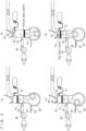
Fig. 2 is an illustrative drawing for describing an operation of the hydrogen engine inFig. 1 . -
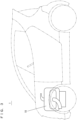
Fig. 3 is a schematic diagram which shows small mobility equipment equipped with the hydrogen engine inFig. 1 . -
Fig. 4 is a schematic diagram which shows a hydrogen engine according to another embodiment of the present invention. -
Fig. 5 is an illustrative drawing for describing an operation of the hydrogen engine inFig. 4 . -
Fig. 6 is an illustrative drawing which shows actions following those shown inFig. 5 . - Hereinafter, embodiments of the present invention will be described with reference to the drawings.
- Referring to
Fig. 1 , ahydrogen engine 10 according to an embodiment of the present invention is a uniflow hydrogen two-stroke engine, and includes acylinder 12. Thecylinder 12 has acrank case 14 connected therewith. Inside thecylinder 12, apiston 16 is provided reciprocatably. Thecrank case 14 accommodates acrank shaft 18. Thepiston 16 and thecrank shaft 18 are connected with each other by a connectingrod 20. Thepiston 16 includes apiston ring 22 which is slidable with respect to an inner circumferential surface of thecylinder 12. Thepiston ring 22 is provided near an upper end portion of thepiston 16. The upper end portion of thepiston 16 refers to an end portion of thepiston 16 closer to acombustion chamber 24. Thepiston ring 22 functions as a switching portion for switching an intake supercharged by a supercharger 30 (which will be described later) between going through an intake port 26 (which will be described later) to be supplied to a crank chamber 50 (which will be described later) and going through theintake port 26 to be supplied to thecombustion chamber 24. - In order to supply an intake to the
combustion chamber 24 which is defined by thecylinder 12 and thepiston 16, anintake port 26 is provided on a side surface of thecylinder 12. Anexhaust port 28 is provided in thecylinder 12, at a position higher than theintake port 26 for discharging from thecombustion chamber 24. - The
intake port 26 is located at a position higher than a bottom dead center of thepiston 16 but lower than a top dead center thereof (seeFig. 2(b) and Fig. 2(d) ). In other words, theintake port 26 is provided between the top dead center and the bottom dead center of thepiston 16, i.e., in a range where an upper end portion of thepiston 16 is movable. Also, theintake port 26 is provided in a range where thepiston ring 22 is movable. Therefore, when thepiston 16 is at the bottom dead center, theintake port 26 is at a higher position than the upper end portion of thepiston 16, while it is at a lower position than the upper end portion of thepiston 16 when thepiston 16 is at the top dead center. Also, theexhaust port 28 is at a higher position than the top dead center of thepiston 16. - In order to supercharge an intake from the
intake port 26 to thecombustion chamber 24 or to the crankchamber 50, asupercharger 30 is provided upstream of theintake port 26. Theintake port 26 and thesupercharger 30 communicate with each other via anair intake pipe 32 which serves as an intake path. Thesupercharger 30 may be provided by a turbocharger or a supercharger. Inside theair intake pipe 32, athrottle valve 34 is provided for adjusting an amount of supply of the intake. In the present embodiment, the intake is always supercharged by thesupercharger 30. - In order to discharge exhaust from the
combustion chamber 24, anexhaust pipe 36 is attached to theexhaust port 28. In order to purify the exhaust, afront catalyst 38 is provided inside theexhaust pipe 36. In order to open and close theexhaust port 28, anexhaust valve 40 is provided in thecylinder 12. In the present embodiment, theexhaust valve 40 is provided by a poppet valve. - In order to ignite the
combustion chamber 24, aspark plug 42 is provided in thecylinder 12, at a position higher than the top dead center of thepiston 16. Thespark plug 42 is at a top portion in thecombustion chamber 24. - In order to directly inject a hydrogen fuel into the
combustion chamber 24, thecylinder 12 is provided with ahydrogen injector 44. Thehydrogen injector 44 functions as a hydrogen supplying portion for supplying the hydrogen fuel into thecylinder 12. Thehydrogen injector 44 is at a higher position than the top dead center of thepiston 16. Thehydrogen injector 44 is connected with ahydrogen tank 48 via aregulator 46. Thehydrogen injector 44 directly injects the hydrogen fuel supplied from thehydrogen tank 48, at an injection pressure adjusted by theregulator 46, into thecombustion chamber 24. - In order to discharge a gas from the
crank chamber 50 inside thecrank case 14, thecrank case 14 is provided with adischarge port 52, and thedischarge port 52 has adischarge pipe 54 attached thereto. From thedischarge pipe 54, a blow-by gas, for example, which is present inside thecrank chamber 50 is discharged to the outside. - The
hydrogen engine 10 described thus far operates as follows for example. - First, as shown in
Fig. 2(a) , thepiston 16 descends, and as thepiston 16 comes to the bottom dead center as shown inFig. 2(b) , theexhaust valve 40 opens theexhaust port 28. Then, as indicated by arrows inFig. 2(b) , thesupercharger 30 supercharges the intake from theintake port 26 into thecombustion chamber 24 and thecombustion chamber 24 is scavenged. In other words, exhaust which contains water vapor is discharged in a uniflow from thecombustion chamber 24. This replaces the gas inside thecombustion chamber 24, i.e., an intake (air) which contains oxygen is introduced into thecombustion chamber 24. - Thereafter, as the
piston 16 ascends, theexhaust valve 40 begins to close theexhaust port 28. As shown inFig. 2(c) , when thepiston ring 22 comes to a position higher than theintake port 26 where thecombustion chamber 24 is no longer supplied with the intake, theexhaust port 28 is completely closed by theexhaust valve 40, whereby thecombustion chamber 24 becomes a closed space. Upon this time, thepiston ring 22 switches the destination of the supercharged intake, i.e., the intake supercharged by thesupercharger 30 is supplied to the crankchamber 50. This causes a blow-by gas inside thecrank chamber 50 to be discharged from thedischarge port 52 via thedischarge pipe 54 to the outside. - Under the circumstances described above, the
piston 16 continues to ascend toward the top dead center, bringing thecombustion chamber 24 under an increasing compression. Then, as thehydrogen injector 44 makes direct injection of the hydrogen fuel into thecombustion chamber 24 at a predetermined timing, a mixed, compressed gas of hydrogen and oxygen is formed inside thecombustion chamber 24. Further, as shown inFig. 2(d) , at an approximate time point when thepiston 16 reaches the top dead center, thespark plug 42 causes ignition in thecombustion chamber 24, leading to a combustion (explosion) inside thecombustion chamber 24. - Then, the
piston 16 is pushed downward (toward the bottom dead center), bringing thehydrogen engine 10 to the state shown inFig. 2(a) . The supply of the intake to the crankchamber 50 continues until thepiston ring 22 descends and has passed theintake port 26. Thereafter, intake supply is switched to thecombustion chamber 24. - Thereafter, the above-described cycle of actions is repeated. As described, in the
hydrogen engine 10, a cycle of intake, compression, combustion and exhaust is completed while thepiston 16 makes one complete reciprocating travel. Thehydrogen engine 10 is suitably utilized insmall mobility equipment 1 as shown inFig. 3 . - According to the
hydrogen engine 10 described thus far, the intake supercharged by thesupercharger 30 is supplied to either thecombustion chamber 24 or thecrank chamber 50 by the switching portion. In thecombustion chamber 24, a mixed gas is formed, which contains oxygen from the supercharged intake and hydrogen fuel supplied by thehydrogen injector 44, for use to drive thehydrogen engine 10. On the other hand, by supplying the supercharged intake to the crankchamber 50, there is active discharge of the blow-by gas (containing water vapor and unburned hydrogen fuel) in thecrank chamber 50, through thedischarge port 52. As described, the intake supercharged by thesupercharger 30 is supplied not only to thecombustion chamber 24 but also to the crankchamber 50, whereby it becomes possible to discharge the blow-by gas from thecrank chamber 50 with a simple configuration without employing a ventilation fan and so on, i.e., it is possible to decrease engine oil emulsification and component embrittlement inside thecrank chamber 50. - The
spark plug 42 is provided at a position higher than the top dead center in thecylinder 12. Therefore, it is possible to ignite the mixed gas inside thecombustion chamber 24 at a desired timing, regardless of the position of thepiston 16. - The
spark plug 42 is at a top portion in thecombustion chamber 24. Therefore, it is possible to reliably ignite the mixed gas inside thecombustion chamber 24 at a desired timing. - The
hydrogen injector 44 is provided at a position higher than the top dead center of thepiston 16. Therefore, it is possible to inject the hydrogen fuel directly into thecombustion chamber 24 at a desired timing, regardless of the position of thepiston 16. - The
hydrogen engine 10 does not emit carbon dioxide in its exhaust, can have improved power and torque even if the engine has a small displacement, and therefore can contribute carbon neutrality and improved output and torque in thesmall mobility equipment 1, being suitable for use in thesmall mobility equipment 1. - The above-described functions and advantages are also offered by a
hydrogen engine 100 which will be described later. - Also, according to the
hydrogen engine 10, it is possible, with a simple sliding action of thepiston ring 22 which functions as the switching portion, on the inner circumferential surface of thecylinder 12, to easily switch the intake supercharged by thesupercharger 30 between being supplied to thecombustion chamber 24 via theintake port 26 and being supplied to the crankchamber 50 via theintake port 26. Specifically, when thepiston ring 22 is at a lower position than theintake port 26 which is provided on the side surface of thecylinder 12, the intake supercharged by thesupercharger 30 is supplied to thecombustion chamber 24. On the other hand, when thepiston ring 22 is at a higher position than theintake port 26 which is provided on the side surface of thecylinder 12, the intake supercharged by thesupercharger 30 is supplied to the crankchamber 50. - The
exhaust port 28 is at a position higher than the top dead center of thepiston 16. Therefore, it is possible, by operating theexhaust valve 40 thereby opening and closing theexhaust port 28, to discharge the exhaust from thecombustion chamber 24 via theexhaust port 28 at a desired timing, regardless of the position of thepiston 16. - Next, description will be made for a
hydrogen engine 100, which is another embodiment of the present invention. - Referring to
Fig. 4 , thehydrogen engine 100 is a hydrogen four-stroke engine, and includes acylinder 102. Thecylinder 102 has acrank case 104 connected therewith. Inside thecylinder 102, apiston 106 is provided reciprocatably. The crankcase 104 accommodates acrank shaft 108. Thepiston 106 and thecrank shaft 108 are connected with each other by a connectingrod 110. Thepiston 106 includes apiston ring 112 which is slidable with respect to an inner circumferential surface of thecylinder 102. Thepiston ring 112 is provided near an upper end portion of thepiston 106. The upper end portion of thepiston 106 refers to an end portion of thepiston 106 closer to acombustion chamber 114. - In order to supply an intake to the
combustion chamber 114 which is defined by thecylinder 102 and thepiston 106, anintake port 116 is provided at a top portion of thecylinder 102. Anexhaust port 118 is provided at a top portion of thecylinder 102 for discharging from thecombustion chamber 114. - In order to supercharge an intake from the
intake port 116 to thecombustion chamber 114 or to a crankchamber 142, asupercharger 120 is provided upstream of theintake port 116. Theintake port 116 and thesupercharger 120 communicate with each other via anair intake pipe 122 which serves as an intake path. Thesupercharger 120 may be provided by a turbocharger or a supercharger. Inside theair intake pipe 122, athrottle valve 124 is provided for adjusting an amount of supply of the intake. In the present embodiment, the intake is always supercharged by thesupercharger 120. In order to open and close theintake port 116, anintake valve 126 is provided in thecylinder 102. In the present embodiment, theintake valve 126 is provided by a poppet valve. Theintake valve 126 functions as a switching portion (switching valve) for switching the intake supercharged from thesupercharger 120 between being supplied to the crank chamber 142 (which will be described later) via a bypass 144 (which will be described later) and being supplied to the crankchamber 142 via thebypass 144 and also to thecombustion chamber 114 via theintake port 116. - In order to discharge exhaust from the
combustion chamber 114, anexhaust pipe 128 is attached to theexhaust port 118. In order to purify the exhaust, afront catalyst 130 is provided inside theexhaust pipe 128. In order to open and close theexhaust port 118, anexhaust valve 132 is provided in thecylinder 102. In the present embodiment, theexhaust valve 132 is provided by a poppet valve. - In order to ignite the
combustion chamber 114, aspark plug 134 is provided in thecylinder 102, at a position higher than the top dead center of thepiston 106. Thespark plug 134 is at a top portion in thecombustion chamber 114. - In order to directly inject a hydrogen fuel into the
combustion chamber 114, thecylinder 102 is provided with ahydrogen injector 136. Thehydrogen injector 136 functions as a hydrogen supplying portion for supplying the hydrogen fuel into thecylinder 102. Thehydrogen injector 136 is at a higher position than the top dead center of thepiston 106. Thehydrogen injector 136 is connected with ahydrogen tank 140 via aregulator 138. Thehydrogen injector 136 directly injects the hydrogen fuel supplied from thehydrogen tank 140, at an injection pressure adjusted by theregulator 138, into thecombustion chamber 114. - The
air intake pipe 122 and thecrank chamber 142 inside the crankcase 104 communicate with each other via abypass 144. In order to discharge a gas from thecrank chamber 142 inside the crankcase 104, the crankcase 104 is provided with adischarge port 146, and thedischarge port 146 has adischarge pipe 148 attached thereto. From thedischarge pipe 148, a blow-by gas, for example, which is present inside thecrank chamber 142 is discharged to the outside. - The
hydrogen engine 100 described thus far operates as follows for example. - First, as shown in
Fig. 5(a) , while thepiston 106 moves from its top dead center toward its bottom dead center, theintake valve 126 opens theintake port 116, and as indicated by Arrows, thesupercharger 120 supplies an intake into thecombustion chamber 114 from theintake port 116. As shown inFig. 5(b) , at a point where thepiston 106 is at the bottom dead center, theintake port 116 is completely closed by theintake valve 126, whereby thecombustion chamber 114 becomes a closed space, and thecombustion chamber 114 is loaded with an intake (air) containing oxygen. As described, by closing theintake valve 126, the intake supercharged by thesupercharger 120 is no longer supplied to thecombustion chamber 114, but supplied only to the crankchamber 142 via thebypass 144. - Under the circumstances described above, as shown in
Fig. 5(c) , thepiston 106 begins to ascend toward the top dead center, bringing thecombustion chamber 114 under an increasing compression. Then, as thehydrogen injector 136 makes direct injection of the hydrogen fuel into thecombustion chamber 114 at a predetermined timing, a mixed, compressed gas of hydrogen and oxygen is formed inside thecombustion chamber 114. Further, as shown inFig. 5(d) , at an approximate time point when thepiston 106 reaches the top dead center, thespark plug 134 causes ignition in thecombustion chamber 114, leading to a combustion (explosion) inside thecombustion chamber 114. - Then, the
piston 106 is pushed downward (toward the bottom dead center), assumes the state shown inFig. 6(a) and then comes to the bottom dead center as shown inFig. 6(b) . - Thereafter, as shown in
Fig. 6(c) , while thepiston 106 moves from the bottom dead center toward the top dead center, theexhaust valve 132 opens theexhaust port 118, and as indicated by Arrows, exhaust containing water vapor is discharged from thecombustion chamber 114. - As shown in
Fig. 6(d) , at a point where thepiston 106 is at the top dead center, theexhaust port 118 is completely closed by theexhaust valve 132, and thereafter the cycle returns to the state shown inFig. 5(a) . - In the present embodiment, the intake supercharged by the
supercharger 120 is always supplied to the crankchamber 142 via thebypass 144. This causes constant discharge of a blow-by gas inside thecrank chamber 142 from thedischarge port 146 via thedischarge pipe 148 to the outside. - Thereafter, the above-described cycle of actions is repeated. As described, in the
hydrogen engine 100, a cycle of intake, compression, combustion and exhaust is completed while thepiston 106 makes two complete reciprocating travels. Thehydrogen engine 100 is also suitably utilized in thesmall mobility equipment 1 as shown inFig. 3 . - According to the
hydrogen engine 100 described thus far, by using theintake valve 126, which is normally provided in a hydrogen four-stroke engine, as a switching valve, it is possible to provide a switching valve without having to prepare a separate one. Typically, while thepiston 106 descends from the top dead center toward the bottom dead center, theintake valve 126 opens theintake port 116, to introduce the intake supercharged by thesupercharger 120 into thecombustion chamber 114 via theintake port 116 and into thecrank chamber 142 via thebypass 144. During the other time, on the other hand, theintake valve 126 closes theintake port 116, so the intake supercharged by thesupercharger 120 is not supplied to thecombustion chamber 114 but supplied to the crankchamber 142 via thebypass 144. - It should be noted here that in the
hydrogen engine 100, there may be provided a switching valve functioning as the switching portion, at a branching place of theair intake pipe 122 and thebypass 144. By using this switching valve, it is possible to easily switch the intake supercharged from thesupercharger 120 between being supplied to the crankchamber 142 via thebypass 144 and being supplied to thecombustion chamber 114 via theintake port 116. - The
hydrogen engines small mobility equipment 1 but also in any transportation equipment. Since thehydrogen engines - The present invention being thus far described in terms of preferred embodiments, it is obvious that these may be varied in many ways within the scope and the spirit of the present invention. The scope of the present invention is only limited by the accompanied claims.
-
- 1
- Small mobility equipment
- 10, 100
- Hydrogen engine
- 12, 102
- Cylinder
- 14, 104
- Crank case
- 16, 106
- Piston
- 18, 108
- Crank shaft
- 20, 110
- Connecting rod
- 22, 112
- Piston ring
- 24, 114
- Combustion chamber
- 26, 116
- Intake port
- 28, 118
- Exhaust port
- 30, 120
- Supercharger
- 32, 122
- Air intake pipe
- 36, 128
- Exhaust pipe
- 40, 132
- Exhaust valve
- 42, 134
- Spark plug
- 44, 136
- Hydrogen injector
- 50, 142
- Crank chamber
- 52, 146
- Discharge port
- 54, 148
- Discharge pipe
- 126
- Intake valve
- 144
- Bypass
Claims (10)
- A hydrogen engine comprising: a cylinder;a piston provided reciprocatably inside the cylinder;an intake port provided in the cylinder in order to supply an intake to a combustion chamber defined by the cylinder and the piston;an exhaust port provided in the cylinder for discharging from the combustion chamber;a hydrogen supplying portion provided in the cylinder in order to supply a hydrogen fuel into the cylinder;a crank case connected with the cylinder;a discharge port provided in the crank case for discharging from a crank chamber inside the crank case;a supercharger provided upstream of the intake port in order to supercharge the intake to the combustion chamber or the crank chamber; anda switching portion for switching the intake supercharged by the supercharger between being supplied to the crank chamber and being supplied at least to the combustion chamber.
- The hydrogen engine according to Claim 1, provided by a hydrogen two-stroke engine, whereinthe piston includes a piston ring slidable with respect to an inner circumferential surface of the cylinder,the intake port is provided in a side surface of the cylinder, in a range where the piston ring is movable, andthe piston ring functions as the switching portion for the intake supercharged by the supercharger to be switched between being supplied to the crank chamber via the intake port and being supplied to the combustion chamber via the intake port.
- The hydrogen engine according to Claim 1 or 2, wherein the exhaust port is at a position higher than a top dead center of the piston, and
the hydrogen engine further comprises an exhaust valve provided in the cylinder in order to open and close the exhaust port. - The hydrogen engine according to Claim 1, provided by a hydrogen four-stroke engine, further comprising:an intake path communicating between the intake port and the supercharger;a bypass communicating between the intake path and the crank chamber; anda switching valve functioning as the switching portion for the intake supercharged from the supercharger to be switched between being supplied to the crank chamber via the bypass and being supplied at least to the combustion chamber via the intake port.
- The hydrogen engine according to Claim 4, wherein the switching valve includes an intake valve provided in the cylinder in order to open and close the intake port.
- The hydrogen engine according to one of Claims 1 to 5, further comprising a spark plug provided in the cylinder, at a position higher than the top dead center in order to ignite the combustion chamber.
- The hydrogen engine according to Claim 6, wherein the spark plug is at a top portion in the combustion chamber.
- The hydrogen engine according to one of Claims 1 to 7, wherein the hydrogen supplying portion includes a hydrogen injector provided at a position higher than a top dead center of the piston in order to inject the hydrogen fuel directly into the combustion chamber.
- The hydrogen engine according to one of Claims 1 to 8, for use in transportation equipment.
- The hydrogen engine according to Claim 9, wherein the transportation equipment includes small mobility equipment.
Applications Claiming Priority (2)
| Application Number | Priority Date | Filing Date | Title |
|---|---|---|---|
| JP2022084447 | 2022-05-24 | ||
| PCT/JP2023/013326 WO2023228570A1 (en) | 2022-05-24 | 2023-03-30 | Hydrogen engine |
Publications (2)
| Publication Number | Publication Date |
|---|---|
| EP4534812A1 true EP4534812A1 (en) | 2025-04-09 |
| EP4534812A4 EP4534812A4 (en) | 2025-09-10 |
Family
ID=88919011
Family Applications (1)
| Application Number | Title | Priority Date | Filing Date |
|---|---|---|---|
| EP23811449.0A Pending EP4534812A4 (en) | 2022-05-24 | 2023-03-30 | HYDROGEN ENGINE |
Country Status (3)
| Country | Link |
|---|---|
| EP (1) | EP4534812A4 (en) |
| JP (1) | JP7804069B2 (en) |
| WO (1) | WO2023228570A1 (en) |
Families Citing this family (4)
| Publication number | Priority date | Publication date | Assignee | Title |
|---|---|---|---|---|
| JP2024117362A (en) * | 2023-02-17 | 2024-08-29 | 株式会社小松製作所 | System and method for controlling the same |
| JP2024117361A (en) * | 2023-02-17 | 2024-08-29 | 株式会社小松製作所 | System and method for controlling the same |
| CN117722289B (en) * | 2023-12-15 | 2025-09-02 | 一汽解放汽车有限公司 | Double tumble inlet cylinder head and hydrogen engine |
| WO2025225215A1 (en) * | 2024-04-22 | 2025-10-30 | 株式会社Ihi | Shaft for turbocharger, and turbocharger |
Family Cites Families (16)
| Publication number | Priority date | Publication date | Assignee | Title |
|---|---|---|---|---|
| US6338328B1 (en) * | 2000-12-05 | 2002-01-15 | Louis W. Mower | Crankcase inducted self-supercharging four cycle internal combustion engine |
| KR200431488Y1 (en) * | 2003-04-21 | 2006-11-23 | 미츠비시 쥬고교 가부시키가이샤 | Internal combustion engines with small engine control valve devices |
| JP2007132250A (en) * | 2005-11-09 | 2007-05-31 | Denso Corp | Fuel injection device for internal combustion engine |
| JP2009293464A (en) * | 2008-06-04 | 2009-12-17 | Aisan Ind Co Ltd | Blow-by gas recirculating device for engine with supercharger |
| US8408190B2 (en) * | 2011-07-06 | 2013-04-02 | GM Global Technology Operations LLC | Air-oil separator for extracting oil from engine blowby gas |
| WO2015073380A1 (en) * | 2013-11-12 | 2015-05-21 | Matthew Riley | Systems and methods of forced air induction in internal combustion engines |
| US10138772B2 (en) * | 2014-02-03 | 2018-11-27 | Ford Global Technologies, Llc | System and method for reducing friction |
| JP6582863B2 (en) * | 2015-10-20 | 2019-10-02 | アイシン精機株式会社 | Intake system of an internal combustion engine with a supercharger |
| JP6327272B2 (en) * | 2016-03-15 | 2018-05-23 | マツダ株式会社 | Control device for gas fuel direct injection engine |
| CN106337730B (en) * | 2016-09-07 | 2018-09-28 | 石家庄新华能源环保科技股份有限公司 | A kind of hydrogen-fuel engine system |
| US10570829B2 (en) * | 2017-08-11 | 2020-02-25 | Ford Global Technologies, Llc | Methods and system for a common aspirator valve |
| CN108443010B (en) * | 2018-02-13 | 2021-04-23 | 上海柯来浦能源科技有限公司 | Oxygen direct injection pure hydrogen combustion engine and power system thereof |
| US10876445B2 (en) * | 2019-02-01 | 2020-12-29 | Caterpillar Inc. | Heated inlet of a crankcase ventilation system |
| JP2021127704A (en) | 2020-02-12 | 2021-09-02 | 川崎重工業株式会社 | Four-stroke engine and method for preventing ignition inside crankcase |
| KR20230067525A (en) * | 2021-11-09 | 2023-05-16 | 얀마 홀딩스 주식회사 | Engine system |
| DE102022121952A1 (en) * | 2022-08-31 | 2024-02-29 | Hengst Se | Ventilation system for a crankcase |
-
2023
- 2023-03-30 JP JP2024522951A patent/JP7804069B2/en active Active
- 2023-03-30 EP EP23811449.0A patent/EP4534812A4/en active Pending
- 2023-03-30 WO PCT/JP2023/013326 patent/WO2023228570A1/en not_active Ceased
Also Published As
| Publication number | Publication date |
|---|---|
| JP7804069B2 (en) | 2026-01-21 |
| EP4534812A4 (en) | 2025-09-10 |
| WO2023228570A1 (en) | 2023-11-30 |
| JPWO2023228570A1 (en) | 2023-11-30 |
Similar Documents
| Publication | Publication Date | Title |
|---|---|---|
| US4248185A (en) | Two-cycle engine with pure air scavenging | |
| US8770159B2 (en) | Stratified scavenging two-stroke engine | |
| JP7804069B2 (en) | hydrogen engine | |
| CA2020457A1 (en) | Dual fuel natural gas/diesel 2-stroke engine | |
| US4276858A (en) | Two-cycle internal combustion engine | |
| US5586523A (en) | Crankcase compression type two-cycle engine | |
| US4993372A (en) | Two stroke internal combustion engine with decompression valve | |
| US5775274A (en) | Two-stroke engine with air-blast fuel mixture injection | |
| EP0339969B1 (en) | Two-stroke otto cycle engines | |
| EP4534818A1 (en) | Two-stroke hydrogen engine | |
| JP5608175B2 (en) | Internal combustion engine with independent gas supply system without compression stroke | |
| US7270110B2 (en) | Four stroke internal combustion engine with inlet air compression chamber | |
| EP0349149A2 (en) | Two-stroke engines | |
| US6591793B2 (en) | Two-cycle engine | |
| US7198011B2 (en) | Internal combustion engine | |
| US20040187813A1 (en) | Two-stroke engine | |
| US20190170055A1 (en) | Two-stroke engine with improved performance | |
| US4404938A (en) | Four-stroke-cycle internal combustion engine with fuel injection | |
| US3967611A (en) | Stratified-combustion type internal combustion engine with pre-combustion-chamber | |
| WO2013050068A1 (en) | Two-cycle trunk-piston engine | |
| US11225904B2 (en) | Internal-combustion engine and drive system | |
| FI128955B (en) | A two-stroke engine | |
| US20120006308A1 (en) | Piston for a Two-Stroke Engine | |
| JPS59158328A (en) | Internal-combustion engine | |
| JPH06108864A (en) | Supercharging four-cycle engine |
Legal Events
| Date | Code | Title | Description |
|---|---|---|---|
| STAA | Information on the status of an ep patent application or granted ep patent |
Free format text: STATUS: THE INTERNATIONAL PUBLICATION HAS BEEN MADE |
|
| PUAI | Public reference made under article 153(3) epc to a published international application that has entered the european phase |
Free format text: ORIGINAL CODE: 0009012 |
|
| STAA | Information on the status of an ep patent application or granted ep patent |
Free format text: STATUS: REQUEST FOR EXAMINATION WAS MADE |
|
| 17P | Request for examination filed |
Effective date: 20241205 |
|
| AK | Designated contracting states |
Kind code of ref document: A1 Designated state(s): AL AT BE BG CH CY CZ DE DK EE ES FI FR GB GR HR HU IE IS IT LI LT LU LV MC ME MK MT NL NO PL PT RO RS SE SI SK SM TR |
|
| P01 | Opt-out of the competence of the unified patent court (upc) registered |
Free format text: CASE NUMBER: APP_21996/2025 Effective date: 20250508 |
|
| DAV | Request for validation of the european patent (deleted) | ||
| DAX | Request for extension of the european patent (deleted) | ||
| A4 | Supplementary search report drawn up and despatched |
Effective date: 20250808 |
|
| RIC1 | Information provided on ipc code assigned before grant |
Ipc: F02B 37/00 20060101ALI20250804BHEP Ipc: F01M 13/00 20060101AFI20250804BHEP Ipc: F02B 25/04 20060101ALI20250804BHEP Ipc: F02M 21/02 20060101ALI20250804BHEP |
|
| STAA | Information on the status of an ep patent application or granted ep patent |
Free format text: STATUS: EXAMINATION IS IN PROGRESS |
|
| 17Q | First examination report despatched |
Effective date: 20260325 |