EP4534760A1 - Front loader and working vehicle - Google Patents
Front loader and working vehicle Download PDFInfo
- Publication number
- EP4534760A1 EP4534760A1 EP24204640.7A EP24204640A EP4534760A1 EP 4534760 A1 EP4534760 A1 EP 4534760A1 EP 24204640 A EP24204640 A EP 24204640A EP 4534760 A1 EP4534760 A1 EP 4534760A1
- Authority
- EP
- European Patent Office
- Prior art keywords
- stand
- main body
- boom
- regulation member
- rocking shaft
- Prior art date
- Legal status (The legal status is an assumption and is not a legal conclusion. Google has not performed a legal analysis and makes no representation as to the accuracy of the status listed.)
- Pending
Links
Images








Classifications
-
- E—FIXED CONSTRUCTIONS
- E02—HYDRAULIC ENGINEERING; FOUNDATIONS; SOIL SHIFTING
- E02F—DREDGING; SOIL-SHIFTING
- E02F3/00—Dredgers; Soil-shifting machines
- E02F3/04—Dredgers; Soil-shifting machines mechanically-driven
- E02F3/627—Devices to connect beams or arms to tractors or similar self-propelled machines, e.g. drives therefor
- E02F3/6273—Devices to connect beams or arms to tractors or similar self-propelled machines, e.g. drives therefor using legs to support the beams or arms on the ground during the connecting process
-
- E—FIXED CONSTRUCTIONS
- E02—HYDRAULIC ENGINEERING; FOUNDATIONS; SOIL SHIFTING
- E02F—DREDGING; SOIL-SHIFTING
- E02F3/00—Dredgers; Soil-shifting machines
- E02F3/04—Dredgers; Soil-shifting machines mechanically-driven
- E02F3/28—Dredgers; Soil-shifting machines mechanically-driven with digging tools mounted on a dipper- or bucket-arm, i.e. there is either one arm or a pair of arms, e.g. dippers, buckets
- E02F3/36—Component parts
- E02F3/38—Cantilever beams, i.e. booms;, e.g. manufacturing processes, forms, geometry or materials used for booms; Dipper-arms, e.g. manufacturing processes, forms, geometry or materials used for dipper-arms; Bucket-arms
- E02F3/382—Connections to the frame; Supports for booms or arms
-
- E—FIXED CONSTRUCTIONS
- E02—HYDRAULIC ENGINEERING; FOUNDATIONS; SOIL SHIFTING
- E02F—DREDGING; SOIL-SHIFTING
- E02F3/00—Dredgers; Soil-shifting machines
- E02F3/04—Dredgers; Soil-shifting machines mechanically-driven
- E02F3/28—Dredgers; Soil-shifting machines mechanically-driven with digging tools mounted on a dipper- or bucket-arm, i.e. there is either one arm or a pair of arms, e.g. dippers, buckets
- E02F3/34—Dredgers; Soil-shifting machines mechanically-driven with digging tools mounted on a dipper- or bucket-arm, i.e. there is either one arm or a pair of arms, e.g. dippers, buckets with bucket-arms, i.e. a pair of arms, e.g. manufacturing processes, form, geometry, material of bucket-arms directly pivoted on the frames of tractors or self-propelled machines
-
- E—FIXED CONSTRUCTIONS
- E02—HYDRAULIC ENGINEERING; FOUNDATIONS; SOIL SHIFTING
- E02F—DREDGING; SOIL-SHIFTING
- E02F3/00—Dredgers; Soil-shifting machines
- E02F3/04—Dredgers; Soil-shifting machines mechanically-driven
- E02F3/627—Devices to connect beams or arms to tractors or similar self-propelled machines, e.g. drives therefor
-
- E—FIXED CONSTRUCTIONS
- E02—HYDRAULIC ENGINEERING; FOUNDATIONS; SOIL SHIFTING
- E02F—DREDGING; SOIL-SHIFTING
- E02F3/00—Dredgers; Soil-shifting machines
- E02F3/04—Dredgers; Soil-shifting machines mechanically-driven
- E02F3/96—Dredgers; Soil-shifting machines mechanically-driven with arrangements for alternate or simultaneous use of different digging elements
- E02F3/968—Storing, handling or otherwise manipulating tools when detached from the machine
Definitions
- the disclosure relates to a technique of a front loader mounted on a working vehicle such as a tractor.
- JP 2011-12456 A discloses such a technique.
- JP 2011-12456 A describes a stand for making a front loader stand by itself when the front loader is removed from a working vehicle.
- the stand is rotatably connected to a boom, and can be switched between a support position where the stand can support the boom and a storage position where the stand is stored in the boom.
- One aspect of the present disclosure has been made in view of the above circumstances, and an object of the present disclosure is to provide a front loader capable of improving workability when a stand is used, and a working vehicle.
- a stand provided, on a boom, rockably about a first rocking shaft, the stand being movable between a support position where the stand is capable of supporting the front loader and a storage position where the stand is stored at a position closer to the boom than the support position, and a biasing member capable of biasing the stand in a direction approaching the boom.
- workability when a stand is used can be improved.
- a regulation member provided, on the boom, rockably about a second rocking shaft parallel to the first rocking shaft, the regulation member being capable of regulating rocking of the stand in the direction approaching the boom by abutting on the stand.
- the stand can be held at a predetermined position with a simple configuration.
- the regulation member includes a distal end portion formed in an arc shape as viewed in an axial direction of the second rocking shaft
- the stand includes a recess capable of abutting on the distal end portion of the regulation member and formed in an arc shape along the distal end portion of the regulation member as viewed in an axial direction of the first rocking shaft.
- a relatively large contact area between the regulation member and the stand can be secured, a surface pressure between both members can be suppressed, and deformation and breakage can be prevented.
- the stand includes a plurality of the recesses.
- the position of the stand can be adjusted by making the regulation member abut on an arbitrary recess.
- the boom includes an attachment portion capable of attaching the second rocking shaft to a plurality of attachment positions.
- the position of the stand can be adjusted by changing the attachment positions of the second rocking shaft.
- the stand includes a plurality of recesses capable of abutting on a distal end portion of the regulation member, and the boom includes an attachment portion capable of attaching the second rocking shaft to a plurality of attachment positions.
- the position of the stand can be finely adjusted by a plurality of adjustment mechanisms.
- the biasing member does not bias the stand until the stand rocks from the storage position toward the support position by a predetermined angle.
- fatigue of the biasing member can be suppressed.
- a working vehicle includes the front loader.
- directions indicated by arrows U, D, F, B, L, and R in the drawings are defined as an upward direction, a downward direction, a forward direction, a backward direction, a left direction, and a right direction, respectively.
- the tractor 1 mainly includes a machine body frame 2, an engine 3, a transmission case 4, front wheels 5, rear wheels 6, a bonnet 7, a cabin 8, a steering wheel 9, and a front loader 10.
- Power of the engine 3 can be transmitted to the front wheels 5 through the front axle mechanism and can be transmitted to the rear wheels 6 through the rear axle mechanism after being shifted by a transmission device (not illustrated) accommodated in the transmission case 4.
- the front wheels 5 and the rear wheels 6 are rotationally driven by the power of the engine 3, and the tractor 1 can travel.
- the cabin 8 is provided behind the engine 3. Inside the cabin 8, a living space on which an operator board is formed. In the living space, the steering wheel 9 for adjusting a turning angle of the front wheels 5, various operation tools, a seat on which the operator sits, and the like are disposed.
- the front loader 10 is mounted on a front portion of the tractor 1.
- the front loader 10 illustrated in Figs. 2 to 4 includes a side frame 20, a boom 30, a bucket 40, a stand 50, a spring 60, and a regulation member 70.
- the side frame 20 illustrated in Figs. 2 and 3 is detachably attached to a vehicle body (the machine body frame 2 and the transmission case 4) of the tractor 1.
- the side frames 20 are provided on the left and right of the vehicle body.
- the booms 30 are rockably supported by the left and right side frames 20, respectively.
- the boom 30 is disposed so as to extend forward and downward from an upper portion of the side frame 20.
- the boom 30 is provided with a boom cylinder 31.
- the boom 30 can rock with respect to the side frame 20 by extension and contraction of the boom cylinder 31.
- the boom 30 is provided with a member for supporting the stand 50 and the regulation member 70 described later. Specifically, as illustrated in Figs. 3 and 4 , the boom 30 is provided with an engagement pin 32, an upper support portion 33, and a lower support portion 34.
- the engagement pin 32 is a portion for engaging with the stand 50.
- the engagement pin 32 is formed in a columnar shape.
- the engagement pin 32 is fixed to a bottom surface of the boom 30 and is formed to extend rearward and downward from the boom 30.
- a tip portion of the engagement pin 32 is formed so that a snap pin 32a (see Fig. 4 ) can be attached. Note that, for convenience of description, the snap pin 32a is omitted in the drawings except for Fig. 4 .
- the upper support portion 33 illustrated in Figs. 4 and 5 is a portion for supporting the regulation member 70.
- the upper support portion 33 is formed in a substantially inverted U shape including a bottom portion along the bottom surface of the boom 30 and a pair of side portions extending downward from both left and right end portions of the bottom portion.
- the upper support portion 33 is fixed to the bottom surface of the boom 30 and is disposed in front of and below the engagement pin 32.
- a through hole 33a penetrating in a left-right direction is formed in the upper support portion 33.
- a plurality of (three in the present embodiment) the through holes 33a are formed along a longitudinal direction of the boom 30. Note that the number of the through holes 33a is not limited to that in the present embodiment.
- the lower support portion 34 is a portion for supporting the stand 50.
- the lower support portion 34 is formed in a substantially inverted U shape including a bottom portion of the boom 30 and a pair of side portions extending downward from both left and right end portions of the bottom portion (see Fig. 4 ).
- the lower support portion 34 is fixed to the bottom surface of the boom 30 and is disposed in front of and below the upper support portion 33. As illustrated in Figs. 4 and 7 , a pin 34a whose axial direction is oriented in the left-right direction is inserted into the lower support portion 34.
- the bucket 40 illustrated in Figs. 2 and 3 is formed to open forward.
- the bucket 40 is rockably coupled to a front end portion of the boom 30.
- the bucket 40 is coupled to a bucket cylinder 42 through a link mechanism 41.
- the bucket 40 can rock with respect to the boom 30 by extension and contraction of the bucket cylinder 42.
- the stand 50 allows the front loader 10 detached from the vehicle body of the tractor 1 to stand by itself.
- One stand 50 (a pair of right and left stands) is provided at each lower front portion of the right and left booms 30.
- the stand 50 can be switched between a support position where the stand is in contact with the ground and capable of supporting the front loader 10, and a storage position where the stand is stored at a position closer to the boom 30 than the support position.
- Figs. 2 to 7 illustrate the stand 50 switched to the support position.
- Figs. 1 , 8 , and 9 illustrate the stand 50 switched to the storage position.
- the configuration of the stand 50 will be described with reference to a state where the stand 50 is at the support position. Note that, since the stand 50 has the same left and right configuration, the stand 50 on the left side will be described below as an example of the configuration of the stand 50.
- the stand 50 includes a stand main body 51, a main body rocking shaft 52, a grounding portion 53, a grounding portion rocking shaft 54, a retaining portion 55, and an engagement portion 56.
- the stand main body 51 is provided to be rockable with respect to the boom 30.
- the stand main body 51 is formed in a longitudinal shape extending long in one direction (in a case where the stand 50 is in the support position, a rear downward direction from the boom 30).
- the stand main body 51 is formed in a substantially U shape with an opening facing upward in a longitudinal cross-sectional view.
- the stand main body 51 has a U-shaped cross section slightly larger than the upper support portion 33 and the lower support portion 34.
- a front end portion of the stand main body 51 is disposed so as to overlap the lower support portion 34 as viewed in a side view.
- the stand main body 51 includes a cutout portion 51a.
- the cutout portion 51a is a portion for hooking the spring 60 described later.
- the cutout portion 51a is formed in a front portion of the stand main body 51.
- the cutout portion 51a is formed from a bottom surface to a right side surface of the stand main body 51.
- the main body rocking shaft 52 rockably couples the stand main body 51 to the boom 30.
- the main body rocking shaft 52 is formed in a substantially columnar shape with an axis oriented to the left and right.
- the main body rocking shaft 52 is inserted through a front end portion of the stand main body 51 and the lower support portion 34. This enables the stand main body 51 to rock vertically with respect to the boom 30.
- the main body rocking shaft 52 is disposed behind the pin 34a of the lower support portion 34.
- the grounding portion 53 illustrated in Figs. 4 and 5 is a portion that comes into contact with the ground when the front loader 10 is supported by the stand 50.
- the grounding portion 53 is formed in a groove steel shape opened upward by bending both left and right end portions of a steel plate upward.
- the grounding portion 53 is disposed so as to overlap with a rear end portion of the stand main body 51 in a side view. As illustrated in Fig. 4 , the grounding portion 53 includes a hole 53a.
- the hole 53a is formed so as to penetrate a bottom surface of the grounding portion 53.
- the hole 53a is formed such that the engagement pin 32 of the boom 30 can be inserted therethrough.
- the grounding portion rocking shaft 54 illustrated in Figs. 4 and 5 rockably couples the grounding portion 53 to the stand main body 51.
- the grounding portion rocking shaft 54 is formed in a substantially cylindrical shape with an axis oriented to the left and right.
- the grounding portion rocking shaft 54 is inserted through the stand main body 51 and the grounding portion 53.
- the retaining portion 55 illustrated in Figs. 4 and 6 is provided for preventing the regulation member 70 from coming off from the stand main body 51.
- the retaining portion 55 is formed in a flat plate shape.
- the retaining portion 55 is fixed to the stand main body 51 and is disposed so as to cover a rear portion of the stand main body 51 from above.
- An extension portion 55a extending forward and upward is formed on a left portion of the retaining portion 55.
- the engagement portion 56 illustrated in Fig. 7 is a portion that engages with the regulation member 70 in a case where the stand 50 is at the support position.
- the engagement portion 56 is provided at a middle portion in the front-back direction of the bottom surface of the stand main body 51.
- the engagement portion 56 includes a guide portion 56a and a recess 56b.
- the guide portion 56a is a portion that guides the regulation member 70 to the recess 56b in accordance with the rocking of the stand 50.
- the guide portion 56a is formed in a planar shape facing rearward.
- a plurality (four in the present embodiment) of the guide portions 56a are formed along the longitudinal direction of the stand main body 51.
- the recess 56b is a portion that can abut on the regulation member 70.
- the recess 56b is formed in a substantially arc shape (curved surface shape) in side view.
- a plurality (four in the present embodiment) of the recesses 56b are formed along the longitudinal direction of the stand main body 51.
- the recesses 56b are formed so as to be alternately continuous with the guide portions 56a. Note that the number of the guide portions 56a and the number of the recesses 56b are not limited to the present embodiment.
- the spring 60 illustrated in Figs. 4 , 6 , and 7 biases the stand 50 upward (in a direction approaching the boom 30).
- the spring 60 is constituted by a winding spring externally fitted to the main body rocking shaft 52 inside the stand main body 51.
- a right end portion (one end portion) 61 of the spring 60 is formed so as to extend backward and downward, and is hooked on the cutout portion 51a of the stand main body 51.
- a left end portion (the other end portion) 62 of the spring 60 is formed so as to extend forward and upward, and protrudes from the stand main body 51. The left end portion 62 can abut on the pin 34a of the lower support portion 34 (see Fig. 7 ).
- the spring 60 is deformed between the stand main body 51 and the pin 34a to bias the stand 50 upward (in a counterclockwise direction in a left side view about the main body rocking shaft 52).
- the regulation member 70 illustrated in Figs. 4 to 6 is for regulating upward rocking of the stand 50.
- the regulation member 70 includes a main body 71, a rocking shaft 72, and a pin 73 (see Fig. 6 ).
- the main body 71 is formed in a quadrangular prism shape extending long in one direction (a rear downward direction from the boom 30).
- a horizontal width of the main body 71 is smaller than a horizontal width of the stand main body 51.
- a length of the main body 71 is shorter than a length of the stand main body 51. In this way, the main body 71 is formed so as to be storable in the stand main body 51.
- a proximal end portion (upper end portion) and a distal end portion 71a (lower end portion) of the main body 71 are formed in a substantially arc shape in a side view.
- the recess 56b of the stand 50 described above is formed in a substantially arc shape in a side view along the distal end portion 71a.
- a contact area between the distal end portion 71a and the recess 56b can be increased.
- the shapes of the distal end portion 71a and the recess 56b are not limited to the present embodiment, and can be arbitrarily changed.
- the proximal end portion of the main body 71 is disposed in the upper support portion 33.
- a middle portion of the main body 71 is disposed so as to overlap with a left and right central portion of the stand main body 51 in rear view.
- the middle portion of the main body 71 is disposed on the right side of the extension portion 55a so as not to overlap with the extension portion 55a of the retaining portion 55 in rear view.
- the distal end portion 71a of the main body 71 is disposed in the stand main body 51.
- the distal end portion 71a abuts on the recess 56b (the third recess 56b from the rear in Fig. 7 ) of the engagement portion 56.
- the rocking shaft 72 is for rockably supporting the main body 71 with respect to the boom 30.
- the rocking shaft 72 is formed in a columnar shape with its axis oriented to the left and right (direction parallel to the main body rocking shaft 52).
- the rocking shaft 72 is inserted through the upper support portion 33 and the main body 71. More specifically, the rocking shaft 72 is inserted into any one of the plurality of through holes 33a formed in the upper support portion 33 (the most front through hole 33a in Fig. 7 ) and the proximal end portion of the main body 71.
- the pin 73 is a portion that can abut on the extension portion 55a of the retaining portion 55.
- the pin 73 is formed in a columnar shape with its axis oriented to the left and right.
- the pin 73 is fixed to the distal end portion 71a of the main body 71 and protrudes leftward from the main body 71.
- the pin 73 is disposed so as to overlap with the extension portion 55a in rear view.
- the stand 50 is rocked upward from the support position illustrated in Fig. 5 to be switched to the storage position illustrated in Fig. 8 .
- the stand main body 51 is inclined rearward and upward along the boom 30. Furthermore, the engagement pin 32 is inserted into the grounding portion 53 (hole 53a illustrated in Fig. 4 ). When the snap pin 32a (see Fig. 4 ) is attached to the engagement pin 32 in this state, the grounding portion 53 is fixed to the engagement pin 32, and the stand 50 is held by the boom 30 at the storage position.
- the regulation member 70 is stored in the stand main body 51 in a posture inclined rearward and upward.
- the distal end portion 71a of the regulation member 70 does not abut on the recess 56b and is located above the recess 56b.
- the right end portion 61 of the spring 60 is hooked on the cutout portion 51a of the stand main body 51 similarly to the case of the support position (see Fig. 7 ).
- the left end portion 62 of the spring 60 does not abut on the pin 34a of the lower support portion 34 and is located below the pin 34a.
- the spring 60 is not deformed between the stand main body 51 and the pin 34a, and does not bias the stand 50.
- a procedure for switching the stand 50 from the storage position to the support position will be described below.
- the operator switches the stand 50 from the storage position to the support position in order to make the front loader 10 removed from the tractor 1 (vehicle body) stand by itself.
- the position of the stand 50 is switched before the front loader 10 is removed from the tractor 1.
- the operator removes the snap pin 32a (see Fig. 4 ) from the engagement pin 32 to release the engagement between the grounding portion 53 and the engagement pin 32 illustrated in Fig. 8 .
- the operator gradually rocks the stand main body 51 downward while supporting the stand main body 51.
- the main body 71 of the regulation member 70 illustrated in Fig. 9 rocks downward by its own weight.
- the distal end portion 71a of the main body 71 approaches the engagement portion 56.
- the spring 60 rotates in the clockwise direction in the left side view as the stand main body 51 rocks.
- the left end portion 62 of the spring 60 moves upward by the rotation and approaches the pin 34a.
- the left end portion 62 of the spring 60 abuts on the pin 34a when the stand main body 51 is rocked downward by a predetermined angle.
- the right end portion 61 moves relative to the left end portion 62 in the clockwise direction in the left side view, and the spring 60 is deformed.
- the spring 60 thus biases the stand main body 51 upward from the middle of the stand 50 moving toward the support position. The operator further rocks the stand main body 51 downward while continuously supporting the stand main body 51.
- Fig. 11 illustrates an example of a state in which the stand main body 51 is rocked downward from the state of Fig. 10 , and the biasing force of the spring 60 and the weight of the stand 50 are balanced.
- the distal end portion 71a of the regulation member 70 is not engaged with the recess 56b of the engagement portion 56 and is located behind the recess 56b.
- the operator further rocks the stand main body 51 downward from the state of Fig. 11 .
- the operator steps on the rear portion of the stand 50 or pushes the rear portion by hand to further rock the stand 50 downward against the biasing force of the spring 60.
- the main body 71 of the regulation member 70 rocks downward by its own weight.
- the distal end portion 71a of the main body 71 comes into contact with the engagement portion 56 and slides over the guide portion 56a of the engagement portion 56.
- the distal end portion 71a abuts on the recess 56b of the engagement portion 56.
- the biasing force of the spring 60 is larger than the weight of the stand 50, so that the stand main body 51 tends to rock upward.
- the regulation member 70 is stretched between itself and the boom 30 to regulate upward rocking of the stand main body 51. In this way, the stand 50 is held at the support position.
- the stand 50 in a case where the stand 50 is at the support position, not only the recess 56b but also the guide portion 56a abuts on the regulation member 70, so that the contact area between the stand 50 and the regulation member 70 can be increased.
- the surface pressures of the stand 50 and the regulation member 70 can be suppressed (reduced), and deformation and breakage of the stand 50 and the regulation member 70 can be suppressed.
- the guide portion 56a and the recess 56b are alternately and continuously formed. Therefore, when the stand main body 51 rocks downward from the state of Fig. 12 , the distal end portion 71a of the regulation member 70 gets over the guide portion 56a and abuts on the recess 56b located in front of the guide portion.
- the stand 50 of the present embodiment is allowed to rock downward in a case where the stand is in the support position, the operator can easily change the recess 56b on which the distal end portion 71a abuts only by further rocking the stand main body 51 in the state illustrated in Fig. 12 downward.
- the rocking angle of the stand main body 51 can be changed to adjust the grounding portion 53 to an appropriate height position.
- an example of adjustment contents of the height position will be described.
- the front loader 10 is removed on an uneven ground
- the right side is at a higher position than the left side of the front loader 10.
- the height position of the grounding portion 53 of the stand 50 on the left side is set higher than that on the right side.
- the regulation member 70 on the left side abuts on the recess 56b on the relatively rear side (see Fig. 12 )
- the regulation member 70 on the right side abuts on the recess 56b on the relatively front side (see Fig. 7 ).
- the front loader 10 when the front loader 10 is removed from the tractor 1, it is possible to prevent the front loader 10 from being inclined to the left and right. In this way, the front loader 10 can be easily remounted on the tractor 1 by suppressing the front-back and right-left inclinations of the front loader 10.
- not only the recesses 56b but also the plurality of through holes 33a through which the rocking shaft 72 of the regulation member 70 can be inserted are formed.
- the worker can also change the height position of the grounding portion 53 by changing the through holes 33a through which the rocking shaft 72 is inserted.
- the rocking angle of the stand main body 51 can be reduced as illustrated in Fig. 13 .
- the height position of the grounding portion 53 is adjusted without changing the recess 56b on which the distal end portion 71a abuts.
- the height position of the grounding portion 53 is more finely adjusted in a case where the through holes 33a are changed than a case where the recesses 56b are changed.
- two types of adjustment mechanisms for adjusting the height of the grounding portion 53 are provided. According to this configuration, the height position of the grounding portion 53 can be finely adjusted by combining the position adjustments by the two types of adjustment mechanisms.
- the adjustment in the recesses 56b is made relatively rough to suppress a decrease in the contact area, and the height position of the grounding portion 53 can be finely adjusted in combination with the through holes 33a.
- the surface pressure between the stand 50 and the regulation member 70 can be suppressed, and the grounding portion 53 can be adjusted to a more appropriate height position.
- the operator rocks the stand main body 51 downward while supporting the regulation member 70.
- the stand main body 51 is rocked downward with respect to the regulation member 70 to release the engagement between the recess 56b and the distal end portion 71a.
- the operator lifts (rocks upward) the regulation member 70 and the stand main body 51.
- the biasing force of the spring 60 acts on the stand 50 halfway from the support position to the storage position (See Fig. 10 until the spring 60 returns to its original shape.), so that the operator can lift the stand 50 with a relatively light force.
- the stand 50 When the operator lifts the stand 50 to the storage position illustrated in Fig. 8 , the stand 50 is fixed to the boom 30 by the snap pin 32a (see Fig. 4 ). As a result, the stand 50 can be switched from the support position to the storage position.
- the stand 50 can be supported by the spring 60 when the stand 50 is used (when the support position and the storage position are switched).
- the operator can rock the stand 50 with a light force.
- the work can be performed in a reasonable posture.
- the work can be performed without holding the stand 50 at a relatively low position while squatting down.
- the burden on the operator when using the stand 50 can be reduced, and workability can be improved.
- the retaining portion 55 is provided in the stand main body 51, for example, even if the stand main body 51 largely rocks with respect to the regulation member 70, the pin 73 and the main body 71 of the regulation member 70 are caught by the retaining portion 55. By thus preventing the regulation member 70 from coming off from the stand main body 51, the stand main body 51 and the regulation member 70 can be easily rocked, and switching between the support position and the storage position can be easily performed.
- the front loader 10 includes the stand 50 that is provided, on the boom 30, rockably about the main body rocking shaft 52 (first rocking shaft) and is movable between a support position (positions illustrated in Figs. 2 to 7 ) where the front loader 10 can be supported and a storage position (positions illustrated in Figs. 8 and 9 ) where the stand is stored at a position closer to the boom 30 than the support position, and the spring 60 (biasing member) capable of biasing the stand 50 in a direction (upward) approaching the boom 30.
- the stand 50 that is provided, on the boom 30, rockably about the main body rocking shaft 52 (first rocking shaft) and is movable between a support position (positions illustrated in Figs. 2 to 7 ) where the front loader 10 can be supported and a storage position (positions illustrated in Figs. 8 and 9 ) where the stand is stored at a position closer to the boom 30 than the support position
- the spring 60 biasing member
- the regulation member 70 that is provided, on the boom 30, rockably about the rocking shaft 72 (second rocking shaft) parallel to the main body rocking shaft 52, and is capable of regulating rocking of the stand 50 in the direction (upward) approaching the boom 30 by abutting on the stand 50.
- the stand 50 can be held at a predetermined position with a simple configuration, maintainability can be improved, and cost can be reduced.
- the regulation member 70 includes the distal end portion 71a formed in an arc shape as viewed in the axial direction (left-right direction) of the rocking shaft 72
- the stand 50 includes the recess 56b capable of abutting on the distal end portion 71a of the regulation member 70 and formed in an arc shape along the distal end portion 71a of the regulation member 70 as viewed in the axial direction (left-right direction) of the main body rocking shaft 52 (see Fig. 7 ).
- the stand 50 includes a plurality of the recesses 56b.
- the position of the stand 50 can be adjusted by making the regulation member 70 abut on the arbitrary recess 56b.
- the boom 30 includes the upper support portion 33 (attachment portion) capable of attaching the rocking shaft 72 to a plurality of attachment positions (see Fig. 13 ).
- the position of the stand 50 can be adjusted by changing the attachment positions of the rocking shaft 72.
- the stand 50 includes the plurality of recesses 56b capable of abutting on the distal end portion 71a of the regulation member 70, and the boom 30 includes the upper support portion 33 (attachment portion) capable of attaching the rocking shaft 72 to a plurality of attachment positions.
- the position of the stand 50 can be finely adjusted by the plurality of adjustment mechanisms.
- the spring 60 does not bias the stand 50 until the stand 50 rocks from the storage position toward the support position by a predetermined angle (see Figs. 9 and 10 ).
- the stand 50 is not biased until the stand 50 rocks by a predetermined angle, so that it is possible to suppress the deformation amount of the spring 60 from becoming excessively large. As a result, fatigue of the spring 60 can be suppressed.
- the tractor 1 (working vehicle) according to the present embodiment includes the front loader 10.
- main body rocking shaft 52 according to the present embodiment is an embodiment of the first rocking shaft according to the disclosure.
- the spring 60 according to the present embodiment is an embodiment of the biasing member according to the disclosure.
- rocking shaft 72 according to the present embodiment is an embodiment of the second rocking shaft according to the disclosure.
- the upper support portion 33 according to the present embodiment is an embodiment of the attachment portion according to the disclosure.
- tractor 1 according to the present embodiment is an embodiment of the working vehicle according to the disclosure.
- the working vehicle according to the present embodiment is the tractor 1, but the type of the working vehicle is not limited thereto.
- the working vehicle may be another agricultural vehicle, a construction vehicle, an industrial vehicle, or the like.
- the work tool coupled to the boom 30 is not limited to the bucket 40 and can be arbitrarily changed.
- a snow blower, a snow blade, a sweeper, and the like may be coupled to the boom 30.
- the two stands 50 (the pair of right and left stands) are provided, but the number of the stands 50 is not limited.
- the spring 60 is configured by a winding spring, the type of the spring 60 is not limited to the winding spring.
- the recess 56b abuts on the distal end portion 71a of the regulation member 70, but the distal end portion 71a may abut on a portion different from the recess 56b.
- a through hole may be formed in the bottom surface of the stand main body 51, and the distal end portion 71a may abut on (be inserted into) the through hole.
- the portion that can abut on the distal end portion 71a is not limited to the recess 56b, and can be arbitrarily changed.
- the height position of the grounding portion 53 is adjusted by the two types of adjustment mechanisms (the recesses 56b and the through holes 33a), but the number of adjustment mechanisms is not particularly limited.
- the height position of the grounding portion 53 can be adjusted by one adjustment mechanism.
Landscapes
- Engineering & Computer Science (AREA)
- Mechanical Engineering (AREA)
- Mining & Mineral Resources (AREA)
- Civil Engineering (AREA)
- General Engineering & Computer Science (AREA)
- Structural Engineering (AREA)
- Shovels (AREA)
Abstract
Provided are: a stand provided, on a boom, rockably about a main body rocking shaft, the stand being movable between a support position where the stand is capable of supporting a front loader and a storage position where the stand is stored at a position closer to the boom than the support position; and a spring capable of biasing the stand in a direction approaching the boom, and further, provided is a regulation member provided, on the boom, rockably about a rocking shaft parallel to the main body rocking shaft, the regulation member being capable of regulating rocking of the stand in the direction approaching the boom by abutting on the stand.
Description
- The disclosure relates to a technique of a front loader mounted on a working vehicle such as a tractor.
- Conventionally, a technique related to a front loader mounted on a working vehicle such as a tractor has been known. For example,
JP 2011-12456 A -
JP 2011-12456 A - However, when the position of the stand described in
JP 2011-12456 A - One aspect of the present disclosure has been made in view of the above circumstances, and an object of the present disclosure is to provide a front loader capable of improving workability when a stand is used, and a working vehicle.
- The problem to be solved by one aspect of the present disclosure is as described above, and units for solving the problem will be described below.
- According to one aspect of the present disclosure, there are provided a stand provided, on a boom, rockably about a first rocking shaft, the stand being movable between a support position where the stand is capable of supporting the front loader and a storage position where the stand is stored at a position closer to the boom than the support position, and a biasing member capable of biasing the stand in a direction approaching the boom. According to one aspect of the present disclosure, workability when a stand is used can be improved.
- According to one aspect of the present disclosure, there is further provided a regulation member provided, on the boom, rockably about a second rocking shaft parallel to the first rocking shaft, the regulation member being capable of regulating rocking of the stand in the direction approaching the boom by abutting on the stand.
- According to one aspect of the present disclosure, the stand can be held at a predetermined position with a simple configuration.
- In one aspect of the present disclosure, the regulation member includes a distal end portion formed in an arc shape as viewed in an axial direction of the second rocking shaft, and the stand includes a recess capable of abutting on the distal end portion of the regulation member and formed in an arc shape along the distal end portion of the regulation member as viewed in an axial direction of the first rocking shaft.
- According to one aspect of the present disclosure, since a relatively large contact area between the regulation member and the stand can be secured, a surface pressure between both members can be suppressed, and deformation and breakage can be prevented.
- In one aspect of the present disclosure, the stand includes a plurality of the recesses.
- According to one aspect of the present disclosure, the position of the stand can be adjusted by making the regulation member abut on an arbitrary recess.
- In one aspect of the present disclosure, the boom includes an attachment portion capable of attaching the second rocking shaft to a plurality of attachment positions.
- According to one aspect of the present disclosure, the position of the stand can be adjusted by changing the attachment positions of the second rocking shaft.
- In one aspect of the present disclosure, the stand includes a plurality of recesses capable of abutting on a distal end portion of the regulation member, and the boom includes an attachment portion capable of attaching the second rocking shaft to a plurality of attachment positions.
- According to one aspect of the present disclosure, the position of the stand can be finely adjusted by a plurality of adjustment mechanisms.
- In one aspect of the present disclosure, the biasing member does not bias the stand until the stand rocks from the storage position toward the support position by a predetermined angle.
- According to one aspect of the present disclosure, fatigue of the biasing member can be suppressed.
- In one aspect of the present disclosure, a working vehicle includes the front loader.
- According to one aspect of the present disclosure, workability when a stand is used can be improved.
- According to one aspect of the present disclosure, workability when a stand is used can be improved.
-
- FIG. 1
- is a side view illustrating an overall configuration of a tractor including a front loader according to an embodiment of the disclosure;
- FIG. 2
- is a front perspective view illustrating the front loader;
- FIG. 3
- is a side view of the same;
- FIG. 4
- is a rear perspective view illustrating a boom, a stand, a regulation member, and a spring;
- FIG. 5
- is a side view of the same;
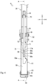
- FIG. 6
- is a rear view of the same;
- FIG. 7
- is a cross-sectional view taken along line A1 -A1;
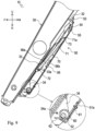
- FIG. 8
- is a side view illustrating the stand located at a storage position;
- FIG. 9
- is a side cross-sectional view of the same;
- FIG. 10
- is a side cross-sectional view illustrating an example of a state in which a left end portion of the spring and a pin abut on each other;
- FIG. 11
- is a side cross-sectional view illustrating a state in which the stand is further rocked downward from the state of
Fig. 10 ; - FIG. 12
- is a side cross-sectional view illustrating a state in which the stand is further rocked downward from the state of
Fig. 11 ; and - FIG. 13
- is a side cross-sectional view illustrating a state in which a position of a rocking shaft of the regulation member is changed from the state in
Fig. 7 . - In the following description, directions indicated by arrows U, D, F, B, L, and R in the drawings are defined as an upward direction, a downward direction, a forward direction, a backward direction, a left direction, and a right direction, respectively.
- Hereinafter, the entire configuration of a tractor 1 including a
front loader 10 according to one embodiment of the disclosure will be described. - As illustrated in
Fig. 1 , the tractor 1 mainly includes amachine body frame 2, anengine 3, atransmission case 4,front wheels 5, rear wheels 6, abonnet 7, a cabin 8, asteering wheel 9, and afront loader 10. - The
machine body frame 2 is a frame-shaped member formed by appropriately combining a plurality of panel members. Themachine body frame 2 is formed in a substantially rectangular shape in plan view. Themachine body frame 2 is disposed with its longitudinal direction oriented in a front-back direction. Theengine 3 is fixed to a rear portion of themachine body frame 2. Thetransmission case 4 is fixed to a rear portion of theengine 3. A front portion of themachine body frame 2 is supported by the pair of left and rightfront wheels 5 through a front axle mechanism (not illustrated). A rear portion of thetransmission case 4 is supported by the pair of left and right rear wheels 6 through a rear axle mechanism (not illustrated). Theengine 3 is covered with thebonnet 7. - Power of the
engine 3 can be transmitted to thefront wheels 5 through the front axle mechanism and can be transmitted to the rear wheels 6 through the rear axle mechanism after being shifted by a transmission device (not illustrated) accommodated in thetransmission case 4. Thefront wheels 5 and the rear wheels 6 are rotationally driven by the power of theengine 3, and the tractor 1 can travel. - The cabin 8 is provided behind the
engine 3. Inside the cabin 8, a living space on which an operator board is formed. In the living space, thesteering wheel 9 for adjusting a turning angle of thefront wheels 5, various operation tools, a seat on which the operator sits, and the like are disposed. - The
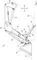
front loader 10 is mounted on a front portion of the tractor 1. Hereinafter, a detailed configuration of thefront loader 10 will be described with reference toFigs. 2 to 7 . Thefront loader 10 illustrated inFigs. 2 to 4 includes aside frame 20, aboom 30, abucket 40, astand 50, aspring 60, and aregulation member 70. - The
side frame 20 illustrated inFigs. 2 and3 is detachably attached to a vehicle body (themachine body frame 2 and the transmission case 4) of the tractor 1. The side frames 20 are provided on the left and right of the vehicle body. - The
booms 30 are rockably supported by the left and right side frames 20, respectively. Theboom 30 is disposed so as to extend forward and downward from an upper portion of theside frame 20. Theboom 30 is provided with aboom cylinder 31. Theboom 30 can rock with respect to theside frame 20 by extension and contraction of theboom cylinder 31. - Furthermore, the
boom 30 is provided with a member for supporting thestand 50 and theregulation member 70 described later. Specifically, as illustrated inFigs. 3 and4 , theboom 30 is provided with anengagement pin 32, anupper support portion 33, and alower support portion 34. - The
engagement pin 32 is a portion for engaging with thestand 50. Theengagement pin 32 is formed in a columnar shape. Theengagement pin 32 is fixed to a bottom surface of theboom 30 and is formed to extend rearward and downward from theboom 30. A tip portion of theengagement pin 32 is formed so that asnap pin 32a (seeFig. 4 ) can be attached. Note that, for convenience of description, thesnap pin 32a is omitted in the drawings except forFig. 4 . - The
upper support portion 33 illustrated inFigs. 4 and5 is a portion for supporting theregulation member 70. Theupper support portion 33 is formed in a substantially inverted U shape including a bottom portion along the bottom surface of theboom 30 and a pair of side portions extending downward from both left and right end portions of the bottom portion. Theupper support portion 33 is fixed to the bottom surface of theboom 30 and is disposed in front of and below theengagement pin 32. As illustrated inFig. 5 , a throughhole 33a penetrating in a left-right direction is formed in theupper support portion 33. A plurality of (three in the present embodiment) the throughholes 33a are formed along a longitudinal direction of theboom 30. Note that the number of the throughholes 33a is not limited to that in the present embodiment. - The
lower support portion 34 is a portion for supporting thestand 50. Thelower support portion 34 is formed in a substantially inverted U shape including a bottom portion of theboom 30 and a pair of side portions extending downward from both left and right end portions of the bottom portion (seeFig. 4 ). Thelower support portion 34 is fixed to the bottom surface of theboom 30 and is disposed in front of and below theupper support portion 33. As illustrated inFigs. 4 and7 , apin 34a whose axial direction is oriented in the left-right direction is inserted into thelower support portion 34. - The
bucket 40 illustrated inFigs. 2 and3 is formed to open forward. Thebucket 40 is rockably coupled to a front end portion of theboom 30. Furthermore, thebucket 40 is coupled to abucket cylinder 42 through alink mechanism 41. Thebucket 40 can rock with respect to theboom 30 by extension and contraction of thebucket cylinder 42. - The
stand 50 allows thefront loader 10 detached from the vehicle body of the tractor 1 to stand by itself. One stand 50 (a pair of right and left stands) is provided at each lower front portion of the right and leftbooms 30. Thestand 50 can be switched between a support position where the stand is in contact with the ground and capable of supporting thefront loader 10, and a storage position where the stand is stored at a position closer to theboom 30 than the support position. - Note that
Figs. 2 to 7 illustrate thestand 50 switched to the support position. Furthermore,Figs. 1 ,8 , and9 illustrate thestand 50 switched to the storage position. Hereinafter, the configuration of thestand 50 will be described with reference to a state where thestand 50 is at the support position. Note that, since thestand 50 has the same left and right configuration, thestand 50 on the left side will be described below as an example of the configuration of thestand 50. - As illustrated in
Figs. 4 and5 , thestand 50 includes a standmain body 51, a mainbody rocking shaft 52, a groundingportion 53, a groundingportion rocking shaft 54, a retainingportion 55, and anengagement portion 56. - The stand
main body 51 is provided to be rockable with respect to theboom 30. The standmain body 51 is formed in a longitudinal shape extending long in one direction (in a case where thestand 50 is in the support position, a rear downward direction from the boom 30). The standmain body 51 is formed in a substantially U shape with an opening facing upward in a longitudinal cross-sectional view. Furthermore, the standmain body 51 has a U-shaped cross section slightly larger than theupper support portion 33 and thelower support portion 34. A front end portion of the standmain body 51 is disposed so as to overlap thelower support portion 34 as viewed in a side view. As illustrated inFigs. 4 and7 , the standmain body 51 includes acutout portion 51a. - The
cutout portion 51a is a portion for hooking thespring 60 described later. Thecutout portion 51a is formed in a front portion of the standmain body 51. Thecutout portion 51a is formed from a bottom surface to a right side surface of the standmain body 51. - The main
body rocking shaft 52 rockably couples the standmain body 51 to theboom 30. The mainbody rocking shaft 52 is formed in a substantially columnar shape with an axis oriented to the left and right. The mainbody rocking shaft 52 is inserted through a front end portion of the standmain body 51 and thelower support portion 34. This enables the standmain body 51 to rock vertically with respect to theboom 30. The mainbody rocking shaft 52 is disposed behind thepin 34a of thelower support portion 34. - The grounding
portion 53 illustrated inFigs. 4 and5 is a portion that comes into contact with the ground when thefront loader 10 is supported by thestand 50. The groundingportion 53 is formed in a groove steel shape opened upward by bending both left and right end portions of a steel plate upward. The groundingportion 53 is disposed so as to overlap with a rear end portion of the standmain body 51 in a side view. As illustrated inFig. 4 , the groundingportion 53 includes ahole 53a. - The
hole 53a is formed so as to penetrate a bottom surface of the groundingportion 53. Thehole 53a is formed such that theengagement pin 32 of theboom 30 can be inserted therethrough. - The grounding
portion rocking shaft 54 illustrated inFigs. 4 and5 rockably couples the groundingportion 53 to the standmain body 51. The groundingportion rocking shaft 54 is formed in a substantially cylindrical shape with an axis oriented to the left and right. The groundingportion rocking shaft 54 is inserted through the standmain body 51 and the groundingportion 53. - The retaining
portion 55 illustrated inFigs. 4 and6 is provided for preventing theregulation member 70 from coming off from the standmain body 51. The retainingportion 55 is formed in a flat plate shape. The retainingportion 55 is fixed to the standmain body 51 and is disposed so as to cover a rear portion of the standmain body 51 from above. Anextension portion 55a extending forward and upward is formed on a left portion of the retainingportion 55. - The
engagement portion 56 illustrated inFig. 7 is a portion that engages with theregulation member 70 in a case where thestand 50 is at the support position. Theengagement portion 56 is provided at a middle portion in the front-back direction of the bottom surface of the standmain body 51. Theengagement portion 56 includes aguide portion 56a and arecess 56b. - The
guide portion 56a is a portion that guides theregulation member 70 to therecess 56b in accordance with the rocking of thestand 50. Theguide portion 56a is formed in a planar shape facing rearward. A plurality (four in the present embodiment) of theguide portions 56a are formed along the longitudinal direction of the standmain body 51. - The
recess 56b is a portion that can abut on theregulation member 70. Therecess 56b is formed in a substantially arc shape (curved surface shape) in side view. A plurality (four in the present embodiment) of therecesses 56b are formed along the longitudinal direction of the standmain body 51. Furthermore, therecesses 56b are formed so as to be alternately continuous with theguide portions 56a. Note that the number of theguide portions 56a and the number of therecesses 56b are not limited to the present embodiment. - The
spring 60 illustrated inFigs. 4 ,6 , and7 biases thestand 50 upward (in a direction approaching the boom 30). Thespring 60 is constituted by a winding spring externally fitted to the mainbody rocking shaft 52 inside the standmain body 51. A right end portion (one end portion) 61 of thespring 60 is formed so as to extend backward and downward, and is hooked on thecutout portion 51a of the standmain body 51. Furthermore, a left end portion (the other end portion) 62 of thespring 60 is formed so as to extend forward and upward, and protrudes from the standmain body 51. Theleft end portion 62 can abut on thepin 34a of the lower support portion 34 (seeFig. 7 ). - In a case where the
stand 50 is in the support position, thespring 60 is deformed between the standmain body 51 and thepin 34a to bias thestand 50 upward (in a counterclockwise direction in a left side view about the main body rocking shaft 52). - The
regulation member 70 illustrated inFigs. 4 to 6 is for regulating upward rocking of thestand 50. Theregulation member 70 includes amain body 71, a rockingshaft 72, and a pin 73 (seeFig. 6 ). - The
main body 71 is formed in a quadrangular prism shape extending long in one direction (a rear downward direction from the boom 30). A horizontal width of themain body 71 is smaller than a horizontal width of the standmain body 51. Furthermore, a length of themain body 71 is shorter than a length of the standmain body 51. In this way, themain body 71 is formed so as to be storable in the standmain body 51. - As illustrated in
Fig. 7 , a proximal end portion (upper end portion) and adistal end portion 71a (lower end portion) of themain body 71 are formed in a substantially arc shape in a side view. Therecess 56b of thestand 50 described above is formed in a substantially arc shape in a side view along thedistal end portion 71a. As a result, a contact area between thedistal end portion 71a and therecess 56b can be increased. Note that the shapes of thedistal end portion 71a and therecess 56b are not limited to the present embodiment, and can be arbitrarily changed. - As illustrated in
Figs. 5 and6 , the proximal end portion of themain body 71 is disposed in theupper support portion 33. A middle portion of themain body 71 is disposed so as to overlap with a left and right central portion of the standmain body 51 in rear view. On the other hand, the middle portion of themain body 71 is disposed on the right side of theextension portion 55a so as not to overlap with theextension portion 55a of the retainingportion 55 in rear view. As illustrated inFigs. 6 and7 , thedistal end portion 71a of themain body 71 is disposed in the standmain body 51. Thedistal end portion 71a abuts on therecess 56b (thethird recess 56b from the rear inFig. 7 ) of theengagement portion 56. - The rocking
shaft 72 is for rockably supporting themain body 71 with respect to theboom 30. The rockingshaft 72 is formed in a columnar shape with its axis oriented to the left and right (direction parallel to the main body rocking shaft 52). The rockingshaft 72 is inserted through theupper support portion 33 and themain body 71. More specifically, the rockingshaft 72 is inserted into any one of the plurality of throughholes 33a formed in the upper support portion 33 (the most front throughhole 33a inFig. 7 ) and the proximal end portion of themain body 71. - The
pin 73 is a portion that can abut on theextension portion 55a of the retainingportion 55. Thepin 73 is formed in a columnar shape with its axis oriented to the left and right. Thepin 73 is fixed to thedistal end portion 71a of themain body 71 and protrudes leftward from themain body 71. Thepin 73 is disposed so as to overlap with theextension portion 55a in rear view. - Hereinafter, a state of the
stand 50 disposed at the storage position (mainly a difference from the case of the support position) will be described. Thestand 50 is rocked upward from the support position illustrated inFig. 5 to be switched to the storage position illustrated inFig. 8 . - In a case where the
stand 50 is at the storage position, the standmain body 51 is inclined rearward and upward along theboom 30. Furthermore, theengagement pin 32 is inserted into the grounding portion 53 (hole 53a illustrated inFig. 4 ). When thesnap pin 32a (seeFig. 4 ) is attached to theengagement pin 32 in this state, the groundingportion 53 is fixed to theengagement pin 32, and thestand 50 is held by theboom 30 at the storage position. - Furthermore, as illustrated in
Fig. 9 , in a case where thestand 50 is at the storage position, theregulation member 70 is stored in the standmain body 51 in a posture inclined rearward and upward. Thedistal end portion 71a of theregulation member 70 does not abut on therecess 56b and is located above therecess 56b. - In a case where the
stand 50 is in the storage position, theright end portion 61 of thespring 60 is hooked on thecutout portion 51a of the standmain body 51 similarly to the case of the support position (seeFig. 7 ). Unlike the case of the support position, theleft end portion 62 of thespring 60 does not abut on thepin 34a of thelower support portion 34 and is located below thepin 34a. As described above, unlike the case of the support position, thespring 60 is not deformed between the standmain body 51 and thepin 34a, and does not bias thestand 50. - A procedure for switching the
stand 50 from the storage position to the support position will be described below. For example, the operator switches thestand 50 from the storage position to the support position in order to make thefront loader 10 removed from the tractor 1 (vehicle body) stand by itself. The position of thestand 50 is switched before thefront loader 10 is removed from the tractor 1. - First, the operator removes the
snap pin 32a (seeFig. 4 ) from theengagement pin 32 to release the engagement between the groundingportion 53 and theengagement pin 32 illustrated inFig. 8 . Next, the operator gradually rocks the standmain body 51 downward while supporting the standmain body 51. At this time, themain body 71 of theregulation member 70 illustrated inFig. 9 rocks downward by its own weight. By the rotation, thedistal end portion 71a of themain body 71 approaches theengagement portion 56. Furthermore, thespring 60 rotates in the clockwise direction in the left side view as the standmain body 51 rocks. Theleft end portion 62 of thespring 60 moves upward by the rotation and approaches thepin 34a. - As illustrated in
Fig. 10 , theleft end portion 62 of thespring 60 abuts on thepin 34a when the standmain body 51 is rocked downward by a predetermined angle. When the standmain body 51 is further rocked downward from this state, theright end portion 61 moves relative to theleft end portion 62 in the clockwise direction in the left side view, and thespring 60 is deformed. Thespring 60 thus biases the standmain body 51 upward from the middle of thestand 50 moving toward the support position. The operator further rocks the standmain body 51 downward while continuously supporting the standmain body 51. - Note that, as the stand
main body 51 is rocked downward from the state ofFig. 10 , a deformation amount of thespring 60 increases, and a biasing force of thespring 60 increases. -
Fig. 11 illustrates an example of a state in which the standmain body 51 is rocked downward from the state ofFig. 10 , and the biasing force of thespring 60 and the weight of thestand 50 are balanced. In the state illustrated inFig. 11 , thedistal end portion 71a of theregulation member 70 is not engaged with therecess 56b of theengagement portion 56 and is located behind therecess 56b. - As illustrated in
Fig. 11 , when the standmain body 51 is rocked downward until the biasing force of thespring 60 and the weight of thestand 50 are balanced, even if the operator releases his/her hand from the standmain body 51, the standmain body 51 is held by thespring 60. - The operator further rocks the stand
main body 51 downward from the state ofFig. 11 . For example, the operator steps on the rear portion of thestand 50 or pushes the rear portion by hand to further rock thestand 50 downward against the biasing force of thespring 60. At this time, themain body 71 of theregulation member 70 rocks downward by its own weight. As a result, thedistal end portion 71a of themain body 71 comes into contact with theengagement portion 56 and slides over theguide portion 56a of theengagement portion 56. Thus, as illustrated inFig. 12 , thedistal end portion 71a abuts on therecess 56b of theengagement portion 56. - In this state, the biasing force of the
spring 60 is larger than the weight of thestand 50, so that the standmain body 51 tends to rock upward. In contrast, theregulation member 70 is stretched between itself and theboom 30 to regulate upward rocking of the standmain body 51. In this way, thestand 50 is held at the support position. - In the present embodiment, in a case where the
stand 50 is at the support position, not only therecess 56b but also theguide portion 56a abuts on theregulation member 70, so that the contact area between thestand 50 and theregulation member 70 can be increased. As a result, the surface pressures of thestand 50 and theregulation member 70 can be suppressed (reduced), and deformation and breakage of thestand 50 and theregulation member 70 can be suppressed. - Furthermore, in the present embodiment, the
guide portion 56a and therecess 56b are alternately and continuously formed. Therefore, when the standmain body 51 rocks downward from the state ofFig. 12 , thedistal end portion 71a of theregulation member 70 gets over theguide portion 56a and abuts on therecess 56b located in front of the guide portion. - As described above, since the
stand 50 of the present embodiment is allowed to rock downward in a case where the stand is in the support position, the operator can easily change therecess 56b on which thedistal end portion 71a abuts only by further rocking the standmain body 51 in the state illustrated inFig. 12 downward. By changing therecess 56b in this way, the rocking angle of the standmain body 51 can be changed to adjust the groundingportion 53 to an appropriate height position. Hereinafter, an example of adjustment contents of the height position will be described. - In a case where the
front loader 10 is removed on an uneven ground, it is assumed that there is a height difference between a ground contact surface G1 of thebucket 40 illustrated inFig. 3 and a surface G2 on the rear side (stand 50 side) of the ground contact surface G1. For example, it is assumed that the surface G2 on the rear side is at a low position with respect to the ground contact surface G1. In this case, as illustrated inFig. 7 , thedistal end portion 71a of theregulation member 70 abuts on thefront recess 56b among the plurality ofrecesses 56b. As a result, the rocking angle of the standmain body 51 can be increased, and the height position of the groundingportion 53 can be set to a relatively low position. Accordingly, since the height position of the groundingportion 53 is appropriately adjusted according to the shape of the uneven ground, when thefront loader 10 is removed from the tractor 1, it is possible to suppress thefront loader 10 from tilting back and forth. - Furthermore, in a case where the
front loader 10 is removed on an uneven ground, it is also assumed that there is a height difference between the left and right of thefront loader 10. For example, it is assumed that the right side is at a higher position than the left side of thefront loader 10. In this case, the height position of the groundingportion 53 of thestand 50 on the left side is set higher than that on the right side. Specifically, theregulation member 70 on the left side abuts on therecess 56b on the relatively rear side (seeFig. 12 ), and theregulation member 70 on the right side abuts on therecess 56b on the relatively front side (seeFig. 7 ). Accordingly, when thefront loader 10 is removed from the tractor 1, it is possible to prevent thefront loader 10 from being inclined to the left and right. In this way, thefront loader 10 can be easily remounted on the tractor 1 by suppressing the front-back and right-left inclinations of thefront loader 10. - Furthermore, in the present embodiment, not only the
recesses 56b but also the plurality of throughholes 33a through which the rockingshaft 72 of theregulation member 70 can be inserted are formed. The worker can also change the height position of the groundingportion 53 by changing the throughholes 33a through which the rockingshaft 72 is inserted. - For example, when the rocking
shaft 72 is pulled out from the front throughhole 33a illustrated inFig. 7 and inserted into the throughhole 33a behind the front through hole, the rocking angle of the standmain body 51 can be reduced as illustrated inFig. 13 . As a result, the height position of the groundingportion 53 is adjusted without changing therecess 56b on which thedistal end portion 71a abuts. Furthermore, in the present embodiment, the height position of the groundingportion 53 is more finely adjusted in a case where the throughholes 33a are changed than a case where therecesses 56b are changed. - Furthermore, during this operation, since the
stand 50 is biased upward by thespring 60, the operator can change the position of the rocking shaft 72 (throughholes 33a) only by supporting thestand 50 with a light force. Furthermore, since each of therecesses 56b is formed in an arc shape in side view, even if the position of the rockingshaft 72 is changed, the contact area between thedistal end portion 71a and therecess 56b does not greatly change. As a result, it is possible to suppress a change in surface pressure between thestand 50 and theregulation member 70 according to the position of the rockingshaft 72. - As described above, in the present embodiment, two types of adjustment mechanisms (
recesses 56b, throughholes 33a) for adjusting the height of the groundingportion 53 are provided. According to this configuration, the height position of the groundingportion 53 can be finely adjusted by combining the position adjustments by the two types of adjustment mechanisms. - Here, for example, when the height position of the grounding
portion 53 is finely adjusted only by therecesses 56b, it is necessary to dispose a large number ofrecesses 56b in a narrow range, and the contact area between each of therecesses 56b and thedistal end portion 71a is reduced. Therefore, in the present embodiment, the adjustment in therecesses 56b is made relatively rough to suppress a decrease in the contact area, and the height position of the groundingportion 53 can be finely adjusted in combination with the throughholes 33a. As a result, the surface pressure between thestand 50 and theregulation member 70 can be suppressed, and the groundingportion 53 can be adjusted to a more appropriate height position. - Next, a procedure for switching from the support position to the storage position illustrated in
Fig. 7 will be described. The operator switches thestand 50 from the support position to the storage position in a case where thefront loader 10 does not need to stand by itself (for example, after thefront loader 10 is mounted on the tractor 1). - First, the operator rocks the stand
main body 51 downward while supporting theregulation member 70. As a result, the standmain body 51 is rocked downward with respect to theregulation member 70 to release the engagement between therecess 56b and thedistal end portion 71a. - Next, the operator lifts (rocks upward) the
regulation member 70 and the standmain body 51. The biasing force of thespring 60 acts on thestand 50 halfway from the support position to the storage position (SeeFig. 10 until thespring 60 returns to its original shape.), so that the operator can lift thestand 50 with a relatively light force. - When the operator lifts the
stand 50 to the storage position illustrated inFig. 8 , thestand 50 is fixed to theboom 30 by thesnap pin 32a (seeFig. 4 ). As a result, thestand 50 can be switched from the support position to the storage position. - In the present embodiment, the
stand 50 can be supported by thespring 60 when thestand 50 is used (when the support position and the storage position are switched). Thus, the operator can rock thestand 50 with a light force. Furthermore, the work can be performed in a reasonable posture. For example, the work can be performed without holding thestand 50 at a relatively low position while squatting down. As a result, the burden on the operator when using thestand 50 can be reduced, and workability can be improved. - Furthermore, in the present embodiment, since the retaining
portion 55 is provided in the standmain body 51, for example, even if the standmain body 51 largely rocks with respect to theregulation member 70, thepin 73 and themain body 71 of theregulation member 70 are caught by the retainingportion 55. By thus preventing theregulation member 70 from coming off from the standmain body 51, the standmain body 51 and theregulation member 70 can be easily rocked, and switching between the support position and the storage position can be easily performed. - As described above, the
front loader 10 according to the present embodiment includes thestand 50 that is provided, on theboom 30, rockably about the main body rocking shaft 52 (first rocking shaft) and is movable between a support position (positions illustrated inFigs. 2 to 7 ) where thefront loader 10 can be supported and a storage position (positions illustrated inFigs. 8 and9 ) where the stand is stored at a position closer to theboom 30 than the support position, and the spring 60 (biasing member) capable of biasing thestand 50 in a direction (upward) approaching theboom 30. - With such a configuration, it is possible to improve workability when the
stand 50 is used. - Furthermore, further included is the
regulation member 70 that is provided, on theboom 30, rockably about the rocking shaft 72 (second rocking shaft) parallel to the mainbody rocking shaft 52, and is capable of regulating rocking of thestand 50 in the direction (upward) approaching theboom 30 by abutting on thestand 50. - With such a configuration, since the
stand 50 can be held at a predetermined position with a simple configuration, maintainability can be improved, and cost can be reduced. - Furthermore, the
regulation member 70 includes thedistal end portion 71a formed in an arc shape as viewed in the axial direction (left-right direction) of the rockingshaft 72, and thestand 50 includes therecess 56b capable of abutting on thedistal end portion 71a of theregulation member 70 and formed in an arc shape along thedistal end portion 71a of theregulation member 70 as viewed in the axial direction (left-right direction) of the main body rocking shaft 52 (seeFig. 7 ). - With such a configuration, a relatively large contact area between the
regulation member 70 and thestand 50 can be secured, so that a surface pressure between both members can be suppressed, and deformation and breakage can be prevented. - Furthermore, the
stand 50 includes a plurality of therecesses 56b. - With such a configuration, the position of the
stand 50 can be adjusted by making theregulation member 70 abut on thearbitrary recess 56b. - Furthermore, the
boom 30 includes the upper support portion 33 (attachment portion) capable of attaching the rockingshaft 72 to a plurality of attachment positions (seeFig. 13 ). - With this configuration, the position of the
stand 50 can be adjusted by changing the attachment positions of the rockingshaft 72. - Furthermore, the
stand 50 includes the plurality ofrecesses 56b capable of abutting on thedistal end portion 71a of theregulation member 70, and theboom 30 includes the upper support portion 33 (attachment portion) capable of attaching the rockingshaft 72 to a plurality of attachment positions. - With this configuration, the position of the
stand 50 can be finely adjusted by the plurality of adjustment mechanisms. - Furthermore, the
spring 60 does not bias thestand 50 until thestand 50 rocks from the storage position toward the support position by a predetermined angle (seeFigs. 9 and10 ). - With such a configuration, it is possible to suppress fatigue of the
spring 60. For example, in the configuration in which the deformation amount of thespring 60 increases as the rocking angle of thestand 50 increases as in the present embodiment, thestand 50 is not biased until thestand 50 rocks by a predetermined angle, so that it is possible to suppress the deformation amount of thespring 60 from becoming excessively large. As a result, fatigue of thespring 60 can be suppressed. - Furthermore, as described above, the tractor 1 (working vehicle) according to the present embodiment includes the
front loader 10. - With such a configuration, it is possible to improve workability when the
stand 50 is used. - Note that the main
body rocking shaft 52 according to the present embodiment is an embodiment of the first rocking shaft according to the disclosure. - Furthermore, the
spring 60 according to the present embodiment is an embodiment of the biasing member according to the disclosure. - Furthermore, the rocking
shaft 72 according to the present embodiment is an embodiment of the second rocking shaft according to the disclosure. - Furthermore, the
upper support portion 33 according to the present embodiment is an embodiment of the attachment portion according to the disclosure. - Furthermore, the tractor 1 according to the present embodiment is an embodiment of the working vehicle according to the disclosure.
- Although the embodiments of the disclosure have been described above, the disclosure is not limited to the above configurations, and various modifications can be made within the scope of the invention described in the claims.
- For example, the working vehicle according to the present embodiment is the tractor 1, but the type of the working vehicle is not limited thereto. The working vehicle may be another agricultural vehicle, a construction vehicle, an industrial vehicle, or the like.
- Furthermore, although the
bucket 40 is coupled to theboom 30, the work tool coupled to theboom 30 is not limited to thebucket 40 and can be arbitrarily changed. For example, a snow blower, a snow blade, a sweeper, and the like may be coupled to theboom 30. - Furthermore, in the present embodiment, the two stands 50 (the pair of right and left stands) are provided, but the number of the
stands 50 is not limited. - Furthermore, although the
spring 60 is configured by a winding spring, the type of thespring 60 is not limited to the winding spring. - Furthermore, in the present embodiment, the
recess 56b abuts on thedistal end portion 71a of theregulation member 70, but thedistal end portion 71a may abut on a portion different from therecess 56b. For example, a through hole may be formed in the bottom surface of the standmain body 51, and thedistal end portion 71a may abut on (be inserted into) the through hole. As described above, the portion that can abut on thedistal end portion 71a is not limited to therecess 56b, and can be arbitrarily changed. - Furthermore, in the present embodiment, the height position of the grounding
portion 53 is adjusted by the two types of adjustment mechanisms (therecesses 56b and the throughholes 33a), but the number of adjustment mechanisms is not particularly limited. For example, the height position of the groundingportion 53 can be adjusted by one adjustment mechanism.
Claims (8)
- A front loader (10) comprising:- a stand (50) provided, on a boom (30), rockably about a first rocking shaft (52), the stand (50) being movable between a support position where the stand (50) is capable of supporting the front loader (10) and a storage position where the stand (50) is stored at a position closer to the boom (30) than the support position; and- a biasing member (60) capable of biasing the stand (50) in a direction approaching the boom (30).
- The front loader (10) as claimed in claim 1, further comprising a regulation member (70) provided, on the boom (30), rockably about a second rocking shaft (72) parallel to the first rocking shaft (52), the regulation member (70) being capable of regulating rocking of the stand (50) in the direction approaching the boom (30) by abutting on the stand (50).
- The front loader (10) as claimed in claim 2, wherein- the regulation member (70) includes a distal end portion formed in an arc shape as viewed in an axial direction of the second rocking shaft (72), and- the stand (50) includes a recess (56b) capable of abutting on the distal end portion of the regulation member (70) and formed in an arc shape along the distal end portion of the regulation member (70) as viewed in an axial direction of the first rocking shaft (52).
- The front loader (10) as claimed in claim 3, wherein the stand (50) includes a plurality of the recesses (56b).
- The front loader (10) as claimed in claim 3 or 4, wherein the boom (30) includes an attachment portion (33) capable of attaching the second rocking shaft (72) to a plurality of attachment positions.
- The front loader (10) as claimed in claim 2, wherein- the stand (50) includes a plurality of recesses (56b) capable of abutting on a distal end portion of the regulation member (70), and- the boom (30) includes an attachment portion (33) capable of attaching the second rocking shaft (72) to a plurality of attachment positions.
- The front loader (10) as claimed in any one of claims 1 to 6, wherein the biasing member (60) does not bias the stand (50) until the stand (50) rocks from the storage position toward the support position by a predetermined angle.
- A working vehicle comprising the front loader (10) as claimed in any one of claims 1 to 7.
Applications Claiming Priority (1)
| Application Number | Priority Date | Filing Date | Title |
|---|---|---|---|
| JP2023174483A JP2025064597A (en) | 2023-10-06 | 2023-10-06 | Front loaders and work vehicles |
Publications (1)
| Publication Number | Publication Date |
|---|---|
| EP4534760A1 true EP4534760A1 (en) | 2025-04-09 |
Family
ID=93013726
Family Applications (1)
| Application Number | Title | Priority Date | Filing Date |
|---|---|---|---|
| EP24204640.7A Pending EP4534760A1 (en) | 2023-10-06 | 2024-10-04 | Front loader and working vehicle |
Country Status (3)
| Country | Link |
|---|---|
| US (1) | US20250116082A1 (en) |
| EP (1) | EP4534760A1 (en) |
| JP (1) | JP2025064597A (en) |
Citations (4)
| Publication number | Priority date | Publication date | Assignee | Title |
|---|---|---|---|---|
| US7168907B2 (en) * | 2005-05-02 | 2007-01-30 | Deere & Company | Latching system for automatically securing front-mounted loader mast to tractor-carried loader mounting frame |
| JP2011012456A (en) | 2009-07-02 | 2011-01-20 | Yanmar Co Ltd | Loader working machine body |
| US10036138B1 (en) * | 2017-12-27 | 2018-07-31 | Kubota Corporation | Front loader and working machine with left and right wires |
| JP6552399B2 (en) * | 2015-12-07 | 2019-07-31 | 株式会社クボタ | Work vehicle and front loader |
-
2023
- 2023-10-06 JP JP2023174483A patent/JP2025064597A/en active Pending
-
2024
- 2024-10-01 US US18/903,121 patent/US20250116082A1/en active Pending
- 2024-10-04 EP EP24204640.7A patent/EP4534760A1/en active Pending
Patent Citations (4)
| Publication number | Priority date | Publication date | Assignee | Title |
|---|---|---|---|---|
| US7168907B2 (en) * | 2005-05-02 | 2007-01-30 | Deere & Company | Latching system for automatically securing front-mounted loader mast to tractor-carried loader mounting frame |
| JP2011012456A (en) | 2009-07-02 | 2011-01-20 | Yanmar Co Ltd | Loader working machine body |
| JP6552399B2 (en) * | 2015-12-07 | 2019-07-31 | 株式会社クボタ | Work vehicle and front loader |
| US10036138B1 (en) * | 2017-12-27 | 2018-07-31 | Kubota Corporation | Front loader and working machine with left and right wires |
Also Published As
| Publication number | Publication date |
|---|---|
| US20250116082A1 (en) | 2025-04-10 |
| JP2025064597A (en) | 2025-04-17 |
Similar Documents
| Publication | Publication Date | Title |
|---|---|---|
| US7635045B2 (en) | Machine tool control console | |
| US8434562B2 (en) | Ripper operating device | |
| JP4286183B2 (en) | Armrest device | |
| US9534354B2 (en) | Construction machine | |
| US20080023250A1 (en) | Ergonomic machine control console | |
| KR101114734B1 (en) | Riding type rice transplanter | |
| JP2019190024A (en) | Stand for front loader, front loader, and service vehicle | |
| JP7499685B2 (en) | Operation device for work vehicle | |
| US20250116082A1 (en) | Front loader and working vehicle | |
| JP2018199993A (en) | Front loader and working machine | |
| US10315534B2 (en) | Work vehicle | |
| JP4432234B2 (en) | Combine | |
| JP7812770B2 (en) | Work vehicle | |
| EP4424925A1 (en) | Cab and work machine | |
| JP2004000248A (en) | Combine | |
| JP2743425B2 (en) | Combine | |
| JP6891912B2 (en) | Transplant machine | |
| JP4330581B2 (en) | Work machine operation structure | |
| JP3570958B2 (en) | Crawler traveling type work vehicle | |
| JP2001322467A (en) | Driver's cab for construction machine | |
| KR102746067B1 (en) | Paddy field working machine | |
| JP3573225B2 (en) | Moving agricultural machine | |
| JP2024066981A (en) | Work equipment | |
| KR20260016421A (en) | Work vehicle | |
| JP2009148165A (en) | Combine |
Legal Events
| Date | Code | Title | Description |
|---|---|---|---|
| PUAI | Public reference made under article 153(3) epc to a published international application that has entered the european phase |
Free format text: ORIGINAL CODE: 0009012 |
|
| STAA | Information on the status of an ep patent application or granted ep patent |
Free format text: STATUS: THE APPLICATION HAS BEEN PUBLISHED |
|
| AK | Designated contracting states |
Kind code of ref document: A1 Designated state(s): AL AT BE BG CH CY CZ DE DK EE ES FI FR GB GR HR HU IE IS IT LI LT LU LV MC ME MK MT NL NO PL PT RO RS SE SI SK SM TR |
|
| STAA | Information on the status of an ep patent application or granted ep patent |
Free format text: STATUS: REQUEST FOR EXAMINATION WAS MADE |
|
| 17P | Request for examination filed |
Effective date: 20250814 |