EP4534756A1 - Method of controlling sheet manufacturing apparatus - Google Patents
Method of controlling sheet manufacturing apparatus Download PDFInfo
- Publication number
- EP4534756A1 EP4534756A1 EP24203815.6A EP24203815A EP4534756A1 EP 4534756 A1 EP4534756 A1 EP 4534756A1 EP 24203815 A EP24203815 A EP 24203815A EP 4534756 A1 EP4534756 A1 EP 4534756A1
- Authority
- EP
- European Patent Office
- Prior art keywords
- web
- roller
- tip end
- manufacturing apparatus
- transporting
- Prior art date
- Legal status (The legal status is an assumption and is not a legal conclusion. Google has not performed a legal analysis and makes no representation as to the accuracy of the status listed.)
- Granted
Links
Images

Classifications
-
- D—TEXTILES; PAPER
- D21—PAPER-MAKING; PRODUCTION OF CELLULOSE
- D21F—PAPER-MAKING MACHINES; METHODS OF PRODUCING PAPER THEREON
- D21F9/00—Complete machines for making continuous webs of paper
-
- D—TEXTILES; PAPER
- D21—PAPER-MAKING; PRODUCTION OF CELLULOSE
- D21G—CALENDERS; ACCESSORIES FOR PAPER-MAKING MACHINES
- D21G9/00—Other accessories for paper-making machines
- D21G9/0009—Paper-making control systems
- D21G9/0036—Paper-making control systems controlling the press or drying section
-
- D—TEXTILES; PAPER
- D21—PAPER-MAKING; PRODUCTION OF CELLULOSE
- D21G—CALENDERS; ACCESSORIES FOR PAPER-MAKING MACHINES
- D21G9/00—Other accessories for paper-making machines
- D21G9/0063—Devices for threading a web tail through a paper-making machine
-
- D—TEXTILES; PAPER
- D21—PAPER-MAKING; PRODUCTION OF CELLULOSE
- D21H—PULP COMPOSITIONS; PREPARATION THEREOF NOT COVERED BY SUBCLASSES D21C OR D21D; IMPREGNATING OR COATING OF PAPER; TREATMENT OF FINISHED PAPER NOT COVERED BY CLASS B31 OR SUBCLASS D21G; PAPER NOT OTHERWISE PROVIDED FOR
- D21H25/00—After-treatment of paper not provided for in groups D21H17/00 - D21H23/00
- D21H25/04—Physical treatment, e.g. heating, irradiating
Definitions
- the present disclosure relates to a method of controlling a sheet manufacturing apparatus.
- the sheet manufacturing apparatus of the present disclosure is not limited to be of the dry type but may also be of a wet type.
- the dry type is a mode implemented in air such as atmosphere without being implemented in a liquid.
- xyz axes are provided as coordinate axes that are orthogonal to one another.
- a direction indicated with each arrow will be defined as + direction while a direction opposite to the + direction will be defined as - direction.
- the z axis is a virtual axis extending along a vertical direction.
- +z direction is deemed to be upward while -z direction is deemed to be downward.
- the -z direction is equivalent to a direction of action of the gravity.
- a destination in a direction of transportation of raw materials, web, sheets, and the like may be referred to downstream while the other side to head back in the direction of transportation may be referred to upstream in some cases. Sizes of respective constituents may be different from actuality for the convenience of illustration.
- the sheet manufacturing apparatus 1 manufactures the sheet P3 from the used paper C being a material that contains fibers.
- the first unit group 101, the third unit group 103, and the second unit group 102 are arranged from the -y direction to the +y direction in side view from the -x direction.
- the used paper C is transported from the first unit group 101 to the second unit group 102 through a pipe 21 that traverses the inside of the third unit group 103. Then, the used paper C undergoes defibration and the like in the second unit group 102 so as to be converted into fibers, which are then formed into a mixture that contains a binding agent and the like.
- the mixture is transported to the third unit group 103 through a pipe 24.
- the mixture is formed into web W by the third unit group 103 and then shaped into a strip-shaped sheet P1.
- the strip-shaped sheet P1 is cut into the sheets P3 in the first unit group 101.
- the first unit group 101 includes a buffer tank 13, a volumetric feeder portion 15, a confluent portion 17, and the pipe 21. In the first unit group 101, these constituents are arranged in the enumerated order from the upstream to the downstream. Moreover, the first unit group 101 also includes a first cutting portion 81, a second cutting portion 82, a tray 84, and a shredding portion 86. The first cutting portion 81 and the second cutting portion 82 cut the strip-shaped sheet P1 into the sheets P3 in a predetermined shape. Furthermore, the first unit group 101 includes a water feeding portion 67. The water feeding portion 67 is a water storage tank. The water feeding portion 67 feeds water for humidification to each of a first humidifying portion 65 and a second humidifying portion 66 to be described later by using not-illustrated water feed pipes.
- the used paper C to be defibrated is temporarily stored in the buffer tank 13 and is then transported to the volumetric feeder portion 15 in accordance with an operation of the sheet manufacturing apparatus 1.
- the sheet manufacturing apparatus 1 may include a shredder located upstream of the buffer tank 13 and configured to shred the used paper C and the like.
- the volumetric feeder portion 15 includes a measure 15a and a not-illustrated feeding mechanism.
- the measure 15a measures the mass of the used paper C.
- the feeding mechanism feeds the used paper C measured with the measure 15a to the confluent portion 17 located downstream.
- the volumetric feeder portion 15 measures the used paper C into each predetermined mass with the measure 15a and feeds the measured used paper C to the confluent portion 17 located downstream by using the feeding mechanism.
- the measure 15a can adopt a measuring mechanism of a digital type or an analog type.
- the measure 15a may adopt a physical sensor such as a load cell, a spring scale, a balance, and the like.
- a load cell is used as the measure 15a.
- the predetermined mass of the used paper C to be measured with the measure 15a ranges from about several grams to several tens of grams, for example.
- the measurement and feeding operations of the used paper C by the volumetric feeder portion 15 are batch processes. In other words, the feeding of the used paper C from the volumetric feeder portion 15 to the confluent portion 17 is intermittently carried out.
- the volumetric feeder portion 15 may include two or more measures 15a, and may improve measurement efficiency by operating the measures 15a in a time-shifted fashion.
- the pipe 21 transports the used paper C from the first unit group 101 to the second unit group 102 by using an airflow generated by a not-illustrated blower.
- the used paper C transported in the pipe 21 flows into the defibrating portion 30.
- the defibrating portion 30 defibrates the used paper C being a material containing the fibers in a dry mode, thus generating a defibrated material containing the fibers.
- a publicly known defibration mechanism is applicable to the defibrating portion 30.
- a defibration mechanism provided with rotary blades is used as the defibrating portion 30.
- the defibration mechanism is configured to generate the fibers by shredding and defibrating the used paper C with the rotary blades.
- the used paper C is formed into the defibrated material containing the fibers by disentangling the entangled fibers contained in the used paper C by using the defibrating portion 30, and the defibrated material is transported to the separating portion 40.
- a publicly known separation mechanism is applicable to the separating portion 40.
- a disk-type separation mechanism provided with a separation filter is used as the separating portion 40.
- the separation mechanism is configured to sift and separate the relatively short fibers that pass through the separation filter from the relatively long fibers that do not pass through the separation filter.
- the relatively long fibers are used as the defibrated fibers, which is the material of the web W.
- the defibrated fibers are deprived of the relatively short fibers and the like by the separating portion 40. Then, the defibrated fibers are transported with an airflow, which is generated by a not-illustrated blower disposed at a tip end of the airflow pipe 29, to the mixing portion 91 through the pipe 23. Unwanted substances such as the relatively short fibers and the impurities are discharged to the collecting portion 95 through the pipe 25.
- the mixing portion 91 mixes the fiber with the binding agent and the like in the air, thereby forming the mixture.
- the mixing portion 91 includes a flow path to transport the fiber, a fan, a hopper, a supply pipe, and a valve.
- the fan in the mixing portion 91 generates an airflow so as to transport the fibers to the downstream and to mix the defibrated material with the binding agent and the like in the air at the same time, thus forming the mixture.
- the mixture flows from the mixing portion 91 into the pipe 24.
- the compressor 97 generates compressed air.
- the above-mentioned filter may cause clogging of fine particles and the like among the unwanted substances.
- the compressed air generated by the compressor 97 is caused to blow against the filter, so that the compressed air can blow the adhering particles away and clean the filter.
- the power source portion 99 includes a not-illustrated power supply device that supplies electric power to the sheet manufacturing apparatus 1, and a control unit 5.
- the power source portion 99 distributes the electric power supplied from outside to the respective structures in the sheet manufacturing apparatus 1.
- the third unit group 103 accumulates and compresses the mixture containing the fibers, thereby shaping the mixture into the strip-shaped sheet P1 which is recycled paper.
- the third unit group 103 includes an accumulating portion 50, a first transporting portion 61, the second transporting portion 62, the first humidifying portion 65, the air injecting portion 200, the second humidifying portion 66, a draining portion 68, and the pressing portion 70.
- the second transporting portion 62 is an example of a web transporting portion of the present disclosure.
- the first transporting portion 61 is disposed below the accumulating portion 50.
- the first transporting portion 61 includes a mesh belt 61a and five non-illustrated stretch rollers for stretching the mesh belt 61a.
- the suctioning portion 59 is opposed to the drum member 53 in the direction along the z axis while interposing the mesh belt 61a therebetween.
- the vane member 55 is located inside the drum member 53 and is rotationally driven by a not-illustrated motor.
- the drum member 53 is a sieve having a shape of a semicircular column.
- a mesh having a sieve function is provided on a side surface of the drum member 53 which is directed downward.
- the drum member 53 causes particles of the fibers and the mixture smaller than a size of mesh openings of the sieve to pass through the mesh from inside to outside.
- the mixture is agitated by the rotating vane member 55 inside the drum member 53 and is discharged to outside of the drum member 53.
- the humidified air is supplied from the second humidifying portion 66 into the drum member 53.
- the second transporting portion 62 transports the web W at the downstream of the first transporting portion 61 and instead of the first transporting portion 61.
- the second transporting portion 62 peels the web W off the upper surface of the mesh belt 61a, and transports the web W toward the pressing portion 70.
- the second transporting portion 62 is located above the transportation path for the web W and is disposed slightly on an upstream side relative to a point of origin on a return side of the mesh belt 61a.
- a portion in the +y direction of the second transporting portion 62 partially overlaps a portion in the -y direction of the mesh belt 61a in terms of the vertical direction.
- the suctioning portion 62b is located on the transportation path for the web W by the second transporting portion 62 and is disposed above the transporting belt 62a.
- the suctioning portion 62b suctions the air located below upward through the pores provided to the transporting belt 62a.
- one surface being an upper surface of the web W is suctioned toward a lower surface of the transporting belt 62a.
- the suctioning portion 62b is a publicly known suctioning device such as a suctioning fan.
- Humidification of the web W with the mist M facilitates a function of the binding agent included in the web W, thereby increasing the strength of the sheets P3. Meanwhile, since the web W is humidified from below, drips originating from the mist M are kept from dropping on the web W. Moreover, since the web W is humidified from an opposite side of the one surface of the web W that is in contact with the transporting belt 62a, adhesion of the web W to the transporting belt 62a is reduced. The second transporting portion 62 transports the web W toward the pressing portion 70.
- the air injecting portion 200 is located in the second transporting portion 62 and disposed downstream of the suctioning portion 62b. Although illustration is omitted, the air injecting portion 200 includes a pressurized air tank and an injection nozzle.
- the pressurized air tank supplies pressurized air to the injection nozzle.
- the air injecting portion 200 injects the pressurized air downward from the injection nozzle to the web W.
- the pressurized air is supplied from a not-illustrated compressor for the air injecting portion 200 and is stored in the pressurized air tank, for example.
- the injection nozzle is an elongate opening that extends in a direction along the x axis.
- the injection nozzle is opposed to the web W transported by the transporting belt 62a in a direction along the z axis.
- the pressurized air injected from the air injecting portion 200 passes through the transporting belt 62a and hits the one surface of the web W suctioned to the lower surface of the transporting belt 62a.
- a length of the injection nozzle is larger than a length of the web W in terms of the direction along the x axis. Accordingly, the pressurized air injected from the injection nozzle is sprayed on the entire width region of the web W.
- the pressing portion 70 includes a pair of pressing rollers 700 formed from a first roller 71 and a second roller 72.
- the pressing portion 70 passes the web W between the pair of pressing rollers 700, thereby forming the strip-shaped sheet P1 from the web W.
- the first roller 71 and the second roller 72 form the pair and each of the rollers is a member having a substantially columnar shape.
- a rotating shaft of the first roller 71 and a rotating shaft of the second roller 72 are arranged along the x axis.
- the first roller 71 is disposed almost below while the second roller 72 is disposed almost above.
- the first roller 71 and the second roller 72 are rotated while coming close to each other during formation of the strip-shaped sheet P1 from the web W.
- the first roller 71 includes a cored bar and a superficial layer that covers the cored bar, for example.
- a hollow structure formed from aluminum, iron, stainless steel, and the like can be cited as an example of the cored bar.
- a fluorine-containing resin such as polytetrafluoroethylene (PTFE), tetrafluoroethylene-perfluoroalkyl vinyl ether copolymer (PFA), tetrafluoroethylene-hexafluoropropylene copolymer (FEP), and tetrafluoroethylene-ethylene copolymer (ETFE), silicone resin, and the like can be cited as an example of a material of the superficial layer. In this way, releasability of the first roller 71 with respect to the web W is improved. In the meantime, this configuration suppresses wear and damage of the cored bar.
- PTFE polytetrafluoroethylene
- PFA tetrafluoroethylene-perfluoroalkyl vinyl ether copo
- a fluorine-containing resin such as polytetrafluoroethylene (PTFE), tetrafluoroethylene-perfluoroalkyl vinyl ether copolymer (PFA), tetrafluoroethylene-hexafluoropropylene copolymer (FEP), and tetrafluoroethylene-ethylene copolymer (ETFE) can be cited as an example of a material of the superficial layer.
- PTFE polytetrafluoroethylene
- PFA tetrafluoroethylene-perfluoroalkyl vinyl ether copolymer
- FEP tetrafluoroethylene-hexafluoropropylene copolymer
- ETFE tetrafluoroethylene-ethylene copolymer
- the web W is pressed in the course of passage between the first roller 71 and the second roller 72.
- a pressure from the first roller 71 and the second roller 72 to the web W is preferably equal to or above 0.1 MPa and equal to or below 15.0 MPa, more preferably equal to or above 0.2 MPa and equal to or below 10.0 MPa, or even more preferably equal to or above 0.4 MPa and equal to or below 8.0 MPa.
- deterioration of the fibers in the web W is suppressed.
- the first roller 71 has an electric heater built-in and has a function to increase the temperature on a surface of the roller. It is preferable to provide the second roller 72 with a function to increase the temperature on a surface of the roller with an electric heater as with the first roller 71.
- the second humidifying portion 66 is disposed below the first humidifying portion 65.
- a publicly known evaporative humidification device is applicable to the second humidifying portion 66.
- the second transporting portion 62 transports the web W downstream in the -y direction.
- the tip end of the web W is peeled off the transporting belt 62a by the pressurized air, and moreover, and the moving direction of the tip end of the web W is changed substantially downward. This facilitates bending of the tip end of the web W in the subsequent third step S3. Then, the operation proceeds to the third step S3.
- the first roller 71 is rotated in the rotational direction R1 being the first direction in the state where the tip end of the web W is in contact with the side surface of the first roller 71.
- the tip end of the web W is pulled by the rotation of the first roller 71 and is bent substantially in the +y direction.
- the second roller 72 is driven by the first roller 71 and is rotated in the counterclockwise rotational direction R2.
- rotation of the first roller 71 in the rotational direction R1 is set to a predetermined period.
- a distance of the tip end of the web W bent substantially in the +y direction is adjusted by a diameter, a rotational speed, and rotation time of the first roller 71.
- the time for rotating the first roller 71 in the rotational direction R1 is set to 3 seconds from the start of injection of the pressurized air from the air injecting portion 200.
- the tip end of the web W is bent in the +y direction in an amount approximately equal to 60 mm. Then, the operation proceeds to the fourth step S4.
- the first roller 71 is rotated in the rotational direction R2 being a second direction opposite to the first direction, and the second roller 72 is driven and rotated in the rotational direction R1.
- the web W is passed between the first roller 71 and the second roller 72 collectively constituting the pair of pressing rollers 700.
- the tip end of the web W is pressed and folded. Then, the operation proceeds to the fifth step S5.
- the tip end of the web W is not limited to be formed into the twofold.
- the tip end of the web W may be formed into a threefold or more by repeatedly carrying out the third step S3 and the fourth step S4 mentioned above.
- the thickness and strength at the tip end of the web W are further increased.
Landscapes
- Nonwoven Fabrics (AREA)
Abstract
Description
- The present application is based on, and claims priority from
JP Application Serial Number 2023-171149, filed October 2, 2023 - The present disclosure relates to a method of controlling a sheet manufacturing apparatus.
- There have heretofore been known apparatuses for manufacturing sheets by using fibers obtained by defibrating used paper and the like in air. Such apparatuses include one configured to shape a sheet from web containing fibers. For example,
JP-A-2014-208923 - However, the apparatus disclosed in
JP-A-2014-208923 - A method of controlling a sheet manufacturing apparatus is a method of controlling a sheet manufacturing apparatus configured to manufacture a sheet from a material containing a fiber, the sheet manufacturing apparatus being provided with a defibrating portion that defibrates the material containing the fiber and generates a defibrated material, an accumulating portion that forms web by accumulating the defibrated material, a web transporting portion that includes a transporting belt to come into contact with one surface of the web and to transport the web, and a pressing portion that includes a pair of pressing rollers formed from a first roller and a second roller, and forms the sheet by pressing the web, the method of controlling a sheet manufacturing apparatus including: a first step of transporting the web with the transporting belt; a second step of peeling a tip end of the web off the transporting belt; a third step of bending the tip end of the web by rotating the first roller in a first direction; and a fourth step of folding the tip end of the web by rotating the first roller in a second direction being opposite to the first direction and passing the web between the pair of pressing rollers.
-
-
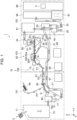
FIG. 1 is a schematic diagram illustrating a configuration of a sheet manufacturing apparatus according to an embodiment. -
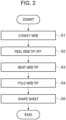
FIG. 2 is a flowchart illustrating a method of controlling the sheet manufacturing apparatus. -
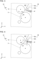
FIG. 3 is a schematic diagram illustrating a web folding method. -
FIG. 4 is another schematic diagram illustrating the web folding method. -
FIG. 5 is another schematic diagram illustrating the web folding method. -
FIG. 6 is another schematic diagram illustrating the web folding method. - The following embodiment exemplifies a
sheet manufacturing apparatus 1 of a dry type as a sheet manufacturing apparatus that manufactures sheets from a material containing fibers, which recycles slips of paper such as used paper into the sheets. Now, thesheet manufacturing apparatus 1 and a controlling method thereof will be described below with reference to the drawings. - Note that the sheet manufacturing apparatus of the present disclosure is not limited to be of the dry type but may also be of a wet type. In the present disclosure, the dry type is a mode implemented in air such as atmosphere without being implemented in a liquid.
- In the respective drawings cited below, xyz axes are provided as coordinate axes that are orthogonal to one another. A direction indicated with each arrow will be defined as + direction while a direction opposite to the + direction will be defined as - direction. The z axis is a virtual axis extending along a vertical direction. Here, +z direction is deemed to be upward while -z direction is deemed to be downward. The -z direction is equivalent to a direction of action of the gravity. Meanwhile, in the
sheet manufacturing apparatus 1, a destination in a direction of transportation of raw materials, web, sheets, and the like may be referred to downstream while the other side to head back in the direction of transportation may be referred to upstream in some cases. Sizes of respective constituents may be different from actuality for the convenience of illustration. - As illustrated in
FIG. 1 , thesheet manufacturing apparatus 1 according to the present embodiment includes afirst unit group 101, asecond unit group 102, and athird unit group 103. Thefirst unit group 101, thesecond unit group 102, and thethird unit group 103 are supported by a not-illustrated frame. InFIG. 1 , directions of movement of used paper C, sheets P3, slit pieces S, unnecessary listing, and the like are indicated with open arrows. - The
sheet manufacturing apparatus 1 manufactures the sheet P3 from the used paper C being a material that contains fibers. In thesheet manufacturing apparatus 1, thefirst unit group 101, thethird unit group 103, and thesecond unit group 102 are arranged from the -y direction to the +y direction in side view from the -x direction. - The used paper C is transported from the
first unit group 101 to thesecond unit group 102 through apipe 21 that traverses the inside of thethird unit group 103. Then, the used paper C undergoes defibration and the like in thesecond unit group 102 so as to be converted into fibers, which are then formed into a mixture that contains a binding agent and the like. The mixture is transported to thethird unit group 103 through apipe 24. The mixture is formed into web W by thethird unit group 103 and then shaped into a strip-shaped sheet P1. The strip-shaped sheet P1 is cut into the sheets P3 in thefirst unit group 101. - The
first unit group 101 includes abuffer tank 13, avolumetric feeder portion 15, aconfluent portion 17, and thepipe 21. In thefirst unit group 101, these constituents are arranged in the enumerated order from the upstream to the downstream. Moreover, thefirst unit group 101 also includes afirst cutting portion 81, asecond cutting portion 82, atray 84, and ashredding portion 86. Thefirst cutting portion 81 and thesecond cutting portion 82 cut the strip-shaped sheet P1 into the sheets P3 in a predetermined shape. Furthermore, thefirst unit group 101 includes awater feeding portion 67. Thewater feeding portion 67 is a water storage tank. Thewater feeding portion 67 feeds water for humidification to each of a first humidifyingportion 65 and a second humidifyingportion 66 to be described later by using not-illustrated water feed pipes. - The used paper C is put from a raw
material input slot 11 into thebuffer tank 13. The used paper C is a scrap of shredded used paper that contains fibers such as cellulose, for example. Humidified air is supplied from the second humidifyingportion 66 provided to thethird unit group 103 into thebuffer tank 13. - The used paper C to be defibrated is temporarily stored in the
buffer tank 13 and is then transported to thevolumetric feeder portion 15 in accordance with an operation of thesheet manufacturing apparatus 1. Thesheet manufacturing apparatus 1 may include a shredder located upstream of thebuffer tank 13 and configured to shred the used paper C and the like. - The
volumetric feeder portion 15 includes ameasure 15a and a not-illustrated feeding mechanism. Themeasure 15a measures the mass of the used paper C. The feeding mechanism feeds the used paper C measured with themeasure 15a to theconfluent portion 17 located downstream. In other words, thevolumetric feeder portion 15 measures the used paper C into each predetermined mass with themeasure 15a and feeds the measured used paper C to theconfluent portion 17 located downstream by using the feeding mechanism. - The
measure 15a can adopt a measuring mechanism of a digital type or an analog type. To be more precise, themeasure 15a may adopt a physical sensor such as a load cell, a spring scale, a balance, and the like. In the present embodiment, a load cell is used as themeasure 15a. The predetermined mass of the used paper C to be measured with themeasure 15a ranges from about several grams to several tens of grams, for example. - The feeding mechanism can adopt publicly known techniques such as a vibration feeder. The feeding mechanism may be incorporated in the
measure 15a. - The measurement and feeding operations of the used paper C by the
volumetric feeder portion 15 are batch processes. In other words, the feeding of the used paper C from thevolumetric feeder portion 15 to theconfluent portion 17 is intermittently carried out. Thevolumetric feeder portion 15 may include two ormore measures 15a, and may improve measurement efficiency by operating themeasures 15a in a time-shifted fashion. - In the
confluent portion 17, the shredded slit pieces S supplied from the shreddingportion 86 is put into and mixed with the used paper C fed from thevolumetric feeder portion 15. The slit pieces S and the shreddingportion 86 will be described later. The used paper C mixed with the above-mentioned shredded pieces flows from theconfluent portion 17 into thepipe 21. - The
pipe 21 transports the used paper C from thefirst unit group 101 to thesecond unit group 102 by using an airflow generated by a not-illustrated blower. - The
second unit group 102 includes adefibrating portion 30 being a dry-type defibrator, a separatingportion 40, apipe 23, a mixingportion 91, and thepipe 24. In thesecond unit group 102, these constituents are arranged in the enumerated order from the upstream to the downstream. Moreover, thesecond unit group 102 also includes a collectingportion 95, acompressor 97, apower source portion 99, apipe 25 that is connected to the separatingportion 40, and anairflow pipe 29. - The used paper C transported in the
pipe 21 flows into the defibratingportion 30. The defibratingportion 30 defibrates the used paper C being a material containing the fibers in a dry mode, thus generating a defibrated material containing the fibers. A publicly known defibration mechanism is applicable to thedefibrating portion 30. In the present embodiment, a defibration mechanism provided with rotary blades is used as the defibratingportion 30. The defibration mechanism is configured to generate the fibers by shredding and defibrating the used paper C with the rotary blades. - The used paper C is formed into the defibrated material containing the fibers by disentangling the entangled fibers contained in the used paper C by using the
defibrating portion 30, and the defibrated material is transported to the separatingportion 40. - The separating
portion 40 separates the defibrated fibers. Specifically, the separatingportion 40 removes certain components contained in the fibers, which are unnecessary for manufacturing the sheets P3. That is to say, the separatingportion 40 separates relatively long fibers from relatively short fibers. The relatively short fibers may cause a degradation in strength of the sheets P3, and are therefore sifted and eliminated by the separatingportion 40. Moreover, the separatingportion 40 also eliminates impurities such as coloring materials and additives contained in the used paper C. - A publicly known separation mechanism is applicable to the separating
portion 40. In the present embodiment, a disk-type separation mechanism provided with a separation filter is used as the separatingportion 40. The separation mechanism is configured to sift and separate the relatively short fibers that pass through the separation filter from the relatively long fibers that do not pass through the separation filter. The relatively long fibers are used as the defibrated fibers, which is the material of the web W. - The humidified air is supplied from the
second humidifying portion 66 of thethird unit group 103 into the separatingportion 40. - The defibrated fibers are deprived of the relatively short fibers and the like by the separating
portion 40. Then, the defibrated fibers are transported with an airflow, which is generated by a not-illustrated blower disposed at a tip end of theairflow pipe 29, to the mixingportion 91 through thepipe 23. Unwanted substances such as the relatively short fibers and the impurities are discharged to the collectingportion 95 through thepipe 25. - The mixing
portion 91 mixes the fiber with the binding agent and the like in the air, thereby forming the mixture. Although illustration is omitted, the mixingportion 91 includes a flow path to transport the fiber, a fan, a hopper, a supply pipe, and a valve. - The hopper communicates with the flow path for the fiber through the supply pipe. The valve is provided to the supply valve located between the hopper and the flow path. The hopper supplies the binding agent such as starch into the flow path. The valve adjusts a mass of the binding agent to be supplied from the hopper to the flow path. In this way, a mixture ratio of the fibers and the binding agent is adjusted.
- In addition to the aforementioned structure for supplying the binding agent, the mixing
portion 91 may include similar structured for supplying coloring agents, additives, and the like. - The fan in the mixing
portion 91 generates an airflow so as to transport the fibers to the downstream and to mix the defibrated material with the binding agent and the like in the air at the same time, thus forming the mixture. The mixture flows from the mixingportion 91 into thepipe 24. - The collecting
portion 95 includes a not-illustrated filter. The filter is configured to filter the unwanted substances such as the relatively short fibers transported in thepipe 25 by the airflow. - The
compressor 97 generates compressed air. The above-mentioned filter may cause clogging of fine particles and the like among the unwanted substances. The compressed air generated by thecompressor 97 is caused to blow against the filter, so that the compressed air can blow the adhering particles away and clean the filter. - The
power source portion 99 includes a not-illustrated power supply device that supplies electric power to thesheet manufacturing apparatus 1, and acontrol unit 5. Thepower source portion 99 distributes the electric power supplied from outside to the respective structures in thesheet manufacturing apparatus 1. - Although illustration is omitted, the
control unit 5 includes a central processing unit (CPU), and a storage unit that contains a random access memory (RAM), a read only memory (ROM), and so forth. Various programs for controlling thesheet manufacturing apparatus 1 are stored in the storage unit. Thecontrol unit 5 may include dedicated hardware (an application specific integrated circuit: ASIC) for executing at least part of various processing. Specifically, thecontrol unit 5 may be constructed as a circuit that includes one or more processors to be operated in accordance with computer programs (software), one or more dedicated hardware circuits such as the ASIC, or a combination of these constituents. - The processor includes the CPU, and a memory such as the RAM and the ROM. The memory stores program codes or instructions configured to cause the CPU to execute the processing. The memory, namely, a computer-readable medium includes any media accessible to a general-purpose or special-purpose computer.
- The
control unit 5 is electrically coupled to respective structures in thesheet manufacturing apparatus 1 including a second transportingportion 62, anair injecting portion 200, and apressing portion 70, and integrally controls operations of these structures. In particular, thecontrol unit 5 also governs control related to folding of the web W to be described later. - The
third unit group 103 accumulates and compresses the mixture containing the fibers, thereby shaping the mixture into the strip-shaped sheet P1 which is recycled paper. Thethird unit group 103 includes an accumulatingportion 50, a first transportingportion 61, the second transportingportion 62, thefirst humidifying portion 65, theair injecting portion 200, thesecond humidifying portion 66, a drainingportion 68, and thepressing portion 70. Note that the second transportingportion 62 is an example of a web transporting portion of the present disclosure. - In the
third unit group 103, the accumulatingportion 50, the first transportingportion 61, the second transportingportion 62, thefirst humidifying portion 65, and thepressing portion 70 are arranged in the enumerated order from the upstream to the downstream. Theair injecting portion 200 is located inside the second transportingportion 62 and is disposed at a downstream end portion of a transportation path for the web W in the second transportingportion 62. Thesecond humidifying portion 66 is disposed below thefirst humidifying portion 65. - The accumulating
portion 50 forms the web W by accumulating the mixture generated from the defibrated material while using an air flow and a gravitational force. The accumulatingportion 50 includes a drum member 53, a vane member 55 installed in the drum member 53, ahousing 51 to house the drum member 53, and asuctioning portion 59. The mixture is taken from thepipe 24 into the drum member 53. - The first transporting
portion 61 is disposed below the accumulatingportion 50. The first transportingportion 61 includes amesh belt 61a and five non-illustrated stretch rollers for stretching themesh belt 61a. The suctioningportion 59 is opposed to the drum member 53 in the direction along the z axis while interposing themesh belt 61a therebetween. - The vane member 55 is located inside the drum member 53 and is rotationally driven by a not-illustrated motor. The drum member 53 is a sieve having a shape of a semicircular column. A mesh having a sieve function is provided on a side surface of the drum member 53 which is directed downward. The drum member 53 causes particles of the fibers and the mixture smaller than a size of mesh openings of the sieve to pass through the mesh from inside to outside.
- The mixture is agitated by the rotating vane member 55 inside the drum member 53 and is discharged to outside of the drum member 53. The humidified air is supplied from the
second humidifying portion 66 into the drum member 53. - The suctioning
portion 59 is disposed below the drum member 53. The suctioningportion 59 suctions the air inside thehousing 51 through pores provided to themesh belt 61a. Thus, an airflow that accumulates the mixture on themesh belt 61a is generated. The pores in themesh belt 61a cause the air to pass therethrough but hardly causes the fibers, the binding agent, and the like included in the mixture to pass therethrough. Accordingly, the mixture discharged to the outside of the drum member 53 is suctioned downward together with the air. The suctioningportion 59 is a publicly known suctioning device such as a suctioning fan. - The mixture is dispersed in the air inside the
housing 51 and is accumulated on an upper surface of themesh belt 61a by the gravitational force and the airflow generated by the suctioningportion 59. Hence, the mixture turns into the web W. - The
mesh belt 61a is an endless belt that is stretched around the five stretch rollers. Themesh belt 61a is rotated counterclockwise inFIG. 1 by rotation of the stretch rollers. In this way, the mixture is continuously accumulated on themesh belt 61a and the web W is thus formed. The web W contains relatively a lot of air and is softly puffed. The first transportingportion 61 transports the generated web W downstream by the rotation of themesh belt 61a. - The second transporting
portion 62 transports the web W at the downstream of the first transportingportion 61 and instead of the first transportingportion 61. The second transportingportion 62 peels the web W off the upper surface of themesh belt 61a, and transports the web W toward thepressing portion 70. The second transportingportion 62 is located above the transportation path for the web W and is disposed slightly on an upstream side relative to a point of origin on a return side of themesh belt 61a. A portion in the +y direction of the second transportingportion 62 partially overlaps a portion in the -y direction of themesh belt 61a in terms of the vertical direction. - The second transporting
portion 62 includes a transportingbelt 62a, four non-illustrated stretch rollers, and asuctioning portion 62b. The transportingbelt 62a is provided with pores that allows the air to pass therethrough. The transportingbelt 62a is stretched around the four stretch rollers and is rotated clockwise inFIG. 1 by rotation of the stretch rollers. - The
suctioning portion 62b is located on the transportation path for the web W by the second transportingportion 62 and is disposed above the transportingbelt 62a. Thesuctioning portion 62b suctions the air located below upward through the pores provided to the transportingbelt 62a. Thus, one surface being an upper surface of the web W is suctioned toward a lower surface of the transportingbelt 62a. By rotating the transportingbelt 62a in this state, the web W is suctioned to the transportingbelt 62a and transported downstream. In other words, the transportingbelt 62a comes into contact with the one surface of the web W and transports the web W. Thesuctioning portion 62b is a publicly known suctioning device such as a suctioning fan. - The
first humidifying portion 65 humidifies the web W containing the fibers accumulated by the accumulatingportion 50 of thethird unit group 103. Specifically, thefirst humidifying portion 65 is a mist-type humidifier configured to supply mist M from below to the web W transported by the second transportingportion 62, thereby humidifying the web W. Thefirst humidifying portion 65 is disposed below the second transportingportion 62 and is opposed to the web W, which is transported by the second transportingportion 62, in the direction along the z axis. A publicly known humidification device such as an ultrasonic humidifier is applicable to thefirst humidifying portion 65. - Humidification of the web W with the mist M facilitates a function of the binding agent included in the web W, thereby increasing the strength of the sheets P3. Meanwhile, since the web W is humidified from below, drips originating from the mist M are kept from dropping on the web W. Moreover, since the web W is humidified from an opposite side of the one surface of the web W that is in contact with the transporting
belt 62a, adhesion of the web W to the transportingbelt 62a is reduced. The second transportingportion 62 transports the web W toward thepressing portion 70. - The
air injecting portion 200 is located in the second transportingportion 62 and disposed downstream of thesuctioning portion 62b. Although illustration is omitted, theair injecting portion 200 includes a pressurized air tank and an injection nozzle. The pressurized air tank supplies pressurized air to the injection nozzle. Theair injecting portion 200 injects the pressurized air downward from the injection nozzle to the web W. The pressurized air is supplied from a not-illustrated compressor for theair injecting portion 200 and is stored in the pressurized air tank, for example. - The injection nozzle is an elongate opening that extends in a direction along the x axis. The injection nozzle is opposed to the web W transported by the transporting
belt 62a in a direction along the z axis. The pressurized air injected from theair injecting portion 200 passes through the transportingbelt 62a and hits the one surface of the web W suctioned to the lower surface of the transportingbelt 62a. In this instance, a length of the injection nozzle is larger than a length of the web W in terms of the direction along the x axis. Accordingly, the pressurized air injected from the injection nozzle is sprayed on the entire width region of the web W. - In this way, the web W is peeled off the transporting
belt 62a. The injection of the pressurized air by theair injecting portion 200 is carried out when a tip end on the downstream side of the web W reaches a region opposed to theair injecting portion 200. Then, after the aforementioned tip end of the web W is peeled off the transportingbelt 62a, an operation to bend the tip end of the web W and an operation to fold the tip end of the web W are carried out. Thereafter, the web W is delivered from the second transportingportion 62 to thepressing portion 70. Details of the bending and the folding operations of the web W will be described later. - The
pressing portion 70 includes a pair of pressingrollers 700 formed from afirst roller 71 and asecond roller 72. Thepressing portion 70 passes the web W between the pair of pressingrollers 700, thereby forming the strip-shaped sheet P1 from the web W. - The
first roller 71 and thesecond roller 72 form the pair and each of the rollers is a member having a substantially columnar shape. A rotating shaft of thefirst roller 71 and a rotating shaft of thesecond roller 72 are arranged along the x axis. With respect to the transportation path for the web W, thefirst roller 71 is disposed almost below while thesecond roller 72 is disposed almost above. Thefirst roller 71 and thesecond roller 72 are rotated while coming close to each other during formation of the strip-shaped sheet P1 from the web W. - In the direction along the x axis, a length of the
first roller 71 and a length of thesecond roller 72 are larger than the length of the web W, or in other words, the width of the web W. Accordingly, the web W is securely caught between thefirst roller 71 and thesecond roller 72. - A diameter of the
first roller 71 is larger than a diameter of thesecond roller 72. For example, the diameter of thefirst roller 71 is equal to or above 110 mm and equal to or below 150 mm, and the diameter of thesecond roller 72 is equal to or above 80 mm and equal to or below 110 mm. - The
first roller 71 includes a cored bar and a superficial layer that covers the cored bar, for example. A hollow structure formed from aluminum, iron, stainless steel, and the like can be cited as an example of the cored bar. A fluorine-containing resin such as polytetrafluoroethylene (PTFE), tetrafluoroethylene-perfluoroalkyl vinyl ether copolymer (PFA), tetrafluoroethylene-hexafluoropropylene copolymer (FEP), and tetrafluoroethylene-ethylene copolymer (ETFE), silicone resin, and the like can be cited as an example of a material of the superficial layer. In this way, releasability of thefirst roller 71 with respect to the web W is improved. In the meantime, this configuration suppresses wear and damage of the cored bar. - The
second roller 72 includes a cored bar, an intermediate layer, and a superficial layer, for example. A hollow structure formed from aluminum, iron, stainless steel, and the like can be cited as an example of the cored bar. The intermediate layer covers the cored bar and is covered by the superficial layer. In other words, the intermediate layer is interposed between the cored bar and the superficial layer. - An elastic body such as silicone rubber and urethane rubber can be cited as an example of a material of the intermediate layer. Hardness of the aforementioned elastic body is preferably equal to or above 30 and equal to or below 70, or more preferably equal to or above 40 and equal to or below 60 in terms of a measurement value with an Asker C hardness scale. A thickness of the intermediate layer is preferably equal to or above 1 mm and equal to or below 10 mm, or more preferably equal to or above 1 mm and equal to or below 5 mm.
- A fluorine-containing resin such as polytetrafluoroethylene (PTFE), tetrafluoroethylene-perfluoroalkyl vinyl ether copolymer (PFA), tetrafluoroethylene-hexafluoropropylene copolymer (FEP), and tetrafluoroethylene-ethylene copolymer (ETFE) can be cited as an example of a material of the superficial layer.
- When the
second roller 72 adopts the above-described configuration, releasability of thesecond roller 72 with respect to the web W is improved. In the meantime, this configuration suppresses wear and damage of the intermediate layer. - The web W is pressed in the course of passage between the
first roller 71 and thesecond roller 72. A pressure from thefirst roller 71 and thesecond roller 72 to the web W is preferably equal to or above 0.1 MPa and equal to or below 15.0 MPa, more preferably equal to or above 0.2 MPa and equal to or below 10.0 MPa, or even more preferably equal to or above 0.4 MPa and equal to or below 8.0 MPa. Thus, deterioration of the fibers in the web W is suppressed. - The
first roller 71 has an electric heater built-in and has a function to increase the temperature on a surface of the roller. It is preferable to provide thesecond roller 72 with a function to increase the temperature on a surface of the roller with an electric heater as with thefirst roller 71. - A surface temperature of the
first roller 71, that is to say, a temperature of the superficial layer of thefirst roller 71 that comes into contact with the web W is preferably set equal to or above 100°C and equal to or below 130°C. A surface temperature of thesecond roller 72, that is to say, a temperature of the superficial layer of thesecond roller 72 that comes into contact with the web W is preferably set equal to or above 80°C and equal to or below 100°C. - The surface of the
first roller 71 has fine asperities. The asperities on the surface adopt surface roughness measured with a surface roughness meter as an indicator. The surface roughness of the surface of thefirst roller 71 is preferably equal to or above 2 µm and equal to or below 8 µm, or more preferably equal to or above 3 µm and equal to or below 6 µm in terms of arithmetic average roughness (Ra). On the other hand, the surface roughness is preferably equal to or above 15 µm and equal to or below 70 µm, or more preferably equal to or above 25 µm and equal to or below 50 µm in terms of the maximum height (Rz). The asperities on the surface of thefirst roller 71 may originate from a surface of the core bar or may originate from a surface of the superficial layer. These asperities are formed by blasting or thermal spraying, for example. - The
second roller 72 includes the elastic intermediate layer as described above. Accordingly, when the web W is shaped by pinching the web W between thefirst roller 71 and thesecond roller 72, the asperities are apt to develop on the surface of the strip-shaped sheet P1 which comes into contact with thesecond roller 72. On the other hand, if the surface of thefirst roller 71 is made flat and smooth, the surface of the strip-shaped sheet P1 that comes into contact with thefirst roller 71 is apt to be flat and smooth. In this case, top and bottom surfaces of the strip-shaped sheet P1 are prone to bring about a difference in surface quality. This difference in surface quality may bring about a difference in smoothness between top and bottom surfaces of the sheet P3, and the top and bottom surfaces of the sheet P3 may need to be distinguished from each other when the sheet P3 is used as copy paper and the like. - On the other hand, the above-mentioned fine asperities on the surface of the
first roller 71 reduces the difference in surface quality between the top and bottom surfaces of the strip-shaped sheet P1, so that the sheet P3 can be used without distinguishing between the top and bottom surfaces thereof. Moreover, followability of the web W with respect to thefirst roller 71 is improved in the course of bending the web W to be described later, so that the web W can be bent easily. - The
first roller 71 is rotationally driven by a stepping motor unillustrated. Thesecond roller 72 is a driven roller which is not driven by a motor but works in conjunction with the rotation of thefirst roller 71. Accordingly, thesecond roller 72 is rotated in a direction opposite to that of thefirst roller 71 in side view from the -x direction. - The web W is heated and pressed while being pinched between the
first roller 71 and thesecond roller 72, and is sent downstream. In other words, the web W is continuously passed through thepressing portion 70, thereby being heated and press-formed. The web W is heated and pressed efficiently by using thefirst roller 71 and thesecond roller 72 as a pair of shaping members. - Having passed through the
pressing portion 70, the web W is changed from a soft state of containing relatively a lot of air to a state of an increased density with reduction of the air contained therein. Then, the fibers are bonded to one another with the bonding agent and the web W is shaped into the strip-shaped sheet P1. The strip-shaped sheet P1 is transported to thefirst unit group 101 by using not-illustrated rollers. - Here, the web W is formed by accumulating the mixture. Accordingly, the thickness of the web W is unstable in an initial stage of forming the web W, or in other words, in a region at the tip end of the web W. In general, the thickness at the tip end of the web W tends to be smaller than a thickness of a subsequent portion. If the aforementioned thickness is small, there is a possibility of incurring a problem such as adhesion to the
first roller 71 or thesecond roller 72 and clogging of the strip-shaped sheet P1 in a path. On the other hand, in thesheet manufacturing apparatus 1, the occurrence of the above-mentioned problem is prevented by doubling the tip end and increasing the thickness thereof in accordance with a controlling method to be described later. In the following description, a tip end on the downstream side in the direction of transportation of the web W may be simply referred to as the tip end of the web W in some cases. - The
second humidifying portion 66 is disposed below thefirst humidifying portion 65. A publicly known evaporative humidification device is applicable to thesecond humidifying portion 66. - The
second humidifying portion 66 humidifies a predetermined region of thesheet manufacturing apparatus 1. The predetermined region includes one or more of thebuffer tank 13, the separatingportion 40, and the drum member 53 of the accumulatingportion 50. To be more precise, the humidified air is supplied from thesecond humidifying portion 66 to the above-mentioned region by the intermediary of not-illustrated pipes. The humidified air suppresses electrostatic charge of the used paper C, the fibers, and the like in the respective constituents mentioned above, thus curbing adhesion of these substances to the aforementioned members due to the static electricity. - The draining
portion 68 is a drain tank. The drainingportion 68 collects and stores old water used by thefirst humidifying portion 65, thesecond humidifying portion 66, and the like. The drainingportion 68 can be detached from thesheet manufacturing apparatus 1 as needed, so as to dispose of the water stored therein. - The strip-shaped sheet P1 transported to the
first unit group 101 reaches thefirst cutting portion 81. Thefirst cutting portion 81 cuts the strip-shaped sheet P1 in a direction orthogonal to the direction of transportation, or in a direction along the x axis, for example. The strip-shaped sheet P1 is cut into single-sheet-shaped sheets P2 by thefirst cutting portion 81. The single-sheet-shaped sheets P2 are transported from thefirst cutting portion 81 to thesecond cutting portion 82. - The
second cutting portion 82 cuts each single-sheet-shaped sheet P2 in the direction of transportation, or in a direction along the y axis, for example. Specifically, thesecond cutting portion 82 cuts out two end portions in the x axis direction of the single-sheet-shaped sheet P2. Thus, the single-sheet-shaped sheet P2 is formed into the sheet P3 in a predetermined shape such as the A4 size and the A3 size. - The slit pieces S being the listing are generated when the
second cutting portion 82 cuts the single-sheet-shaped sheet P2 into the sheets P3. The slit pieces S are transported substantially in the -y direction and reach the shreddingportion 86 which is the shredder. The shreddingportion 86 shreds the slit pieces S into shredded pieces, and supplies the shredded pieces to theconfluent portion 17. A mechanism for measuring the shredded slit pieces S and to feed the shredded pieces to theconfluent portion 17 may be installed between the shreddingportion 86 and theconfluent portion 17. - The sheets P3 are transported substantially upward and stacked on the
tray 84. The sheets P3 are manufactured by thesheet manufacturing apparatus 1 as described above. For example, the sheets P3 can adopt as an alternative to copy paper and the like. - As illustrated in
FIG. 2 , the method of controlling thesheet manufacturing apparatus 1 according to the present embodiment includes a first step S1, a second step S2, a third step S3, a fourth step S4, and a fifth step S5. These steps are executed in the enumerated order in accordance with control by thecontrol unit 5. Now, the respective steps will be described below with reference toFIGs. 3 to 6 . The description with reference toFIGs. 3 to 6 will discuss states in side view from the -x direction unless otherwise specified. - As illustrated in
FIG. 3 , in the first step S1, the second transportingportion 62 transports the web W downstream in the -y direction. - In the original shaping operation to pass the web W between the
first roller 71 and thesecond roller 72, thefirst roller 71 is rotated in a counterclockwise rotational direction R2 while thesecond roller 72 is rotated in a clockwise rotational direction R1. In the first step S1, the web W does not reach a point between thefirst roller 71 and thesecond roller 72. Accordingly, the rotation of thefirst roller 71 and thesecond roller 72 may be stopped or thefirst roller 71 and thesecond roller 72 may be rotated in the aforementioned directions as illustrated inFIG. 3 , respectively. - Then, the operation proceeds to the second step S2 at a point when the tip end of the web W goes beyond a region opposed to the
air injecting portion 200. Here, a method of determination as to whether or not the tip end of the web W reaches the region opposed to theair injecting portion 200 is fulfilled by detecting the position of the tip end of the web W by using an optical sensor. Meanwhile, as another method, it is also possible to adopt a method of carrying out a measurement of time required from a point when the accumulatingportion 50 starts driving to a point when the tip end of the web W reaches the position to oppose theair injecting portion 200 in advance, and conducting timing control while presetting the measured time. - As illustrated in
FIG. 4 , in the second step S2, the tip end of the web W is peeled off the transportingbelt 62a. Specifically, in the second step S2, the tip end of the web W is peeled off the transportingbelt 62a by injecting the pressurized air from theair injecting portion 200. The transportation of the web W by the transportingbelt 62a is continued during this period. Accordingly, the tip end of the web W is suspended downward and comes into contact with thefirst roller 71. - In this instance, as illustrated in
FIG. 4 , it is preferable to rotate thefirst roller 71 in the clockwise rotational direction R1 being a first direction before the operation transitions to the subsequent third step S3. In that case, thesecond roller 72 is driven by thefirst roller 71 and is rotated in the counterclockwise rotational direction R2. - In the second step S2, the tip end of the web W is peeled off the transporting
belt 62a by the pressurized air, and moreover, and the moving direction of the tip end of the web W is changed substantially downward. This facilitates bending of the tip end of the web W in the subsequent third step S3. Then, the operation proceeds to the third step S3. - As illustrated in
FIG. 5 , in the third step S3, thefirst roller 71 is rotated in the rotational direction R1 being the first direction in the state where the tip end of the web W is in contact with the side surface of thefirst roller 71. The tip end of the web W is pulled by the rotation of thefirst roller 71 and is bent substantially in the +y direction. In this instance, thesecond roller 72 is driven by thefirst roller 71 and is rotated in the counterclockwise rotational direction R2. - In the third step S3, rotation of the
first roller 71 in the rotational direction R1 is set to a predetermined period. A distance of the tip end of the web W bent substantially in the +y direction is adjusted by a diameter, a rotational speed, and rotation time of thefirst roller 71. For example, the time for rotating thefirst roller 71 in the rotational direction R1 is set to 3 seconds from the start of injection of the pressurized air from theair injecting portion 200. Thus, the tip end of the web W is bent in the +y direction in an amount approximately equal to 60 mm. Then, the operation proceeds to the fourth step S4. - As illustrated in
FIG. 6 , in the fourth step S4, thefirst roller 71 is rotated in the rotational direction R2 being a second direction opposite to the first direction, and thesecond roller 72 is driven and rotated in the rotational direction R1. At the same time, the web W is passed between thefirst roller 71 and thesecond roller 72 collectively constituting the pair of pressingrollers 700. Thus, the tip end of the web W is pressed and folded. Then, the operation proceeds to the fifth step S5. - In the fifth step S5 subsequent to the fourth step S4, the
first roller 71 is continuously rotated in the rotational direction R2 while thesecond roller 72 is continuously rotated in the rotational direction R1, respectively. Accordingly, the web W is passed between and pressed by the pair of pressingrollers 700, and is heated by thefirst roller 71 and thesecond roller 72. Thus, the strip-shaped sheet P1 is continuously shaped. A transportation path for the strip-shaped sheet P1 is indicated with a dashed line inFIG. 6 . Thereafter, the strip-shaped sheet P1 is transported toward the above-mentioned first cuttingportion 81. - The distance of the fold at the tip end on the downstream side in the direction of transportation of the strip-shaped sheet P1, on in other words, a distance formed by the twofold of the web W only needs to be equal to or above 20 mm, for example. The above-mentioned distance is adjusted by the distance of the tip end of the web W to be bent in the third step S3.
- Here, the tip end of the web W is not limited to be formed into the twofold. The tip end of the web W may be formed into a threefold or more by repeatedly carrying out the third step S3 and the fourth step S4 mentioned above. Thus, the thickness and strength at the tip end of the web W are further increased.
- Meanwhile, in the above-described second step S2, the tip end of the web W may be bent in a spirally rolled fashion by adjusting the transportation speed of the web W after peeling off the tip end, the rotational speed of the
first roller 71, and the like. In this way, the thickness of the web W is increased and the strength at the tip end of the web W is further increased. - The following effects are available from the present embodiment.
- Even in the case where the tip end of the web W becomes thin, it is possible to prevent occurrence of a problem. Specifically, since the tip end of the web W is folded, the web W is doubled at the tip end thereof. Accordingly, the thickness and intensity sufficient for reducing the chance of occurrence of a problem as the web W are secured even when the tip end of the web W is thin before being folded. As a consequence, it is possible to provide the method of controlling the
sheet manufacturing apparatus 1 that prevents occurrence of a problem even when the tip end of the web W is thin.
Claims (4)
- A method of controlling a sheet manufacturing apparatus configured to manufacture a sheet from a material containing a fiber, the sheet manufacturing apparatus being provided witha defibrating portion that defibrates the material containing the fiber and generates a defibrated material,an accumulating portion that forms web by accumulating the defibrated material,a web transporting portion that includes a transporting belt to come into contact with one surface of the web and to transport the web, anda pressing portion that includes a pair of pressing rollers formed from a first roller and a second roller, and forms the sheet by pressing the web,the method of controlling a sheet manufacturing apparatus comprising:a first step of transporting the web with the transporting belt;a second step of peeling a tip end of the web off the transporting belt;a third step of bending the tip end of the web by rotating the first roller in a first direction; anda fourth step of folding the tip end of the web by rotating the first roller in a second direction being opposite to the first direction and passing the web between the pair of pressing rollers.
- The method of controlling a sheet manufacturing apparatus according to claim 1, whereinthe sheet manufacturing apparatus includes an air injecting portion that injects pressurized air, andin the second step, the tip end of the web is peeled off the transporting belt by injecting the pressurized air, and comes into contact with the first roller.
- The method of controlling a sheet manufacturing apparatus according to claim 1, wherein
in the third step, the tip end of the web is bent by rotating the first roller in the first direction for a predetermined period. - The method of controlling a sheet manufacturing apparatus according to claim 1, further comprising:a fifth step subsequent to the fourth step, whereinin the fifth step, the web is pressed while being passed between the pair of pressing rollers, and is heated and shaped by the first roller.
Applications Claiming Priority (1)
| Application Number | Priority Date | Filing Date | Title |
|---|---|---|---|
| JP2023171149A JP2025062224A (en) | 2023-10-02 | 2023-10-02 | Method for controlling sheet manufacturing apparatus |
Publications (2)
| Publication Number | Publication Date |
|---|---|
| EP4534756A1 true EP4534756A1 (en) | 2025-04-09 |
| EP4534756B1 EP4534756B1 (en) | 2026-02-18 |
Family
ID=92966718
Family Applications (1)
| Application Number | Title | Priority Date | Filing Date |
|---|---|---|---|
| EP24203815.6A Active EP4534756B1 (en) | 2023-10-02 | 2024-10-01 | Method of controlling sheet manufacturing apparatus |
Country Status (4)
| Country | Link |
|---|---|
| US (1) | US20250109553A1 (en) |
| EP (1) | EP4534756B1 (en) |
| JP (1) | JP2025062224A (en) |
| CN (1) | CN119754074A (en) |
Citations (3)
| Publication number | Priority date | Publication date | Assignee | Title |
|---|---|---|---|---|
| EP2784211A1 (en) * | 2013-03-27 | 2014-10-01 | Seiko Epson Corporation | Sheet manufacturing apparatus |
| US20220098792A1 (en) * | 2020-09-29 | 2022-03-31 | Seiko Epson Corporation | Sheet manufacturing apparatus |
| JP2023171149A (en) | 2022-05-20 | 2023-12-01 | 大王製紙株式会社 | RFID label for medical equipment |
-
2023
- 2023-10-02 JP JP2023171149A patent/JP2025062224A/en active Pending
-
2024
- 2024-09-27 CN CN202411358274.8A patent/CN119754074A/en active Pending
- 2024-09-30 US US18/900,998 patent/US20250109553A1/en active Pending
- 2024-10-01 EP EP24203815.6A patent/EP4534756B1/en active Active
Patent Citations (4)
| Publication number | Priority date | Publication date | Assignee | Title |
|---|---|---|---|---|
| EP2784211A1 (en) * | 2013-03-27 | 2014-10-01 | Seiko Epson Corporation | Sheet manufacturing apparatus |
| JP2014208923A (en) | 2013-03-27 | 2014-11-06 | セイコーエプソン株式会社 | Sheet manufacturing apparatus |
| US20220098792A1 (en) * | 2020-09-29 | 2022-03-31 | Seiko Epson Corporation | Sheet manufacturing apparatus |
| JP2023171149A (en) | 2022-05-20 | 2023-12-01 | 大王製紙株式会社 | RFID label for medical equipment |
Also Published As
| Publication number | Publication date |
|---|---|
| US20250109553A1 (en) | 2025-04-03 |
| CN119754074A (en) | 2025-04-04 |
| JP2025062224A (en) | 2025-04-14 |
| EP4534756B1 (en) | 2026-02-18 |
Similar Documents
| Publication | Publication Date | Title |
|---|---|---|
| US20240167223A1 (en) | Sheet manufacturing apparatus | |
| US11332331B2 (en) | Material supply device and fiber body generation apparatus | |
| EP4534756B1 (en) | Method of controlling sheet manufacturing apparatus | |
| EP4534757B1 (en) | Sheet manufacturing apparatus | |
| EP4527580A1 (en) | Sheet manufacturing apparatus | |
| US20250369186A1 (en) | Sheet manufacturing apparatus and sheet production method | |
| US20260009182A1 (en) | Sheet manufacturing apparatus | |
| JP2024080789A (en) | Waste paper recycling equipment | |
| US20250171961A1 (en) | Sheet manufacturing apparatus and method of manufacturing sheets | |
| US20260071383A1 (en) | Fiber body production apparatus and fiber body production method | |
| US20240360624A1 (en) | Sheet manufacturing device and water vapor recovery mechanism | |
| US20260009183A1 (en) | Sheet manufacturing apparatus | |
| US20250171960A1 (en) | Sheet manufacturing apparatus and method of manufacturing sheets | |
| JP2025163409A (en) | Sheet manufacturing apparatus and sheet manufacturing method | |
| US20250314013A1 (en) | Sheet manufacturing apparatus | |
| US12630977B2 (en) | Sheet manufacturing apparatus | |
| US20240401274A1 (en) | Sheet manufacturing apparatus and cleaning device | |
| US20260062864A1 (en) | Fiber body manufacturing apparatus and fiber body production method | |
| US20250369185A1 (en) | Sheet manufacturing apparatus and humidifying apparatus | |
| US20240410112A1 (en) | Sheet manufacturing apparatus and cleaning device | |
| JP2025086482A (en) | Sheet manufacturing equipment | |
| CN117702370A (en) | Sheet manufacturing apparatus | |
| JP2024160747A (en) | Sheet manufacturing equipment and water vapor recovery mechanism | |
| JP2026013870A (en) | Humidifying device and sheet manufacturing device | |
| CN121738041A (en) | Sheet manufacturing apparatus |
Legal Events
| Date | Code | Title | Description |
|---|---|---|---|
| PUAI | Public reference made under article 153(3) epc to a published international application that has entered the european phase |
Free format text: ORIGINAL CODE: 0009012 |
|
| STAA | Information on the status of an ep patent application or granted ep patent |
Free format text: STATUS: THE APPLICATION HAS BEEN PUBLISHED |
|
| AK | Designated contracting states |
Kind code of ref document: A1 Designated state(s): AL AT BE BG CH CY CZ DE DK EE ES FI FR GB GR HR HU IE IS IT LI LT LU LV MC ME MK MT NL NO PL PT RO RS SE SI SK SM TR |
|
| STAA | Information on the status of an ep patent application or granted ep patent |
Free format text: STATUS: REQUEST FOR EXAMINATION WAS MADE |
|
| 17P | Request for examination filed |
Effective date: 20250428 |
|
| GRAP | Despatch of communication of intention to grant a patent |
Free format text: ORIGINAL CODE: EPIDOSNIGR1 |
|
| STAA | Information on the status of an ep patent application or granted ep patent |
Free format text: STATUS: GRANT OF PATENT IS INTENDED |
|
| INTG | Intention to grant announced |
Effective date: 20250916 |
|
| GRAS | Grant fee paid |
Free format text: ORIGINAL CODE: EPIDOSNIGR3 |
|
| GRAA | (expected) grant |
Free format text: ORIGINAL CODE: 0009210 |
|
| STAA | Information on the status of an ep patent application or granted ep patent |
Free format text: STATUS: THE PATENT HAS BEEN GRANTED |
|
| AK | Designated contracting states |
Kind code of ref document: B1 Designated state(s): AL AT BE BG CH CY CZ DE DK EE ES FI FR GB GR HR HU IE IS IT LI LT LU LV MC ME MK MT NL NO PL PT RO RS SE SI SK SM TR |
|
| REG | Reference to a national code |
Ref country code: CH Ref legal event code: F10 Free format text: ST27 STATUS EVENT CODE: U-0-0-F10-F00 (AS PROVIDED BY THE NATIONAL OFFICE) Effective date: 20260218 Ref country code: GB Ref legal event code: FG4D |
|
| REG | Reference to a national code |
Ref country code: IE Ref legal event code: FG4D |
|
| REG | Reference to a national code |
Ref country code: DE Ref legal event code: R096 Ref document number: 602024002653 Country of ref document: DE |