EP4534753A1 - Dispenser, detergent drawer assembly, and clothes treatment apparatus - Google Patents
Dispenser, detergent drawer assembly, and clothes treatment apparatus Download PDFInfo
- Publication number
- EP4534753A1 EP4534753A1 EP23826160.6A EP23826160A EP4534753A1 EP 4534753 A1 EP4534753 A1 EP 4534753A1 EP 23826160 A EP23826160 A EP 23826160A EP 4534753 A1 EP4534753 A1 EP 4534753A1
- Authority
- EP
- European Patent Office
- Prior art keywords
- water inlet
- area
- detergent drawer
- filtering area
- water
- Prior art date
- Legal status (The legal status is an assumption and is not a legal conclusion. Google has not performed a legal analysis and makes no representation as to the accuracy of the status listed.)
- Pending
Links
Images

Classifications
-
- D—TEXTILES; PAPER
- D06—TREATMENT OF TEXTILES OR THE LIKE; LAUNDERING; FLEXIBLE MATERIALS NOT OTHERWISE PROVIDED FOR
- D06F—LAUNDERING, DRYING, IRONING, PRESSING OR FOLDING TEXTILE ARTICLES
- D06F39/00—Details of washing machines not specific to a single type of machines covered by groups D06F9/00 - D06F27/00
- D06F39/10—Filtering arrangements
-
- D—TEXTILES; PAPER
- D06—TREATMENT OF TEXTILES OR THE LIKE; LAUNDERING; FLEXIBLE MATERIALS NOT OTHERWISE PROVIDED FOR
- D06F—LAUNDERING, DRYING, IRONING, PRESSING OR FOLDING TEXTILE ARTICLES
- D06F39/00—Details of washing machines not specific to a single type of machines covered by groups D06F9/00 - D06F27/00
- D06F39/02—Devices for adding soap or other washing agents
-
- D—TEXTILES; PAPER
- D06—TREATMENT OF TEXTILES OR THE LIKE; LAUNDERING; FLEXIBLE MATERIALS NOT OTHERWISE PROVIDED FOR
- D06F—LAUNDERING, DRYING, IRONING, PRESSING OR FOLDING TEXTILE ARTICLES
- D06F39/00—Details of washing machines not specific to a single type of machines covered by groups D06F9/00 - D06F27/00
- D06F39/08—Liquid supply or discharge arrangements
Definitions
- the present disclosure relates to the field of washing technologies, and more particularly, to a dispenser, a detergent drawer assembly, and a clothes treatment apparatus.
- a clothes treatment apparatus such as a washing machine, is a commonly used household cleaning apparatus.
- generated washing water often contains micro-particles that are difficult to decompose in nature. Directly discharging the washing water will lead to the micro-particles flowing into nature and causing environmental pollution.
- Some current clothes treatment apparatuses are equipped with filters at water outlets for discharging washing water, which are configured to filter out at least some of the micro-particles in the washing water.
- the micro-particles accumulated in the filter will be more and more uneven distribution over time. The uneven accumulation of these micro-particles inevitably hinders the efficiency of circulating water filtration, thereby reducing the service life of the filter and requiring users to frequently check or replace the filter.
- Embodiments of the present disclosure provide a dispenser, a detergent drawer assembly, and a clothes treatment apparatus for solving at least the problem of how to filter washing water to reduce pollution.
- the dispenser of the embodiments of the present disclosure comprises a dispensing area and a filtering area located at a side of the dispensing area.
- the filtering area is provided with a water inlet area for to-be-filtered washing water at an end of the filtering area.
- a part of a bottom of the filtering area close to the water inlet area is higher than a part of the bottom of the filtering area away from the water inlet area.
- the bottom of the filtering area is inclined downwardly in a direction from close to the water inlet area to away from the water inlet area.
- the dispensing area has a sealed bottom.
- the bottom of the filtering area has a through hole.
- a baffle is provided between the dispensing area and the filtering area.
- the baffle has a communication hole.
- the dispensing area is in communication with the filtering area through the communication hole.
- the detergent drawer assembly of the embodiments of the present disclosure comprises a detergent drawer having a cavity, the dispenser as described in any one of the above embodiments, and a filter.
- the detergent drawer has a water inlet, a water outlet, and a circulating water inlet at a peripheral wall of the detergent drawer, and each of the water inlet, the water outlet, and the circulating water inlet is in communication with the cavity.
- the dispenser is mounted and drawable in the cavity.
- the dispensing area corresponds to and is in communication with the water inlet, and the filtering area is in communication with the circulating water inlet and the water outlet.
- the filter is mounted in the filtering area and configured to filter circulating water flowing into the filtering area from the circulating water inlet.
- the detergent drawer has an opening through which the dispenser is drawable.
- the circulating water inlet is formed at a sidewall of the detergent drawer opposite to the opening.
- the peripheral wall of the detergent drawer further has an anti-blocking opening in communication with the cavity.
- the anti-blocking opening is higher than the circulating water inlet and is configured to allow the circulating water to flow into the filtering area.
- the water outlet comprises at least two sub-water outlets.
- a flow detection device is disposed on at least one of the at least two sub-water outlets.
- the filter comprises a flexible filter bag and a fixed nozzle provided at an inlet of the filter bag.
- the filter is detachably mounted in the filtering area by the fixed nozzle.
- the fixed nozzle is engaged with the circulating water inlet.
- the circulating water flows into the filter bag through the fixed nozzle.
- the filter bag has a plurality of water outlet holes.
- the plurality of water outlet holes is configured to allow filtered circulating water to flow to the water outlet through the plurality of water outlet holes.
- the clothes treatment apparatus of the embodiments of the present disclosure comprises a housing, a tub assembly located within the housing, the detergent drawer assembly as described in any one of the above embodiments, and a circulating pump located within the housing.
- the tub assembly has a washing cavity.
- the water outlet of the detergent drawer assembly is in communication with the washing cavity.
- the circulating pump is connected to both the washing cavity and the circulating water inlet.
- the filter can collect more micro-particles, and reduce the number of times the user has to clean or replace the filter.
- orientation or position relationship indicated by the terms such as “thickness”, “upper”, “top”, “bottom”, “inner”, and “outer”, should be construed to refer to the orientation or the position relationship as shown in the drawings, and is only for the convenience of describing the present disclosure and simplifying the description, rather than indicating or implying that the associated device or element must have a specific orientation, or be constructed and operated in a specific orientation, and therefore cannot be understood as limitation of the present disclosure.
- terms “first” and “second” are only used for descriptive purposes, and cannot be understood as indicating or implying relative importance or implicitly indicating the number of the indicated technical features. Therefore, the features associated with “first” and “second” may explicitly or implicitly comprise at least one feature.
- "a plurality of” means at least two, unless otherwise specifically defined.
- install should be understood in a broad sense.
- it may be a fixed connection, a detachable connection, or an integral connection; mechanical connection, electrical connection, or in communication with each other; direct connection or indirect connection through an intermediate; or internal communication of two components or the interaction relationship between two components.
- an embodiment of the present disclosure provides a dispenser 30.
- the dispenser 30 comprises a dispensing area 31 and a filtering area 32.
- the filtering area 32 is located at a side 312 of the dispensing area 31.
- the filtering area 32 is provided with a water inlet area 320 for to-be-filtered washing water at an end 324 of the filtering area 32.
- a part of a bottom 322 of the filtering area 32 close to the water inlet area 320 is higher than a part of the bottom 322 of the filtering area 32 away from the water inlet area 320.
- to-be-filtered washing water flowing into the filtering area 32 from the water inlet area 320 can flow from high to low along the bottom 322 of the filtering area 32 to the part of the bottom 322 of the filtering area 32 away from the water inlet area 320. Then, the washing water smoothly flows to the water outlet 212 (shown in FIG.
- the filter 10 can collect more micro-particles and reduce the number of times the user has to clean or replace the filter 10.
- the present disclosure provides a detergent drawer assembly 100.
- the detergent drawer assembly 100 comprises a detergent drawer 20, the dispenser 30, and the filter 10.
- the filter 10 is detachably mounted at the dispenser 30.
- the dispenser 30 and the filter 10 are drawably disposed in the detergent drawer 20.
- the detergent drawer 20 has a cavity 21.
- the detergent drawer 20 has a water inlet 211, a water outlet 212, and a circulating water inlet 213 at a peripheral wall of the detergent drawer 20.
- Each of the water inlet 211, the water outlet 212, and the circulating water inlet 213 is in communication with the cavity 21. That is, the water inlet 211 is in communication with the cavity 21, the water outlet 212 is in communication with the cavity 21, and the circulating water inlet 213 is in communication with the cavity 21.
- the peripheral wall of the detergent drawer 20 comprises a sidewall 201, a top 202, and a bottom 203.
- the water inlet 211 is formed at the top 202.
- the water outlet 212 is formed at the bottom 203.
- the circulating water inlet 213 is formed at the sidewall 201.
- the detergent drawer 20 has an opening 214 through which the dispenser 30 is drawable.
- the dispenser 30 is inserted into or pulled out from the cavity 21 through the opening 214.
- the dispenser 30 is pulled out from the cavity 21 to allow the dispenser 30 to be at least partially exposed outside the housing 200, thereby facilitating the user to put the detergent into the dispenser 30.
- the detergent drawer 20 further comprises a water inlet tube 231.
- the top 202 comprises a water inlet chamber 232 in communication with the water inlet 211.
- the water inlet tube 231 is connected to an external water source. After the user puts the detergent into the dispenser 30, the dispenser 30 is pushed back into the cavity 21, and water is injected into the water inlet tube 231 from the external water source. The injected water flows to the water inlet 211 after passing through the water inlet chamber 232, and flows to the dispenser 30 in the cavity 21 from the water inlet 211, to flush the detergent in the dispenser 30 to the water outlet 212.
- the detergent-containing water flows into an external device from the water outlet 212, and the external device may be washed with the detergent-containing water.
- the detergent-containing water in the external device can reflow into the detergent drawer assembly 100 from the circulating water inlet 213 to form circulating water.
- one water outlet 212 is provided, and the water outlet 212 is formed at the bottom 203 of the detergent drawer 20 and close to the opening 214.
- the water outlet 212 is located at a lowest position of the bottom 203 of the detergent drawer 20. Therefore, both a cleaning water with the rinsed detergent after passing through the water inlet 211 or the circulating water after passing through the filter 10 can quickly flow to the water outlet 212 at the lowest position, thereby improving the circulation efficiency and further improving the washing efficiency.
- the water outlet 212 comprises at least two sub-water outlets.
- the water outlet 212 comprises two sub-water outlets, i.e., a main water outlet and an auxiliary water outlet (not shown in the figures).
- the main water outlet is the same as the water outlet 212 in the above embodiments (shown in FIG. 4 ), and may be formed at the bottom 203 of the detergent drawer 20 and close to the opening 214.
- the main water outlet may be located at the lowest position of the bottom 203 of the detergent drawer 20. Therefore, both the cleaning water with the rinsed detergent after passing through the water inlet 211 or the circulating water after passing through the filter 10 can quickly flow to the main water outlet at the lowest position, thereby improving the circulation efficiency and further improving the washing efficiency.
- the auxiliary water outlet may further be formed at the bottom 203 of the detergent drawer 20 and close to the filtering area 32.
- a flow detection device is mounted at the auxiliary water outlet, and the auxiliary water outlet is in communication with the main water outlet via a tube located outside the detergent drawer 20.
- the flow detection device is configured to monitor a flow rate of water falling from the filtering area 32, thereby monitoring whether the filtering area 32 is blocked. Once the blocking occurs, the flow detection device is configured to feedback to the user to remind the user to clean impurities in the filtering area 32 in time.
- the dispenser 30 is drawably mounted in the cavity 21.
- a channel 215 is formed between the dispenser 30 and the bottom 203 of the cavity 21.
- the circulating water in the dispenser 30 can flow into the channel 215 and then flow to the water outlet 212 through the channel 215.
- each of a sidewall 205 and a sidewall 206 at two sides of the opening 214 of the detergent drawer 20 is provided with a sliding rail 26.
- Each of a sidewall 301 and a sidewall 302 of the dispenser 30 is provided with a sliding block 36.
- Each of the sliding rails 26 cooperates with a corresponding one of the sliding blocks 36 to enable the dispenser 30 to slide relative to the detergent drawer 20 in the cavity 21, to facilitate drawing of the dispenser 30.
- each of the sidewall 205 and the sidewall 206 at the two sides of the opening 214 of the detergent drawer 20 is provided with the sliding block, and each of the sidewall 301 and the sidewall 302 of the dispenser 30 is provided with the sliding rail, which is not limited herein.
- the dispenser 30 comprises the dispensing area 31 and the filtering area 32 located at the side 312 of the dispensing area 31.
- a top side of the dispensing area 31 is open to receive the detergent, and a top side of the filtering area 32 is open to receive the filter 10.
- an end of the dispensing area 31 facing the opening 214 is a front end 311, and the side at which the filtering area 32 is located is a rear end 312.
- the dispensing area 31 is adjacent to the filtering area 32.
- the dispenser 30 further comprises a baffle 35 provided between the filtering area 32 and the dispensing area 31.
- the baffle 35 is configured to separate the filtering area 32 from the dispensing area 31.
- the filter 10 is mounted in the filtering area 32, and is configured to filter the circulating water flowing into the filtering area 32 from the circulating water inlet 213. Water flows into the dispensing area 31 from the water inlet 211 and rinses the detergent in the dispensing area 31 to the water outlet 212. After the detergent-containing water flows into a washing cavity 2103 (shown in FIG. 10 ) to clean a to-be-cleaned object, the generated wastewater containing a large number of micro-particles flows into the filtering area 32 from the circulating water inlet 213, is filtered by the filter 10, and then flows back to the washing cavity 2103 through the water outlet 212.
- the filter 10 comprises a flexible filter bag 11 and a fixed nozzle 12.
- the flexible filter bag 11 has a water inlet 111 and a plurality of water outlet holes 112.
- the fixed nozzle 12 is disposed at the water inlet 111, and is configured to allow the circulating water to pass through to flow into the filter bag 11 from the water inlet 111.
- the plurality of water outlet hole 112 of the flexible filter bag 11 is configured to block at least part of the micro-particles in the circulating water and allow the filtered circulating water to pass therethrough.
- the circulating water is water that flows into filter 10 multiple times.
- the filter 10 is connected to an external element, and the circulating water circulates between the filter 10 and the washing cavity 2103 (shown in FIG. 10 ).
- the circulating water is filtered once each time it flows through the filter 10. As the number of filtrations increases, a microparticle content of the circulating water decreases.
- Non-circulating water may also be filtered by the filter 10, which is not limited herein.
- the filter 10 in the embodiment shown in FIG. 7 and FIG. 8 only schematically shows a number, shape, and size of the water outlet holes 112.
- the number and size of the water outlet holes 112 may be adjusted based on filtration requirements, which are not limited herein.
- the number of the water outlet holes 112 may be 80 mesh, 100 mesh, 120 mesh, or the like, which is not limited herein.
- the water outlet holes 112 are distributed throughout the flexible filter bag 11, allowing the water outlet efficiency to be high and allowing water to flow out in multiple directions.
- the water outlet holes 112 are formed in a partial area of the flexible filter bag 11, to limit a position of the water outlet and an impact direction of the water flow.
- the micro-particles comprise particles with smaller diameters such as microplastics, for example, plastic particles with a diameter smaller than 5 mm.
- the microparticles are difficult to decompose in nature, and are easy to enter a natural water cycle due to their small size. Therefore, discharging circulating water containing micro-particles into nature will bring greater pollution.
- the filter 10 of the embodiments of the present disclosure can filter the micro-particles in the circulating water to reduce environmental pollution caused by the micro-particles.
- the flexible filter bag 11 is a flexible structure. When the circulating water flows, the flexible filter bag 11 deforms, and a position of the water outlet holes 112 relative to the external element (the detergent drawer 20) is changed. Therefore, the micro-particles are not easy to accumulate at the fixed position of the external element, and allow the water to flow out more smoothly.
- the fixed nozzle 12 comprises a water inlet nozzle 121 and a fixing plate 122.
- the water inlet nozzle 121 is mounted at the water inlet 111 and protrudes out of the flexible filter bag 11.
- the fixing plate 122 is arranged around the water inlet nozzle 121, and is configured to be connected with the external element (i.e., the detergent drawer 20).
- the circulating water inlet 213 is formed at the sidewall 201 of the detergent drawer 20 opposite to the opening 214 and protrudes out of the cavity 21.
- the water inlet nozzle 121 of the fixed nozzle 12 extends into the circulating water inlet 213 to allow the water inlet nozzle 121 to be in communication with the circulating water inlet 213.
- the circulating water flows into the flexible filter bag 11 through the water inlet nozzle 121 and flows out from the water outlet holes 112.
- a pipeline may be provided for communication between the water inlet nozzle 121 and the circulating water inlet 213. Therefore, the circulating water flows into the flexible filter bag 11 through the water inlet nozzle 121 and flows out from the water outlet holes 112.
- the filtering area 32 comprises a through hole 321 in communication with the channel 215. The circulating water flowing from the water outlet holes 112 flows into the channel 215 through the through hole 321, to flow into the water outlet 212 from the bottom 203 of the cavity 21.
- the sidewall 324 of the filtering area 32 has a mounting hole 323 corresponding to the circulating water inlet 213.
- the fixing plate 122 of the fixed nozzle 12 is detachably mounted in the mounting hole 323, to allow the filter 10 to be detachably mounted in the filtering area 32.
- the filter 10 containing the micro-particles can be easily removed. For example, when the number of the micro-particles in the flexible filter bag 11 is large, the filter 10 is detached from the filtering area 32.
- a sidewall 3231 of the mounting hole 323 is provided with an engagement groove 3232.
- the fixing plate 122 can be inserted into or pulled out from the engagement groove 3232, to allow the fixing plate 122 to be detachably mounted in the mounting hole 323.
- An engagement structure of the fixing plate 122 and the engagement groove 3232 is simple to achieve a convenient disassembling operation.
- a sidewall 1221 of the fixing plate 122 is provided with an engagement groove (not shown in the figures).
- the sidewall 3231 of the mounting hole 323 can be directly inserted into or pulled out from the engagement groove, to allow the fixing plate 122 to be detachably mounted in the mounting hole 323.
- the sidewall 3231 of the mounting hole 323 is provided with a protrusion (not shown in the figures), and a thickness of the protrusion is smaller than a thickness of the sidewall of the mounting hole 323. The protrusion can be inserted into or pulled out from the engagement groove, to allow the fixing plate 122 to be detachably mounted in the mounting hole 323.
- the filter bag 11 is laid flat at the bottom 322 of the filtering area 32 when the circulating water does not flow into the filter bag 11.
- the filter bag 11 is filled with water and bulges to fill the filtering area 32 when the circulating water flows into the filter bag 11 through the circulating water inlet 213 and the water inlet nozzle 121.
- a water pressure is formed in the bulged filter bag 11. Even if part of the water outlet holes 112 are blocked, the circulating water can be pressed out from the blocked water outlet holes 112 under the action of the water pressure, allowing the circulating water to smoothly flow out of the filter bag 11.
- the peripheral wall of the detergent drawer 20 further has an anti-blocking opening 204, and the anti-blocking opening 204 corresponds to and is in communication with the filtering area 32.
- the anti-blocking opening 204 is located higher than the circulating water inlet 213.
- the anti-blocking opening 204 is configured to allow the circulating water to flow into the filtering area 32, when the micro-particles in the filter bag 11 are overloaded and the circulating water cannot flow into the filter bag 11 from the circulating water inlet 213.
- a part of the bottom 313 of the dispensing area 31 close to the water inlet 211 is higher than a part of the bottom 313 of the dispensing area 31 away from the water inlet 211.
- a drain outlet 3131 is formed at the part of the bottom 313 away from the water inlet 211, and is in communication with the channel 215. The detergent injected from the water inlet 211 can flow into the drain outlet 3131 from high to low, flow into the channel 215 from the drain outlet 3131, and exit from the water outlet 212.
- the bottom 313 of the dispensing area 31 is sealed, and the dispensing area 31 is in communication with the water outlet 212 through the through hole 321 of the bottom 322 of the filtering area 32.
- the dispensing area 31 is in communication with the filtering area 32.
- the dispenser 30 further comprises the baffle 35 arranged between the filtering area 32 and the dispensing area 31, and the baffle 35 has a communication hole 351. The part of the bottom 313 of the dispensing area 31 close to the water inlet 211 is higher than a part of the bottom 313 of the dispensing area 31 close to the baffle 35.
- the detergent in the channel 215 can exit from the water outlet 212, which is not limited herein.
- the direction from the front end 311 to the rear end 312 or the direction from the rear end 312 to the front end 311 is the width direction of the dispenser 30. Accordingly, the two sides of the opening 214 form the length direction of the dispenser 30.
- the bottom 313 of the dispensing area 31 is inclined in the width direction, which is not limited herein.
- a part of the bottom 322 of the filtering area 32 close to the circulating water inlet 213 is higher than a part of the bottom 322 of the filtering area 32 away from the circulating water inlet 213. Since the filter bag 11 has flexibility, a part of the filter bag 11 disposed in the filtering area 32 close to the circulating water inlet 213 is higher than a part of the filter bag 11 away from the circulating water inlet 213.
- the bottom 322 of the filtering area 32 is an inclined plane. A part of the inclined plane close to the circulating water inlet 213 is at a high position, and a part of the inclined plane away from the circulating water inlet 213 is at a low position. A surface of the inclined plane may be a flat surface or a curved surface, which is not limited herein.
- the bottom 322 of the filtering area 32 has the through hole 321 only at the lower part of the bottom 322.
- a plurality of through holes 321 are formed at the bottom of the filtering area 32, and through holes 321 are formed at both the upper and lower parts of the bottom to increase the flow rate of the circulating water flowing into the channel 215.
- the side of the dispensing area 31 facing the opening 214 is the front end 311, and the side of the filtering area 32 is the rear end 312.
- the water inlet 211 is formed at the front end 311.
- the direction from the front end 311 to the rear end 312 or the direction from the rear end 312 to the front end 311 is the length direction (X1/X2) of the dispenser 30.
- the two sides of the opening 214 form the width direction (Y1/Y2) of the dispenser 30.
- the bottom 322 of the filtering area 32 is inclined in the width direction (Y1/Y2).
- the direction from the front end 311 to the rear end 312 or the direction from the rear end 312 to the front end 311 is the width direction of the dispenser 30. Accordingly, the two sides of the opening 214 form the length direction of the dispenser 30.
- the bottom 322 of the filtering area 32 is inclined in the length direction, which is not limited herein.
- the embodiments of the present disclosure provide a clothes treatment apparatus 1000.
- the clothes treatment apparatus 1000 comprises a housing 200, a tub assembly 210 located in the housing 200, a circulating pump 220 located in the housing 200, and a detergent drawer assembly 100 according to any one of the embodiments of the present disclosure.
- the detergent drawer assembly 100 comprises the filter 10 of the embodiments of the present disclosure.
- the housing 200 has a draw-out port 230, and the detergent drawer assembly 100 is disposed in the housing 200 and positioned at the draw-out port 230.
- the tub assembly 210 comprises an outer tub 2101 and an inner tub 2102 rotatably disposed in the outer tub 2101.
- the inner tub 2102 has a washing cavity 2103, and a water passage cavity 2104 is formed between the outer tub 2101 and the inner tub 2102.
- the water passage cavity 2104 is respectively in communication with the washing cavity 2103 and the circulating pump 220, to allow the circulating water in the washing cavity 2103 to be introduced into the circulating pump 220.
- the water outlet 212 is in communication with the washing cavity 2103, and the circulating pump 220 is connected to both the water passage cavity 2104 and the circulating water inlet 213.
- the clothes treatment apparatus 1000 may further comprise a circulation tube 2201.
- One end of the circulation tube 2201 is in communication with the circulating water inlet 213, and another end of the circulation tube 2201 is in communication with the circulating pump 220, to allow the circulating pump 220 to be in communication with the circulating water inlet 213. In this way, the circulating pump 220 can supply the circulating water into the circulating water inlet 213 through the circulation tube 2201.
- the clothes treatment apparatus 1000 can be configured to wash to-be-washed objects, such as clothes and shoes.
- the clothes treatment apparatus 1000 is a washing machine for washing clothes.
- the user loads the to-be-washed objects into the washing cavity 2103 of the inner tub 2102 before washing, and then puts the detergent into the dispenser 30.
- Water is injected into the detergent drawer assembly 100 through the water inlet tube 231, and the water flowing into the detergent drawer assembly 100 is mixed with the detergent and then flows into the washing cavity 2103 through the water outlet 212.
- the inner tub 2102 rotates relative to the outer tub 2101 to drive the to-be-washed objects and detergent-containing washing water in the washing cavity 2103 to rotate for washing.
- the micro-particles in the circulating water are filtered by the filter 10 to prevent discharge of the circulating water containing the micro-particles to pollute the environment.
- Some impurities with a size larger than the size of the micro-particles such as lint, hairballs, and paper scraps, can also be filtered by the filter 10 to avoid impurities adhering to the washed objects, for example, to avoid paper scraps adhering to the surface of the washed clothes.
- the flexible filter bag 11 of the filter 10 can filter the micro-particles in the circulating water, and the flexible filter bag 11 can deform to a certain extent with the flow of the circulating water, thereby changing the position of the water outlet holes 112 relative to the external element (i.e., the detergent drawer 20). Therefore, the micro-particles are not easy to accumulate in a fixed position of the external element (i.e., the detergent drawer 20), and the water can flow out more smoothly.
Landscapes
- Engineering & Computer Science (AREA)
- Textile Engineering (AREA)
- Detail Structures Of Washing Machines And Dryers (AREA)
Abstract
Description
- This application claims priorities to and benefits of
Chinese Patent Application Nos. 202210730928.X 202221614534.X, filed with China National Intellectual Property Administration on June 24, 2022 - The present disclosure relates to the field of washing technologies, and more particularly, to a dispenser, a detergent drawer assembly, and a clothes treatment apparatus.
- A clothes treatment apparatus, such as a washing machine, is a commonly used household cleaning apparatus. In a process of washing to-be-washed clothes with the clothes treatment apparatus, generated washing water often contains micro-particles that are difficult to decompose in nature. Directly discharging the washing water will lead to the micro-particles flowing into nature and causing environmental pollution. Some current clothes treatment apparatuses are equipped with filters at water outlets for discharging washing water, which are configured to filter out at least some of the micro-particles in the washing water. However, the micro-particles accumulated in the filter will be more and more uneven distribution over time. The uneven accumulation of these micro-particles inevitably hinders the efficiency of circulating water filtration, thereby reducing the service life of the filter and requiring users to frequently check or replace the filter.
- Embodiments of the present disclosure provide a dispenser, a detergent drawer assembly, and a clothes treatment apparatus for solving at least the problem of how to filter washing water to reduce pollution.
- The dispenser of the embodiments of the present disclosure comprises a dispensing area and a filtering area located at a side of the dispensing area. The filtering area is provided with a water inlet area for to-be-filtered washing water at an end of the filtering area. A part of a bottom of the filtering area close to the water inlet area is higher than a part of the bottom of the filtering area away from the water inlet area.
- In some embodiments, the bottom of the filtering area is inclined downwardly in a direction from close to the water inlet area to away from the water inlet area.
- In some embodiments, a bottom of the dispensing area is inclined downwardly in a direction from the dispensing area to the filtering area.
- In some embodiments, the dispensing area has a sealed bottom. The bottom of the filtering area has a through hole. A baffle is provided between the dispensing area and the filtering area. The baffle has a communication hole. The dispensing area is in communication with the filtering area through the communication hole.
- The detergent drawer assembly of the embodiments of the present disclosure comprises a detergent drawer having a cavity, the dispenser as described in any one of the above embodiments, and a filter. The detergent drawer has a water inlet, a water outlet, and a circulating water inlet at a peripheral wall of the detergent drawer, and each of the water inlet, the water outlet, and the circulating water inlet is in communication with the cavity. The dispenser is mounted and drawable in the cavity. The dispensing area corresponds to and is in communication with the water inlet, and the filtering area is in communication with the circulating water inlet and the water outlet. The filter is mounted in the filtering area and configured to filter circulating water flowing into the filtering area from the circulating water inlet.
- In some embodiments, the detergent drawer has an opening through which the dispenser is drawable. The circulating water inlet is formed at a sidewall of the detergent drawer opposite to the opening.
- In some embodiments, the peripheral wall of the detergent drawer further has an anti-blocking opening in communication with the cavity. The anti-blocking opening is higher than the circulating water inlet and is configured to allow the circulating water to flow into the filtering area.
- In some embodiments, the water outlet comprises at least two sub-water outlets. A flow detection device is disposed on at least one of the at least two sub-water outlets.
- In some embodiments, the filter comprises a flexible filter bag and a fixed nozzle provided at an inlet of the filter bag. The filter is detachably mounted in the filtering area by the fixed nozzle.
- In some embodiments, the fixed nozzle is engaged with the circulating water inlet. The circulating water flows into the filter bag through the fixed nozzle. The filter bag has a plurality of water outlet holes. The plurality of water outlet holes is configured to allow filtered circulating water to flow to the water outlet through the plurality of water outlet holes.
- The clothes treatment apparatus of the embodiments of the present disclosure comprises a housing, a tub assembly located within the housing, the detergent drawer assembly as described in any one of the above embodiments, and a circulating pump located within the housing. The tub assembly has a washing cavity. The water outlet of the detergent drawer assembly is in communication with the washing cavity. The circulating pump is connected to both the washing cavity and the circulating water inlet.
- In the dispenser, the detergent drawer assembly, and the clothes treatment apparatus according to the embodiment of the present disclosure, since the part of the bottom of the filtering area close to the water inlet area is higher than the part of the bottom of the filtering area away from the water inlet area, to-be-filtered washing water flowing into the filtering area from the water inlet area can flow from high to low along the bottom of the filtering area to the part of the filtering area away from the water inlet area. The washing water then smoothly flows to the water outlet, and drives the accumulated micro-particles to accumulate in a direction away from the water inlet area, thereby smoothly realizing circulation flow and enhancing the service life of the filter. Therefore, the filter can collect more micro-particles, and reduce the number of times the user has to clean or replace the filter.
- Additional aspects and advantages of the present disclosure will be given at least in part in the following description, will become apparent at least in part from the following description, or can be learned from practicing of the present disclosure.
- The above and/or additional aspects and advantages of the present disclosure will become apparent and more understandable from the following description of embodiments taken in conjunction with the accompanying drawings.
-
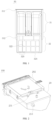
FIG. 1 is a schematic view of a planar structure of a dispenser according to some embodiments of the present disclosure. -
FIG. 2 is a schematic view of a perspective assembly structure of a detergent drawer assembly according to some embodiments of the present disclosure. -
FIG. 3 is a schematic view of a planar structure of a detergent drawer assembly according to some embodiments of the present disclosure. -
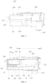
FIG. 4 is a schematic view of a partial sectional structure of a detergent drawer assembly according to some embodiments of the present disclosure. -
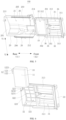
FIG. 5 is a schematic view of partial perspective disassembly of a detergent drawer assembly according to some embodiments of the present disclosure. -
FIG. 6 is a schematic view of another partial perspective disassembly of a detergent drawer assembly according to some embodiments of the present disclosure. -
FIG. 7 is a schematic view of a perspective structure of a filter of a detergent drawer assembly according to some embodiments of the present disclosure. -
FIG. 8 is a schematic view of a perspective structure of a filter of a detergent drawer assembly according to some embodiments of the present disclosure. -
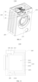
FIG. 9 is a schematic view of a perspective structure of a clothes treatment apparatus according to some embodiments of the present disclosure. -
FIG. 10 is a schematic view of a structure of a clothes treatment apparatus according to some embodiments of the present disclosure. - Embodiments of the present disclosure will be described in detail below with reference to examples thereof as illustrated in the accompanying drawings, throughout which same or similar elements, or elements having same or similar functions, are denoted by same or similar reference numerals. The embodiments described below with reference to the drawings are illustrative and are merely intended to explain, rather than limiting, the present disclosure.
- In the description of the present disclosure, it should be understood that the orientation or position relationship indicated by the terms, such as "thickness", "upper", "top", "bottom", "inner", and "outer", should be construed to refer to the orientation or the position relationship as shown in the drawings, and is only for the convenience of describing the present disclosure and simplifying the description, rather than indicating or implying that the associated device or element must have a specific orientation, or be constructed and operated in a specific orientation, and therefore cannot be understood as limitation of the present disclosure. In addition, terms "first" and "second" are only used for descriptive purposes, and cannot be understood as indicating or implying relative importance or implicitly indicating the number of the indicated technical features. Therefore, the features associated with "first" and "second" may explicitly or implicitly comprise at least one feature. In the description of the present disclosure, "a plurality of" means at least two, unless otherwise specifically defined.
- In the description of the present disclosure, it should be noted that, unless otherwise clearly specified and limited, terms "install", "connect", and "connect to" should be understood in a broad sense. For example, it may be a fixed connection, a detachable connection, or an integral connection; mechanical connection, electrical connection, or in communication with each other; direct connection or indirect connection through an intermediate; or internal communication of two components or the interaction relationship between two components.
- Referring to
FIG. 1 , an embodiment of the present disclosure provides adispenser 30. Thedispenser 30 comprises a dispensingarea 31 and afiltering area 32. Thefiltering area 32 is located at aside 312 of the dispensingarea 31. Thefiltering area 32 is provided with awater inlet area 320 for to-be-filtered washing water at anend 324 of thefiltering area 32. A part of a bottom 322 of thefiltering area 32 close to thewater inlet area 320 is higher than a part of the bottom 322 of thefiltering area 32 away from thewater inlet area 320. - In the
dispenser 30 according to the embodiments of the present disclosure, since the part of the bottom 322 of thefiltering area 32 close to thewater inlet area 320 is higher than the part of the bottom 322 of thefiltering area 32 away from thewater inlet area 320, to-be-filtered washing water flowing into thefiltering area 32 from thewater inlet area 320 can flow from high to low along thebottom 322 of thefiltering area 32 to the part of the bottom 322 of thefiltering area 32 away from thewater inlet area 320. Then, the washing water smoothly flows to the water outlet 212 (shown inFIG. 4 ), and drive the accumulated micro-particles to accumulate in a direction away from thewater inlet area 320, thereby smoothly realizing circulation flow and enhancing the service life of the filter 10 (shown inFIG. 4 ). Therefore, thefilter 10 can collect more micro-particles and reduce the number of times the user has to clean or replace thefilter 10. - The present disclosure is described in further detail below in conjunction with the accompanying drawings.
- Referring to
FIG. 2 to FIG. 4 , the present disclosure provides adetergent drawer assembly 100. Thedetergent drawer assembly 100 comprises adetergent drawer 20, thedispenser 30, and thefilter 10. Thefilter 10 is detachably mounted at thedispenser 30. Thedispenser 30 and thefilter 10 are drawably disposed in thedetergent drawer 20. - Referring to
FIG. 4 to FIG. 6 , in an exemplary embodiment of the present disclosure, thedetergent drawer 20 has acavity 21. Thedetergent drawer 20 has awater inlet 211, awater outlet 212, and a circulatingwater inlet 213 at a peripheral wall of thedetergent drawer 20. Each of thewater inlet 211, thewater outlet 212, and the circulatingwater inlet 213 is in communication with thecavity 21. That is, thewater inlet 211 is in communication with thecavity 21, thewater outlet 212 is in communication with thecavity 21, and the circulatingwater inlet 213 is in communication with thecavity 21. - Referring to
FIG. 4 , in some embodiments, the peripheral wall of thedetergent drawer 20 comprises asidewall 201, a top 202, and a bottom 203. In an embodiment, thewater inlet 211 is formed at the top 202. Thewater outlet 212 is formed at the bottom 203. The circulatingwater inlet 213 is formed at thesidewall 201. - Referring to
FIG. 5 , in some embodiments, thedetergent drawer 20 has anopening 214 through which thedispenser 30 is drawable. Thedispenser 30 is inserted into or pulled out from thecavity 21 through theopening 214. Referring toFIG. 5 and FIG. 6 , when detergent needs to be added, thedispenser 30 is pulled out from thecavity 21 to allow thedispenser 30 to be at least partially exposed outside thehousing 200, thereby facilitating the user to put the detergent into thedispenser 30. - Referring to
FIG. 4 , in an embodiment, thedetergent drawer 20 further comprises awater inlet tube 231. The top 202 comprises awater inlet chamber 232 in communication with thewater inlet 211. Thewater inlet tube 231 is connected to an external water source. After the user puts the detergent into thedispenser 30, thedispenser 30 is pushed back into thecavity 21, and water is injected into thewater inlet tube 231 from the external water source. The injected water flows to thewater inlet 211 after passing through thewater inlet chamber 232, and flows to thedispenser 30 in thecavity 21 from thewater inlet 211, to flush the detergent in thedispenser 30 to thewater outlet 212. The detergent-containing water flows into an external device from thewater outlet 212, and the external device may be washed with the detergent-containing water. The detergent-containing water in the external device can reflow into thedetergent drawer assembly 100 from the circulatingwater inlet 213 to form circulating water. - Referring to
FIG. 4 , in some embodiments, onewater outlet 212 is provided, and thewater outlet 212 is formed at the bottom 203 of thedetergent drawer 20 and close to theopening 214. In an exemplary embodiment of the present disclosure, thewater outlet 212 is located at a lowest position of the bottom 203 of thedetergent drawer 20. Therefore, both a cleaning water with the rinsed detergent after passing through thewater inlet 211 or the circulating water after passing through thefilter 10 can quickly flow to thewater outlet 212 at the lowest position, thereby improving the circulation efficiency and further improving the washing efficiency. - In other embodiments, the
water outlet 212 comprises at least two sub-water outlets. For example, thewater outlet 212 comprises two sub-water outlets, i.e., a main water outlet and an auxiliary water outlet (not shown in the figures). The main water outlet is the same as thewater outlet 212 in the above embodiments (shown inFIG. 4 ), and may be formed at the bottom 203 of thedetergent drawer 20 and close to theopening 214. The main water outlet may be located at the lowest position of the bottom 203 of thedetergent drawer 20. Therefore, both the cleaning water with the rinsed detergent after passing through thewater inlet 211 or the circulating water after passing through thefilter 10 can quickly flow to the main water outlet at the lowest position, thereby improving the circulation efficiency and further improving the washing efficiency. The auxiliary water outlet may further be formed at the bottom 203 of thedetergent drawer 20 and close to thefiltering area 32. A flow detection device is mounted at the auxiliary water outlet, and the auxiliary water outlet is in communication with the main water outlet via a tube located outside thedetergent drawer 20. The flow detection device is configured to monitor a flow rate of water falling from thefiltering area 32, thereby monitoring whether thefiltering area 32 is blocked. Once the blocking occurs, the flow detection device is configured to feedback to the user to remind the user to clean impurities in thefiltering area 32 in time. - The
dispenser 30 is drawably mounted in thecavity 21. When thedispenser 30 is mounted in thecavity 21, achannel 215 is formed between thedispenser 30 and thebottom 203 of thecavity 21. The circulating water in thedispenser 30 can flow into thechannel 215 and then flow to thewater outlet 212 through thechannel 215. - Referring to
FIG. 5 , in some embodiments, each of asidewall 205 and asidewall 206 at two sides of theopening 214 of thedetergent drawer 20 is provided with a slidingrail 26. Each of asidewall 301 and asidewall 302 of thedispenser 30 is provided with a slidingblock 36. Each of the slidingrails 26 cooperates with a corresponding one of the slidingblocks 36 to enable thedispenser 30 to slide relative to thedetergent drawer 20 in thecavity 21, to facilitate drawing of thedispenser 30. In other embodiments, each of thesidewall 205 and thesidewall 206 at the two sides of theopening 214 of thedetergent drawer 20 is provided with the sliding block, and each of thesidewall 301 and thesidewall 302 of thedispenser 30 is provided with the sliding rail, which is not limited herein. - In some embodiments, the
dispenser 30 comprises the dispensingarea 31 and thefiltering area 32 located at theside 312 of the dispensingarea 31. A top side of the dispensingarea 31 is open to receive the detergent, and a top side of thefiltering area 32 is open to receive thefilter 10. For example, in the embodiment shown inFIG. 5 , an end of the dispensingarea 31 facing theopening 214 is afront end 311, and the side at which thefiltering area 32 is located is arear end 312. The dispensingarea 31 is adjacent to thefiltering area 32. When thedispenser 30 is mounted in thecavity 21, the dispensingarea 31 corresponds to and is in communication with thewater inlet 211, and thefiltering area 32 is in communication with the circulatingwater inlet 213 and thewater outlet 212. - In an embodiment, the
dispenser 30 further comprises abaffle 35 provided between thefiltering area 32 and the dispensingarea 31. Thebaffle 35 is configured to separate thefiltering area 32 from the dispensingarea 31. When thedispenser 30 is located in thecavity 21, the dispensingarea 31 corresponds to and is in communication with thewater inlet 211, and thefiltering area 32 is in communication with the circulatingwater inlet 213 and thewater outlet 212. - Referring to
FIG. 4 andFIG. 6 , thefilter 10 is mounted in thefiltering area 32, and is configured to filter the circulating water flowing into thefiltering area 32 from the circulatingwater inlet 213. Water flows into the dispensingarea 31 from thewater inlet 211 and rinses the detergent in the dispensingarea 31 to thewater outlet 212. After the detergent-containing water flows into a washing cavity 2103 (shown inFIG. 10 ) to clean a to-be-cleaned object, the generated wastewater containing a large number of micro-particles flows into thefiltering area 32 from the circulatingwater inlet 213, is filtered by thefilter 10, and then flows back to thewashing cavity 2103 through thewater outlet 212. In this way, it can not only realize the recycling of water but also filter most of the lint and micro-particles in the water. In this way, a large number of micro-particles are prevented from being directly discharged into the environment along with the washing water, thereby reducing environmental pollution. The circulating water circulates from the circulatingwater inlet 213 into thedetergent drawer 20, and exits from thewater outlet 212 after being filtered by thefilter 10. In this way, after multiple filtrations, the micro-particles in the circulating water are successively intercepted by thefilter 10, allowing the micro-particles in the circulating water leaving thewater outlet 212 after each filtration to be reduced. Therefore, the micro-particles in the circulating water can be effectively filtered to reduce the pollution of the micro-particles to the environment. - In an exemplary embodiment of the present disclosure, referring to
FIG. 7 , thefilter 10 comprises aflexible filter bag 11 and a fixednozzle 12. Theflexible filter bag 11 has awater inlet 111 and a plurality of water outlet holes 112. The fixednozzle 12 is disposed at thewater inlet 111, and is configured to allow the circulating water to pass through to flow into thefilter bag 11 from thewater inlet 111. The plurality ofwater outlet hole 112 of theflexible filter bag 11 is configured to block at least part of the micro-particles in the circulating water and allow the filtered circulating water to pass therethrough. - The circulating water is water that flows into
filter 10 multiple times. For example, thefilter 10 is connected to an external element, and the circulating water circulates between thefilter 10 and the washing cavity 2103 (shown inFIG. 10 ). The circulating water is filtered once each time it flows through thefilter 10. As the number of filtrations increases, a microparticle content of the circulating water decreases. Non-circulating water may also be filtered by thefilter 10, which is not limited herein. - The
filter 10 in the embodiment shown inFIG. 7 and FIG. 8 only schematically shows a number, shape, and size of the water outlet holes 112. In other embodiments, the number and size of the water outlet holes 112 may be adjusted based on filtration requirements, which are not limited herein. For example, the number of the water outlet holes 112 may be 80 mesh, 100 mesh, 120 mesh, or the like, which is not limited herein. As shown inFIG. 7 , in an embodiment, the water outlet holes 112 are distributed throughout theflexible filter bag 11, allowing the water outlet efficiency to be high and allowing water to flow out in multiple directions. As shown inFIG. 8 , in another embodiment, the water outlet holes 112 are formed in a partial area of theflexible filter bag 11, to limit a position of the water outlet and an impact direction of the water flow. - The micro-particles comprise particles with smaller diameters such as microplastics, for example, plastic particles with a diameter smaller than 5 mm. The microparticles are difficult to decompose in nature, and are easy to enter a natural water cycle due to their small size. Therefore, discharging circulating water containing micro-particles into nature will bring greater pollution. The
filter 10 of the embodiments of the present disclosure can filter the micro-particles in the circulating water to reduce environmental pollution caused by the micro-particles. - When a rigid filter mesh structure is configured to filter micro-particles in a fluid, the micro-particles are easy to accumulate at a mesh of the filter, resulting in low filtration efficiency of the filter mesh structure. The
flexible filter bag 11 is a flexible structure. When the circulating water flows, theflexible filter bag 11 deforms, and a position of the water outlet holes 112 relative to the external element (the detergent drawer 20) is changed. Therefore, the micro-particles are not easy to accumulate at the fixed position of the external element, and allow the water to flow out more smoothly. - Referring to
FIG. 7 and 8 , in some embodiments, the fixednozzle 12 comprises awater inlet nozzle 121 and a fixingplate 122. Thewater inlet nozzle 121 is mounted at thewater inlet 111 and protrudes out of theflexible filter bag 11. The fixingplate 122 is arranged around thewater inlet nozzle 121, and is configured to be connected with the external element (i.e., the detergent drawer 20). - Referring to
FIG. 5 to FIG. 7 , the circulatingwater inlet 213 is formed at thesidewall 201 of thedetergent drawer 20 opposite to theopening 214 and protrudes out of thecavity 21. Referring toFIG. 4 ,FIG. 7, and FIG. 8 , in an example, thewater inlet nozzle 121 of the fixednozzle 12 extends into the circulatingwater inlet 213 to allow thewater inlet nozzle 121 to be in communication with the circulatingwater inlet 213. The circulating water flows into theflexible filter bag 11 through thewater inlet nozzle 121 and flows out from the water outlet holes 112. In another example, thewater inlet nozzle 121 of the fixednozzle 12 does not extend into the circulatingwater inlet 213, and the fixednozzle 12 and the circulatingwater inlet 213 only need to be engaged in alignment with each other to form a closed passage through which the water can flow. Therefore, thewater inlet nozzle 121 can be in communication with the circulatingwater inlet 213, and the circulating water flows into theflexible filter bag 11 through thewater inlet nozzle 121 and flows out from the water outlet holes 112. In another example, thewater inlet nozzle 121 of the fixednozzle 12 does not extend into the circulatingwater inlet 213, and is spaced apart from and opposite to the circulatingwater inlet 213. A pipeline may be provided for communication between thewater inlet nozzle 121 and the circulatingwater inlet 213. Therefore, the circulating water flows into theflexible filter bag 11 through thewater inlet nozzle 121 and flows out from the water outlet holes 112. In some embodiments, thefiltering area 32 comprises a throughhole 321 in communication with thechannel 215. The circulating water flowing from the water outlet holes 112 flows into thechannel 215 through the throughhole 321, to flow into thewater outlet 212 from thebottom 203 of thecavity 21. - Referring to
FIG. 5 to FIG. 7 , in some embodiments, thesidewall 324 of thefiltering area 32 has a mountinghole 323 corresponding to the circulatingwater inlet 213. The fixingplate 122 of the fixednozzle 12 is detachably mounted in the mountinghole 323, to allow thefilter 10 to be detachably mounted in thefiltering area 32. Thus, thefilter 10 containing the micro-particles can be easily removed. For example, when the number of the micro-particles in theflexible filter bag 11 is large, thefilter 10 is detached from thefiltering area 32. The micro-particles in thefilter 10 are removed and then remounted in thefiltering area 32, or anew filter 10 is replaced and mounted in thefiltering area 32, to remove the micro-particles in time and prevent the micro-particles from blocking the water outlet holes 112 and hindering the circulation of the circulating water. - In an embodiment, a sidewall 3231 of the mounting
hole 323 is provided with an engagement groove 3232. The fixingplate 122 can be inserted into or pulled out from the engagement groove 3232, to allow the fixingplate 122 to be detachably mounted in the mountinghole 323. An engagement structure of the fixingplate 122 and the engagement groove 3232 is simple to achieve a convenient disassembling operation. - In another embodiment, a
sidewall 1221 of the fixingplate 122 is provided with an engagement groove (not shown in the figures). The sidewall 3231 of the mountinghole 323 can be directly inserted into or pulled out from the engagement groove, to allow the fixingplate 122 to be detachably mounted in the mountinghole 323. In another exemplary embodiment of the present disclosure, the sidewall 3231 of the mountinghole 323 is provided with a protrusion (not shown in the figures), and a thickness of the protrusion is smaller than a thickness of the sidewall of the mountinghole 323. The protrusion can be inserted into or pulled out from the engagement groove, to allow the fixingplate 122 to be detachably mounted in the mountinghole 323. - In another embodiment, the sidewall 3231 of the mounting
hole 323 has a first thread (not shown in the figures), and the fixingplate 122 has a second thread (not shown in the figures). The first thread is engaged with the second thread to allow the fixingplate 122 to be detachably mounted in the mountinghole 323. The threaded engagement between the fixingplate 122 and the mountinghole 323 can make the connection between the fixingplate 122 and the mountinghole 323 more stable. - Referring to
FIG. 5 to FIG. 7 , in some embodiments, thefilter bag 11 is laid flat at the bottom 322 of thefiltering area 32 when the circulating water does not flow into thefilter bag 11. Thefilter bag 11 is filled with water and bulges to fill thefiltering area 32 when the circulating water flows into thefilter bag 11 through the circulatingwater inlet 213 and thewater inlet nozzle 121. As the circulating water continues to flow into thefilter bag 11, a water pressure is formed in the bulgedfilter bag 11. Even if part of the water outlet holes 112 are blocked, the circulating water can be pressed out from the blocked water outlet holes 112 under the action of the water pressure, allowing the circulating water to smoothly flow out of thefilter bag 11. - Referring to
FIG. 3 and FIG. 4 , in some embodiments, the peripheral wall of thedetergent drawer 20 further has ananti-blocking opening 204, and theanti-blocking opening 204 corresponds to and is in communication with thefiltering area 32. Theanti-blocking opening 204 is located higher than the circulatingwater inlet 213. Theanti-blocking opening 204 is configured to allow the circulating water to flow into thefiltering area 32, when the micro-particles in thefilter bag 11 are overloaded and the circulating water cannot flow into thefilter bag 11 from the circulatingwater inlet 213. - Referring to
FIG. 4 andFIG. 5 , in some embodiments, in a direction X1 from the dispensingarea 31 to thefiltering area 32, a part of the bottom 313 of the dispensingarea 31 close to thewater inlet 211 is higher than a part of the bottom 313 of the dispensingarea 31 away from thewater inlet 211. In this way, it is possible to facilitate the detergent injected at the part close to thewater inlet 211 to flow from high to low to the part away from thewater inlet 211. In one embodiment, adrain outlet 3131 is formed at the part of the bottom 313 away from thewater inlet 211, and is in communication with thechannel 215. The detergent injected from thewater inlet 211 can flow into thedrain outlet 3131 from high to low, flow into thechannel 215 from thedrain outlet 3131, and exit from thewater outlet 212. - In another embodiment, the
bottom 313 of the dispensingarea 31 is sealed, and the dispensingarea 31 is in communication with thewater outlet 212 through the throughhole 321 of the bottom 322 of thefiltering area 32. The dispensingarea 31 is in communication with thefiltering area 32. For example, referring toFIG. 5 , thedispenser 30 further comprises thebaffle 35 arranged between thefiltering area 32 and the dispensingarea 31, and thebaffle 35 has acommunication hole 351. The part of the bottom 313 of the dispensingarea 31 close to thewater inlet 211 is higher than a part of the bottom 313 of the dispensingarea 31 close to thebaffle 35. In this way, the detergent injected from thewater inlet 211 can flow from high to low to thecommunication hole 351 and reach thefiltering area 32 after passing through thecommunication hole 351. Referring toFIG. 4 , the circulating water of thefilter 10 flows into thechannel 215 through the throughhole 321 and exits through thewater outlet 212, thereby increasing the flow rate of the water flowing out of the dispensingarea 31. - When there is no circulating water in the
detergent drawer 20, the detergent in thechannel 215 can exit from thewater outlet 212, which is not limited herein. - In some embodiments, the
bottom 313 of the dispensingarea 31 is an inclined plane. A part of the inclined plane close to thewater inlet 211 is at a high position, and a part of the inclined plane away from thewater inlet 211 is at a low position. A surface of the inclined plane may be a flat surface or a curved surface, which is not limited herein. - For example, in the embodiment of
FIG. 4 andFIG. 5 , a side of the dispensingarea 31 facing theopening 214 is thefront end 311, and the side at which thefiltering area 32 is located is therear end 312. Thewater inlet 211 is formed at thefront end 311. In an embodiment, a direction from thefront end 311 to therear end 312 or a direction from therear end 312 to thefront end 311 is a length direction (X1/X2) of thedispenser 30. Accordingly, the two sides of theopening 214 form a width direction (Y1/Y2) of thedispenser 30. Thebottom 313 of the dispensingarea 31 is inclined in the length direction (X1/X2). In another embodiment, the direction from thefront end 311 to therear end 312 or the direction from therear end 312 to thefront end 311 is the width direction of thedispenser 30. Accordingly, the two sides of theopening 214 form the length direction of thedispenser 30. Thebottom 313 of the dispensingarea 31 is inclined in the width direction, which is not limited herein. - Referring to
FIG. 5 and FIG. 6 , in some embodiments, when thedispenser 30 is located in thecavity 21, a part of the bottom 322 of thefiltering area 32 close to the circulating water inlet 213 (or the mountinghole 323, as below) is higher than a part of the bottom 322 of thefiltering area 32 away from the circulatingwater inlet 213. Since thefilter bag 11 has flexibility, a part of thefilter bag 11 disposed in thefiltering area 32 close to the circulatingwater inlet 213 is higher than a part of thefilter bag 11 away from the circulatingwater inlet 213. In this way, it is convenient for the circulating water to flow from high to low to a position away from thewater inlet 211, and the existing micro-particles in thefilter 10 are rinsed and driven to gather at a position away from the circulatingwater inlet 213, to avoid accumulation near the circulatingwater inlet 213, thereby improving a space utilization ratio of thefilter 10. Referring toFIG. 5 , in an embodiment, the throughhole 321 in communication with thechannel 215 is formed at the part of the bottom 322 of thefiltering area 32 away from the circulatingwater inlet 213. The circulating water in thefilter bag 11 flows from high to low to the throughhole 321, and flows into thechannel 215 from the throughhole 321. - In some embodiments, the
bottom 322 of thefiltering area 32 is an inclined plane. A part of the inclined plane close to the circulatingwater inlet 213 is at a high position, and a part of the inclined plane away from the circulatingwater inlet 213 is at a low position. A surface of the inclined plane may be a flat surface or a curved surface, which is not limited herein. In an embodiment, thebottom 322 of thefiltering area 32 has the throughhole 321 only at the lower part of the bottom 322. In another embodiment, a plurality of throughholes 321 are formed at the bottom of thefiltering area 32, and throughholes 321 are formed at both the upper and lower parts of the bottom to increase the flow rate of the circulating water flowing into thechannel 215. - For example, in the embodiment of
FIG. 4 andFIG. 6 , the side of the dispensingarea 31 facing theopening 214 is thefront end 311, and the side of thefiltering area 32 is therear end 312. Thewater inlet 211 is formed at thefront end 311. In an embodiment, the direction from thefront end 311 to therear end 312 or the direction from therear end 312 to thefront end 311 is the length direction (X1/X2) of thedispenser 30. Accordingly, the two sides of theopening 214 form the width direction (Y1/Y2) of thedispenser 30. Thebottom 322 of thefiltering area 32 is inclined in the width direction (Y1/Y2). In another embodiment, the direction from thefront end 311 to therear end 312 or the direction from therear end 312 to thefront end 311 is the width direction of thedispenser 30. Accordingly, the two sides of theopening 214 form the length direction of thedispenser 30. Thebottom 322 of thefiltering area 32 is inclined in the length direction, which is not limited herein. - Referring to
FIG. 9 and FIG. 10 , the embodiments of the present disclosure provide aclothes treatment apparatus 1000. Theclothes treatment apparatus 1000 comprises ahousing 200, atub assembly 210 located in thehousing 200, a circulatingpump 220 located in thehousing 200, and adetergent drawer assembly 100 according to any one of the embodiments of the present disclosure. Referring toFIG. 4 andFIG. 8 , thedetergent drawer assembly 100 comprises thefilter 10 of the embodiments of the present disclosure. Thehousing 200 has a draw-outport 230, and thedetergent drawer assembly 100 is disposed in thehousing 200 and positioned at the draw-outport 230. Thetub assembly 210 comprises anouter tub 2101 and aninner tub 2102 rotatably disposed in theouter tub 2101. Theinner tub 2102 has awashing cavity 2103, and awater passage cavity 2104 is formed between theouter tub 2101 and theinner tub 2102. Thewater passage cavity 2104 is respectively in communication with thewashing cavity 2103 and the circulatingpump 220, to allow the circulating water in thewashing cavity 2103 to be introduced into the circulatingpump 220. Thewater outlet 212 is in communication with thewashing cavity 2103, and the circulatingpump 220 is connected to both thewater passage cavity 2104 and the circulatingwater inlet 213. In addition, theclothes treatment apparatus 1000 may further comprise acirculation tube 2201. One end of thecirculation tube 2201 is in communication with the circulatingwater inlet 213, and another end of thecirculation tube 2201 is in communication with the circulatingpump 220, to allow the circulatingpump 220 to be in communication with the circulatingwater inlet 213. In this way, the circulatingpump 220 can supply the circulating water into the circulatingwater inlet 213 through thecirculation tube 2201. - The
clothes treatment apparatus 1000 can be configured to wash to-be-washed objects, such as clothes and shoes. For example, theclothes treatment apparatus 1000 is a washing machine for washing clothes. Referring toFIG. 5 andFIG. 9 , the user loads the to-be-washed objects into thewashing cavity 2103 of theinner tub 2102 before washing, and then puts the detergent into thedispenser 30. Water is injected into thedetergent drawer assembly 100 through thewater inlet tube 231, and the water flowing into thedetergent drawer assembly 100 is mixed with the detergent and then flows into thewashing cavity 2103 through thewater outlet 212. During washing, theinner tub 2102 rotates relative to theouter tub 2101 to drive the to-be-washed objects and detergent-containing washing water in thewashing cavity 2103 to rotate for washing. In an embodiment, the washing water in theinner tub 2102 flows into thewater passage cavity 2104, and theouter tub 2101 discharges the washing water into the circulatingpump 220. The circulatingpump 220 pumps the washing water in thewater passage cavity 2104 to the circulatingwater inlet 213, to allow the washing water to reflow into thedetergent drawer assembly 100. Thus, the washing water circulates among thedetergent drawer assembly 100, thetub assembly 210, and the circulatingpump 220 to form the circulating water. - During the circulation of the circulating water, the micro-particles in the circulating water are filtered by the
filter 10 to prevent discharge of the circulating water containing the micro-particles to pollute the environment. Some impurities with a size larger than the size of the micro-particles, such as lint, hairballs, and paper scraps, can also be filtered by thefilter 10 to avoid impurities adhering to the washed objects, for example, to avoid paper scraps adhering to the surface of the washed clothes. - In summary, in the
detergent drawer assembly 100 and theclothes treatment apparatus 1000 of the embodiments of the present disclosure, theflexible filter bag 11 of thefilter 10 can filter the micro-particles in the circulating water, and theflexible filter bag 11 can deform to a certain extent with the flow of the circulating water, thereby changing the position of the water outlet holes 112 relative to the external element (i.e., the detergent drawer 20). Therefore, the micro-particles are not easy to accumulate in a fixed position of the external element (i.e., the detergent drawer 20), and the water can flow out more smoothly. - In the description of this specification, descriptions with reference to the terms, such as "some embodiments", "an example", and "for example", mean that specific features, structure, materials or characteristics described in conjunction with the embodiments or examples are comprised in at least one embodiment or example of the present disclosure. In this specification, the schematic representations of the above terms do not necessarily refer to the same embodiment or example. Moreover, the described specific features, structures, materials or characteristics may be combined in any one or more embodiments or examples in a suitable manner. Furthermore, different embodiments or examples and features of different embodiments or examples described in this specification may be combined and combined by those skilled in the art without contradiction.
- Any process or method described in a flowchart or described herein in other ways may be understood to comprise one or more modules, segments, or portions of codes of executable instructions for achieving specific logical functions or steps in the process. The scope of a preferred embodiment of the present disclosure comprises other implementations. A function may be performed not in a sequence shown or discussed, comprising a substantially simultaneous manner or a reverse sequence based on the function involved, which should be understood by those skilled in the art to which the embodiments of the present disclosure belong.
- Although embodiments of the present disclosure have been shown and described above, it should be understood that the above embodiments are merely exemplary, and cannot be construed as limitation of the present disclosure. For those skilled in the art, changes, alternatives, and modifications can be made to the above embodiments without departing from the scope of the present disclosure.
Claims (11)
- A dispenser, comprising:a dispensing area; anda filtering area located at a side of the dispensing area, the filtering area being provided with a water inlet area for to-be-filtered washing water at an end of the filtering area, and a part of a bottom of the filtering area close to the water inlet area being higher than a part of the bottom of the filtering area away from the water inlet area.
- The dispenser according to claim 1, wherein the bottom of the filtering area is inclined downwardly in a direction from close to the water inlet area to away from the water inlet area.
- The dispenser according to claim 1, wherein a bottom of the dispensing area is inclined downwardly in a direction from the dispensing area to the filtering area.
- The dispenser according to claim 1, wherein the dispensing area has a sealed bottom;the bottom of the filtering area has a through hole; anda baffle is provided between the dispensing area and the filtering area, the baffle having a communication hole, and the dispensing area being in communication with the filtering area through the communication hole.
- A detergent drawer assembly, comprising:a detergent drawer having a cavity, the detergent drawer having a water inlet, a water outlet, and a circulating water inlet at a peripheral wall of the detergent drawer, and each of the water inlet, the water outlet, and the circulating water inlet being in communication with the cavity;a dispenser according to any one of claims 1 to 4, the dispenser being mounted and drawable in the cavity, a dispensing area corresponding to and being in communication with the water inlet, and a filtering area being in communication with the circulating water inlet and the water outlet; anda filter mounted in the filtering area and configured to filter circulating water flowing into the filtering area from the circulating water inlet.
- The detergent drawer assembly according to claim 5, wherein the detergent drawer has an opening through which the dispenser is drawable; and
the circulating water inlet is formed at a side wall of the detergent drawer opposite to the opening. - The detergent drawer assembly according to claim 6, wherein the peripheral wall of the detergent drawer further has an anti-blocking opening in communication with the cavity, the anti-blocking opening being higher than the circulating water inlet and being configured to allow the circulating water to flow into the filtering area.
- The detergent drawer assembly according to claim 6, wherein the water outlet comprises at least two sub-water outlets, a flow detection device being disposed on at least one of the at least two sub-water outlets.
- The detergent drawer assembly according to claim 5, wherein the filter comprises a flexible filter bag and a fixed nozzle provided at an inlet of the filter bag; and
the filter is detachably mounted in the filtering area by the fixed nozzle. - The detergent drawer assembly according to claim 9, wherein the fixed nozzle is engaged with the circulating water inlet, the circulating water flowing into the filter bag through the fixed nozzle; and
the filter bag has a plurality of water outlet holes, the plurality of water outlet holes being configured to allow filtered circulating water to flow to the water outlet through the plurality of water outlet holes. - A clothes treatment apparatus, comprising:a housing;a tub assembly located within the housing, the tub assembly having a washing cavity;a detergent drawer assembly according to any one of claims 5 to 10, a water outlet of the detergent drawer assembly being in communication with the washing cavity; anda circulating pump located within the housing, the circulating pump being connected to both the washing cavity and a circulating water inlet.
Applications Claiming Priority (3)
| Application Number | Priority Date | Filing Date | Title |
|---|---|---|---|
| CN202210730928.XA CN117306211A (en) | 2022-06-24 | 2022-06-24 | Dispensers, detergent box components and laundry treatment equipment |
| CN202221614534.XU CN217678200U (en) | 2022-06-24 | 2022-06-24 | Dispenser, detergent box assembly and clothes treatment equipment |
| PCT/CN2023/098892 WO2023246511A1 (en) | 2022-06-24 | 2023-06-07 | Dispenser, detergent drawer assembly, and clothes treatment apparatus |
Publications (2)
| Publication Number | Publication Date |
|---|---|
| EP4534753A1 true EP4534753A1 (en) | 2025-04-09 |
| EP4534753A4 EP4534753A4 (en) | 2025-10-01 |
Family
ID=89379142
Family Applications (1)
| Application Number | Title | Priority Date | Filing Date |
|---|---|---|---|
| EP23826160.6A Pending EP4534753A4 (en) | 2022-06-24 | 2023-06-07 | DISPENSER, DETERGENT DRAWER ARRANGEMENT AND LAUNDRY TREATMENT DEVICE |
Country Status (2)
| Country | Link |
|---|---|
| EP (1) | EP4534753A4 (en) |
| WO (1) | WO2023246511A1 (en) |
Families Citing this family (2)
| Publication number | Priority date | Publication date | Assignee | Title |
|---|---|---|---|---|
| CN117306207B (en) * | 2022-06-24 | 2025-11-28 | 无锡小天鹅电器有限公司 | Detergent box assembly and clothes treatment equipment |
| CN117306208B (en) * | 2022-06-24 | 2025-11-28 | 无锡小天鹅电器有限公司 | Distributor component, detergent box assembly and clothes treatment equipment |
Family Cites Families (10)
| Publication number | Priority date | Publication date | Assignee | Title |
|---|---|---|---|---|
| DE1585660A1 (en) * | 1966-08-01 | 1971-06-16 | Cge Co Generale Di Elettricita | Detergent addition container and filter for the washing solution cycle in washing machines |
| US4081975A (en) * | 1977-04-22 | 1978-04-04 | General Motors Corporation | Clothes washer with centerpost mounted lint filter bag |
| JPH0994383A (en) * | 1995-09-29 | 1997-04-08 | Sharp Corp | Washing machine |
| CN2830467Y (en) * | 2005-07-29 | 2006-10-25 | 海尔集团公司 | Washing machine |
| JP6936593B2 (en) * | 2017-03-06 | 2021-09-15 | 東芝ライフスタイル株式会社 | Washing machine |
| PL3983599T3 (en) * | 2019-06-14 | 2025-04-07 | Arçelik Anonim Sirketi | A washing machine comprising a filtering member |
| TR201921414A2 (en) * | 2019-12-25 | 2021-07-26 | Arçeli̇k Anoni̇m Şi̇rketi̇ | A washing machine with a filter |
| CN215856820U (en) * | 2021-06-21 | 2022-02-18 | 无锡小天鹅电器有限公司 | Detergent box assembly and washing equipment |
| CN217459966U (en) * | 2022-06-24 | 2022-09-20 | 无锡小天鹅电器有限公司 | Detergent box assembly and clothes treatment equipment |
| CN217678200U (en) * | 2022-06-24 | 2022-10-28 | 无锡小天鹅电器有限公司 | Dispenser, detergent box assembly and clothes treatment equipment |
-
2023
- 2023-06-07 WO PCT/CN2023/098892 patent/WO2023246511A1/en not_active Ceased
- 2023-06-07 EP EP23826160.6A patent/EP4534753A4/en active Pending
Also Published As
| Publication number | Publication date |
|---|---|
| WO2023246511A1 (en) | 2023-12-28 |
| EP4534753A4 (en) | 2025-10-01 |
Similar Documents
| Publication | Publication Date | Title |
|---|---|---|
| CN217678200U (en) | Dispenser, detergent box assembly and clothes treatment equipment | |
| CN217459966U (en) | Detergent box assembly and clothes treatment equipment | |
| KR101375715B1 (en) | Detergent supply apparatus and washing machine having the same | |
| US20110197933A1 (en) | Dishwasher | |
| WO2023246511A1 (en) | Dispenser, detergent drawer assembly, and clothes treatment apparatus | |
| CN108514395A (en) | Dish-washing machine and its filtration system | |
| EP4560066A1 (en) | Filtering module, filtering module control method, and washing equipment | |
| CN217869597U (en) | Filter, dispensing part, detergent box assembly and clothes treatment equipment | |
| CN217869589U (en) | Dispenser part, detergent box assembly and clothes treatment equipment | |
| CN218492048U (en) | Filtering module | |
| CN111809373A (en) | A clothing treatment device | |
| CN211199787U (en) | Circulation drainage assembly of clothes treatment equipment and clothes treatment equipment | |
| CN117306208B (en) | Distributor component, detergent box assembly and clothes treatment equipment | |
| CN117306207B (en) | Detergent box assembly and clothes treatment equipment | |
| CN114293348B (en) | A detergent intelligent dispensing ink cartridge | |
| WO2023020183A1 (en) | Addition module and clothing treatment apparatus | |
| CN215628836U (en) | Thread scrap filtering device and washing machine | |
| CN117306211A (en) | Dispensers, detergent box components and laundry treatment equipment | |
| CN210684235U (en) | Automatic feeding system for washing machine and washing machine | |
| CN117306210A (en) | Filters, dispensing components, detergent box components and laundry treatment equipment | |
| CN215704348U (en) | Screw squeezer extrusion structure | |
| CN216640002U (en) | Intelligent detergent putting ink box | |
| CN113718489A (en) | Additive feeding module and clothes treatment device | |
| EP4644602A1 (en) | Washing machine, and filter device for washing machine | |
| EP4640939A1 (en) | Washing machine and filter device for washing machine |
Legal Events
| Date | Code | Title | Description |
|---|---|---|---|
| STAA | Information on the status of an ep patent application or granted ep patent |
Free format text: STATUS: THE INTERNATIONAL PUBLICATION HAS BEEN MADE |
|
| PUAI | Public reference made under article 153(3) epc to a published international application that has entered the european phase |
Free format text: ORIGINAL CODE: 0009012 |
|
| STAA | Information on the status of an ep patent application or granted ep patent |
Free format text: STATUS: REQUEST FOR EXAMINATION WAS MADE |
|
| 17P | Request for examination filed |
Effective date: 20250106 |
|
| AK | Designated contracting states |
Kind code of ref document: A1 Designated state(s): AL AT BE BG CH CY CZ DE DK EE ES FI FR GB GR HR HU IE IS IT LI LT LU LV MC ME MK MT NL NO PL PT RO RS SE SI SK SM TR |
|
| A4 | Supplementary search report drawn up and despatched |
Effective date: 20250903 |
|
| DAV | Request for validation of the european patent (deleted) | ||
| DAX | Request for extension of the european patent (deleted) | ||
| RIC1 | Information provided on ipc code assigned before grant |
Ipc: D06F 39/10 20060101AFI20250828BHEP Ipc: D06F 39/02 20060101ALI20250828BHEP Ipc: D06F 39/08 20060101ALI20250828BHEP |