EP4534734A1 - Control device for hydrogen production apparatuses, hydrogen production facility, method for controlling hydrogen production apparatus, and control program for hydrogen production apparatuses - Google Patents
Control device for hydrogen production apparatuses, hydrogen production facility, method for controlling hydrogen production apparatus, and control program for hydrogen production apparatuses Download PDFInfo
- Publication number
- EP4534734A1 EP4534734A1 EP23839494.4A EP23839494A EP4534734A1 EP 4534734 A1 EP4534734 A1 EP 4534734A1 EP 23839494 A EP23839494 A EP 23839494A EP 4534734 A1 EP4534734 A1 EP 4534734A1
- Authority
- EP
- European Patent Office
- Prior art keywords
- hydrogen production
- production apparatus
- time
- hydrogen
- pressure
- Prior art date
- Legal status (The legal status is an assumption and is not a legal conclusion. Google has not performed a legal analysis and makes no representation as to the accuracy of the status listed.)
- Pending
Links
Images




Classifications
-
- C—CHEMISTRY; METALLURGY
- C25—ELECTROLYTIC OR ELECTROPHORETIC PROCESSES; APPARATUS THEREFOR
- C25B—ELECTROLYTIC OR ELECTROPHORETIC PROCESSES FOR THE PRODUCTION OF COMPOUNDS OR NON-METALS; APPARATUS THEREFOR
- C25B1/00—Electrolytic production of inorganic compounds or non-metals
- C25B1/01—Products
- C25B1/02—Hydrogen or oxygen
- C25B1/04—Hydrogen or oxygen by electrolysis of water
-
- C—CHEMISTRY; METALLURGY
- C25—ELECTROLYTIC OR ELECTROPHORETIC PROCESSES; APPARATUS THEREFOR
- C25B—ELECTROLYTIC OR ELECTROPHORETIC PROCESSES FOR THE PRODUCTION OF COMPOUNDS OR NON-METALS; APPARATUS THEREFOR
- C25B15/00—Operating or servicing cells
- C25B15/02—Process control or regulation
-
- C—CHEMISTRY; METALLURGY
- C25—ELECTROLYTIC OR ELECTROPHORETIC PROCESSES; APPARATUS THEREFOR
- C25B—ELECTROLYTIC OR ELECTROPHORETIC PROCESSES FOR THE PRODUCTION OF COMPOUNDS OR NON-METALS; APPARATUS THEREFOR
- C25B15/00—Operating or servicing cells
- C25B15/02—Process control or regulation
- C25B15/023—Measuring, analysing or testing during electrolytic production
-
- C—CHEMISTRY; METALLURGY
- C25—ELECTROLYTIC OR ELECTROPHORETIC PROCESSES; APPARATUS THEREFOR
- C25B—ELECTROLYTIC OR ELECTROPHORETIC PROCESSES FOR THE PRODUCTION OF COMPOUNDS OR NON-METALS; APPARATUS THEREFOR
- C25B15/00—Operating or servicing cells
- C25B15/08—Supplying or removing reactants or electrolytes; Regeneration of electrolytes
-
- C—CHEMISTRY; METALLURGY
- C25—ELECTROLYTIC OR ELECTROPHORETIC PROCESSES; APPARATUS THEREFOR
- C25B—ELECTROLYTIC OR ELECTROPHORETIC PROCESSES FOR THE PRODUCTION OF COMPOUNDS OR NON-METALS; APPARATUS THEREFOR
- C25B15/00—Operating or servicing cells
- C25B15/08—Supplying or removing reactants or electrolytes; Regeneration of electrolytes
- C25B15/083—Separating products
-
- H—ELECTRICITY
- H01—ELECTRIC ELEMENTS
- H01M—PROCESSES OR MEANS, e.g. BATTERIES, FOR THE DIRECT CONVERSION OF CHEMICAL ENERGY INTO ELECTRICAL ENERGY
- H01M8/00—Fuel cells; Manufacture thereof
- H01M8/06—Combination of fuel cells with means for production of reactants or for treatment of residues
- H01M8/0606—Combination of fuel cells with means for production of reactants or for treatment of residues with means for production of gaseous reactants
- H01M8/0656—Combination of fuel cells with means for production of reactants or for treatment of residues with means for production of gaseous reactants by electrochemical means
-
- Y—GENERAL TAGGING OF NEW TECHNOLOGICAL DEVELOPMENTS; GENERAL TAGGING OF CROSS-SECTIONAL TECHNOLOGIES SPANNING OVER SEVERAL SECTIONS OF THE IPC; TECHNICAL SUBJECTS COVERED BY FORMER USPC CROSS-REFERENCE ART COLLECTIONS [XRACs] AND DIGESTS
- Y02—TECHNOLOGIES OR APPLICATIONS FOR MITIGATION OR ADAPTATION AGAINST CLIMATE CHANGE
- Y02E—REDUCTION OF GREENHOUSE GAS [GHG] EMISSIONS, RELATED TO ENERGY GENERATION, TRANSMISSION OR DISTRIBUTION
- Y02E60/00—Enabling technologies; Technologies with a potential or indirect contribution to GHG emissions mitigation
- Y02E60/30—Hydrogen technology
- Y02E60/36—Hydrogen production from non-carbon containing sources, e.g. by water electrolysis
Definitions
- Patent Document 1 discloses a system for producing hydrogen by electrolyzing water in a water electrolyzer provided with a solid electrolyte membrane.
- Patent Document 1 JP 2002-129372 A
- an object of at least one embodiment of the present invention is to provide a control device for a hydrogen production apparatus, a hydrogen production facility, a control method for a hydrogen production apparatus, and a control program for a hydrogen production apparatus by which the hydrogen production apparatus can efficiently operate while appropriately supplying hydrogen.
- a control device for a hydrogen production apparatus, a hydrogen production facility, a control method for a hydrogen production apparatus, and a control program for a hydrogen production apparatus by which the hydrogen production apparatus can efficiently operate while appropriately supplying hydrogen are provided.
- FIG. 1 and FIG. 2 are schematic diagrams of a hydrogen production facility to which a control device according to an embodiment is applied.
- a hydrogen production facility 100 includes a hydrogen production apparatus 10 configured to produce hydrogen, a storing unit 30 for storing the hydrogen produced by the hydrogen production apparatus 10, and a control device 50 for controlling the operation of the hydrogen production apparatus 10.
- Gaseous hydrogen is stored in the storing unit 30.
- the hydrogen stored in the storing unit 30 may be supplied to a hydrogen consuming facility 40.
- the storing unit 30 may have a feature suitable for supplying the hydrogen to the hydrogen consuming facility 40.
- the storing unit 30 may include, for example, a storage header (header tank).
- the storing unit 30 may be provided with a pressure sensor 60 configured to measure a pressure of the storing unit 30.
- the pressure sensor 60 may be electrically connected to the control device 50, and a signal indicating a measurement result by the pressure sensor 60 may be transmitted to the control device 50.
- the hydrogen consuming facility 40 is not particularly limited.
- the hydrogen consuming facility 40 may include, for example, a hydrogen combustion facility configured to burn hydrogen (e.g., a gas turbine facility or an iron manufacturing facility), a hydrogen liquefaction facility configured to liquefy hydrogen, a facility for generating electricity by a chemical reaction using hydrogen as a fuel (e.g., a power generation facility including a fuel cell such as a solid oxide fuel cell (SOFC)), a facility for producing fuel using hydrogen as a feedstock (e.g., a fuel synthesis facility), or a hydrogen gas station configured to supply hydrogen to a device.
- a hydrogen combustion facility configured to burn hydrogen
- a hydrogen liquefaction facility configured to liquefy hydrogen
- a facility for generating electricity by a chemical reaction using hydrogen as a fuel e.g., a power generation facility including a fuel cell such as a solid oxide fuel cell (SOFC)
- SOFC solid oxide fuel cell
- a feedstock e.g., a fuel
- the hydrogen production apparatus 10 may include a water electrolyzer configured to produce hydrogen by electrolysis of water.
- the type of water electrolyzer is not limited.
- the water electrolyzer may be, for example, an alkaline water electrolyzer, a polymer electrolyte membrane (PEM) water electrolyzer, an anion exchange membrane (AEM) water electrolyzer, or a solid oxide electrolysis cell (SOEC) water electrolyzer.
- the hydrogen production apparatus 10 may include a reformer configured to produce hydrogen by reforming a fossil fuel or the like, a plant in which hydrogen is secondarily generated, or the like.
- the hydrogen production apparatus 10 illustrated in FIG. 2 includes a water electrolyzer including an electrolytic tank 12 for electrolyzing water.
- the water electrolyzer including the electrolytic tank 12 is supplied with water via a water supply line (not illustrated).
- the water supply line may be configured to supply water to, for example, a gas-liquid separator 14 or 20 to be described below.
- the water in the electrolytic tank 12 is electrolyzed by applying a voltage between a pair of electrodes provided in the electrolytic tank 12 to produce hydrogen on the cathode side and oxygen on the anode side.
- Water in which an electrolyte is dissolved may be supplied into the electrolytic tank 12.
- the electrolyte may be an alkaline substance such as potassium hydroxide (KOH).
- the oxygen gas generated on the anode side is guided to the gas-liquid separator 20 via an anode-side line 22 in a state of containing water (electrolyte solution or the like).
- the oxygen gas containing water is separated into oxygen gas and water.
- the oxygen gas separated by the gas-liquid separator 20 is discharged from the gas-liquid separator 20 via an oxygen gas line 21.
- the oxygen gas discharged from the gas-liquid separator 20 may be supplied to an oxygen consuming facility or may be discharged to the outside.
- the water separated by the gas-liquid separator 20 is returned to the electrolytic tank 12 via a return line 24.
- the hydrogen production apparatus 10 may be provided with a pressure sensor 64 configured to measure a pressure of the gas-liquid separator 14 or 20 to which the hydrogen or the oxygen from the electrolytic tank 12 is guided.
- the pressure sensor 64 is configured to measure the pressure of the gas-liquid separator 14.
- the pressure sensor 64 may be configured to measure a pressure of the gas-liquid separator 20.
- the hydrogen production apparatus 10 may be provided with a temperature sensor 62 configured to measure a temperature of water (electrolyte solution or the like) in the hydrogen production apparatus 10.
- the temperature sensor 62 is configured to measure the temperature of the water in the cathode-side line 16.
- the temperature sensor 62 may be configured to measure the temperature of the water in the return line 18, the anode-side line 22, or the return line 24.
- the pressure sensor 64 and the temperature sensor 62 may be electrically connected to the control device 50, and signals indicating measurement results by the pressure sensor 64 and the temperature sensor 62 may be transmitted to the control device 50.
- the estimated reaching time calculation unit 52 is configured to calculate an estimated reaching time for the pressure of the storing unit 30 to reach a specified value with respect to a current time point on the basis of a change rate of the pressure of the storing unit 30.
- the change rate of the pressure of the storing unit 30 may be calculated on the basis of measured values of the pressure of the storing unit 30 acquired by the pressure sensor 60 at a plurality of time points.
- the start-up time acquisition unit 54 is configured to acquire a start-up time of the hydrogen production apparatus 10 (a time required to start up the hydrogen production apparatus 10) corresponding to the state of the hydrogen production apparatus 10.
- the start-up time acquisition unit 54 may acquire, on the basis of a state of the hydrogen production apparatus 10 at a present time point, a start-up time corresponding to the state on the basis of information indicating a correspondence relationship between the state of the hydrogen production apparatus 10 and the start-up time of the hydrogen production apparatus 10 which is stored in the storage unit 58 to be described below.
- the start-up time acquisition unit 54 may calculate a start-up time of the hydrogen production apparatus 10 on the basis of the temperature of the water in the electrolytic tank 12 and the pressure of the gas-liquid separator 14.
- the storage unit 58 is configured to store the information indicating a correspondence relationship between the state of the hydrogen production apparatus 10 and the start-up time of the hydrogen production apparatus 10.
- the storage unit 58 is configured to store the preset specified start-up time of the hydrogen production apparatus 10.
- the state of the hydrogen production apparatus 10 described above may be one or more of a time elapsed from the end of a previous operation of the hydrogen production apparatus 10, a temperature of a component device of the hydrogen production apparatus 10, a pressure of a component device of the hydrogen production apparatus 10, and a temperature of the water (electrolyte solution or the like) in the electrolytic tank. It is conceivable that when the state of the hydrogen production apparatus 10 varies, the start-up time of the hydrogen production apparatus 10 also varies.
- the storage unit 58 may store a plurality of states of the hydrogen production apparatus 10 and a plurality of start-up times respectively corresponding to the plurality of states. The correspondence relationship between the state of the hydrogen production apparatus 10 and the start-up time of the hydrogen production apparatus 10 may be acquired in advance by operating the hydrogen production apparatus 10 in advance.
- the control device 50 includes a computer including a processor (CPU or the like), a main storage device (a memory device; RAM or the like), an auxiliary storage device, an interface, and the like.
- the control device 50 is configured to receive signals from the pressure sensor 60, the temperature sensor 62, and/or the pressure sensor 64.
- the processor is configured to process the signals received in this manner.
- the processor is configured to process programs loaded in the main storage device. This achieves the functions of the estimated reaching time calculation unit 52, the start-up time acquisition unit 54, and the determination unit 56 described above.
- the storage unit 58 described above may include the main storage device or the auxiliary storage device of the computer constituting the control device 50.
- the processing contents of the control device 50 are implemented as programs to be executed by the processor.
- the programs may be stored in, for example, the auxiliary storage device.
- the programs are loaded in the main storage device.
- the processor is configured to read the programs from the main storage device and execute instructions included in the programs.
- a control method for a hydrogen production apparatus will be described.
- a case in which the above-described hydrogen production apparatus 10 is controlled using the above-described control device 50 will be described.
- a control method for a hydrogen production apparatus may be executed using another device, or a part or all of the procedure described below may be manually performed.
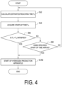
- FIG. 4 is a flowchart of a control method for a hydrogen production apparatus according to an embodiment.
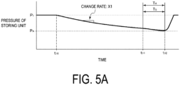
- FIG. 5A , FIG. 5B , and FIG. 6 are graphs each showing temporal change in pressure of a storing unit when a control method for a hydrogen production apparatus according to an embodiment is applied.
- the method according to the flowchart of FIG. 4 is started in a state where the hydrogen production apparatus 10 is stopped.
- the estimated reaching time calculation unit 52 calculates an estimated reaching time T A for the pressure of the storing unit 30 to reach a specified value P A on the basis of a change rate of the pressure of the storing unit 30 (S2).
- the change rate (decrease rate) of the pressure of the storing unit 30 during the stop of the hydrogen production apparatus 10 indicates an amount of hydrogen supplied from the storing unit 30 to the hydrogen consuming facility 40 or a hydrogen consumption rate in the hydrogen consuming facility 40.
- the specified value P A is the pressure of the storing unit 30 that should be maintained to appropriately supply hydrogen from the storing unit 30 to the hydrogen consuming facility 40.
- the change rate of the pressure of the storing unit 30 can be calculated, for example, by dividing a difference between pressures of the storing unit 30 at two time points different from each other by a length between the two time points.
- the pressure of the storing unit 30 can be acquired as a measured value by the pressure sensor 60.
- the pressure of the storing unit 30 decreases in association with the supply of hydrogen from the storing unit 30 to the hydrogen consuming facility 40, and the change rate of the pressure of the storing unit 30 is X1 in the examples illustrated in FIG. 5A and FIG. 6 and is X2 in the example illustrated in FIG. 5B .
- a start-up procedure of the hydrogen production apparatus is generally as follows. First, nitrogen gas is supplied to the gas-liquid separators 14 and 20 to increase the pressure, and then the nitrogen gas is discharged. By repeating this operation several times, the gas-liquid separators 14 and 20 are purged with the nitrogen gas. Next, a voltage is applied to the electrodes of the electrolytic tank 12 to start electrolysis of water. This starts the production of hydrogen, increases the pressure of the gas-liquid separators 14 and 20 and the like, and increases the temperature of the water. Then, the procedure waits until the pressure of the gas-liquid separator 14 or 20 rises to a predetermined value.
- the procedure waits until the purity of the produced hydrogen increases.
- Other devices for example, a dehumidifier for dehumidifying the hydrogen gas from the separator, a compressor for compressing the produced hydrogen gas, and the like
- a dehumidifier for dehumidifying the hydrogen gas from the separator for example, a dehumidifier for dehumidifying the hydrogen gas from the separator, a compressor for compressing the produced hydrogen gas, and the like
- the hydrogen production apparatus 10 including the water electrolyzer is started up.
- the start-up time T S may be calculated on the basis of the temperature of the water in the water electrolyzer (the temperature of the electrolyte solution; that is, a temperature measured by the temperature sensor 62) and the pressure of the gas-liquid separator 14 or 20 (that is, a pressure measured by the pressure sensor 64).
- a correlation between the temperature of the water in the water electrolyzer (the temperature of the electrolyte solution) and the start-up time T S and between the pressure of the gas-liquid separator 14 or 20 and the start-up time T S (a function or the like indicating the correlation) may be acquired in advance by a test run or the like and stored in the storage unit 58.
- the start-up time acquisition unit 54 may acquire the correlation from the storage unit 58 and calculate the start-up time T S from the correlation using a measured value of the temperature of the water in the water electrolyzer (the temperature of the electrolyte solution) and a measured value of the pressure of the gas-liquid separator 14 or 20.
- the temperature of the water in the water electrolyzer can be acquired as a measured value by the temperature sensor 62.
- the pressure of the gas-liquid separator 14 or 20 can be acquired as a measured value by the pressure sensor 64.
- step S4 the start-up time T S corresponding to the current state of the hydrogen production apparatus 10 may be acquired on the basis of information indicating a correspondence relationship between the state of the hydrogen production apparatus 10 and the start-up time T S .
- the correspondence relationship between the state of the hydrogen production apparatus 10 and the start-up time T S may be acquired in advance from measured values or the like during past operations of the hydrogen production apparatus 10, and information indicating the correspondence relationship may be stored in advance in the storage unit 58.
- the start-up time acquisition unit 54 may acquire the above-described information indicating the correspondence relationship from the storage unit 58 and acquire the start-up time T S corresponding to a current state of the hydrogen production apparatus 10 from the correspondence relationship.
- the current state of the hydrogen production apparatus 10 may be acquired from a sensor (for example, the temperature sensor 62) provided at the hydrogen production apparatus 10.
- the start-up time T S of the hydrogen production apparatus 10 is equal to or shorter than the estimated reaching time T A (No in step S6 and No in step S8) during a period from times t10 to t11 in FIG. 5A and during a period from times t20 to t21 in FIG. 5B , and thus the hydrogen production apparatus 10 is not started up. Then, the start-up time T S of the hydrogen production apparatus 10 is longer than the estimated reaching time T A (Yes in step S6) after a time t11 in FIG. 5A and after a time t21 in FIG.
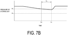
- FIG. 7A and FIG. 7B is a graph showing an example of a temporal change in the pressure of the storing unit when the on-off operation of the hydrogen production apparatus is performed on the basis of the pressure of the storing unit.
- T S represents a time required to start up the hydrogen production apparatus.
- the pressure of the storing unit is not lowered so much at the completion of the start-up of the hydrogen production apparatus (i.e., at the start of hydrogen production; a time t51 in FIG. 7B ), and thus the amount of hydrogen that can be produced per one operation (per one start-up) of the hydrogen production apparatus (the rise in the pressure of the storing unit) decreases, and the operation efficiency of the hydrogen production apparatus decreases.
- a time point at which the start-up time T S of the hydrogen production apparatus 10 becomes longer than the estimated reaching time T A is determined as a start-up timing. This can determine, in accordance with the consumption rate of hydrogen, a start-up timing as late as possible to the extent that the start-up of the hydrogen production apparatus 10 can be completed before the pressure of the storing unit 30 becomes lower than the specified value P A . As a result, the appropriate supply of hydrogen and the efficient operation of the hydrogen production apparatus 10 can be easily achieved in a compatible manner.
- a start-up timing of the hydrogen production apparatus 10 is determined on the basis of a comparison between the above-described estimated reaching time T A and the above-described start-up time T S and the preset specified start-up time t A . This can start up the hydrogen production apparatus 10 at a start-up timing corresponding to the consumption rate of hydrogen or at a preset appropriate start-up timing. As a result, the appropriate supply of hydrogen and the efficient operation of the hydrogen production apparatus can be easily achieved in a compatible manner.
- the specified start-up time t A is determined as a start-up timing. This can start up, even when the consumption rate of hydrogen is relatively low, the hydrogen production apparatus 10 at an appropriate timing and efficiently operate the hydrogen production apparatus 10. For example, by setting the specified start-up time described above at night during which an electric power load is low or during a time zone in which there is a surplus in electric power generated by regenerative energy, hydrogen can be efficiently produced by effectively using surplus electric power or the like.
- the storing unit 30 needs to have a volume for covering all the maximum consumption, and thus a facility cost and an installation space increase.
- the volume of the storing unit 30 can be reduced. Accordingly, the increase in a facility cost and an installation space can be suppressed.
- the change rate of the pressure of the storing unit indicates a rate at which the hydrogen stored in the storing unit is consumed.
- the start-up timing of the hydrogen production apparatus is determined on the basis of a comparison between the estimated reaching time calculated on the basis of the change rate of the pressure of the storing unit and the start-up time of the hydrogen production apparatus corresponding to the state of the hydrogen production apparatus.
- the start-up timing of the hydrogen production apparatus can be determined in accordance with the consumption rate of hydrogen. This can achieve the appropriate supply of hydrogen and the efficient operation of the hydrogen production apparatus in a compatible manner.
- the determination unit is configured to determine, as the start-up timing, a time point at which the start-up time becomes longer than the estimated reaching time.
- the determination unit is configured to determine the start-up timing on the basis of a comparison between the above-described estimated reaching time and the above-described start-up time and a specified start-up time preset (t A ).
- the start-up timing of the hydrogen production apparatus is determined on the basis of the comparison between the above-described estimated reaching time and the above-described start-up time and the preset specified start-up time. Accordingly, the hydrogen production apparatus can be started up at a start-up timing corresponding to the consumption rate of hydrogen or at a preset appropriate start-up timing. As a result, the appropriate supply of hydrogen and the efficient operation of the hydrogen production apparatus can be easily achieved in a compatible manner.
- the determination unit is configured to determine the specified start-up time as the start-up timing when the start-up time is equal to or shorter than the estimated reaching time.
- the hydrogen production apparatus can be started up at an appropriate timing so that the hydrogen production apparatus can be operated efficiently. For example, by setting the specified start-up time described above at night during which an electric power load is low or during a time zone in which there is a surplus in electric power generated by regenerative energy, hydrogen can be efficiently produced by effectively using surplus electric power or the like.
- the hydrogen production apparatus further includes:
- the start-up time of the hydrogen production apparatus corresponding to a state of the hydrogen production apparatus can be appropriately calculated on the basis of the temperature of the water (electrolyte solution or the like) and the pressure of the gas-liquid separator in the hydrogen production apparatus. Accordingly, the start-up timing of the hydrogen production apparatus can be appropriately determined on the basis of the comparison between the start-up time calculated in this way and the estimated reaching time described above.
- the start-up time in accordance with the state is acquired from the storage unit. Accordingly, the start-up timing of the hydrogen production apparatus can be appropriately determined based on the comparison between the start-up time acquired in this way and the estimated reaching time described above.
- a hydrogen production facility (100) includes:
- the start-up timing of the hydrogen production apparatus is determined based on a comparison between the estimated reaching time calculated based on the change rate of the pressure of the storing unit and the start-up time required to start up the hydrogen production apparatus.
- the start-up timing of the hydrogen production apparatus can be determined in accordance with the consumption rate of hydrogen. This can achieve the appropriate supply of hydrogen and the efficient operation of the hydrogen production apparatus in a compatible manner.
- a control method for a hydrogen production apparatus is a control method for controlling operation of a hydrogen production apparatus (10) and includes:
- the start-up timing of the hydrogen production apparatus is determined based on the comparison between the estimated reaching time calculated based on the change rate of the pressure of the storing unit and the start-up time required to start up the hydrogen production apparatus.
- the start-up timing of the hydrogen production apparatus can be determined in accordance with the consumption rate of hydrogen. This can achieve the appropriate supply of hydrogen and the efficient operation of the hydrogen production apparatus in a compatible manner.
- a control program for a hydrogen production apparatus is a control program for controlling operation of a hydrogen production apparatus (10) and is configured to cause a computer to execute:
- the present invention is not limited to the above-described embodiments, and includes forms obtained by modifying the above-described embodiments and forms obtained by appropriately combining these forms.
- an expression of a state where features are equal such as “same”, “equal”, and “uniform” shall not be construed as indicating only a state where the features are equal in a strict literal sense, but also construed as expressing a state where there is a tolerance or a difference to the extent that the same function can be achieved.
- an expression indicating a shape such as a rectangular shape or a cylindrical shape shall not be construed as indicating only a shape such as a rectangular shape or a cylindrical shape in a strict geometrical sense, but also construed as indicating a shape including a depression, a protrusion, a chamfered portion, or the like to the extent that the same effect can be achieved.
Landscapes
- Chemical & Material Sciences (AREA)
- Engineering & Computer Science (AREA)
- Chemical Kinetics & Catalysis (AREA)
- Electrochemistry (AREA)
- Materials Engineering (AREA)
- Metallurgy (AREA)
- Organic Chemistry (AREA)
- Automation & Control Theory (AREA)
- Analytical Chemistry (AREA)
- Inorganic Chemistry (AREA)
- Electrolytic Production Of Non-Metals, Compounds, Apparatuses Therefor (AREA)
- Hydrogen, Water And Hydrids (AREA)
Abstract
Description
- The present disclosure relates to a control device for a hydrogen production apparatus, a hydrogen production facility, a control method for a hydrogen production apparatus, and a control program for a hydrogen production apparatus.
- The present application claims priority based on the
Japanese Patent Application No. 2022-111319, filed with the Japan Patent Office on July 11, 2022 - Devices using hydrogen as an energy source and techniques related to hydrogen production have been developed.
- Patent Document 1 discloses a system for producing hydrogen by electrolyzing water in a water electrolyzer provided with a solid electrolyte membrane.
- Patent Document 1:
JP 2002-129372 A - Incidentally, in order to stably supply hydrogen from a storing unit (storage header or the like) in which hydrogen produced by a hydrogen production apparatus is stored to a hydrogen consuming facility, it is necessary to maintain the pressure of the storing unit at a specified pressure or higher. Here, in order to maintain the pressure of the storing unit at the specified pressure or higher, it is conceivable to perform on-off operation of the hydrogen production apparatus based on the pressure of the storing unit, that is, to start and operate the hydrogen production apparatus when the pressure of the storing unit becomes a predetermined value or less, and to stop the operation of the hydrogen production apparatus when the pressure of the storing unit becomes the predetermined value or more.
- However, when a hydrogen consumption rate in the hydrogen consuming facility is high, the pressure of the storing unit falls below the specified pressure before the start-up of the hydrogen production apparatus is completed, and hydrogen cannot be appropriately supplied to the hydrogen consuming facility. On the other hand, when the hydrogen consumption rate in the hydrogen consuming facility is low, the pressure of the storing unit has not been lowered so much at the completion of start-up of the hydrogen production apparatus (i.e., at the start of hydrogen production), and thus the amount of hydrogen that can be produced per one operation (i.e., per start-up) of the hydrogen production apparatus (the rise in the pressure of the storing unit) decreases, and the operation efficiency of the hydrogen production apparatus decreases.
- In view of the above-described circumstances, an object of at least one embodiment of the present invention is to provide a control device for a hydrogen production apparatus, a hydrogen production facility, a control method for a hydrogen production apparatus, and a control program for a hydrogen production apparatus by which the hydrogen production apparatus can efficiently operate while appropriately supplying hydrogen.
- A control device for a hydrogen production apparatus according to at least one embodiment of the present invention is a control device for controlling operation of a hydrogen production apparatus and includes:
- an estimated reaching time calculation unit configured to calculate, on the basis of a change rate of a pressure of a storing unit for storing hydrogen produced by the hydrogen production apparatus, an estimated reaching time for the pressure of the storing unit to reach a specified value;
- a start-up time acquisition unit configured to acquire a start-up time of the hydrogen production apparatus in accordance with a state of the hydrogen production apparatus; and
- a determination unit configured to determine a start-up timing for starting up the hydrogen production apparatus on the basis of a comparison between the estimated reaching time and the start-up time.
- A hydrogen production facility according to at least one embodiment of the present invention includes:
- a hydrogen production apparatus;
- a storing unit for storing hydrogen produced by the hydrogen production apparatus; and
- the above-described control device configured to control operation of the hydrogen production apparatus.
- A control method for a hydrogen production apparatus according to at least one embodiment of the present invention is a control method for controlling operation of a hydrogen production apparatus and includes:
- a step of calculating, on the basis of a change rate of a pressure of a storing unit for storing hydrogen produced by the hydrogen production apparatus, an estimated reaching time for the pressure of the storing unit to reach a specified value;
- a step of acquiring a start-up time of the hydrogen production apparatus in accordance with a state of the hydrogen production apparatus; and
- a step of determining a start-up timing for starting up the hydrogen production apparatus on the basis of a comparison between the estimated reaching time and the start-up time.
- A control program for a hydrogen production apparatus according to at least one embodiment of the present invention is a control program for controlling operation of a hydrogen production apparatus and is configured to cause a computer to execute:
- a step of calculating, on the basis of a change rate of a pressure of a storing unit for storing hydrogen produced by the hydrogen production apparatus, an estimated reaching time for the pressure of the storing unit to reach a specified value;
- a step of acquiring a start-up time of the hydrogen production apparatus in accordance with a state of the hydrogen production apparatus; and
- a step of determining a start-up timing for starting up the hydrogen production apparatus on the basis of a comparison between the estimated reaching time and the start-up time.
- According to at least one embodiment of the present invention, a control device for a hydrogen production apparatus, a hydrogen production facility, a control method for a hydrogen production apparatus, and a control program for a hydrogen production apparatus by which the hydrogen production apparatus can efficiently operate while appropriately supplying hydrogen are provided.
-
-
FIG. 1 is a schematic diagram of a hydrogen production facility to which a control device according to an embodiment is applied. -
FIG. 2 is a schematic diagram of a hydrogen production facility to which a control device according to an embodiment is applied. -
FIG. 3 is a schematic configuration diagram of a control device according to an embodiment. -
FIG. 4 is a flowchart of a control method for a hydrogen production apparatus according to an embodiment. -
FIG. 5A is a graph showing a temporal change in pressure of a storing unit when a control method for a hydrogen production apparatus according to an embodiment is applied. -
FIG. 5B is a graph showing a temporal change in pressure of a storing unit when a control method for a hydrogen production apparatus according to an embodiment is applied. -
FIG. 6 is a graph showing a temporal change in pressure of a storing unit when a control method for a hydrogen production apparatus according to an embodiment is applied. -
FIG. 7A is a graph showing an example of a temporal change in pressure of the storing unit when an on-off operation of a hydrogen production apparatus is performed on the basis of the pressure of the storing unit. -
FIG. 7B is a graph showing an example of a temporal change in pressure of the storing unit when the on-off operation of a hydrogen production apparatus is performed on the basis of the pressure of the storing unit. - Embodiments of the present invention will be described in detail below with reference to the accompanying drawings. However, the dimensions, materials, shapes, relative arrangements, or the like of the components described as embodiments or illustrated in the drawings are not intended to limit the scope of the present invention but are merely illustrative examples.
-
FIG. 1 andFIG. 2 are schematic diagrams of a hydrogen production facility to which a control device according to an embodiment is applied. As illustrated inFIG. 1 andFIG. 2 , ahydrogen production facility 100 includes ahydrogen production apparatus 10 configured to produce hydrogen, astoring unit 30 for storing the hydrogen produced by thehydrogen production apparatus 10, and acontrol device 50 for controlling the operation of thehydrogen production apparatus 10. - Gaseous hydrogen is stored in the
storing unit 30. The hydrogen stored in thestoring unit 30 may be supplied to ahydrogen consuming facility 40. Thestoring unit 30 may have a feature suitable for supplying the hydrogen to thehydrogen consuming facility 40. Thestoring unit 30 may include, for example, a storage header (header tank). - The
storing unit 30 may be provided with apressure sensor 60 configured to measure a pressure of thestoring unit 30. Thepressure sensor 60 may be electrically connected to thecontrol device 50, and a signal indicating a measurement result by thepressure sensor 60 may be transmitted to thecontrol device 50. - The
hydrogen consuming facility 40 is not particularly limited. Thehydrogen consuming facility 40 may include, for example, a hydrogen combustion facility configured to burn hydrogen (e.g., a gas turbine facility or an iron manufacturing facility), a hydrogen liquefaction facility configured to liquefy hydrogen, a facility for generating electricity by a chemical reaction using hydrogen as a fuel (e.g., a power generation facility including a fuel cell such as a solid oxide fuel cell (SOFC)), a facility for producing fuel using hydrogen as a feedstock (e.g., a fuel synthesis facility), or a hydrogen gas station configured to supply hydrogen to a device. - The
hydrogen production apparatus 10 may include a water electrolyzer configured to produce hydrogen by electrolysis of water. The type of water electrolyzer is not limited. The water electrolyzer may be, for example, an alkaline water electrolyzer, a polymer electrolyte membrane (PEM) water electrolyzer, an anion exchange membrane (AEM) water electrolyzer, or a solid oxide electrolysis cell (SOEC) water electrolyzer. Alternatively, thehydrogen production apparatus 10 may include a reformer configured to produce hydrogen by reforming a fossil fuel or the like, a plant in which hydrogen is secondarily generated, or the like. - The
hydrogen production apparatus 10 illustrated inFIG. 2 includes a water electrolyzer including anelectrolytic tank 12 for electrolyzing water. The water electrolyzer including theelectrolytic tank 12 is supplied with water via a water supply line (not illustrated). The water supply line may be configured to supply water to, for example, a gas-liquid separator electrolytic tank 12 is electrolyzed by applying a voltage between a pair of electrodes provided in theelectrolytic tank 12 to produce hydrogen on the cathode side and oxygen on the anode side. Water in which an electrolyte is dissolved (electrolyte solution) may be supplied into theelectrolytic tank 12. The electrolyte may be an alkaline substance such as potassium hydroxide (KOH). - The hydrogen gas produced on the cathode side is guided to the gas-
liquid separator 14 via a cathode-side line 16 in a state of containing water (electrolyte solution or the like). In the gas-liquid separator 14, the hydrogen gas containing water is separated into hydrogen gas and water. The hydrogen gas separated by the gas-liquid separator 14 is guided to the storingunit 30 via ahydrogen gas line 15. The water separated by the gas-liquid separator 14 is returned to theelectrolytic tank 12 via areturn line 18. - The oxygen gas generated on the anode side is guided to the gas-
liquid separator 20 via an anode-side line 22 in a state of containing water (electrolyte solution or the like). In the gas-liquid separator 20, the oxygen gas containing water is separated into oxygen gas and water. The oxygen gas separated by the gas-liquid separator 20 is discharged from the gas-liquid separator 20 via anoxygen gas line 21. The oxygen gas discharged from the gas-liquid separator 20 may be supplied to an oxygen consuming facility or may be discharged to the outside. The water separated by the gas-liquid separator 20 is returned to theelectrolytic tank 12 via areturn line 24. - The
hydrogen production apparatus 10 may be provided with apressure sensor 64 configured to measure a pressure of the gas-liquid separator electrolytic tank 12 is guided. In the exemplary embodiment illustrated inFIG. 2 , thepressure sensor 64 is configured to measure the pressure of the gas-liquid separator 14. In another embodiment, thepressure sensor 64 may be configured to measure a pressure of the gas-liquid separator 20. Thehydrogen production apparatus 10 may be provided with atemperature sensor 62 configured to measure a temperature of water (electrolyte solution or the like) in thehydrogen production apparatus 10. In the exemplary embodiment illustrated inFIG. 2 , thetemperature sensor 62 is configured to measure the temperature of the water in the cathode-side line 16. In another embodiment, thetemperature sensor 62 may be configured to measure the temperature of the water in thereturn line 18, the anode-side line 22, or thereturn line 24. Thepressure sensor 64 and thetemperature sensor 62 may be electrically connected to thecontrol device 50, and signals indicating measurement results by thepressure sensor 64 and thetemperature sensor 62 may be transmitted to thecontrol device 50. -
FIG. 3 is a schematic configuration diagram of a control device according to an embodiment. Thecontrol device 50 is configured to control the operation of thehydrogen production apparatus 10 on the basis of the measurement results by thepressure sensor 60, thetemperature sensor 62, and/or thepressure sensor 64. - As illustrated in
FIG. 3 , thecontrol device 50 includes an estimated reachingtime calculation unit 52, a start-uptime acquisition unit 54, and adetermination unit 56. Thecontrol device 50 includes astorage unit 58. - The estimated reaching
time calculation unit 52 is configured to calculate an estimated reaching time for the pressure of the storingunit 30 to reach a specified value with respect to a current time point on the basis of a change rate of the pressure of the storingunit 30. The change rate of the pressure of the storingunit 30 may be calculated on the basis of measured values of the pressure of the storingunit 30 acquired by thepressure sensor 60 at a plurality of time points. - The start-up
time acquisition unit 54 is configured to acquire a start-up time of the hydrogen production apparatus 10 (a time required to start up the hydrogen production apparatus 10) corresponding to the state of thehydrogen production apparatus 10. - The start-up
time acquisition unit 54 may acquire, on the basis of a state of thehydrogen production apparatus 10 at a present time point, a start-up time corresponding to the state on the basis of information indicating a correspondence relationship between the state of thehydrogen production apparatus 10 and the start-up time of thehydrogen production apparatus 10 which is stored in thestorage unit 58 to be described below. Alternatively, when thehydrogen production apparatus 10 includes a water electrolyzer, the start-uptime acquisition unit 54 may calculate a start-up time of thehydrogen production apparatus 10 on the basis of the temperature of the water in theelectrolytic tank 12 and the pressure of the gas-liquid separator 14. - The
determination unit 56 is configured to determine a start-up timing for starting up thehydrogen production apparatus 10 on the basis of a comparison between the estimated reaching time calculated by the estimated reachingtime calculation unit 52 and the start-up time acquired by the start-uptime acquisition unit 54. In one embodiment, thedetermination unit 56 may be configured to determine a start-up timing of thehydrogen production apparatus 10 on the basis of a comparison between the above-described estimated reaching time and the above-described start-up time and a preset specified start-up time. - The
storage unit 58 is configured to store the information indicating a correspondence relationship between the state of thehydrogen production apparatus 10 and the start-up time of thehydrogen production apparatus 10. Thestorage unit 58 is configured to store the preset specified start-up time of thehydrogen production apparatus 10. - The state of the
hydrogen production apparatus 10 described above may be one or more of a time elapsed from the end of a previous operation of thehydrogen production apparatus 10, a temperature of a component device of thehydrogen production apparatus 10, a pressure of a component device of thehydrogen production apparatus 10, and a temperature of the water (electrolyte solution or the like) in the electrolytic tank. It is conceivable that when the state of thehydrogen production apparatus 10 varies, the start-up time of thehydrogen production apparatus 10 also varies. Thestorage unit 58 may store a plurality of states of thehydrogen production apparatus 10 and a plurality of start-up times respectively corresponding to the plurality of states. The correspondence relationship between the state of thehydrogen production apparatus 10 and the start-up time of thehydrogen production apparatus 10 may be acquired in advance by operating thehydrogen production apparatus 10 in advance. - The
control device 50 includes a computer including a processor (CPU or the like), a main storage device (a memory device; RAM or the like), an auxiliary storage device, an interface, and the like. Thecontrol device 50 is configured to receive signals from thepressure sensor 60, thetemperature sensor 62, and/or thepressure sensor 64. The processor is configured to process the signals received in this manner. The processor is configured to process programs loaded in the main storage device. This achieves the functions of the estimated reachingtime calculation unit 52, the start-uptime acquisition unit 54, and thedetermination unit 56 described above. Note that thestorage unit 58 described above may include the main storage device or the auxiliary storage device of the computer constituting thecontrol device 50. - The processing contents of the
control device 50 are implemented as programs to be executed by the processor. The programs may be stored in, for example, the auxiliary storage device. When the programs are executed, the programs are loaded in the main storage device. The processor is configured to read the programs from the main storage device and execute instructions included in the programs. - Next, a control method for a hydrogen production apparatus according to some embodiments will be described. In the following description, a case in which the above-described
hydrogen production apparatus 10 is controlled using the above-describedcontrol device 50 will be described. However, in some embodiments, a control method for a hydrogen production apparatus may be executed using another device, or a part or all of the procedure described below may be manually performed. - The control method for a hydrogen production apparatus described below is based on the premise that the hydrogen production apparatus is repeatedly started, operated (for hydrogen production), and stopped (that is, a hydrogen production facility is intermittently operated). Such operation method is performed in accordance with, for example, a demand for hydrogen, a power supply and demand situation, or the like.
-
FIG. 4 is a flowchart of a control method for a hydrogen production apparatus according to an embodiment.FIG. 5A ,FIG. 5B , andFIG. 6 are graphs each showing temporal change in pressure of a storing unit when a control method for a hydrogen production apparatus according to an embodiment is applied. - The method according to the flowchart of
FIG. 4 is started in a state where thehydrogen production apparatus 10 is stopped. As illustrated inFIG. 4 , in one embodiment, the estimated reachingtime calculation unit 52 calculates an estimated reaching time TA for the pressure of the storingunit 30 to reach a specified value PA on the basis of a change rate of the pressure of the storing unit 30 (S2). Here, the change rate (decrease rate) of the pressure of the storingunit 30 during the stop of thehydrogen production apparatus 10 indicates an amount of hydrogen supplied from the storingunit 30 to thehydrogen consuming facility 40 or a hydrogen consumption rate in thehydrogen consuming facility 40. The specified value PA is the pressure of the storingunit 30 that should be maintained to appropriately supply hydrogen from the storingunit 30 to thehydrogen consuming facility 40. - The change rate of the pressure of the storing
unit 30 can be calculated, for example, by dividing a difference between pressures of the storingunit 30 at two time points different from each other by a length between the two time points. The pressure of the storingunit 30 can be acquired as a measured value by thepressure sensor 60. In the examples illustrated inFIG. 5A ,FIG. 5B , andFIG. 6 , after a time t10, t20, or t30, the pressure of the storingunit 30 decreases in association with the supply of hydrogen from the storingunit 30 to thehydrogen consuming facility 40, and the change rate of the pressure of the storingunit 30 is X1 in the examples illustrated inFIG. 5A andFIG. 6 and is X2 in the example illustrated inFIG. 5B . - For example, the estimated reaching time TA can be calculated, using a pressure P of the storing
unit 30 at a current time point (a time point at which the change rate of the pressure of the storingunit 30 is calculated) and a change rate X, as a length of time (TA = (P - PA)/X) required to reach the specified pressure PA (until the pressure decreases to the specified pressure PA) from the current time point if the change rate is maintained. - Next, the start-up
time acquisition unit 54 acquires a start-up time TS of thehydrogen production apparatus 10 corresponding to the state of the hydrogen production apparatus 10 (S4). Here, the start-up time of the hydrogen production apparatus refers to a time from when the start-up of the hydrogen production apparatus in a stopped state is initiated until when the start-up of the hydrogen production apparatus is completed and the hydrogen production apparatus becomes capable of supplying hydrogen. - When the
hydrogen production apparatus 10 includes a water electrolyzer (seeFIG. 2 ), a start-up procedure of the hydrogen production apparatus is generally as follows. First, nitrogen gas is supplied to the gas-liquid separators liquid separators electrolytic tank 12 to start electrolysis of water. This starts the production of hydrogen, increases the pressure of the gas-liquid separators liquid separator hydrogen production apparatus 10 including the water electrolyzer is started up. - When the
hydrogen production apparatus 10 includes a water electrolyzer (for example, seeFIG. 2 ), in step S4, the start-up time TS may be calculated on the basis of the temperature of the water in the water electrolyzer (the temperature of the electrolyte solution; that is, a temperature measured by the temperature sensor 62) and the pressure of the gas-liquid separator 14 or 20 (that is, a pressure measured by the pressure sensor 64). A correlation between the temperature of the water in the water electrolyzer (the temperature of the electrolyte solution) and the start-up time TS and between the pressure of the gas-liquid separator storage unit 58. The start-uptime acquisition unit 54 may acquire the correlation from thestorage unit 58 and calculate the start-up time TS from the correlation using a measured value of the temperature of the water in the water electrolyzer (the temperature of the electrolyte solution) and a measured value of the pressure of the gas-liquid separator temperature sensor 62. The pressure of the gas-liquid separator pressure sensor 64. - Alternatively, in step S4, the start-up time TS corresponding to the current state of the
hydrogen production apparatus 10 may be acquired on the basis of information indicating a correspondence relationship between the state of thehydrogen production apparatus 10 and the start-up time TS. - The state of the
hydrogen production apparatus 10 may include the temperature of the water (electrolyte solution) in the water electrolyzer (i.e., a temperature measured by the temperature sensor 62). For example, in a cold mode in which the temperature of the water (electrolyte solution) in the water electrolyzer is lower than a specified temperature, the temperature of the water (electrolyte solution) needs to be increased before the pressure is increased in starting up thehydrogen production apparatus 10, and thus the start-up time TS of thehydrogen production apparatus 10 is longer than that in a hot mode in which the temperature of the water (electrolyte solution) in theelectrolytic tank 12 is equal to or higher than the specified temperature. Accordingly, it is possible to associate different start-up times TS (fixed values) with the temperature ranges of the water (electrolyte solution) in the water electrolyzer. That is, a correspondence relationship between the state of thehydrogen production apparatus 10 and the start-up time TS can be defined. - The correspondence relationship between the state of the
hydrogen production apparatus 10 and the start-up time TS may be acquired in advance from measured values or the like during past operations of thehydrogen production apparatus 10, and information indicating the correspondence relationship may be stored in advance in thestorage unit 58. The start-uptime acquisition unit 54 may acquire the above-described information indicating the correspondence relationship from thestorage unit 58 and acquire the start-up time TS corresponding to a current state of thehydrogen production apparatus 10 from the correspondence relationship. The current state of thehydrogen production apparatus 10 may be acquired from a sensor (for example, the temperature sensor 62) provided at thehydrogen production apparatus 10. - Next, the
determination unit 56 determines a start-up timing for starting up thehydrogen production apparatus 10 on the basis of a comparison between the estimated reaching time TA calculated in step S2 and the start-up time TS of thehydrogen production apparatus 10 acquired in step S4 (S6). In some embodiments, thedetermination unit 56 determines a start-up timing of thehydrogen production apparatus 10 on the basis of a preset specified start-up time tA, in addition to the comparison (step S6) with the start-up time TS of thehydrogen production apparatus 10 acquired in step S4 (S8). - In one embodiment, when the start-up time TS of the
hydrogen production apparatus 10 is longer than the estimated reaching time TA in step S6 (i.e., TA < TS; Yes in step S6), thedetermination unit 56 determines that time point as a start-up timing of thehydrogen production apparatus 10 and initiates the start-up of the hydrogen production apparatus 10 (S10). In one embodiment, in a case where the start-up time TS of thehydrogen production apparatus 10 is equal to or less than the estimated reaching time TA (i.e., TA ≥ TS; No in step S6), when the preset specified start-up time arrives (Yest in step S8), thedetermination unit 56 determines that time point as a start-up timing of thehydrogen production apparatus 10 and initiates the start-up of the hydrogen production apparatus 10 (S10). - In a case where the start-up time TS is equal to or shorter than the estimated reaching time TA (i.e., TA ≥ TS) and the preset specified start-up time tA has not arrived (No in step S6 and No in step S8), the procedure returns to step S2.
- In the examples illustrated in
FIG. 5A andFIG. 5B , the start-up time TS of thehydrogen production apparatus 10 is equal to or shorter than the estimated reaching time TA (No in step S6 and No in step S8) during a period from times t10 to t11 inFIG. 5A and during a period from times t20 to t21 inFIG. 5B , and thus thehydrogen production apparatus 10 is not started up. Then, the start-up time TS of thehydrogen production apparatus 10 is longer than the estimated reaching time TA (Yes in step S6) after a time t11 inFIG. 5A and after a time t21 inFIG. 5B , and thus the times t11 and t21 are determined as start-up timings of thehydrogen production apparatus 10, and the start-up of thehydrogen production apparatus 10 is initiated at the start-up timings (the times t11 and t21) (S10). As illustrated inFIG. 5A andFIG. 5B , the start-up of thehydrogen production apparatus 10 is completed and the supply of hydrogen is started at the times t11 and t21 at which a time period of the start-up time TS has elapsed after the start-up of thehydrogen production apparatus 10 is initiated at the start-up timings (the times t12 and t22), and thus the pressure of the storingunit 30 in which produced hydrogen is stored starts increasing. Note that P1 inFIG. 5A ,FIG. 5B , andFIG. 6 may be the maximum pressure of the storingunit 30 during the operation of thehydrogen production apparatus 10. - In the example illustrated in
FIG. 6 , a time t31 is set as the preset specified start-up time tA. In the example illustrated inFIG. 6 , the start-up time TS of thehydrogen production apparatus 10 is equal to or shorter than the estimated reaching time TA (No in step S6) during a period from times t30 to t31, and thus thehydrogen production apparatus 10 is not started up. When the preset specified start-up time tA arrives at the time t31 (Yes in step S8), that time point (tA = t31) is determined as a start-up timing of thehydrogen production apparatus 10, and the start-up of thehydrogen production apparatus 10 is initiated at this start-up timing (S10). As illustrated inFIG. 6 , the start-up of thehydrogen production apparatus 10 is completed and the supply of hydrogen is started at a time t32 at which a time period of the start-up time TS has elapsed after the start-up of thehydrogen production apparatus 10 is initiated at the start-up timing (tA = t31), and thus the pressure of the storingunit 30 in which produced hydrogen is stored starts increasing. - In general, in order to stably supply hydrogen from a storing unit (storage header or the like) in which hydrogen produced by a hydrogen production apparatus is stored to a hydrogen consuming facility, it is necessary to maintain the pressure of the storing unit at a specified pressure PA or higher. When the pressure of the storing unit becomes lower than the specified value, the hydrogen from the storing unit cannot be appropriately supplied to the hydrogen consuming facility.
- Here, in order to maintain the pressure of the storing unit at the specified pressure PA or higher, it is conceivable to perform on-off operation of the hydrogen production apparatus on the basis of the pressure of the storing unit, that is, to start and operate the hydrogen production apparatus when the pressure of the storing unit becomes a predetermined value PZ or lower, and to stop the operation of the hydrogen production apparatus when the pressure of the storing unit becomes the predetermined value PZ or higher. Here, each of
FIG. 7A andFIG. 7B is a graph showing an example of a temporal change in the pressure of the storing unit when the on-off operation of the hydrogen production apparatus is performed on the basis of the pressure of the storing unit. InFIG. 7A andFIG. 7B , TS represents a time required to start up the hydrogen production apparatus. - As illustrated in
FIG. 7A , assuming that the hydrogen consumption rate in the hydrogen consuming facility is high and the start-up of the hydrogen production apparatus is initiated at a time point (a time t40 inFIG. 7A ) at which the pressure of the storing unit becomes equal to or lower than the predetermined value PZ, the pressure of the storing unit falls below the specified pressure PA before a time point (a time t41 inFIG. 7A ) at which the start-up of the hydrogen production apparatus is completed, and hydrogen cannot be appropriately supplied to the hydrogen consuming facility. On the other hand, as illustrated inFIG. 7B , assuming that the hydrogen consumption rate in the hydrogen consuming facility is low and the start-up of the hydrogen production apparatus is initiated at a time point (a time t50 inFIG. 7B ) at which the pressure of the storing unit becomes equal to or lower than the predetermined value PZ, the pressure of the storing unit is not lowered so much at the completion of the start-up of the hydrogen production apparatus (i.e., at the start of hydrogen production; a time t51 inFIG. 7B ), and thus the amount of hydrogen that can be produced per one operation (per one start-up) of the hydrogen production apparatus (the rise in the pressure of the storing unit) decreases, and the operation efficiency of the hydrogen production apparatus decreases. - In this regard, according to the
control device 50 or the control method of the above-described embodiment, the start-up timing of thehydrogen production apparatus 10 is determined on the basis of the comparison between the estimated reaching time TA calculated on the basis of the change rate of the pressure of the storingunit 30 and the start-up time TS required to start up thehydrogen production apparatus 10. Thus, the start-up timing of thehydrogen production apparatus 10 can be determined in accordance with the consumption rate of hydrogen. This can achieve the appropriate supply of hydrogen and the efficient operation of thehydrogen production apparatus 10 in a compatible manner. - In some embodiments, as described above, a time point at which the start-up time TS of the
hydrogen production apparatus 10 becomes longer than the estimated reaching time TA is determined as a start-up timing. This can determine, in accordance with the consumption rate of hydrogen, a start-up timing as late as possible to the extent that the start-up of thehydrogen production apparatus 10 can be completed before the pressure of the storingunit 30 becomes lower than the specified value PA. As a result, the appropriate supply of hydrogen and the efficient operation of thehydrogen production apparatus 10 can be easily achieved in a compatible manner. - In some embodiment, as described above, a start-up timing of the
hydrogen production apparatus 10 is determined on the basis of a comparison between the above-described estimated reaching time TA and the above-described start-up time TS and the preset specified start-up time tA. This can start up thehydrogen production apparatus 10 at a start-up timing corresponding to the consumption rate of hydrogen or at a preset appropriate start-up timing. As a result, the appropriate supply of hydrogen and the efficient operation of the hydrogen production apparatus can be easily achieved in a compatible manner. - In some embodiments, as described above, when the start-up time TS is equal to or shorter than the estimated reaching time TA, the specified start-up time tA is determined as a start-up timing. This can start up, even when the consumption rate of hydrogen is relatively low, the
hydrogen production apparatus 10 at an appropriate timing and efficiently operate thehydrogen production apparatus 10. For example, by setting the specified start-up time described above at night during which an electric power load is low or during a time zone in which there is a surplus in electric power generated by regenerative energy, hydrogen can be efficiently produced by effectively using surplus electric power or the like. - On the premise that hydrogen stored in the storing
unit 30 is consumed in the daytime and thehydrogen production apparatus 10 is operated at night to store hydrogen in the storing unit 30 (that is, thehydrogen production apparatus 10 is operated only at a specified time), the storingunit 30 needs to have a volume for covering all the maximum consumption, and thus a facility cost and an installation space increase. In this regard, in the above-described embodiment, since hydrogen production can be performed by operating thehydrogen production apparatus 10 while consuming the hydrogen stored in the storingunit 30, the volume of the storingunit 30 can be reduced. Accordingly, the increase in a facility cost and an installation space can be suppressed. - The content described in each of the above embodiments is understood as follows, for example.
-
- (1) A control device (50) for a hydrogen production apparatus according to at least one embodiment of the present invention is a control device for controlling operation of a hydrogen production apparatus (10) and includes:
- an estimated reaching time calculation unit (52) configured to calculate, on the basis of a change rate of a pressure of a storing unit (30) for storing hydrogen produced by the hydrogen production apparatus, an estimated reaching time (TA) for the pressure of the storing unit to reach a specified value;
- a start-up time acquisition unit (54) configured to acquire a start-up time (TS) of the hydrogen production apparatus in accordance with a state of the hydrogen production apparatus; and
- a determination unit (56) configured to determine a start-up timing for starting up the hydrogen production apparatus on the basis of a comparison between the estimated reaching time and the start-up time.
- When the pressure of the storing unit in which the hydrogen produced by the hydrogen production apparatus is stored becomes lower than the specified value, the hydrogen from the storing unit cannot be appropriately supplied to a hydrogen consuming facility. Here, the change rate of the pressure of the storing unit indicates a rate at which the hydrogen stored in the storing unit is consumed. In this regard, according to the configuration of (1) described above, the start-up timing of the hydrogen production apparatus is determined on the basis of a comparison between the estimated reaching time calculated on the basis of the change rate of the pressure of the storing unit and the start-up time of the hydrogen production apparatus corresponding to the state of the hydrogen production apparatus. Thus, the start-up timing of the hydrogen production apparatus can be determined in accordance with the consumption rate of hydrogen. This can achieve the appropriate supply of hydrogen and the efficient operation of the hydrogen production apparatus in a compatible manner.
- (2) In some embodiments, in the configuration of (1) described above, the determination unit is configured to determine, as the start-up timing, a time point at which the start-up time becomes longer than the estimated reaching time.
- According to the configuration of (2) described above, since a time point at which the above-described start-up time becomes longer than the above-described estimated reaching time is determined as the start-up timing, it is possible to determine, in accordance with the consumption rate of hydrogen, a start-up timing as late as possible to the extent that the start-up of the hydrogen production apparatus can be completed before the pressure of the storing unit becomes lower than the specified value. As a result, the appropriate supply of hydrogen and the efficient operation of the hydrogen production apparatus can be easily achieved in a compatible manner.
- (3) In some embodiments, in the configuration of (1) or (2) described above, the determination unit is configured to determine the start-up timing on the basis of a comparison between the above-described estimated reaching time and the above-described start-up time and a specified start-up time preset (tA).
- According to the configuration of (3) described above, the start-up timing of the hydrogen production apparatus is determined on the basis of the comparison between the above-described estimated reaching time and the above-described start-up time and the preset specified start-up time. Accordingly, the hydrogen production apparatus can be started up at a start-up timing corresponding to the consumption rate of hydrogen or at a preset appropriate start-up timing. As a result, the appropriate supply of hydrogen and the efficient operation of the hydrogen production apparatus can be easily achieved in a compatible manner.
- (4) In some embodiments, in the configuration of (3) described above, the determination unit is configured to determine the specified start-up time as the start-up timing when the start-up time is equal to or shorter than the estimated reaching time.
- According to the configuration of (4) described above, since the specified start-up time is determined as the start-up timing when the start-up time is equal to or shorter than the estimated reaching time, even when the consumption rate of hydrogen is relatively low, the hydrogen production apparatus can be started up at an appropriate timing so that the hydrogen production apparatus can be operated efficiently. For example, by setting the specified start-up time described above at night during which an electric power load is low or during a time zone in which there is a surplus in electric power generated by regenerative energy, hydrogen can be efficiently produced by effectively using surplus electric power or the like.
- (5) In some embodiments, in any one of the configurations of (1) to (4) described above, the hydrogen production apparatus further includes:
- an electrolytic tank (12) configured to electrolyze water; and
- a gas-liquid separator (14 or 20) to which hydrogen or oxygen generated by electrolysis of the water in the electrolytic tank is guided,
- wherein the start-up time acquisition unit is configured to calculate the start-up time on the basis of a temperature of the water and a pressure of the gas-liquid separator in the hydrogen production apparatus.
- According to the configuration of (5) described above, the start-up time of the hydrogen production apparatus corresponding to a state of the hydrogen production apparatus can be appropriately calculated on the basis of the temperature of the water (electrolyte solution or the like) and the pressure of the gas-liquid separator in the hydrogen production apparatus. Accordingly, the start-up timing of the hydrogen production apparatus can be appropriately determined on the basis of the comparison between the start-up time calculated in this way and the estimated reaching time described above.
- (6) In some embodiments, in any one of the configurations of (1) to (4) described above,
- the control device includes a storage unit (58) in which information indicating a correspondence relationship between a state of the hydrogen production apparatus and the start-up time is stored, and
- the start-up time acquisition unit is configured to acquire, on the basis of the state of the hydrogen production apparatus, the start-up time in accordance with the state from the storage unit.
- According to the configuration of (6) described above, on the basis of the state of the hydrogen production apparatus, the start-up time in accordance with the state is acquired from the storage unit. Accordingly, the start-up timing of the hydrogen production apparatus can be appropriately determined based on the comparison between the start-up time acquired in this way and the estimated reaching time described above.
- (7) A hydrogen production facility (100) according to at least one embodiment of the present invention includes:
- a hydrogen production apparatus (10);
- a storing unit (30) for storing hydrogen produced by the hydrogen production apparatus; and
- the control device (50) according to any one of (1) to (6) configured to control operation of the hydrogen production apparatus.
- According to the configuration of (7) described above, the start-up timing of the hydrogen production apparatus is determined based on a comparison between the estimated reaching time calculated based on the change rate of the pressure of the storing unit and the start-up time required to start up the hydrogen production apparatus. Thus, the start-up timing of the hydrogen production apparatus can be determined in accordance with the consumption rate of hydrogen. This can achieve the appropriate supply of hydrogen and the efficient operation of the hydrogen production apparatus in a compatible manner.
- (8) A control method for a hydrogen production apparatus according to at least one embodiment of the present invention is a control method for controlling operation of a hydrogen production apparatus (10) and includes:
- a step (S2) of calculating, on the basis of a change rate of a pressure of a storing unit for storing hydrogen produced by the hydrogen production apparatus, an estimated reaching time (TA) for the pressure of the storing unit (30) to reach a specified value;
- a step (S4) of acquiring a start-up time (TS) of the hydrogen production apparatus in accordance with a state of the hydrogen production apparatus; and
- steps (S6, S10) of determining a start-up timing for starting up the hydrogen production apparatus on the basis of a comparison between the estimated reaching time and the start-up time.
- According to the method of (8) described above, the start-up timing of the hydrogen production apparatus is determined based on the comparison between the estimated reaching time calculated based on the change rate of the pressure of the storing unit and the start-up time required to start up the hydrogen production apparatus. Thus, the start-up timing of the hydrogen production apparatus can be determined in accordance with the consumption rate of hydrogen. This can achieve the appropriate supply of hydrogen and the efficient operation of the hydrogen production apparatus in a compatible manner.
- (9) A control program for a hydrogen production apparatus according to at least one embodiment of the present invention is a control program for controlling operation of a hydrogen production apparatus (10) and is configured to cause a computer to execute:
- a step of calculating, on the basis of a change rate of a pressure of a storing unit for storing hydrogen produced by the hydrogen production apparatus, an estimated reaching time (TA) for the pressure of the storing unit (30) to reach a specified value;
- a step of acquiring a start-up time (TS) of the hydrogen production apparatus in accordance with a state of the hydrogen production apparatus; and
- a step of determining a start-up timing for starting up the hydrogen production apparatus on the basis of a comparison between the estimated reaching time and the start-up time.
- According to the configuration of (9) described above, the start-up timing of the hydrogen production apparatus is determined based on a comparison between the estimated reaching time calculated based on the change rate of the pressure of the storing unit and the start-up time required to start up the hydrogen production apparatus. Thus, the start-up timing of the hydrogen production apparatus can be determined in accordance with the consumption rate of hydrogen. This can achieve the appropriate supply of hydrogen and the efficient operation of the hydrogen production apparatus in a compatible manner.
- The embodiments of the present invention have been described above. However, the present invention is not limited to the above-described embodiments, and includes forms obtained by modifying the above-described embodiments and forms obtained by appropriately combining these forms.
- In the present specification, an expression of a relative or absolute arrangement, such as "in a direction", "along a direction", "parallel", "orthogonal", "centered", "concentric", or "coaxial" shall not be construed as indicating the arrangement only in a strict literal sense, but also construed as expressing a state where the arrangement is relatively displaced by a tolerance, or by an angle or a distance to the extent that the same function can be achieved.
- For example, an expression of a state where features are equal, such as "same", "equal", and "uniform" shall not be construed as indicating only a state where the features are equal in a strict literal sense, but also construed as expressing a state where there is a tolerance or a difference to the extent that the same function can be achieved.
- In the present specification, an expression indicating a shape such as a rectangular shape or a cylindrical shape shall not be construed as indicating only a shape such as a rectangular shape or a cylindrical shape in a strict geometrical sense, but also construed as indicating a shape including a depression, a protrusion, a chamfered portion, or the like to the extent that the same effect can be achieved.
- In the present specification, expressions such as "comprising", "including", or "having" one component are not intended as exclusive expressions that exclude the presence of other components.
-
- 10 Hydrogen production apparatus
- 12 Electrolytic tank
- 13 Water supply line
- 14 Gas-liquid separator
- 15 Hydrogen gas line
- 16 Cathode-side line
- 18 Return line
- 20 Gas-liquid separator
- 21 Oxygen gas line
- 22 Anode-side line
- 24 Return line
- 30 Storing unit
- 40 Hydrogen consuming facility
- 50 Control device
- 52 Estimated reaching time calculation unit
- 54 Start-up time acquisition unit
- 56 Determination unit
- 58 Storage unit
- 60 Pressure sensor
- 62 Temperature sensor
- 64 Pressure sensor
- 100 Hydrogen production facility
Claims (9)
- A control device for controlling operation of a hydrogen production apparatus, the control device comprising:an estimated reaching time calculation unit configured to calculate, on the basis of a change rate of a pressure of a storing unit for storing hydrogen produced by the hydrogen production apparatus, an estimated reaching time for the pressure of the storing unit to reach a specified value;a start-up time acquisition unit configured to acquire a start-up time of the hydrogen production apparatus in accordance with a state of the hydrogen production apparatus; anda determination unit configured to determine a start-up timing for starting up the hydrogen production apparatus on the basis of a comparison between the estimated reaching time and the start-up time.
- The control device for a hydrogen production apparatus according to claim 1, wherein the determination unit is configured to determine, as the start-up timing, a time point at which the start-up time becomes longer than the estimated reaching time.
- The control device for a hydrogen production apparatus according to claim 1 or 2, wherein the determination unit is configured to determine the start-up timing on the basis of the comparison between the estimated reaching time and the start-up time and a specified start-up time preset.
- The control device for a hydrogen production apparatus according to claim 3, wherein the determination unit is configured to determine the specified start-up time as the start-up timing when the start-up time is equal to or shorter than the estimated reaching time.
- The control device for a hydrogen production apparatus according to claim 1 or 2, whereinthe hydrogen production apparatus includesan electrolytic tank configured to electrolyze water anda gas-liquid separator to which hydrogen or oxygen generated by electrolysis of the water in the electrolytic tank is guided, andthe start-up time acquisition unit is configured to calculate the start-up time on the basis of a temperature of the water and a pressure of the gas-liquid separator in the hydrogen production apparatus.
- The control device for a hydrogen production apparatus according to claim 1 or 2, comprisinga storage unit in which information indicating a correspondence relationship between a state of the hydrogen production apparatus and the start-up time is stored, whereinthe start-up time acquisition unit is configured to acquire, on the basis of the state of the hydrogen production apparatus, the start-up time in accordance with the state from the storage unit.
- A hydrogen production facility, comprising:a hydrogen production apparatus;a storing unit for storing hydrogen produced by the hydrogen production apparatus; andthe control device according to claim 1 or 2 configured to control operation of the hydrogen production apparatus.
- A control method for controlling operation of a hydrogen production apparatus, the control method comprising:a step of calculating, on the basis of a change rate of a pressure of a storing unit for storing hydrogen produced by the hydrogen production apparatus, an estimated reaching time for the pressure of the storing unit to reach a specified value;a step of acquiring a start-up time of the hydrogen production apparatus in accordance with a state of the hydrogen production apparatus; anda step of determining a start-up timing for starting up the hydrogen production apparatus on the basis of a comparison between the estimated reaching time and the start-up time.
- A control program for controlling operation of a hydrogen production apparatus, the control program causing a computer to execute:a step of calculating, on the basis of a change rate of a pressure of a storing unit for storing hydrogen produced by the hydrogen production apparatus, an estimated reaching time for the pressure of the storing unit to reach a specified value;a step of acquiring a start-up time of the hydrogen production apparatus in accordance with a state of the hydrogen production apparatus; anda step of determining a start-up timing for starting up the hydrogen production apparatus on the basis of a comparison between the estimated reaching time and the start-up time.
Applications Claiming Priority (2)
| Application Number | Priority Date | Filing Date | Title |
|---|---|---|---|
| JP2022111319A JP7589195B2 (en) | 2022-07-11 | 2022-07-11 | Control device for hydrogen production device, hydrogen production equipment, control method for hydrogen production device, and control program for hydrogen production device |
| PCT/JP2023/024468 WO2024014322A1 (en) | 2022-07-11 | 2023-06-30 | Control device for hydrogen production apparatuses, hydrogen production facility, method for controlling hydrogen production apparatus, and control program for hydrogen production apparatuses |
Publications (2)
| Publication Number | Publication Date |
|---|---|
| EP4534734A1 true EP4534734A1 (en) | 2025-04-09 |
| EP4534734A4 EP4534734A4 (en) | 2025-11-05 |
Family
ID=89536567
Family Applications (1)
| Application Number | Title | Priority Date | Filing Date |
|---|---|---|---|
| EP23839494.4A Pending EP4534734A4 (en) | 2022-07-11 | 2023-06-30 | CONTROL DEVICE FOR HYDROGEN PRODUCTION DEVICES, HYDROGEN PRODUCTION PLANT, METHOD FOR CONTROLLING THE HYDROGEN PRODUCTION DEVICE AND CONTROL PROGRAM FOR HYDROGEN PRODUCTION DEVICES |
Country Status (5)
| Country | Link |
|---|---|
| US (1) | US20250389038A1 (en) |
| EP (1) | EP4534734A4 (en) |
| JP (1) | JP7589195B2 (en) |
| AU (1) | AU2023307807A1 (en) |
| WO (1) | WO2024014322A1 (en) |
Family Cites Families (11)
| Publication number | Priority date | Publication date | Assignee | Title |
|---|---|---|---|---|
| JP3717424B2 (en) | 2000-08-18 | 2005-11-16 | 株式会社神鋼環境ソリューション | Hydrogen and oxygen supply system |
| JP5219124B2 (en) * | 2007-02-21 | 2013-06-26 | サムソン エレクトロ−メカニックス カンパニーリミテッド. | Fuel cell power generation system and method for adjusting hydrogen generation amount |
| US20130344407A1 (en) * | 2012-06-25 | 2013-12-26 | Eveready Battery Company, Inc. | Hydrogen Generator and Method of Controlling Reaction |
| JP5872431B2 (en) * | 2012-09-24 | 2016-03-01 | 本田技研工業株式会社 | High pressure water electrolysis system and its startup method |
| JP6637318B2 (en) * | 2016-02-02 | 2020-01-29 | 株式会社神戸製鋼所 | Gas supply device |
| JP6626777B2 (en) * | 2016-04-25 | 2019-12-25 | 東京瓦斯株式会社 | High pressure hydrogen production system |
| JP2018157908A (en) | 2017-03-22 | 2018-10-11 | 株式会社三洋物産 | Game machine |
| JP6936179B2 (en) * | 2018-03-28 | 2021-09-15 | 東邦瓦斯株式会社 | Hydrogen production system |
| JP6522223B1 (en) * | 2018-12-04 | 2019-05-29 | 東京瓦斯株式会社 | Hydrogen production system, hydrogen production method, preheating control program |
| EP3896821A4 (en) * | 2018-12-12 | 2022-07-27 | Toshiba Energy Systems & Solutions Corporation | HYDROGEN SYSTEM CONTROL DEVICE AND METHOD |
| JP7510838B2 (en) * | 2020-10-16 | 2024-07-04 | 株式会社竹中工務店 | Electricity supply and demand adjustment system and electric power supply and demand adjustment method |
-
2022
- 2022-07-11 JP JP2022111319A patent/JP7589195B2/en active Active
-
2023
- 2023-06-30 EP EP23839494.4A patent/EP4534734A4/en active Pending
- 2023-06-30 AU AU2023307807A patent/AU2023307807A1/en active Pending
- 2023-06-30 US US18/879,097 patent/US20250389038A1/en active Pending
- 2023-06-30 WO PCT/JP2023/024468 patent/WO2024014322A1/en not_active Ceased
Also Published As
| Publication number | Publication date |
|---|---|
| EP4534734A4 (en) | 2025-11-05 |
| JP7589195B2 (en) | 2024-11-25 |
| WO2024014322A1 (en) | 2024-01-18 |
| AU2023307807A1 (en) | 2025-01-16 |
| US20250389038A1 (en) | 2025-12-25 |
| JP2024009641A (en) | 2024-01-23 |
Similar Documents
| Publication | Publication Date | Title |
|---|---|---|
| US12252794B2 (en) | Method for controlling hydrogen generation system, and hydrogen generation system | |
| CA2257619C (en) | Process for operating a pem-fuel cell system | |
| US12054836B2 (en) | Energy conversion system | |
| US10177394B2 (en) | Fuel cell system and fuel cell control method | |
| JP2019173082A (en) | Hydrogen production system | |
| Shevchenko et al. | Study of the influence of operating conditions on high pressure electrolyzer efficiency | |
| US20250389038A1 (en) | Control device for hydrogen production apparatus, hydrogen production facility, control method for hydrogen production apparatus, and control program for hydrogen production apparatus | |
| EP4553195A1 (en) | Control device for hydrogen production apparatus, hydrogen production facility, method for controlling hydrogen production apparatus, and control program for hydrogen production apparatus | |
| US20250250703A1 (en) | Water electrolyzer and method of operating water electrolyzer | |
| KR101411542B1 (en) | Fuel cell system and method of operating the same | |
| JP5818160B2 (en) | Fuel cell system | |
| EP4541451A1 (en) | Dehumidification apparatus, hydrogen production equipment, and method for operating dehumidification apparatus | |
| EP2800185B1 (en) | Fuel cell system and method for operating same | |
| EP4549628A1 (en) | Control device for hydrogen production facility, hydrogen production facility, method for controlling hydrogen production facility, and control program for hydrogen production facility | |
| JP2012142145A (en) | Fuel cell system | |
| US20240401218A1 (en) | A system for an electrochemical process and a method for preventing degradation of electrodes | |
| EP4527989A1 (en) | Control device for hydrogen production facility, hydrogen production facility, method for controlling hydrogen production facility, and control program for hydrogen production facility | |
| KR101930771B1 (en) | Energy storage device using electrolysis and method thereof |
Legal Events
| Date | Code | Title | Description |
|---|---|---|---|
| STAA | Information on the status of an ep patent application or granted ep patent |
Free format text: STATUS: THE INTERNATIONAL PUBLICATION HAS BEEN MADE |
|
| PUAI | Public reference made under article 153(3) epc to a published international application that has entered the european phase |
Free format text: ORIGINAL CODE: 0009012 |
|
| STAA | Information on the status of an ep patent application or granted ep patent |
Free format text: STATUS: REQUEST FOR EXAMINATION WAS MADE |
|
| 17P | Request for examination filed |
Effective date: 20250103 |
|
| AK | Designated contracting states |
Kind code of ref document: A1 Designated state(s): AL AT BE BG CH CY CZ DE DK EE ES FI FR GB GR HR HU IE IS IT LI LT LU LV MC ME MK MT NL NO PL PT RO RS SE SI SK SM TR |
|
| DAV | Request for validation of the european patent (deleted) | ||
| DAX | Request for extension of the european patent (deleted) | ||
| A4 | Supplementary search report drawn up and despatched |
Effective date: 20251008 |
|
| RIC1 | Information provided on ipc code assigned before grant |
Ipc: C25B 15/023 20210101AFI20251001BHEP Ipc: C25B 1/04 20210101ALI20251001BHEP Ipc: C25B 15/08 20060101ALI20251001BHEP |