EP4534728A1 - Circular carbon process - Google Patents
Circular carbon process Download PDFInfo
- Publication number
- EP4534728A1 EP4534728A1 EP23202056.0A EP23202056A EP4534728A1 EP 4534728 A1 EP4534728 A1 EP 4534728A1 EP 23202056 A EP23202056 A EP 23202056A EP 4534728 A1 EP4534728 A1 EP 4534728A1
- Authority
- EP
- European Patent Office
- Prior art keywords
- carbon
- hydrogen
- produced
- hydrocarbons
- methane
- Prior art date
- Legal status (The legal status is an assumption and is not a legal conclusion. Google has not performed a legal analysis and makes no representation as to the accuracy of the status listed.)
- Withdrawn
Links
- 229910052799 carbon Inorganic materials 0.000 title claims abstract description 45
- OKTJSMMVPCPJKN-UHFFFAOYSA-N Carbon Chemical compound [C] OKTJSMMVPCPJKN-UHFFFAOYSA-N 0.000 title claims abstract description 44
- 238000000034 method Methods 0.000 title claims abstract description 37
- 230000008569 process Effects 0.000 title claims abstract description 33
- 229910052739 hydrogen Inorganic materials 0.000 claims abstract description 65
- 239000001257 hydrogen Substances 0.000 claims abstract description 65
- UFHFLCQGNIYNRP-UHFFFAOYSA-N Hydrogen Chemical compound [H][H] UFHFLCQGNIYNRP-UHFFFAOYSA-N 0.000 claims abstract description 62
- 239000002296 pyrolytic carbon Substances 0.000 claims abstract description 51
- 239000000758 substrate Substances 0.000 claims abstract description 43
- 229930195733 hydrocarbon Natural products 0.000 claims abstract description 37
- 150000002430 hydrocarbons Chemical class 0.000 claims abstract description 37
- 238000000354 decomposition reaction Methods 0.000 claims abstract description 26
- 239000007789 gas Substances 0.000 claims abstract description 25
- 239000007787 solid Substances 0.000 claims abstract description 25
- 238000005868 electrolysis reaction Methods 0.000 claims abstract description 18
- XLYOFNOQVPJJNP-UHFFFAOYSA-N water Substances O XLYOFNOQVPJJNP-UHFFFAOYSA-N 0.000 claims abstract description 17
- 238000004519 manufacturing process Methods 0.000 claims abstract description 14
- 238000002309 gasification Methods 0.000 claims abstract description 13
- 230000000887 hydrating effect Effects 0.000 claims abstract description 12
- 239000002245 particle Substances 0.000 claims abstract description 8
- VNWKTOKETHGBQD-UHFFFAOYSA-N methane Chemical compound C VNWKTOKETHGBQD-UHFFFAOYSA-N 0.000 claims description 146
- 238000006243 chemical reaction Methods 0.000 claims description 29
- QGZKDVFQNNGYKY-UHFFFAOYSA-N Ammonia Chemical compound N QGZKDVFQNNGYKY-UHFFFAOYSA-N 0.000 claims description 14
- 239000004215 Carbon black (E152) Substances 0.000 claims description 10
- -1 amins Chemical class 0.000 claims description 5
- 229910021529 ammonia Inorganic materials 0.000 claims description 5
- 238000010438 heat treatment Methods 0.000 claims description 5
- 150000001298 alcohols Chemical class 0.000 claims description 3
- 150000001299 aldehydes Chemical class 0.000 claims description 3
- 125000000753 cycloalkyl group Chemical group 0.000 claims description 3
- 238000002459 porosimetry Methods 0.000 claims description 3
- CURLTUGMZLYLDI-UHFFFAOYSA-N Carbon dioxide Chemical compound O=C=O CURLTUGMZLYLDI-UHFFFAOYSA-N 0.000 description 38
- 239000001569 carbon dioxide Substances 0.000 description 18
- 229910002092 carbon dioxide Inorganic materials 0.000 description 18
- 230000010354 integration Effects 0.000 description 14
- OKKJLVBELUTLKV-UHFFFAOYSA-N Methanol Chemical compound OC OKKJLVBELUTLKV-UHFFFAOYSA-N 0.000 description 12
- 238000005516 engineering process Methods 0.000 description 11
- 239000004071 soot Substances 0.000 description 10
- 238000000197 pyrolysis Methods 0.000 description 9
- 239000000203 mixture Substances 0.000 description 8
- QVGXLLKOCUKJST-UHFFFAOYSA-N atomic oxygen Chemical compound [O] QVGXLLKOCUKJST-UHFFFAOYSA-N 0.000 description 7
- 230000003750 conditioning effect Effects 0.000 description 7
- 230000005611 electricity Effects 0.000 description 7
- 229910052760 oxygen Inorganic materials 0.000 description 7
- 239000001301 oxygen Substances 0.000 description 7
- 230000032258 transport Effects 0.000 description 7
- 239000003575 carbonaceous material Substances 0.000 description 6
- 238000001035 drying Methods 0.000 description 5
- 230000005484 gravity Effects 0.000 description 5
- 150000002431 hydrogen Chemical class 0.000 description 5
- BBMCTIGTTCKYKF-UHFFFAOYSA-N 1-heptanol Chemical compound CCCCCCCO BBMCTIGTTCKYKF-UHFFFAOYSA-N 0.000 description 4
- UGFAIRIUMAVXCW-UHFFFAOYSA-N Carbon monoxide Chemical compound [O+]#[C-] UGFAIRIUMAVXCW-UHFFFAOYSA-N 0.000 description 4
- LRHPLDYGYMQRHN-UHFFFAOYSA-N N-Butanol Chemical compound CCCCO LRHPLDYGYMQRHN-UHFFFAOYSA-N 0.000 description 4
- 230000015572 biosynthetic process Effects 0.000 description 4
- HQABUPZFAYXKJW-UHFFFAOYSA-N butan-1-amine Chemical compound CCCCN HQABUPZFAYXKJW-UHFFFAOYSA-N 0.000 description 4
- 239000006229 carbon black Substances 0.000 description 4
- 238000004177 carbon cycle Methods 0.000 description 4
- 229910002090 carbon oxide Inorganic materials 0.000 description 4
- JARKCYVAAOWBJS-UHFFFAOYSA-N hexanal Chemical compound CCCCCC=O JARKCYVAAOWBJS-UHFFFAOYSA-N 0.000 description 4
- 238000005984 hydrogenation reaction Methods 0.000 description 4
- WGYKZJWCGVVSQN-UHFFFAOYSA-N propylamine Chemical compound CCCN WGYKZJWCGVVSQN-UHFFFAOYSA-N 0.000 description 4
- 238000003786 synthesis reaction Methods 0.000 description 4
- 230000008901 benefit Effects 0.000 description 3
- 229910002091 carbon monoxide Inorganic materials 0.000 description 3
- 238000012824 chemical production Methods 0.000 description 3
- 238000001816 cooling Methods 0.000 description 3
- 238000009826 distribution Methods 0.000 description 3
- 239000000446 fuel Substances 0.000 description 3
- 230000001172 regenerating effect Effects 0.000 description 3
- NOOLISFMXDJSKH-UTLUCORTSA-N (+)-Neomenthol Chemical compound CC(C)[C@@H]1CC[C@@H](C)C[C@@H]1O NOOLISFMXDJSKH-UTLUCORTSA-N 0.000 description 2
- IJGRMHOSHXDMSA-UHFFFAOYSA-N Atomic nitrogen Chemical compound N#N IJGRMHOSHXDMSA-UHFFFAOYSA-N 0.000 description 2
- SXVPOSFURRDKBO-UHFFFAOYSA-N Cyclododecanone Chemical compound O=C1CCCCCCCCCCC1 SXVPOSFURRDKBO-UHFFFAOYSA-N 0.000 description 2
- XDTMQSROBMDMFD-UHFFFAOYSA-N Cyclohexane Chemical compound C1CCCCC1 XDTMQSROBMDMFD-UHFFFAOYSA-N 0.000 description 2
- NOOLISFMXDJSKH-UHFFFAOYSA-N DL-menthol Natural products CC(C)C1CCC(C)CC1O NOOLISFMXDJSKH-UHFFFAOYSA-N 0.000 description 2
- CTQNGGLPUBDAKN-UHFFFAOYSA-N O-Xylene Chemical compound CC1=CC=CC=C1C CTQNGGLPUBDAKN-UHFFFAOYSA-N 0.000 description 2
- 238000005054 agglomeration Methods 0.000 description 2
- 230000002776 aggregation Effects 0.000 description 2
- 239000003054 catalyst Substances 0.000 description 2
- 239000003638 chemical reducing agent Substances 0.000 description 2
- 238000011143 downstream manufacturing Methods 0.000 description 2
- 239000012535 impurity Substances 0.000 description 2
- 229940041616 menthol Drugs 0.000 description 2
- 229910052751 metal Inorganic materials 0.000 description 2
- 239000002184 metal Substances 0.000 description 2
- 150000002739 metals Chemical class 0.000 description 2
- 229910000069 nitrogen hydride Inorganic materials 0.000 description 2
- 239000000126 substance Substances 0.000 description 2
- 239000008096 xylene Substances 0.000 description 2
- OAICVXFJPJFONN-UHFFFAOYSA-N Phosphorus Chemical compound [P] OAICVXFJPJFONN-UHFFFAOYSA-N 0.000 description 1
- NINIDFKCEFEMDL-UHFFFAOYSA-N Sulfur Chemical compound [S] NINIDFKCEFEMDL-UHFFFAOYSA-N 0.000 description 1
- 229910052784 alkaline earth metal Inorganic materials 0.000 description 1
- 150000001342 alkaline earth metals Chemical class 0.000 description 1
- 239000011203 carbon fibre reinforced carbon Substances 0.000 description 1
- 239000012159 carrier gas Substances 0.000 description 1
- 238000005341 cation exchange Methods 0.000 description 1
- 239000000919 ceramic Substances 0.000 description 1
- 238000001311 chemical methods and process Methods 0.000 description 1
- 238000010924 continuous production Methods 0.000 description 1
- 238000005336 cracking Methods 0.000 description 1
- 238000001514 detection method Methods 0.000 description 1
- 238000010494 dissociation reaction Methods 0.000 description 1
- 230000005593 dissociations Effects 0.000 description 1
- 239000000428 dust Substances 0.000 description 1
- 238000004880 explosion Methods 0.000 description 1
- 230000002349 favourable effect Effects 0.000 description 1
- 238000007306 functionalization reaction Methods 0.000 description 1
- 239000008187 granular material Substances 0.000 description 1
- 239000005431 greenhouse gas Substances 0.000 description 1
- 229910052736 halogen Inorganic materials 0.000 description 1
- 150000002367 halogens Chemical class 0.000 description 1
- 230000006698 induction Effects 0.000 description 1
- 231100000092 inhalation hazard Toxicity 0.000 description 1
- 239000007788 liquid Substances 0.000 description 1
- 229910001338 liquidmetal Inorganic materials 0.000 description 1
- 239000000463 material Substances 0.000 description 1
- 239000012528 membrane Substances 0.000 description 1
- 229910052752 metalloid Inorganic materials 0.000 description 1
- 150000002738 metalloids Chemical class 0.000 description 1
- 239000002105 nanoparticle Substances 0.000 description 1
- 229910052757 nitrogen Inorganic materials 0.000 description 1
- 229910052698 phosphorus Inorganic materials 0.000 description 1
- 239000011574 phosphorus Substances 0.000 description 1
- 239000005518 polymer electrolyte Substances 0.000 description 1
- 238000002203 pretreatment Methods 0.000 description 1
- 230000005855 radiation Effects 0.000 description 1
- 230000008929 regeneration Effects 0.000 description 1
- 238000011069 regeneration method Methods 0.000 description 1
- 238000001991 steam methane reforming Methods 0.000 description 1
- 238000003860 storage Methods 0.000 description 1
- 239000011593 sulfur Substances 0.000 description 1
- 229910052717 sulfur Inorganic materials 0.000 description 1
- 231100000419 toxicity Toxicity 0.000 description 1
- 230000001988 toxicity Effects 0.000 description 1
- 229910052723 transition metal Inorganic materials 0.000 description 1
- 150000003624 transition metals Chemical class 0.000 description 1
Images


Classifications
-
- C—CHEMISTRY; METALLURGY
- C01—INORGANIC CHEMISTRY
- C01B—NON-METALLIC ELEMENTS; COMPOUNDS THEREOF; METALLOIDS OR COMPOUNDS THEREOF NOT COVERED BY SUBCLASS C01C
- C01B32/00—Carbon; Compounds thereof
- C01B32/05—Preparation or purification of carbon not covered by groups C01B32/15, C01B32/20, C01B32/25, C01B32/30
-
- C—CHEMISTRY; METALLURGY
- C25—ELECTROLYTIC OR ELECTROPHORETIC PROCESSES; APPARATUS THEREFOR
- C25B—ELECTROLYTIC OR ELECTROPHORETIC PROCESSES FOR THE PRODUCTION OF COMPOUNDS OR NON-METALS; APPARATUS THEREFOR
- C25B1/00—Electrolytic production of inorganic compounds or non-metals
- C25B1/01—Products
- C25B1/02—Hydrogen or oxygen
- C25B1/04—Hydrogen or oxygen by electrolysis of water
-
- C—CHEMISTRY; METALLURGY
- C25—ELECTROLYTIC OR ELECTROPHORETIC PROCESSES; APPARATUS THEREFOR
- C25B—ELECTROLYTIC OR ELECTROPHORETIC PROCESSES FOR THE PRODUCTION OF COMPOUNDS OR NON-METALS; APPARATUS THEREFOR
- C25B15/00—Operating or servicing cells
- C25B15/08—Supplying or removing reactants or electrolytes; Regeneration of electrolytes
- C25B15/081—Supplying products to non-electrochemical reactors that are combined with the electrochemical cell, e.g. Sabatier reactor
-
- C—CHEMISTRY; METALLURGY
- C01—INORGANIC CHEMISTRY
- C01P—INDEXING SCHEME RELATING TO STRUCTURAL AND PHYSICAL ASPECTS OF SOLID INORGANIC COMPOUNDS
- C01P2004/00—Particle morphology
- C01P2004/60—Particles characterised by their size
-
- C—CHEMISTRY; METALLURGY
- C01—INORGANIC CHEMISTRY
- C01P—INDEXING SCHEME RELATING TO STRUCTURAL AND PHYSICAL ASPECTS OF SOLID INORGANIC COMPOUNDS
- C01P2006/00—Physical properties of inorganic compounds
- C01P2006/10—Solid density
Definitions
- the present invention relates to circular carbon process comprising:
- Hydrogen (H 2 ) produced with a low product carbon footprint (PCF) is both required as a feedstock for the (petro-)chemical industry and as an alternative fuel in the challenge to reduce emission of greenhouse gases such as CO 2 .
- a major route to green H 2 is electrolysis of water utilizing electricity from renewable sources such as solar and wind energy.
- the locations of hydrogen demand like chemical production sites, however, are not necessarily located close to the locations with favorable conditions to produce sufficient amounts of green electricity.
- the chemical production sites are often located far inland. Thus, a hydrogen carrier is needed.
- Ammonia and methanol have been proposed as a hydrogen carrier.
- the disadvantages of ammonia are (i) toxicity, dangerous in handling/transport for humans and nature, (ii) low relative energy density and (iii) ammonia production is energy intensive, and cracking is not 100% efficient and may contain impurities in the hydrogen.
- the disadvantages of methanol are (i) lower hydrogen content than ammonia and thus more volume is needed for same amount of H2, (ii) flammable liquid, dangerous in handling/transport for humans and nature.
- WO 2021/239831 discloses a circular carbon process including a methanation step, a methane pyrolysis and using the pyrolytic carbon as a reducing agent in a chemical process producing carbon monoxide that is used for the methanation step. These three process steps are preferably conducted on one side as a joint plant set-up.
- the benefit of WO 2021/239831 is that carbon can still be used as a reducing agent resulting in carbon oxide, but this carbon oxide is not emitted, but converted to methane resulting in a closed carbon cycle. This carbon cycle includes the following carbon products: methane, solid carbon, and carbon oxide.
- a carbon cycle is disclosed containing production of methane by soot (solid carbon black) and hydrogen from water electrolysis, such methane is transported in a gas grid to a production site, where hydrogen is needed for energy generation, at that production site methane is dissociated into hydrogen and soot, finally that soot is transported to the place of the methanation step.
- soot solid carbon black
- hydrogen is needed for energy generation
- methane is dissociated into hydrogen and soot
- soot is transported to the place of the methanation step.
- methane dissociation technology a plasma technology or analogous technologies are disclosed producing soot. Before the transportation or storage of the soot, the soot must be agglomerated, cooled, and dried.
- Such a plasma soot is not transportable or storable as such, having a nano-particulate structure, a very high specific surface area of up to a few hundred m2/g and thus a very low density.
- the soot before the soot can be used in the methanation step, the soot must be dried once again. Therefore, the handling of soot as an energy carrier is impractical and uneconomic due to these several additional conditioning steps.
- the plasma technology is a not inherently heat integrated technology and needs a consumer of excess heat.
- the advantage of the present invention is that the carbon obtained from the methane decomposition can directly be transported or stored without any safety risks. On the one hand no additional treatment steps like agglomeration or drying are needed, on the other hand, due to the possibility of heat integration of electrically heated moving or fixed bed reactor, the carbon exits the reactor at moderate temperature.
- step one hydrogen is produced via water electrolysis.
- the water electrolysis of step one can be done with different technologies like alkaline, polymer electrolyte membrane (PEM) or as solid oxide electrolysis cell (SOEC). Typical parameters are described e.g. in ( Final Report BMBF funded project: "Studie über die Treatment für Demonstrationsstrom Kunststoff Wasserstoff-Kraftstoff/ung für Elektrolyse mit pets arrivedung in Salzkavernen under Druck PlanDelyKaD”. DLR et al., Christoph Noack et al, Stuttgart 5.2.2015 ).
- the water electrolysis is preferably processed by using regenerative energy, e.g., energy from wind parks, solar power plants, or hydroelectric power plants.
- regenerative energy e.g., energy from wind parks, solar power plants, or hydroelectric power plants.
- the production site of the water electrolysis is preferably close to the site of the generation of regenerative energy.
- the water electrolysis and the generation of regenerative energy are conducted at the same production site.
- the hydrogen produced via water electrolysis and pyrolytic granular carbon from the methane decomposition of step four are reacted to hydrocarbon, preferably methane.
- granular pyrolytic carbon is stored on the production site of the hydrating gasification, preferably methanation.
- the stored granular pyrolytic carbon can be used without any pre-treatment like drying or agglomerating.
- This hydrating gasification, preferably methanation can be done with different technologies known in the art:
- the granular pyrolytic carbon is fed to a gasification plant. There, it is converted in the presence of oxygen and steam into synthesis gas at a temperature in the range from 500° C. to 2000° C.
- the hydrogen from the water electrolysis is subsequently added to the synthesis gas, with a ratio of carbon monoxide from the synthesis gas to hydrogen optimal for the hydrogenation reaction.
- the gas mixture then flows into a hydrogenation plant where the synthesis gas is converted into hydrocarbon, preferably methane, over a catalyst in accordance with the reaction equation CO+3H2 -> CH4+H2O.
- granular pyrolytic carbon, hydrogen and steam are introduced into a fluidized bed of solids.
- a mixture of hydrocarbon, preferably methane, carbon monoxide and carbon dioxide is formed.
- the hydrating gasification, preferably methanation, of the remaining carbon oxides is carried out as described above.
- the granular pyrolytic carbon is reacted with oxygen, preferred the oxygen produced by the water electrolysis, to form carbon dioxide (CO2).
- the hydrogen produced in the electrolysis is added to the CO2 produced, with a ratio of carbon dioxide to hydrogen which is optimal for the Sabatier reaction.
- the gas mixture then flows into a hydrogenation plant where it is converted into hydrocarbon, preferably methane, over a catalyst at an elevated pressure in the range from about 5 to 30 bar (0.8 to 3.0 MPa), preferably in the range from about 8 to 10 bar.
- the hydrocarbon, preferably methane, formed in the second step is fed into a gas grid.
- the hydrocarbon, preferably methane, produced by the second step can still contain residues of carbon dioxide. These residues are preferably separated off in a carbon dioxide removal apparatus and optionally fed back to the hydrating gasification, preferably methanation, reaction.
- the hydrocarbon, preferably methane is preferably dried and compressed.
- the hydrogen content of the hydrocarbon, preferably methane is preferably adjusted so that the proportion of residual hydrogen (H2) which is permissible for introduction into the gas grid is adhered to.
- hydrocarbons preferably methane
- hydrocarbons preferably methane
- step four The methane decomposition of step four is conducted in a moving or fixed bed reactor, wherein the bed contains as substrates preferably carbon materials, metals, ceramics, and a mixture thereof, preferably at temperatures ranging from 500 to 2000°C, preferably ranging from 1000 to 1600°C, even more preferably ranging from 1200 to 1500°C, and at pressures ranging from 1 to 100 bar, preferably from 5 to 50 bar.
- substrates preferably carbon materials, metals, ceramics, and a mixture thereof, preferably at temperatures ranging from 500 to 2000°C, preferably ranging from 1000 to 1600°C, even more preferably ranging from 1200 to 1500°C, and at pressures ranging from 1 to 100 bar, preferably from 5 to 50 bar.
- the decomposition can either be realized as fixed bed, preferably in a cyclical operation mode, preferably including a production and a regeneration mode as described for example in WO 2018/083002 , or in a moving bed as described for example in US 2982622 , WO 2019/145279 and WO 2020/200522 .
- methane decomposition is also referred to as methane pyrolysis since no oxygen is involved.
- the decomposition can be conducted in different ways known to the persons skilled in the art: catalytically or thermally, and with heat input via plasma, microwave, heated carrier gas, resistance heating, induction, liquid metal processes or autothermal.
- the decomposition process is preferably heated electrically, even more preferably by resistive heating (Joule heating) of the substrate material as described for example in US 2982622 , WO 2019/145279 and WO 2020/200522 .
- the decomposition process is located at an existing chemical production site.
- the substrate is guided in form of a moving bed through the reaction chamber, with methane and/or other light hydrocarbons being passed advantageously in countercurrent to the substrate.
- the reaction chamber is preferably rationally designed as a vertical reactor, which means that the movement of the moving bed is gravity driven. Flow through the moving bed is taking place, advantageously, homogeneously, and uniformly (see for example WO 2013/004398 , WO 2019/145279 and WO 2020/200522 ).
- Methane and/or other light hydrocarbons are preferably introduced via the bottom of the reactor, preferably having a temperature of 10 to 200°C.
- the substrate is preferably introduced via the top of the reactor, preferably having a temperature of 10 to 200°C.
- Hydrogen is preferably taken off via the top of the reactor, preferably having a temperature of 10 to 200°C.
- the granular pyrolytic carbon is preferably taken off via the bottom of the reactor, preferably having a temperature of 10 to 200°C.
- the discharged carbon is preferably at least partly recycled and introduced into the reactor again using it as substrate for the moving bed. As a result, a continuous process of the moving bed is achieved.
- the flow velocity of the substrate is advantageously in the range of 0.005 to 0.5 cm/s.
- the flow velocity of the gas flow is advantageously in the range of 0.025 to 2 m/s.
- the substrate can either be a support substrate in the reactor (a pre-installed part) or a granular material.
- the preferred substrate is a carbon-containing substrate, for example pyrolytic carbon itself.
- the particle size of a preferred substrate is in the range of 0.1 to 10 mm, preferably 0.5 to 10 mm, preferably 1 to 8 mm.
- the substrates are carbonaceous materials that are macro-structured carbonaceous materials, wherein the porosity of the carbonaceous material is in the range of 30 to 70 vol.-% and the carbonaceous material contains of a carbon content of 98 wt.-% to 100 wt.-%, preferably 99 wt.-% to 100 wt.-%, even more preferably 99.5 wt.-% to 100 wt.-% and a content of alkaline-earth metals, transition metals and metalloids of 0 and 2 wt.-%, preferably 0 to 1 wt.-%, even more preferably 0 to 0.5 wt.-%, in relation to the total mass of solid carbonaceous material (see WO 2023/057242 ).
- the BET surface area of the substrate is preferably between 0.1 and 100 m2/g, preferably 0.1 and 50 m2/g, in particular 0.1 to 30 m2/g.
- the density of the substrate is in the range of 1 to 3.5 g/cc, preferably 1.5 to 2.5 g/cc (real density in xylene, ISO 8004).
- the bulk density of the substrate is in the range of 0.5 to 2.5 g/cc, more preferably in the range of 0.5 to 1.5 g/cc.
- the density of the granular pyrolytic carbon produced via the described methane decomposition process of step two is in the range of 1.5 to 2.5 g/cc, preferably 1.8 to 2.3 g/cc (real density in xylene, ISO 8004).
- the bulk density of the granular pyrolytic carbon is in the range of 0.5 to 1.5 g/cc, more preferably 0.7 to 1.3 g/cc.
- the ash content of the granular pyrolytic carbon composition is in the range of 0.001 to 1 weight-% of the composition, preferably 0.01 to 0.2 weight-%.
- the carbon content of the granular pyrolytic carbon composition is in the range of 98 to 100 weight-%, more preferably 99.5 to 100 weight-%, even more 99.75 to 100 weight-%, even more 99.9 to 100 weight-%.
- the impurities of the granular pyrolytic carbon are: S in the range of 0 to 0.5 weight-%, more preferably 0 to 0.1 weight-%, Fe in the range of 0 to 1000 ppm, preferably 0 to 500 ppm, Ni in the range of 0 to 250 ppm, preferably 0 to 100 ppm, V in the range of 0 to 250 ppm, more preferably 0 to 100 ppm. Na in the range of 0 to 200 ppm, preferably 0 to 100 ppm. Oxygen is in the range of 0 to 100 ppm, preferably below the detection limit.
- 90 weight-% of the carbon of the granular pyrolytic carbon composition is not-functionalized, preferably 95 weight-%, even more preferably 98 weight-%, especially 99 weight-%, wherein carbon functionalization refers to a reaction in which a carbon-carbon bond is broken and replaced by a carbon-X bond (where X is usually hydrogen, oxygen, sulfur, phosphorus, nitrogen, halogens, and/or metals).
- the cation exchange capacity (CEC) of granular pyrolytic carbon is about 0.01 to 1.5 cmol/kg, preferably 0.025 to 0.75 cmol/kg.
- the particle size of the granular pyrolytic carbon directly resulting of the decomposition of gaseous hydrocarbons - without any agglomeration step - is in the range of 0.3 mm (d10) to 8 mm (d90), preferably 0.5 mm (d10) to 5 mm (d90), more preferably 1 mm (d10) to 4 mm (d90).
- the porosity of the granular pyrolytic carbon is between 0% to 15%, preferably 0.2% to 10%, most preferably 0.2% to 5% (Hg porosimetry, DIN66133).
- the specific surface area of the granular pyrolytic carbon measured by Hg porosimetry is in the range of 0.001 to 10 m2/g, preferably 0.001 to 5 m2/g, even more preferably 0.05 to 2 m2/g.
- the reactor for carrying out the methane decomposition, in which hydrogen and granular pyrolytic carbon are produced from hydrocarbons, preferably methane comprises:
- the electrodes comprise a grid or are formed by a grid.
- a moving bed technology is used for the methane decomposition in the fourth step comprising:
- the hydrogen produced by the methane decomposition can either be used energetically, to convert hydrogen into electricity, or materially, to convert hydrogen into chemical products.
- Such a converter into electricity preferably includes one or more fuel cells like solid-oxide fuel cells configured to convert hydrogen into electricity and/or one or more gas turbines being connected with electric generators.
- the pyrolytic hydrogen is used materially.
- the hydrogen is used to produce (i) MeOH, (ii) CH4, (iii) NH3, (iv) Syngas, (v) for hydrogenation reaction, (vi) downstream products like aromats, ketons (e.g. cyclododecanon), aldehydes (e.g hexanal), cyclic hydrocarbons (e.g. cyclohexan), amins (e.g. butylamine, propylamine), alcohols (e.g. butanol, heptanol, butandiol, menthol).
- ketons e.g. cyclododecanon
- aldehydes e.g hexanal
- cyclic hydrocarbons e.g. cyclohexan
- amins e.g. butylamine, propylamine
- alcohols e.g. butanol, heptanol,
- the present invention optionally comprises a sixth step reacting hydrogen from the fourth step to MeOH, CH4, NH3, Syngas, aromats, ketons (e.g. cyclododecanon), aldehydes (e.g hexanal), cyclic hydrocarbons (e.g. cyclohexan), amins (e.g. butylamine, propylamine), alcohols (e.g. butanol, heptanol, butandiol, menthol).
- ketons e.g. cyclododecanon
- aldehydes e.g hexanal
- cyclic hydrocarbons e.g. cyclohexan
- amins e.g. butylamine, propylamine
- alcohols e.g. butanol, heptanol, butandiol, menthol
- the granular pyrolytic carbon is stored as obtained from the methane decomposition directly, e.g., without any conditioning process step like agglomerating, cooling and/or drying.
- the granular pyrolytic carbon can be loaded onto a suitable transport means.
- DE 10 2013 219 681 includes conditioning steps of cooling, agglomerating and drying of the produced carbon black.
- the carbon produced in present invention having a density of 1.5 to 2.5 g/cc and particle size of 0.1 mm (d10) to 10 mm (d90) can be shipped or stored directly without any conditioning.
- the additional costs per ton carbon for conditioning steps of carbon black are estimated to be about 100 to 500 EUR (based on common means of cost estimations for industrial processes).
Landscapes
- Chemical & Material Sciences (AREA)
- Organic Chemistry (AREA)
- Engineering & Computer Science (AREA)
- Chemical Kinetics & Catalysis (AREA)
- Electrochemistry (AREA)
- Materials Engineering (AREA)
- Metallurgy (AREA)
- Inorganic Chemistry (AREA)
- Organic Low-Molecular-Weight Compounds And Preparation Thereof (AREA)
Abstract
The present invention relates to circular carbon process for transporting energy comprising:
a first step, wherein hydrogen is produced via water electrolysis,
a second step, wherein the hydrogen produced in the first step and granular pyrolytic carbon produced in the fourth step are reacted to hydrocarbons,
a third step, wherein the hydrocarbons produced in the second step are fed into a gas grid,
a fourth step, wherein the hydrocarbons are taken from the gas grid, and hydrocarbons are decomposed to hydrogen and granular pyrolytic carbon,
a fifth step, wherein the granular pyrolytic carbon produced in the fourth step is transported to a production site of the hydrating gasification of step two,
wherein the hydrocarbons decomposition of step four is conducted in a moving or fixed bed of solid substrates and wherein the produced granular pyrolytic carbon has a bulk density in the range of 0.5 to 1.5 g/cc and has a particle size of 0.1 mm (d10) to 10 mm (d90).
a first step, wherein hydrogen is produced via water electrolysis,
a second step, wherein the hydrogen produced in the first step and granular pyrolytic carbon produced in the fourth step are reacted to hydrocarbons,
a third step, wherein the hydrocarbons produced in the second step are fed into a gas grid,
a fourth step, wherein the hydrocarbons are taken from the gas grid, and hydrocarbons are decomposed to hydrogen and granular pyrolytic carbon,
a fifth step, wherein the granular pyrolytic carbon produced in the fourth step is transported to a production site of the hydrating gasification of step two,
wherein the hydrocarbons decomposition of step four is conducted in a moving or fixed bed of solid substrates and wherein the produced granular pyrolytic carbon has a bulk density in the range of 0.5 to 1.5 g/cc and has a particle size of 0.1 mm (d10) to 10 mm (d90).
Description
- The present invention relates to circular carbon process comprising:
- a first step, wherein hydrogen is produced via water electrolysis,
- a second step, wherein the hydrogen produced in the first step and granular pyrolytic carbon produced in the fourth step are reacted to hydrocarbons, preferably methane,
- a third step, wherein the hydrocarbons, preferably methane, produced in the second step are fed into a gas grid,
- a fourth step, wherein the hydrocarbons, preferably methane, is taken from the gas grid, and hydrocarbons, preferably methane, are decomposed to hydrogen and granular pyrolytic carbon, a fifth step, wherein the granular pyrolytic carbon produced in the fourth step is transported to a production site of the hydrating gasification, preferably methanation, of step two,
- wherein the hydrocarbons, preferably methane, decomposition of step four is conducted in a moving or fixed bed of solid substrates and wherein the produced granular pyrolytic carbon has a bulk density in the range of 0.5 to 1.5 g/cc and has a particle size of 0.1 mm (d10) to 10 mm (d90).
- Hydrogen (H2) produced with a low product carbon footprint (PCF) is both required as a feedstock for the (petro-)chemical industry and as an alternative fuel in the challenge to reduce emission of greenhouse gases such as CO2. A major route to green H2 is electrolysis of water utilizing electricity from renewable sources such as solar and wind energy.
- Unfortunately, the energy demand of water electrolysis is high and therefore only profitable at locations with low-priced renewable electricity. Such locations are especially wind parks near the coast, offshore or regions with high annual solar radiation.
- The locations of hydrogen demand, like chemical production sites, however, are not necessarily located close to the locations with favorable conditions to produce sufficient amounts of green electricity. The chemical production sites are often located far inland. Thus, a hydrogen carrier is needed.
- Ammonia and methanol have been proposed as a hydrogen carrier. However, the disadvantages of ammonia are (i) toxicity, dangerous in handling/transport for humans and nature, (ii) low relative energy density and (iii) ammonia production is energy intensive, and cracking is not 100% efficient and may contain impurities in the hydrogen. The disadvantages of methanol are (i) lower hydrogen content than ammonia and thus more volume is needed for same amount of H2, (ii) flammable liquid, dangerous in handling/transport for humans and nature.
-
WO 2021/239831 discloses a circular carbon process including a methanation step, a methane pyrolysis and using the pyrolytic carbon as a reducing agent in a chemical process producing carbon monoxide that is used for the methanation step. These three process steps are preferably conducted on one side as a joint plant set-up. The benefit ofWO 2021/239831 is that carbon can still be used as a reducing agent resulting in carbon oxide, but this carbon oxide is not emitted, but converted to methane resulting in a closed carbon cycle. This carbon cycle includes the following carbon products: methane, solid carbon, and carbon oxide. -
DE 10 2013 219 681 describes the use of carbon as an energy carrier transporting hydrogen. A carbon cycle is disclosed containing production of methane by soot (solid carbon black) and hydrogen from water electrolysis, such methane is transported in a gas grid to a production site, where hydrogen is needed for energy generation, at that production site methane is dissociated into hydrogen and soot, finally that soot is transported to the place of the methanation step. As methane dissociation technology, a plasma technology or analogous technologies are disclosed producing soot. Before the transportation or storage of the soot, the soot must be agglomerated, cooled, and dried. Such a plasma soot is not transportable or storable as such, having a nano-particulate structure, a very high specific surface area of up to a few hundred m2/g and thus a very low density. In addition, before the soot can be used in the methanation step, the soot must be dried once again. Therefore, the handling of soot as an energy carrier is impractical and uneconomic due to these several additional conditioning steps. Furthermore, there is a general safety risk when handling nanoparticles, which are prone to dust explosions and pose inhalation hazards. In addition, the plasma technology is a not inherently heat integrated technology and needs a consumer of excess heat. - It is an object of the present invention to demonstrate a circular carbon process for transporting energy, wherein solid, easy transportable carbon is used as a hydrogen carrier. It is a further object of the present invention to demonstrate a circular carbon process with no need to set up a new infrastructure. It is a further object of the present invention to demonstrate a circular carbon process with less carbon conditioning steps as disclosed in the state of the art. It is a further object of the present invention to demonstrate a circular carbon process including a methane pyrolysis technology fitting to the needs of a transportable or storable carbon and having low operating costs like electricity demand. It is a further object of the present invention to demonstrate a circular carbon process including a methane pyrolysis technology fitting to the needs of the hydrogen downstream processes, preferably a methane pyrolysis technology being heat-integrated, so that the downstream process steps have not to be adjusted when implementing this new hydrogen supply. It is a further object of the present invention to demonstrate a circular carbon process with less safety risks as disclosed in the state of the art.
- This task is solved by the present invention relating to a circular carbon process for transporting energy comprising:
- a first step, wherein hydrogen is produced via water electrolysis,
- a second step, wherein the hydrogen produced in the first step and granular pyrolytic carbon produced in the fourth step are reacted to hydrocarbons, preferably methane,
- a third step, wherein the hydrocarbons, preferably methane, produced in the second step are fed into a gas grid,
- a fourth step, wherein the hydrocarbons, preferably methane, are taken from the gas grid, and hydrocarbons, preferably methane, is decomposed to hydrogen and granular pyrolytic carbon, a fifth step, wherein the granular pyrolytic carbon produced in the fourth step is transported to a production site of the hydrating gasification, preferably methanation, of step two,
- wherein the hydrocarbons, preferably methane, decomposition of step four is conducted in a moving or fixed bed of solid substrates and wherein the produced granular pyrolytic carbon has a bulk density in the range of 0.5 to 1.5 g/cc and has a particle size of 0.1 mm (d10) to 10 mm (d90).
- The advantage of the present invention is that the carbon obtained from the methane decomposition can directly be transported or stored without any safety risks. On the one hand no additional treatment steps like agglomeration or drying are needed, on the other hand, due to the possibility of heat integration of electrically heated moving or fixed bed reactor, the carbon exits the reactor at moderate temperature.
- In the first step, hydrogen is produced via water electrolysis. The water electrolysis of step one can be done with different technologies like alkaline, polymer electrolyte membrane (PEM) or as solid oxide electrolysis cell (SOEC). Typical parameters are described e.g. in (Final Report BMBF funded project: "Studie über die Planung einer Demonstrationsanlage zur Wasserstoff-Kraftstoffgewinnung durch Elektrolyse mit Zwischenspeicherung in Salzkavernen unter Druck PlanDelyKaD". DLR et al., Christoph Noack et al, Stuttgart 5.2.2015).
- The water electrolysis is preferably processed by using regenerative energy, e.g., energy from wind parks, solar power plants, or hydroelectric power plants.
- The production site of the water electrolysis is preferably close to the site of the generation of regenerative energy. Preferably, the water electrolysis and the generation of regenerative energy are conducted at the same production site.
- In the second step, the hydrogen produced via water electrolysis and pyrolytic granular carbon from the methane decomposition of step four are reacted to hydrocarbon, preferably methane. Preferably, granular pyrolytic carbon is stored on the production site of the hydrating gasification, preferably methanation. Preferably the stored granular pyrolytic carbon can be used without any pre-treatment like drying or agglomerating. This hydrating gasification, preferably methanation, can be done with different technologies known in the art:
In one embodiment of the second step, the granular pyrolytic carbon is fed to a gasification plant. There, it is converted in the presence of oxygen and steam into synthesis gas at a temperature in the range from 500° C. to 2000° C. The hydrogen from the water electrolysis is subsequently added to the synthesis gas, with a ratio of carbon monoxide from the synthesis gas to hydrogen optimal for the hydrogenation reaction. The gas mixture then flows into a hydrogenation plant where the synthesis gas is converted into hydrocarbon, preferably methane, over a catalyst in accordance with the reaction equation CO+3H2 -> CH4+H2O. - In another embodiment of the second step, granular pyrolytic carbon, hydrogen and steam are introduced into a fluidized bed of solids. At temperatures in the range from 600-900° C. and a pressure in the range from 20 to 40 bar (2 to 4 MPa), a mixture of hydrocarbon, preferably methane, carbon monoxide and carbon dioxide is formed. In the next reaction stage, the hydrating gasification, preferably methanation, of the remaining carbon oxides is carried out as described above.
- In another embodiment of the second step, the granular pyrolytic carbon is reacted with oxygen, preferred the oxygen produced by the water electrolysis, to form carbon dioxide (CO2). The hydrogen produced in the electrolysis is added to the CO2 produced, with a ratio of carbon dioxide to hydrogen which is optimal for the Sabatier reaction. The gas mixture then flows into a hydrogenation plant where it is converted into hydrocarbon, preferably methane, over a catalyst at an elevated pressure in the range from about 5 to 30 bar (0.8 to 3.0 MPa), preferably in the range from about 8 to 10 bar.
- The hydrocarbon, preferably methane, formed in the second step is fed into a gas grid. The hydrocarbon, preferably methane, produced by the second step can still contain residues of carbon dioxide. These residues are preferably separated off in a carbon dioxide removal apparatus and optionally fed back to the hydrating gasification, preferably methanation, reaction. The hydrocarbon, preferably methane, is preferably dried and compressed. Furthermore, the hydrogen content of the hydrocarbon, preferably methane, is preferably adjusted so that the proportion of residual hydrogen (H2) which is permissible for introduction into the gas grid is adhered to.
- In the fourth step hydrocarbons, preferably methane, is taken from the gas grid and hydrocarbons, preferably methane, is decomposed to hydrogen and granular pyrolytic carbon.
- The methane decomposition of step four is conducted in a moving or fixed bed reactor, wherein the bed contains as substrates preferably carbon materials, metals, ceramics, and a mixture thereof, preferably at temperatures ranging from 500 to 2000°C, preferably ranging from 1000 to 1600°C, even more preferably ranging from 1200 to 1500°C, and at pressures ranging from 1 to 100 bar, preferably from 5 to 50 bar.
- The decomposition can either be realized as fixed bed, preferably in a cyclical operation mode, preferably including a production and a regeneration mode as described for example in
WO 2018/083002 , or in a moving bed as described for example inUS 2982622 ,WO 2019/145279 andWO 2020/200522 . - The process of methane decomposition is also referred to as methane pyrolysis since no oxygen is involved. The decomposition can be conducted in different ways known to the persons skilled in the art: catalytically or thermally, and with heat input via plasma, microwave, heated carrier gas, resistance heating, induction, liquid metal processes or autothermal.
- The decomposition process is preferably heated electrically, even more preferably by resistive heating (Joule heating) of the substrate material as described for example in
US 2982622 ,WO 2019/145279 andWO 2020/200522 . - Preferably the decomposition process is located at an existing chemical production site.
- Preferably the substrate is guided in form of a moving bed through the reaction chamber, with methane and/or other light hydrocarbons being passed advantageously in countercurrent to the substrate.
- For this purpose, the reaction chamber is preferably rationally designed as a vertical reactor, which means that the movement of the moving bed is gravity driven. Flow through the moving bed is taking place, advantageously, homogeneously, and uniformly (see for example
WO 2013/004398 ,WO 2019/145279 andWO 2020/200522 ). Methane and/or other light hydrocarbons are preferably introduced via the bottom of the reactor, preferably having a temperature of 10 to 200°C. The substrate is preferably introduced via the top of the reactor, preferably having a temperature of 10 to 200°C. Hydrogen is preferably taken off via the top of the reactor, preferably having a temperature of 10 to 200°C. The granular pyrolytic carbon is preferably taken off via the bottom of the reactor, preferably having a temperature of 10 to 200°C. - The discharged carbon is preferably at least partly recycled and introduced into the reactor again using it as substrate for the moving bed. As a result, a continuous process of the moving bed is achieved.
- The flow velocity of the substrate is advantageously in the range of 0.005 to 0.5 cm/s. The flow velocity of the gas flow is advantageously in the range of 0.025 to 2 m/s.
- The gas residence time in the reactor is advantageously between 0.5 and 50 s, preferably between 1 and 20 s. The residence time of the substrate is preferably between 0.5 and 15 hours, preferably between 1 and 10 hours and more preferably between 2 and 8 hours.
- The substrate can either be a support substrate in the reactor (a pre-installed part) or a granular material. The preferred substrate is a carbon-containing substrate, for example pyrolytic carbon itself. The particle size of a preferred substrate is in the range of 0.1 to 10 mm, preferably 0.5 to 10 mm, preferably 1 to 8 mm.
- Preferably the substrates are carbonaceous materials that are macro-structured carbonaceous materials, wherein the porosity of the carbonaceous material is in the range of 30 to 70 vol.-% and the carbonaceous material contains of a carbon content of 98 wt.-% to 100 wt.-%, preferably 99 wt.-% to 100 wt.-%, even more preferably 99.5 wt.-% to 100 wt.-% and a content of alkaline-earth metals, transition metals and metalloids of 0 and 2 wt.-%, preferably 0 to 1 wt.-%, even more preferably 0 to 0.5 wt.-%, in relation to the total mass of solid carbonaceous material (see
WO 2023/057242 ). - The BET surface area of the substrate is preferably between 0.1 and 100 m2/g, preferably 0.1 and 50 m2/g, in particular 0.1 to 30 m2/g.
- Preferably, the density of the substrate is in the range of 1 to 3.5 g/cc, preferably 1.5 to 2.5 g/cc (real density in xylene, ISO 8004). Preferably, the bulk density of the substrate is in the range of 0.5 to 2.5 g/cc, more preferably in the range of 0.5 to 1.5 g/cc.
- Typically, the density of the granular pyrolytic carbon produced via the described methane decomposition process of step two is in the range of 1.5 to 2.5 g/cc, preferably 1.8 to 2.3 g/cc (real density in xylene, ISO 8004). Typically, the bulk density of the granular pyrolytic carbon is in the range of 0.5 to 1.5 g/cc, more preferably 0.7 to 1.3 g/cc.
- Typically, the ash content of the granular pyrolytic carbon composition is in the range of 0.001 to 1 weight-% of the composition, preferably 0.01 to 0.2 weight-%.
- Typically, the carbon content of the granular pyrolytic carbon composition is in the range of 98 to 100 weight-%, more preferably 99.5 to 100 weight-%, even more 99.75 to 100 weight-%, even more 99.9 to 100 weight-%.
- Typically, the impurities of the granular pyrolytic carbon are: S in the range of 0 to 0.5 weight-%, more preferably 0 to 0.1 weight-%, Fe in the range of 0 to 1000 ppm, preferably 0 to 500 ppm, Ni in the range of 0 to 250 ppm, preferably 0 to 100 ppm, V in the range of 0 to 250 ppm, more preferably 0 to 100 ppm. Na in the range of 0 to 200 ppm, preferably 0 to 100 ppm. Oxygen is in the range of 0 to 100 ppm, preferably below the detection limit.
- Typically, 90 weight-% of the carbon of the granular pyrolytic carbon composition is not-functionalized, preferably 95 weight-%, even more preferably 98 weight-%, especially 99 weight-%, wherein carbon functionalization refers to a reaction in which a carbon-carbon bond is broken and replaced by a carbon-X bond (where X is usually hydrogen, oxygen, sulfur, phosphorus, nitrogen, halogens, and/or metals).
- Typically, the cation exchange capacity (CEC) of granular pyrolytic carbon is about 0.01 to 1.5 cmol/kg, preferably 0.025 to 0.75 cmol/kg.
- Typically, the particle size of the granular pyrolytic carbon directly resulting of the decomposition of gaseous hydrocarbons - without any agglomeration step - is in the range of 0.3 mm (d10) to 8 mm (d90), preferably 0.5 mm (d10) to 5 mm (d90), more preferably 1 mm (d10) to 4 mm (d90).
- Typically, the porosity of the granular pyrolytic carbon is between 0% to 15%, preferably 0.2% to 10%, most preferably 0.2% to 5% (Hg porosimetry, DIN66133).
- Typically, the specific surface area of the granular pyrolytic carbon measured by Hg porosimetry (DIN66133) is in the range of 0.001 to 10 m2/g, preferably 0.001 to 5 m2/g, even more preferably 0.05 to 2 m2/g.
- Preferably, the reactor for carrying out the methane decomposition, in which hydrogen and granular pyrolytic carbon are produced from hydrocarbons, preferably methane, comprises:
- a reactor surrounding a reactor interior
- the reactor is configured to provide a gravity-driven moving bed in a reaction zone of the reactor interior, which gravity-driven moving bed comprises a large number plurality of solid substrates, wherein the reactor is also configured to guide methane into the reaction zone, wherein, in order to heat methane, the reactor is configured to heat the solid substrates in the reaction zone by generating an electric current in the solid substrates between a pair of first and second electrodes such that, by transferring heat from the solid substrates to methane,
- methane in the reaction zone can be heated to a reaction temperature to produce hydrogen and granular pyrolytic carbon,
- and wherein the reactor interior also comprises a first heat integration zone in which heat from hydrogen produced in the reaction zone can be transferred to solid substrates of the reactor gravity driven moving bed which are to be guided into the reaction zone, and wherein the reactor interior also comprises a second heat integration zone in which heat from solid substrates of the reactor gravity driven moving bed coming from the reaction zone can be transferred to methane in order to preheat methane, wherein said reaction zone is arranged between said pair of first and second electrodes and said first heat integration zone is arranged above said first electrode and said second heat integration zone is arranged below said second electrode.
- Preferably, the electrodes comprise a grid or are formed by a grid.
- Preferably a moving bed technology is used for the methane decomposition in the fourth step comprising:
- a plurality of solid substrates is guided into the first heat integration zone and from there into the reaction zone,
- the solid substrates are heated in the reaction zone,
- the solid substrates are guided from the reaction zone into the second heat integration zone and are withdrawn from the second heat integration zone,
- methane is introduced into the second heat integration zone and from there into the reaction zone, wherein methane in the second heat integration zone is heated against solid substrates coming from the reaction zone, wherein the solid substrates are cooled, and wherein the methane is contacted with the heated solid substrates in the reaction zone, wherein heat from the heated solid substrates is transferred to methane in order to heat methane in the reaction zone, wherein methane is decomposed to hydrogen and granular pyrolytic carbon in the reaction zone,
- hydrogen produced is guided from the reaction zone into the first heat integration zone, wherein the solid substrates in the first heat integration zone are preheated against hydrogen coming from the reaction zone, wherein hydrogen is cooled, and wherein
- hydrogen is withdrawn from the first heat integration zone
- granular pyrolytic carbon produced is deposited on solid substrates and withdrawn with the substrates
- withdrawn substrate is preferably at least partly recycled and introduced into the reactor
- withdrawn hydrogen is preferably at least partly recycled and introduced into the reactor.
- The hydrogen produced by the methane decomposition can either be used energetically, to convert hydrogen into electricity, or materially, to convert hydrogen into chemical products.
- Such a converter into electricity preferably includes one or more fuel cells like solid-oxide fuel cells configured to convert hydrogen into electricity and/or one or more gas turbines being connected with electric generators.
- Preferably, the pyrolytic hydrogen is used materially. Preferably the hydrogen is used to produce (i) MeOH, (ii) CH4, (iii) NH3, (iv) Syngas, (v) for hydrogenation reaction, (vi) downstream products like aromats, ketons (e.g. cyclododecanon), aldehydes (e.g hexanal), cyclic hydrocarbons (e.g. cyclohexan), amins (e.g. butylamine, propylamine), alcohols (e.g. butanol, heptanol, butandiol, menthol).
- Therefore, the present invention optionally comprises a sixth step reacting hydrogen from the fourth step to MeOH, CH4, NH3, Syngas, aromats, ketons (e.g. cyclododecanon), aldehydes (e.g hexanal), cyclic hydrocarbons (e.g. cyclohexan), amins (e.g. butylamine, propylamine), alcohols (e.g. butanol, heptanol, butandiol, menthol).
- Preferably, the granular pyrolytic carbon is stored as obtained from the methane decomposition directly, e.g., without any conditioning process step like agglomerating, cooling and/or drying.
- In the fifth step the granular pyrolytic carbon from the fourth step is transported by a suitable transport means, e.g., via ship, rail, or truck, to the site where the hydrating gasification, preferably methanation, of the second step takes place. Preference is given to high-volume transportation options such as rail and ship.
- Preferably, from the store, the granular pyrolytic carbon can be loaded onto a suitable transport means.
- Preferably, the granular pyrolytic carbon from the fourth step is transported as obtained from the methane decomposition directly, e.g., without any conditioning process step like agglomerating, cooling and/or drying.
-
- Transportability of the granular carbon
- Heat integration of the pyrolysis plant
- Easy transportability of low-emission hydrogen by binding in CH4
- Use of existing infrastructure to transport hydrogen (no new pipelines needed)
- Availability of low-emission hydrogen at locations with little renewable energy
-
-
Fig 1 : Schematic presentation of the present invention -
Fig 2 : Graphic presentation of the present invention in comparison to Carbon Capture (#2) and Carbon Dioxide Pipelines (#3) -
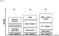
Fig 3 : Cost comparison of to Carbon Capture (#2) and Carbon Dioxide Pipelines (#3) - Renewable electric energy produced from an offshore wind park is used to electrolyze water into oxygen and hydrogen. Hydrogen is utilized in a methanation process, resulting in gaseous methane as product. Methane is fed into the gas distribution network. At a location inland connected to the gas distribution network, hydrogen is needed as feedstock, therefore, methane is taken from the gas distribution network and utilized in a moving bed methane pyrolysis process. Methane is pyrolyzed at temperatures >1000°C, the energy for the chemical reaction is supplied by renewable electric power taken from the electric grid and provided to the methane by means of resistance heating of granular pyrolytic carbon moving downwards inside the reactor. The methane pyrolysis process then results in 1 kg hydrogen and 3 kg granular pyrolytic carbon per kg of methane. The produced hydrogen is used for its designated purpose while the granular pyrolytic carbon is loaded onto a ship which transports it to the site of the methanation process.
- To store or ship the produced carbon black,
DE 10 2013 219 681 - To obtain methane in (#2), additional energy is required to capture carbon dioxide from either carbon dioxide emitting processes in the vicinity or from the atmosphere. In a step without methane pyrolysis, methane is converted to hydrogen and carbon dioxide via steam methane reforming. In (#2), the carbon dioxide is emitted to the atmosphere, thus closing the mass balance carbon loop. Present invention describes a carbon cycle not consisting of carbon dioxide emissions to the atmosphere and without costs for carbon capture or direct air capture. Example (#3) avoids carbon dioxide emissions to the atmosphere and does not require carbon capture or direct air capture. However, new infrastructure in the form of carbon dioxide pipelines is required. In contrast, present invention makes use of already existing infrastructure.
Claims (11)
- Circular carbon process comprising:a first step, wherein hydrogen is produced via water electrolysis,a second step, wherein the hydrogen produced in the first step and granular pyrolytic carbon produced in the fourth step are reacted to hydrocarbons,a third step, wherein the hydrocarbons produced in the second step are fed into a gas grid,a fourth step, wherein the hydrocarbons are taken from the gas grid, and hydrocarbons are decomposed to hydrogen and granular pyrolytic carbon,a fifth step, wherein the granular pyrolytic carbon produced in the fourth step is transported to a production site of the hydrating gasification of step two,wherein the hydrocarbons decomposition of step four is conducted in a moving or fixed bed of solid substrates and wherein the produced granular pyrolytic carbon has a bulk density in the range of 0.5 to 1.5 g/cc and has a particle size of 0.1 mm (d10) to 10 mm (d90).
- Process according to claim 1, wherein the specific surface area of the granular pyrolytic carbon measured by Hg porosimetry is in the range of 0.001 to 10 m2/g.
- Process according to claim 1 or 2, wherein the carbon content of the granular pyrolytic carbon is in the range of 98 to 100 weight-%.
- Process according to any one of claims 1 to 3, wherein methane is used as hydrocarbon and the hydrating gasification reaction is a methanation reaction.
- Process according to any one of claims 1 to 4, wherein the decomposition of step four is conducted in an electrically heated moving bed reactor, wherein the bed contains carbon-containing substrates and wherein the substrates are guided in countercurrent to the hydrocarbons.
- Process according to any one of claims 1 to 5, wherein the carbon-containing substrates have a particle size in the range of 0.1 to 10 mm and a carbon content in the range of 99.5 wt.-% to 100 wt.-% in relation to the total mass of carbon-containing substrates.
- Process according to any one of claims 1 to 6, wherein the decomposition of step four is conducted at temperatures ranging from 500 to 2000°C and pressures ranging from 1 to 100 bar.
- Process according to any one of claims 1 to 7, wherein the methane decomposition of step four is conducted in an electrically heated moving bed reactor heated by resistive heating.
- Process according to any one of claims 1 to 8, wherein the hydrogen is taken off via the top of the decomposition reactor having a temperature of 10 to 200°C and the granular pyrolytic carbon is taken off via the bottom of the decomposition reactor having a temperature of 10 to 200°C.
- Process according to any one of claims 1 to 9, wherein the granular pyrolytic carbon from the fourth step is transported as directly obtained from the methane decomposition to the production site of the hydrating gasification.
- Process according to any one of claims 1 to 10, wherein the hydrogen is used to produce ammonia, syngas, aromats, ketons, aldehydes, cyclic hydrocarbons, amins, alcohols.
Priority Applications (1)
| Application Number | Priority Date | Filing Date | Title |
|---|---|---|---|
| EP23202056.0A EP4534728A1 (en) | 2023-10-06 | 2023-10-06 | Circular carbon process |
Applications Claiming Priority (1)
| Application Number | Priority Date | Filing Date | Title |
|---|---|---|---|
| EP23202056.0A EP4534728A1 (en) | 2023-10-06 | 2023-10-06 | Circular carbon process |
Publications (1)
| Publication Number | Publication Date |
|---|---|
| EP4534728A1 true EP4534728A1 (en) | 2025-04-09 |
Family
ID=88295736
Family Applications (1)
| Application Number | Title | Priority Date | Filing Date |
|---|---|---|---|
| EP23202056.0A Withdrawn EP4534728A1 (en) | 2023-10-06 | 2023-10-06 | Circular carbon process |
Country Status (1)
| Country | Link |
|---|---|
| EP (1) | EP4534728A1 (en) |
Citations (8)
| Publication number | Priority date | Publication date | Assignee | Title |
|---|---|---|---|---|
| US2982622A (en) | 1958-09-02 | 1961-05-02 | Exxon Research Engineering Co | Hydrocarbon conversion process |
| WO2013004398A2 (en) | 2011-07-05 | 2013-01-10 | Linde Aktiengesellschaft | Method for the parallel production of hydrogen and carbon-containing products |
| DE102013219681A1 (en) | 2013-09-30 | 2015-04-02 | Marek Fulde | Method and system for storing electrical energy |
| WO2018083002A1 (en) | 2016-11-04 | 2018-05-11 | Basf Se | Method and device for carrying out endothermic gas phase-solid or gas-solid reactions |
| WO2019145279A1 (en) | 2018-01-26 | 2019-08-01 | Basf Se | Device packed with solid material for performing endothermic reactions with direct electrical heating |
| WO2020200522A1 (en) | 2019-04-05 | 2020-10-08 | Linde Gmbh | Reactor for endothermic high-temperature reactions |
| WO2021239831A1 (en) | 2020-05-27 | 2021-12-02 | Basf Se | Circular carbon process |
| WO2023057242A1 (en) | 2021-10-06 | 2023-04-13 | Basf Se | Use of carbonaceous carrier material in bed reactors |
-
2023
- 2023-10-06 EP EP23202056.0A patent/EP4534728A1/en not_active Withdrawn
Patent Citations (10)
| Publication number | Priority date | Publication date | Assignee | Title |
|---|---|---|---|---|
| US2982622A (en) | 1958-09-02 | 1961-05-02 | Exxon Research Engineering Co | Hydrocarbon conversion process |
| WO2013004398A2 (en) | 2011-07-05 | 2013-01-10 | Linde Aktiengesellschaft | Method for the parallel production of hydrogen and carbon-containing products |
| US9359200B2 (en) * | 2011-07-05 | 2016-06-07 | Basf Se | Method for the parallel production of hydrogen and carbon-containing products |
| DE102013219681A1 (en) | 2013-09-30 | 2015-04-02 | Marek Fulde | Method and system for storing electrical energy |
| US20160226088A1 (en) * | 2013-09-30 | 2016-08-04 | Marek Fulde | Method and system for storing electric energy |
| WO2018083002A1 (en) | 2016-11-04 | 2018-05-11 | Basf Se | Method and device for carrying out endothermic gas phase-solid or gas-solid reactions |
| WO2019145279A1 (en) | 2018-01-26 | 2019-08-01 | Basf Se | Device packed with solid material for performing endothermic reactions with direct electrical heating |
| WO2020200522A1 (en) | 2019-04-05 | 2020-10-08 | Linde Gmbh | Reactor for endothermic high-temperature reactions |
| WO2021239831A1 (en) | 2020-05-27 | 2021-12-02 | Basf Se | Circular carbon process |
| WO2023057242A1 (en) | 2021-10-06 | 2023-04-13 | Basf Se | Use of carbonaceous carrier material in bed reactors |
Non-Patent Citations (1)
| Title |
|---|
| DLRCHRISTOPH NOACK ET AL., FINAL REPORT BMBF FUNDED PROJECT: STUDIE UBER DIE PLANUNG EINER DEMONSTRATIONSANLAGE ZUR WASSERSTOFF- KRAFTSTOFFGEWINNUNG DURCH ELEKTROLYSE MIT ZWISCHENSPEICHERUNG IN SALZKAVERNEN UNTER DRUCK PLANDELYKAD, 2 May 2015 (2015-05-02) |
Similar Documents
| Publication | Publication Date | Title |
|---|---|---|
| US20240072286A1 (en) | Carbon-neutral process for generating electricity | |
| Lan et al. | Ammonia and related chemicals as potential indirect hydrogen storage materials | |
| US12381249B2 (en) | Carbon-neutral process for generating electricity | |
| CA3150876A1 (en) | Process for the conversion of carbon dioxide | |
| CN107973297A (en) | For the process and system by carbon dioxide conversion for carbon monoxide | |
| US20230227316A1 (en) | Circular carbon process | |
| US20220306462A1 (en) | Method for producing highly pure hydrogen by coupling pyrolysis of hydrocarbons with electrochemical hydrogen separation | |
| US9663381B2 (en) | Ammonia synthesis for fertilizer production | |
| CA2698246C (en) | A system and process for hydrocarbon synthesis | |
| KR102735963B1 (en) | Method for producing synthesis gas for use in hydroformylation reaction | |
| US20240308932A1 (en) | Method for producing synthetic fuel | |
| KR101538211B1 (en) | Plasmatron Equipment for Carbon Dioxide Destruction | |
| US20210380417A1 (en) | Process and Device for Producing Hydrogen, Carbon Monoxide and a Carbon-Containing Product | |
| CN1726077A (en) | Method for generation of a synthesis gas by catalytic partial oxidation | |
| RU2832837C1 (en) | Cyclic carbon method | |
| US20250376378A1 (en) | Carbon nanotube production method and carbon nanotube production system | |
| JP7715555B2 (en) | Synthetic fuel production method | |
| Aminjan et al. | Hydrogen production and storage | |
| Aminjan et al. | Hydrogen production and storage: Technological advancements and applications | |
| WO2025104097A1 (en) | Process of producing a fuel | |
| JP2024110487A (en) | Reactor and Carbon Recycle System | |
| WO2025026817A1 (en) | A process for the production of low carbon intensity carbon monoxide | |
| WO2025073665A1 (en) | Closed carbon loop process | |
| Kuzin | Derived gaseous fuels | |
| Liu et al. | Co2 Capture and Utilization Through Isothermal Carbonation-Calcination Looping Integrated with Msw Pyrolysis Gas Reforming |
Legal Events
| Date | Code | Title | Description |
|---|---|---|---|
| PUAI | Public reference made under article 153(3) epc to a published international application that has entered the european phase |
Free format text: ORIGINAL CODE: 0009012 |
|
| STAA | Information on the status of an ep patent application or granted ep patent |
Free format text: STATUS: THE APPLICATION HAS BEEN PUBLISHED |
|
| AK | Designated contracting states |
Kind code of ref document: A1 Designated state(s): AL AT BE BG CH CY CZ DE DK EE ES FI FR GB GR HR HU IE IS IT LI LT LU LV MC ME MK MT NL NO PL PT RO RS SE SI SK SM TR |
|
| STAA | Information on the status of an ep patent application or granted ep patent |
Free format text: STATUS: THE APPLICATION HAS BEEN WITHDRAWN |
|
| 18W | Application withdrawn |
Effective date: 20250409 |