EP4534704A1 - Hot stamping component and manufacturing method therefor - Google Patents
Hot stamping component and manufacturing method therefor Download PDFInfo
- Publication number
- EP4534704A1 EP4534704A1 EP22945045.7A EP22945045A EP4534704A1 EP 4534704 A1 EP4534704 A1 EP 4534704A1 EP 22945045 A EP22945045 A EP 22945045A EP 4534704 A1 EP4534704 A1 EP 4534704A1
- Authority
- EP
- European Patent Office
- Prior art keywords
- hot stamping
- stamping component
- base material
- depth
- component
- Prior art date
- Legal status (The legal status is an assumption and is not a legal conclusion. Google has not performed a legal analysis and makes no representation as to the accuracy of the status listed.)
- Pending
Links
Images



Classifications
-
- C—CHEMISTRY; METALLURGY
- C21—METALLURGY OF IRON
- C21D—MODIFYING THE PHYSICAL STRUCTURE OF FERROUS METALS; GENERAL DEVICES FOR HEAT TREATMENT OF FERROUS OR NON-FERROUS METALS OR ALLOYS; MAKING METAL MALLEABLE, e.g. BY DECARBURISATION OR TEMPERING
- C21D9/00—Heat treatment, e.g. annealing, hardening, quenching or tempering, adapted for particular articles; Furnaces therefor
- C21D9/46—Heat treatment, e.g. annealing, hardening, quenching or tempering, adapted for particular articles; Furnaces therefor for sheet metals
- C21D9/48—Heat treatment, e.g. annealing, hardening, quenching or tempering, adapted for particular articles; Furnaces therefor for sheet metals deep-drawing sheets
-
- B—PERFORMING OPERATIONS; TRANSPORTING
- B21—MECHANICAL METAL-WORKING WITHOUT ESSENTIALLY REMOVING MATERIAL; PUNCHING METAL
- B21D—WORKING OR PROCESSING OF SHEET METAL OR METAL TUBES, RODS OR PROFILES WITHOUT ESSENTIALLY REMOVING MATERIAL; PUNCHING METAL
- B21D22/00—Shaping without cutting, by stamping, spinning, or deep-drawing
- B21D22/02—Stamping using rigid devices or tools
- B21D22/022—Stamping using rigid devices or tools by heating the blank or stamping associated with heat treatment
-
- B—PERFORMING OPERATIONS; TRANSPORTING
- B21—MECHANICAL METAL-WORKING WITHOUT ESSENTIALLY REMOVING MATERIAL; PUNCHING METAL
- B21D—WORKING OR PROCESSING OF SHEET METAL OR METAL TUBES, RODS OR PROFILES WITHOUT ESSENTIALLY REMOVING MATERIAL; PUNCHING METAL
- B21D22/00—Shaping without cutting, by stamping, spinning, or deep-drawing
- B21D22/02—Stamping using rigid devices or tools
-
- B—PERFORMING OPERATIONS; TRANSPORTING
- B21—MECHANICAL METAL-WORKING WITHOUT ESSENTIALLY REMOVING MATERIAL; PUNCHING METAL
- B21D—WORKING OR PROCESSING OF SHEET METAL OR METAL TUBES, RODS OR PROFILES WITHOUT ESSENTIALLY REMOVING MATERIAL; PUNCHING METAL
- B21D22/00—Shaping without cutting, by stamping, spinning, or deep-drawing
- B21D22/20—Deep-drawing
- B21D22/208—Deep-drawing by heating the blank or deep-drawing associated with heat treatment
-
- B—PERFORMING OPERATIONS; TRANSPORTING
- B21—MECHANICAL METAL-WORKING WITHOUT ESSENTIALLY REMOVING MATERIAL; PUNCHING METAL
- B21D—WORKING OR PROCESSING OF SHEET METAL OR METAL TUBES, RODS OR PROFILES WITHOUT ESSENTIALLY REMOVING MATERIAL; PUNCHING METAL
- B21D37/00—Tools as parts of machines covered by this subclass
- B21D37/16—Heating or cooling
-
- B—PERFORMING OPERATIONS; TRANSPORTING
- B21—MECHANICAL METAL-WORKING WITHOUT ESSENTIALLY REMOVING MATERIAL; PUNCHING METAL
- B21D—WORKING OR PROCESSING OF SHEET METAL OR METAL TUBES, RODS OR PROFILES WITHOUT ESSENTIALLY REMOVING MATERIAL; PUNCHING METAL
- B21D53/00—Making other particular articles
- B21D53/88—Making other particular articles other parts for vehicles, e.g. cowlings, mudguards
-
- C—CHEMISTRY; METALLURGY
- C21—METALLURGY OF IRON
- C21D—MODIFYING THE PHYSICAL STRUCTURE OF FERROUS METALS; GENERAL DEVICES FOR HEAT TREATMENT OF FERROUS OR NON-FERROUS METALS OR ALLOYS; MAKING METAL MALLEABLE, e.g. BY DECARBURISATION OR TEMPERING
- C21D1/00—General methods or devices for heat treatment, e.g. annealing, hardening, quenching or tempering
- C21D1/18—Hardening; Quenching with or without subsequent tempering
-
- C—CHEMISTRY; METALLURGY
- C21—METALLURGY OF IRON
- C21D—MODIFYING THE PHYSICAL STRUCTURE OF FERROUS METALS; GENERAL DEVICES FOR HEAT TREATMENT OF FERROUS OR NON-FERROUS METALS OR ALLOYS; MAKING METAL MALLEABLE, e.g. BY DECARBURISATION OR TEMPERING
- C21D1/00—General methods or devices for heat treatment, e.g. annealing, hardening, quenching or tempering
- C21D1/34—Methods of heating
-
- C—CHEMISTRY; METALLURGY
- C21—METALLURGY OF IRON
- C21D—MODIFYING THE PHYSICAL STRUCTURE OF FERROUS METALS; GENERAL DEVICES FOR HEAT TREATMENT OF FERROUS OR NON-FERROUS METALS OR ALLOYS; MAKING METAL MALLEABLE, e.g. BY DECARBURISATION OR TEMPERING
- C21D1/00—General methods or devices for heat treatment, e.g. annealing, hardening, quenching or tempering
- C21D1/62—Quenching devices
- C21D1/673—Quenching devices for die quenching
-
- C—CHEMISTRY; METALLURGY
- C21—METALLURGY OF IRON
- C21D—MODIFYING THE PHYSICAL STRUCTURE OF FERROUS METALS; GENERAL DEVICES FOR HEAT TREATMENT OF FERROUS OR NON-FERROUS METALS OR ALLOYS; MAKING METAL MALLEABLE, e.g. BY DECARBURISATION OR TEMPERING
- C21D1/00—General methods or devices for heat treatment, e.g. annealing, hardening, quenching or tempering
- C21D1/74—Methods of treatment in inert gas, controlled atmosphere, vacuum or pulverulent material
- C21D1/76—Adjusting the composition of the atmosphere
-
- C—CHEMISTRY; METALLURGY
- C21—METALLURGY OF IRON
- C21D—MODIFYING THE PHYSICAL STRUCTURE OF FERROUS METALS; GENERAL DEVICES FOR HEAT TREATMENT OF FERROUS OR NON-FERROUS METALS OR ALLOYS; MAKING METAL MALLEABLE, e.g. BY DECARBURISATION OR TEMPERING
- C21D3/00—Diffusion processes for extraction of non-metals; Furnaces therefor
- C21D3/02—Extraction of non-metals
- C21D3/04—Decarburising
-
- C—CHEMISTRY; METALLURGY
- C21—METALLURGY OF IRON
- C21D—MODIFYING THE PHYSICAL STRUCTURE OF FERROUS METALS; GENERAL DEVICES FOR HEAT TREATMENT OF FERROUS OR NON-FERROUS METALS OR ALLOYS; MAKING METAL MALLEABLE, e.g. BY DECARBURISATION OR TEMPERING
- C21D6/00—Heat treatment of ferrous alloys
- C21D6/002—Heat treatment of ferrous alloys containing Cr
-
- C—CHEMISTRY; METALLURGY
- C21—METALLURGY OF IRON
- C21D—MODIFYING THE PHYSICAL STRUCTURE OF FERROUS METALS; GENERAL DEVICES FOR HEAT TREATMENT OF FERROUS OR NON-FERROUS METALS OR ALLOYS; MAKING METAL MALLEABLE, e.g. BY DECARBURISATION OR TEMPERING
- C21D6/00—Heat treatment of ferrous alloys
- C21D6/005—Heat treatment of ferrous alloys containing Mn
-
- C—CHEMISTRY; METALLURGY
- C21—METALLURGY OF IRON
- C21D—MODIFYING THE PHYSICAL STRUCTURE OF FERROUS METALS; GENERAL DEVICES FOR HEAT TREATMENT OF FERROUS OR NON-FERROUS METALS OR ALLOYS; MAKING METAL MALLEABLE, e.g. BY DECARBURISATION OR TEMPERING
- C21D6/00—Heat treatment of ferrous alloys
- C21D6/008—Heat treatment of ferrous alloys containing Si
-
- C—CHEMISTRY; METALLURGY
- C21—METALLURGY OF IRON
- C21D—MODIFYING THE PHYSICAL STRUCTURE OF FERROUS METALS; GENERAL DEVICES FOR HEAT TREATMENT OF FERROUS OR NON-FERROUS METALS OR ALLOYS; MAKING METAL MALLEABLE, e.g. BY DECARBURISATION OR TEMPERING
- C21D8/00—Modifying the physical properties of ferrous metals or ferrous alloys by deformation combined with, or followed by, heat treatment
-
- C—CHEMISTRY; METALLURGY
- C21—METALLURGY OF IRON
- C21D—MODIFYING THE PHYSICAL STRUCTURE OF FERROUS METALS; GENERAL DEVICES FOR HEAT TREATMENT OF FERROUS OR NON-FERROUS METALS OR ALLOYS; MAKING METAL MALLEABLE, e.g. BY DECARBURISATION OR TEMPERING
- C21D8/00—Modifying the physical properties of ferrous metals or ferrous alloys by deformation combined with, or followed by, heat treatment
- C21D8/02—Modifying the physical properties of ferrous metals or ferrous alloys by deformation combined with, or followed by, heat treatment during manufacturing of plates or strips
- C21D8/0221—Modifying the physical properties of ferrous metals or ferrous alloys by deformation combined with, or followed by, heat treatment during manufacturing of plates or strips characterised by the working steps
- C21D8/0226—Hot rolling
-
- C—CHEMISTRY; METALLURGY
- C21—METALLURGY OF IRON
- C21D—MODIFYING THE PHYSICAL STRUCTURE OF FERROUS METALS; GENERAL DEVICES FOR HEAT TREATMENT OF FERROUS OR NON-FERROUS METALS OR ALLOYS; MAKING METAL MALLEABLE, e.g. BY DECARBURISATION OR TEMPERING
- C21D8/00—Modifying the physical properties of ferrous metals or ferrous alloys by deformation combined with, or followed by, heat treatment
- C21D8/02—Modifying the physical properties of ferrous metals or ferrous alloys by deformation combined with, or followed by, heat treatment during manufacturing of plates or strips
- C21D8/0221—Modifying the physical properties of ferrous metals or ferrous alloys by deformation combined with, or followed by, heat treatment during manufacturing of plates or strips characterised by the working steps
- C21D8/0236—Cold rolling
-
- C—CHEMISTRY; METALLURGY
- C21—METALLURGY OF IRON
- C21D—MODIFYING THE PHYSICAL STRUCTURE OF FERROUS METALS; GENERAL DEVICES FOR HEAT TREATMENT OF FERROUS OR NON-FERROUS METALS OR ALLOYS; MAKING METAL MALLEABLE, e.g. BY DECARBURISATION OR TEMPERING
- C21D8/00—Modifying the physical properties of ferrous metals or ferrous alloys by deformation combined with, or followed by, heat treatment
- C21D8/02—Modifying the physical properties of ferrous metals or ferrous alloys by deformation combined with, or followed by, heat treatment during manufacturing of plates or strips
- C21D8/0247—Modifying the physical properties of ferrous metals or ferrous alloys by deformation combined with, or followed by, heat treatment during manufacturing of plates or strips characterised by the heat treatment
- C21D8/0257—Modifying the physical properties of ferrous metals or ferrous alloys by deformation combined with, or followed by, heat treatment during manufacturing of plates or strips characterised by the heat treatment with diffusion of elements, e.g. decarburising, nitriding
-
- C—CHEMISTRY; METALLURGY
- C21—METALLURGY OF IRON
- C21D—MODIFYING THE PHYSICAL STRUCTURE OF FERROUS METALS; GENERAL DEVICES FOR HEAT TREATMENT OF FERROUS OR NON-FERROUS METALS OR ALLOYS; MAKING METAL MALLEABLE, e.g. BY DECARBURISATION OR TEMPERING
- C21D8/00—Modifying the physical properties of ferrous metals or ferrous alloys by deformation combined with, or followed by, heat treatment
- C21D8/02—Modifying the physical properties of ferrous metals or ferrous alloys by deformation combined with, or followed by, heat treatment during manufacturing of plates or strips
- C21D8/0247—Modifying the physical properties of ferrous metals or ferrous alloys by deformation combined with, or followed by, heat treatment during manufacturing of plates or strips characterised by the heat treatment
- C21D8/0273—Final recrystallisation annealing
-
- C—CHEMISTRY; METALLURGY
- C21—METALLURGY OF IRON
- C21D—MODIFYING THE PHYSICAL STRUCTURE OF FERROUS METALS; GENERAL DEVICES FOR HEAT TREATMENT OF FERROUS OR NON-FERROUS METALS OR ALLOYS; MAKING METAL MALLEABLE, e.g. BY DECARBURISATION OR TEMPERING
- C21D8/00—Modifying the physical properties of ferrous metals or ferrous alloys by deformation combined with, or followed by, heat treatment
- C21D8/02—Modifying the physical properties of ferrous metals or ferrous alloys by deformation combined with, or followed by, heat treatment during manufacturing of plates or strips
- C21D8/04—Modifying the physical properties of ferrous metals or ferrous alloys by deformation combined with, or followed by, heat treatment during manufacturing of plates or strips to produce plates or strips for drawing, e.g. for deep-drawing
- C21D8/0421—Modifying the physical properties of ferrous metals or ferrous alloys by deformation combined with, or followed by, heat treatment during manufacturing of plates or strips to produce plates or strips for drawing, e.g. for deep-drawing characterised by the working steps
- C21D8/0426—Hot rolling
-
- C—CHEMISTRY; METALLURGY
- C21—METALLURGY OF IRON
- C21D—MODIFYING THE PHYSICAL STRUCTURE OF FERROUS METALS; GENERAL DEVICES FOR HEAT TREATMENT OF FERROUS OR NON-FERROUS METALS OR ALLOYS; MAKING METAL MALLEABLE, e.g. BY DECARBURISATION OR TEMPERING
- C21D8/00—Modifying the physical properties of ferrous metals or ferrous alloys by deformation combined with, or followed by, heat treatment
- C21D8/02—Modifying the physical properties of ferrous metals or ferrous alloys by deformation combined with, or followed by, heat treatment during manufacturing of plates or strips
- C21D8/04—Modifying the physical properties of ferrous metals or ferrous alloys by deformation combined with, or followed by, heat treatment during manufacturing of plates or strips to produce plates or strips for drawing, e.g. for deep-drawing
- C21D8/0447—Modifying the physical properties of ferrous metals or ferrous alloys by deformation combined with, or followed by, heat treatment during manufacturing of plates or strips to produce plates or strips for drawing, e.g. for deep-drawing characterised by the heat treatment
- C21D8/0457—Modifying the physical properties of ferrous metals or ferrous alloys by deformation combined with, or followed by, heat treatment during manufacturing of plates or strips to produce plates or strips for drawing, e.g. for deep-drawing characterised by the heat treatment with diffusion of elements, e.g. decarburising, nitriding
-
- C—CHEMISTRY; METALLURGY
- C21—METALLURGY OF IRON
- C21D—MODIFYING THE PHYSICAL STRUCTURE OF FERROUS METALS; GENERAL DEVICES FOR HEAT TREATMENT OF FERROUS OR NON-FERROUS METALS OR ALLOYS; MAKING METAL MALLEABLE, e.g. BY DECARBURISATION OR TEMPERING
- C21D8/00—Modifying the physical properties of ferrous metals or ferrous alloys by deformation combined with, or followed by, heat treatment
- C21D8/02—Modifying the physical properties of ferrous metals or ferrous alloys by deformation combined with, or followed by, heat treatment during manufacturing of plates or strips
- C21D8/04—Modifying the physical properties of ferrous metals or ferrous alloys by deformation combined with, or followed by, heat treatment during manufacturing of plates or strips to produce plates or strips for drawing, e.g. for deep-drawing
- C21D8/0447—Modifying the physical properties of ferrous metals or ferrous alloys by deformation combined with, or followed by, heat treatment during manufacturing of plates or strips to produce plates or strips for drawing, e.g. for deep-drawing characterised by the heat treatment
- C21D8/0463—Modifying the physical properties of ferrous metals or ferrous alloys by deformation combined with, or followed by, heat treatment during manufacturing of plates or strips to produce plates or strips for drawing, e.g. for deep-drawing characterised by the heat treatment following hot rolling
-
- C—CHEMISTRY; METALLURGY
- C21—METALLURGY OF IRON
- C21D—MODIFYING THE PHYSICAL STRUCTURE OF FERROUS METALS; GENERAL DEVICES FOR HEAT TREATMENT OF FERROUS OR NON-FERROUS METALS OR ALLOYS; MAKING METAL MALLEABLE, e.g. BY DECARBURISATION OR TEMPERING
- C21D8/00—Modifying the physical properties of ferrous metals or ferrous alloys by deformation combined with, or followed by, heat treatment
- C21D8/02—Modifying the physical properties of ferrous metals or ferrous alloys by deformation combined with, or followed by, heat treatment during manufacturing of plates or strips
- C21D8/04—Modifying the physical properties of ferrous metals or ferrous alloys by deformation combined with, or followed by, heat treatment during manufacturing of plates or strips to produce plates or strips for drawing, e.g. for deep-drawing
- C21D8/0447—Modifying the physical properties of ferrous metals or ferrous alloys by deformation combined with, or followed by, heat treatment during manufacturing of plates or strips to produce plates or strips for drawing, e.g. for deep-drawing characterised by the heat treatment
- C21D8/0473—Final recrystallisation annealing
-
- C—CHEMISTRY; METALLURGY
- C21—METALLURGY OF IRON
- C21D—MODIFYING THE PHYSICAL STRUCTURE OF FERROUS METALS; GENERAL DEVICES FOR HEAT TREATMENT OF FERROUS OR NON-FERROUS METALS OR ALLOYS; MAKING METAL MALLEABLE, e.g. BY DECARBURISATION OR TEMPERING
- C21D9/00—Heat treatment, e.g. annealing, hardening, quenching or tempering, adapted for particular articles; Furnaces therefor
- C21D9/0068—Heat treatment, e.g. annealing, hardening, quenching or tempering, adapted for particular articles; Furnaces therefor for particular articles not mentioned below
-
- C—CHEMISTRY; METALLURGY
- C21—METALLURGY OF IRON
- C21D—MODIFYING THE PHYSICAL STRUCTURE OF FERROUS METALS; GENERAL DEVICES FOR HEAT TREATMENT OF FERROUS OR NON-FERROUS METALS OR ALLOYS; MAKING METAL MALLEABLE, e.g. BY DECARBURISATION OR TEMPERING
- C21D9/00—Heat treatment, e.g. annealing, hardening, quenching or tempering, adapted for particular articles; Furnaces therefor
- C21D9/46—Heat treatment, e.g. annealing, hardening, quenching or tempering, adapted for particular articles; Furnaces therefor for sheet metals
-
- C—CHEMISTRY; METALLURGY
- C22—METALLURGY; FERROUS OR NON-FERROUS ALLOYS; TREATMENT OF ALLOYS OR NON-FERROUS METALS
- C22C—ALLOYS
- C22C38/00—Ferrous alloys, e.g. steel alloys
- C22C38/002—Ferrous alloys, e.g. steel alloys containing In, Mg, or other elements not provided for in one single group C22C38/001 - C22C38/60
-
- C—CHEMISTRY; METALLURGY
- C22—METALLURGY; FERROUS OR NON-FERROUS ALLOYS; TREATMENT OF ALLOYS OR NON-FERROUS METALS
- C22C—ALLOYS
- C22C38/00—Ferrous alloys, e.g. steel alloys
- C22C38/02—Ferrous alloys, e.g. steel alloys containing silicon
-
- C—CHEMISTRY; METALLURGY
- C22—METALLURGY; FERROUS OR NON-FERROUS ALLOYS; TREATMENT OF ALLOYS OR NON-FERROUS METALS
- C22C—ALLOYS
- C22C38/00—Ferrous alloys, e.g. steel alloys
- C22C38/04—Ferrous alloys, e.g. steel alloys containing manganese
-
- C—CHEMISTRY; METALLURGY
- C22—METALLURGY; FERROUS OR NON-FERROUS ALLOYS; TREATMENT OF ALLOYS OR NON-FERROUS METALS
- C22C—ALLOYS
- C22C38/00—Ferrous alloys, e.g. steel alloys
- C22C38/18—Ferrous alloys, e.g. steel alloys containing chromium
- C22C38/24—Ferrous alloys, e.g. steel alloys containing chromium with vanadium
-
- C—CHEMISTRY; METALLURGY
- C22—METALLURGY; FERROUS OR NON-FERROUS ALLOYS; TREATMENT OF ALLOYS OR NON-FERROUS METALS
- C22C—ALLOYS
- C22C38/00—Ferrous alloys, e.g. steel alloys
- C22C38/18—Ferrous alloys, e.g. steel alloys containing chromium
- C22C38/26—Ferrous alloys, e.g. steel alloys containing chromium with niobium or tantalum
-
- C—CHEMISTRY; METALLURGY
- C22—METALLURGY; FERROUS OR NON-FERROUS ALLOYS; TREATMENT OF ALLOYS OR NON-FERROUS METALS
- C22C—ALLOYS
- C22C38/00—Ferrous alloys, e.g. steel alloys
- C22C38/18—Ferrous alloys, e.g. steel alloys containing chromium
- C22C38/28—Ferrous alloys, e.g. steel alloys containing chromium with titanium or zirconium
-
- C—CHEMISTRY; METALLURGY
- C22—METALLURGY; FERROUS OR NON-FERROUS ALLOYS; TREATMENT OF ALLOYS OR NON-FERROUS METALS
- C22C—ALLOYS
- C22C38/00—Ferrous alloys, e.g. steel alloys
- C22C38/18—Ferrous alloys, e.g. steel alloys containing chromium
- C22C38/32—Ferrous alloys, e.g. steel alloys containing chromium with boron
-
- C—CHEMISTRY; METALLURGY
- C22—METALLURGY; FERROUS OR NON-FERROUS ALLOYS; TREATMENT OF ALLOYS OR NON-FERROUS METALS
- C22C—ALLOYS
- C22C38/00—Ferrous alloys, e.g. steel alloys
- C22C38/18—Ferrous alloys, e.g. steel alloys containing chromium
- C22C38/38—Ferrous alloys, e.g. steel alloys containing chromium with more than 1.5% by weight of manganese
-
- C—CHEMISTRY; METALLURGY
- C22—METALLURGY; FERROUS OR NON-FERROUS ALLOYS; TREATMENT OF ALLOYS OR NON-FERROUS METALS
- C22C—ALLOYS
- C22C38/00—Ferrous alloys, e.g. steel alloys
- C22C38/18—Ferrous alloys, e.g. steel alloys containing chromium
- C22C38/40—Ferrous alloys, e.g. steel alloys containing chromium with nickel
- C22C38/48—Ferrous alloys, e.g. steel alloys containing chromium with nickel with niobium or tantalum
-
- C—CHEMISTRY; METALLURGY
- C22—METALLURGY; FERROUS OR NON-FERROUS ALLOYS; TREATMENT OF ALLOYS OR NON-FERROUS METALS
- C22C—ALLOYS
- C22C38/00—Ferrous alloys, e.g. steel alloys
- C22C38/18—Ferrous alloys, e.g. steel alloys containing chromium
- C22C38/40—Ferrous alloys, e.g. steel alloys containing chromium with nickel
- C22C38/50—Ferrous alloys, e.g. steel alloys containing chromium with nickel with titanium or zirconium
-
- C—CHEMISTRY; METALLURGY
- C22—METALLURGY; FERROUS OR NON-FERROUS ALLOYS; TREATMENT OF ALLOYS OR NON-FERROUS METALS
- C22C—ALLOYS
- C22C38/00—Ferrous alloys, e.g. steel alloys
- C22C38/60—Ferrous alloys, e.g. steel alloys containing lead, selenium, tellurium, or antimony, or more than 0.04% by weight of sulfur
-
- C—CHEMISTRY; METALLURGY
- C23—COATING METALLIC MATERIAL; COATING MATERIAL WITH METALLIC MATERIAL; CHEMICAL SURFACE TREATMENT; DIFFUSION TREATMENT OF METALLIC MATERIAL; COATING BY VACUUM EVAPORATION, BY SPUTTERING, BY ION IMPLANTATION OR BY CHEMICAL VAPOUR DEPOSITION, IN GENERAL; INHIBITING CORROSION OF METALLIC MATERIAL OR INCRUSTATION IN GENERAL
- C23C—COATING METALLIC MATERIAL; COATING MATERIAL WITH METALLIC MATERIAL; SURFACE TREATMENT OF METALLIC MATERIAL BY DIFFUSION INTO THE SURFACE, BY CHEMICAL CONVERSION OR SUBSTITUTION; COATING BY VACUUM EVAPORATION, BY SPUTTERING, BY ION IMPLANTATION OR BY CHEMICAL VAPOUR DEPOSITION, IN GENERAL
- C23C2/00—Hot-dipping or immersion processes for applying the coating material in the molten state without affecting the shape; Apparatus therefor
- C23C2/02—Pretreatment of the material to be coated, e.g. for coating on selected surface areas
-
- C—CHEMISTRY; METALLURGY
- C23—COATING METALLIC MATERIAL; COATING MATERIAL WITH METALLIC MATERIAL; CHEMICAL SURFACE TREATMENT; DIFFUSION TREATMENT OF METALLIC MATERIAL; COATING BY VACUUM EVAPORATION, BY SPUTTERING, BY ION IMPLANTATION OR BY CHEMICAL VAPOUR DEPOSITION, IN GENERAL; INHIBITING CORROSION OF METALLIC MATERIAL OR INCRUSTATION IN GENERAL
- C23C—COATING METALLIC MATERIAL; COATING MATERIAL WITH METALLIC MATERIAL; SURFACE TREATMENT OF METALLIC MATERIAL BY DIFFUSION INTO THE SURFACE, BY CHEMICAL CONVERSION OR SUBSTITUTION; COATING BY VACUUM EVAPORATION, BY SPUTTERING, BY ION IMPLANTATION OR BY CHEMICAL VAPOUR DEPOSITION, IN GENERAL
- C23C2/00—Hot-dipping or immersion processes for applying the coating material in the molten state without affecting the shape; Apparatus therefor
- C23C2/02—Pretreatment of the material to be coated, e.g. for coating on selected surface areas
- C23C2/022—Pretreatment of the material to be coated, e.g. for coating on selected surface areas by heating
- C23C2/0224—Two or more thermal pretreatments
-
- C—CHEMISTRY; METALLURGY
- C23—COATING METALLIC MATERIAL; COATING MATERIAL WITH METALLIC MATERIAL; CHEMICAL SURFACE TREATMENT; DIFFUSION TREATMENT OF METALLIC MATERIAL; COATING BY VACUUM EVAPORATION, BY SPUTTERING, BY ION IMPLANTATION OR BY CHEMICAL VAPOUR DEPOSITION, IN GENERAL; INHIBITING CORROSION OF METALLIC MATERIAL OR INCRUSTATION IN GENERAL
- C23C—COATING METALLIC MATERIAL; COATING MATERIAL WITH METALLIC MATERIAL; SURFACE TREATMENT OF METALLIC MATERIAL BY DIFFUSION INTO THE SURFACE, BY CHEMICAL CONVERSION OR SUBSTITUTION; COATING BY VACUUM EVAPORATION, BY SPUTTERING, BY ION IMPLANTATION OR BY CHEMICAL VAPOUR DEPOSITION, IN GENERAL
- C23C2/00—Hot-dipping or immersion processes for applying the coating material in the molten state without affecting the shape; Apparatus therefor
- C23C2/04—Hot-dipping or immersion processes for applying the coating material in the molten state without affecting the shape; Apparatus therefor characterised by the coating material
- C23C2/06—Zinc or cadmium or alloys based thereon
-
- C—CHEMISTRY; METALLURGY
- C23—COATING METALLIC MATERIAL; COATING MATERIAL WITH METALLIC MATERIAL; CHEMICAL SURFACE TREATMENT; DIFFUSION TREATMENT OF METALLIC MATERIAL; COATING BY VACUUM EVAPORATION, BY SPUTTERING, BY ION IMPLANTATION OR BY CHEMICAL VAPOUR DEPOSITION, IN GENERAL; INHIBITING CORROSION OF METALLIC MATERIAL OR INCRUSTATION IN GENERAL
- C23C—COATING METALLIC MATERIAL; COATING MATERIAL WITH METALLIC MATERIAL; SURFACE TREATMENT OF METALLIC MATERIAL BY DIFFUSION INTO THE SURFACE, BY CHEMICAL CONVERSION OR SUBSTITUTION; COATING BY VACUUM EVAPORATION, BY SPUTTERING, BY ION IMPLANTATION OR BY CHEMICAL VAPOUR DEPOSITION, IN GENERAL
- C23C2/00—Hot-dipping or immersion processes for applying the coating material in the molten state without affecting the shape; Apparatus therefor
- C23C2/04—Hot-dipping or immersion processes for applying the coating material in the molten state without affecting the shape; Apparatus therefor characterised by the coating material
- C23C2/12—Aluminium or alloys based thereon
-
- C—CHEMISTRY; METALLURGY
- C23—COATING METALLIC MATERIAL; COATING MATERIAL WITH METALLIC MATERIAL; CHEMICAL SURFACE TREATMENT; DIFFUSION TREATMENT OF METALLIC MATERIAL; COATING BY VACUUM EVAPORATION, BY SPUTTERING, BY ION IMPLANTATION OR BY CHEMICAL VAPOUR DEPOSITION, IN GENERAL; INHIBITING CORROSION OF METALLIC MATERIAL OR INCRUSTATION IN GENERAL
- C23C—COATING METALLIC MATERIAL; COATING MATERIAL WITH METALLIC MATERIAL; SURFACE TREATMENT OF METALLIC MATERIAL BY DIFFUSION INTO THE SURFACE, BY CHEMICAL CONVERSION OR SUBSTITUTION; COATING BY VACUUM EVAPORATION, BY SPUTTERING, BY ION IMPLANTATION OR BY CHEMICAL VAPOUR DEPOSITION, IN GENERAL
- C23C2/00—Hot-dipping or immersion processes for applying the coating material in the molten state without affecting the shape; Apparatus therefor
- C23C2/26—After-treatment
- C23C2/28—Thermal after-treatment, e.g. treatment in oil bath
-
- C—CHEMISTRY; METALLURGY
- C23—COATING METALLIC MATERIAL; COATING MATERIAL WITH METALLIC MATERIAL; CHEMICAL SURFACE TREATMENT; DIFFUSION TREATMENT OF METALLIC MATERIAL; COATING BY VACUUM EVAPORATION, BY SPUTTERING, BY ION IMPLANTATION OR BY CHEMICAL VAPOUR DEPOSITION, IN GENERAL; INHIBITING CORROSION OF METALLIC MATERIAL OR INCRUSTATION IN GENERAL
- C23C—COATING METALLIC MATERIAL; COATING MATERIAL WITH METALLIC MATERIAL; SURFACE TREATMENT OF METALLIC MATERIAL BY DIFFUSION INTO THE SURFACE, BY CHEMICAL CONVERSION OR SUBSTITUTION; COATING BY VACUUM EVAPORATION, BY SPUTTERING, BY ION IMPLANTATION OR BY CHEMICAL VAPOUR DEPOSITION, IN GENERAL
- C23C2/00—Hot-dipping or immersion processes for applying the coating material in the molten state without affecting the shape; Apparatus therefor
- C23C2/26—After-treatment
- C23C2/28—Thermal after-treatment, e.g. treatment in oil bath
- C23C2/29—Cooling or quenching
-
- C—CHEMISTRY; METALLURGY
- C23—COATING METALLIC MATERIAL; COATING MATERIAL WITH METALLIC MATERIAL; CHEMICAL SURFACE TREATMENT; DIFFUSION TREATMENT OF METALLIC MATERIAL; COATING BY VACUUM EVAPORATION, BY SPUTTERING, BY ION IMPLANTATION OR BY CHEMICAL VAPOUR DEPOSITION, IN GENERAL; INHIBITING CORROSION OF METALLIC MATERIAL OR INCRUSTATION IN GENERAL
- C23C—COATING METALLIC MATERIAL; COATING MATERIAL WITH METALLIC MATERIAL; SURFACE TREATMENT OF METALLIC MATERIAL BY DIFFUSION INTO THE SURFACE, BY CHEMICAL CONVERSION OR SUBSTITUTION; COATING BY VACUUM EVAPORATION, BY SPUTTERING, BY ION IMPLANTATION OR BY CHEMICAL VAPOUR DEPOSITION, IN GENERAL
- C23C2/00—Hot-dipping or immersion processes for applying the coating material in the molten state without affecting the shape; Apparatus therefor
- C23C2/34—Hot-dipping or immersion processes for applying the coating material in the molten state without affecting the shape; Apparatus therefor characterised by the shape of the material to be treated
- C23C2/36—Elongated material
- C23C2/40—Plates; Strips
-
- C—CHEMISTRY; METALLURGY
- C21—METALLURGY OF IRON
- C21D—MODIFYING THE PHYSICAL STRUCTURE OF FERROUS METALS; GENERAL DEVICES FOR HEAT TREATMENT OF FERROUS OR NON-FERROUS METALS OR ALLOYS; MAKING METAL MALLEABLE, e.g. BY DECARBURISATION OR TEMPERING
- C21D2211/00—Microstructure comprising significant phases
- C21D2211/008—Martensite
Definitions
- the present disclosure relates to a hot stamping component and a manufacturing method therefor.
- a hot stamping process generally includes heating/forming/cooling/trimming, and may use phase transformation of materials and a change in microstructures during the process.
- a hot stamping steel In order to improve the toughness of hot stamping steel, research has been actively conducted on a method of improving the toughness of a base material by using alloy components.
- Embodiments of the present disclosure may improve the toughness of a manufactured hot stamping component by appropriately forming a decarburization layer and an inner oxide layer on a surface of a base material, and at the same time, may prevent cracks from occurring during hot stamping forming.
- An embodiment of the present disclosure provides a hot stamping component including: a base material; a decarburization layer located on a surface of the base material; and an inner oxide layer located on a surface of the decarburization layer, wherein the hot stamping component has a tensile strength (TS) of 1350 MPa to 1680 MPa, and a hardness of the hot stamping component within a depth of 50 ⁇ m from a surface of the hot stamping component in a plate thickness direction of the hot stamping component and an average hardness of the hot stamping component satisfy Relational Expression 1.
- TS tensile strength
- a / B ⁇ 0.7 (In Relational Expression 1, A denotes the hardness (Hv( ⁇ 50 ⁇ m)) within the depth of 50 ⁇ m in the plate thickness direction of the hot stamping component, and B denotes the average hardness (Hv(avg.)) of the hot stamping component.)
- a depth of the inner oxide layer may satisfy Relational Expression 2.
- C ⁇ 5 ⁇ m (In Relational Expression 2, C denotes the depth of the inner oxide layer in the plate thickness direction of the hot stamping component.)
- the hot stamping component may have a VDA bending angle of 60° or more.
- the hot stamping component may have a yield strength (YP) of 900 MPa to 1300 MPa and an elongation (EL) of 4% to 10%.
- the hot stamping component may have a microstructure with a martensite fraction of 90% or more.
- the hot stamping component may further include a plating layer located on a surface of the inner oxide layer.
- a thickness of the plating layer may be 10 ⁇ m to 30 ⁇ m.
- Another embodiment of the present disclosure provides a method of manufacturing a hot stamping component, including: forming a blank by cutting a plated steel sheet having a plating layer formed on at least one surface of a base material; and heating the blank in a heating furnace having a plurality of sections with different temperature ranges, wherein the heating of the blank includes: a multi-stage heating step of heating the blank stepwise; and a soaking step of heating the stepwise heated blank to a temperature of Ac1 to 910°C, wherein a hardness of the hot stamping component within a depth of 50 ⁇ m from a surface of the hot stamping component in a plate thickness direction of the hot stamping component and an average hardness of the hot stamping component satisfy Relational Expression 3.
- a / B ⁇ 0.7 (In Relational Expression 3, A denotes the hardness (Hv( ⁇ 50 ⁇ m)) within the depth of 50 ⁇ m in the plate thickness direction of the hot stamping component, and B denotes the average hardness (Hv(avg.)) of the hot stamping component.)
- a dew point of an annealing furnace of the base material may be -15°C to +15°C.
- an annealing temperature of the base material may be 750°C to 900°C.
- the method of manufacturing a hot stamping component may further include: after the heating of the blank, transferring the heated blank; forming a molded body by pressing the transferred blank with a mold; and cooling the formed molded body.
- the hot stamping component may further include: a decarburization layer formed on a surface of the base material; and an inner oxide layer formed on a surface of the decarburization layer.
- a depth of the inner oxide layer may satisfy Relational Expression 4.
- C ⁇ 5 ⁇ m (In Relational Expression 4, C denotes the depth of the inner oxide layer in the plate thickness direction of the hot stamping component.)
- the toughness of a manufactured hot stamping component may be improved.
- an inner oxide layer formed on a surface of the decarburization layer is provided below a preset depth, cracks may be prevented from occurring during a hot stamping process.
- a layer, region, or component when referred to as being "on" another layer, region, or component, it may be directly on the other layer, region, or component, or may be indirectly on the other layer, region, or component with intervening layers, regions, or components therebetween.
- a and/or B is used herein to select only A, select only B, or select both A and B. Also, “at least one of A and B” is used herein to select only A, select only B, or select both A and B.
- a plan view of an object refers to "a view of an object seen from above
- a cross-sectional view of an object refers to "a view of an object vertically cut and seen from the side.
- FIG. 1 is a cross-sectional view schematically illustrating a hot stamping component, according to an embodiment of the present disclosure.
- a hot stamping component 1 may include a base material 100, a decarburization layer 200, an inner oxide layer 300, and a plating layer 400.
- the base material 100, the decarburization layer 200, the inner oxide layer 300, and the plating layer 400 may be sequentially stacked in a plate thickness direction of the hot stamping component 1.
- the base material 100 may include carbon (C), silicon (Si), manganese (Mn), phosphorus (P), sulfur (S), chromium (Cr), boron (B), remaining iron (Fe), and other unavoidable impurities.
- the base material 100 may include about 0.15 wt% to about 0.3 wt% of carbon (C), about 0.05 wt% to about 0.8 wt% of silicon (Si), about 0.8 wt% to about 3.0 wt% of manganese (Mn), more than 0 wt% but not more than about 0.1 wt% of phosphorus (P), more than 0 wt% but not more than about 0.1 wt% of sulfur (S), about 0.1 wt% to about 0.9 wt% of chromium (Cr), about 0.001 wt% to about 0.005 wt% of boron (B), remaining iron (Fe), and other unavoidable impurities.
- C carbon
- Si silicon
- Mn manganese
- P phosphorus
- S sulfur
- Cr chromium
- B boron
- Fe remaining iron
- the base material 100 may further include at least one component from among titanium (Ti), niobium (Nb), and vanadium (V). Also, the base material 100 may further include calcium (Ca).
- the base material 100 may further include at least one component from among about 0.01 wt% to about 0.1 wt% of titanium (Ti), about 0.01 wt% to about 0.1 wt% of niobium (Nb), about 0.01 wt% to about 0.1 wt% of vanadium (V), and about 0.0001 wt% to about 0.01 wt% of calcium (Ca).
- Carbon (C) is a major element that determines the strength and hardness of steel, and may be added to ensure a tensile strength of a steel material after a hot stamping (or hot pressing) process. Also, carbon (C) may be added to ensure hardenability characteristics of the steel material. In an embodiment, carbon (C) may be included in an amount of about 0.15 wt% to about 0.3 wt% based on a total weight of the base material 100. When carbon (C) is included in an amount less than about 0.15 wt% based on the total weight of the base material 100, it may be difficult to achieve a desired mechanical strength. On the other hand, when carbon (C) is included in an amount more than about 0.3 wt% based on the total weight of the base material 100, the toughness of the steel material may be reduced or a problem of controlling brittleness of steel may occur.
- Silicon (Si) may function as a ferrite stabilizing element in the base material 100. Silicon (Si) may improve ductility by purifying ferrite, and may improve a carbon concentration in austenite by suppressing formation of low-temperature carbide. Furthermore, silicon (Si) may be a key element for hot-rolled, cold-rolled, and hot-stamped structure homogenization (perlite and manganese segregation control) and ferrite microdispersion. In an embodiment, silicon (Si) may be included in an amount of about 0.05 wt% to about 0.8 wt% based on the total weight of the base material 100.
- silicon (Si) When silicon (Si) is included in an amount less than about 0.05 wt% based on the total weight of the base material 100, the above-described effects may not be sufficiently obtained. On the other hand, when silicon (Si) is included in an amount greater than about 0.8 wt% based on the total weight of the base material 100, hot rolling and cold rolling loads may increase, hot rolling red scale may be excessive, and adhesion may deteriorate.
- Manganese (Mn) may be added to increase hardenability and strength during heat treatment.
- manganese (Mn) may be included in an amount of about 0.8 wt% to about 3.0 wt% based on the total weight of the base material 100.
- manganese (Mn) is included in an amount less than about 0.8 wt% based on the total weight of the base material 100, there may be a high possibility that a material after hot stamping is insufficient (e.g., insufficient hard phase fraction) due to insufficient hardenability.
- manganese (Mn) when included in an amount greater than about 3.0 wt% based on the total weight of the base material 100, ductility and toughness may be reduced due to manganese (Mn) segregation or perlite bands, bending performance may be reduced, and a inhomogeneous microstructure may be generated.
- Phosphorus (P) may be an element that easily segregates and reduces the toughness of steel.
- phosphorus (P) may be included in an amount more than 0 wt% and less than or equal to about 0.1 wt% based on the total weight of the base material 100.
- a decrease in the toughness of steel may be prevented.
- phosphorus (P) is included in an amount greater than about 0.1 wt% based on the total weight of the base material 100, cracks may occur during the process, and an iron phosphide compound may be formed, thereby reducing the toughness of steel.
- Sulfur (S) may be an element that reduces workability and physical properties.
- sulfur (S) may be included in an amount more than 0 wt% and less than or equal to about 0.1 wt% based on the total weight of the base material 100.
- sulfur (S) is included in an amount greater than about 0.1 wt% based on the total weight of the base material 100, hot workability may be reduced, and surface defects such as cracks may occur due to formation of large inclusions.
- Chromium (Cr) may be added to improve the hardenability and strength of steel.
- chromium (Cr) may be included in an amount of about 0.1 wt% to about 0.9 wt% based on the total weight of the base material 100.
- the hardenability and strength of steel may be improved, an increase in production cost may be prevented, and a decrease in the toughness of the steel material may be prevented.
- Boron (B) is added to ensure the hardenability and strength of steel by securing a martensite structure, and may have a grain refinement effect by increasing an austenite grain growth temperature.
- boron (B) may be included in an amount of about 0.001 wt% to about 0.005 wt% based on the total weight of the base material 100. When boron (B) is included in above range based on the total weight of the base material 100, hard grain boundary brittleness may be prevented and high toughness and bendability may be ensured.
- Titanium (Ti) may be added to strengthen hardenability and improve a material by forming precipitates after hot stamping heat treatment. Also, titanium (Ti) may effectively contribute to refinement of austenite grains by forming a precipitated phase such as Ti (C,N) at a high temperature.
- titanium (Ti) may be included in an amount of about 0.01 wt% to about 0.1 wt% based on the total weight of the base material 100. When titanium (Ti) is included in the above range based on the total weight of the base material 100, continuous casting defects may be prevented, coarsening of precipitates may be prevented, physical properties of the steel material may be easily ensured, and cracks on a surface of the steel material may be prevented or minimized.
- Niobium (Nb) may be added to increase strength and toughness according to a decrease in a martensite packet size.
- niobium (Nb) may be included in an amount of about 0.01 wt% to about 0.1 wt% based on the total weight of the base material 100.
- the grain refinement effect of the steel material may be high in hot rolling and cold rolling processes, cracks in a slob and brittle fracture of a product during steelmaking/casting may be prevented, and formation of coarse precipitates in steelmaking may be minimized.
- Vanadium (V) may be added to increase the strength of steel through a precipitation strengthening effect by forming precipitates.
- vanadium (V) may be included in an amount of about 0.01 wt% to about 0.1 wt% based on the total weight of the base material 100. When vanadium (V) is included in the above range based on the total weight of the base material 100, the strength of the steel material may be improved.
- Calcium (Ca) may be added to form CaS to reduce the content of sulfur in steel, and to prevent formation of MnS inclusions that are drawn during hot rolling and induce defects such as hook cracks during electrical resistance welding.
- the base material 100 may have a microstructure with a martensite fraction of 90% or more.
- the base material 100 may have a microstructure including 90% or more of martensite, and less than 10% of remaining other unavoidable structures and other precipitates.
- the decarburization layer 200 may be located on the base material 100.
- the decarburization layer 200 may be located on a surface of the base material 100.
- the toughness of the hot stamping component 1 may be improved.
- a layer having a hardness of about 70% or less compared to an average hardness at about 1/4 point in the plate thickness direction of the hot stamping component 1 from the surface of the base material 100 may be defined as the decarburization layer 200.
- a layer having a hardness of about 70% or less compared to the average hardness at about 1/4 point in the plate thickness direction of the hot stamping component 1 from a surface of the hot stamping component 1 may be defined as the decarburization layer 200. That is, an average hardness of the decarburization layer 200 may be about 70% or less of the average hardness at about 1/4 point in the plate thickness direction of the hot stamping component 1 from the surface of the base material 100 or from the surface of the hot stamping component 1. In other words, the average hardness of the decarburization layer 200 may be about 70% or less of the average hardness at about 1/4 point in the plate thickness direction of the hot stamping component 1 from the surface of the base material 100 or from the surface of the hot stamping component 1.
- the inner oxide layer 300 may be located on the decarburization layer 200.
- the inner oxide layer 300 may be located on a surface of the decarburization layer 200.
- the inner oxide layer 300 may include silicon (Si), manganese (Mn), chromium (Cr), etc.
- a depth (or thickness t1) of the inner oxide layer 300 may be about 5 ⁇ m in the plate thickness direction of the hot stamping component 1, which will be described below in more detail.
- the plating layer 400 may be located on the inner oxide layer 300.
- the plating layer 400 may be located on a surface of the inner oxide layer 300.
- the plating layer 400 may be a zinc (Zn)-based plating layer or an aluminum (Al)-based plating layer.
- the plating layer 400 may include zinc (Zn) and/or aluminum (Al).
- the plating layer 400 when the plating layer 400 is a zinc (Zn)-based plating layer, the plating layer 400 may include iron (Fe), aluminum (Al), manganese (Mn), silicon (Si), remaining zinc (Zn), and other unavoidable impurities.
- the plating layer 400 may include about 10 wt% to about 70 wt% of iron (Fe), more than 0 wt% but not more than about 5 wt% of aluminum (Al), more than 0 wt% but not more than about 1 wt% of manganese (Mn), more than 0 wt% but not more than about 1 wt% of silicon (Si), remaining zinc (Zn), and other unavoidable impurities.
- the plating layer 400 may have a depth (or thickness t2) of about 10 ⁇ m to about 30 ⁇ m in the plate thickness direction of the hot stamping component 1.
- a depth (or thickness t2) of about 10 ⁇ m to about 30 ⁇ m in the plate thickness direction of the hot stamping component 1.
- the plating layer 400 has the thickness t2 of about 10 ⁇ m to about 30 ⁇ m, the surface of the base material (or steel material) may be protected, and at the same time, a decrease in the toughness of the hot stamping component 1 may be prevented or minimized.
- the decarburization layer 200 is softer than the base material 100, and when the hot stamping component 1 includes the decarburization layer 200, the toughness of the hot stamping component 1 including the decarburization layer 200 may be improved.
- the depth (or thickness t1) of the inner oxide layer 300 when the depth (or thickness t1) of the inner oxide layer 300 is too large, liquid zinc may more easily penetrate into the base material 100 by the inner oxide layer 300, the risk of cracks during hot stamping forming may increase, and thus, the bendability of the manufactured hot stamping component 1 may be reduced.
- the depth (or the thickness t1) of the inner oxide layer 300 is greater than about 5 ⁇ m, liquid zinc may more easily penetrate into the base material 100 due to the inner oxide layer 300, the risk of cracks during hot stamping forming may increase, and thus, the bendability of the manufactured hot stamping component 1 may be reduced.
- the decarburization layer 200 may be formed on the base material 100 in an annealing step.
- the inner oxide layer 300 may be simultaneously formed on the decarburization layer 200.
- the decarburization layer 200 may be formed on the surface of the base material 100, and at the same time, the inner oxide layer 300 may be formed on the surface of the decarburization layer 200.
- a depth (or thickness) of the decarburization layer 200 may increase.
- the depth (or thickness) of the inner oxide layer 300 may also increase. That is, in order to increase the toughness of the hot stamping component 1, the depth (or thickness) of the decarburization layer 200 should increase.
- the depth (or thickness) of the inner oxide layer 300 may also increase, thereby increasing the risk of cracks during hot stamping forming and reducing the bendability of the manufactured hot stamping component 1. Accordingly, it is necessary to appropriately adjust the depth (or thickness) of the decarburization layer 200 and the depth (or thickness) of the inner oxide layer 300.
- the inventors of the present disclosure have derived Relational Expressions 1 and 2 through excessively repeated experiments to enable the hot stamping component 1 to have a VDA bending angle of about 60° or more.
- the hot stamping component 1 may satisfy Relational Expressions 1 and 2.
- a hardness within a depth of about 50 ⁇ m in the plate thickness direction of the hot stamping component 1 from the surface of the hot stamping component 1 and an average hardness of the hot stamping component 1 may satisfy Relational Expression 1
- the depth (or thickness) of the inner oxide layer 300 may satisfy Relational Expression 2.
- the hot stamping component 1 may satisfy both Relational Expression 1 and Relational Expression 2.
- A denotes the hardness (Hv( ⁇ 50 ⁇ m)) within the depth (or thickness) of about 50 ⁇ m in the plate thickness direction of the hot stamping component 1
- B denotes the average hardness (Hv(avg.)) of the hot stamping component 1.
- the hardness within the depth of about 50 ⁇ m in the plate thickness direction of the hot stamping component 1 from the surface of the hot stamping component 1 may be a hardness value measured with a Vickers hardness tester at a depth of about 50 ⁇ m or less in the plate thickness direction of the hot stamping component 1 from the surface of the hot stamping component 1, and the average hardness (Hv(avg.)) of the hot stamping component 1 may be a hardness value measured with the Vickers hardness tester at about 1/4 point in the plate thickness direction of the hot stamping component 1.
- C denotes the depth (or thickness) of the inner oxide layer 300 in the plate thickness direction of the hot stamping component 1.
- the decarburization layer 200 may be located on a portion adjacent to the surface of the hot stamping component 1. Because the decarburization layer 200 is softer than the base material 100, a hardness of a portion of the hot stamping component 1 adjacent to the surface of the hot stamping component 1 may be lower than the average hardness of the hot stamping component 1. In this case, when the depth (or thickness) of the decarburization layer 200 increases, a difference between the hardness of the portion of the hot stamping component 1 adjacent to the surface of the hot stamping component 1 and the average hardness of the hot stamping component 1 may increase.
- the depth (or thickness) of the decarburization layer 200 decreases, a difference between the hardness of the portion of the hot stamping component 1 adjacent to the surface of the hot stamping component 1 and the average hardness of the hot stamping component 1 may decrease.
- the decarburization layer 200 is not formed (or provided) to a sufficient depth (or thickness), and thus, the toughness of the hot stamping component 1 including the decarburization layer 200 may be low.
- a VDA bending angle of the hot stamping component 1 may be less than about 60°.
- the ratio between the hardness (Hv( ⁇ 50 ⁇ m)) within the depth (or thickness) of about 50 ⁇ m in the plate thickness direction of the hot stamping component 1 and the average hardness (Hv(avg.)) of the hot stamping component 1 is equal to or less than 0.7,it may mean that the decarburization layer 200 is formed (or provided) to a sufficient depth (or thickness).
- the hot stamping component 1 when the ratio between the hardness (Hv( ⁇ 50 ⁇ m)) within the depth (or thickness) of about 50 ⁇ m in the plate thickness direction of the hot stamping component 1 and the average hardness (Hv(avg.)) of the hot stamping component 1 satisfies about 0.7 or less, the decarburization layer 200 is formed (or provided) to a sufficient depth (or thickness), and thus, the toughness of the hot stamping component 1 including the decarburization layer 200 may be improved.
- the hot stamping component 1 may have a VDA bending angle of about 60° or more.
- the depth (or thickness) of the inner oxide layer 300 included in the hot stamping component 1 may be about 5 ⁇ m or less.
- liquid metal embrittlement may occur due to a low melting point of zinc, which may cause cracks to occur inside and may reduce the bendability of the hot stamping component 1.
- LME liquid metal embrittlement
- the depth (or thickness) of the inner oxide layer 300 is large, liquid zinc may more easily penetrate into the inside due to the inner oxide layer 300, the risk of cracks during hot stamping forming may increase, and thus, the bendability of the manufactured hot stamping component 1 may be reduced.
- the depth (or thickness) of the inner oxide layer 300 is greater than about 5 ⁇ m, liquid zinc may more easily penetrate into the inside due to the inner oxide layer 300, the risk of cracks during hot stamping forming may increase, and thus, the bendability of the manufactured hot stamping component 1 may be reduced.
- the depth (or thickness) of the inner oxide layer 300 is about 5 ⁇ m or less in the plate thickness direction of the hot stamping component 1, cracks may be prevented from occurring during hot stamping, and thus, the high-temperature formability of the hot stamping component (or blank) may be improved.
- the hot stamping component 1 may satisfy Relational Expression 1 and Relational Expression 2 at the same time.
- the hot stamping component 1 may have high toughness and the high-temperature formability of the hot stamping component 1 may be excellent.
- the hot stamping component 1 may have high toughness and the high-temperature formability of the hot stamping component 1 may be excellent.
- the hot stamping component 1 when the hot stamping component 1 satisfies both Relational Expression 1 and Relational Expression 2, the hot stamping component 1 may have a tensile strength (TS) of about 1350 MPa to about 1680 MPa, a yield strength (YP) of about 900 MPa to about 1300 MPa, and an elongation (EL) of about 4% to about 10%. Also, the hot stamping component 1 may have a VDA bending angle of about 60° or more. In this case, the VDA bending angle may be measured in accordance with the VDA standard (VDA238-100).
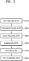
- FIG. 2 is a flowchart schematically illustrating a method of manufacturing a hot stamping component, according to an embodiment of the present disclosure.
- FIGS. 3 to 5 are cross-sectional views schematically illustrating a method of manufacturing a hot stamping component, according to an embodiment of the present disclosure.
- a method of manufacturing the hot stamping component 1 may include a hot rolling step S100, a cooling/coiling step S200, a cold rolling step S300, an annealing step S400, a plating step S500, and a hot stamping step S600.
- a reheating step of the base material 100 (e.g., steel slab) prepared with the composition described with reference to FIG. 1 may be performed.
- the steel slab reheating step the steel slab obtained through a continuous casting process may be reheated to a certain temperature so that components segregated during casting are resolved.
- a slab reheating temperature (SRT) may be about 1,200°C to about 1,400°C.
- SRT slab reheating temperature
- the components segregated during the casting may not be sufficiently resolved, and thus, it may be difficult to have the homogenization effect of alloy elements significantly and it may be difficult to have the solution effect of titanium (Ti) significantly.
- the slab reheating temperature (SRT) When the slab reheating temperature (SRT) is high, the slab reheating temperature (SRT) is favorable for homogenization. However, when the slab reheating temperature (SRT) is higher than about 1,400°C, an austenite crystal grain size may increase, and thus, it may be difficult to ensure strength and the manufacturing cost of a steel sheet may increase due to an excessive heating process.
- the reheated base material 100 may be hot-rolled at a certain finishing rolling temperature.
- a hot-rolled steel sheet may be manufactured through the hot rolling step S100.
- a finishing delivery temperature (FDT) may be about 880°C to about 950°C.
- the finishing delivery temperature (FDT) is lower than about 880°C, the workability of the steel sheet may not be ensured due to the occurrence of a mixed grain structure caused by abnormal area rolling, workability may be reduced due to microstructure unevenness, and a passing ability problem may occur during hot rolling due to a rapid phase change.
- the finishing delivery temperature (FDT) is higher than about 950°C, austenite grains may be coarsened, TiC precipitates may be coarsened, and thus, the performance of the hot stamping component may deteriorate.
- the hot-rolled base material 100 may be cooled and coiled to a certain coiling temperature (CT).
- CT coiling temperature
- the coiling temperature (CT) of the cooling/coiling step S300 may be about 550°C to about 800°C.
- the coiling temperature (CT) may affect the redistribution of carbon (C), and when the coiling temperature (CT) is lower than about 550°C, a low-temperature phase fraction may increase due to subcooling, strength may increase, a rolling load may increase during cold rolling, and ductility may rapidly decrease.
- CT coiling temperature
- the coiling temperature (CT) is higher than about 800°C, abnormal crystal grain growth or excessive crystal grain growth may cause deterioration in formability and strength.
- the coiled base material 100 may be uncoiled, pickled, and then cold rolled.
- the pickling may be performed to remove scale from the coiled steel sheet (or base material), that is, a hot-rolled coil manufactured through the hot rolling process described above.
- a cold-rolled steel sheet may be manufactured through the cold rolling step S300.
- the cold-rolled base material 100 may be annealed at a temperature of about 700°C or more.
- the annealing step S400 may include heating the cold-rolled base material 100 and cooling the heated base material 100 at a certain cooling rate.
- the base material may be annealed in the annealing step S400.
- the annealing step S400 may be performed in an annealing furnace.
- the annealing of the base material 100 may be performed in a gas atmosphere including about 0.5 vol% to about 25 vol% of hydrogen and remaining nitrogen.
- water may be sprayed into the annealing furnace together with hydrogen gas and nitrogen gas.
- a dew point of the annealing furnace may increase. Accordingly, the dew point of the annealing furnace may be controlled by controlling the amount of water sprayed into the annealing furnace.
- the decarburization layer 200 may be formed on the base material 100.
- carbon may be lost from a surface of the base material 100 to form the decarburization layer 200.
- the inner oxide layer 300 may be formed on the decarburization layer 200. That is, the decarburization layer 200 may be formed on the surface of the base material 100, and the inner oxide layer 300 may be formed on a surface of the decarburization layer 200.
- the decarburization layer 200 and the inner oxide layer 300 may be layers obtained by changing a portion of the base material 100.
- a layer having a hardness of about 80% or less compared to an average hardness at about 1/4 point from the surface of the base material 100 may be defined as the decarburization layer 200. That is, an average hardness of the decarburization layer 200 may be about 80% or less of the average hardness at about 1/4 point from the surface of the base material 100.
- the dew point of the annealing furnace where the annealing of the base material 100 is performed may be about -15°C to about +15°C.
- the decarburization layer 200 is formed on the base material 100 in order to improve the toughness of the manufactured hot stamping component 1.
- a depth (or thickness) of the decarburization layer 200 may be too small, and thus, the effect of improving the toughness of the manufactured hot stamping component may be insignificant.
- a depth (or thickness t3) of the inner oxide layer 300 may be too large, and thus LME cracks may occur and operability may be reduced due to equipment oxidation.
- a large amount of water should be supplied to the annealing furnace in order to increase the dew point of the annealing furnace.
- equipment of the annealing furnace may be oxidized, and it may take a long time to clean the equipment, thereby reducing operability.
- the depth (or thickness) of the decarburization layer 200 and the depth (or thickness t3) of the inner oxide layer 300 may increase, and thus, cracks may occur inside during high-temperature forming due to the inner oxide layer 300. Accordingly, when the dew point of the annealing furnace where the annealing of the base material 100 is performed satisfies about -15°C to about +15°C, the toughness of the manufactured hot stamping component 1 may be improved and the efficiency of a manufacturing process may be improved.
- a line speed of the annealing furnace where the annealing of the base material 100 is performed may be about 30 meters per minute (mpm) to about 200 mpm.
- mpm meters per minute
- a moving speed of the base material 100 may be too slow, which may lead to a sharp decrease in productivity.
- the line speed of the annealing furnace is about 200 mpm or more, a staying time of the base material 100 in the annealing furnace may be too short, the depth (or thickness) of the decarburization layer 200 may decrease, and thus, the effect of improving the toughness of the manufactured hot stamping component may be insignificant.
- the productivity of the hot stamping component may be improved, and at the same time, the toughness of the manufactured hot stamping component may be improved.
- an annealing temperature of the base material 100 may be about 750°C to about 900°C.
- the annealing temperature of the base material 100 is lower than about 750°C, a desired structure may not be obtained, and recrystallization may not be sufficiently completed.
- the annealing temperature of the base material 100 is higher than about 900°C, the annealing temperature may be too high, and thus, the efficiency of the manufacturing process may be reduced. Accordingly, when the annealing temperature of the base material 100 satisfies about 750°C to about 900°C, a desired structure may be obtained, recrystallization may be sufficiently completed, and the efficiency of the manufacturing process may be improved.
- the plating step S500 may be a step of forming the plating layer 400 on the annealed base material 100.
- the plating layer 400 may be formed on the annealed base material 100 through the plating step S500.
- the plating layer 400 may be formed on a surface of the inner oxide layer 300 through the plating step S500.
- the plating layer 400 may include a zinc (Z)-based plating layer or an aluminum (Al)-based plating layer.
- the annealed base material 100 may be immersed in a plating bath.
- the plating bath may be maintained at a temperature of about 400°C to about 700°C.
- the adhesion amount of the plating layer may be about 40 g/m 2 to about 200 g/m 2 on both surfaces of the base material 100 (or the inner oxide layer 300).
- a depth (or thickness t4) of the plating layer 400 formed on the base material 100 or the decarburization layer 200 may be about 5 ⁇ m to about 20 ⁇ m in the plate thickness direction of the base material 100.
- the depth (or thickness) of the plating layer 400 is about 5 ⁇ m or less, the sacrificial method of the plating layer 400 may be insufficient.
- the depth (or thickness) of the plating layer 400 is about 20 ⁇ m or more, the cost of forming the plating layer 400 may increase, thereby reducing economic feasibility. Accordingly, when the depth (or thickness t4) of the plating layer 400 satisfies about 5 ⁇ m to about 20 ⁇ m, corrosion of the base material 100 of the hot stamping component 1 may be prevented or minimized.
- the annealing step S400 and the plating step S500 may be performed on the same line. Accordingly, a line speed at which the plating step S500 is performed may be about 30 mpm to about 200 mpm. When the line speed is about 30 mpm or less, the line speed may be too slow, and thus, productivity may be reduced. A plating amount is controlled by using an air knife. When the line speed is about 200 mpm or more, the line speed may be too fast, and thus, it may be difficult to control the plating amount by using the air knife. Accordingly, when the line speed at which the plating step S500 is performed satisfies about 30 mpm to about 200 mpm, productivity may be improved, and at the same time, the plating amount may be easily controlled.
- a plated steel sheet having the plating layer 400 formed on at least one surface of the base material 100 may be manufactured through the plating step S500.
- the plated steel sheet may include the base material 100, the decarburization layer 200 formed on the base material 100, the inner oxide layer 300 formed on the decarburization layer 200, and the plating layer 400 formed on the inner oxide layer 300.
- the plated steel sheet may include the base material 100, the decarburization layer 200 formed on the surface of the base material 100, the inner oxide layer 300 formed on the surface of the decarburization layer 200, and the plating layer 400 formed on the surface of the inner oxide layer 300.
- FIG. 6 is a flowchart schematically illustrating a hot stamping step, according to an embodiment of the present disclosure.
- FIG. 7 is a flowchart schematically illustrating a heating step, according to an embodiment of the present disclosure.
- the hot stamping step S600 may be performed after the plating step S500 (see FIG. 2 ).
- the hot stamping step S600 may include a heating step S610, a transferring step S620, a forming step S630, and a cooling step S640.
- a blank may be formed by cutting the plated steel sheet having the plating layer 400 (see FIG. 5 ) formed on at least one surface of the base material 100 (see FIG. 5 ).
- the decarburization layer 200 (see FIG. 5 ) and the inner oxide layer 300 (see FIG. 5 ) may be located between the base material 100 and the plating layer 400.
- the blank may be heated in a heating furnace having a plurality of sections with different temperature ranges.
- the heating step S610 may include a multi-stage heating step S611 and a soaking step S612.
- the multi-stage heating step S611 and the soaking step S612 may be steps in which the blank is heated while passing through the plurality of sections provided in the heating furnace.
- an overall temperature of the heating furnace may be about 680°C to about 910°C.
- the overall temperature of the heating furnace where the multi-stage heating step S611 and the soaking step S612 are performed may be about 680°C to about 910°C.
- a temperature of the heating furnace where the multi-stage heating step S611 is performed may be about 680°C to about Ac1
- a temperature of the heating furnace where the soaking step S612 is performed may be about Ac1 to about 910°C.
- the blank may be heated stepwise while passing through the plurality of sections provided in the heating furnace. From among the plurality of sections provided in the heating furnace, there may be a plurality of sections in which the multi-stage heating step S611 is performed, and a temperature may be set for each section so as to increase in a direction from an inlet of the heating furnace into which the blank is inserted to an outlet of the heating furnace from which the blank is taken out, and thus, a temperature of the blank may be raised in stages.
- the soaking step S612 may be performed after the multi-stage heating step S611.
- the stepwise heated blank may be heated (or soaked) while passing through a section of the heating furnace set to a temperature of about Ac1 to about 910°C. From among the plurality of sections provided in the heating furnace, there may be at least one section in which the soaking step S612 is performed.
- FIG. 8 is a diagram for describing a heating furnace having a plurality of sections, in a heating step of a method of manufacturing a hot stamping component, according to an embodiment of the present disclosure.
- a heating furnace may include a plurality of sections with different temperature ranges.
- the heating furnace may include a first section P 1 with a first temperature range T 1 , a second section P 2 with a second temperature range T 2 , a third section P 3 with a third temperature range T 3 , a fourth section P 4 with a fourth temperature range T 4 , a fifth section P 5 with a fifth temperature range T 5 , a sixth section P 6 with a sixth temperature range T 6 , and a seventh section P 7 with a seventh temperature range T 7 .
- a blank in the multi-stage heating step S611, may be heated stepwise while passing through the first section P 1 to the fourth section P 4 defined in the heating furnace. Also, in the soaking step S612, the blank stepwise heated in the first section P 1 to the fourth section P 4 may be soaked while passing through the fifth section P 5 to the seventh section P 7 .
- the first section P 1 to the seventh section P 7 may be sequentially arranged in the heating furnace.
- the first section P 1 with the first temperature range T 1 may be adjacent to an inlet of the heating furnace into which the blank is inserted, and the seventh section P 7 with the seventh temperature range T 7 may be adjacent to an outlet of the heating furnace from which the blank is taken out.
- the first section P 1 with the first temperature range T 1 may be a first section of the heating furnace, and the seventh section P 7 with the seventh temperature range T 7 may be a last section of the heating furnace.
- Temperatures of the plurality of sections provided in the heating furnace may increase in a direction from the inlet of the heating furnace into which the blank is inserted to the outlet of the heating furnace from which the blank is taken out.
- temperatures of the fifth section P 5 , the sixth section P 6 , and the seventh section P 7 may be the same.
- a temperature difference between two adjacent sections from among the plurality of sections provided in the heating furnace may be greater than about 0°C and less than or equal to about 100°C.
- a temperature difference between the first section P 1 and the second section P 2 may be greater than about 0°C and less than or equal to about 100°C.
- a heating furnace temperature of the soaking step S612 may be about Ac1 to about 910°C.
- the manufactured hot stamping component may not have a desired material.
- zinc (Zn) included in the plating layer 400 may be vaporized, resulting in loss of the plating layer 400. Accordingly, when the heating furnace temperature of the soaking step S612 satisfies about Ac1 to about 910°C, the manufactured hot stamping component may be formed of a desired material, and loss of the plating layer 400 may be prevented.
- the heating furnace includes seven sections with different temperature ranges in FIG. 8 , the present disclosure is not limited thereto.
- the heating furnace may include five, sixth, or eight sections with different temperature ranges.
- the heating step S610 includes the multi-stage heating step S611 and the soaking step S612, a temperature of the heating furnace may be set in stages, and thus, the energy efficiency of the heating furnace may be improved.
- the heating furnace may have a length of about 20 m to about 40 m along a transfer path of the blank.
- the heating furnace may include the plurality of sections with different temperature ranges, and a ratio between a length of a section where the blank is stepwise heated and a length of a section where the blank is soaked from among the plurality of sections may satisfy about 1:1 to about 4:1.
- the length of the section where the blank is soaked in the heating furnace increases and the ratio between the length of the section where the blank is stepwise heated and the length of the section where the blank is soaked is greater than about 1:1, the amount of hydrogen penetrating into the blank in the soaking section may increase, thereby increasing delayed fracture.
- the soaking section (or time) is not sufficiently secured, and thus, the strength of the hot stamping component manufactured by the process of manufacturing a hot stamping component may be uneven.
- the length of the soaking section from among the plurality of sections provided in the heating furnace may be about 20% to about 50% of a total length of the heating furnace.
- a total heating time during which the heating step S610 is performed may be about 2 min to about 20 min. That is, a total time during which the blank stays in the heating furnace may be about 2 min to about 20 min.
- a heating time may be insufficient and thus, the manufactured hot stamping component 1 may not have a desired material.
- the total heating time during which the heating step S610 is performed is about 20 min or more, a heating time may be too long and thus, a production speed may decrease and economic feasibility may decrease.
- the manufactured hot stamping component 1 may have a desired material, and at the same time, a decrease in the economic feasibility of the manufacturing process may be prevented or minimized.
- the heating step S610 the transferring step S620, the forming step S630, and the cooling step S640 may be further performed.
- the transferring step S620 may be a step of transferring the heated blank from the heating furnace to a mold.
- the heated blank may be cooled to an atmospheric temperature (or room temperature). That is, the heated blank may be air-cooled during transfer.
- a mold entry temperature e.g., forming start temperature
- wrinkles or bends
- the heated blank is air-cooled during transfer.
- the forming step S630 may be a step of hot stamping the transferred blank to form a molded body.
- the blank may be pressed with the mold to form a molded body.
- the forming start temperature may be about 500°C to about 700°C.
- the forming start temperature may be too low, and thus, the formability of the blank may decrease, and the manufactured hot stamping component 1 may not have a desired structure and properties.
- the forming start temperature is higher than about 700°C, wrinkles (or bends) may occur on the surface of the manufactured hot stamping component 1. Also, the plating layer 400 may stick to the mold.
- the formability of the blank may be improved, the manufactured hot stamping component 1 may have a desired structure and properties, and the occurrence of wrinkles (or bends) on the surface of the manufactured hot stamping component 1 may be prevented or minimized.
- the cooling step S640 may be a step of cooling the molded body.
- the cooling step S640 may be performed in the mold in which the blank is pressed.
- a final product may be formed by cooling the molded body at the same time as forming the molded body into a final component shape.
- a cooling channel through which a refrigerant circulates may be provided in the mold.
- the molded body may be rapidly cooled by circulation of the refrigerant supplied through the cooling channel provided in the mold.
- the blank in order to prevent a spring back phenomenon of a plate material and maintain a desired shape, the blank may be pressed and rapidly cooled while the mold is closed.
- the molded body may be cooled at an average cooling rate of at least about 10°C/s to a martensite end temperature.
- a cooling end temperature at which the cooling step S640 ends may be about room temperature to about 200°C.
- the productivity of the manufacturing process may decrease.
- the cooling end temperature is higher than about 200°C, the manufactured hot stamping component 1 is air-cooled at room temperature, and in this case, distortion may occur in the hot stamping component 1, and it may be difficult to secure a target material. Accordingly, when the cooling end temperature at which the cooling step S640 ends satisfies room temperature to about 200°C, the productivity of the manufacturing process may be improved, and distortion of the manufactured hot stamping component 1 may be prevented or minimized.
- the inventors of the present disclosure have derived Relational Expressions 3 and 4 through excessively repeated experiments to enable the manufactured hot stamping component 1 to have a VDA bending angle of about 60° or more.
- the manufactured hot stamping component 1 may satisfy Relational Expressions 3 and 4.
- a hardness within a depth of 50 ⁇ m in the plate thickness direction of the hot stamping component 1 from the surface of the hot stamping component 1 and an average hardness of the hot stamping component 1 may satisfy Relational Expression 3
- a depth (or thickness) of the inner oxide layer 300 may satisfy Relational Expression 4.
- the hot stamping component 1 may satisfy both Relational Expression 3 and Relational Expression 4.
- A denotes the hardness (Hv( ⁇ 50 ⁇ m)) within the depth (or thickness) of about 50 ⁇ m in the plate thickness direction of the hot stamping component 1
- B denotes the average hardness (Hv(avg.)) of the hot stamping component 1.
- the hardness within the depth of about 50 ⁇ m in the plate thickness direction of the hot stamping component 1 from the surface of the hot stamping component 1 may be a hardness value measured with a Vickers hardness tester at a depth of about 50 ⁇ m or less in the plate thickness direction of the hot stamping component 1 from the surface of the hot stamping component 1, and the average hardness (Hv(avg.)) of the hot stamping component 1 may be a hardness value measured with the Vickers hardness tester at about 1/4 point in the plate thickness direction of the hot stamping component 1.
- C denotes the depth (or thickness) of the inner oxide layer 300 in the plate thickness direction of the hot stamping component 1.
- the toughness of the hot stamping component 1 manufactured through the method of manufacturing a hot stamping component may be improved.
- the hot stamping component 1 manufactured through the method of manufacturing a hot stamping component may have a VDA bending angle of about 60° or more.
- the hot stamping component 1 manufactured through the method of manufacturing a hot stamping component may have a tensile strength (TS) of about 1350 MPa to about 1680 MPa, a yield strength (YP) of about 900 MPa to about 1300 MPa, and an elongation (EL) of about 4% to about 10%.
- TS tensile strength
- YP yield strength
- EL elongation
- Embodiment 1, Embodiment 2, Comparative Example 1, and Comparative Example 2 are hot stamping components (samples) manufactured using a slab having a composition shown in Table 1 under process conditions shown in Table 2.
- Table 3 A/B C( ⁇ m) VDA bending angle (°) Crack depth ( ⁇ m) Embodiment 1 0.70 1.3 72.19 2.8 Embodiment 2 0.39 5 75.44 4.1 Comparative Example 1 0.33 7.1 58.96 15.2 Comparative Example 2 0.72 0.1 54.77 1.0
- A denotes the hardness (Hv( ⁇ 50 ⁇ m)) within the depth (or thickness) of about 50 ⁇ m in the plate thickness direction of the hot stamping component
- B denotes the average hardness (Hv(avg.)) of the hot stamping component
- C denotes the depth (or thickness) of the inner oxide layer 300 in the plate thickness direction of the hot stamping component.
- the hardness within the depth of about 50 ⁇ m in the plate thickness direction of the hot stamping component 1 from the surface of the hot stamping component 1 may be a hardness value measured with a Vickers hardness tester at a depth of about 50 ⁇ m or less in the plate thickness direction of the hot stamping component 1 from the surface of the hot stamping component 1, and the average hardness (Hv(avg.)) of the hot stamping component 1 may be a hardness value measured with the Vickers hardness tester at about 1/4 point in the plate thickness direction of the hot stamping component 1.
- the VDA bending angle was evaluated by using the VDA standard (VDA238-100), and the crack depth was measured by using a scanning electron microscope.
- the crack depth corresponds to a deepest crack depth measured through the scanning electron microscope.
- the VDA bending angle of the hot stamping component required by the present disclosure is 60° or more. Also, when the crack depth in the hot stamping component is large, the VDA bending angle of the hot stamping component may decrease, and the toughness of the hot stamping component may decrease. Accordingly, the crack depth in the hot stamping component required by the present disclosure is 10 ⁇ m or less. When the crack depth is out of the range, it corresponds to a case where the required conditions are not satisfied.
- Embodiments 1 and 2 correspond to a case where both Relational Expression 1 ((A / B) ⁇ 0.7) and Relational Expression 2 (C ⁇ 5) are satisfied, Comparative Example 1 corresponds to a case where Relational Expression 2 (C ⁇ 5) is not satisfied, and Comparative Example 2 corresponds to a case where Relational Expression 1 ((A / B) ⁇ 0.7) is not satisfied.
- Embodiment 1, Embodiment 2, Comparative Example 1, and Comparative Example 2 correspond to samples manufactured using the base material 100 (or steel sheet) satisfying the composition of FIG. 1 according to the method of manufacturing a hot stamping component. However, Comparative Example 1 and Comparative Example 2 are samples that do not satisfy Relational Expression 1 ((A / B) ⁇ 0.7) and/or Relational Expression 2 (C ⁇ 5) due to a difference in process control conditions.
- Relational Expression 2 (C ⁇ 5) when Relational Expression 2 (C ⁇ 5) is not satisfied, it may be found that the VDA bending angle and the crack depth do not satisfy the required conditions. In detail, when Relational Expression 2 (C ⁇ 5) is not satisfied, it may be found that the VDA bending angle is less than 60° and the crack depth is greater than 10 ⁇ m.
- Relational Expression 1 ((A / B) ⁇ 0.7) is not satisfied, it may be found that the VDA bending angle does not satisfy the required condition. In detail, when Relational Expression 1 ((A / B) ⁇ 0.7) is not satisfied, it may be found that the VDA bending angle is less than 60°.
- the hot stamping component 1 when the hot stamping component 1 satisfies both Relational Expression 1 ((A / B) ⁇ 0.7) and Relational Expression 2 (C ⁇ 5), the hot stamping component 1 may have the required VDA bending angle, and the crack depth in the hot stamping component 1 may be formed below a preset value. That is, when the hot stamping component 1 satisfies both Relational Expression 1 ((A / B) ⁇ 0.7) and Relational Expression 2 (C ⁇ 5), the hot stamping component 1 may have excellent toughness and high-temperature formability.
Landscapes
- Chemical & Material Sciences (AREA)
- Engineering & Computer Science (AREA)
- Mechanical Engineering (AREA)
- Materials Engineering (AREA)
- Metallurgy (AREA)
- Organic Chemistry (AREA)
- Thermal Sciences (AREA)
- Physics & Mathematics (AREA)
- Crystallography & Structural Chemistry (AREA)
- Chemical Kinetics & Catalysis (AREA)
- Oil, Petroleum & Natural Gas (AREA)
- Heat Treatment Of Articles (AREA)
- Shaping Metal By Deep-Drawing, Or The Like (AREA)
- Heat Treatment Of Sheet Steel (AREA)
Abstract
The present disclosure provides a hot stamping component including: a base material; a decarburization layer located on the base material; and an inner oxide layer located on the decarburization layer, wherein the hot stamping component has a tensile strength (TS) of 1350 MPa to 1680 MPa, and a hardness of the hot stamping component within a depth of 50 µm from a surface of the hot stamping component in a plate thickness direction of the hot stamping component and an average hardness of the hot stamping component satisfy Relational Expression 1. 
(In Relational Expression 1, A denotes the hardness (Hv(≤50 µm)) within the depth of 50 µm in the plate thickness direction of the hot stamping component, and B denotes the average hardness (Hv(avg.)) of the hot stamping component.)
Description
- The present disclosure relates to a hot stamping component and a manufacturing method therefor.
- As environmental regulations and fuel economy-related regulations are strengthened worldwide, the need for lighter materials for vehicles is increasing. Accordingly, research on and development of ultra-high-strength steel and hot stamping steel have been actively conducted.
- A hot stamping process generally includes heating/forming/cooling/trimming, and may use phase transformation of materials and a change in microstructures during the process. In order to improve the toughness of hot stamping steel, research has been actively conducted on a method of improving the toughness of a base material by using alloy components.
- However, when alloy components are changed or increased, the cost may increase and economical feasibility may decrease.
- Related technologies include
Korean Patent Publication No. 10-2021-0129902 - Embodiments of the present disclosure may improve the toughness of a manufactured hot stamping component by appropriately forming a decarburization layer and an inner oxide layer on a surface of a base material, and at the same time, may prevent cracks from occurring during hot stamping forming.
- An embodiment of the present disclosure provides a hot stamping component including: a base material; a decarburization layer located on a surface of the base material; and an inner oxide layer located on a surface of the decarburization layer, wherein the hot stamping component has a tensile strength (TS) of 1350 MPa to 1680 MPa, and a hardness of the hot stamping component within a depth of 50 µm from a surface of the hot stamping component in a plate thickness direction of the hot stamping component and an average hardness of the hot stamping component satisfy Relational Expression 1.

- In the present embodiment, a depth of the inner oxide layer may satisfy Relational Expression 2.

- In the present embodiment, the hot stamping component may have a VDA bending angle of 60° or more.
- In the present embodiment, the hot stamping component may have a yield strength (YP) of 900 MPa to 1300 MPa and an elongation (EL) of 4% to 10%.
- In the present embodiment, the hot stamping component may have a microstructure with a martensite fraction of 90% or more.
- In the present embodiment, the hot stamping component may further include a plating layer located on a surface of the inner oxide layer.
- In the present embodiment, a thickness of the plating layer may be 10 µm to 30 µm.
- Another embodiment of the present disclosure provides a method of manufacturing a hot stamping component, including: forming a blank by cutting a plated steel sheet having a plating layer formed on at least one surface of a base material; and heating the blank in a heating furnace having a plurality of sections with different temperature ranges, wherein the heating of the blank includes: a multi-stage heating step of heating the blank stepwise; and a soaking step of heating the stepwise heated blank to a temperature of Ac1 to 910°C, wherein a hardness of the hot stamping component within a depth of 50 µm from a surface of the hot stamping component in a plate thickness direction of the hot stamping component and an average hardness of the hot stamping component satisfy Relational Expression 3.

- In the present embodiment, a dew point of an annealing furnace of the base material may be -15°C to +15°C.
- In the present embodiment, an annealing temperature of the base material may be 750°C to 900°C.
- In the present embodiment, the method of manufacturing a hot stamping component may further include: after the heating of the blank, transferring the heated blank; forming a molded body by pressing the transferred blank with a mold; and cooling the formed molded body.
- In the present embodiment, the hot stamping component may further include: a decarburization layer formed on a surface of the base material; and an inner oxide layer formed on a surface of the decarburization layer.
- In the present embodiment, a depth of the inner oxide layer may satisfy Relational Expression 4.

- Other aspects, features, and advantages of the present disclosure will become more apparent from the detailed description, the claims, and the drawings for implementing the present disclosure.
- According to an embodiment of the present disclosure as described above, because a decarburization layer is formed on a surface of a base material, the toughness of a manufactured hot stamping component may be improved.
- Also, according to an embodiment of the present disclosure, because an inner oxide layer formed on a surface of the decarburization layer is provided below a preset depth, cracks may be prevented from occurring during a hot stamping process.
-
-
FIG. 1 is a cross-sectional view schematically illustrating a hot stamping component, according to an embodiment of the present disclosure. -
FIG. 2 is a flowchart schematically illustrating a method of manufacturing a hot stamping component, according to an embodiment of the present disclosure. -
FIGS. 3 to 5 are cross-sectional views schematically illustrating a method of manufacturing a hot stamping component, according to an embodiment of the present disclosure. -
FIG. 6 is a flowchart schematically illustrating a hot stamping step, according to an embodiment of the present disclosure. -
FIG. 7 is a flowchart schematically illustrating a heating step, according to an embodiment of the present disclosure. -
FIG. 8 is a diagram for describing a heating furnace having a plurality of sections, in a heating step of a method of manufacturing a hot stamping component, according to an embodiment of the present disclosure. - As the present disclosure allows for various changes and numerous embodiments, certain embodiments will be illustrated in the drawings and described in the detailed description. Effects and features of the present disclosure, and methods for achieving them will be clarified with reference to embodiments described below in detail with reference to the drawings. However, the present disclosure is not limited to the following embodiments and may be embodied in various forms.
- Although the terms "first," "second," etc. may be used to describe various elements, these elements should not be limited by these terms. These terms are only used to distinguish one element from another.
- As used herein, the singular forms "a," "an," and "the" are intended to include the plural forms as well, unless the context clearly indicates otherwise.
- It will be further understood that the terms "comprises" or "comprising" used herein specify the presence of stated features or components, but do not preclude the presence or addition of one or more other features or components.
- It will be further understood that, when a layer, region, or component is referred to as being "on" another layer, region, or component, it may be directly on the other layer, region, or component, or may be indirectly on the other layer, region, or component with intervening layers, regions, or components therebetween.
- Sizes of components in the drawings may be exaggerated or reduced for convenience of explanation. For example, because sizes and thicknesses of elements in the drawings are arbitrarily illustrated for convenience of explanation, the present disclosure is not limited thereto.
- "A and/or B" is used herein to select only A, select only B, or select both A and B. Also, "at least one of A and B" is used herein to select only A, select only B, or select both A and B.
- In the following embodiments, "a plan view of an object" refers to "a view of an object seen from above, and "a cross-sectional view of an object" refers to "a view of an object vertically cut and seen from the side. In the following embodiments, when elements "overlap," it may mean that the elements overlap in a "plan view" and a "cross-sectional view".
- Hereinafter, embodiments of the present disclosure will be described in detail with reference to the accompanying drawings, wherein the same or corresponding elements are denoted by the same reference numerals throughout.
-
FIG. 1 is a cross-sectional view schematically illustrating a hot stamping component, according to an embodiment of the present disclosure. - Referring to
FIG. 1 , a hot stamping component 1 according to an embodiment may include abase material 100, adecarburization layer 200, aninner oxide layer 300, and aplating layer 400. Thebase material 100, thedecarburization layer 200, theinner oxide layer 300, and theplating layer 400 may be sequentially stacked in a plate thickness direction of the hot stamping component 1. - In an embodiment, the
base material 100 may include carbon (C), silicon (Si), manganese (Mn), phosphorus (P), sulfur (S), chromium (Cr), boron (B), remaining iron (Fe), and other unavoidable impurities. For example, thebase material 100 may include about 0.15 wt% to about 0.3 wt% of carbon (C), about 0.05 wt% to about 0.8 wt% of silicon (Si), about 0.8 wt% to about 3.0 wt% of manganese (Mn), more than 0 wt% but not more than about 0.1 wt% of phosphorus (P), more than 0 wt% but not more than about 0.1 wt% of sulfur (S), about 0.1 wt% to about 0.9 wt% of chromium (Cr), about 0.001 wt% to about 0.005 wt% of boron (B), remaining iron (Fe), and other unavoidable impurities. - Also, the
base material 100 may further include at least one component from among titanium (Ti), niobium (Nb), and vanadium (V). Also, thebase material 100 may further include calcium (Ca). For example, thebase material 100 may further include at least one component from among about 0.01 wt% to about 0.1 wt% of titanium (Ti), about 0.01 wt% to about 0.1 wt% of niobium (Nb), about 0.01 wt% to about 0.1 wt% of vanadium (V), and about 0.0001 wt% to about 0.01 wt% of calcium (Ca). - Carbon (C) is a major element that determines the strength and hardness of steel, and may be added to ensure a tensile strength of a steel material after a hot stamping (or hot pressing) process. Also, carbon (C) may be added to ensure hardenability characteristics of the steel material. In an embodiment, carbon (C) may be included in an amount of about 0.15 wt% to about 0.3 wt% based on a total weight of the
base material 100. When carbon (C) is included in an amount less than about 0.15 wt% based on the total weight of thebase material 100, it may be difficult to achieve a desired mechanical strength. On the other hand, when carbon (C) is included in an amount more than about 0.3 wt% based on the total weight of thebase material 100, the toughness of the steel material may be reduced or a problem of controlling brittleness of steel may occur. - Silicon (Si) may function as a ferrite stabilizing element in the
base material 100. Silicon (Si) may improve ductility by purifying ferrite, and may improve a carbon concentration in austenite by suppressing formation of low-temperature carbide. Furthermore, silicon (Si) may be a key element for hot-rolled, cold-rolled, and hot-stamped structure homogenization (perlite and manganese segregation control) and ferrite microdispersion. In an embodiment, silicon (Si) may be included in an amount of about 0.05 wt% to about 0.8 wt% based on the total weight of thebase material 100. When silicon (Si) is included in an amount less than about 0.05 wt% based on the total weight of thebase material 100, the above-described effects may not be sufficiently obtained. On the other hand, when silicon (Si) is included in an amount greater than about 0.8 wt% based on the total weight of thebase material 100, hot rolling and cold rolling loads may increase, hot rolling red scale may be excessive, and adhesion may deteriorate. - Manganese (Mn) may be added to increase hardenability and strength during heat treatment. In an embodiment, manganese (Mn) may be included in an amount of about 0.8 wt% to about 3.0 wt% based on the total weight of the
base material 100. When manganese (Mn) is included in an amount less than about 0.8 wt% based on the total weight of thebase material 100, there may be a high possibility that a material after hot stamping is insufficient (e.g., insufficient hard phase fraction) due to insufficient hardenability. On the other hand, when manganese (Mn) is included in an amount greater than about 3.0 wt% based on the total weight of thebase material 100, ductility and toughness may be reduced due to manganese (Mn) segregation or perlite bands, bending performance may be reduced, and a inhomogeneous microstructure may be generated. - Phosphorus (P) may be an element that easily segregates and reduces the toughness of steel. In an embodiment, phosphorus (P) may be included in an amount more than 0 wt% and less than or equal to about 0.1 wt% based on the total weight of the
base material 100. When phosphorus (P) is included in the above range based on the total weight of thebase material 100, a decrease in the toughness of steel may be prevented. On the other hand, when phosphorus (P) is included in an amount greater than about 0.1 wt% based on the total weight of thebase material 100, cracks may occur during the process, and an iron phosphide compound may be formed, thereby reducing the toughness of steel. - Sulfur (S) may be an element that reduces workability and physical properties. In an embodiment, sulfur (S) may be included in an amount more than 0 wt% and less than or equal to about 0.1 wt% based on the total weight of the
base material 100. When sulfur (S) is included in an amount greater than about 0.1 wt% based on the total weight of thebase material 100, hot workability may be reduced, and surface defects such as cracks may occur due to formation of large inclusions. - Chromium (Cr) may be added to improve the hardenability and strength of steel. In an embodiment, chromium (Cr) may be included in an amount of about 0.1 wt% to about 0.9 wt% based on the total weight of the
base material 100. When chromium (Cr) is included in the above range based on the total weight of thebase material 100, the hardenability and strength of steel may be improved, an increase in production cost may be prevented, and a decrease in the toughness of the steel material may be prevented. - Boron (B) is added to ensure the hardenability and strength of steel by securing a martensite structure, and may have a grain refinement effect by increasing an austenite grain growth temperature. In an embodiment, boron (B) may be included in an amount of about 0.001 wt% to about 0.005 wt% based on the total weight of the
base material 100. When boron (B) is included in above range based on the total weight of thebase material 100, hard grain boundary brittleness may be prevented and high toughness and bendability may be ensured. - Titanium (Ti) may be added to strengthen hardenability and improve a material by forming precipitates after hot stamping heat treatment. Also, titanium (Ti) may effectively contribute to refinement of austenite grains by forming a precipitated phase such as Ti (C,N) at a high temperature. In an embodiment, titanium (Ti) may be included in an amount of about 0.01 wt% to about 0.1 wt% based on the total weight of the
base material 100. When titanium (Ti) is included in the above range based on the total weight of thebase material 100, continuous casting defects may be prevented, coarsening of precipitates may be prevented, physical properties of the steel material may be easily ensured, and cracks on a surface of the steel material may be prevented or minimized. - Niobium (Nb) may be added to increase strength and toughness according to a decrease in a martensite packet size. In an embodiment, niobium (Nb) may be included in an amount of about 0.01 wt% to about 0.1 wt% based on the total weight of the
base material 100. When niobium (Nb) is included in the above range based on the total weight of thebase material 100, the grain refinement effect of the steel material may be high in hot rolling and cold rolling processes, cracks in a slob and brittle fracture of a product during steelmaking/casting may be prevented, and formation of coarse precipitates in steelmaking may be minimized. - Vanadium (V) may be added to increase the strength of steel through a precipitation strengthening effect by forming precipitates. In an embodiment, vanadium (V) may be included in an amount of about 0.01 wt% to about 0.1 wt% based on the total weight of the
base material 100. When vanadium (V) is included in the above range based on the total weight of thebase material 100, the strength of the steel material may be improved. - Calcium (Ca) may be added to form CaS to reduce the content of sulfur in steel, and to prevent formation of MnS inclusions that are drawn during hot rolling and induce defects such as hook cracks during electrical resistance welding.
- In an embodiment, the
base material 100 may have a microstructure with a martensite fraction of 90% or more. In detail, thebase material 100 may have a microstructure including 90% or more of martensite, and less than 10% of remaining other unavoidable structures and other precipitates. - In an embodiment, the
decarburization layer 200 may be located on thebase material 100. In detail, thedecarburization layer 200 may be located on a surface of thebase material 100. When thedecarburization layer 200 is located on thebase material 100, because thedecarburization layer 200 is softer than thebase material 100, the toughness of the hot stamping component 1 may be improved. - A layer having a hardness of about 70% or less compared to an average hardness at about 1/4 point in the plate thickness direction of the hot stamping component 1 from the surface of the
base material 100 may be defined as thedecarburization layer 200. Alternatively, a layer having a hardness of about 70% or less compared to the average hardness at about 1/4 point in the plate thickness direction of the hot stamping component 1 from a surface of the hot stamping component 1 may be defined as thedecarburization layer 200. That is, an average hardness of thedecarburization layer 200 may be about 70% or less of the average hardness at about 1/4 point in the plate thickness direction of the hot stamping component 1 from the surface of thebase material 100 or from the surface of the hot stamping component 1. In other words, the average hardness of thedecarburization layer 200 may be about 70% or less of the average hardness at about 1/4 point in the plate thickness direction of the hot stamping component 1 from the surface of thebase material 100 or from the surface of the hot stamping component 1. - In an embodiment, the
inner oxide layer 300 may be located on thedecarburization layer 200. In detail, theinner oxide layer 300 may be located on a surface of thedecarburization layer 200. Theinner oxide layer 300 may include silicon (Si), manganese (Mn), chromium (Cr), etc. - In an embodiment, a depth (or thickness t1) of the
inner oxide layer 300 may be about 5 µm in the plate thickness direction of the hot stamping component 1, which will be described below in more detail. - In an embodiment, the
plating layer 400 may be located on theinner oxide layer 300. In detail, theplating layer 400 may be located on a surface of theinner oxide layer 300. Theplating layer 400 may be a zinc (Zn)-based plating layer or an aluminum (Al)-based plating layer. For example, theplating layer 400 may include zinc (Zn) and/or aluminum (Al). - In an embodiment, when the
plating layer 400 is a zinc (Zn)-based plating layer, theplating layer 400 may include iron (Fe), aluminum (Al), manganese (Mn), silicon (Si), remaining zinc (Zn), and other unavoidable impurities. For example, theplating layer 400 may include about 10 wt% to about 70 wt% of iron (Fe), more than 0 wt% but not more than about 5 wt% of aluminum (Al), more than 0 wt% but not more than about 1 wt% of manganese (Mn), more than 0 wt% but not more than about 1 wt% of silicon (Si), remaining zinc (Zn), and other unavoidable impurities. - The
plating layer 400 may have a depth (or thickness t2) of about 10 µm to about 30 µm in the plate thickness direction of the hot stamping component 1. When the thickness t2 of theplating layer 400 is less than about 10 µm the sacrificial effect of zinc may be reduced, and when the thickness t2 of theplating layer 400 is greater than about 30 µm, the thickness t2 of theplating layer 400 is too large, and thus, the toughness of the hot stamping component 1 including theplating layer 400 may be reduced. Accordingly, when theplating layer 400 has the thickness t2 of about 10 µm to about 30 µm, the surface of the base material (or steel material) may be protected, and at the same time, a decrease in the toughness of the hot stamping component 1 may be prevented or minimized. - The
decarburization layer 200 is softer than thebase material 100, and when the hot stamping component 1 includes thedecarburization layer 200, the toughness of the hot stamping component 1 including thedecarburization layer 200 may be improved. - However, as described above, when the depth (or thickness t1) of the
inner oxide layer 300 is too large, liquid zinc may more easily penetrate into thebase material 100 by theinner oxide layer 300, the risk of cracks during hot stamping forming may increase, and thus, the bendability of the manufactured hot stamping component 1 may be reduced. In detail, when the depth (or the thickness t1) of theinner oxide layer 300 is greater than about 5 µm, liquid zinc may more easily penetrate into thebase material 100 due to theinner oxide layer 300, the risk of cracks during hot stamping forming may increase, and thus, the bendability of the manufactured hot stamping component 1 may be reduced. - As described below in a method of manufacturing a hot stamping component, the
decarburization layer 200 may be formed on thebase material 100 in an annealing step. In this case, theinner oxide layer 300 may be simultaneously formed on thedecarburization layer 200. In detail, in the annealing step, thedecarburization layer 200 may be formed on the surface of thebase material 100, and at the same time, theinner oxide layer 300 may be formed on the surface of thedecarburization layer 200. - When a dew point of an annealing furnace where the annealing step is performed increases, a depth (or thickness) of the
decarburization layer 200 may increase. However, when the depth (or thickness) of thedecarburization layer 200 increases, the depth (or thickness) of theinner oxide layer 300 may also increase. That is, in order to increase the toughness of the hot stamping component 1, the depth (or thickness) of thedecarburization layer 200 should increase. However, when the depth (or thickness) of thedecarburization layer 200 increases, the depth (or thickness) of theinner oxide layer 300 may also increase, thereby increasing the risk of cracks during hot stamping forming and reducing the bendability of the manufactured hot stamping component 1. Accordingly, it is necessary to appropriately adjust the depth (or thickness) of thedecarburization layer 200 and the depth (or thickness) of theinner oxide layer 300. - Accordingly, the inventors of the present disclosure have derived Relational Expressions 1 and 2 through excessively repeated experiments to enable the hot stamping component 1 to have a VDA bending angle of about 60° or more. In an embodiment, the hot stamping component 1 may satisfy Relational Expressions 1 and 2. In detail, a hardness within a depth of about 50 µm in the plate thickness direction of the hot stamping component 1 from the surface of the hot stamping component 1 and an average hardness of the hot stamping component 1 may satisfy Relational Expression 1, and the depth (or thickness) of the
inner oxide layer 300 may satisfy Relational Expression 2. For example, the hot stamping component 1 may satisfy both Relational Expression 1 and Relational Expression 2.
- In Relational Expression 1, A denotes the hardness (Hv(≤50 µm)) within the depth (or thickness) of about 50 µm in the plate thickness direction of the hot stamping component 1, and B denotes the average hardness (Hv(avg.)) of the hot stamping component 1.
- In this case, the hardness within the depth of about 50 µm in the plate thickness direction of the hot stamping component 1 from the surface of the hot stamping component 1 may be a hardness value measured with a Vickers hardness tester at a depth of about 50 µm or less in the plate thickness direction of the hot stamping component 1 from the surface of the hot stamping component 1, and the average hardness (Hv(avg.)) of the hot stamping component 1 may be a hardness value measured with the Vickers hardness tester at about 1/4 point in the plate thickness direction of the hot stamping component 1.

- In Relational Expression 2, C denotes the depth (or thickness) of the
inner oxide layer 300 in the plate thickness direction of the hot stamping component 1. - Because the
decarburization layer 200 is located on the surface of thebase material 100, thedecarburization layer 200 may be located on a portion adjacent to the surface of the hot stamping component 1. Because thedecarburization layer 200 is softer than thebase material 100, a hardness of a portion of the hot stamping component 1 adjacent to the surface of the hot stamping component 1 may be lower than the average hardness of the hot stamping component 1. In this case, when the depth (or thickness) of thedecarburization layer 200 increases, a difference between the hardness of the portion of the hot stamping component 1 adjacent to the surface of the hot stamping component 1 and the average hardness of the hot stamping component 1 may increase. On the other hand, when the depth (or thickness) of thedecarburization layer 200 decreases, a difference between the hardness of the portion of the hot stamping component 1 adjacent to the surface of the hot stamping component 1 and the average hardness of the hot stamping component 1 may decrease. - When a ratio between the hardness (Hv(≤50 µm)) within the depth (or thickness) of about 50 µm in the plate thickness direction of the hot stamping component 1 and the average hardness (Hv(avg.)) of the hot stamping component 1 is greater than 0.7,the
decarburization layer 200 is not formed (or provided) to a sufficient depth (or thickness), and thus, the toughness of the hot stamping component 1 including thedecarburization layer 200 may be low. In particular, a VDA bending angle of the hot stamping component 1 may be less than about 60°. - When the ratio between the hardness (Hv(≤50 µm)) within the depth (or thickness) of about 50 µm in the plate thickness direction of the hot stamping component 1 and the average hardness (Hv(avg.)) of the hot stamping component 1 is equal to or less than 0.7,it may mean that the
decarburization layer 200 is formed (or provided) to a sufficient depth (or thickness). Accordingly, when the ratio between the hardness (Hv(≤50 µm)) within the depth (or thickness) of about 50 µm in the plate thickness direction of the hot stamping component 1 and the average hardness (Hv(avg.)) of the hot stamping component 1 satisfies about 0.7 or less, thedecarburization layer 200 is formed (or provided) to a sufficient depth (or thickness), and thus, the toughness of the hot stamping component 1 including thedecarburization layer 200 may be improved. In particular, the hot stamping component 1 may have a VDA bending angle of about 60° or more. - Also, as described above, the depth (or thickness) of the
inner oxide layer 300 included in the hot stamping component 1 may be about 5 µm or less. - When the
plating layer 400 is a zinc (Zn)-based plating layer, liquid metal embrittlement (LME) may occur due to a low melting point of zinc, which may cause cracks to occur inside and may reduce the bendability of the hot stamping component 1. In this case, when the depth (or thickness) of theinner oxide layer 300 is large, liquid zinc may more easily penetrate into the inside due to theinner oxide layer 300, the risk of cracks during hot stamping forming may increase, and thus, the bendability of the manufactured hot stamping component 1 may be reduced. - When the depth (or thickness) of the
inner oxide layer 300 is greater than about 5 µm, liquid zinc may more easily penetrate into the inside due to theinner oxide layer 300, the risk of cracks during hot stamping forming may increase, and thus, the bendability of the manufactured hot stamping component 1 may be reduced. - Accordingly, when the depth (or thickness) of the
inner oxide layer 300 is about 5 µm or less in the plate thickness direction of the hot stamping component 1, cracks may be prevented from occurring during hot stamping, and thus, the high-temperature formability of the hot stamping component (or blank) may be improved. - In an embodiment, the hot stamping component 1 may satisfy Relational Expression 1 and Relational Expression 2 at the same time. When the hot stamping component 1 satisfies Relational Expression 1 and Relational Expression 2 at the same time, the hot stamping component 1 may have high toughness and the high-temperature formability of the hot stamping component 1 may be excellent. In detail, when the hardness within the depth of 50 µm in the plate thickness direction of the hot stamping component 1 from the surface of the hot stamping component 1 and the average hardness of the hot stamping component 1 satisfy Relational Expression 1, and the depth (or thickness) of the
inner oxide layer 300 satisfies Relational Expression 2, the hot stamping component 1 may have high toughness and the high-temperature formability of the hot stamping component 1 may be excellent. - In an embodiment, when the hot stamping component 1 satisfies both Relational Expression 1 and Relational Expression 2, the hot stamping component 1 may have a tensile strength (TS) of about 1350 MPa to about 1680 MPa, a yield strength (YP) of about 900 MPa to about 1300 MPa, and an elongation (EL) of about 4% to about 10%. Also, the hot stamping component 1 may have a VDA bending angle of about 60° or more. In this case, the VDA bending angle may be measured in accordance with the VDA standard (VDA238-100).
-
FIG. 2 is a flowchart schematically illustrating a method of manufacturing a hot stamping component, according to an embodiment of the present disclosure.FIGS. 3 to 5 are cross-sectional views schematically illustrating a method of manufacturing a hot stamping component, according to an embodiment of the present disclosure. - Referring to
FIGS. 2 to 5 , a method of manufacturing the hot stamping component 1 (seeFIG. 1 ) according to an embodiment may include a hot rolling step S100, a cooling/coiling step S200, a cold rolling step S300, an annealing step S400, a plating step S500, and a hot stamping step S600. - First, a reheating step of the base material 100 (e.g., steel slab) prepared with the composition described with reference to
FIG. 1 may be performed. In the steel slab reheating step, the steel slab obtained through a continuous casting process may be reheated to a certain temperature so that components segregated during casting are resolved. In an embodiment, a slab reheating temperature (SRT) may be about 1,200°C to about 1,400°C. When the slab reheating temperature (SRT) is lower than about 1,200°C, the components segregated during the casting may not be sufficiently resolved, and thus, it may be difficult to have the homogenization effect of alloy elements significantly and it may be difficult to have the solution effect of titanium (Ti) significantly. When the slab reheating temperature (SRT) is high, the slab reheating temperature (SRT) is favorable for homogenization. However, when the slab reheating temperature (SRT) is higher than about 1,400°C, an austenite crystal grain size may increase, and thus, it may be difficult to ensure strength and the manufacturing cost of a steel sheet may increase due to an excessive heating process. - In the hot rolling step S100, the reheated
base material 100 may be hot-rolled at a certain finishing rolling temperature. A hot-rolled steel sheet may be manufactured through the hot rolling step S100. In an embodiment, a finishing delivery temperature (FDT) may be about 880°C to about 950°C. In this case, when the finishing delivery temperature (FDT) is lower than about 880°C, the workability of the steel sheet may not be ensured due to the occurrence of a mixed grain structure caused by abnormal area rolling, workability may be reduced due to microstructure unevenness, and a passing ability problem may occur during hot rolling due to a rapid phase change. When the finishing delivery temperature (FDT) is higher than about 950°C, austenite grains may be coarsened, TiC precipitates may be coarsened, and thus, the performance of the hot stamping component may deteriorate. - In the cooling/coiling step S200, the hot-rolled
base material 100 may be cooled and coiled to a certain coiling temperature (CT). In an embodiment, the coiling temperature (CT) of the cooling/coiling step S300 may be about 550°C to about 800°C. The coiling temperature (CT) may affect the redistribution of carbon (C), and when the coiling temperature (CT) is lower than about 550°C, a low-temperature phase fraction may increase due to subcooling, strength may increase, a rolling load may increase during cold rolling, and ductility may rapidly decrease. In contrast, when the coiling temperature (CT) is higher than about 800°C, abnormal crystal grain growth or excessive crystal grain growth may cause deterioration in formability and strength. - In the cold rolling step S300, the coiled
base material 100 may be uncoiled, pickled, and then cold rolled. In this case, the pickling may be performed to remove scale from the coiled steel sheet (or base material), that is, a hot-rolled coil manufactured through the hot rolling process described above. A cold-rolled steel sheet may be manufactured through the cold rolling step S300. - In the annealing step S400, the cold-rolled
base material 100 may be annealed at a temperature of about 700°C or more. For example, the annealing step S400 may include heating the cold-rolledbase material 100 and cooling theheated base material 100 at a certain cooling rate. - In an embodiment, the base material may be annealed in the annealing step S400. The annealing step S400 may be performed in an annealing furnace.
- The annealing of the
base material 100 may be performed in a gas atmosphere including about 0.5 vol% to about 25 vol% of hydrogen and remaining nitrogen. In this case, water may be sprayed into the annealing furnace together with hydrogen gas and nitrogen gas. When water is sprayed into the annealing furnace, a dew point of the annealing furnace may increase. Accordingly, the dew point of the annealing furnace may be controlled by controlling the amount of water sprayed into the annealing furnace. - In an embodiment, when the dew point of the annealing furnace increases, the
decarburization layer 200 may be formed on thebase material 100. For example, carbon may be lost from a surface of thebase material 100 to form thedecarburization layer 200. Also, at the same time, theinner oxide layer 300 may be formed on thedecarburization layer 200. That is, thedecarburization layer 200 may be formed on the surface of thebase material 100, and theinner oxide layer 300 may be formed on a surface of thedecarburization layer 200. In this case, thedecarburization layer 200 and theinner oxide layer 300 may be layers obtained by changing a portion of thebase material 100. - In this case, a layer having a hardness of about 80% or less compared to an average hardness at about 1/4 point from the surface of the
base material 100 may be defined as thedecarburization layer 200. That is, an average hardness of thedecarburization layer 200 may be about 80% or less of the average hardness at about 1/4 point from the surface of thebase material 100. - In an embodiment, the dew point of the annealing furnace where the annealing of the
base material 100 is performed may be about -15°C to about +15°C. Thedecarburization layer 200 is formed on thebase material 100 in order to improve the toughness of the manufactured hot stamping component 1. However, when the dew point of the annealing furnace is about -15°C or lower, a depth (or thickness) of thedecarburization layer 200 may be too small, and thus, the effect of improving the toughness of the manufactured hot stamping component may be insignificant. On the other hand, when the dew point of the annealing furnace is about +15°C or higher, a depth (or thickness t3) of theinner oxide layer 300 may be too large, and thus LME cracks may occur and operability may be reduced due to equipment oxidation. For example, a large amount of water should be supplied to the annealing furnace in order to increase the dew point of the annealing furnace. When a large amount of water is supplied to the annealing furnace, equipment of the annealing furnace may be oxidized, and it may take a long time to clean the equipment, thereby reducing operability. Also, when the dew point of the annealing furnace is high, the depth (or thickness) of thedecarburization layer 200 and the depth (or thickness t3) of theinner oxide layer 300 may increase, and thus, cracks may occur inside during high-temperature forming due to theinner oxide layer 300. Accordingly, when the dew point of the annealing furnace where the annealing of thebase material 100 is performed satisfies about -15°C to about +15°C, the toughness of the manufactured hot stamping component 1 may be improved and the efficiency of a manufacturing process may be improved. - In an embodiment, a line speed of the annealing furnace where the annealing of the
base material 100 is performed may be about 30 meters per minute (mpm) to about 200 mpm. When the line speed of the annealing furnace is about 30 mpm or less, a moving speed of thebase material 100 may be too slow, which may lead to a sharp decrease in productivity. When the line speed of the annealing furnace is about 200 mpm or more, a staying time of thebase material 100 in the annealing furnace may be too short, the depth (or thickness) of thedecarburization layer 200 may decrease, and thus, the effect of improving the toughness of the manufactured hot stamping component may be insignificant. Accordingly, when the line speed of the annealing furnace where the annealing of thebase material 100 is performed satisfies about 30 mpm to about 200 mpm, the productivity of the hot stamping component may be improved, and at the same time, the toughness of the manufactured hot stamping component may be improved. - In an embodiment, an annealing temperature of the
base material 100 may be about 750°C to about 900°C. When the annealing temperature of thebase material 100 is lower than about 750°C, a desired structure may not be obtained, and recrystallization may not be sufficiently completed. On the other hand, when the annealing temperature of thebase material 100 is higher than about 900°C, the annealing temperature may be too high, and thus, the efficiency of the manufacturing process may be reduced. Accordingly, when the annealing temperature of thebase material 100 satisfies about 750°C to about 900°C, a desired structure may be obtained, recrystallization may be sufficiently completed, and the efficiency of the manufacturing process may be improved. - The plating step S500 may be a step of forming the
plating layer 400 on the annealedbase material 100. In an embodiment, theplating layer 400 may be formed on the annealedbase material 100 through the plating step S500. In detail, theplating layer 400 may be formed on a surface of theinner oxide layer 300 through the plating step S500. In this case, theplating layer 400 may include a zinc (Z)-based plating layer or an aluminum (Al)-based plating layer. - In detail, in the plating step S500, the annealed
base material 100 may be immersed in a plating bath. In this case, the plating bath may be maintained at a temperature of about 400°C to about 700°C. The adhesion amount of the plating layer may be about 40 g/m2 to about 200 g/m2 on both surfaces of the base material 100 (or the inner oxide layer 300). - In an embodiment, a depth (or thickness t4) of the
plating layer 400 formed on thebase material 100 or thedecarburization layer 200 may be about 5 µm to about 20 µm in the plate thickness direction of thebase material 100. When the depth (or thickness) of theplating layer 400 is about 5 µm or less, the sacrificial method of theplating layer 400 may be insufficient. When the depth (or thickness) of theplating layer 400 is about 20 µm or more, the cost of forming theplating layer 400 may increase, thereby reducing economic feasibility. Accordingly, when the depth (or thickness t4) of theplating layer 400 satisfies about 5 µm to about 20 µm, corrosion of thebase material 100 of the hot stamping component 1 may be prevented or minimized. - In an embodiment, the annealing step S400 and the plating step S500 may be performed on the same line. Accordingly, a line speed at which the plating step S500 is performed may be about 30 mpm to about 200 mpm. When the line speed is about 30 mpm or less, the line speed may be too slow, and thus, productivity may be reduced. A plating amount is controlled by using an air knife. When the line speed is about 200 mpm or more, the line speed may be too fast, and thus, it may be difficult to control the plating amount by using the air knife. Accordingly, when the line speed at which the plating step S500 is performed satisfies about 30 mpm to about 200 mpm, productivity may be improved, and at the same time, the plating amount may be easily controlled.
- In an embodiment, a plated steel sheet having the
plating layer 400 formed on at least one surface of thebase material 100 may be manufactured through the plating step S500. In this case, the plated steel sheet may include thebase material 100, thedecarburization layer 200 formed on thebase material 100, theinner oxide layer 300 formed on thedecarburization layer 200, and theplating layer 400 formed on theinner oxide layer 300. In detail, the plated steel sheet may include thebase material 100, thedecarburization layer 200 formed on the surface of thebase material 100, theinner oxide layer 300 formed on the surface of thedecarburization layer 200, and theplating layer 400 formed on the surface of theinner oxide layer 300. -
FIG. 6 is a flowchart schematically illustrating a hot stamping step, according to an embodiment of the present disclosure.FIG. 7 is a flowchart schematically illustrating a heating step, according to an embodiment of the present disclosure. - Referring to
FIGS. 6 and7 , the hot stamping step S600 may be performed after the plating step S500 (seeFIG. 2 ). The hot stamping step S600 may include a heating step S610, a transferring step S620, a forming step S630, and a cooling step S640. - First, a blank may be formed by cutting the plated steel sheet having the plating layer 400 (see
FIG. 5 ) formed on at least one surface of the base material 100 (seeFIG. 5 ). In this case, the decarburization layer 200 (seeFIG. 5 ) and the inner oxide layer 300 (seeFIG. 5 ) may be located between thebase material 100 and theplating layer 400. - In the heating step S610, the blank may be heated in a heating furnace having a plurality of sections with different temperature ranges. As shown in
FIG. 7 , the heating step S610 may include a multi-stage heating step S611 and a soaking step S612. The multi-stage heating step S611 and the soaking step S612 may be steps in which the blank is heated while passing through the plurality of sections provided in the heating furnace. - In an embodiment, an overall temperature of the heating furnace may be about 680°C to about 910°C. In detail, the overall temperature of the heating furnace where the multi-stage heating step S611 and the soaking step S612 are performed may be about 680°C to about 910°C. In this case, a temperature of the heating furnace where the multi-stage heating step S611 is performed may be about 680°C to about Ac1, and a temperature of the heating furnace where the soaking step S612 is performed may be about Ac1 to about 910°C.
- In the multi-stage heating step S611, the blank may be heated stepwise while passing through the plurality of sections provided in the heating furnace. From among the plurality of sections provided in the heating furnace, there may be a plurality of sections in which the multi-stage heating step S611 is performed, and a temperature may be set for each section so as to increase in a direction from an inlet of the heating furnace into which the blank is inserted to an outlet of the heating furnace from which the blank is taken out, and thus, a temperature of the blank may be raised in stages.
- The soaking step S612 may be performed after the multi-stage heating step S611. In the soaking step S612, the stepwise heated blank may be heated (or soaked) while passing through a section of the heating furnace set to a temperature of about Ac1 to about 910°C. From among the plurality of sections provided in the heating furnace, there may be at least one section in which the soaking step S612 is performed.
-
FIG. 8 is a diagram for describing a heating furnace having a plurality of sections, in a heating step of a method of manufacturing a hot stamping component, according to an embodiment of the present disclosure. - Referring to
FIG. 8 , a heating furnace according to an embodiment may include a plurality of sections with different temperature ranges. In detail, the heating furnace may include a first section P1 with a first temperature range T1, a second section P2 with a second temperature range T2, a third section P3 with a third temperature range T3, a fourth section P4 with a fourth temperature range T4, a fifth section P5 with a fifth temperature range T5, a sixth section P6 with a sixth temperature range T6, and a seventh section P7 with a seventh temperature range T7. - In an embodiment, in the multi-stage heating step S611, a blank may be heated stepwise while passing through the first section P1 to the fourth section P4 defined in the heating furnace. Also, in the soaking step S612, the blank stepwise heated in the first section P1 to the fourth section P4 may be soaked while passing through the fifth section P5 to the seventh section P7.
- The first section P1 to the seventh section P7 may be sequentially arranged in the heating furnace. The first section P1 with the first temperature range T1 may be adjacent to an inlet of the heating furnace into which the blank is inserted, and the seventh section P7 with the seventh temperature range T7 may be adjacent to an outlet of the heating furnace from which the blank is taken out. Accordingly, the first section P1 with the first temperature range T1 may be a first section of the heating furnace, and the seventh section P7 with the seventh temperature range T7 may be a last section of the heating furnace.
- Temperatures of the plurality of sections provided in the heating furnace, for example, temperatures of the first section P1 to the seventh section P7, may increase in a direction from the inlet of the heating furnace into which the blank is inserted to the outlet of the heating furnace from which the blank is taken out. However, temperatures of the fifth section P5, the sixth section P6, and the seventh section P7 may be the same. Also, a temperature difference between two adjacent sections from among the plurality of sections provided in the heating furnace may be greater than about 0°C and less than or equal to about 100°C. For example, a temperature difference between the first section P1 and the second section P2 may be greater than about 0°C and less than or equal to about 100°C.
- A heating furnace temperature of the soaking step S612 may be about Ac1 to about 910°C. When the heating furnace temperature of the soaking step S612 is about Ac1 or lower, the manufactured hot stamping component may not have a desired material. On the other hand, when the heating furnace temperature of the soaking step S612 is about 910°C or higher, zinc (Zn) included in the
plating layer 400 may be vaporized, resulting in loss of theplating layer 400. Accordingly, when the heating furnace temperature of the soaking step S612 satisfies about Ac1 to about 910°C, the manufactured hot stamping component may be formed of a desired material, and loss of theplating layer 400 may be prevented. - Although the heating furnace according to an embodiment includes seven sections with different temperature ranges in
FIG. 8 , the present disclosure is not limited thereto. The heating furnace may include five, sixth, or eight sections with different temperature ranges. - In an embodiment, because the heating step S610 includes the multi-stage heating step S611 and the soaking step S612, a temperature of the heating furnace may be set in stages, and thus, the energy efficiency of the heating furnace may be improved.
- In an embodiment, the heating furnace may have a length of about 20 m to about 40 m along a transfer path of the blank. The heating furnace may include the plurality of sections with different temperature ranges, and a ratio between a length of a section where the blank is stepwise heated and a length of a section where the blank is soaked from among the plurality of sections may satisfy about 1:1 to about 4:1. When the length of the section where the blank is soaked in the heating furnace increases and the ratio between the length of the section where the blank is stepwise heated and the length of the section where the blank is soaked is greater than about 1:1, the amount of hydrogen penetrating into the blank in the soaking section may increase, thereby increasing delayed fracture. On the other hand, when the length of the section where the blank is soaked decreases and the ratio between the length of the section where the blank is stepwise heated and the length of the section where the blank is soaked is less than about 4:1, the soaking section (or time) is not sufficiently secured, and thus, the strength of the hot stamping component manufactured by the process of manufacturing a hot stamping component may be uneven. For example, the length of the soaking section from among the plurality of sections provided in the heating furnace may be about 20% to about 50% of a total length of the heating furnace.
- In an embodiment, a total heating time during which the heating step S610 is performed may be about 2 min to about 20 min. That is, a total time during which the blank stays in the heating furnace may be about 2 min to about 20 min. When the total heating time during which the heating step S610 is performed is about 2 min or less, a heating time may be insufficient and thus, the manufactured hot stamping component 1 may not have a desired material. On the other hand, when the total heating time during which the heating step S610 is performed is about 20 min or more, a heating time may be too long and thus, a production speed may decrease and economic feasibility may decrease. Accordingly, when the total heating time during which the heating step S610 is performed satisfies about 2 min to about 20 min, the manufactured hot stamping component 1 may have a desired material, and at the same time, a decrease in the economic feasibility of the manufacturing process may be prevented or minimized.
- After the heating step S610, the transferring step S620, the forming step S630, and the cooling step S640 may be further performed.
- In an embodiment, the transferring step S620 may be a step of transferring the heated blank from the heating furnace to a mold. In this case, in the transferring step S620, the heated blank may be cooled to an atmospheric temperature (or room temperature). That is, the heated blank may be air-cooled during transfer. When the heated blank is not air-cooled, a mold entry temperature (e.g., forming start temperature) may increase, and thus, wrinkles (or bends) may occur on a surface of the manufactured hot stamping component 1. Also, because the use of a refrigerant may affect a post-process (hot stamping), it may be preferable that the heated blank is air-cooled during transfer.
- In an embodiment, the forming step S630 may be a step of hot stamping the transferred blank to form a molded body. In detail, in the forming step S630, the blank may be pressed with the mold to form a molded body.
- In an embodiment, the forming start temperature may be about 500°C to about 700°C. When the forming start temperature is lower than about 500°C, the forming start temperature may be too low, and thus, the formability of the blank may decrease, and the manufactured hot stamping component 1 may not have a desired structure and properties. On the other hand, when the forming start temperature is higher than about 700°C, wrinkles (or bends) may occur on the surface of the manufactured hot stamping component 1. Also, the
plating layer 400 may stick to the mold. Accordingly, when the forming start signal is about 500°C to about 700°C, the formability of the blank may be improved, the manufactured hot stamping component 1 may have a desired structure and properties, and the occurrence of wrinkles (or bends) on the surface of the manufactured hot stamping component 1 may be prevented or minimized. - In an embodiment, the cooling step S640 may be a step of cooling the molded body. The cooling step S640 may be performed in the mold in which the blank is pressed.
- In detail, a final product may be formed by cooling the molded body at the same time as forming the molded body into a final component shape. A cooling channel through which a refrigerant circulates may be provided in the mold. The molded body may be rapidly cooled by circulation of the refrigerant supplied through the cooling channel provided in the mold. In this case, in order to prevent a spring back phenomenon of a plate material and maintain a desired shape, the blank may be pressed and rapidly cooled while the mold is closed. When the molded body is formed and cooled, the molded body may be cooled at an average cooling rate of at least about 10°C/s to a martensite end temperature.
- In an embodiment, a cooling end temperature at which the cooling step S640 ends may be about room temperature to about 200°C. When the cooling end temperature is lower than room temperature, the productivity of the manufacturing process may decrease. On the other hand, when the cooling end temperature is higher than about 200°C, the manufactured hot stamping component 1 is air-cooled at room temperature, and in this case, distortion may occur in the hot stamping component 1, and it may be difficult to secure a target material. Accordingly, when the cooling end temperature at which the cooling step S640 ends satisfies room temperature to about 200°C, the productivity of the manufacturing process may be improved, and distortion of the manufactured hot stamping component 1 may be prevented or minimized.
- Accordingly, the inventors of the present disclosure have derived Relational Expressions 3 and 4 through excessively repeated experiments to enable the manufactured hot stamping component 1 to have a VDA bending angle of about 60° or more. In an embodiment, the manufactured hot stamping component 1 may satisfy Relational Expressions 3 and 4. In detail, a hardness within a depth of 50 µm in the plate thickness direction of the hot stamping component 1 from the surface of the hot stamping component 1 and an average hardness of the hot stamping component 1 may satisfy Relational Expression 3, and a depth (or thickness) of the
inner oxide layer 300 may satisfy Relational Expression 4. For example, the hot stamping component 1 may satisfy both Relational Expression 3 and Relational Expression 4.
- In Relational Expression 3, A denotes the hardness (Hv(≤50 µm)) within the depth (or thickness) of about 50 µm in the plate thickness direction of the hot stamping component 1, and B denotes the average hardness (Hv(avg.)) of the hot stamping component 1.
- In this case, the hardness within the depth of about 50 µm in the plate thickness direction of the hot stamping component 1 from the surface of the hot stamping component 1 may be a hardness value measured with a Vickers hardness tester at a depth of about 50 µm or less in the plate thickness direction of the hot stamping component 1 from the surface of the hot stamping component 1, and the average hardness (Hv(avg.)) of the hot stamping component 1 may be a hardness value measured with the Vickers hardness tester at about 1/4 point in the plate thickness direction of the hot stamping component 1.

- In Relational Expression 4, C denotes the depth (or thickness) of the
inner oxide layer 300 in the plate thickness direction of the hot stamping component 1. - In an embodiment, when the manufactured hot stamping component 1 satisfies both Relational Expression 3 and Relational Expression 4, the toughness of the hot stamping component 1 manufactured through the method of manufacturing a hot stamping component may be improved. For example, the hot stamping component 1 manufactured through the method of manufacturing a hot stamping component may have a VDA bending angle of about 60° or more. Also, the hot stamping component 1 manufactured through the method of manufacturing a hot stamping component may have a tensile strength (TS) of about 1350 MPa to about 1680 MPa, a yield strength (YP) of about 900 MPa to about 1300 MPa, and an elongation (EL) of about 4% to about 10%.
- Hereinafter, the present disclosure will be described through experimental examples. However, the following experimental examples are intended to explain the present disclosure in more detail, and the scope of the present disclosure is not limited by the following experimental examples. The following experimental examples may be appropriately modified and changed by one of ordinary skill in the art within the scope of the present disclosure.
[Table 1] Components (wt%) C Si Mn P S Cr B Ti 0.22 0.3 1.5 0.02 or less 0.015 or less 0.25 0.0025 0.05 [Table 2] SRT (°C) FDT (°C) CT (°C) Annealing temperatu re (°C) Anneali ng furnace Dew point (°C) Heating temperatur e (°C) Heating time (min) Embodiment 1 1215 900 713 820 0 870 5 Embodiment 2 1215 900 713 820 14 870 5 Comparative Example 1 1215 900 713 820 20 870 5 Comparative Example 2 1215 900 713 820 -30 870 5 - Embodiment 1, Embodiment 2, Comparative Example 1, and Comparative Example 2 are hot stamping components (samples) manufactured using a slab having a composition shown in Table 1 under process conditions shown in Table 2.
[Table 3] A/B C(µm) VDA bending angle (°) Crack depth (µm) Embodiment 1 0.70 1.3 72.19 2.8 Embodiment 2 0.39 5 75.44 4.1 Comparative Example 1 0.33 7.1 58.96 15.2 Comparative Example 2 0.72 0.1 54.77 1.0 - In Table 3, A denotes the hardness (Hv(≤50 µm)) within the depth (or thickness) of about 50 µm in the plate thickness direction of the hot stamping component, B denotes the average hardness (Hv(avg.)) of the hot stamping component, andC denotes the depth (or thickness) of the
inner oxide layer 300 in the plate thickness direction of the hot stamping component. In this case, the hardness within the depth of about 50 µm in the plate thickness direction of the hot stamping component 1 from the surface of the hot stamping component 1 may be a hardness value measured with a Vickers hardness tester at a depth of about 50 µm or less in the plate thickness direction of the hot stamping component 1 from the surface of the hot stamping component 1, and the average hardness (Hv(avg.)) of the hot stamping component 1 may be a hardness value measured with the Vickers hardness tester at about 1/4 point in the plate thickness direction of the hot stamping component 1. - In Table 3, the VDA bending angle was evaluated by using the VDA standard (VDA238-100), and the crack depth was measured by using a scanning electron microscope. In this case, the crack depth corresponds to a deepest crack depth measured through the scanning electron microscope.
- The VDA bending angle of the hot stamping component required by the present disclosure is 60° or more. Also, when the crack depth in the hot stamping component is large, the VDA bending angle of the hot stamping component may decrease, and the toughness of the hot stamping component may decrease. Accordingly, the crack depth in the hot stamping component required by the present disclosure is 10 µm or less. When the crack depth is out of the range, it corresponds to a case where the required conditions are not satisfied.
- Embodiments 1 and 2 correspond to a case where both Relational Expression 1 ((A / B) ≤ 0.7) and Relational Expression 2 (C≤5) are satisfied, Comparative Example 1 corresponds to a case where Relational Expression 2 (C≤5) is not satisfied, and Comparative Example 2 corresponds to a case where Relational Expression 1 ((A / B) ≤ 0.7) is not satisfied. Embodiment 1, Embodiment 2, Comparative Example 1, and Comparative Example 2 correspond to samples manufactured using the base material 100 (or steel sheet) satisfying the composition of
FIG. 1 according to the method of manufacturing a hot stamping component. However, Comparative Example 1 and Comparative Example 2 are samples that do not satisfy Relational Expression 1 ((A / B) ≤ 0.7) and/or Relational Expression 2 (C≤5) due to a difference in process control conditions. - When both Relational Expression 1 ((A / B) ≤ 0.7) and Relational Expression 2 (C≤5) are satisfied, it may be found that the VDA bending angle and the crack depth satisfy the required conditions. In detail, when both Relational Expression 1 ((A / B) ≤ 0.7) and Relational Expression 2 (C≤5) are satisfied, it may be found that the VDA bending angle is 60° or more and the crack depth is 10 µm or less.
- However, when Relational Expression 2 (C≤5) is not satisfied, it may be found that the VDA bending angle and the crack depth do not satisfy the required conditions. In detail, when Relational Expression 2 (C≤5) is not satisfied, it may be found that the VDA bending angle is less than 60° and the crack depth is greater than 10 µm.
- Also, when Relational Expression 1 ((A / B) ≤ 0.7) is not satisfied, it may be found that the VDA bending angle does not satisfy the required condition. In detail, when Relational Expression 1 ((A / B) ≤ 0.7) is not satisfied, it may be found that the VDA bending angle is less than 60°.
- Accordingly, when the hot stamping component 1 satisfies both Relational Expression 1 ((A / B) ≤ 0.7) and Relational Expression 2 (C≤5), the hot stamping component 1 may have the required VDA bending angle, and the crack depth in the hot stamping component 1 may be formed below a preset value. That is, when the hot stamping component 1 satisfies both Relational Expression 1 ((A / B) ≤ 0.7) and Relational Expression 2 (C≤5), the hot stamping component 1 may have excellent toughness and high-temperature formability.
- While the present disclosure has been particularly shown and described with reference to embodiments thereof, they are provided for the purposes of illustration and it will be understood by one of ordinary skill in the art that various modifications and equivalent other embodiments made be made from the present disclosure. Accordingly, the true technical scope of the present disclosure is defined by the technical spirit of the appended claims.
Claims (13)
- A hot stamping component comprising:a base material;a decarburization layer located on the base material; andan inner oxide layer located on the decarburization layer,wherein the hot stamping component has a tensile strength (TS) of 1350 MPa to 1680 MPa, anda hardness of the hot stamping component within a depth of 50 µm from a surface of the hot stamping component in a plate thickness direction of the hot stamping component and an average hardness of the hot stamping component satisfy Relational Expression 1.
 (In Relational Expression 1, A denotes the hardness (Hv(≤50 µm)) within the depth of 50 µm in the plate thickness direction of the hot stamping component, and B denotes the average hardness (Hv(avg.)) of the hot stamping component.)
 - The hot stamping component of claim 1, wherein a depth of the inner oxide layer satisfies Relational Expression 2.
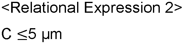
- The hot stamping component of claim 1, wherein the hot stamping component has a VDA bending angle of 60° or more.
- The hot stamping component of claim 1, wherein the hot stamping component has a yield strength (YP) of 900 MPa to 1300 MPa and an elongation (EL) of 4% to 10%.
- The hot stamping part of claim 1, wherein the hot stamping component has a microstructure with a martensite fraction of 90% or more.
- The hot stamping component of claim 1, further comprising a plating layer located on the inner oxide layer.
- The hot stamping component of claim 6, wherein a thickness of the plating layer is 10 µm to 30 µm.
- A method of manufacturing a hot stamping component, comprising:forming a blank by cutting a plated steel sheet having a plating layer formed on at least one surface of a base material; andheating the blank in a heating furnace having a plurality of sections with different temperature ranges,wherein the heating of the blank comprises:a multi-stage heating step of heating the blank stepwise; anda soaking step of heating the stepwise heated blank to a temperature of Ac1 to 910°C,wherein a hardness of the hot stamping component within a depth of 50 µm from a surface of the hot stamping component in a plate thickness direction of the hot stamping component and an average hardness of the hot stamping component satisfy Relational Expression 3.
 (In Relational Expression 3, A denotes the hardness (Hv(≤50 µm)) within the depth of 50 µm in the plate thickness direction of the hot stamping component, and B denotes the average hardness (Hv(avg.)) of the hot stamping component.)
 - The method of manufacturing a hot stamping component of claim 8, wherein a dew point of an annealing furnace of the base material is -15°C to +15°C.
- The method of manufacturing a hot stamping component of claim 8, wherein an annealing temperature of the base material is 750°C to 900°C.
- The method of manufacturing a hot stamping component of claim 8, further comprising:after the heating of the blank,transferring the heated blank;forming a molded body by pressing the transferred blank with a mold; andcooling the formed molded body.
- The method of manufacturing a hot stamping component of claim 11, wherein the hot stamping component further comprises:a decarburization layer formed on the base material; andan inner oxide layer formed on the decarburization layer.
- The method of manufacturing a hot stamping component of claim 12, wherein a depth of the inner oxide layer satisfies Relational Expression 4.

Applications Claiming Priority (2)
| Application Number | Priority Date | Filing Date | Title |
|---|---|---|---|
| KR1020220067234A KR102725864B1 (en) | 2022-05-31 | 2022-05-31 | Hot stamping component and method of manufacturing the same |
| PCT/KR2022/020564 WO2023234508A1 (en) | 2022-05-31 | 2022-12-16 | Hot stamping component and manufacturing method therefor |
Publications (1)
| Publication Number | Publication Date |
|---|---|
| EP4534704A1 true EP4534704A1 (en) | 2025-04-09 |
Family
ID=89025132
Family Applications (1)
| Application Number | Title | Priority Date | Filing Date |
|---|---|---|---|
| EP22945045.7A Pending EP4534704A1 (en) | 2022-05-31 | 2022-12-16 | Hot stamping component and manufacturing method therefor |
Country Status (6)
| Country | Link |
|---|---|
| US (1) | US20250092485A1 (en) |
| EP (1) | EP4534704A1 (en) |
| JP (1) | JP2025520173A (en) |
| KR (2) | KR102725864B1 (en) |
| CN (1) | CN119630818A (en) |
| WO (1) | WO2023234508A1 (en) |
Families Citing this family (1)
| Publication number | Priority date | Publication date | Assignee | Title |
|---|---|---|---|---|
| KR102725863B1 (en) * | 2022-05-31 | 2024-11-04 | 현대제철 주식회사 | Hot stamping component and method of manufacturing the same |
Family Cites Families (7)
| Publication number | Priority date | Publication date | Assignee | Title |
|---|---|---|---|---|
| JP2017066508A (en) * | 2015-10-02 | 2017-04-06 | 株式会社神戸製鋼所 | Galvanized steel sheet for hot pressing and manufacturing method of hot press-formed product |
| BR112019016858A2 (en) * | 2017-02-20 | 2020-04-07 | Nippon Steel Corporation | hot stamped body |
| KR102021200B1 (en) * | 2017-06-27 | 2019-09-11 | 현대제철 주식회사 | Hot stamping product and method of manufacturing the same |
| CN108588612B (en) * | 2018-04-28 | 2019-09-20 | 育材堂(苏州)材料科技有限公司 | Hot stamping components, pre-coated steel sheets for hot stamping and hot stamping process |
| KR102372480B1 (en) * | 2020-03-27 | 2022-03-08 | 현대제철 주식회사 | Tailor rolled blank, manufacturing method for hot stamping product using tailor rolled blank and hot stamping product manufactured using the same |
| KR102336757B1 (en) | 2020-04-21 | 2021-12-07 | 현대제철 주식회사 | Hot stamping product and method of manufacturing the same |
| KR102671433B1 (en) * | 2022-04-29 | 2024-05-31 | 현대제철 주식회사 | Hot stamping component and method of manufacturing the same |
-
2022
- 2022-05-31 KR KR1020220067234A patent/KR102725864B1/en active Active
- 2022-12-16 WO PCT/KR2022/020564 patent/WO2023234508A1/en not_active Ceased
- 2022-12-16 EP EP22945045.7A patent/EP4534704A1/en active Pending
- 2022-12-16 JP JP2024571106A patent/JP2025520173A/en active Pending
- 2022-12-16 CN CN202280098643.7A patent/CN119630818A/en active Pending
-
2024
- 2024-10-30 KR KR1020240151488A patent/KR102850228B1/en active Active
- 2024-12-02 US US18/965,209 patent/US20250092485A1/en active Pending
Also Published As
| Publication number | Publication date |
|---|---|
| JP2025520173A (en) | 2025-07-01 |
| WO2023234508A1 (en) | 2023-12-07 |
| KR102725864B1 (en) | 2024-11-05 |
| KR102850228B1 (en) | 2025-08-25 |
| KR20240161784A (en) | 2024-11-12 |
| KR20230166780A (en) | 2023-12-07 |
| US20250092485A1 (en) | 2025-03-20 |
| CN119630818A (en) | 2025-03-14 |
Similar Documents
| Publication | Publication Date | Title |
|---|---|---|
| JP2005126733A (en) | Steel sheet for hot pressing and automotive parts with excellent high-temperature workability | |
| CN111684091A (en) | High-strength cold-rolled steel sheet, high-strength plated steel sheet, and methods for producing these | |
| KR102310965B1 (en) | Hot stamping component and method of manufacturing the same | |
| KR20230082601A (en) | High-strength steel sheet having excellent formability and method for manufacturing thereof | |
| KR102775097B1 (en) | Hot stamping component and method of manufacturing the same | |
| KR20230087773A (en) | Steel sheet having excellent strength and ductility, and manufacturing method thereof | |
| KR102775098B1 (en) | Hot stamping component and method of manufacturing the same | |
| CN119731363A (en) | Plated steel sheet for thermoforming excellent in collision resistance, thermoformed part, and method for producing same | |
| US12054844B2 (en) | Blank for hot stamping, method for manufacturing the same, hot stamping component, and method for manufacturing the same | |
| KR102850228B1 (en) | Hot stamping component and method of manufacturing the same | |
| KR102850227B1 (en) | Hot stamping component and method of manufacturing the same | |
| KR20210080691A (en) | Hot rolled steel suitable for post heat treatable complex shaped parts with excellent hold expansion ratio and excellent yield ratio, parts, and menufacturing for the same | |
| KR102927088B1 (en) | Manufacturing method of steel sheet for hot stamping and manufactring method of hot stamping component | |
| EP4603617A1 (en) | Steel sheets and methods for manufacturing same | |
| KR20250105784A (en) | Method for manufacturing hot stamping component | |
| KR20250105865A (en) | Method for manufacturing hot stamping component | |
| KR20250032167A (en) | Manufacturing method of steel sheet for hot stamping and manufactring method of hot stamping component | |
| KR20250105889A (en) | Hot stamping component and method for manufacturing the same | |
| KR20250105861A (en) | Method for manufacturing steel sheet for hot stamping | |
| KR20250092492A (en) | Non-oriented electrical steel sheet and method for manufacturing the same | |
| JPH0784618B2 (en) | Method for producing cold-rolled steel sheet for deep drawing excellent in secondary processing brittleness resistance | |
| KR20240095963A (en) | Ultra high-strength cold rolled steel sheet having excellent elongation and hole expension ratio and method for manufacturing the same |
Legal Events
| Date | Code | Title | Description |
|---|---|---|---|
| STAA | Information on the status of an ep patent application or granted ep patent |
Free format text: STATUS: THE INTERNATIONAL PUBLICATION HAS BEEN MADE |
|
| PUAI | Public reference made under article 153(3) epc to a published international application that has entered the european phase |
Free format text: ORIGINAL CODE: 0009012 |
|
| STAA | Information on the status of an ep patent application or granted ep patent |
Free format text: STATUS: REQUEST FOR EXAMINATION WAS MADE |
|
| 17P | Request for examination filed |
Effective date: 20241202 |
|
| AK | Designated contracting states |
Kind code of ref document: A1 Designated state(s): AL AT BE BG CH CY CZ DE DK EE ES FI FR GB GR HR HU IE IS IT LI LT LU LV MC ME MK MT NL NO PL PT RO RS SE SI SK SM TR |
|
| DAV | Request for validation of the european patent (deleted) | ||
| DAX | Request for extension of the european patent (deleted) |