EP4534516A1 - Methane generation system - Google Patents
Methane generation system Download PDFInfo
- Publication number
- EP4534516A1 EP4534516A1 EP22944783.4A EP22944783A EP4534516A1 EP 4534516 A1 EP4534516 A1 EP 4534516A1 EP 22944783 A EP22944783 A EP 22944783A EP 4534516 A1 EP4534516 A1 EP 4534516A1
- Authority
- EP
- European Patent Office
- Prior art keywords
- heat exchange
- exchange section
- methane
- generation system
- heat
- Prior art date
- Legal status (The legal status is an assumption and is not a legal conclusion. Google has not performed a legal analysis and makes no representation as to the accuracy of the status listed.)
- Pending
Links
Images





Classifications
-
- C—CHEMISTRY; METALLURGY
- C10—PETROLEUM, GAS OR COKE INDUSTRIES; TECHNICAL GASES CONTAINING CARBON MONOXIDE; FUELS; LUBRICANTS; PEAT
- C10L—FUELS NOT OTHERWISE PROVIDED FOR; NATURAL GAS; SYNTHETIC NATURAL GAS OBTAINED BY PROCESSES NOT COVERED BY SUBCLASSES C10G OR C10K; LIQUIFIED PETROLEUM GAS; USE OF ADDITIVES TO FUELS OR FIRES; FIRE-LIGHTERS
- C10L3/00—Gaseous fuels; Natural gas; Synthetic natural gas obtained by processes not covered by subclass C10G, C10K; Liquefied petroleum gas
- C10L3/06—Natural gas; Synthetic natural gas obtained by processes not covered by C10G, C10K3/02 or C10K3/04
- C10L3/08—Production of synthetic natural gas
-
- C—CHEMISTRY; METALLURGY
- C25—ELECTROLYTIC OR ELECTROPHORETIC PROCESSES; APPARATUS THEREFOR
- C25B—ELECTROLYTIC OR ELECTROPHORETIC PROCESSES FOR THE PRODUCTION OF COMPOUNDS OR NON-METALS; APPARATUS THEREFOR
- C25B15/00—Operating or servicing cells
- C25B15/08—Supplying or removing reactants or electrolytes; Regeneration of electrolytes
- C25B15/081—Supplying products to non-electrochemical reactors that are combined with the electrochemical cell, e.g. Sabatier reactor
-
- B—PERFORMING OPERATIONS; TRANSPORTING
- B01—PHYSICAL OR CHEMICAL PROCESSES OR APPARATUS IN GENERAL
- B01J—CHEMICAL OR PHYSICAL PROCESSES, e.g. CATALYSIS OR COLLOID CHEMISTRY; THEIR RELEVANT APPARATUS
- B01J19/00—Chemical, physical or physico-chemical processes in general; Their relevant apparatus
- B01J19/0006—Controlling or regulating processes
- B01J19/0013—Controlling the temperature of the process
-
- B—PERFORMING OPERATIONS; TRANSPORTING
- B01—PHYSICAL OR CHEMICAL PROCESSES OR APPARATUS IN GENERAL
- B01J—CHEMICAL OR PHYSICAL PROCESSES, e.g. CATALYSIS OR COLLOID CHEMISTRY; THEIR RELEVANT APPARATUS
- B01J19/00—Chemical, physical or physico-chemical processes in general; Their relevant apparatus
- B01J19/24—Stationary reactors without moving elements inside
-
- C—CHEMISTRY; METALLURGY
- C25—ELECTROLYTIC OR ELECTROPHORETIC PROCESSES; APPARATUS THEREFOR
- C25B—ELECTROLYTIC OR ELECTROPHORETIC PROCESSES FOR THE PRODUCTION OF COMPOUNDS OR NON-METALS; APPARATUS THEREFOR
- C25B1/00—Electrolytic production of inorganic compounds or non-metals
- C25B1/01—Products
- C25B1/23—Carbon monoxide or syngas
-
- C—CHEMISTRY; METALLURGY
- C25—ELECTROLYTIC OR ELECTROPHORETIC PROCESSES; APPARATUS THEREFOR
- C25B—ELECTROLYTIC OR ELECTROPHORETIC PROCESSES FOR THE PRODUCTION OF COMPOUNDS OR NON-METALS; APPARATUS THEREFOR
- C25B15/00—Operating or servicing cells
- C25B15/02—Process control or regulation
- C25B15/021—Process control or regulation of heating or cooling
-
- C—CHEMISTRY; METALLURGY
- C25—ELECTROLYTIC OR ELECTROPHORETIC PROCESSES; APPARATUS THEREFOR
- C25B—ELECTROLYTIC OR ELECTROPHORETIC PROCESSES FOR THE PRODUCTION OF COMPOUNDS OR NON-METALS; APPARATUS THEREFOR
- C25B15/00—Operating or servicing cells
- C25B15/08—Supplying or removing reactants or electrolytes; Regeneration of electrolytes
-
- C—CHEMISTRY; METALLURGY
- C25—ELECTROLYTIC OR ELECTROPHORETIC PROCESSES; APPARATUS THEREFOR
- C25B—ELECTROLYTIC OR ELECTROPHORETIC PROCESSES FOR THE PRODUCTION OF COMPOUNDS OR NON-METALS; APPARATUS THEREFOR
- C25B15/00—Operating or servicing cells
- C25B15/08—Supplying or removing reactants or electrolytes; Regeneration of electrolytes
- C25B15/087—Recycling of electrolyte to electrochemical cell
-
- C—CHEMISTRY; METALLURGY
- C25—ELECTROLYTIC OR ELECTROPHORETIC PROCESSES; APPARATUS THEREFOR
- C25B—ELECTROLYTIC OR ELECTROPHORETIC PROCESSES FOR THE PRODUCTION OF COMPOUNDS OR NON-METALS; APPARATUS THEREFOR
- C25B9/00—Cells or assemblies of cells; Constructional parts of cells; Assemblies of constructional parts, e.g. electrode-diaphragm assemblies; Process-related cell features
- C25B9/17—Cells comprising dimensionally-stable non-movable electrodes; Assemblies of constructional parts thereof
- C25B9/19—Cells comprising dimensionally-stable non-movable electrodes; Assemblies of constructional parts thereof with diaphragms
-
- C—CHEMISTRY; METALLURGY
- C25—ELECTROLYTIC OR ELECTROPHORETIC PROCESSES; APPARATUS THEREFOR
- C25B—ELECTROLYTIC OR ELECTROPHORETIC PROCESSES FOR THE PRODUCTION OF COMPOUNDS OR NON-METALS; APPARATUS THEREFOR
- C25B9/00—Cells or assemblies of cells; Constructional parts of cells; Assemblies of constructional parts, e.g. electrode-diaphragm assemblies; Process-related cell features
- C25B9/60—Constructional parts of cells
- C25B9/67—Heating or cooling means
-
- B—PERFORMING OPERATIONS; TRANSPORTING
- B01—PHYSICAL OR CHEMICAL PROCESSES OR APPARATUS IN GENERAL
- B01J—CHEMICAL OR PHYSICAL PROCESSES, e.g. CATALYSIS OR COLLOID CHEMISTRY; THEIR RELEVANT APPARATUS
- B01J2219/00—Chemical, physical or physico-chemical processes in general; Their relevant apparatus
- B01J2219/00049—Controlling or regulating processes
- B01J2219/00051—Controlling the temperature
- B01J2219/00074—Controlling the temperature by indirect heating or cooling employing heat exchange fluids
- B01J2219/00087—Controlling the temperature by indirect heating or cooling employing heat exchange fluids with heat exchange elements outside the reactor
-
- B—PERFORMING OPERATIONS; TRANSPORTING
- B01—PHYSICAL OR CHEMICAL PROCESSES OR APPARATUS IN GENERAL
- B01J—CHEMICAL OR PHYSICAL PROCESSES, e.g. CATALYSIS OR COLLOID CHEMISTRY; THEIR RELEVANT APPARATUS
- B01J2219/00—Chemical, physical or physico-chemical processes in general; Their relevant apparatus
- B01J2219/00049—Controlling or regulating processes
- B01J2219/00051—Controlling the temperature
- B01J2219/00074—Controlling the temperature by indirect heating or cooling employing heat exchange fluids
- B01J2219/00087—Controlling the temperature by indirect heating or cooling employing heat exchange fluids with heat exchange elements outside the reactor
- B01J2219/00103—Controlling the temperature by indirect heating or cooling employing heat exchange fluids with heat exchange elements outside the reactor in a heat exchanger separate from the reactor
-
- B—PERFORMING OPERATIONS; TRANSPORTING
- B01—PHYSICAL OR CHEMICAL PROCESSES OR APPARATUS IN GENERAL
- B01J—CHEMICAL OR PHYSICAL PROCESSES, e.g. CATALYSIS OR COLLOID CHEMISTRY; THEIR RELEVANT APPARATUS
- B01J2219/00—Chemical, physical or physico-chemical processes in general; Their relevant apparatus
- B01J2219/00049—Controlling or regulating processes
- B01J2219/00051—Controlling the temperature
- B01J2219/00074—Controlling the temperature by indirect heating or cooling employing heat exchange fluids
- B01J2219/00105—Controlling the temperature by indirect heating or cooling employing heat exchange fluids part or all of the reactants being heated or cooled outside the reactor while recycling
- B01J2219/00108—Controlling the temperature by indirect heating or cooling employing heat exchange fluids part or all of the reactants being heated or cooled outside the reactor while recycling involving reactant vapours
-
- B—PERFORMING OPERATIONS; TRANSPORTING
- B01—PHYSICAL OR CHEMICAL PROCESSES OR APPARATUS IN GENERAL
- B01J—CHEMICAL OR PHYSICAL PROCESSES, e.g. CATALYSIS OR COLLOID CHEMISTRY; THEIR RELEVANT APPARATUS
- B01J2219/00—Chemical, physical or physico-chemical processes in general; Their relevant apparatus
- B01J2219/00049—Controlling or regulating processes
- B01J2219/00051—Controlling the temperature
- B01J2219/00074—Controlling the temperature by indirect heating or cooling employing heat exchange fluids
- B01J2219/00105—Controlling the temperature by indirect heating or cooling employing heat exchange fluids part or all of the reactants being heated or cooled outside the reactor while recycling
- B01J2219/0011—Controlling the temperature by indirect heating or cooling employing heat exchange fluids part or all of the reactants being heated or cooled outside the reactor while recycling involving reactant liquids
-
- B—PERFORMING OPERATIONS; TRANSPORTING
- B01—PHYSICAL OR CHEMICAL PROCESSES OR APPARATUS IN GENERAL
- B01J—CHEMICAL OR PHYSICAL PROCESSES, e.g. CATALYSIS OR COLLOID CHEMISTRY; THEIR RELEVANT APPARATUS
- B01J2219/00—Chemical, physical or physico-chemical processes in general; Their relevant apparatus
- B01J2219/00049—Controlling or regulating processes
- B01J2219/00051—Controlling the temperature
- B01J2219/00074—Controlling the temperature by indirect heating or cooling employing heat exchange fluids
- B01J2219/00117—Controlling the temperature by indirect heating or cooling employing heat exchange fluids with two or more reactions in heat exchange with each other, such as an endothermic reaction in heat exchange with an exothermic reaction
Definitions
- the present invention relates to a methane generation system.
- a methanation system that improves the conversion efficiency of water into methane by reusing the reaction heat of methane in a methanation reaction section in a water vapor generation section when producing methane using carbon dioxide, water, and electricity (Patent Document 1).
- Patent Document 1 Japanese Unexamined Patent Application, First Publication JP 2022- 22 978 A
- SOEC solid oxide electrolysis cell
- the present invention has been made in view of such a background and aims to effectively remove reaction heat from a methane reactor by thermally connecting an SOEC co-electrolysis device and a methanation reaction section (methane reactor) to each other and exchanging heat therebetween, thereby improving methane conversion efficiency by reusing the reaction heat in the SOEC co-electrolysis device and stabilizing the methane generation amount.
- One aspect of a methane generation system includes a water supply path that supplies water or water vapor, a carbon dioxide supply path that supplies carbon dioxide, a power supply path that supplies power, an SOEC co-electrolysis device to which the water supply path, the carbon dioxide supply path and the power supply path are connected, a methane reactor, a connection path that connects the SOEC co-electrolysis device and the methane reactor, and a first heat exchange section that performs heat exchange between the SOEC co-electrolysis device and the methane reactor.
- One aspect of a methane generation system includes a water supply path that supplies water or water vapor, a carbon dioxide supply path that supplies carbon dioxide, a power supply path that supplies power, an SOEC co-electrolysis device to which the water supply path, the carbon dioxide supply path and the power supply path are connected, a methane reactor, a connection path that connects the SOEC co-electrolysis device and the methane reactor, a first heat exchange section that performs heat exchange between the SOEC co-electrolysis device and the methane reactor, and a preliminary heat exchange section that heats the water or water vapor supplied through the water supply path to the SOEC co-electrolysis device by reaction heat of the methane reactor.
- the methane generation system 50 includes an SOEC co-electrolysis device 10, a methane reactor 11, and a first heat exchange section 20 thermally connected to both the SOEC co-electrolysis device 10 and the methane reactor 11.
- the SOEC co-electrolysis device 10, the first heat exchange section 20, and the methane reactor 11 are arranged side by side in a horizontal direction.
- a power supply path 1 for supplying power, a water supply path 2 for supplying water (H 2 O) or water vapor, and a carbon dioxide supply path 3 for supplying carbon dioxide (CO 2 ) are connected to the SOEC co-electrolysis device 10.
- the water or water vapor and the carbon dioxide which are supplied to the SOEC co-electrolysis device 10 from the water supply path 2 and the carbon dioxide supply path 3 are simultaneously electrolyzed in the SOEC co-electrolysis device 10 and converted into hydrogen and carbon monoxide.
- the water or water vapor flowing in the water supply path 2 and the carbon dioxide flowing in the carbon dioxide supply path 3 are moved to the SOEC co-electrolysis device 10 by obtaining kinetic energy from a fluid machine such as a pump or a blower (not shown).
- the hydrogen and carbon monoxide converted by the SOEC co-electrolysis device 10 through electrolysis are supplied to the methane reactor 11 via a connection path 4 that connects the SOEC co-electrolysis device 10 and the methane reactor 11.
- the hydrogen and carbon monoxide supplied to the methane reactor 11 are converted into methane (CH 4 ) and water in the methane reactor 11, and the methane is supplied to an external gas infrastructure 30 via a gas path 6.
- the reaction performed by the SOEC co-electrolysis device 10 is an endothermic reaction, heat is required for the reaction.
- the reaction performed in the methane reactor 11 is an exothermic reaction, heat is generated. Therefore, the heat generated in the exothermic reaction of the methane reactor 11 and the heat required for the SOEC co-electrolysis device 10 are exchanged through the first heat exchange section 20. In this way, by reusing the heat generated in the methane reactor 11 in the SOEC co-electrolysis device 10, the heat generated in the methane reactor 11 can be effectively removed. Additionally, since the heat required for the SOEC co-electrolysis device 10 can be supplied by the heat generated by the methane reactor 11, the methane conversion efficiency can be improved, and the methane generation amount can be stabilized.
- the power supplied to the SOEC co-electrolysis device 10 be renewable energy such as wind power or solar power.
- the power may be generated from a solid oxide fuel cell (SOFC).
- SOFC solid oxide fuel cell
- the SOFC is a device that uses hydrogen as a fuel, extracts electrons from oxygen taken in from the air, and generates an external current in a process where the oxygen (oxygen ion), from which the electrons have been extracted, reacts with hydrogen to produce water.
- the power supplied to the SOEC co-electrolysis device 10 does not necessarily have to be from renewable energy or SOFC.
- the carbon dioxide supplied to the SOEC co-electrolysis device 10 may be, for example, carbon dioxide discharged from the SOFC, carbon dioxide collected from the atmosphere by direct air capture (DAC), or carbon dioxide supplied from other carbon dioxide supply sources.
- DAC direct air capture
- the configuration of the first heat exchange section 20 is not particularly limited, and any known heat exchanger capable of performing heat exchange between the SOEC co-electrolysis device 10 and the methane reactor 11 may be used.
- known heat exchangers such as multi-tube heat exchangers, plate heat exchangers, coil heat exchangers, double pipes, or spiral heat exchangers can be used.
- Embodiment 2 of the present invention a methane generation system 51 according to Embodiment 2 of the present invention will be described with reference to FIG. 2 .
- the same components as those in Embodiment 1 shown in FIG. 1 are denoted by the same reference numerals, and their descriptions are omitted. Only the components that are different from those of Embodiment 1 will be described.
- the methane generation system 51 includes a heat transfer flow path 5 that supplies at least a part of the water or water vapor generated and released in the methane reactor 11 to the SOEC co-electrolysis device 10.
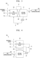
- Embodiment 3 of the present invention a methane generation system 52 according to Embodiment 3 of the present invention will be described with reference to FIG. 3 .
- the same components as those in Embodiment 2 shown in FIG. 2 are denoted by the same reference numerals, and their descriptions will be omitted. Only the components that are different from those in Embodiment 2 will be described.
- the methane generation system 52 includes a second heat exchange section 21 that exchanges heat with external exhaust heat in the heat transfer flow path 5.
- the water or water vapor flowing in the heat transfer flow path 5 can acquire a greater amount of heat through heat exchange with the external exhaust heat by the second heat exchange section 21, in addition to the heat generated in the methane reactor 11. Therefore, the required amount of heat in the SOEC co-electrolysis device 10 can be supplied by the heat generated in the methane reactor 11 and the external exhaust heat, thereby enhancing methane conversion efficiency and stabilizing methane generation amount.
- the external exhaust heat includes, in order from low temperature to high temperature, ventilation exhaust heat, air conditioning exhaust heat, hot water supply exhaust heat, boiler exhaust heat, and SOFC fuel cell exhaust heat.
- the ventilation exhaust heat is, for example, exhaust heat generated when air trapped inside a building, an office building or the like located on a site of a factory or the like where the methane generation system 52 is installed is exhausted to the outside.
- Air conditioning exhaust heat is, for example, exhaust heat from air conditioning systems installed in a building, an office building or the like located on a site of a factory or the like where the methane generation system 52 is installed.
- Hot water supply exhaust heat is, for example, exhaust heat from a hot water supply device provided in a building, an office building or the like located on a site of a factory or the like where the methane generation system 52 is installed.
- the SOFC fuel cell exhaust heat is exhaust heat generated during operation of the SOFC. Since the operating temperature of the SOFC is high temperature of approximately 1000 °C, it is possible to extract high-temperature exhaust heat.
- the SOEC co-electrolysis device 10 and the methane reactor 11 may be physically integrally formed.
- forming the SOEC co-electrolysis device 10 and the methane reactor 11 in a physically integral manner means that the SOEC co-electrolysis device 10 and the methane reactor 11 may be formed as one member using the same member.
- the SOEC co-electrolysis device 10 and the methane reactor 11, formed of different members may be integrated by welding.
- the SOEC co-electrolysis device 10 and the methane reactor 11, formed of different members may be integrated through fastening members such as bolts and nuts.
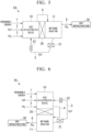
- Embodiment 4 of the present invention a methane generation system 53 according to Embodiment 4 of the present invention will be described with reference to FIG. 4 .
- the same components as those in Embodiment 3 shown in FIG. 3 are denoted by the same reference numerals, and their descriptions will be omitted. Only the components that are different from those in Embodiment 3 will be described.
- the SOEC co-electrolysis device 10 is provided at a position higher than the methane reactor 11. That is, the methane generation system 52 shown in FIG. 3 is a configuration rotated clockwise such that the SOEC co-electrolysis device 10 is positioned above the methane reactor 11. In this case, the SOEC co-electrolysis device 10, the first heat exchange section 20, and the methane reactor 11 are arranged in a vertical direction. As described above, a configuration in which the SOEC co-electrolysis device 10 is provided above the methane reactor 11 may be referred to as a vertical arrangement. Note that the SOEC co-electrolysis device 10 may be provided to directly face the methane reactor 11 without the first heat exchange section 20 interposed therebetween at a position higher than the methane reactor 11.
- the SOEC co-electrolysis device 10 is provided at a position higher than the methane reactor 11. Therefore, the temperature difference of the fluid present in the vicinity of the heat transfer surface between the SOEC co-electrolysis device 10 and the methane reactor 11 can be increased. Therefore, since the heat exchange performance between the SOEC co-electrolysis device 10 and the methane reactor 11 can be improved, the methane conversion efficiency can be enhanced.
- Embodiment 5 of the present invention a methane generation system 54 according to Embodiment 5 of the present invention will be described with reference to FIG. 5 .
- the same components as those in Embodiment 3 shown in FIG. 3 are denoted by the same reference numerals, and their descriptions will be omitted. Only the components that are different from those in Embodiment 3 will be described.
- the methane generation system 54 includes a first heater 22 in addition to the second heat exchange section 21 in the heat transfer flow path 5.
- the first heater 22 is provided downstream of the second heat exchange section 21 in the flow direction of the water or water vapor flowing through the heat transfer flow path 5.
- the water or water vapor flowing in the heat transfer flow path 5 can obtain the heat generated in the methane reactor 11, the heat obtained through heat exchange with the external exhaust heat by the second heat exchange section 21, and the heat obtained by the first heater 22. Therefore, the heat required for the SOEC co-electrolysis device 10 can be supplied by the heat generated in the methane reactor 11, the external exhaust heat, and the heat obtained from the first heater 22. Therefore, the methane conversion efficiency can be improved, and the methane generation amount can be stabilized.
- Embodiment 6 of the present invention a methane generation system 55 according to Embodiment 6 of the present invention will be described with reference to FIG. 6 .
- the same components as those in Embodiment 5 shown in FIG. 5 are denoted by the same reference numerals, and their descriptions are omitted. Only the components that are different from those in Embodiment 5 will be described.
- the methane generation system 56 includes at least any one of a third heat exchange section 23 that exchanges heat with external ventilation exhaust heat, a fourth heat exchange section 24 that exchanges heat with external air conditioning exhaust heat, a fifth heat exchange section 25 that exchanges heat with external hot water supply exhaust heat, a sixth heat exchange section 26 that exchanges heat with external boiler exhaust heat, or a seventh heat exchange section 27 that exchanges heat with external SOFC fuel cell exhaust heat, all of which heat water or water vapor flowing through the heat transfer flow path 5, in the second heat exchange section 21.
- the third heat exchange section 23, the fourth heat exchange section 24, the fifth heat exchange section 25, the sixth heat exchange section 26, and the seventh heat exchange section 27 are disposed upstream in the flow direction of the water or water vapor flowing through the heat transfer flow path 5, with the lower temperature heat exchange sections positioned further upstream.
- water or water vapor flowing in the heat transfer flow path 5 undergoes heat exchange sequentially from the heat exchange section with a lower temperature to the heat exchange section with a higher temperature. Therefore, even an external heat source with a low temperature can be effectively used as a heat source for heating water or water vapor flowing in the heat transfer flow path 5.
- all of the third heat exchange section 23, the fourth heat exchange section 24, the fifth heat exchange section 25, the sixth heat exchange section 26, and the seventh heat exchange section 27 are provided, but only at least one or more of these need be provided.
- the effect of increasing the heat of the water or water vapor supplied to the SOEC co-electrolysis device 10 is maximized.
- Embodiment 8 of the present invention a methane generation system 57 according to Embodiment 8 of the present invention will be described with reference to FIG. 8 .
- the same components as those in Embodiment 7 shown in FIG. 7 are denoted by the same reference numerals, and their descriptions will be omitted. Only the components that are different from those in Embodiment 7 will be described.
- the methane generation system 57 has a configuration in which the methane generation system 56 of Embodiment 7 shown in FIG. 7 is arranged vertically, with the SOEC co-electrolysis device 10 provided above the methane reactor 11. Therefore, since the SOEC co-electrolysis device 10 is provided at a position higher than the methane reactor 11, the temperature difference of the fluid present in the vicinity of the heat transfer surface between the SOEC co-electrolysis device 10 and the methane reactor 11 can be increased. Therefore, in addition to the effect obtained by the methane generation system 56 according to Embodiment 7 shown in FIG. 7 , the heat exchange performance between the SOEC co-electrolysis device 10 and the methane reactor 11 can be improved, thereby enhancing the methane conversion efficiency and stabilizing the methane generation amount.
- Embodiment 9 of the present invention a methane generation system 58 according to Embodiment 9 of the present invention will be described with reference to FIG. 9 .
- the same components as those in Embodiment 7 shown in FIG. 7 are denoted by the same reference numerals, and their descriptions will be omitted. Only the components that are different from those in Embodiment 7 will be described.
- the methane generation system 58 includes a first preliminary heat exchange section 28, where water or water vapor flowing through the water supply path 2 is heated by the reaction heat of the methane reactor 11, in the methane generation system 56 of Embodiment 7 shown in FIG. 7 .
- FIG. 9A shows a configuration of a methane generation system 58A according to Embodiment 9A of the present invention.
- the methane generation system 58A according to Embodiment 9A has a configuration in which the heat transfer flow path 5 is removed from the methane generation system 58 according to Embodiment 9 shown in FIG. 9 . That is, in the methane generation system 58 according to Embodiment 9, the configuration does not include the heat transfer flow path 5 and includes only the first preliminary heat exchange section 28. In this case, the water supply path 2, which includes the first preliminary heat exchange section 28, can also be considered as one of the heat transfer flow path.
- This configuration can promote electrolysis in the SOEC co-electrolysis device 10 and improve the methane conversion efficiency of the methane reactor 11. Note that, also in the configuration including the first preliminary heat exchange section 28, which will be described in the following embodiments, the configuration without the heat transfer flow path 5 can also be adopted.
- the methane generation system 59 has a configuration in which the methane generation system 58 of Embodiment 9 shown in FIG. 9 is arranged vertically, with the SOEC co-electrolysis device 10 provided above the methane reactor 11. Therefore, since the SOEC co-electrolysis device 10 is provided at a position higher than the methane reactor 11, the temperature difference of the fluid present in the vicinity of the heat transfer surface between the SOEC co-electrolysis device 10 and the methane reactor 11 can be increased. Accordingly, in addition to the effect obtained by the methane generation system 58 according to Embodiment 9 shown in FIG. 9 , the heat exchange performance between the SOEC co-electrolysis device 10 and the methane reactor 11 can be improved, thereby enhancing the methane conversion efficiency and stabilizing the methane generation amount.
- Embodiment 11 of the present invention a methane generation system 60 according to Embodiment 11 of the present invention will be described with reference to FIG. 11 .
- the same components as those in Embodiment 9 shown in FIG. 9 are denoted by the same reference numerals, and their descriptions will be omitted. Only the components that are different from those in Embodiment 6 will be described.
- the eighth heat exchange section 23a, the ninth heat exchange section 24a, the tenth heat exchange section 25a, the eleventh heat exchange section 26a, and the twelfth heat exchange section 27a are provided in the water supply path 2 such that the heat exchange section with a lower temperature is disposed upstream with respect to the flow direction of the water or water vapor flowing through the water supply path 2.
- the eighth heat exchange section 23a having the lowest temperature is provided the most upstream with respect to the flow direction of the water or water vapor flowing through the water supply path 2
- the twelfth heat exchange section 27a having the highest temperature is provided the most downstream with respect to the flow direction of the water or water vapor flowing through the water supply path 2.
- the ninth heat exchange section 24a, the tenth heat exchange section 25a, and the eleventh heat exchange section 26a are provided between the eighth heat exchange section 23a and the twelfth heat exchange section 27a in order from the upstream side with respect to the flow direction of the water or water vapor flowing through the water supply path 2.
- the water or water vapor flowing in the water supply path 2 is heated by at least any one of the eighth heat exchange section 23a, the ninth heat exchange section 24a, the tenth heat exchange section 25a, the eleventh heat exchange section 26a, or the twelfth heat exchange section 27a, in addition to the first preliminary heat exchange section 28. Therefore, since the amount of heat of the water or water vapor supplied to the SOEC co-electrolysis device 10 is further increased, it is possible to further promote the electrolysis in the SOEC co-electrolysis device 10.
- Embodiment 12 of the present invention a methane generation system 61 according to Embodiment 12 of the present invention will be described with reference to FIG. 12 .
- the same components as those of Embodiment 11 shown in FIG. 11 are denoted by the same reference numerals, and the description thereof will be omitted. Only the components different from those of Embodiment 8 will be described.
- the methane generation system 61 has a configuration in which the methane generation system 60 of Embodiment 11 shown in FIG. 11 is arranged vertically, with the SOEC co-electrolysis device 10 provided above the methane reactor 11. Therefore, since the SOEC co-electrolysis device 10 is provided at a position higher than the methane reactor 11, the temperature difference of the fluid present in the vicinity of the heat transfer surface between the SOEC co-electrolysis device 10 and the methane reactor 11 can be increased. Therefore, in addition to the effects obtained by the methane generation system 60 according to Embodiment 11 shown in FIG. 11 , the heat exchange performance between the SOEC co-electrolysis device 10 and the methane reactor 11 can be improved, thereby enhancing the methane conversion efficiency and stabilizing the methane generation amount.
- Embodiment 13 of the present invention a methane generation system 62 according to Embodiment 13 of the present invention will be described with reference to FIG. 13 .
- the same components as those in Embodiment 7 shown in FIG. 7 are denoted by the same reference numerals, and their descriptions will be omitted. Only the components that are different from those in Embodiment 7 will be described.
- the methane generation system 62 includes a second preliminary heat exchange section 29, where the carbon dioxide flowing through the carbon dioxide supply path 3 is heated by the reaction heat of the methane reactor 11, in the methane generation system 56 of Embodiment 7 shown in FIG. 7 .
- Embodiment 14 of the present invention a methane generation system 63 according to Embodiment 14 of the present invention will be described with reference to FIG. 14 .
- the same components as those in Embodiment 13 shown in FIG. 13 are denoted by the same reference numerals, and their descriptions are omitted. Only the components that are different from those of Embodiment 9 will be described.
- Embodiment 15 of the present invention a methane generation system 64 according to Embodiment 15 of the present invention will be described with reference to FIG. 15 .
- the same components as those in Embodiment 7 shown in FIG. 7 are denoted by the same reference numerals, and their descriptions will be omitted. Only the components that are different from those in Embodiment 7 will be described.
- the methane generation system 64 includes a third preliminary heat exchange section 35 where the water or water vapor flowing in the water supply path 2 and carbon dioxide flowing in the carbon dioxide supply path 3 are heated by the reaction heat of the methane reactor 11.
- the methane generation system 64 configured as such, since the amount of heat of the water or water vapor and the carbon dioxide supplied to the SOEC co-electrolysis device 10 is increased, the electrolysis in the SOEC co-electrolysis device 10 can be promoted. Further, the methane reactor 11 performs heat exchange with a plurality of fluids, including water or water vapor and carbon dioxide. Therefore, more heat generated from the methane reactor 11 can be dissipated, and the methane conversion efficiency can be improved.
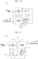
- Embodiment 16 of the present invention a methane generation system 65 according to Embodiment 16 of the present invention will be described with reference to FIG. 16 .
- the same components as those in Embodiment 15 shown in FIG. 15 are denoted by the same reference numerals, and their descriptions will be omitted. Only the components that are different from those in Embodiment 15 will be described.
- the methane generation system 65 has a configuration in which the methane generation system 64 of Embodiment 15 shown in FIG. 15 is arranged vertically, with the SOEC co-electrolysis device 10 provided above the methane reactor 11. Therefore, since the SOEC co-electrolysis device 10 is provided at a position higher than the methane reactor 11, the temperature difference of the fluid present in the vicinity of the heat transfer surface between the SOEC co-electrolysis device 10 and the methane reactor 11 can be increased. Therefore, in addition to the effect obtained by the methane generation system 64 according to Embodiment 15 shown in FIG. 15 , the heat exchange performance between the SOEC co-electrolysis device 10 and the methane reactor 11 can be improved, thereby enhancing the methane conversion efficiency and stabilizing the methane generation amount.
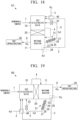
- Embodiment 17 of the present invention a methane generation system 66 according to Embodiment 17 of the present invention will be described with reference to FIG. 17 .
- the same components as those in Embodiment 9 shown in FIG. 9 are denoted by the same reference numerals, and their descriptions will be omitted. Only the components different from those in Embodiment 9 will be described.
- an ejector 40 which uses water or water vapor flowing through the water supply path 2 as a driving fluid, is provided in the water supply path 2, and the carbon dioxide supply path 3 is connected to the SOEC co-electrolysis device 10 via the ejector 40.
- the carbon dioxide flowing through the carbon dioxide supply path 3 is drawn into the flow of water or water vapor, which serves as the driving fluid of the ejector 40. That is, by using a fluid machine such as a blower (not shown) which moves the carbon dioxide flowing in the carbon dioxide supply path 3 to the SOEC co-electrolysis device 10 in combination with the ejector 40, it is possible to reduce the power consumption of the fluid machine. In this way, the energy required for the operation of the methane generation system 66 can be reduced.
- a fluid machine such as a blower (not shown) which moves the carbon dioxide flowing in the carbon dioxide supply path 3 to the SOEC co-electrolysis device 10 in combination with the ejector 40
- Embodiment 18 of the present invention a methane generation system 67 according to Embodiment 18 of the present invention will be described with reference to FIG. 18 .
- the same components as those in Embodiment 17 shown in FIG. 17 are denoted by the same reference numerals, and their descriptions will be omitted. Only the components that are different from those in Embodiment 17 will be described.
- the methane generation system 67 has a configuration in which the methane generation system 66 of Embodiment 17 shown in FIG. 17 is arranged vertically, with the SOEC co-electrolysis device 10 provided above the methane reactor 11. Therefore, since the SOEC co-electrolysis device 10 is provided at a position higher than the methane reactor 11, the temperature difference of the fluid present in the vicinity of the heat transfer surface between the SOEC co-electrolysis device 10 and the methane reactor 11 can be increased. Therefore, in addition to the effects obtained by the methane generation system 66 according to Embodiment 17 shown in FIG. 17 , the heat exchange performance between the SOEC co-electrolysis device 10 and the methane reactor 11 can be improved, thereby enhancing the methane conversion efficiency and stabilizing the methane generation amount.
- Embodiment 19 of the present invention a methane generation system 68 according to Embodiment 19 of the present invention will be described with reference to FIG. 19 .
- the same components as those in Embodiment 13 shown in FIG. 13 are denoted by the same reference numerals, and their descriptions will be omitted. Only the components that are different from those in Embodiment 13 will be described.
- the ejector 40 which uses the carbon dioxide flowing through the carbon dioxide supply path 3 as the driving fluid, is provided in the carbon dioxide supply path 3, in the methane generation system 62 of Embodiment 13 shown in FIG. 13 .
- the water supply path 2 is connected to the SOEC co-electrolysis device 10 via the ejector 40.
- water or water vapor flowing through the water supply path 2 is drawn into the flow of carbon dioxide, which is the driving fluid of the ejector 40. That is, by using a fluid machine such as a pump or blower (not shown) that moves the water or water vapor flowing in the water supply path 2 to the SOEC co-electrolysis device 10 in combination with the ejector 40, it is possible to reduce the power consumption of the fluid machine. In this way, the energy required for the operation of the methane generation system 68 can be reduced.
- a fluid machine such as a pump or blower (not shown) that moves the water or water vapor flowing in the water supply path 2 to the SOEC co-electrolysis device 10 in combination with the ejector 40.
- the methane generation system 69 has a configuration in which the methane generation system 68 of Embodiment 19 shown in FIG. 19 is arranged vertically, with the SOEC co-electrolysis device 10 provided above the methane reactor 11. Therefore, since the SOEC co-electrolysis device 10 is provided at a position higher than the methane reactor 11, the temperature difference of the fluid present in the vicinity of the heat transfer surface between the SOEC co-electrolysis device 10 and the methane reactor 11 can be increased. Therefore, in addition to the effects obtained by the methane generation system 68 according to Embodiment 19 shown in FIG. 19 , the heat exchange performance between the SOEC co-electrolysis device 10 and the methane reactor 11 can be improved, thereby enhancing the methane conversion efficiency and stabilizing the methane generation amount.
- Embodiment 21 of the present invention a methane generation system 70 according to Embodiment 21 of the present invention will be described with reference to FIG. 21 .
- the same components as those in Embodiment 19 shown in FIG. 19 are denoted by the same reference numerals, and their descriptions are omitted. Only the components that are different from those of Embodiment 19 will be described.
- the methane generation system 70 includes at least any one of a thirteenth heat exchange section 23b that performs heat exchange with external ventilation exhaust heat, a fourteenth heat exchange section 24b that performs heat exchange with external air conditioning exhaust heat, a fifteenth heat exchange section 25b that performs heat exchange with external hot water supply exhaust heat, a sixteenth heat exchange section 26b that performs heat exchange with external boiler exhaust heat, or a seventeenth heat exchange section 27b that performs heat exchange with external SOFC fuel cell exhaust heat, upstream of the ejector 40 with respect to the flow direction of water or water vapor flowing through the water supply path 2 in the methane generation system 68 of Embodiment 19 shown in FIG. 19 .
- the thirteenth heat exchange section 23b, the fourteenth heat exchange section 24b, the fifteenth heat exchange section 25b, the sixteenth heat exchange section 26b, and the seventeenth heat exchange section 27b are provided on the water supply path 2 such that the heat exchange section with a lower temperature is disposed on the upstream side with respect to the flow direction of the water or water vapor flowing through the water supply path 2.
- the thirteenth heat exchange section 23b having the lowest temperature is provided the most upstream with respect to the flow direction of the water or water vapor flowing through the water supply path 2
- the seventeenth heat exchange section 27b having the highest temperature is provided the most downstream with respect to the flow direction of the water or water vapor flowing through the water supply path 2.
- the fourteenth heat exchange section 24b, the fifteenth heat exchange section 25b, and the sixteenth heat exchange section 26b are provided between the thirteenth heat exchange section 23b and the seventeenth heat exchange section 27b in order from the upstream side with respect to the flow direction of the water or water vapor flowing through the water supply path 2.
- the water or water vapor flowing through the water supply path 2 before being suctioned into the ejector 40 is heated by at least any one of the thirteenth heat exchange section 23b, the fourteenth heat exchange section 24b, the fifteenth heat exchange section 25b, the sixteenth heat exchange section 26b, or the seventeenth heat exchange section 27b. Therefore, the water or water vapor flowing through the water supply path 2, which is suctioned by the ejector 40, can be converted into a gas state.
- the suctioning effect of the ejector 40 can be increased. That is, by using a fluid machine such as a pump or blower (not shown) that moves the water or water vapor flowing in the water supply path 2 to the SOEC co-electrolysis device 10 in combination with the ejector 40, it is possible to reduce the power consumption of the fluid machine. In this way, the energy required for the operation of the methane generation system 70 can be reduced.
- a fluid machine such as a pump or blower (not shown) that moves the water or water vapor flowing in the water supply path 2 to the SOEC co-electrolysis device 10 in combination with the ejector 40, it is possible to reduce the power consumption of the fluid machine. In this way, the energy required for the operation of the methane generation system 70 can be reduced.
- Embodiment 22 of the present invention a methane generation system 71 according to Embodiment 22 of the present invention will be described with reference to FIG. 22 .
- the same components as those in Embodiment 21 shown in FIG. 21 are denoted by the same reference numerals, and their descriptions will be omitted. Only the components that are different from those in Embodiment 21 will be described.
- the methane generation system 71 has a configuration in which the methane generation system 70 of Embodiment 21 shown in FIG. 21 is arranged vertically, with the SOEC co-electrolysis device 10 provided above the methane reactor 11. Therefore, since the SOEC co-electrolysis device 10 is provided at a position higher than the methane reactor 11, the temperature difference of the fluid present in the vicinity of the heat transfer surface between the SOEC co-electrolysis device 10 and the methane reactor 11 can be increased. Therefore, in addition to the effects obtained by the methane generation system 70 according to Embodiment 21 shown in FIG. 21 , the heat exchange performance between the SOEC co-electrolysis device 10 and the methane reactor 11 can be improved, thereby enhancing the methane conversion efficiency and stabilizing the methane generation amount.
- Embodiment 23 of the present invention a methane generation system 72 according to Embodiment 23 of the present invention will be described with reference to FIG. 23 .
- the same components as those in Embodiment 9 shown in FIG. 9 are denoted by the same reference numerals, and their descriptions will be omitted. Only the components different from those in Embodiment 9 will be described.
- the methane generation system 72 includes at least any one of an eighth heat exchange section 23a that performs heat exchange with external ventilation exhaust heat, a ninth heat exchange section 24a that performs heat exchange with external air conditioning exhaust heat, a tenth heat exchange section 25a that performs heat exchange with external hot water supply exhaust heat, an eleventh heat exchange section 26a that performs heat exchange with external boiler exhaust heat, or a twelfth heat exchange section 27a that performs heat exchange with external SOFC fuel cell exhaust heat, all of which heat water or water vapor flowing in the water supply path 2 upstream of the first preliminary heat exchange section 28, with respect to the flow direction of the water or water vapor flowing in the water supply path 2, in the methane generation system 58 of Embodiment 9 shown in FIG. 9 .
- the eighth heat exchange section 23a, the ninth heat exchange section 24a, the tenth heat exchange section 25a, the eleventh heat exchange section 26a, and the twelfth heat exchange section 27a are provided in the water supply path 2 such that the heat exchange section with a lower temperature is disposed upstream with respect to the flow direction of the water or water vapor flowing through the water supply path 2.
- the eighth heat exchange section 23a having the lowest temperature is provided the most upstream with respect to the flow direction of the water or water vapor flowing through the water supply path 2
- the twelfth heat exchange section 27a having the highest temperature is provided the most downstream with respect to the flow direction of the water or water vapor flowing through the water supply path 2.
- the ninth heat exchange section 24a, the tenth heat exchange section 25a, and the eleventh heat exchange section 26a are provided between the eighth heat exchange section 23a and the twelfth heat exchange section 27a in order from the upstream side with respect to the flow direction of the water or water vapor flowing through the water supply path 2.
- a second heater 22a that heats the water or water vapor flowing in the water supply path 2 is provided downstream of the first preliminary heat exchange section 28.
- the water or water vapor flowing in the water supply path 2 is heated by at least any one of the eighth heat exchange section 23a, the ninth heat exchange section 24a, the tenth heat exchange section 25a, the eleventh heat exchange section 26a, the twelfth heat exchange section 27a, and the second heater 22a, in addition to the heat generated by the methane reactor 11. Therefore, the heat of the water or water vapor supplied to the SOEC co-electrolysis device 10 is increased, and it is possible to promote electrolysis in the SOEC co-electrolysis device 10. Further, the methane conversion efficiency can be improved by dissipating the heat generated from the methane reactor 11.
- Embodiment 24 of the present invention a methane generation system 73 according to Embodiment 24 of the present invention will be described with reference to FIG. 24 .
- the same components as those in Embodiment 23 shown in FIG. 23 are denoted by the same reference numerals, and their descriptions are omitted. Only the components that are different from those of Embodiment 23 will be described.
- the methane generation system 73 has a configuration in which the methane generation system 72 of Embodiment 23 shown in FIG. 23 is arranged vertically, with the SOEC co-electrolysis device 10 provided above the methane reactor 11. Therefore, since the SOEC co-electrolysis device 10 is provided at a position higher than the methane reactor 11, the temperature difference of the fluid present in the vicinity of the heat transfer surface between the SOEC co-electrolysis device 10 and the methane reactor 11 can be increased. Therefore, in addition to the effects obtained by the methane generation system 72 according to Embodiment 23 shown in FIG. 23 , the heat exchange performance between the SOEC co-electrolysis device 10 and the methane reactor 11 can be improved, thereby enhancing the methane conversion efficiency and stabilizing the methane generation amount.
- Embodiment 25 of the present invention a methane generation system 74 according to Embodiment 25 of the present invention will be described with reference to FIG. 25 .
- the same components as those in Embodiment 23 shown in FIG. 23 are denoted by the same reference numerals, and their descriptions are omitted. Only the components that are different from those of Embodiment 23 will be described.
- the twelfth heat exchange section 27a is provided downstream of the first preliminary heat exchange section 28 with respect to the flow direction of the water or water vapor flowing through the water supply path 2. Therefore, even if the twelfth heat exchange section 27a, which has the highest temperature among the eighth heat exchange section 23a to twelfth heat exchange section 27a, heats the water or water vapor flowing in the water supply path 2 at a temperature higher than that of the methane reactor 11, the heating of both the methane reactor 11 and the twelfth heat exchange section 27a can be effectively utilized.
- Embodiment 26 of the present invention a methane generation system 75 according to Embodiment 26 of the present invention will be described with reference to FIG. 26 .
- the same components as those in Embodiment 25 shown in FIG. 25 are denoted by the same reference numerals, and their description will be omitted. Only the components that are different from those in Embodiment 25 will be described.
- the methane generation system 75 has a configuration in which the methane generation system 74 of Embodiment 25 shown in FIG. 25 is arranged vertically, with the SOEC co-electrolysis device 10 provided above the methane reactor 11. Therefore, since the SOEC co-electrolysis device 10 is provided at a position higher than the methane reactor 11, the temperature difference of the fluid present in the vicinity of the heat transfer surface between the SOEC co-electrolysis device 10 and the methane reactor 11 can be increased. Therefore, in addition to the effect obtained by the methane generation system 74 according to Embodiment 25 shown in FIG. 25 , the heat exchange performance between the SOEC co-electrolysis device 10 and the methane reactor 11 can be improved, thereby enhancing the methane conversion efficiency and stabilizing the methane generation amount.
- the carbon dioxide supply path 3 in the carbon dioxide supply path 3, at least any one of the eighth heat exchange section 23a that performs heat exchange with external ventilation exhaust heat, the ninth heat exchange section 24a that performs heat exchange with external air conditioning exhaust heat, the tenth heat exchange section 25a that performs heat exchange with external hot water supply exhaust heat, the eleventh heat exchange section 26a that performs heat exchange with external boiler exhaust heat, or the twelfth heat exchange section 27a that performs heat exchange with external SOFC fuel cell exhaust heat may be provided downstream of the second preliminary heat exchange section 29 in the flow direction of the carbon dioxide flowing through the carbon dioxide supply path 3.
- the carbon dioxide supply path 3 may further include the second heater 22a downstream of the twelfth heat exchange section 27a in the flow direction of the carbon dioxide flowing through the carbon dioxide supply path 3.
- the carbon dioxide flowing through the carbon dioxide supply path 3 is heated by at least any one of the eighth heat exchange section 23a, the ninth heat exchange section 24a, the tenth heat exchange section 25a, the eleventh heat exchange section 26a, or the twelfth heat exchange section 27a in addition to the second preliminary heat exchange section 29. Therefore, since the amount of heat of the carbon dioxide supplied to the SOEC co-electrolysis device 10 is further increased, it is possible to further promote the electrolysis in the SOEC co-electrolysis device 10.
- the methane generation system 62 of Embodiment 13 and the methane generation system 63 of Embodiment 14 in the carbon dioxide supply path 3, at least any one of the eighth heat exchange section 23a that performs heat exchange with external ventilation exhaust heat, the ninth heat exchange section 24a that performs heat exchange with external air conditioning exhaust heat, the tenth heat exchange section 25a that performs heat exchange with external hot water supply exhaust heat, the eleventh heat exchange section 26a that performs heat exchange with external boiler exhaust heat, or the twelfth heat exchange section 27a that performs heat exchange with external SOFC fuel cell exhaust heat may be provided upstream of the second preliminary heat exchange section 29 in the flow direction of the carbon dioxide flowing through the carbon dioxide supply path 3.
- the second heater 22a may be further provided downstream of the second preliminary heat exchange section 29 in the flow direction of the carbon dioxide flowing in the carbon dioxide supply path 3.
- the carbon dioxide flowing through the carbon dioxide supply path 3 is heated by at least any one of the eighth heat exchange section 23a, the ninth heat exchange section 24a, the tenth heat exchange section 25a, the eleventh heat exchange section 26a, or the twelfth heat exchange section 27a in addition to the second preliminary heat exchange section 29. Therefore, since the amount of heat of the carbon dioxide supplied to the SOEC co-electrolysis device 10 is further increased, it is possible to further promote the electrolysis in the SOEC co-electrolysis device 10.
- At least any one of the eighth heat exchange section 23a that performs heat exchange with external ventilation exhaust heat, the ninth heat exchange section 24a that performs heat exchange with external air conditioning exhaust heat, the tenth heat exchange section 25a that performs heat exchange with external hot water supply exhaust heat, the eleventh heat exchange section 26a that performs heat exchange with external boiler exhaust heat, or the twelfth heat exchange section 27a that performs heat exchange with external SOFC fuel cell exhaust heat may be provided upstream or downstream of the second preliminary heat exchange section 29 in the carbon dioxide supply path 3 in the flow direction of the carbon dioxide flowing through the carbon dioxide supply path 3.
- the carbon dioxide flowing in the carbon dioxide supply path 3 is heated by at least any one of the eighth heat exchange section 23a, the ninth heat exchange section 24a, the tenth heat exchange section 25a, the eleventh heat exchange section 26a, or the twelfth heat exchange section 27a, in addition to the second preliminary heat exchange section 29. Therefore, since the amount of heat of the carbon dioxide supplied to the SOEC co-electrolysis device 10 is further increased, it is possible to further promote the electrolysis in the SOEC co-electrolysis device 10. This effect is greatest when all of the eighth heat exchange section 23a, the ninth heat exchange section 24a, the tenth heat exchange section 25a, the eleventh heat exchange section 26a, and the twelfth heat exchange section 27a are provided.
- Embodiment 4 a configuration has been described in which the SOEC co-electrolysis device 10 is arranged vertically and provided at a higher position than the methane reactor 11.
- the methane generation system 50 of Embodiment 1 and the methane generation system 51 of Embodiment 2 may also be configured such that the SOEC co-electrolysis device 10 is arranged vertically and provided at a higher position than the methane reactor 11. In this case as well, the same effect as in Embodiment 4 can be obtained.
- the SOEC co-electrolysis device 10 and the methane reactor 11 may be physically integrally formed with each other, the SOEC co-electrolysis device 10 and the methane reactor 11 may be physically integrally formed with each other in other Embodiments too.
Landscapes
- Chemical & Material Sciences (AREA)
- Organic Chemistry (AREA)
- Chemical Kinetics & Catalysis (AREA)
- Engineering & Computer Science (AREA)
- Electrochemistry (AREA)
- Materials Engineering (AREA)
- Metallurgy (AREA)
- Oil, Petroleum & Natural Gas (AREA)
- Sustainable Development (AREA)
- Life Sciences & Earth Sciences (AREA)
- Automation & Control Theory (AREA)
- Inorganic Chemistry (AREA)
- General Chemical & Material Sciences (AREA)
- Fuel Cell (AREA)
- Electrolytic Production Of Non-Metals, Compounds, Apparatuses Therefor (AREA)
- Organic Low-Molecular-Weight Compounds And Preparation Thereof (AREA)
Abstract
Description
- The present invention relates to a methane generation system.
- In the related art, a methanation system is known that improves the conversion efficiency of water into methane by reusing the reaction heat of methane in a methanation reaction section in a water vapor generation section when producing methane using carbon dioxide, water, and electricity (Patent Document 1).
- Patent Document 1: Japanese Unexamined Patent Application, First Publication
JP 2022- 22 978 A - In a methanation system using a solid oxide electrolysis cell (SOEC) co-electrolysis device that performs electrolysis (co-electrolysis) of carbon dioxide and water vapor simultaneously at a high temperature of 500 °C or higher, during a step of generating methane from water, electricity, and carbon dioxide in the SOEC co-electrolysis device, merely reusing the heat from the methane reaction in the methanation reaction section may be insufficient in terms of amount of heat, and there is possibility of reducing the methane conversion efficiency or causing instability in the methane generation amount.
- The present invention has been made in view of such a background and aims to effectively remove reaction heat from a methane reactor by thermally connecting an SOEC co-electrolysis device and a methanation reaction section (methane reactor) to each other and exchanging heat therebetween, thereby improving methane conversion efficiency by reusing the reaction heat in the SOEC co-electrolysis device and stabilizing the methane generation amount.
- One aspect of a methane generation system according to the present invention includes a water supply path that supplies water or water vapor, a carbon dioxide supply path that supplies carbon dioxide, a power supply path that supplies power, an SOEC co-electrolysis device to which the water supply path, the carbon dioxide supply path and the power supply path are connected, a methane reactor, a connection path that connects the SOEC co-electrolysis device and the methane reactor, and a first heat exchange section that performs heat exchange between the SOEC co-electrolysis device and the methane reactor.
- One aspect of a methane generation system according to the present invention includes a water supply path that supplies water or water vapor, a carbon dioxide supply path that supplies carbon dioxide, a power supply path that supplies power, an SOEC co-electrolysis device to which the water supply path, the carbon dioxide supply path and the power supply path are connected, a methane reactor, a connection path that connects the SOEC co-electrolysis device and the methane reactor, a first heat exchange section that performs heat exchange between the SOEC co-electrolysis device and the methane reactor, and a preliminary heat exchange section that heats the water or water vapor supplied through the water supply path to the SOEC co-electrolysis device by reaction heat of the methane reactor.
- According to the present invention, the methane conversion efficiency can be improved by reusing the methane reaction heat in the SOEC co-electrolysis device.
-
-
FIG. 1 A schematic diagram showing a front view of a methane generation system according toEmbodiment 1. -
FIG. 2 A schematic diagram showing a front view of a methane generation system according toEmbodiment 2. -
FIG. 3 A schematic diagram showing a front view of a methane generation system according toEmbodiment 3. -
FIG. 4 A schematic diagram showing a front view of a methane generation system according toEmbodiment 4. -
FIG. 5 A schematic diagram showing a front view of a methane generation system according toEmbodiment 5. -
FIG. 6 A schematic diagram showing a front view of a methane generation system according toEmbodiment 6. -
FIG. 7 A schematic diagram showing a front view of a methane generation system according to Embodiment 7. -
FIG. 8 A schematic diagram showing a front view of a methane generation system according to Embodiment 8. -
FIG. 9 A schematic diagram showing a front view of a methane generation system according to Embodiment 9. -
FIG. 9A A schematic diagram showing a front view of a methane generation system according to Embodiment 9A. -
FIG. 10 A schematic diagram showing a front view of the methane generation system according toEmbodiment 10. -
FIG. 11 A schematic diagram showing a front view of a methane generation system according toEmbodiment 11. -
FIG. 12 A schematic diagram showing a front view of a methane generation system according to Embodiment 12. -
FIG. 13 A schematic diagram showing a front view of a methane generation system according to Embodiment 13. -
FIG. 14 A schematic diagram showing a front view of a methane generation system according to Embodiment 14. -
FIG. 15 A schematic diagram showing a front view of a methane generation system according to Embodiment 15. -
FIG. 16 A schematic diagram showing a front view of a methane generation system according to Embodiment 16. -
FIG. 17 A schematic diagram showing a front view of a methane generation system according to Embodiment 17. -
FIG. 18 A schematic diagram showing a front view of a methane generation system according to Embodiment 18. -
FIG. 19 A schematic diagram showing a front view of a methane generation system according to Embodiment 19. -
FIG. 20 A schematic diagram showing a front view of a methane generation system according toEmbodiment 20. -
FIG. 21 A schematic diagram showing a front view of a methane generation system according toEmbodiment 21. -
FIG. 22 A schematic diagram showing a front view of a methane generation system according toEmbodiment 22. -
FIG. 23 A schematic diagram showing a front view of a methane generation system according toEmbodiment 23. -
FIG. 24 A schematic diagram showing a front view of a methane generation system according to Embodiment 24. -
FIG. 25 A schematic diagram showing a front view of a methane generation system according toEmbodiment 25. -
FIG. 26 A schematic diagram showing a front view of a methane generation system according toEmbodiment 26. - Hereinafter, a
methane generation system 50 according toEmbodiment 1 of the present invention will be described with reference toFIG. 1 . - The
methane generation system 50 includes an SOECco-electrolysis device 10, amethane reactor 11, and a firstheat exchange section 20 thermally connected to both the SOECco-electrolysis device 10 and themethane reactor 11. In the example ofFIG. 1 , the SOECco-electrolysis device 10, the firstheat exchange section 20, and themethane reactor 11 are arranged side by side in a horizontal direction. Apower supply path 1 for supplying power, awater supply path 2 for supplying water (H2O) or water vapor, and a carbondioxide supply path 3 for supplying carbon dioxide (CO2) are connected to the SOECco-electrolysis device 10. The water or water vapor and the carbon dioxide which are supplied to the SOECco-electrolysis device 10 from thewater supply path 2 and the carbondioxide supply path 3 are simultaneously electrolyzed in theSOEC co-electrolysis device 10 and converted into hydrogen and carbon monoxide. The water or water vapor flowing in thewater supply path 2 and the carbon dioxide flowing in the carbondioxide supply path 3 are moved to the SOECco-electrolysis device 10 by obtaining kinetic energy from a fluid machine such as a pump or a blower (not shown). - The hydrogen and carbon monoxide converted by the SOEC
co-electrolysis device 10 through electrolysis are supplied to themethane reactor 11 via aconnection path 4 that connects theSOEC co-electrolysis device 10 and themethane reactor 11. - The hydrogen and carbon monoxide supplied to the
methane reactor 11 are converted into methane (CH4) and water in themethane reactor 11, and the methane is supplied to anexternal gas infrastructure 30 via agas path 6. - Here, since the reaction performed by the SOEC
co-electrolysis device 10 is an endothermic reaction, heat is required for the reaction. On the other hand, since the reaction performed in themethane reactor 11 is an exothermic reaction, heat is generated. Therefore, the heat generated in the exothermic reaction of themethane reactor 11 and the heat required for theSOEC co-electrolysis device 10 are exchanged through the firstheat exchange section 20. In this way, by reusing the heat generated in themethane reactor 11 in the SOECco-electrolysis device 10, the heat generated in themethane reactor 11 can be effectively removed. Additionally, since the heat required for the SOECco-electrolysis device 10 can be supplied by the heat generated by themethane reactor 11, the methane conversion efficiency can be improved, and the methane generation amount can be stabilized. - Here, it is desirable that the power supplied to the SOEC
co-electrolysis device 10 be renewable energy such as wind power or solar power. Alternatively, the power may be generated from a solid oxide fuel cell (SOFC). The SOFC is a device that uses hydrogen as a fuel, extracts electrons from oxygen taken in from the air, and generates an external current in a process where the oxygen (oxygen ion), from which the electrons have been extracted, reacts with hydrogen to produce water. The power supplied to the SOECco-electrolysis device 10 does not necessarily have to be from renewable energy or SOFC. - In addition, the carbon dioxide supplied to the SOEC
co-electrolysis device 10 may be, for example, carbon dioxide discharged from the SOFC, carbon dioxide collected from the atmosphere by direct air capture (DAC), or carbon dioxide supplied from other carbon dioxide supply sources. - Here, the configuration of the first
heat exchange section 20 is not particularly limited, and any known heat exchanger capable of performing heat exchange between the SOECco-electrolysis device 10 and themethane reactor 11 may be used. For example, known heat exchangers such as multi-tube heat exchangers, plate heat exchangers, coil heat exchangers, double pipes, or spiral heat exchangers can be used. - Hereinafter, a methane generation system 51 according to
Embodiment 2 of the present invention will be described with reference toFIG. 2 . The same components as those inEmbodiment 1 shown inFIG. 1 are denoted by the same reference numerals, and their descriptions are omitted. Only the components that are different from those ofEmbodiment 1 will be described. - The methane generation system 51 includes a heat
transfer flow path 5 that supplies at least a part of the water or water vapor generated and released in themethane reactor 11 to theSOEC co-electrolysis device 10. - With such a configuration, at least a part of the water of high temperature or water vapor generated in the
methane reactor 11 is supplied to theSOEC co-electrolysis device 10 via the heattransfer flow path 5. Therefore, the heat from the water of high temperature or water vapor can be reused by theSOEC co-electrolysis device 10. Therefore, since the heat required for theSOEC co-electrolysis device 10 can be supplied by the heat generated by themethane reactor 11, the methane conversion efficiency can be improved, and the methane generation amount can be stabilized. - Hereinafter, a
methane generation system 52 according toEmbodiment 3 of the present invention will be described with reference toFIG. 3 . The same components as those inEmbodiment 2 shown inFIG. 2 are denoted by the same reference numerals, and their descriptions will be omitted. Only the components that are different from those inEmbodiment 2 will be described. - The
methane generation system 52 includes a secondheat exchange section 21 that exchanges heat with external exhaust heat in the heattransfer flow path 5. - The water or water vapor flowing in the heat
transfer flow path 5 can acquire a greater amount of heat through heat exchange with the external exhaust heat by the secondheat exchange section 21, in addition to the heat generated in themethane reactor 11. Therefore, the required amount of heat in theSOEC co-electrolysis device 10 can be supplied by the heat generated in themethane reactor 11 and the external exhaust heat, thereby enhancing methane conversion efficiency and stabilizing methane generation amount. - Here, the external exhaust heat includes, in order from low temperature to high temperature, ventilation exhaust heat, air conditioning exhaust heat, hot water supply exhaust heat, boiler exhaust heat, and SOFC fuel cell exhaust heat.
- The ventilation exhaust heat is, for example, exhaust heat generated when air trapped inside a building, an office building or the like located on a site of a factory or the like where the
methane generation system 52 is installed is exhausted to the outside. - Air conditioning exhaust heat is, for example, exhaust heat from air conditioning systems installed in a building, an office building or the like located on a site of a factory or the like where the
methane generation system 52 is installed. - Hot water supply exhaust heat is, for example, exhaust heat from a hot water supply device provided in a building, an office building or the like located on a site of a factory or the like where the
methane generation system 52 is installed. - The boiler exhaust heat is, for example, exhaust heat from a boiler provided in a building, an office building, or the like located on a site of a factory or the like where the
methane generation system 52 is installed. - The SOFC fuel cell exhaust heat is exhaust heat generated during operation of the SOFC. Since the operating temperature of the SOFC is high temperature of approximately 1000 °C, it is possible to extract high-temperature exhaust heat.
- The
SOEC co-electrolysis device 10 and themethane reactor 11 may be physically integrally formed. Here, forming theSOEC co-electrolysis device 10 and themethane reactor 11 in a physically integral manner means that theSOEC co-electrolysis device 10 and themethane reactor 11 may be formed as one member using the same member. Alternatively, theSOEC co-electrolysis device 10 and themethane reactor 11, formed of different members, may be integrated by welding. Alternatively, theSOEC co-electrolysis device 10 and themethane reactor 11, formed of different members, may be integrated through fastening members such as bolts and nuts. - Hereinafter, a
methane generation system 53 according toEmbodiment 4 of the present invention will be described with reference toFIG. 4 . The same components as those inEmbodiment 3 shown inFIG. 3 are denoted by the same reference numerals, and their descriptions will be omitted. Only the components that are different from those inEmbodiment 3 will be described. - In the
methane generation system 53, theSOEC co-electrolysis device 10 is provided at a position higher than themethane reactor 11. That is, themethane generation system 52 shown inFIG. 3 is a configuration rotated clockwise such that theSOEC co-electrolysis device 10 is positioned above themethane reactor 11. In this case, theSOEC co-electrolysis device 10, the firstheat exchange section 20, and themethane reactor 11 are arranged in a vertical direction. As described above, a configuration in which theSOEC co-electrolysis device 10 is provided above themethane reactor 11 may be referred to as a vertical arrangement. Note that theSOEC co-electrolysis device 10 may be provided to directly face themethane reactor 11 without the firstheat exchange section 20 interposed therebetween at a position higher than themethane reactor 11. - In the
methane generation system 53 configured as such, theSOEC co-electrolysis device 10 is provided at a position higher than themethane reactor 11. Therefore, the temperature difference of the fluid present in the vicinity of the heat transfer surface between theSOEC co-electrolysis device 10 and themethane reactor 11 can be increased. Therefore, since the heat exchange performance between theSOEC co-electrolysis device 10 and themethane reactor 11 can be improved, the methane conversion efficiency can be enhanced. - Hereinafter, a
methane generation system 54 according toEmbodiment 5 of the present invention will be described with reference toFIG. 5 . The same components as those inEmbodiment 3 shown inFIG. 3 are denoted by the same reference numerals, and their descriptions will be omitted. Only the components that are different from those inEmbodiment 3 will be described. - The
methane generation system 54 includes afirst heater 22 in addition to the secondheat exchange section 21 in the heattransfer flow path 5. In the example ofFIG. 5 , thefirst heater 22 is provided downstream of the secondheat exchange section 21 in the flow direction of the water or water vapor flowing through the heattransfer flow path 5. - The water or water vapor flowing in the heat
transfer flow path 5 can obtain the heat generated in themethane reactor 11, the heat obtained through heat exchange with the external exhaust heat by the secondheat exchange section 21, and the heat obtained by thefirst heater 22. Therefore, the heat required for theSOEC co-electrolysis device 10 can be supplied by the heat generated in themethane reactor 11, the external exhaust heat, and the heat obtained from thefirst heater 22. Therefore, the methane conversion efficiency can be improved, and the methane generation amount can be stabilized. - Hereinafter, a
methane generation system 55 according toEmbodiment 6 of the present invention will be described with reference toFIG. 6 . The same components as those inEmbodiment 5 shown inFIG. 5 are denoted by the same reference numerals, and their descriptions are omitted. Only the components that are different from those inEmbodiment 5 will be described. - The
methane generation system 55 has a configuration in which themethane generation system 54 ofEmbodiment 5 shown inFIG. 5 is arranged vertically, with theSOEC co-electrolysis device 10 provided above themethane reactor 11. Therefore, since theSOEC co-electrolysis device 10 is provided at a position higher than themethane reactor 11, the temperature difference of the fluid present in the vicinity of the heat transfer surface between theSOEC co-electrolysis device 10 and themethane reactor 11 can be increased. Accordingly, in addition to the effect obtained by themethane generation system 54 according toEmbodiment 5 shown inFIG. 5 , the heat exchange performance between theSOEC co-electrolysis device 10 and themethane reactor 11 can be improved, thereby enhancing the methane conversion efficiency and stabilizing the methane generation amount. - Hereinafter, a
methane generation system 56 according to Embodiment 7 of the present invention will be described with reference toFIG. 7 . The same components as those inEmbodiment 5 shown inFIG. 5 are denoted by the same reference numerals, and their descriptions are omitted. Only the components that are different from those inEmbodiment 5 will be described. - The
methane generation system 56 includes at least any one of a thirdheat exchange section 23 that exchanges heat with external ventilation exhaust heat, a fourthheat exchange section 24 that exchanges heat with external air conditioning exhaust heat, a fifthheat exchange section 25 that exchanges heat with external hot water supply exhaust heat, a sixthheat exchange section 26 that exchanges heat with external boiler exhaust heat, or a seventhheat exchange section 27 that exchanges heat with external SOFC fuel cell exhaust heat, all of which heat water or water vapor flowing through the heattransfer flow path 5, in the secondheat exchange section 21. - Here, the third
heat exchange section 23, the fourthheat exchange section 24, the fifthheat exchange section 25, the sixthheat exchange section 26, and the seventhheat exchange section 27 are disposed upstream in the flow direction of the water or water vapor flowing through the heattransfer flow path 5, with the lower temperature heat exchange sections positioned further upstream. - Therefore, the third
heat exchange section 23 having the lowest temperature is provided the most upstream with respect to the flow direction of the water or water vapor that flows through the heattransfer flow path 5, and the seventhheat exchange section 27 having the highest temperature is provided the most downstream with respect to the flow direction of the fluid that flows through the heattransfer flow path 5. The fourthheat exchange section 24, the fifthheat exchange section 25, and the sixthheat exchange section 26 are provided between the thirdheat exchange section 23 and the seventhheat exchange section 27 in order from the upstream side with respect to the flow direction of the water or water vapor flowing through the heattransfer flow path 5. - In the
methane generation system 56 configured as such, water or water vapor flowing in the heattransfer flow path 5 undergoes heat exchange sequentially from the heat exchange section with a lower temperature to the heat exchange section with a higher temperature. Therefore, even an external heat source with a low temperature can be effectively used as a heat source for heating water or water vapor flowing in the heattransfer flow path 5. - In the example of
FIG. 7 , all of the thirdheat exchange section 23, the fourthheat exchange section 24, the fifthheat exchange section 25, the sixthheat exchange section 26, and the seventhheat exchange section 27 are provided, but only at least one or more of these need be provided. In a case where all of the thirdheat exchange section 23, the fourthheat exchange section 24, the fifthheat exchange section 25, the sixthheat exchange section 26, and the seventhheat exchange section 27 are provided, the effect of increasing the heat of the water or water vapor supplied to theSOEC co-electrolysis device 10 is maximized. - Hereinafter, a
methane generation system 57 according to Embodiment 8 of the present invention will be described with reference toFIG. 8 . The same components as those in Embodiment 7 shown inFIG. 7 are denoted by the same reference numerals, and their descriptions will be omitted. Only the components that are different from those in Embodiment 7 will be described. - The
methane generation system 57 has a configuration in which themethane generation system 56 of Embodiment 7 shown inFIG. 7 is arranged vertically, with theSOEC co-electrolysis device 10 provided above themethane reactor 11. Therefore, since theSOEC co-electrolysis device 10 is provided at a position higher than themethane reactor 11, the temperature difference of the fluid present in the vicinity of the heat transfer surface between theSOEC co-electrolysis device 10 and themethane reactor 11 can be increased. Therefore, in addition to the effect obtained by themethane generation system 56 according to Embodiment 7 shown inFIG. 7 , the heat exchange performance between theSOEC co-electrolysis device 10 and themethane reactor 11 can be improved, thereby enhancing the methane conversion efficiency and stabilizing the methane generation amount. - Hereinafter, a
methane generation system 58 according to Embodiment 9 of the present invention will be described with reference toFIG. 9 . The same components as those in Embodiment 7 shown inFIG. 7 are denoted by the same reference numerals, and their descriptions will be omitted. Only the components that are different from those in Embodiment 7 will be described. - The
methane generation system 58 includes a first preliminaryheat exchange section 28, where water or water vapor flowing through thewater supply path 2 is heated by the reaction heat of themethane reactor 11, in themethane generation system 56 of Embodiment 7 shown inFIG. 7 . - In the
methane generation system 58 configured as such, since the first preliminaryheat exchange section 28 increases the amount of heat of the water or water vapor supplied to theSOEC co-electrolysis device 10, it is possible to promote the electrolysis in theSOEC co-electrolysis device 10. Further, the first preliminaryheat exchange section 28 can improve the methane conversion efficiency by dissipating the heat generated by themethane reactor 11. -
FIG. 9A shows a configuration of amethane generation system 58A according to Embodiment 9A of the present invention. Themethane generation system 58A according to Embodiment 9A has a configuration in which the heattransfer flow path 5 is removed from themethane generation system 58 according to Embodiment 9 shown inFIG. 9 . That is, in themethane generation system 58 according to Embodiment 9, the configuration does not include the heattransfer flow path 5 and includes only the first preliminaryheat exchange section 28. In this case, thewater supply path 2, which includes the first preliminaryheat exchange section 28, can also be considered as one of the heat transfer flow path. - This configuration can promote electrolysis in the
SOEC co-electrolysis device 10 and improve the methane conversion efficiency of themethane reactor 11. Note that, also in the configuration including the first preliminaryheat exchange section 28, which will be described in the following embodiments, the configuration without the heattransfer flow path 5 can also be adopted. - Hereinafter, a
methane generation system 59 according toEmbodiment 10 of the present invention will be described with reference toFIG. 10 . The same components as those in Embodiment 9 shown inFIG. 9 are denoted by the same reference numerals, and their descriptions will be omitted. Only the components different from those in Embodiment 9 will be described. - The
methane generation system 59 has a configuration in which themethane generation system 58 of Embodiment 9 shown inFIG. 9 is arranged vertically, with theSOEC co-electrolysis device 10 provided above themethane reactor 11. Therefore, since theSOEC co-electrolysis device 10 is provided at a position higher than themethane reactor 11, the temperature difference of the fluid present in the vicinity of the heat transfer surface between theSOEC co-electrolysis device 10 and themethane reactor 11 can be increased. Accordingly, in addition to the effect obtained by themethane generation system 58 according to Embodiment 9 shown inFIG. 9 , the heat exchange performance between theSOEC co-electrolysis device 10 and themethane reactor 11 can be improved, thereby enhancing the methane conversion efficiency and stabilizing the methane generation amount. - Hereinafter, a
methane generation system 60 according toEmbodiment 11 of the present invention will be described with reference toFIG. 11 . The same components as those in Embodiment 9 shown inFIG. 9 are denoted by the same reference numerals, and their descriptions will be omitted. Only the components that are different from those inEmbodiment 6 will be described. - The
methane generation system 60 includes at least any one of an eighthheat exchange section 23a that exchanges heat with external ventilation exhaust heat, a ninthheat exchange section 24a that exchanges heat with external air conditioning exhaust heat, a tenthheat exchange section 25a that exchanges heat with external hot water supply exhaust heat, an eleventhheat exchange section 26a that exchanges heat with external boiler exhaust heat, or a twelfthheat exchange section 27a that exchanges heat with external SOFC fuel cell exhaust heat, all of which heat the water or water vapor flowing through thewater supply path 2, downstream of the first preliminaryheat exchange section 28 with respect to the flow direction of the water or water vapor flowing in thewater supply path 2. - Here, the eighth
heat exchange section 23a, the ninthheat exchange section 24a, the tenthheat exchange section 25a, the eleventhheat exchange section 26a, and the twelfthheat exchange section 27a are provided in thewater supply path 2 such that the heat exchange section with a lower temperature is disposed upstream with respect to the flow direction of the water or water vapor flowing through thewater supply path 2. - Therefore, the eighth
heat exchange section 23a having the lowest temperature is provided the most upstream with respect to the flow direction of the water or water vapor flowing through thewater supply path 2, and the twelfthheat exchange section 27a having the highest temperature is provided the most downstream with respect to the flow direction of the water or water vapor flowing through thewater supply path 2. The ninthheat exchange section 24a, the tenthheat exchange section 25a, and the eleventhheat exchange section 26a are provided between the eighthheat exchange section 23a and the twelfthheat exchange section 27a in order from the upstream side with respect to the flow direction of the water or water vapor flowing through thewater supply path 2. - According to the
methane generation system 60 configured as such, the water or water vapor flowing in thewater supply path 2 is heated by at least any one of the eighthheat exchange section 23a, the ninthheat exchange section 24a, the tenthheat exchange section 25a, the eleventhheat exchange section 26a, or the twelfthheat exchange section 27a, in addition to the first preliminaryheat exchange section 28. Therefore, since the amount of heat of the water or water vapor supplied to theSOEC co-electrolysis device 10 is further increased, it is possible to further promote the electrolysis in theSOEC co-electrolysis device 10. - In the example of
FIG. 11 , all of the eighthheat exchange section 23a, the ninthheat exchange section 24a, the tenthheat exchange section 25a, the eleventhheat exchange section 26a, and the twelfthheat exchange section 27a are provided, but at least only one or more of these need be provided. In a case where all of the eighthheat exchange section 23a, the ninthheat exchange section 24a, the tenthheat exchange section 25a, the eleventhheat exchange section 26a, and the twelfthheat exchange section 27a are provided, the effect of increasing the heat of the water or water vapor supplied to theSOEC co-electrolysis device 10 is maximized. - Hereinafter, a
methane generation system 61 according to Embodiment 12 of the present invention will be described with reference toFIG. 12 . The same components as those ofEmbodiment 11 shown inFIG. 11 are denoted by the same reference numerals, and the description thereof will be omitted. Only the components different from those of Embodiment 8 will be described. - The
methane generation system 61 has a configuration in which themethane generation system 60 ofEmbodiment 11 shown inFIG. 11 is arranged vertically, with theSOEC co-electrolysis device 10 provided above themethane reactor 11. Therefore, since theSOEC co-electrolysis device 10 is provided at a position higher than themethane reactor 11, the temperature difference of the fluid present in the vicinity of the heat transfer surface between theSOEC co-electrolysis device 10 and themethane reactor 11 can be increased. Therefore, in addition to the effects obtained by themethane generation system 60 according toEmbodiment 11 shown inFIG. 11 , the heat exchange performance between theSOEC co-electrolysis device 10 and themethane reactor 11 can be improved, thereby enhancing the methane conversion efficiency and stabilizing the methane generation amount. - Hereinafter, a
methane generation system 62 according to Embodiment 13 of the present invention will be described with reference toFIG. 13 . The same components as those in Embodiment 7 shown inFIG. 7 are denoted by the same reference numerals, and their descriptions will be omitted. Only the components that are different from those in Embodiment 7 will be described. - The
methane generation system 62 includes a second preliminaryheat exchange section 29, where the carbon dioxide flowing through the carbondioxide supply path 3 is heated by the reaction heat of themethane reactor 11, in themethane generation system 56 of Embodiment 7 shown inFIG. 7 . - In the
methane generation system 62 configured as such, since the amount of heat of the carbon dioxide supplied to theSOEC co-electrolysis device 10 is increased, it is possible to promote the electrolysis in theSOEC co-electrolysis device 10. Further, the methane conversion efficiency can be improved by dissipating the heat generated from themethane reactor 11. - Hereinafter, a
methane generation system 63 according to Embodiment 14 of the present invention will be described with reference toFIG. 14 . The same components as those in Embodiment 13 shown inFIG. 13 are denoted by the same reference numerals, and their descriptions are omitted. Only the components that are different from those of Embodiment 9 will be described. - The
methane generation system 63 has a configuration in which themethane generation system 62 of Embodiment 13 shown inFIG. 13 is arranged vertically, with theSOEC co-electrolysis device 10 provided above themethane reactor 11. Therefore, since theSOEC co-electrolysis device 10 is provided at a position higher than themethane reactor 11, the temperature difference of the fluid present in the vicinity of the heat transfer surface between theSOEC co-electrolysis device 10 and themethane reactor 11 can be increased. Therefore, in addition to the effects obtained by themethane generation system 62 according to Embodiment 13 shown inFIG. 13 , the heat exchange performance between theSOEC co-electrolysis device 10 and themethane reactor 11 can be improved, thereby enhancing the methane conversion efficiency and stabilizing the methane generation amount. - Hereinafter, a
methane generation system 64 according to Embodiment 15 of the present invention will be described with reference toFIG. 15 . The same components as those in Embodiment 7 shown inFIG. 7 are denoted by the same reference numerals, and their descriptions will be omitted. Only the components that are different from those in Embodiment 7 will be described. - In the
methane generation system 56 of Embodiment 7 shown inFIG. 7 , themethane generation system 64 includes a third preliminaryheat exchange section 35 where the water or water vapor flowing in thewater supply path 2 and carbon dioxide flowing in the carbondioxide supply path 3 are heated by the reaction heat of themethane reactor 11. - In the
methane generation system 64 configured as such, since the amount of heat of the water or water vapor and the carbon dioxide supplied to theSOEC co-electrolysis device 10 is increased, the electrolysis in theSOEC co-electrolysis device 10 can be promoted. Further, themethane reactor 11 performs heat exchange with a plurality of fluids, including water or water vapor and carbon dioxide. Therefore, more heat generated from themethane reactor 11 can be dissipated, and the methane conversion efficiency can be improved. - Here, in the third preliminary
heat exchange section 35, the water or water vapor flowing in thewater supply path 2 and the carbon dioxide flowing in the carbondioxide supply path 3 may be mixed. Since a gas-liquid two-phase flow is formed by mixing, a more complex flow can be formed. For example, with the turbulence generated by the gas-liquid two-phase flow, it is possible to increase the heat transfer performance from themethane reactor 11 to the gas-liquid two-phase flow. - Hereinafter, a
methane generation system 65 according to Embodiment 16 of the present invention will be described with reference toFIG. 16 . The same components as those in Embodiment 15 shown inFIG. 15 are denoted by the same reference numerals, and their descriptions will be omitted. Only the components that are different from those in Embodiment 15 will be described. - The
methane generation system 65 has a configuration in which themethane generation system 64 of Embodiment 15 shown inFIG. 15 is arranged vertically, with theSOEC co-electrolysis device 10 provided above themethane reactor 11. Therefore, since theSOEC co-electrolysis device 10 is provided at a position higher than themethane reactor 11, the temperature difference of the fluid present in the vicinity of the heat transfer surface between theSOEC co-electrolysis device 10 and themethane reactor 11 can be increased. Therefore, in addition to the effect obtained by themethane generation system 64 according to Embodiment 15 shown inFIG. 15 , the heat exchange performance between theSOEC co-electrolysis device 10 and themethane reactor 11 can be improved, thereby enhancing the methane conversion efficiency and stabilizing the methane generation amount. - Hereinafter, a
methane generation system 66 according to Embodiment 17 of the present invention will be described with reference toFIG. 17 . The same components as those in Embodiment 9 shown inFIG. 9 are denoted by the same reference numerals, and their descriptions will be omitted. Only the components different from those in Embodiment 9 will be described. - In the
methane generation system 66, similar to themethane generation system 58 of Embodiment 9 shown inFIG. 9 , anejector 40, which uses water or water vapor flowing through thewater supply path 2 as a driving fluid, is provided in thewater supply path 2, and the carbondioxide supply path 3 is connected to theSOEC co-electrolysis device 10 via theejector 40. - According to the
methane generation system 66 configured as such, the carbon dioxide flowing through the carbondioxide supply path 3 is drawn into the flow of water or water vapor, which serves as the driving fluid of theejector 40. That is, by using a fluid machine such as a blower (not shown) which moves the carbon dioxide flowing in the carbondioxide supply path 3 to theSOEC co-electrolysis device 10 in combination with theejector 40, it is possible to reduce the power consumption of the fluid machine. In this way, the energy required for the operation of themethane generation system 66 can be reduced. - Hereinafter, a
methane generation system 67 according to Embodiment 18 of the present invention will be described with reference toFIG. 18 . The same components as those in Embodiment 17 shown inFIG. 17 are denoted by the same reference numerals, and their descriptions will be omitted. Only the components that are different from those in Embodiment 17 will be described. - The
methane generation system 67 has a configuration in which themethane generation system 66 of Embodiment 17 shown inFIG. 17 is arranged vertically, with theSOEC co-electrolysis device 10 provided above themethane reactor 11. Therefore, since theSOEC co-electrolysis device 10 is provided at a position higher than themethane reactor 11, the temperature difference of the fluid present in the vicinity of the heat transfer surface between theSOEC co-electrolysis device 10 and themethane reactor 11 can be increased. Therefore, in addition to the effects obtained by themethane generation system 66 according to Embodiment 17 shown inFIG. 17 , the heat exchange performance between theSOEC co-electrolysis device 10 and themethane reactor 11 can be improved, thereby enhancing the methane conversion efficiency and stabilizing the methane generation amount. - Hereinafter, a
methane generation system 68 according to Embodiment 19 of the present invention will be described with reference toFIG. 19 . The same components as those in Embodiment 13 shown inFIG. 13 are denoted by the same reference numerals, and their descriptions will be omitted. Only the components that are different from those in Embodiment 13 will be described. - In the
methane generation system 68, theejector 40, which uses the carbon dioxide flowing through the carbondioxide supply path 3 as the driving fluid, is provided in the carbondioxide supply path 3, in themethane generation system 62 of Embodiment 13 shown inFIG. 13 . Thewater supply path 2 is connected to theSOEC co-electrolysis device 10 via theejector 40. - With the
methane generation system 62 configured as such, water or water vapor flowing through thewater supply path 2 is drawn into the flow of carbon dioxide, which is the driving fluid of theejector 40. That is, by using a fluid machine such as a pump or blower (not shown) that moves the water or water vapor flowing in thewater supply path 2 to theSOEC co-electrolysis device 10 in combination with theejector 40, it is possible to reduce the power consumption of the fluid machine. In this way, the energy required for the operation of themethane generation system 68 can be reduced. - Hereinafter, a
methane generation system 69 according toEmbodiment 20 of the present invention will be described with reference toFIG. 20 . The same components as those in Embodiment 19 shown inFIG. 19 are denoted by the same reference numerals, and their descriptions are omitted. Only the components that are different from those of Embodiment 19 will be described. - The
methane generation system 69 has a configuration in which themethane generation system 68 of Embodiment 19 shown inFIG. 19 is arranged vertically, with theSOEC co-electrolysis device 10 provided above themethane reactor 11. Therefore, since theSOEC co-electrolysis device 10 is provided at a position higher than themethane reactor 11, the temperature difference of the fluid present in the vicinity of the heat transfer surface between theSOEC co-electrolysis device 10 and themethane reactor 11 can be increased. Therefore, in addition to the effects obtained by themethane generation system 68 according to Embodiment 19 shown inFIG. 19 , the heat exchange performance between theSOEC co-electrolysis device 10 and themethane reactor 11 can be improved, thereby enhancing the methane conversion efficiency and stabilizing the methane generation amount. - Hereinafter, a
methane generation system 70 according toEmbodiment 21 of the present invention will be described with reference toFIG. 21 . The same components as those in Embodiment 19 shown inFIG. 19 are denoted by the same reference numerals, and their descriptions are omitted. Only the components that are different from those of Embodiment 19 will be described. - The
methane generation system 70 includes at least any one of a thirteenthheat exchange section 23b that performs heat exchange with external ventilation exhaust heat, a fourteenthheat exchange section 24b that performs heat exchange with external air conditioning exhaust heat, a fifteenthheat exchange section 25b that performs heat exchange with external hot water supply exhaust heat, a sixteenthheat exchange section 26b that performs heat exchange with external boiler exhaust heat, or a seventeenthheat exchange section 27b that performs heat exchange with external SOFC fuel cell exhaust heat, upstream of theejector 40 with respect to the flow direction of water or water vapor flowing through thewater supply path 2 in themethane generation system 68 of Embodiment 19 shown inFIG. 19 . - Here, the thirteenth
heat exchange section 23b, the fourteenthheat exchange section 24b, the fifteenthheat exchange section 25b, the sixteenthheat exchange section 26b, and the seventeenthheat exchange section 27b are provided on thewater supply path 2 such that the heat exchange section with a lower temperature is disposed on the upstream side with respect to the flow direction of the water or water vapor flowing through thewater supply path 2. - Therefore, the thirteenth
heat exchange section 23b having the lowest temperature is provided the most upstream with respect to the flow direction of the water or water vapor flowing through thewater supply path 2, and the seventeenthheat exchange section 27b having the highest temperature is provided the most downstream with respect to the flow direction of the water or water vapor flowing through thewater supply path 2. The fourteenthheat exchange section 24b, the fifteenthheat exchange section 25b, and the sixteenthheat exchange section 26b are provided between the thirteenthheat exchange section 23b and the seventeenthheat exchange section 27b in order from the upstream side with respect to the flow direction of the water or water vapor flowing through thewater supply path 2. - According to the
methane generation system 60 configured as such, the water or water vapor flowing through thewater supply path 2 before being suctioned into theejector 40 is heated by at least any one of the thirteenthheat exchange section 23b, the fourteenthheat exchange section 24b, the fifteenthheat exchange section 25b, the sixteenthheat exchange section 26b, or the seventeenthheat exchange section 27b. Therefore, the water or water vapor flowing through thewater supply path 2, which is suctioned by theejector 40, can be converted into a gas state. - Therefore, the suctioning effect of the
ejector 40 can be increased. That is, by using a fluid machine such as a pump or blower (not shown) that moves the water or water vapor flowing in thewater supply path 2 to theSOEC co-electrolysis device 10 in combination with theejector 40, it is possible to reduce the power consumption of the fluid machine. In this way, the energy required for the operation of themethane generation system 70 can be reduced. - In the example of
FIG. 21 , although all of the thirteenthheat exchange section 23b, the fourteenthheat exchange section 24b, the fifteenthheat exchange section 25b, the sixteenthheat exchange section 26b, and the seventeenthheat exchange section 27b are provided, only at least one or more of these need be provided. In a case where all of the thirteenthheat exchange section 23b, the fourteenthheat exchange section 24b, the fifteenthheat exchange section 25b, the sixteenthheat exchange section 26b, and the seventeenthheat exchange section 27b are provided, the degree of converting the water or water vapor suctioned by theejector 40 into a gas state is the highest, and the effect of increasing the amount of heat of the water or water vapor supplied to theSOEC co-electrolysis device 10 is the largest. - Hereinafter, a
methane generation system 71 according toEmbodiment 22 of the present invention will be described with reference toFIG. 22 . The same components as those inEmbodiment 21 shown inFIG. 21 are denoted by the same reference numerals, and their descriptions will be omitted. Only the components that are different from those inEmbodiment 21 will be described. - The
methane generation system 71 has a configuration in which themethane generation system 70 ofEmbodiment 21 shown inFIG. 21 is arranged vertically, with theSOEC co-electrolysis device 10 provided above themethane reactor 11. Therefore, since theSOEC co-electrolysis device 10 is provided at a position higher than themethane reactor 11, the temperature difference of the fluid present in the vicinity of the heat transfer surface between theSOEC co-electrolysis device 10 and themethane reactor 11 can be increased. Therefore, in addition to the effects obtained by themethane generation system 70 according toEmbodiment 21 shown inFIG. 21 , the heat exchange performance between theSOEC co-electrolysis device 10 and themethane reactor 11 can be improved, thereby enhancing the methane conversion efficiency and stabilizing the methane generation amount. - Hereinafter, a
methane generation system 72 according toEmbodiment 23 of the present invention will be described with reference toFIG. 23 . The same components as those in Embodiment 9 shown inFIG. 9 are denoted by the same reference numerals, and their descriptions will be omitted. Only the components different from those in Embodiment 9 will be described. - The
methane generation system 72 includes at least any one of an eighthheat exchange section 23a that performs heat exchange with external ventilation exhaust heat, a ninthheat exchange section 24a that performs heat exchange with external air conditioning exhaust heat, a tenthheat exchange section 25a that performs heat exchange with external hot water supply exhaust heat, an eleventhheat exchange section 26a that performs heat exchange with external boiler exhaust heat, or a twelfthheat exchange section 27a that performs heat exchange with external SOFC fuel cell exhaust heat, all of which heat water or water vapor flowing in thewater supply path 2 upstream of the first preliminaryheat exchange section 28, with respect to the flow direction of the water or water vapor flowing in thewater supply path 2, in themethane generation system 58 of Embodiment 9 shown inFIG. 9 . - Here, the eighth
heat exchange section 23a, the ninthheat exchange section 24a, the tenthheat exchange section 25a, the eleventhheat exchange section 26a, and the twelfthheat exchange section 27a are provided in thewater supply path 2 such that the heat exchange section with a lower temperature is disposed upstream with respect to the flow direction of the water or water vapor flowing through thewater supply path 2. - Therefore, the eighth
heat exchange section 23a having the lowest temperature is provided the most upstream with respect to the flow direction of the water or water vapor flowing through thewater supply path 2, and the twelfthheat exchange section 27a having the highest temperature is provided the most downstream with respect to the flow direction of the water or water vapor flowing through thewater supply path 2. The ninthheat exchange section 24a, the tenthheat exchange section 25a, and the eleventhheat exchange section 26a are provided between the eighthheat exchange section 23a and the twelfthheat exchange section 27a in order from the upstream side with respect to the flow direction of the water or water vapor flowing through thewater supply path 2. - In addition, in the
water supply path 2, asecond heater 22a that heats the water or water vapor flowing in thewater supply path 2 is provided downstream of the first preliminaryheat exchange section 28. - With the
methane generation system 72 configured as such, the water or water vapor flowing in thewater supply path 2 is heated by at least any one of the eighthheat exchange section 23a, the ninthheat exchange section 24a, the tenthheat exchange section 25a, the eleventhheat exchange section 26a, the twelfthheat exchange section 27a, and thesecond heater 22a, in addition to the heat generated by themethane reactor 11. Therefore, the heat of the water or water vapor supplied to theSOEC co-electrolysis device 10 is increased, and it is possible to promote electrolysis in theSOEC co-electrolysis device 10. Further, the methane conversion efficiency can be improved by dissipating the heat generated from themethane reactor 11. - In the example of
FIG. 23 , although all of the eighthheat exchange section 23a, the ninthheat exchange section 24a, the tenthheat exchange section 25a, the eleventhheat exchange section 26a, and the twelfthheat exchange section 27a are provided, only at least one or more of these need be provided. In a case where all of the eighthheat exchange section 23a, the ninthheat exchange section 24a, the tenthheat exchange section 25a, the eleventhheat exchange section 26a, and the twelfthheat exchange section 27a are provided, the effect of increasing the heat of the water or water vapor supplied to theSOEC co-electrolysis device 10 is maximized. - Hereinafter, a
methane generation system 73 according toEmbodiment 24 of the present invention will be described with reference toFIG. 24 . The same components as those inEmbodiment 23 shown inFIG. 23 are denoted by the same reference numerals, and their descriptions are omitted. Only the components that are different from those ofEmbodiment 23 will be described. - The
methane generation system 73 has a configuration in which themethane generation system 72 ofEmbodiment 23 shown inFIG. 23 is arranged vertically, with theSOEC co-electrolysis device 10 provided above themethane reactor 11. Therefore, since theSOEC co-electrolysis device 10 is provided at a position higher than themethane reactor 11, the temperature difference of the fluid present in the vicinity of the heat transfer surface between theSOEC co-electrolysis device 10 and themethane reactor 11 can be increased. Therefore, in addition to the effects obtained by themethane generation system 72 according toEmbodiment 23 shown inFIG. 23 , the heat exchange performance between theSOEC co-electrolysis device 10 and themethane reactor 11 can be improved, thereby enhancing the methane conversion efficiency and stabilizing the methane generation amount. - Hereinafter, a
methane generation system 74 according toEmbodiment 25 of the present invention will be described with reference toFIG. 25 . The same components as those inEmbodiment 23 shown inFIG. 23 are denoted by the same reference numerals, and their descriptions are omitted. Only the components that are different from those ofEmbodiment 23 will be described. - The
methane generation system 74 differs from themethane generation system 72 ofEmbodiment 23 shown inFIG. 23 in that the position of the twelfthheat exchange section 27a is provided between the first preliminaryheat exchange section 28 and thesecond heater 22a. - In the
methane generation system 74 configured as such, the twelfthheat exchange section 27a is provided downstream of the first preliminaryheat exchange section 28 with respect to the flow direction of the water or water vapor flowing through thewater supply path 2. Therefore, even if the twelfthheat exchange section 27a, which has the highest temperature among the eighthheat exchange section 23a to twelfthheat exchange section 27a, heats the water or water vapor flowing in thewater supply path 2 at a temperature higher than that of themethane reactor 11, the heating of both themethane reactor 11 and the twelfthheat exchange section 27a can be effectively utilized. - Hereinafter, a
methane generation system 75 according toEmbodiment 26 of the present invention will be described with reference toFIG. 26 . The same components as those inEmbodiment 25 shown inFIG. 25 are denoted by the same reference numerals, and their description will be omitted. Only the components that are different from those inEmbodiment 25 will be described. - The
methane generation system 75 has a configuration in which themethane generation system 74 ofEmbodiment 25 shown inFIG. 25 is arranged vertically, with theSOEC co-electrolysis device 10 provided above themethane reactor 11. Therefore, since theSOEC co-electrolysis device 10 is provided at a position higher than themethane reactor 11, the temperature difference of the fluid present in the vicinity of the heat transfer surface between theSOEC co-electrolysis device 10 and themethane reactor 11 can be increased. Therefore, in addition to the effect obtained by themethane generation system 74 according toEmbodiment 25 shown inFIG. 25 , the heat exchange performance between theSOEC co-electrolysis device 10 and themethane reactor 11 can be improved, thereby enhancing the methane conversion efficiency and stabilizing the methane generation amount. - The technical scope of the present invention is not limited to Embodiments described above, and various modifications can be made within the scope of the present invention as defined in the claims.
- For example, in the
methane generation system 62 of Embodiment 13 and themethane generation system 63 of Embodiment 14, as shown inFIGS. 13 and14 , in the carbondioxide supply path 3, at least any one of the eighthheat exchange section 23a that performs heat exchange with external ventilation exhaust heat, the ninthheat exchange section 24a that performs heat exchange with external air conditioning exhaust heat, the tenthheat exchange section 25a that performs heat exchange with external hot water supply exhaust heat, the eleventhheat exchange section 26a that performs heat exchange with external boiler exhaust heat, or the twelfthheat exchange section 27a that performs heat exchange with external SOFC fuel cell exhaust heat may be provided downstream of the second preliminaryheat exchange section 29 in the flow direction of the carbon dioxide flowing through the carbondioxide supply path 3. In addition, the carbondioxide supply path 3 may further include thesecond heater 22a downstream of the twelfthheat exchange section 27a in the flow direction of the carbon dioxide flowing through the carbondioxide supply path 3. - In this case, as in the
methane generation system 60 ofEmbodiment 11 and themethane generation system 61 of Embodiment 12, as shown inFIGS. 11 and12 , the carbon dioxide flowing through the carbondioxide supply path 3 is heated by at least any one of the eighthheat exchange section 23a, the ninthheat exchange section 24a, the tenthheat exchange section 25a, the eleventhheat exchange section 26a, or the twelfthheat exchange section 27a in addition to the second preliminaryheat exchange section 29. Therefore, since the amount of heat of the carbon dioxide supplied to theSOEC co-electrolysis device 10 is further increased, it is possible to further promote the electrolysis in theSOEC co-electrolysis device 10. This effect is greatest when all of the eighthheat exchange section 23a, the ninthheat exchange section 24a, the tenthheat exchange section 25a, the eleventhheat exchange section 26a, and the twelfthheat exchange section 27a are provided. In a case where thesecond heater 22a is further provided, the effect can be further enhanced. - For example, in the
methane generation system 62 of Embodiment 13 and themethane generation system 63 of Embodiment 14, as shown inFIGS. 13 and14 , in the carbondioxide supply path 3, at least any one of the eighthheat exchange section 23a that performs heat exchange with external ventilation exhaust heat, the ninthheat exchange section 24a that performs heat exchange with external air conditioning exhaust heat, the tenthheat exchange section 25a that performs heat exchange with external hot water supply exhaust heat, the eleventhheat exchange section 26a that performs heat exchange with external boiler exhaust heat, or the twelfthheat exchange section 27a that performs heat exchange with external SOFC fuel cell exhaust heat may be provided upstream of the second preliminaryheat exchange section 29 in the flow direction of the carbon dioxide flowing through the carbondioxide supply path 3. In this case, thesecond heater 22a may be further provided downstream of the second preliminaryheat exchange section 29 in the flow direction of the carbon dioxide flowing in the carbondioxide supply path 3. - In this case, similarly to the
methane generation system 72 ofEmbodiment 23 and themethane generation system 73 ofEmbodiment 24, as shown inFIGS. 23 and24 , the carbon dioxide flowing through the carbondioxide supply path 3 is heated by at least any one of the eighthheat exchange section 23a, the ninthheat exchange section 24a, the tenthheat exchange section 25a, the eleventhheat exchange section 26a, or the twelfthheat exchange section 27a in addition to the second preliminaryheat exchange section 29. Therefore, since the amount of heat of the carbon dioxide supplied to theSOEC co-electrolysis device 10 is further increased, it is possible to further promote the electrolysis in theSOEC co-electrolysis device 10. This effect is greatest when all of the eighthheat exchange section 23a, the ninthheat exchange section 24a, the tenthheat exchange section 25a, the eleventhheat exchange section 26a, and the twelfthheat exchange section 27a are provided. In a case where thesecond heater 22a is further provided, the effect can be further enhanced. - Similarly, in the
methane generation system 70 ofEmbodiment 21 and themethane generation system 71 ofEmbodiment 22, as shown inFIGS. 21 and22 , at least any one of the eighthheat exchange section 23a that performs heat exchange with external ventilation exhaust heat, the ninthheat exchange section 24a that performs heat exchange with external air conditioning exhaust heat, the tenthheat exchange section 25a that performs heat exchange with external hot water supply exhaust heat, the eleventhheat exchange section 26a that performs heat exchange with external boiler exhaust heat, or the twelfthheat exchange section 27a that performs heat exchange with external SOFC fuel cell exhaust heat may be provided upstream or downstream of the second preliminaryheat exchange section 29 in the carbondioxide supply path 3 in the flow direction of the carbon dioxide flowing through the carbondioxide supply path 3. - In this case, the carbon dioxide flowing in the carbon
dioxide supply path 3 is heated by at least any one of the eighthheat exchange section 23a, the ninthheat exchange section 24a, the tenthheat exchange section 25a, the eleventhheat exchange section 26a, or the twelfthheat exchange section 27a, in addition to the second preliminaryheat exchange section 29. Therefore, since the amount of heat of the carbon dioxide supplied to theSOEC co-electrolysis device 10 is further increased, it is possible to further promote the electrolysis in theSOEC co-electrolysis device 10. This effect is greatest when all of the eighthheat exchange section 23a, the ninthheat exchange section 24a, the tenthheat exchange section 25a, the eleventhheat exchange section 26a, and the twelfthheat exchange section 27a are provided. - In
Embodiment 4 and the subsequent, a configuration has been described in which theSOEC co-electrolysis device 10 is arranged vertically and provided at a higher position than themethane reactor 11. However, themethane generation system 50 ofEmbodiment 1 and the methane generation system 51 ofEmbodiment 2 may also be configured such that theSOEC co-electrolysis device 10 is arranged vertically and provided at a higher position than themethane reactor 11. In this case as well, the same effect as inEmbodiment 4 can be obtained. - Although it has been described in the description of
Embodiment 3 that theSOEC co-electrolysis device 10 and themethane reactor 11 may be physically integrally formed with each other, theSOEC co-electrolysis device 10 and themethane reactor 11 may be physically integrally formed with each other in other Embodiments too. -
- 1:
- Power supply path
- 2:
- Water supply path
- 3:
- Carbon dioxide supply path
- 4:
- Connection path
- 5:
- Heat transfer flow path
- 6:
- Gas path
- 10:
- SOEC co-electrolysis device
- 11:
- Methane reactor
- 20:
- First heat exchange section
Claims (17)
- A methane generation system, comprising:a water supply path that supplies water or water vapor;a carbon dioxide supply path that supplies carbon dioxide;a power supply path that supplies power;an SOEC co-electrolysis device to which the water supply path, the carbon dioxide supply path and the power supply path are connected;a methane reactor;a connection path that connects the SOEC co-electrolysis device and the methane reactor; anda first heat exchange section that performs heat exchange between the SOEC co-electrolysis device and the methane reactor.
- The methane generation system according to Claim 1, wherein
the SOEC co-electrolysis device is provided at a higher position than the methane reactor. - The methane generation system according to Claim 1 or 2, further comprising:
a heat transfer flow path that supplies at least a part of the water or water vapor discharged from the methane reactor to the SOEC co-electrolysis device. - The methane generation system according to Claim 3, wherein
the SOEC co-electrolysis device and the methane reactor are physically integrally formed, and
the heat transfer flow path includes a second heat exchange section that performs heat exchange with external exhaust heat. - The methane generation system according to Claim 4, wherein
the heat transfer flow path includes a heater. - The methane generation system according to Claim 4 or 5, wherein
the second heat exchange section includes at least any one of a third heat exchange section that performs heat exchange with ventilation exhaust heat, a fourth heat exchange section that performs heat exchange with air conditioning exhaust heat, a fifth heat exchange section that performs heat exchange with hot water supply exhaust heat, a sixth heat exchange section that performs heat exchange with boiler exhaust heat, or a seventh heat exchange section that performs heat exchange with SOFC fuel cell exhaust heat. - The methane generation system according to Claim 6, further comprising:
a preliminary heat exchange section that heats the water or water vapor supplied to the SOEC co-electrolysis device through the water supply path by reaction heat of the methane reactor. - The methane generation system according to Claim 7, whereinthe water supply path includes an ejector, andthe carbon dioxide supply path is connected to the SOEC co-electrolysis device via the ejector.
- The methane generation system according to Claim 6, further comprising:
a preliminary heat exchange section that heats carbon dioxide supplied to the SOEC co-electrolysis device by reaction heat of the methane reactor. - The methane generation system according to Claim 7, further comprising:
a preliminary heat exchange section that heats carbon dioxide supplied to the SOEC co-electrolysis device by the reaction heat of the methane reactor. - The methane generation system according to Claim 9, whereinthe carbon dioxide supply path includes an ejector, andthe water supply path is connected to the SOEC co-electrolysis device via the ejector.
- The methane generation system according to Claim 7, wherein
the water supply path includes at least any one of an eighth heat exchange section that performs heat exchange with ventilation exhaust heat, a ninth heat exchange section that performs heat exchange with air conditioning exhaust heat, a tenth heat exchange section that performs heat exchange with hot water supply exhaust heat, an eleventh heat exchange section that performs heat exchange with boiler exhaust heat, or a twelfth heat exchange section that performs heat exchange with SOFC fuel cell exhaust heat. - The methane generation system according to Claim 9 or 11, wherein
the water supply path includes at least any one of an eighth heat exchange section that performs heat exchange with ventilation exhaust heat, a ninth heat exchange section that performs heat exchange with air conditioning exhaust heat, a tenth heat exchange section that performs heat exchange with hot water supply exhaust heat, an eleventh heat exchange section that performs heat exchange with boiler exhaust heat, or a twelfth heat exchange section that performs heat exchange with SOFC fuel cell exhaust heat. - The methane generation system according to Claim 12, wherein
the water supply path includes a heater. - The methane generation system according to any one of Claims 6 to 14, wherein
among the third heat exchange section, the fourth heat exchange section, the fifth heat exchange section, the sixth heat exchange section, and the seventh heat exchange section, the lower the temperature of the heat exchange section, the more upstream the heat exchange section is disposed with respect to a flow direction of the water or water vapor flowing through the heat transfer flow path. - The methane generation system according to any one of Claims 12 to 15, wherein
among the eighth heat exchange section, the ninth heat exchange section, the tenth heat exchange section, the eleventh heat exchange section, and the twelfth heat exchange section, the lower the temperature of the heat exchange section, the more upstream the heat exchange section is disposed with respect to a flow direction of the water or water vapor flowing through the water supply path. - A methane generation system, comprising:a water supply path that supplies water or water vapor;a carbon dioxide supply path that supplies carbon dioxide;a power supply path that supplies power;an SOEC co-electrolysis device to which the water supply path, the carbon dioxide supply path and the power supply path are connected;a methane reactor;a connection path that connects the SOEC co-electrolysis device and the methane reactor;a first heat exchange section that performs heat exchange between the SOEC co-electrolysis device and the methane reactor; anda preliminary heat exchange section that heats the water or water vapor supplied through the water supply path to the SOEC co-electrolysis device by reaction heat of the methane reactor.
Applications Claiming Priority (1)
| Application Number | Priority Date | Filing Date | Title |
|---|---|---|---|
| PCT/JP2022/022028 WO2023233494A1 (en) | 2022-05-31 | 2022-05-31 | Methane generation system |
Publications (2)
| Publication Number | Publication Date |
|---|---|
| EP4534516A1 true EP4534516A1 (en) | 2025-04-09 |
| EP4534516A4 EP4534516A4 (en) | 2026-01-21 |
Family
ID=85600307
Family Applications (1)
| Application Number | Title | Priority Date | Filing Date |
|---|---|---|---|
| EP22944783.4A Pending EP4534516A4 (en) | 2022-05-31 | 2022-05-31 | METHANE PRODUCTION SYSTEM |
Country Status (5)
| Country | Link |
|---|---|
| US (1) | US20250361638A1 (en) |
| EP (1) | EP4534516A4 (en) |
| JP (1) | JP7241995B1 (en) |
| CN (1) | CN119255977A (en) |
| WO (1) | WO2023233494A1 (en) |
Families Citing this family (1)
| Publication number | Priority date | Publication date | Assignee | Title |
|---|---|---|---|---|
| WO2024261942A1 (en) * | 2023-06-22 | 2024-12-26 | 三菱電機株式会社 | Methanation system |
Family Cites Families (4)
| Publication number | Priority date | Publication date | Assignee | Title |
|---|---|---|---|---|
| EP2650401A1 (en) * | 2012-04-10 | 2013-10-16 | Siemens Aktiengesellschaft | Power plant based methanation system |
| JP2019108238A (en) * | 2017-12-18 | 2019-07-04 | 株式会社東芝 | Hydrogen production device, fuel production system, hydrogen production method, and fuel production method |
| JP2022022978A (en) * | 2020-07-01 | 2022-02-07 | 大阪瓦斯株式会社 | Coproduction method of methanol and methane, and coproduction facility of methanol and methane |
| DE102020006326A1 (en) * | 2020-10-15 | 2022-04-21 | Wolfgang Winkler | Integrated gas generator and electricity storage |
-
2022
- 2022-05-31 US US18/867,820 patent/US20250361638A1/en active Pending
- 2022-05-31 CN CN202280096386.3A patent/CN119255977A/en active Pending
- 2022-05-31 JP JP2022581368A patent/JP7241995B1/en active Active
- 2022-05-31 EP EP22944783.4A patent/EP4534516A4/en active Pending
- 2022-05-31 WO PCT/JP2022/022028 patent/WO2023233494A1/en not_active Ceased
Also Published As
| Publication number | Publication date |
|---|---|
| JP7241995B1 (en) | 2023-03-17 |
| EP4534516A4 (en) | 2026-01-21 |
| US20250361638A1 (en) | 2025-11-27 |
| JPWO2023233494A1 (en) | 2023-12-07 |
| WO2023233494A1 (en) | 2023-12-07 |
| CN119255977A (en) | 2025-01-03 |
Similar Documents
| Publication | Publication Date | Title |
|---|---|---|
| CN100440599C (en) | Higher Efficiency Fuel Cell/Turbine Power Plant | |
| Koo et al. | System simulation and exergetic analysis of solid oxide fuel cell power generation system with cascade configuration | |
| JP6162100B2 (en) | Solid oxide fuel cell high efficiency reforming recirculation system | |
| CN113278992B (en) | Water vapor turbocharged fuel cell electrolytic cell system and working method thereof | |
| JP7364831B2 (en) | Power generation system using cascaded fuel cells and related methods | |
| KR102602831B1 (en) | Hybrid system of fuel cell | |
| WO2021078919A1 (en) | Power plant system and method of operating the same | |
| EP4534516A1 (en) | Methane generation system | |
| US20100285381A1 (en) | Method and apparatus for operating a fuel cell in combination with an orc system | |
| Kong et al. | Process design and exergy analysis of electrolytic hydrogen-based steelmaking systems under variable operating conditions | |
| CN112201823A (en) | Methanol reforming hydrogen production power generation system | |
| JPH0945350A (en) | Fuel cell power plant | |
| CN118213560A (en) | A fixed power station based on comprehensive utilization of fuel cell thermal energy | |
| CN101673583A (en) | Method for acquiring and converting energy for catalyzing nuclear fusion at normal temperature | |
| US20140322619A1 (en) | Fuel cell system | |
| JP2008078144A (en) | Fuel cell-gas turbine generator set and combined generator set | |
| JPH07320758A (en) | Integrated fuel cell power generator | |
| CN113594516A (en) | Distributed biomass power generation system and power generation method of plasma-assisted hydrogen production-fuel cell | |
| KR102940805B1 (en) | SOFC System Including Catalytic Burner with Heat Exchanger Structure | |
| CN1246921C (en) | Two stage cyclic preheating high temperature fuel battery power generating system | |
| CN1216433C (en) | Two-stage cathode cycle preheating fuel cell power generation system | |
| CN222801823U (en) | Hybrid fuel cell power generation system | |
| US20040241513A1 (en) | Integrated recupreator and burner for fuel cells | |
| Zhong et al. | A Detailed Distributed Parameter Model for Accurate Performance Assessment of Power-to-Methane System | |
| CN1209838C (en) | High temperature fuel battery cathode cyclic preheating electric generating system |
Legal Events
| Date | Code | Title | Description |
|---|---|---|---|
| STAA | Information on the status of an ep patent application or granted ep patent |
Free format text: STATUS: THE INTERNATIONAL PUBLICATION HAS BEEN MADE |
|
| PUAI | Public reference made under article 153(3) epc to a published international application that has entered the european phase |
Free format text: ORIGINAL CODE: 0009012 |
|
| STAA | Information on the status of an ep patent application or granted ep patent |
Free format text: STATUS: REQUEST FOR EXAMINATION WAS MADE |
|
| 17P | Request for examination filed |
Effective date: 20241105 |
|
| AK | Designated contracting states |
Kind code of ref document: A1 Designated state(s): AL AT BE BG CH CY CZ DE DK EE ES FI FR GB GR HR HU IE IS IT LI LT LU LV MC MK MT NL NO PL PT RO RS SE SI SK SM TR |
|
| DAV | Request for validation of the european patent (deleted) | ||
| DAX | Request for extension of the european patent (deleted) | ||
| A4 | Supplementary search report drawn up and despatched |
Effective date: 20251223 |
|
| RIC1 | Information provided on ipc code assigned before grant |
Ipc: C07C 1/00 20060101AFI20251217BHEP Ipc: C07C 9/04 20060101ALI20251217BHEP Ipc: C25B 1/23 20210101ALI20251217BHEP Ipc: C10L 3/08 20060101ALI20251217BHEP Ipc: C25B 15/021 20210101ALI20251217BHEP Ipc: C25B 15/08 20060101ALI20251217BHEP |