-
The present invention relates to a packaging system for rolled-up sheet material. The invention also relates to an apparatus for processing sheet material, as well as to a method for mounting a reel of sheet material in an apparatus for processing sheet material. In particular, the invention relates to a printer for printing on sheet material and a corresponding method for mounting a reel of sheet material in a printer for printing on sheet material.
-
It is known to arrange sheet material destined for further processing in a reel configuration, in which a roll of the sheet material is rolled-up around a spool. For example, thermal paper reels destined for billing are typically provided in a reel configuration to be mounted in a thermal printer for continuous billing. Similarly, reels of adhesive label tape can be mounted in a laser printer for continuous printing of custom label inscriptions on the labels.
-
In these examples, the reel is first removed from its protective packaging, typically a box. Then, a spool of the unboxed reel is slid on a mandrel of the printer, and a free extremity of the sheet material is affixed to a printing unit of the printer to be printed on. However, in some cases, the reel of the rolled-up sheet material must be exchanged before being used up, for example exchanged with a reel of a different rolled-up sheet material, leading to inconvenience in the handling and storing of the unboxed reel.
-
It is an object of the invention to provide an improved storage solution.
-
This object is resolved with a packaging system for rolled-up sheet material as defined in claim 1. The packaging system comprises a packaging box and a reel of the rolled-up sheet material, the packaging box having a first face and a second face opposite the first face, wherein the reel is housed in the packaging box between the first face and the second face.
-
The packaging system is characterized in that the first face comprises a first mechanically weakened, in particular perforated, portion and the second face comprises a second mechanically weakened, in particular perforated, portion arranged face-to-face with the first mechanically weakened portion.
-
As the first and the second mechanically weakened portions are arranged face-to-face, a support, for example a mandrel, of a processing apparatus can be passed through the packaging system and support the reel housed in the packaging box. This allows for the rolled-up sheet material of the reel to be processed by the apparatus while remaining inside its packaging box. By removing the need for unboxing the reel from its packaging box before processing of the sheet material, the speed and ease of installation of the reel is increased. For example, the cumbersome unwinding that typically occurs, in particular with more rigid sheet materials, is prevented.
-
Moreover, often times, a reel of rolled-up sheet material being processed in a processing apparatus needs to be exchanged even without the sheet material being used up, for example with a reel of different rolled-up sheet material. In these cases, the exchange is facilitated, as the handling of the packaging system is more convenient than that of an unboxed reel of rolled-up sheet material, and the packaging box can be stored easily without risk of entangling of sheet materials strips.
-
In an additional advantage, contamination of the sheet material to be processed, for example from dust, ink or other particles that may occur during storage or processing of the reel, is reduced. The quality of the processing of the sheet material is thus enhanced.
-
According to one aspect of the inventive packaging system, the first face can comprise a creasing along the outline of the first mechanically weakened portion. The creasing facilitates the bending of the first mechanically weakened portion with respect to unweakened parts of the first face.
-
According to one aspect of the inventive packaging system, the first mechanically weakened portion can comprise at least two first intersecting perforation lines. In particular, the two first perforation lines can be arranged in an X-shape, preferably a right-angled X-shape. In this configuration, the first mechanically weakened portion is particularly weakened at the intersection of the perforation lines. Thus, a bending can easily be obtained by pushing on the first mechanically weakened portion in the perforation line intersection area. For example, by pushing a mandrel in the intersection area, the mandrel can be passed through the first face. In addition, the mandrel is automatically centred towards the intersection of the perforation lines.
-
According to one aspect of the inventive packaging system, the first mechanically weakened portion can comprise two further intersecting perforation lines, preferably in a cross-shape, intersecting at the intersection of the two first intersecting perforation lines, in particular so as to define eight 45°-angled wedges. The additional intersecting lines further weakens the first mechanically weakened portion, thus requiring less force, for example when passing a mandrel through the first face.
-
According to one aspect of the inventive packaging system, the second face can be perforated along at least part of the outline of the second mechanically weakened portion, in particular along 50% to 0.5% of the outline of the second mechanically weakened portion. Thus, the attachment of the second mechanically weakened portion to unweakened parts of the second face is weakened, and it can be possible to remove the second mechanically weakened portion from the second face.
-
According to one aspect of the inventive packaging system, the second face can be perforated along 95% to 99% of the outline of the second mechanically weakened portion. This further facilitates the rupture and disconnection of the second mechanically weakened portion from unweakened parts of the second face.
-
According to one aspect of the inventive packaging system, the second face can be perforated along part of the outline of the second mechanically weakened portion such that at least two, preferably three to six, unperforated parts are uniformly distributed along the outline of the second mechanically weakened portion. This can prevent accidental, involuntary removal of the second mechanically weakened portion from unweakened parts of the second face.
-
According to one aspect of the inventive packaging system, the first mechanically weakened portion can be arranged centrally in the first face, and the second mechanically weakened portion is arranged centrally in the second face. Thus, the first and second mechanically weakened portions can be centred on the reel of rolled-up sheet material housed in the packaging box, in particular on the spool of the reel.
-
According to one aspect of the inventive packaging system, the outline of the first mechanically weakened portion and/or the outline of the second mechanically weakened portion can be circular. Thus, the outlines of the first and/or second mechanically weakened portions can be matched to the spool of the reel and/or a mandrel on which the packaging system is to be mounted. Specifically, circular weakened portions can provide rotational symmetry with respect to a mandrel, thus facilitating the mounting of a packaging system thereon.
-
According to one aspect of the inventive packaging system, the packaging box can comprise a slit configured to receive sheet material from the reel. This can facilitate processing of a strip of the sheet material outside the packaging box, without removing the reel spool from said packaging box.
-
According to one aspect of the inventive packaging system, the first mechanically weakened portion and the second mechanically weakened portion can be axially aligned with a spool of the reel.
-
According to one aspect of the inventive packaging system, the slit can be arranged extending orthogonally to the first face and to the second face. Thus, when the first mechanically weakened portion and the second mechanically weakened portion are be axially aligned with a spool of the reel, the sheet material can be conveniently drawn towards the slit to be processed outside the packaging box.
-
According to one aspect of the inventive packaging system, the packaging box can be a cardboard box. This further enhances the cost-efficiency and ease of handling of the packaging system.
-
The invention also relates to an apparatus for processing sheet material, in particular a printer for printing on sheet material, according to claim 14. The apparatus comprises: a processing unit, in particular a printing unit; a frame; a mandrel protruding orthogonally from the frame, and a packaging system according to any one of the above-described aspects. The packaging system is mounted on the mandrel such that the mandrel is received through the first mechanically weakened portion, through a spool of the reel, and through the second mechanically weakened portion. In this apparatus, the packaging system can easily be mounted, exchanged and stored without the requirement of unboxing the reel from the box. In addition, the sheet material of the reel is further protected from environmental contaminants.
-
The object of the invention is also achieved by means of a method as defined in claim 15 for mounting a reel of rolled-up sheet material in an apparatus for processing sheet material, in particular in a printer for printing on sheet material, the apparatus comprising a processing unit, a frame, and a mandrel protruding orthogonally from the frame. The method comprises the steps of:
- (a) providing a packaging system according to any one of the above-described aspects;
- (b) plugging the packaging system on a free extremity of the mandrel such that the mandrel penetrates the first mechanically weakened portion;
- (c) passing the mandrel through a spool of the reel; and
- (d) pushing the packaging system further on the mandrel such that the free extremity of the mandrel penetrates the second mechanically weakened portion.
-
With this method, a reel can be mounted in an apparatus without being unboxed from its packaging box. Thus, the reel can be stored conveniently inside its box, without, for example, risking an entangling of strips of the sheet material, or risking a contamination of the strips.
-
The above-described aspects, objects, features and advantages of the present invention will be more completely understood and appreciated by careful study of the following more detailed description of presently preferred exemplary embodiments of the invention, taken in conjunction with accompanying drawings, in which:
- Figure 1
- illustrates a planar view of a packaging box prior to assembly;
- Figure 2
- illustrates a first lateral view of a packaging system according to an embodiment of the invention;
- Figure 3
- illustrates a second lateral view of the packaging system of Figure 2;
- Figure 4
- shows an apparatus for processing sheet material, including the packaging system of Figures 2 and 3; and
- Figure 5
- illustrates a method for mounting a reel of rolled-up sheet material in an apparatus for processing sheet material.
-
In the following detailed description of embodiments, identical reference signs identified in different figures and/or in different portions of the description of the figures relate to identical elements. Further, unless explicitly mentioned otherwise, the structural features of the objects illustrated in Figures 1 to 5 are not drawn to scale.
-
The technical features and their associated advantages or effects described in the following description of embodiments can be combined with or adapted to any aspects or embodiments of the invention, together or independently, yielding further possible embodiments or aspects of the invention.
-
A packaging system for rolled-up sheet material according to a first embodiment of the invention will now be described with reference to Figures 1, 2 and 3. Specifically, here, the described packaging system is a packaging system for adhesive label tape provided in a reel configuration, that is, provided in a continuous strip rolled-up around a spool. For example, the adhesive label tape can be composed of a support tape layer and an adhesive label layer adhesively superposed on the support tape layer can configured to be detached from the support tape layer after processing of the adhesive label tape.
-
In variants, the packaging system described in the following can also be applied to a reel of a different rolled-up sheet material. For example, the packing system can be applied to a reel of rolled-up synthetic paper material, such as polyvinyl chloride (PVC) paper, or to a reel of thermal paper, or to a reel of rolled-up textile material, or to a reel of metallic material.
-
Figure 1 shows a planar view of an unassembled, spread-out packaging box 100 suitable for a packaging system according to the invention. Here, the unassembled packaging box 100 is a precut, preformed or pre-stamped sheet of honeycomb cardboard. The unassembled packaging box 100 is configured to be folded and assembled into a box -shaped, that is, cuboid or orthotope, packaging box. In variants, the unassembled packaging box 100 may also be formed of plastic material, in particular antistatic plastic material, suitable for cleanroom applications.
-
The unassembled packaging box 100 represented in Figure 1 comprises a first face 101 and a second face 103. Further, the unassembled packaging box 100 comprises a first lateral section 105, a second lateral section 107, a third lateral section 109, and a fourth lateral section 111. The unassembled packaging box 100 is configured to be folded to a box in which the first face 101 is opposite the second face 103, the first lateral section 105 is opposite the second lateral section 107, and the third lateral section 109 is opposite the fourth row section 111. Specifically, the unassembled packaging box 100 is configured to be folded along creasings preformed in the cardboard sheet along the portion and/or section junctions to facilitate the folding. The creasings are represented by dashed lines in Figure 1.
-
The first lateral section 105 is connected to and interposed between the first face 101 and the second face 103. The second lateral section 107 is connected to the first face 101 opposite the first lateral section 105. The third lateral section 109 is also connected to the first face 101 between the first lateral section 105 and the second lateral section 107. The fourth lateral section 111 is connected to the second face 103 opposite the third lateral section 109 with respect to the first lateral section 105.
-
A first connecting portion 113 further connects the first lateral portion 105 and the third lateral portion 109. A second connecting portion 115 connects the second lateral portion 107 and the third lateral portion 109. A third connecting portion 117 connects the first lateral section 105 and the fourth lateral section 111. A fourth connecting portion 119 is connected to the second lateral section 107 opposite the second connecting portion 115. The connecting portions 113, 115, 117, 119 allow for the assembled or folded packaging box to maintain its box shape.
-
The packaging box 100 comprises a latching tongue 125 configured to latch with a matching latching receptacle 127 for the closing of the folded box. Specifically, the latching tongue 125 is connected to the second lateral section 107, and the latching receptacle 127 is formed in a latching portion 129 connected to the second face 103 opposite the first lateral section 105 and opposite the second lateral section 107.
-
In addition, to improve the sealing performance of the packaging box once assembled, the packaging box further includes a first sealing section 121 connected to the third lateral section 109 opposite the first face 101, and a second sealing section 123 connected to the fourth lateral section 111 opposite the second face 103.
-
The first face 101 comprises a hemi-circular excavation 131 along a first lateral edge 133, and the second face 103 comprises a similar or identical hemi-circular excavation 135 along a second lateral edge 137. The hemi- circular excavations 131, 135 are configured to facilitate manual handling, holding and/or opening of the packaging box when assembled.
-
The first lateral section 105 comprises a slit 139. The slit 139 is configured to receive sheet material, here a strip of the adhesive label tape from the reel. The slit 139 is arranged extending orthogonally to the first connecting boundary 141 connecting the first face 101 and the first lateral section 105, and extending orthogonally to the second connecting boundary 143 connecting the second face 103 and the first lateral section 105. In addition, the slit 139 extends orthogonally to the central axis A of extension of the first lateral section 105.
-
The first face 101 comprises a first mechanically weakened portion 145. In other words, in the first mechanically weakened portion 145, the structure of the first face 101 is weakened in particular against penetration by objects. The first mechanically weakened portion 145 is arranged centrally in the first face 101, and has a circular outline 147. Specifically, the circular outline 147 of the first mechanically weakened portion 145 is creased.
-
Here, the first mechanically weakened portion 145 is a perforated portion, as the first mechanically weakened portion 145 comprises perforation lines extending diametrically through the circular outline 147. In detail, the first mechanically weakened portion 145 comprises four intersecting perforation lines 149, 151, 153, 155 diametrically crossing the circular outline 147 of the first mechanically weakened portion 145 and intersecting in a same centre C1. Here, C1 also represents the centre of the first face 101.
-
The first two intersecting perforation lines 149, 151 are arranged in a right-angled X shape, or cruciform shape. The further two intersecting perforation lines 153, 155 are also arranged in a right-angled X shape, or cruciform shape. Specifically, the right-angled X shape of the further two intersecting perforation lines 153, 155 is superposed over the right-angled X shape of the first two intersecting perforation lines 149, 151 but rotationally displaced by 45°. In other words, the perforation lines 149-155 create a star shape centred on the centre C1 and demarcate or define eight wedges W, each wedge W being a 45°-angled wedge. By virtue of the creased outline 147, the wedges W can easily be displaced with respect to the plane of the first face 101.
-
The second face 103 also comprises a mechanically weakened portion 157. The second mechanically weakened portion 157 is arranged centrally in the second face 103, has a circular outline 159 and is also a perforated portion, as the outline 159 is partially perforated. Specifically, the second mechanically weakened portion 157 is perforated along at least 50%, preferably between 95% and 99% of the extension of the outline 159, such that the second mechanically weakened portion 157 is only weakly attached to the unweakened portion of the second face 103. Here, the second mechanically weakened portion 157 is perforated along 98% to 99% of the outline 159. As shown in Figure 1, the second face 103 is perforated along a part of the outline 159 such that at least two, here four, unperforated attaching parts 161, 163, 165, 167 are uniformly distributed along the outline 159. In other words, the circular second mechanically weakened portion 157 is entirely cut off from the unweakened portion of the second face 103 except for the four attaching parts 161-167 arranged at 90° intervals along the circular outline 159.
-
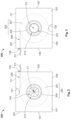
Figure 2 shows a first lateral view of a packaging system 200 according to a first embodiment of the invention. The packaging system 200 comprises a packaging box 201 obtained from the unassembled packaging box 100 described in relation to Figure 1. The packaging box 201 is the packaging box 100 when assembled and thus includes all features of the unassembled packaging box 100. In the assembled packaging box 201, the first face 101 is opposite the second face 103, such that the first mechanically weakened portion 145 is arranged face-to-face with the second mechanically weakened portion 157. Further, the first lateral section 105 is opposite the second lateral section 107, and the third lateral section 109 is opposite the fourth lateral section 111. The lateral view of Figure 2 shows the first face 101 of the packaging box 201.
-
The packaging system 200 further comprises an adhesive label tape reel 203, called label reel henceforth, that is housed in the packaging box 201, specifically between the first face 101 and the second face 103. The label reel 203 housed inside the box 201 is hidden but represented in Figure 2 in dashed lines for illustrative purposes. The label reel 203 comprises a tubular spool 205, and a continuous strip of adhesive label tape 207 wound or rolled-up around the spool 205. The outermost strip part 209 of the strip of the label tape 207 is drawn from the inside of the box 201 through the slit 139, such that a free extremity 211 of the outermost strip part 209 is on the outside of the box 201. In the assembled packaging box 201, the slit 139 extends orthogonally with respect to the first face 101 and with respect to the second face 103.
-
As shown on Figure 2, the first mechanically weakened portion 145 is axially aligned with the spool 205. In particular, the centre C1 of the first mechanically weakened portion 145 is centred within the interior 213 of the tubular spool 205. Preferably, the centre C1 is centred on a central axis of the tubular spool 205.
-
Figure 3 shows a second lateral view of the packaging system 200, in particular a lateral view opposed to the first lateral view of Figure 2. That is, Figure 3 shows the packaging system 200 from the side of the second face 103. Similarly to Figure 2, the label reel 203 is represented by dashed lines, with the exception of the extremity 211 of the outermost strip part 209 drawn outside the box 201 through the slit 139. Thus, the free extremity 211 of the strip of label tape 207 can be manually grasped, for example to be affixed to a processing unit of a processing apparatus. To facilitate the mounting and dismounting of the packaging system 200 in an apparatus, the free extremity 211 of the outermost strip part 209 can be kept outside, for example attached by form fit or through adhesive devices, during transporting and storing of the packaging system 200.
-
Figure 3 shows also that the second mechanically weakened portion 153 is axially aligned with the spool 205, and in particular that the centre C2 of the second mechanically weakened portion 157 is centred within the interior 213 of the tubular spool 205. Preferably, the centre C2 is centred on a central axis of the tubular spool 205. Thus, the first mechanically weakened portion 145 is arranged face-to-face with the second mechanically weakened portion 157, with the interior 213 of the spool 205 arranged therebetween.
-
The packaging system 200 allows for the reel 203 of sheet material 207 to be mounted in an apparatus for processing of the sheet material 207 while still inside the packaging box 201. The reel 203 does not need to be unboxed from its packaging box 201 before being mounted in an apparatus, because a support for the reel 203, for example the mandrel 409 described in the following, can be passed directly through the packaging box 201. By virtue of the weakening of the weakened portions 145, 157 being face-to-face, the support or mandrel 409 can be passed directly through the first weakened portion 145, the spool 203 and the second mechanically weakened portion 157.
-
In this embodiment, the first mechanically weakened portion 145 can be bent inwards or outwards with respect to be box when an object is inserted therein, in particular on the centre C1. Specifically, the first mechanically weakened portion 145 can be bent inwards, further facilitated by the creasing at its outline 147. Advantageously, the wedges W provide stability from the frictional adherence between the wedges W and the support inserted in the first weakened portion 145.
-
Similarly, the second mechanically weakened portion 157 can be easily separated from the second face 103 by pushing on said second mechanically weakened portion 157, thus rupturing the unperforated attaching parts 161, 163, 165 and 167. For example, when a support is passed through the first mechanically weakened portion 145 and the spool 205, the second mechanically weakened portion 157 can be pushed from the inside of the box 201 such that it is separated from the second face 103 and falls out of the box 201.
-
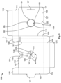
An apparatus for processing sheet material according to a second embodiment of the invention will now be described with reference to Figure 4. Here, the apparatus is a thermal transfer printer for printing on rolled-up sheet material, in particular on adhesive label tape provided in a reel configuration such as, for example, the reel 203.
-
Figure 4 shows a printer 400 having a base 401, a frame 403, and a hinged cover 405. Base 401, frame 403 and cover 405 represent a housing for the printer 400. For visibility purposes, in Figure 4, the cover 405 is in an opened position with respect to the cover hinge 407. A mandrel 409 protrudes orthogonally from the frame 403, and parallelly to the base 401.
-
The printer 400 comprises the packaging system 200 described in relation to Figures 2 and 3. Specifically, the packaging system 200 is mounted on the mandrel 409 such that the mandrel 409 is received through the first mechanically weakened portion 145, through the spool 205, and through the second mechanically weakened portion 147. Thus, the mandrel 409 is a bearing for the packaging system 200 and supports the reel 203. As shown on Figure 4, the mandrel 409 is passed through the packaging system 200 such that a free extremity 411 of the mandrel 409 is located on the other side of the frame 403 with respect to the packaging system 200.
-
In this embodiment, to further stabilise the installation of the packaging system 200 on the mandrel 409, a removable clamping device 411 is also slid on and clamped to the mandrel 409. The clamping device 413 fastens the packaging system 200 against the frame 403.
-
As shown on Figure 4, the outermost strip part 209 of the reel 203 is drawn out of the box 201 by the free extremity 211 towards a printing unit 415 housed in the housing 401, 403, 405. The free extremity is affixed in the printer unit 415 to be printed The printing unit 415 comprises a printer head 417 configured to selectively transfer ink or carbon from an unused thermal transfer ribbon 419 by heat and/or pressure action onto the label strip 207 received from the packaging system 200. Here, the unused thermal transfer ribbon 419 is fed in by a feed-in roll 421 and used thermal transfer ribbon 423 is fed-out by a feed-out roll 425. A printer output 427 outputs printed label tape. Further configuration details of the printing unit 415 may vary from printer to printer and its detailed description shall therefore be omitted here for conciseness.
-
The operation of the apparatus is enhanced through the packaging system 200, because the reel 203 does not need to be unboxed before being mounted on the mandrel 409. Instead, the reel 203 is mounted in the mandrel 409 while remaining inside the box. Thus mounting of the reel 203 is thus faster, and addition, the reel is protected from contamination while printing on the label strip 207. When the reel 203 needs to be exchanged, the entire packaging system 200 is moved away and stored, without risking an entangling of the strips of the label tape or an unwinding of the label tape 207 from its spool 205.
-
A method for mounting a reel of rolled-up sheet material in an apparatus for processing sheet material according to a third embodiment of the invention will now be described with reference to Figure 5. The method of the third embodiment is a method for mounting the reel 201 housed in the packaging box 200 in the printer 400.
-
The method starts with a step A (not represented on Figure 5) of providing the packaging system 200, comprising the assembled packaging box 201 and the label reel 203. As described above, the first mechanically weakened portion 145, the spool 205 and the second mechanically weakened portion 157 are aligned.
-
In a next step B, the packaging system 200 is plugged on the free extremity 411 of the mandrel 409 that is attached to the frame 403, with the first face 101 facing the towards frame 403 and the second face 103 facing away from the frame 403. Thus, the mandrel 409 penetrates the first mechanically weakened portion 145. In particular, the mechanical action of the mandrel 409 bends the first mechanically weakened portion 145 inwards, opening the first mechanically weakened portion 145 along the perforation lines, such that the wedges W are separated from each other and frictionally engage with the mandrel 409 inside the box 201. Advantageously, the mandrel 409 is automatically centred towards the centre C1 by the arrangement of the wedges W.
-
Then, in a step C, the mandrel 409 is passed further through the spool 205 of the reel 203 until abutting against the second mechanically weakened portion 157, held in place with the second face 103 by the attaching parts 161, 163, 165, 167.
-
In a step D, the packaging system 200 is pushed further on the mandrel 409 such that the free extremity 411 of the mandrel 409 penetrates the second mechanically weakened portion 157. Specifically, the mechanical action of the free extremity 411 of the mandrel 409 ruptures the attaching parts 161, 163, 165, 167, separating the second mechanically weakened portion 157 from the second face 103 such that it falls out of the box 201.
-
Thus, the packaging system 200 is mounted in the apparatus, here the printer 400, without needing to unbox the reel 203. This allows for the rolled-up sheet material 207 to be processed, that is, printed on, by the printer 400 without risking contamination of the reel, unwinding of the sheet material from its spool, or an entangling of sheet material strips when mounting, storing or transporting the reel.
Reference signs
-
- 100 unassembled packaging box
- 101 first face
- 103 second face
- 105 first lateral section
- 107 second lateral section
- 109 third lateral section
- 111 fourth lateral section
- 113 first connecting portion
- 115 second connecting portion
- 117 third connecting portion
- 119 fourth connecting portion
- 121 first sealing portion
- 123 second sealing portion
- 125 latching tongue
- 127 latching receptacle
- 129 latching portion
- 131 first hemi-circular excavation
- 133 first lateral edge
- 135 second hemi-circular excavation
- 137 second lateral edge
- 139 slit
- 141 first connecting boundary
- 143 second connecting boundary
- 145 first mechanically weakened portion
- 147 outline of the first mechanically weakened portion
- 149 first of the first two perforation lines
- 151 second of the first two perforation lines
- 153 first of the further two perforation lines
- 155 second of the further two perforation lines
- 157 second mechanically weakened portion
- 159 outline of the second mechanically weakened portion
- 161 first attaching part
- 163 second attaching part
- 165 third attaching part
- 167 fourth attaching part
- 200 packaging system
- 201 assembled packaging box
- 203 reel of the rolled-up sheet material
- 205 spool
- 207 rolled-up sheet material
- 209 outermost strip part of the rolled-up sheet material
- 211 free extremity of the rolled-up sheet material
- 213 interior of the spool
- 400 printer
- 401 base
- 403 frame
- 405 cover
- 407 covered hinge
- 409 mandrel
- 411 free extremity of the mandrel
- 413 clamping device
- 415 printing unit
- 417 printer head
- 419 unused thermal transfer ribbon
- 421 ribbon feed-in
- 423 used thermal transfer ribbon
- 425 ribbon feed-out
- 427 printer output
- A central axis of the first lateral section
- C1 centre of the first face
- C2 centre of the second face
- W wedge